Embed Size (px)
Citation preview
Installation, operation and maintenance manual ver. 2-3
w w w . d a s p o s . c o m I m p r o v i n g s a f e t y a t s e a
P a g e 1
LAS-10 AIO
Leakage Alarm System Atmospheric oil spray- and gas detection
All In One detector
Installation, operation and
maintenance manual
Installation, operation and maintenance manual ver. 2-3
w w w . d a s p o s . c o m I m p r o v i n g s a f e t y a t s e a
P a g e 2
Content
1. INTRODUCTION _________________________________________________________________________________ 3
2. SAFETY INSTRUCTIONS ___________________________________________________________________________ 4
2.1 OIL LEAKAGES _________________________________________________________________________________ 4
3. DESCRIPTION ___________________________________________________________________________________ 5
3.1 DETECTOR ___________________________________________________________________________________ 5
3.2 PSU/RELAY UNIT _______________________________________________________________________________ 5
4. TECHNICAL SPECIFICATIONS ______________________________________________________________________ 6
5. INSTALLATION AND COMMISSIONING ______________________________________________________________ 6
5.1 PREPARATIONS ________________________________________________________________________________ 6
5.2 INSTALLATION _________________________________________________________________________________ 7
5.2.1 PSU/Relay unit __________________________________________________________________________ 7
5.2.2 Detectors _______________________________________________________________________________ 7
5.2.3 Detector Print Card details _________________________________________________________________ 7
5.2.4 Power Supply Unit connections _____________________________________________________________ 9
5.3 COMMISSIONING ______________________________________________________________________________ 10
5.3.1 Test procedure _________________________________________________________________________ 10
6. OPERATION ___________________________________________________________________________________ 10
6.1 STATUS OF DETECTOR ___________________________________________________________________________ 10
6.1.1 LED Messages __________________________________________________________________________ 11
6.2 OIL DETECTION _______________________________________________________________________________ 12
6.3 GAS DETECTION _______________________________________________________________________________ 12
7. MAINTENANCE ________________________________________________________________________________ 13
7.1 FILTER _____________________________________________________________________________________ 13
7.2 SINTER FILTER ________________________________________________________________________________ 13
7.3 CALIBRATION ________________________________________________________________________________ 13
8. ILLUSTRATIONS ________________________________________________________________________________ 14
POWER SUPPLY __________________________________________________________________________________ 14
9. SPARE PARTS __________________________________________________________________________________ 15
9.1 LIST OF SPARE PARTS____________________________________________________________________________ 15
10. CONTACT INFORMATION ______________________________________________________________________ 16
10.1 QR-CODE ___________________________________________________________________________________ 16
Installation, operation and maintenance manual ver. 2-3
w w w . d a s p o s . c o m I m p r o v i n g s a f e t y a t s e a
P a g e 3
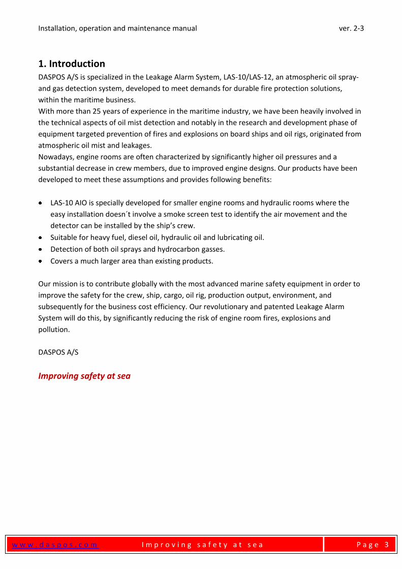
1. Introduction DASPOS A/S is specialized in the Leakage Alarm System, LAS-10/LAS-12, an atmospheric oil spray-
and gas detection system, developed to meet demands for durable fire protection solutions,
within the maritime business.
With more than 25 years of experience in the maritime industry, we have been heavily involved in
the technical aspects of oil mist detection and notably in the research and development phase of
equipment targeted prevention of fires and explosions on board ships and oil rigs, originated from
atmospheric oil mist and leakages.
Nowadays, engine rooms are often characterized by significantly higher oil pressures and a
substantial decrease in crew members, due to improved engine designs. Our products have been
developed to meet these assumptions and provides following benefits:
LAS-10 AIO is specially developed for smaller engine rooms and hydraulic rooms where the
easy installation doesn´t involve a smoke screen test to identify the air movement and the
detector can be installed by the ship’s crew.
Suitable for heavy fuel, diesel oil, hydraulic oil and lubricating oil.
Detection of both oil sprays and hydrocarbon gasses.
Covers a much larger area than existing products.
Our mission is to contribute globally with the most advanced marine safety equipment in order to
improve the safety for the crew, ship, cargo, oil rig, production output, environment, and
subsequently for the business cost efficiency. Our revolutionary and patented Leakage Alarm
System will do this, by significantly reducing the risk of engine room fires, explosions and
pollution.
DASPOS A/S
Improving safety at sea
Installation, operation and maintenance manual ver. 2-3
w w w . d a s p o s . c o m I m p r o v i n g s a f e t y a t s e a
P a g e 4
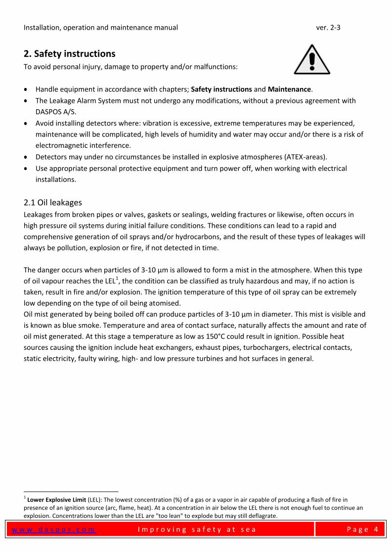
2. Safety instructions To avoid personal injury, damage to property and/or malfunctions:
Handle equipment in accordance with chapters; Safety instructions and Maintenance.
The Leakage Alarm System must not undergo any modifications, without a previous agreement with
DASPOS A/S.
Avoid installing detectors where: vibration is excessive, extreme temperatures may be experienced,
maintenance will be complicated, high levels of humidity and water may occur and/or there is a risk of
electromagnetic interference.
Detectors may under no circumstances be installed in explosive atmospheres (ATEX-areas).
Use appropriate personal protective equipment and turn power off, when working with electrical
installations.
2.1 Oil leakages
Leakages from broken pipes or valves, gaskets or sealings, welding fractures or likewise, often occurs in
high pressure oil systems during initial failure conditions. These conditions can lead to a rapid and
comprehensive generation of oil sprays and/or hydrocarbons, and the result of these types of leakages will
always be pollution, explosion or fire, if not detected in time.
The danger occurs when particles of 3-10 µm is allowed to form a mist in the atmosphere. When this type
of oil vapour reaches the LEL1, the condition can be classified as truly hazardous and may, if no action is
taken, result in fire and/or explosion. The ignition temperature of this type of oil spray can be extremely
low depending on the type of oil being atomised.
Oil mist generated by being boiled off can produce particles of 3-10 µm in diameter. This mist is visible and
is known as blue smoke. Temperature and area of contact surface, naturally affects the amount and rate of
oil mist generated. At this stage a temperature as low as 150°C could result in ignition. Possible heat
sources causing the ignition include heat exchangers, exhaust pipes, turbochargers, electrical contacts,
static electricity, faulty wiring, high- and low pressure turbines and hot surfaces in general.
1 Lower Explosive Limit (LEL): The lowest concentration (%) of a gas or a vapor in air capable of producing a flash of fire in
presence of an ignition source (arc, flame, heat). At a concentration in air below the LEL there is not enough fuel to continue an explosion. Concentrations lower than the LEL are "too lean" to explode but may still deflagrate.
Installation, operation and maintenance manual ver. 2-3
w w w . d a s p o s . c o m I m p r o v i n g s a f e t y a t s e a
P a g e 5
3. Description2
The LAS-10 AIO comprises two main components:
Detector
PSU/Relay unit
3.1 Detector
The detector consists of an aluminium housing containing a sealed enclosure for the detector PCB. Air
inlets in the housing allows air to be drawn inside the detector by the built-in fan, pass the sinter
filter(containing a gas sensor) and through the replaceable filter, creating a differential pressure,
monitored by a pressure sensor. The fan is shielded by the protective grille and the detector is connected
to the PSU Relay unit through the detector plug and cable. Both the gas sensor and the pressure sensor
are located on the detector PCB.
3.2 PSU/Relay unit
The PSU Relay unit consists of aluminium housing, fitted with cable glands, containing the PSU and the
interface PCB on which you will find the Fault output relay and the Alarm output relay.
The presence of oil- or gas polluted air in the surrounding atmosphere of the detector will either increase
the aforementioned differential pressure or the output of the gas sensor, and if these readings exceeds
predetermined values in the alarm settings, the system will activate the alarm relay.
As default the Hydro Carbon gas sensor are factory set to activate the alarm relay at 17% of the LEL for
Methane – and lower for other Hydro Carbon gasses.
The system also has some built-in fault monitoring, which will activate the fault relay. See “8. Fault
finding”, for a specification.
2 Components in Bold letters are available as spareparts, see list of spareparts.
Installation, operation and maintenance manual ver. 2-3
w w w . d a s p o s . c o m I m p r o v i n g s a f e t y a t s e a
P a g e 6
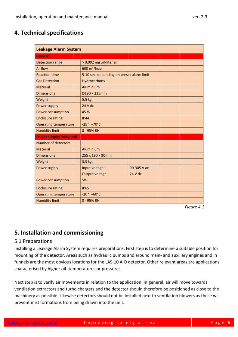
4. Technical specifications
Leakage Alarm System
Detector
Detection range > 0,002 mg oil/liter air
Airflow 600 m³/hour
Reaction time 5-10 sec. depending on preset alarm limit
Gas Detection Hydrocarbons
Material Aluminium
Dimensions Ø190 x 235mm
Weight 5,5 kg
Power supply 24 V dc
Power consumption 45 W
Enclosure rating IP44
Operating temperature -25 ~ +70°C
Humidity limit 0 - 95% RH
Power supply/Relay unit
Number of detectors 1
Material Aluminium
Dimensions 255 x 190 x 90mm
Weight 3,3 kgs
Power supply Input voltage: 90-305 V ac
Output voltage: 24 V dc
Power consumption 5W
Enclosure rating IP65
Operating temperature -20 ~ +60°C
Humidity limit 0 - 95% RH
Figure 4.1
5. Installation and commissioning
5.1 Preparations
Installing a Leakage Alarm System requires preparations. First step is to determine a suitable position for
mounting of the detector. Areas such as hydraulic pumps and around main- and auxiliary engines and in
funnels are the most obvious locations for the LAS-10 AIO detector. Other relevant areas are applications
characterised by higher oil- temperatures or pressures.
Next step is to verify air movements in relation to the application. In general, air will move towards
ventilation extractors and turbo chargers and the detector should therefore be positioned as close to the
machinery as possible. Likewise detectors should not be installed next to ventilation blowers as these will
prevent mist formations from being drawn into the unit.
Installation, operation and maintenance manual ver. 2-3
w w w . d a s p o s . c o m I m p r o v i n g s a f e t y a t s e a
P a g e 7
5.2 Installation
5.2.1 PSU/Relay unit
The PSU/Relay unit is mounted next to the detector in the engine room.
Avoid installing the PSU/Relay unit where: vibration is excessive, extreme temperatures may be
experienced, maintenance will be difficult, high levels of humidity and water may occur and there is a risk
of electromagnetic interference.
5.2.2 Detectors
The detector is designed to be mounted in the engine room and should be located as close to the relevant
application as possible. In the interest of accessibility, during e.g. maintenance, mount the detector in or
next to high traffic areas and in reasonable heights if possible.
Avoid installing the detector where: vibration is excessive, extreme temperatures may be experienced,
maintenance will be difficult, high levels of humidity and water may occur and there is a risk of
electromagnetic interference.
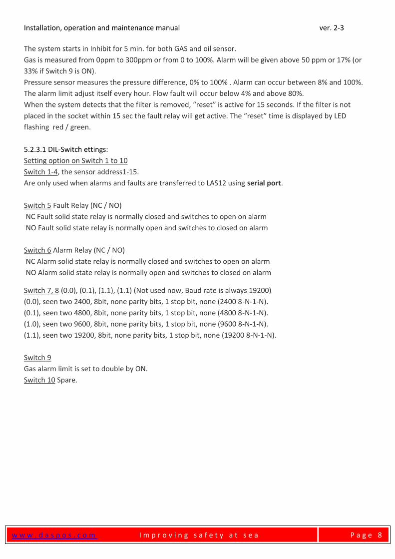
5.2.3 Detector Print Card details
The unit can operate as stand-alone or be part of a larger system using RS485/422 serial port, and alarm
and fault relay outputs.
The system consists of the following parts
A sensor with print and fan, which is built into a specially designed aluminum housing.
D = 188mm H = 235mm and
A connection box in gray aluminum. 90x160x260mm excl. adapters and cables.
The box is IP65.
Sensor print card LAS-10 AIO has connection for:
Fan Motor, 4 terminals (+ DCV, 0V, NC, NC).
Supply and relay outputs, 8 terminals (+ DCV, DCV +, 0V, 0V, Alarm1-2, FAULT1-2).
RS485/422 serial port, five terminals (A, B, Y, Z, 0V).
LED connector, Red / Green LED for alarm and fault indication.
Hoses for pressure sensor, (LOW and HIGH).
Programming connector PIC Pro +5 V..
System description:
Measurement of gases and vaporized oil in the air: 1000 times per second. The measured differential
pressure across a filter using the built-in fan.
Ambient temperature, max 60 C °.
Supply 90 to 305 Vac.
Internal power supply, 22Vdc to 27Vdc.
Alarm and error Solid State relay outputs max 24VDC/100mA.
CPU program (PIC18F2620) sits in base for easy replacement and software update.
Installation, operation and maintenance manual ver. 2-3
w w w . d a s p o s . c o m I m p r o v i n g s a f e t y a t s e a
P a g e 8
The system starts in Inhibit for 5 min. for both GAS and oil sensor.
Gas is measured from 0ppm to 300ppm or from 0 to 100%. Alarm will be given above 50 ppm or 17% (or
33% if Switch 9 is ON).
Pressure sensor measures the pressure difference, 0% to 100% . Alarm can occur between 8% and 100%.
The alarm limit adjust itself every hour. Flow fault will occur below 4% and above 80%.
When the system detects that the filter is removed, “reset” is active for 15 seconds. If the filter is not
placed in the socket within 15 sec the fault relay will get active. The “reset” time is displayed by LED
flashing red / green.
5.2.3.1 DIL-Switch ettings:
Setting option on Switch 1 to 10
Switch 1-4, the sensor address1-15.
Are only used when alarms and faults are transferred to LAS12 using serial port.
Switch 5 Fault Relay (NC / NO)
NC Fault solid state relay is normally closed and switches to open on alarm
NO Fault solid state relay is normally open and switches to closed on alarm
Switch 6 Alarm Relay (NC / NO)
NC Alarm solid state relay is normally closed and switches to open on alarm
NO Alarm solid state relay is normally open and switches to closed on alarm
Switch 7, 8 (0.0), (0.1), (1.1), (1.1) (Not used now, Baud rate is always 19200)
(0.0), seen two 2400, 8bit, none parity bits, 1 stop bit, none (2400 8-N-1-N).
(0.1), seen two 4800, 8bit, none parity bits, 1 stop bit, none (4800 8-N-1-N).
(1.0), seen two 9600, 8bit, none parity bits, 1 stop bit, none (9600 8-N-1-N).
(1.1), seen two 19200, 8bit, none parity bits, 1 stop bit, none (19200 8-N-1-N).
Switch 9
Gas alarm limit is set to double by ON.
Switch 10 Spare.
Installation, operation and maintenance manual ver. 2-3
w w w . d a s p o s . c o m I m p r o v i n g s a f e t y a t s e a
P a g e 9
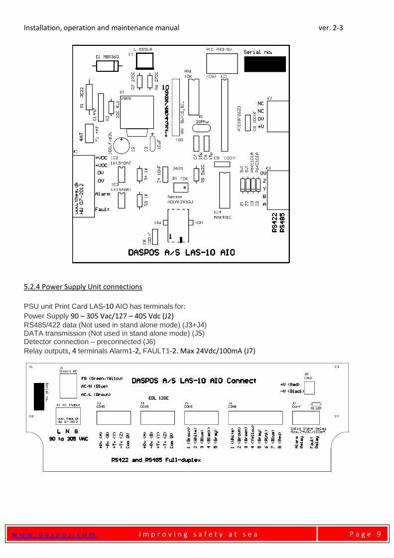
5.2.4 Power Supply Unit connections
PSU unit Print Card LAS-10 AIO has terminals for: Power Supply 90 – 305 Vac/127 – 405 Vdc (J2) RS485/422 data (Not used in stand alone mode) (J3+J4) DATA transmission (Not used in stand alone mode) (J5) Detector connection – preconnected (J6)
Relay outputs, 4 terminals Alarm1-2, FAULT1-2. Max 24Vdc/100mA (J7)
Installation, operation and maintenance manual ver. 2-3
w w w . d a s p o s . c o m I m p r o v i n g s a f e t y a t s e a
P a g e 1 0
5.3 Commissioning
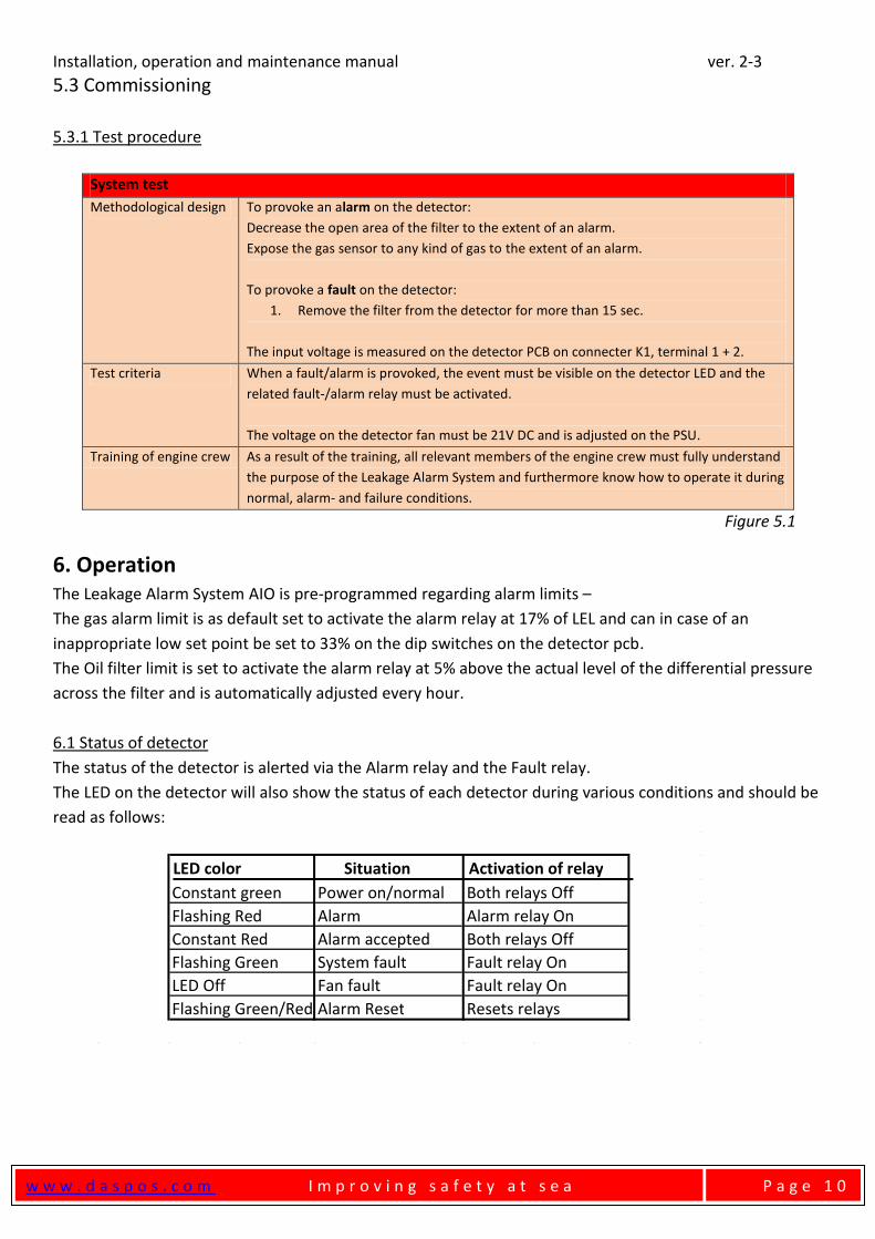
5.3.1 Test procedure
System test
Methodological design To provoke an alarm on the detector:
1. Decrease the open area of the filter to the extent of an alarm.
2. Expose the gas sensor to any kind of gas to the extent of an alarm.
3.
4. To provoke a fault on the detector:
5. 1. Remove the filter from the detector for more than 15 sec.
The input voltage is measured on the detector PCB on connecter K1, terminal 1 + 2.
Test criteria When a fault/alarm is provoked, the event must be visible on the detector LED and the
related fault-/alarm relay must be activated.
The voltage on the detector fan must be 21V DC and is adjusted on the PSU.
Training of engine crew As a result of the training, all relevant members of the engine crew must fully understand
the purpose of the Leakage Alarm System and furthermore know how to operate it during
normal, alarm- and failure conditions.
Figure 5.1
6. Operation The Leakage Alarm System AIO is pre-programmed regarding alarm limits –
The gas alarm limit is as default set to activate the alarm relay at 17% of LEL and can in case of an
inappropriate low set point be set to 33% on the dip switches on the detector pcb.
The Oil filter limit is set to activate the alarm relay at 5% above the actual level of the differential pressure
across the filter and is automatically adjusted every hour.
6.1 Status of detector
The status of the detector is alerted via the Alarm relay and the Fault relay.
The LED on the detector will also show the status of each detector during various conditions and should be
read as follows:
Situation
Constant green Power on/normal Both relays Off
Flashing Red Alarm Alarm relay On
Constant Red Alarm accepted Both relays Off
Flashing Green System fault Fault relay On
LED Off Fan fault Fault relay On
Flashing Green/Red Alarm Reset Resets relays
LED color Activation of relay
Installation, operation and maintenance manual ver. 2-3
w w w . d a s p o s . c o m I m p r o v i n g s a f e t y a t s e a
P a g e 1 1
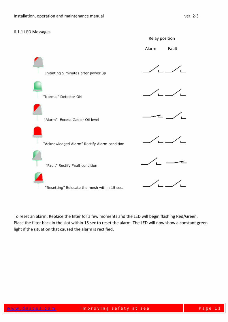
6.1.1 LED Messages
Relay position
Alarm Fault
Initiating 5 minutes after power up
“Normal” Detector ON
“Alarm” Excess Gas or Oil level
“Acknowledged Alarm” Rectify Alarm condition
“Fault” Rectify Fault condition
“Resetting” Relocate the mesh within 15 sec.
To reset an alarm: Replace the filter for a few moments and the LED will begin flashing Red/Green.
Place the filter back in the slot within 15 sec to reset the alarm. The LED will now show a constant green
light if the situation that caused the alarm is rectified.
Installation, operation and maintenance manual ver. 2-3
w w w . d a s p o s . c o m I m p r o v i n g s a f e t y a t s e a
P a g e 1 2
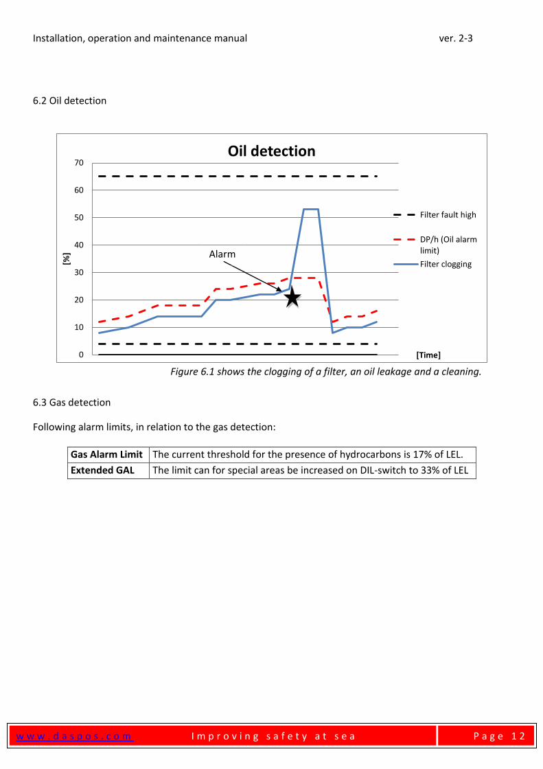
6.2 Oil detection
Figure 6.1 shows the clogging of a filter, an oil leakage and a cleaning.
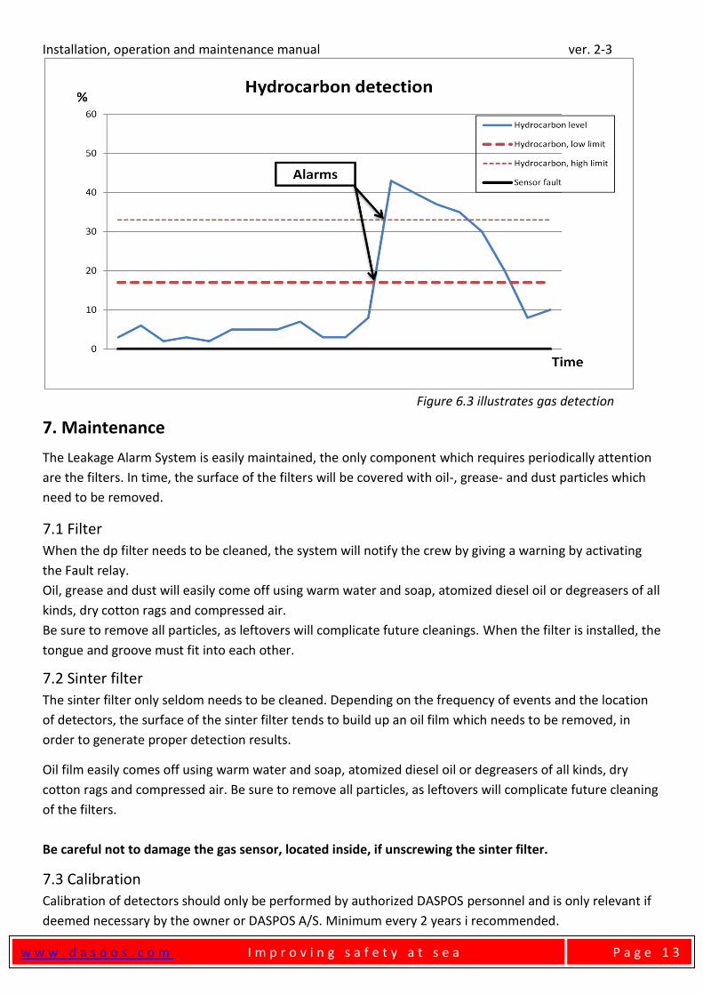
6.3 Gas detection
Following alarm limits, in relation to the gas detection:
Gas Alarm Limit The current threshold for the presence of hydrocarbons is 17% of LEL.
Extended GAL The limit can for special areas be increased on DIL-switch to 33% of LEL
0
10
20
30
40
50
60
70
[%]
[Time]
Oil detection
Filter fault high
DP/h (Oil alarm limit)
Filter clogging Alarm
Installation, operation and maintenance manual ver. 2-3
w w w . d a s p o s . c o m I m p r o v i n g s a f e t y a t s e a
P a g e 1 3
Figure 6.3 illustrates gas detection
7. Maintenance
The Leakage Alarm System is easily maintained, the only component which requires periodically attention
are the filters. In time, the surface of the filters will be covered with oil-, grease- and dust particles which
need to be removed.
7.1 Filter
When the dp filter needs to be cleaned, the system will notify the crew by giving a warning by activating
the Fault relay.
Oil, grease and dust will easily come off using warm water and soap, atomized diesel oil or degreasers of all
kinds, dry cotton rags and compressed air.
Be sure to remove all particles, as leftovers will complicate future cleanings. When the filter is installed, the
tongue and groove must fit into each other.
7.2 Sinter filter
The sinter filter only seldom needs to be cleaned. Depending on the frequency of events and the location
of detectors, the surface of the sinter filter tends to build up an oil film which needs to be removed, in
order to generate proper detection results.
Oil film easily comes off using warm water and soap, atomized diesel oil or degreasers of all kinds, dry
cotton rags and compressed air. Be sure to remove all particles, as leftovers will complicate future cleaning
of the filters.
Be careful not to damage the gas sensor, located inside, if unscrewing the sinter filter.
7.3 Calibration
Calibration of detectors should only be performed by authorized DASPOS personnel and is only relevant if
deemed necessary by the owner or DASPOS A/S. Minimum every 2 years i recommended.
Installation, operation and maintenance manual ver. 2-3
w w w . d a s p o s . c o m I m p r o v i n g s a f e t y a t s e a
P a g e 1 4
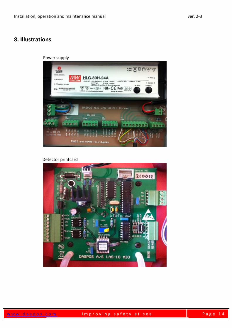
8. Illustrations
Power supply
Detector printcard
Installation, operation and maintenance manual ver. 2-3
w w w . d a s p o s . c o m I m p r o v i n g s a f e t y a t s e a
P a g e 1 5
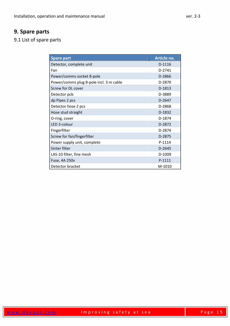
9. Spare parts
9.1 List of spare parts
Spare part Article no.
Detector, complete unit D-1116
Fan D-2741
Power/comms socket 8-pole D-2866
Power/comms plug 8-pole incl. 3 m cable D-2870
Screw for DL cover D-1813
Detector pcb D-3889
dp Pipes 2 pcs D-2647
Detector hose 2 pcs D-2868
Hose stud straight D-1832
O-ring, cover D-1874
LED 3-colour D-2872
Fingerfilter D-2874
Screw for fan/fingerfilter D-2875
Power supply unit, complete P-1114
Sinter filter D-2645
LAS-10 filter, fine mesh D-1009
Fuse, 4A 250v P-1111
Detector bracket M-1010

Installation, operation and maintenance manual ver. 2-3
w w w . d a s p o s . c o m I m p r o v i n g s a f e t y a t s e a
P a g e 1 6
10. Contact Information
Address: DASPOS A/S
Vesterlundvej 9
DK-2730 Herlev
Ph.: +45 4432 7767 (+45 HI DASPOS)
Fax: +45 4485 2475
Website: www.daspos.com
Email, service: [email protected]
Email, other inquiries: [email protected]
10.1 QR-code Scan and go to our website!