Embed Size (px)
Citation preview

HAL Id: hal-02894371https://hal.archives-ouvertes.fr/hal-02894371
Submitted on 8 Jul 2020
HAL is a multi-disciplinary open accessarchive for the deposit and dissemination of sci-entific research documents, whether they are pub-lished or not. The documents may come fromteaching and research institutions in France orabroad, or from public or private research centers.
L’archive ouverte pluridisciplinaire HAL, estdestinée au dépôt et à la diffusion de documentsscientifiques de niveau recherche, publiés ou non,émanant des établissements d’enseignement et derecherche français ou étrangers, des laboratoirespublics ou privés.
Effects of swirl on the stabilization of non-premixedoxygen-enriched flames above coaxial injectors
Arthur Degenève, Clément Mirat, Jean Caudal, Ronan Vicquelin, ThierrySchuller
To cite this version:Arthur Degenève, Clément Mirat, Jean Caudal, Ronan Vicquelin, Thierry Schuller. Effects of swirlon the stabilization of non-premixed oxygen-enriched flames above coaxial injectors. Journal of En-gineering for Gas Turbines and Power, American Society of Mechanical Engineers, 2019, 141 (12),pp.121018. �10.1115/1.4045024�. �hal-02894371�
OATAO is an open access repository that collects the work of Toulouseresearchers and makes it freely available over the web where possible
Any correspondence concerning this service should be sent
to the repository administrator: [email protected]
This is an author’s version published in: http://oatao.univ-toulouse.fr/25706
To cite this version:
Degenève, Arthur and Mirat, Clément and Caudal, Jean and Vicquelin, Ronan and Schuller, Thierry Effects of swirl on the stabilization of non-premixed oxygen-enriched flames above coaxial injectors. (2019) Journal Of Engineering For Gas Turbines And Power, 141 (12). 121018. ISSN 0742-4795 .
Official URL:
https://doi.org/10.1115/1.4045024
Open Archive Toulouse Archive Ouverte


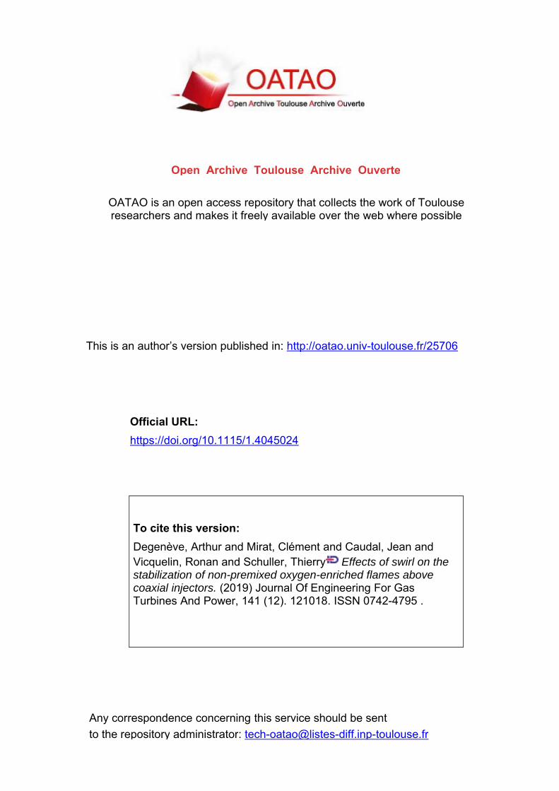
remain in the jet like regime [26]. Second, when both the momentum flux ratio J and the annular swirl number S2 are high enough,the flow field is strongly modified with the appearance of a stableCRZ that pushes the reaction zone upstream and makes the flamemore compact.
All the investigated flames in this first set of experiments arewell attached to the lips of the central tube. This feature is exemplified in Fig. 4 showing the OH* emission distribution of nineselected flames. These observations remain valid for all the 91operating conditions investigated when S1 ¼ 0; 0:75 � J � 8 and0 � S2 � 1:1. Flame images of the OH* emission intensity collected with a short exposure time Dt ¼ 1 ls, not shown here,always detect OH* light close to the injector lip.
The flame front starts at the edge of the internal injector rim,which is the most upstream point where the methane and the oxidizer meet. For flames obtained with a high outer swirl numberS2, the OH* peak emission slightly shifts radially above the oxidizer stream, as in the top row images in Fig. 4 when S2 ¼ 1. Inthese conditions, the CRZ lies just above the central injection tubeoutlet so that a small fraction of the methane stream is pushed
toward the annular channel upstream within the oxidizer flow.This yields a diffusion flame front anchored in the annular streama few millimeters below the injection plane. This reaction takingplace inside the annular channel is not visible from the view angleof Fig. 4 due to the surrounding metallic components of theburner, but is clearly visible in images taken from the top viewabove the injector (not shown here). Though this flame protrudinginside the injector is not entirely attached, it cannot be consideredlifted either. In all the experiments carried out in the absence ofinner swirl S1¼ 0, it was not possible to lift the oxy flames withYO2;2 ¼ 0:40. These flames remain attached to the injector nozzlelip. In this stabilization mode, the injector nozzle is submitted tohigh thermal stress.
4 Effect of S1 on Flame Stabilization
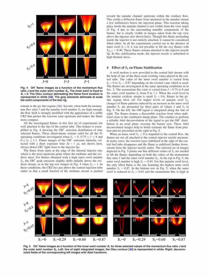
A swirl motion is now provided to the central fuel stream withthe help of one of the three axial swirling vanes placed in the central tube. The value of the inner swirl number is varied fromS1¼ 0 to S1 ¼ 0:87 depending on the twisted vane which is used.The flames are investigated at the same operating conditions as inSec. 2. The momentum flux ratio is varied from J¼ 0.75 to 8 andthe outer swirl number S2 from 0 to 1.1. When the swirl level inthe annular oxidizer stream is small S2 < 0:6, flames in the jetlike regime blow off. For higher levels of annular swirl S2,changes of flame patterns induced by an increase in the inner swirlnumber S1 are presented for three pairs of values J and S2 inFig. 5. On the left, the OH*signal is integrated along the line ofsight. The flames feature a discernible reaction front when stabilized close to the combustor dump plane. This enables to performa reliable Abel deconvolution of the signal to get the OH* distribution in an axial plane crossing the burner axis. These Abeldeconvoluted images help to better estimate the flame front position and are presented on the right in Fig. 5.
When an inner swirl S1 > 0 is imparted to the central flow, theflames are not all attached to the central injector nozzle anymore.In many cases, the reaction layer stabilized at the edge of the central fuel tube disappears and the flame is stabilized further downstream from the injector nozzle outlet. The selected set of imagesdepicted in Fig. 5 points out that different values of S1 are neededto lift the flames depending on both the values of the momentumflux ratio J and the outer swirl number S2. At the top in Fig. 5, theouter swirl number is high S2 ¼ 0:85. For this annular swirl level,the only lifted flame is the one featuring the highest inner swirlnumber S1 ¼ 0:87. In the bottom row in Fig. 5, when the outerswirl is reduced to S2 ¼ 0:65 and the momentum flux is high in
Fig. 4 OH* flame images as a function of the momentum fluxratio J and the outer swirl number S2. The inner swirl is fixed toS1 5 0. The Otsu contour delineating the flame front location isrepresented in white [34]. The gray elements delineate at scalethe solid components of the test rig.
Fig. 5 OH* flame images as a function of the inner swirl number S1 for three selected values of the momentum flux ratio J andthe outer swirl number S2. Left: line of sight integrated images; the Otsu contour [34] is represented in white. Right: deconvo-luted fields of the corresponding left images with Abel transform.


� Type C flame is a flame for which the Type A diffusion jetflame front has disappeared. The reaction layer is now onlylocated between the fuel stream and the CRZ where the recirculating hot gases and the oxidizer are mixed. Though theflame is stabilized close to the injector, the flame front is notin contact with any metallic component. The flame is therefore lifted and fully aerodynamically stabilized. In this mode,the liftoff height remains small Lf =d1 < 1.
� Type D flame has the same topology as Type C flame, but itis stabilized further downstream from the injector outlet withLf =d1 > 1. As reported in Fig. 5, the liftoff height in thismode is very sensitive to the injection conditions.
Transition from Type A to Type B flames is smooth. Whentype A flames with S1¼ 0 feature a CRZ, the reaction frontbetween methane and the CRZ is diffuse and hardy discernible(see Fig. 5). This is attributed to the momentum of the nonswirlinginner jet that pushes the reaction zone downstream. For Type Aflames featuring a CRZ, the flame front close to the CRZ is diffuse. Conversely, a type B flame features a bright V flame frontbetween the methane stream and the CRZ. The higher swirl levelin the inner jet favors vortex breakdown which places the CRZmore upstream. Transition from type B to type C flames is steeper.As soon as the diffusion reaction layer in the shear layer betweenthe two coaxial streams has disappeared, the lifted V flame produces more sound and cannot return back to the type B shapewithout large modifications of the operating conditions.
Flames are now analyzed with both deconvoluted images toidentify where the flame is stabilized and line of sight imageswhich are more representative of the size and volume occupied bythe flame. As shown in Figs. 5 and 6, the compactness of the flameis drastically impacted by the inner swirl number S1. One mustrecall that the Reynolds number in the annular stream is kept fixedand equal to Re2 ¼ 12,000 in these experiments. At the top row inFig. 5, the momentum flux ratio is J¼ 4, only the inner swirl number S1 differs between the four flames. For these injection conditions, the thermal power P¼ 9.4 kW and global equivalence ratioU ¼ 0:35 are fixed. An increase in the inner swirl number S1
sharply increases the flame compactness and decreases the flamelength. It can be further seen that the gain of compactness isdirectly correlated with the transition from Type B to Type Cregimes. This is also well illustrated in the middle row in Fig. 5for J¼ 8 and S2 ¼ 0:8.
A complete characterization of the stabilization mechanism ofthese flames requires more elaborated diagnostics. At this stage,one may already attempt the following conjecture. In Type A and
Type B regimes, a diffusion flame front is anchored to the centralnozzle rim. When swirl is high enough, a central recirculationbubble forms in this flow. This CRZ cannot, however, settle closeto the injector outlet due to burned gas acceleration produced inthe central flow by the diffusion reaction layer anchored on theburner rim. When this diffusion reaction layer disappears and theflame stabilizes in Type C regime, the CRZ is no longer pushedby the burned gases and can freely protrude further upstream.This in turn largely shortens the flame length. It is worth mentioning that the inner fuel tube only provides a small amount of thetotal mass flow rate and axial momentum flux. In these conditions,it has been shown that even small variations of the inner swirlnumber have a large impact on the flame and flow patterns.
5 Effect of Confinement and Thermal Environment
It is now worth considering how confinement due to the combustion chamber sidewalls affects the flame topology. A criterionbased on the confinement ratio Cr ¼ W2=ðpr2
2Þ, whereW¼ 150 mm is the width of the square combustion chamber andr2 ¼ 10 mm the outer radius of the annular stream, is used to discriminate whether aerodynamics effects caused by the confinement need to be considered [38,39]. It has been shown in a formerstudy conducted with premixed flames that the Oxytec combustion chamber operates in a free jet regime [33]. Besides, wall temperatures at the injector nozzle lip [40], along the combustionchamber back plate and in the outer recirculation zones [41,42],can also affect flame stabilization and the liftoff height by preheating the gases.
In order to verify whether the presence of the combustionchamber sidewalls is responsible for the previous observations,experiments are now carried out without any combustion chamber. The same injector is used, but the flames are stabilized in quiescent atmosphere above the same chamber back plane and at thesame flow operating conditions as in Sec. 3 for a central swirllevel S1 ¼ 0:87. In the absence of combustion chamber, the injection device does not heat up and remains at ambient temperatureT0 ¼ 293 K, except for the tip of the inner tube. This new configuration of the burner prevents (i) the reactants from preheating (ii)the formation of an outer recirculation zone filled with hot burnedgases and (iii) changes of the gas composition of the flowentrained by the annular oxidizer jet.
The results are shown in Fig. 9. Line of sight integrated OH*
intensity distributions are represented for nine flames featuringdifferent values of momentum flux ratio J and outer swirl numberS2. The gray elements delineate at scale the solid components of
Fig. 9 OH* flame images as a function of the momentum flux ratio J and the outer swirl number S2. S1 0:87. Left: flames sta-bilized without the combustion chamber sidewalls. Right: flames stabilized inside the Oxytec combustion chamber delineatedin gray.


7 Effect Oxygen Enrichment on Flame Topology
So far, only the aerodynamic characteristics of the flow insidethe combustion chamber were modified. It is finally worth exploring the effects of chemistry with the help of a Damk€ohler number.This number is varied by modifying the level of oxygen enrichment in the annular stream. The impact of the O2 enrichment onflame topology is analyzed with OH* deconvoluted images inFig. 12 and with a stabilization regime map in Fig. 13. As inSec. 6, experiments are reported for a fixed inner swirl numberS1¼ 0.87. The oxygen mass fraction YO2 ;2 ranges from 0.23, corresponding to an air mixture, to 0.5. For a fixed momentum fluxratio J, increasing YO2 ;2 leads to a reduction of the global equivalence ratio. It appears that the flames feature the same topologiesand the same type of stabilization modes as reported in Fig. 8.When the oxygen enrichment increases, the liftoff height reducesand the flames are more difficult to detach from the injector rim.As depicted in Fig. 13, transition from Type B to type C flamesdepends on YO2;2. When the O2 mass fraction is lower thanYO2;2 ¼ 0:30, all the reported flames are lifted. Conversely, whenit is increased to YO2 ;2 ¼ 0:50, only the flames with a moderateannular swirl S2 and a high momentum flux in the inner fuelstream are lifted. Between these two limits, the mass fractionYO2;2 ¼ 0:40 yields the best delineation between the lifted and theattached regimes. This oxygen enrichment allows to easily characterize the transition from Type B to type C regimes for a largerange of combinations of J and S2. This property has motivatedthe choice in this study to conduct the major part of the experiments at this level of O2 enrichment.
Further experiments, not reported here, were also conducted atdifferent levels of O2 enrichment, but without inner swirl S1¼ 0.These flames are all attached to the nozzle rim, except a fewflames with air as the oxidizer. All these experiments confirm thatadding a swirl motion S1 to the inner fuel stream confers a highflexible capacity to lift the flame, independently from the O2
enrichment in the annular flow.
8 Conclusion
The impact of swirl on the stabilization of non premixedoxygen enriched flames has been investigated above a coaxialinjector. In this system, methane is injected in the inner streamwhich is eventually put in rotation by an axial swirling vane. Anoxidizing O2/N2 mixture composed of 40% of oxygen in massflows into a swirling annular stream generated by an axial plustangential device. Flame topologies stabilized above this injectorhave been investigated with OH* chemiluminescence images.
It has been shown that flame attachment and flame liftoff heightmainly depend on the momentum flux ratio J ¼ q2u2
z;2=q1u2z;1.
When the momentum flux ratio J is small, the flame is lifted andthe liftoff height is maximum. Increasing J progressively reducesthe liftoff height until the flames anchor to the rim of the centralinjector. This dimensionless number, disregarded in many studiesin which the coflow velocity remains small, is here varied fromJ¼ 0.75 to 8 and used systematically to interpret the flame topologies observed above the injector.
It has been found that swirling the annular oxidizer stream orthe inner fuel stream yield opposite effects. Without inner swirlS1¼ 0, flames could not be lifted over the range of operating conditions covered in this study. A major finding of this work is thatwhen the central fuel stream is impregnated with swirl S1 > 0,lifted flames with a stable central recirculating zone could bereached over a wide set of operating conditions. In this case, flamestabilization and liftoff characteristics have been found to dependon the inner swirl level S1, the outer swirl level S2 and the momentum ratio J between the two streams. Increasing the tangentialouter momentum in the annular channel by increasing the outerswirl number S2 or decreasing the inner axial momentum flux inthe central tube by increasing the momentum flux ratio J lowersthe position of the recirculating bubble and favors flame attachment to the central injector rim. Conversely, increasing the tangential inner momentum by increasing the inner swirl level S1 orincreasing the inner axial momentum by lowering the momentumflux ratio J favors flame detachment from the central injector rim.
Changes of the flame topology have been classified in four successive categories depicting the apparition and the position of distinct reaction layers in the flow as the inner swirl level increases.These four topologies largely impact the thermal stress to theinjector and the flame compactness. Transitions from one topology to the following follow a similar pathway when S1, S2, and Jare modified. These topologies have also been found to be notaltered by the combustion chamber sidewalls. This proves thatflame stabilization above this injector is not impaired by the presence of outer recirculation zones or by the gas composition of theexternal entrained flow.
The impact of a diverging cup placed at the outlet of the oxidizer stream has also been characterized. Increasing the quarlangle of the annular nozzle has been shown to greatly alter theflame topology by decreasing the flame liftoff height and promoting flame attachment to the central injector nozzle. Increasing thequarl angle lowers the position of the stagnation point of the central recirculating bubble. This leads to reduced flame liftoffheights independently from the swirl levels in the central andannular streams and the momentum ratio between these streams.These experiments confirm that a quarl is an independent controlparameter to adjust flame liftoff.
Fig. 12 OH* flame images as a function of the mass fraction ofoxygen in the annular stream YO2 ;2 for two selected values ofthe momentum flux ratio J and the outer swirl number S2.Images are deconvoluted with the Abel transform. The innerswirl number is set to S1 0:87.
Fig. 13 Transition between Type B and Type C topology assketched in Fig. 7, mapped with respect to the momentum fluxratio J and the outer swirl number S2 for different level of oxy-gen enrichment YO2 ;2. The inner swirl number is set toS1 0:87.

Finally, the effects of mixture reactivity have been analyzed bychanging the level of oxygen in the oxidizer annular stream.When the O2 enrichment increases, lifted non premixed flamescan be stabilized downstream coaxial injectors by increasing S1 ordecreasing S2 or J. The main parameters allowing to control theliftoff height have therefore been identified. In particular, it hasbeen shown that the use of the inner swirl yields both compactand lifted flames. The lifted flame regime is interesting from anindustrial perspective to reduce the size of the equipment whilelimiting the thermal stress to the injector nozzle. These experiments were conducted with a coaxial injector in which the annularoxidizer velocity is not small compared to the central fuel jetvelocity that is typical of many industrial injectors.
Acknowledgment
This work is supported by the Air Liquide, CentraleSup�elec,and CNRS Chair on oxy combustion and heat transfer for energyand environment and by the OXYTEC project (ANR 12 CHIN0001) from l’Agence Nationale de la Recherche.
References[1] De Persis, S., Foucher, F., Pillier, L., Osorio, V., and G€okalp, I., 2013, “Effects
of O2 Enrichment and CO2 Dilution on Laminar Methane Flames,” Energy, 55,pp. 1055–1066.
[2] Baukal, C. E., and Gebhart, B., 1997, “Oxygen-Enhanced/Natural Gas FlameRadiation,” Int. J. Heat Mass Transfer, 40(11), pp. 2539–2547.
[3] Cieutat, D., Sanchez-Molinero, I., Tsiava, R., Recourt, P., Aimard, N., andPr�ebend�e, C., 2009, “The Oxy-Combustion Burner Development for the CO2
Pilot at Lacq,” Energy Procedia, 1(1), pp. 519–526.[4] Toftegaard, M. B., Brix, J., Jensen, P. A., Glarborg, P., and Jensen, A. D., 2010,
“Oxy-Fuel Combustion of Solid Fuels,” Prog. Energy Combust. Sci., 36(5), pp.581–625.
[5] Ivernel, A., and Vernotte, P., 1979, “Etude Exp�erimentale de L’am�eliorationDes Transferts Convectis Dans Les Fours Par Suroxyg�enation du Comburant,”Rev. Gener. Therm., 18(210–211), pp. 375–391.
[6] Samaniego, J., Labegorre, B., Egolfopoulos, F., Ditaranto, M., Sautet, J., andCharon, O., 1998, “Mechanism of Nitric Oxide Formation in Oxygen-NaturalGas Combustion,” Symp. (Int.) Combust., 27(1), pp. 1385–1392.
[7] Chen, R., and Axelbaum, R., 2005, “Scalar Dissipation Rate at Extinction andthe Effects of Oxygen-Enriched Combustion,” Combust. Flame, 142(1–2), pp.62–71.
[8] Boushaki, T., Sautet, J., Salentey, L., and Labegorre, B., 2007, “The Behaviourof Lifted Oxy-Fuel Flames in Burners With Separated Jets,” Int. Commun. HeatMass Transfer, 34(1), pp. 8–18.
[9] Yon, S., and Sautet, J.-C., 2012, “Flame Lift-Off Height, Velocity Flow andMixing of Hythane in Oxy-Combustion in a Burner With Two Separated Jets,”Appl. Therm. Eng., 32, pp. 83–92.
[10] Peters, N., and Williams, F. A., 1983, “Liftoff Characteristics of Turbulent JetDiffusion Flames,” AIAA J., 21(3), pp. 423–429.
[11] Vanquickenborne, L., and Van Tiggelen, A., 1966, “The Stabilization Mecha-nism of Lifted Diffusion Flames,” Combust. Flame, 10(1), pp. 59–69.
[12] Kalghatgi, G., 1984, “Lift-Off Heights and Visible Lengths of Vertical Turbu-lent Jet Diffusion Flames in Still Air,” Combust. Sci. Technol., 41(1–2), pp.17–29.
[13] Ko, Y., and Chung, S., 1999, “Propagation of Unsteady Tribrachial Flames inLaminar Non-Premixed Jets,” Combust. Flame, 118(1–2), pp. 151–163.
[14] Buckmaster, J., 1996, “Edge-Flames and Their Stability,” Combust. Sci. Tech-nol., 115(1–3), pp. 41–68.
[15] Karami, S., Hawkes, E. R., Talei, M., and Chen, J. H., 2016, “Edge FlameStructure in a Turbulent Lifted Flame: A Direct Numerical Simulation Study,”Combust. Flame, 169, pp. 110–128.
[16] Su, L., Sun, O., and Mungal, M., 2006, “Experimental Investigation of Stabili-zation Mechanisms in Turbulent, Lifted Jet Diffusion Flames,” Combust.Flame, 144(3), pp. 494–512.
[17] Lyons, K. M., 2007, “Toward an Understanding of the Stabilization Mecha-nisms of Lifted Turbulent Jet Flames: Experiments,” Prog. Energy Combust.Sci., 33(2), pp. 211–231.
[18] Brown, C. D., Watson, K. A., and Lyons, K. M., 1999, “Studies on Lifted JetFlames in Coflow: The Stabilization Mechanism in the Near-and Far-Fields,”Flow, Turbul. Combust., 62(3), pp. 249–273.
[19] Guiberti, T., Boyette, W., Roberts, W., and Masri, A., 2018, “Pressure Effectsand Transition in the Stabilization Mechanism of Turbulent Lifted Flames,”Proc Combust. Inst., 37(2), pp. 2167–2174.
[20] Yuasa, S., 1986, “Effects of Swirl on the Stability of Jet Diffusion Flames,”Combust. Flame, 66(2), pp. 181–192.
[21] Kim, H. K., Kim, Y., Lee, S. M., and Ahn, K. Y., 2006, “Emission Characteris-tics of the 0.03 mw Oxy-Fuel Combustor,” Energy Fuels, 20(5), pp.2125–2130.
[22] Kim, H. K., Kim, Y., Lee, S. M., and Ahn, K. Y., 2007, “Studies on Combus-tion Characteristics and Flame Length of Turbulent Oxy-Fuel Flames,” EnergyFuels, 21(3), pp. 1459–1467.
[23] Chigier, N. A., and Bee�r, J. M., 1964, “Velocity and Static-Pressure Distribu-tions in Swirling Air Jets Issuing From Annular and Divergent Nozzles,” J.Basic Eng., 86((4), pp. 788–796.
[24] Chen, R.-H., and Driscoll, J. F., 1989, “The Role of the Recirculation Vortex inImproving Fuel-Air Mixing Within Swirling Flames,” Proc. Combust. Inst.,22(1), pp. 531–540.
[25] Feikema, D., Chen, R.-H., and Driscoll, J. F., 1990, “Enhancement of FlameBlowout Limits by the Use of Swirl,” Combust. Flame, 80(2), pp. 183–195.
[26] Degeneve, A., Vicquelin, R., Mirat, C., Labegorre, B., Jourdaine, P., Caudal, J.,and Schuller, T., 2019, “Scaling Relations for the Length of Coaxial Oxy-Flames With and Without Swirl,” Proc. Combust. Inst., 37(4), pp. 4563–4570.
[27] Syred, N., Chigier, N., and Beer, J., 1971, “Flame Stabilization in RecirculationZones of Jets With Swirl,” Symp. (Int.) Combust., 13(1), pp. 617–624.
[28] Chen, R.-H., Driscoll, J. F., Kelly, J., Namazian, M., and Schefer, R., 1990, “AComparison of Bluff-Body and Swirl-Stabilized Flames,” Combust. Sci. Tech-nol., 71(4–6), pp. 197–217.
[29] Truelove, J., Wall, T., Dixon, T., and Stewart, I. M., 1982, “Flow, Mixing andCombustion Within the Quarl of a Swirled, Pulverised-Coal Burner,” Symp.(Int.) Combust., 19(1), pp. 1181–1187.
[30] Dixon, T., Truelove, J., and Wall, T., 1983, “Aerodynamic Studies on SwirledCoaxial Jets From Nozzles With Divergent Quarls,” ASME J. Fluids Eng.,105(2), pp. 197–203.
[31] Mahmud, T., Truelove, J., and Wall, T., 1987, “Flow Characteristics of Swirl-ing Coaxial Jets From Divergent Nozzles,” ASME J. Fluids Eng., 109(3), pp.275–282.
[32] Jourdaine, P., Mirat, C., Caudal, J., and Schuller, T., 2018, “Stabilization Mech-anisms of Swirling Premixed Flames With an Axial-Plus-Tangential Swirler,”ASME J. Eng. Gas Turbines Power, 140(8), p. 081502.
[33] Degeneve, A., Jourdaine, P., Mirat, C., Caudal, J., Vicquelin, R., and Schuller,T., 2019, “Effects of a Diverging Cup on Swirl Number, Flow Pattern andTopology of Premixed Flames,” ASME Paper No. GT2018-76152.
[34] Otsu, N., 1979, “A Threshold Selection Method From Gray-Level Histograms,”IEEE Trans. Syst., Man, Cybern., 9(1), pp. 62–66.
[35] Wang, Q., Hu, L., Zhang, X., Zhang, X., Lu, S., and Ding, H., 2015, “TurbulentJet Diffusion Flame Length Evolution With Cross Flows in a Sub-PressureAtmosphere,” Energy Convers. Manage., 106, pp. 703–708.
[36] Villermaux, E., and Rehab, H., 2000, “Mixing in Coaxial Jets,” J. Fluid Mech.,425, pp. 161–185.
[37] Schumaker, S. A., and Driscoll, J. F., 2009, “Coaxial Turbulent Jet Flames:Scaling Relations for Measured Stoichiometric Mixing Lengths,” Proc. Com-bust. Inst., 32(2), pp. 1655–1662.
[38] Fanaca, D., Alemela, P., Hirsch, C., and Sattelmayer, T., 2010, “Comparison ofthe Flow Field of a Swirl Stabilized Premixed Burner in an Annular and a Sin-gle Burner Combustion Chamber,” ASME J. Eng. Gas Turbines Power, 132(7),p. 71502.
[39] Mongia, H., 2011, “Engineering Aspects of Complex Gas Turbine CombustionMixers Part I : High Delta-T,” AIAA Paper No. 2011–107.
[40] Juniper, M. P., 2001, “Structure and Stabilization of Cryogenic Spray Flames,”Ph.D. thesis, Ecole Centrale de Paris, Paris, France.
[41] Tay-Wo-Chong, L., Komarek, T., Zellhuber, M., Lenz, J., Hirsch, C., andPolifke, W., 2009, “Influence of Strain and Heat Loss on Flame Stabilization ina Non-Adiabatic Combustor,” European Combustion Meeting, Chania, Greece.
[42] Guiberti, T., Durox, D., Scouflaire, P., and Schuller, T., 2015, “Impact of HeatLoss and Hydrogen Enrichment on the Shape of Confined Swirling Flames,”Proc. Combust. Inst., 35(2), pp. 1385–1392.