Embed Size (px)
Citation preview
Copyright ©2016 by James F. Driscoll. This material is not to be sold, reproduced or distributed
without prior written permission of the owner, James F. Driscoll
Turbulent Combustion Experiments and Fundamental Models J. F. Driscoll, University of Michigan
Bell, Day, Driscoll
“corrugated” premixed
R. Sankaran, E. Hawkes,
Jackie Chen T. Lu, C. K. Law
premixed
Friday: Combustion instabilities (growl) and extinction
1

Outline for the week
Mon: Physical concepts faster mixing, faster propagation, optimize liftoff, flame surface density, reaction rate, PDF Tues: Kilohertz PLIF, PIV measurements of flame structure - to assess models Wed: Non-Premixed and Premixed flames - measurements, models gas turbine example Thurs: Partially premixed flames - and some examples Fri: Future challenges: Combustion Instabilities (Growl), Extinction
2

3
Some Future Challenges
Tradeoff: low NOx (partially premixed) versus combustion instabilities (growl Biggest driver in jet engine industry is still NOx - total fuel flow and air flow is fixed, cannot change can change location where fuel is injected – staged combustion, can change location of flame: lifted = more partially premixed Auto industry: turbo diesel, HCCI, some variation of HCCI ? Predict and understand flame liftoff, flame blowout Model and understand premixed flame turbulent burning velocity, role of integral scale Understand and model complex fuels such as Jet – A, liquid synfuels or syngas Spray combustion – DNS of dense spray formation (!)

4
V. Le Chenadec, Atomiz and Sprays 23, 12, p. 1139
Umemura, A. PROCI 35, 1595

with lean, partially-premixed
combustion in swirl burner
Reduce NOx
differences between natural gas, syngas, propane, ethylene,
higher HC
Fuel flexibility
Advantage of partially- premixed some flame
liftoff is good
Combustion Instabilities in partially premixed GT PPC improves NOx but triggers combustion instabilities (growl)
what is the lean limit ? effects of high pressure
and swirl ?
Avoid Combustion Instability lean
5

DNS of Mizobuchi, Takeno red= rich premix, blue = lean premix
green = non-premix PROCI 30, 2005
fuel air
Base of a lifted non-premixed jet flame - is partially-premixed
Base of a lifted Swirl flame in a gas turbine combustor
Premixed and non-premixed flamelets Rosenberg, Driscoll
Comb Flame 162, 2808
6

Tradeoffs: Lean lower NOx but
Sanusi, et al. J. Energy Res. 2015
NOx emissions (PPM)
50% hydrogen
0% hydrogen
l Lean
combustion instability
Pressure Oscillations
(kPa)
Gutmark, J. Sound Vibr. 2008
Lean
7
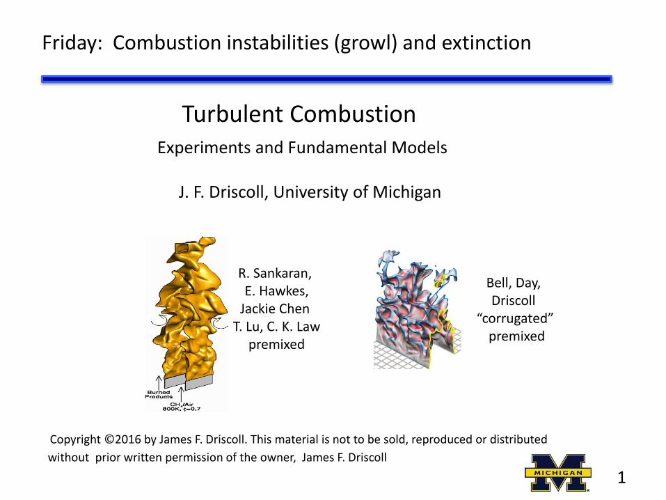
b) What is the physical mechanism causing instability ? Standing waves ? Helmholtz ? Vortex shedding ?
2. Problem: NOx and combustion instability
a) We cannot predict how lean - before the beginning of instability - instability occurs when damping less than driving mechanism
c) CFD of instability not yet satisfactory (V. Yang, Menon, Ihme) Reduced model can be done (Lieuwen, Ghoniem)
d) What measurements needed to improve the model ? kilohertz imaging of flame, flow velocity
8

Research issue: scaling laws for larger/smaller combustors
21 cm
Cylindrical combustor
Fuel injector
FlowStraightener
Quartz windows
400 kW, air flow =0.25 kg/s 15 atm. pressure 700 K preheated air syngas, natural gas, Jet-A fuel Lean premixed technology
9
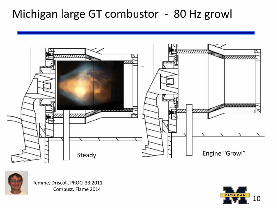
Michigan large GT combustor - 80 Hz growl
Steady
Temme, Driscoll, PROCI 33,2011 Combust. Flame 2014
Engine “Growl” Steady
10

Unstable - when flame base is lifted too far
Recirculation
zone
Pilot Flame
(non-premixed)
MAIN Flame
(premixed)
Pilot air
Pilot fuel
Main
air
Main
fuel
GE TAPS
11

Measured frequencies
Pressure
Liftoff height Flame intensity
Power Spectral density
0 100 200 300 Frequency Hz
12
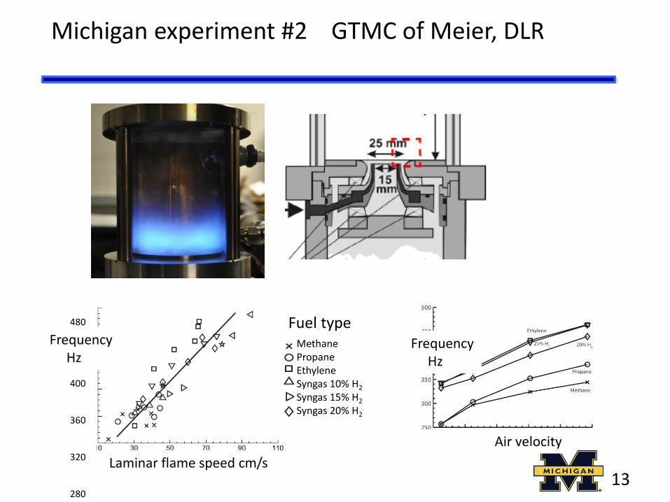
480 400 360 320 280
Frequency Hz
Laminar flame speed cm/s
Methane Propane Ethylene Syngas 10% H2
Syngas 15% H2
Syngas 20% H2
Fuel type Frequency Hz
Air velocity
Michigan experiment #2 GTMC of Meier, DLR
13

What is the physical mechanism causing growl ?
Organ tones = standing waves ? Helmholtz resonance ? Vortex shedding ? Fuel feed line instability ?
U. Cambridge Ecole Centrale Paris Georgia Tech U. Michigan
14

Proof that “growl” is a Helmholtz resonance
plenum combustor
D x (cm)
1.0 0.5 0.0
-8 -4 0 2
only a Helmholtz resonator has this correlation function
15

What is the physical mechanism causing growl ?
8
Helmholtz resonator but with a flame
“forcing function”
Flame Attached
Vortex Puff - flame lifted - combustor pressure rises - orifice velocity + Liftoff region
fills with reactants
Flame flashback acts like a piston - -combustor pressure decreases -orifice velocity negative 16

17
Helmholtz resonator = simple harmonic oscillator = 2nd order ODE
Conservation of mass, energy and momentum
Convert density (r) to pressure using r = p /RT Convert energy to temperature using e2 – e1 = cv (T2-T1) Combine conservation equation eliminate velocity, get 2nd order ODE for p’
Harmonic oscillator with damping z
and natural frequency
wc = c (A(/V L))1/2

which submodel for heat release is best ?
A B C
Yuntao Chen J. F. Driscoll (submitted)
18
Plenum volume + combustor volume + a flame = DRIVEN harmonic oscillator = two coupled differential equations

Three key questions
1. When is acoustic damping term overcome by forcing term ? instability first occurs 2. What is damping term ?
3. Which submodel best for heat release term ?
A B C
19

1 spectrum of flame surface density oscillations – kHz PLIF
2 spectrum of velocity fluctuations kHz PIV
What kilohertz laser measurements - to answer three key questions ?
3 phase angle of pressure - heat release (Rayleigh index)
4 phase angle of velocity – heat release (phase avg PIV)
5 time delay t is it convective time h / U ?
6 which of three submodels of heat release term is best ? 7 what is the acoustic damping ? 20

Measure phase-averaged velocity
air velocity pulses with pressure phase angle
60o 90o
210o 240o 270o
21

Measured phase angle of heat release rate
Phase angle of heat release
(Rayleigh index)
from kilohertz PLIF
air velocity oscillations
phase angle of pressure
0 90 180 270 360o
Phase angle of velocity oscillations
from PIV
22

Measured phase angles - compare to theory
Conclude: submodel “A” for heat release term gives good agreement with measured frequencies, phase angles
Combustor pressure Plenum pressure Inlet velocity Flame liftoff distance Heat release rate
time
f1 = 63o
f3 = 180o
f2 = 150o
F4=300o time lag t
23

Measure phase angle – of heat release - kHz PLIF
Quantronix Hawk laser 355 nm 4,000 /sec
Phantom v711 camera Burner
24

Flame and pressure - have periodic oscillations
Pressure spectrum
25

spectrum of flame surface density oscillations
mean flame surface density
Flame surface density - from kHz formaldehyde PLIF
26

Chemiluminescence - pulsing at 310 Hz
27

Rayleigh criterion –we must know where flame is located
Velocity (PIV) Formaldehyde gradient
flame surface density
28

Measurements determine the best submodel
damped harmonic oscillator submodel A = best for heat release flucts.
Solution to this ODE is in agreement with our measurements
Allison et al.
PROCI 35, 2014
480 400 360 320 280
Frequency Hz
Laminar flame speed cm/s
Methane Propane Ethylene Syngas 10% H2
Syngas 15% H2
Syngas 20% H2
Fuel type
Model Predicts: Flame speed Gas velocity Speed of sound
29

Model explains several of the measured trendsl
Frequency of instability (Hz)
Mass flow rate
Model predicts a trend that agrees with the experiment
30

Lean premixed combustion is important for the future low NOx, CO, soot; power from natural gas, synfuel
Concluding remarks
Reduce NOx
Avoid Combustion Instability
Fuel flexibility
“Growl” combustion instabilities depend on: fuel type, flame speed, fuel-air, flow velocity, pressure, geometry syngas instability more likely and more severe (for H2 < 20%)
Model was developed for one simple geometry measured phase angles, damping, heat release, spectra, kHz PLIF
model predicts measured trends
Still need: CFD-LES for realistic geometries Predict onset of instabilities
31

Ways to avoid instabilities - to reduce NOx by operating leaner
• Anchor - the premixed “main” flame better, more H2
• Change the location of fuel injection
• Add friction - (damping, Dp ) to smallest air orifices
• Alter wall geometry to avoid acoustic resonance
32

What causes distributed reactions ?
GT Combustor: Meier
small mean velocity = merging large residence time preheated reactants
flamelets + distributed
HCCI: Alden zero mean velocity large residence time preheated reactants fully distributed
MILD combustion – Industrial furnace
Preheated reactants strong recirculation large residence time fully distributed ?
33

Are distributed reactions at High Reynolds number ?
Turbulence intensity
Turbulence integral scale lI / dflame
thick flamelets
corregated flamelets
thin flamelets
thick preheat
Klimov-Williams
Large Karlovitz number (u’ / lI ) Large u’ but Small integral scales Broken Flamlets ?
Large Reynolds number ReT = u’ lI / n
Large u’ and Large integral scales Distributed Reactions ?
34

35
How to achieve “distributed reaction zones”
Cannot use room Temp. reactants - flame extinguishes before eddies enter reaction zone 1. HCCI: use piston to rapidly heat to T > Tig
2. Highly pre-heated burners: Preheat air to T> Tig , rapidly mix in fuel Create large strain to lift flame for good premixing Examples: Berkeley Cabra burner Ramjet: jet in preheated crossflow
Mach 0.7
1500 K
air
C2H4 fuel CH2O
auto-ignition
region
OH heat
release 700 K
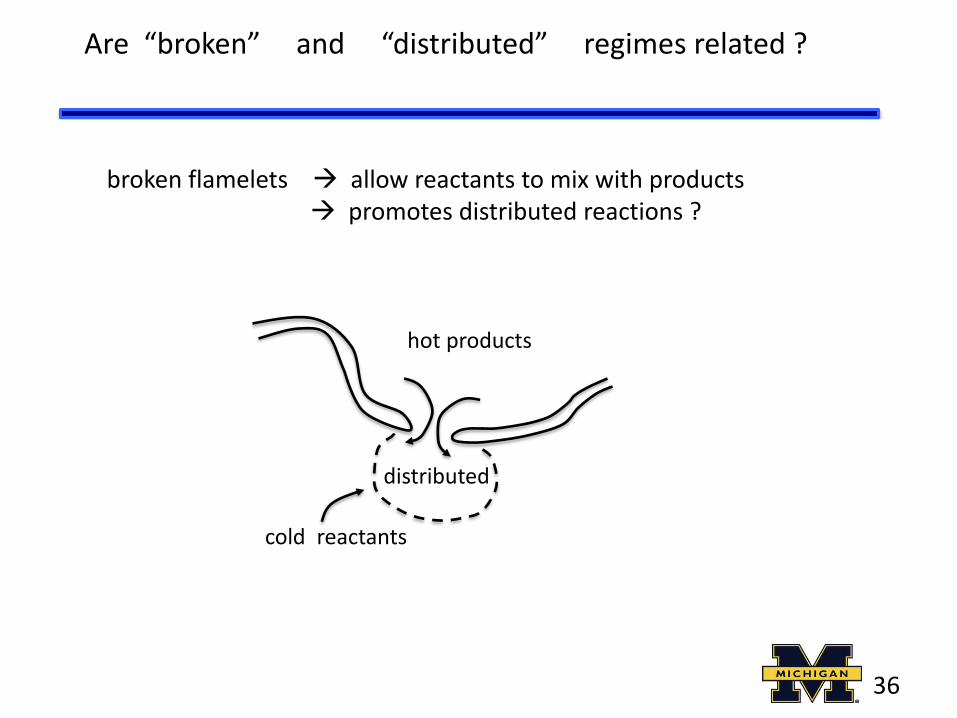
broken flamelets allow reactants to mix with products promotes distributed reactions ?
Are “broken” and “distributed” regimes related ?
hot products
cold reactants
distributed
36

37

38

39
MILD / flameless combustion regimes Wunning and Wunning
FLAMELESS OXIDATION TO REDUCE THERMAL NO-FORMATION J. A. Wunning and J. G. Wunning, Prog. Energy Combust Sci.23, 81. MILD COMBUSTION, Antonio Cavaliere, Prog. Energy Combust Sci 30, 329 temperature peaks can be avoided thermal NO-formation is suppressed Flameless = high air preheat + strong recirculation of exhaust gases (EGR) MILD = moderate or intense low-oxygen dilution

40
MILD Combustor of N. Peters
LASER OPTICAL INVESTIGATION OF HIGHLY PREHEATED COMBUSTION WITH STRONG EXHAUST GAS RECIRCULATION, T PLESSING,N PETERS, J WUNNING PROCI 27, p. 3197
Achieve a well-stirred reactor: Wall temperatures must be kept above 800 C Strong recirculation since flow goes up on centerline, down near walls Low air dilution: Exhaust gases exit furnace and are cooled in heat exchanger then mixed with air and forced back into furnace Air preheat by the EGR mixed with the air NOx drops to one-third of its initial value it had before recirculation and preheating

41
Low NOX strategies of GE and Pratt
Turbofan engine NOx ratings: NOx = NO + NO2 nitric oxide + nitrogen dioxide 100 ppm is lethal NOx emission index: EINOX = (50 grams/sec NOx)/( kg/sec fuel) Specific emission index: (0.5 grams/sec NOx) / (kN thrust) NOx cycle: NO produced in engine where T > 1700 K and lean, NO2 not produced in engine, but later O2 + N2 2 O + N Oxygen molecule dissociates at high temperature O + N2 NO + N Zeldovich thermal NO formed in engine N + O2 NO + O Zeldovich thermal NO formed in engine NO + O2 NO2 + O photochemical smog (NO2) produced in atmosphere NO2 + O2 NO + O3 ozone (O3) produced at lower altitudes (BAD) NO + O3 NO2 + O2 ozone (O3) destroyed at upper altitudes in ozone layer (BAD) NO2 + H2O HNO3 + H acid rain falls on plants (BAD) but scrubs NO2 out of air (GOOD)

42
Assume lean combustion (f = 0.8) of Jet-A (C10H20), products are: CO2, H2O, O2, N2
Assume a residence time of 30 msec, dilution air is six times primary air
C10 H20 + 18.75 O2 + 18.75 (79/21) N2 10 CO2 + 10 H2O + 3.75 O2 + 18.75 (79/21) N2 XN2 = 0.75, XO2 = 0.04, T = 2200 K [N2] = XN2 p /(RuT) = 61.5 mol/m3 [O2] = XO2 p /(RuT) = 3.3 mol/m3 Then: [NO] = 3.1 x 10⁻⁴ mol/m3
so XNO = 1200 ppm, dilute with air to 200 ppm in exhaust

43
NOx Strategies
GE: LPP = lean premixed prevaporized = TAPS = twin annular premixed swirler Pratt: RBQQ = rich burn, quick quench (stratified) Industrial: Staged combustion – inject fuel in many optimum locations EGR - exhaust gas recirculation after gas is cooled After treatment (for ground based power) catalytic converter (platinum), ammonia reburn NH3 NH + H2, NH + CH4 HCN + 2 H2, HCN + NO N2 + HCO

44
Recirculation
zone
Pilot Flame
(non-premixed)
MAIN Flame
(premixed)
Pilot air
Pilot fuel
Main
air
Main
fuel
GE TAPS
LPP = lean premixed prevaporized GE TAPS
Used in GEnX engine in Boeing 787 Lower NOx, better fuel economy Designed entirely by trial and error, not CFD Has a growl problem at certain conditions, but don’t go there !

45
RBQQ of Pratt and Whitney = rich burn, quick quench
Idea: reduce the residence time (Dt) of gas in the “near stoichiometric” zone In the primary zone, fuel and air burn rich, then as dilution air is added through the liner walls the gases are accelerated to quickly pass through the stoichiometric region Then they pass into the lean region where is is below 1700 K and no more NOx is produced
Dilution air
Primary air Primary
fuel
Rich primary combustion
f = 0.9 “ Nearly stoichiometric zone”= high gas velocity
Lean, cooler Dilution zone
Rich primary zone = good flame stability Rapid velocity in near stoichiometric zone = low NOx Long residence time in lean dilution zone = low CO

46
RBQQ = rich burn quick quench

47
Staged Combustors and EGR
fuel
air
T = 1700 K lean isotherm All NOx is produced in grey region between these two isotherms
T = 2200 K stoichiometric isotherm
EGR: extract some of the products, remove their heat and re-use this energy to heat up the incoming air, then inject the cool, inert products into the hot zone shown above to reduce the local temperature to reduce NOx
rich lean
Staged combustion: add pipes that inject fuel or air or cooled exaust products at optimized locations to reduce the size of the NOx formation region


![Fundamental studies of premixed combustion [PhD Thesis]](https://img.pdfslide.us/doc/110x75/563db7e7550346aa9a8f0c44/fundamental-studies-of-premixed-combustion-phd-thesis.jpg)