Embed Size (px)
Citation preview

Effects of Flow Field on Diffusion Flame Structure
T. Takeno, M. Nishioka and H. YamashitaDepartment of Mechanical Engineering, Nagoya University
Chikusa-ku, Nagoya, 464-01 Japan
ABSTRACT
A laminar diffusion flame may be established in a variety of flow fields and the flame structure, comprisedof a thin reaction zone and outer diffusion layers of fuel and oxidizer, may depend on the specific flowfield in which the flame is established. In the present study the characteristic diffusion time of the outerdiffusion layer was proposed as a linkage parameter to describe effects of the flow field on the diffusionflame structure, and a numerical study was made to test this proposal for stable flames that do not lead tolocal extinction. The fuel and oxidizer adopted were methane and air, respectively, and the calculationwas done with detailed chemical reaction mechanisms of C2 chemistry. The flames studied were threecounterflow flames and one axisymmetric coflow flame. The former are an axisymmetric counterflowflame, a rectangular counterflow flame and a tubular counterflow flame, and can be described in terms ofthe similarity solution, which makes the calculation into a relatively simple 1D calculation. On the otherhand, the calculation of the coflow flame requires a time-consuming 2D calculation, and a newlydeveloped 2D-Code, with an adaptive mesh adjusted for flame structure, was used. The complete ellipticpartial differential equations were solved so as to account for the exact effects of a dead space formed atthe leading edge of the flame. The study has revealed that there is a remarkable similarity in the structureof the diffusion flames in different flow fields with the same diffusion time. The agreement of moleproduction rate profiles is more excellent than those of temperature and concentration profiles. It has beenshown that the diffusion time not only governs the structure of the outer diffusion layer but also controlschemical reactions proceeding inside the reaction zone, and is the most appropriate parameter to describethe effects of a flow field on the diffusion flame structure.
INTRODUCTIONWhat is a laminar diffusion flame? Any laminar flames in which the fuel and oxidizer are initiallyseparated are called diffusion flames. In this definition, we may more appropriately call the flame alaminar nonpremixed flame. In the non-premixed flame, however, most of the chemical reaction occurs ina narrow reaction zone that can be approximated as a surface. The structure suggests that the combustionrate of the flame is controlled by supply rates of fuel and oxidizer to the reaction zone by moleculardiffusion. This is the reason why we call the laminar nonpremixed flame a diffusion flame. The diffusionflame may be established in a variety of flow fields and the flame structure may depend on the specificflow field in which the flame is established. How can we describe this effect, and is there any chance ofdescribing it in a universal manner ? This is the problem to be answered in this study.
The asymptotic analysis of the flame suggests that the diffusion flame structure in any flow field iscomprised of a thin reaction zone and outer diffusion layers of fuel and oxidizer, surrounding the reactionzone [1]. We proposed that the characteristic diffusion time of the outer diffusion layer can be used todescribe the effects of the flow field [2-4]. This is based on the following idea [3]. In the speciesconservation equation, the contribution of the convective term is not important in the thin reaction zoneand chemical reaction is balanced by molecular diffusion. In the outer diffusion layers, on the other hand,molecular diffusion is balanced by convection. Then the local flow field can affect the flame structure onlythrough the convection in the outer diffusion layers, and will determine concentration distributions in thediffusion layers. The concentration gradients at the boundary between the diffusion layer and the reactionzone are determined accordingly. The gradient can be used to evaluate the characteristic diffusion time ofthe diffusion layer. In addition, it will control what happens in the reaction zone through the supply rate ofreactants to that zone. This is the reason why we can make use of the characteristic diffusion time as alinkage parameter to link diffusion flames in different flow fields.
In the present study we try to test the above proposal for stable flames that do not lead to localextinction. A numerical approach is most convenient, provided that calculations with detailed chemicalreaction mechanisms can be implemented, since we can make use of numerical experiments [3] tocompare the detailed flame structure in different flow fields for identical values of the diffusion time. Somesimilar attempts have already been made in the past [5-9] on the basis of the laminar flamelet model [10].The scalar dissipation rate, instead of the diffusion time, was used as a linkage parameter, and thecomparison of flame structure was made in the phase space of concentration vs. mixture fraction. Thescalar dissipation rate is essentially the same quantity as the diffusion time, as it is just the inverse of thediffusion time. However, we believe that the concept of a diffusion time, based on the flame structure in

physical space, is much easier to understand. In addition, we believe that the physical implications of theconcept have not yet fully been made clear. In diffusion flames in general, the concentration distributionsin the outer diffusion layers may still depend on the local flow field even for matched values of a linkageparameter. What we can expect more generally is the similarity of reaction rates in the narrow reactionzone, being independent of the flow field, since the diffusion time determines the supply rate of reactants.In this sense, the comparison of mole production rates in the physical plane is essential [16].
NUMERICAL MODELThe fuel and oxidizer adopted were methane and air, respectively, at atmospheric pressure. Thethermochemical parameters and transport properties were calculated using CHEMKIN. Thermal diffusionwas considered only for H and H2. The chemical reaction mechanism adopted was the so-called C2chemistry, compiled by Miller and Bowman [11], including the prompt and thermal NO formationmechanisms. It involves 52 species and 235 elementary reactions. In the present study the characteristicdiffusion time was defined in the following way [2]. To begin with, the apparent reaction zone position wasdefined as the position where the local heat release rate becomes maximum. The concentration gradient atthis position was adopted to approximate that of the boundary between the reaction zone and the diffusionlayer. The conserved scalar Z was defined by the normalized concentration of N2 to give values of unityand 0 for fuel and oxidizer, respectively. The local scalar dissipation rate Χ q was defined by the gradient ofZ normal to the reaction zone at the apparent reaction zone position by
Χq = Dq | ∇ Z |q2,
where Dq is the representative diffusion coefficient at the apparent reaction zone position. Thecharacteristic diffusion time tD is the inverse of the scalar dissipation rate and is given by
tD = 1/Χ q .
The flames studied were three counterflow diffusion flames and one axisymmetric coflow diffusion flame.The former are an axisymmetric counterflow flame, a rectangular counterflow flame and a tubularcounterflow flame, and can be described in terms of a similarity solution, which reduces the governingequations to ordinary differential equations and makes the numerical calculation relatively simple. Thenumerical models of the three flames are shown schematically in Fig. 1. The temperatures of the injectedmethane and air were room temperature, 300 K. For the axisymmetric flame, the nozzle distance L was 1.5cm and 3.0 cm, and the fuel and air injection velocities uF and uo were kept equal and were changed from5 to 180 cm/s. Some calculations were made while keeping uF at 16 cm/s and changing uo from 8 to 32cm/s. L was kept at 1.5 cm for the rectangular flame, and uF and uo were kept equal and changed from 5 to60 cm/s. In the tubular flame, the fuel was injected from the inner cylinder surface and the air from theouter cylinder surface. The calculation was done for two sets of the cylinder radius: 0.5 cm inner and 2.0cm outer, and 1.5 cm inner and 3.0 cm outer. uF and uo were kept equal and changed from 10 to 60 cm/s.The calculation of these flames was done in the same way as in the previous studies [12-15] by using amodified CHEMKIN 1D-Code.
Figure 1 Numerical models of three counterflow diffusion flames; left, axisymmetric flame, center,rectangular flame, right, tubular flame.

On the other hand, the numerical model and boundary conditions of the coflow diffusion flame areshown in Fig. 2. The fuel injector radius was 0.2 cm, and the fuel at room temperature was injected inparallel to the surrounding air flow with a fully developed velocity distribution.
Figure 2 Numerical model and boundary conditions of axisymmetric coflowing diffusion flame.
The average injection velocity was 50 cm/s. The air at room temperature was injected at 0.5 cm upstreamof the injector exit with a uniform velocity of 50 cm/s. A boundary layer develops naturally along theinjector outer wall which has zero thickness. The injector wall temperature was set to 700 K, which is thevalue measured experimentally by the present authors. The calculation of flame structure requires a time-consuming 2D calculation, and a newly developed 2D-Code, with an adaptive mesh adjusted for flamestructure, was used [16]. The complete elliptic partial differential equations were solved so as to accountfor the exact effects of a dead space formed at the leading edge of the flame.
RESULTS OF CALCULATION
1. COMPARISON OF THREE COUNTERFLOW FLAMESFigure 3 shows the relation between the aerodynamic time ta and tD calculated for the three counterflowflames. The former was defined by L/(uF + uo), and is just the inverse of the more familiar velocity gradient.As is seen in the figure, there exists a universal relationship between ta and tD common to the threecounterflow flames. The relationship is independent of flame configuration, nozzle distance and fuel andair injection velocities, and gives a one-to-one correspondence between the velocity gradient and theproposed characteristic diffusion time.
Figure 4 compares the flame structure of axisymmetric flames for three combinations of L , uF and uo,with the same value of ta. Profiles of temperature T and mole fraction Xi of main species are compared. Thesimilarity of the three flame structures is remarkable, and we see that the flame structure is mostlydetermined by ta, or by tD , being independent of L, uF and uo. On the other hand, the calculated structure ofthe three types of flame changed with tD ; the flame thickness becomes larger and larger with an increase intD , while keeping similar temperature and concentration profiles of the main species. However, when acomparison was made of the structure of three type flame for identical values of tD , it was found that thereis a remarkable similarity in the structure, as will be seen clearly in Figs. 6-9 shown later.

Figure 3 Correlation of aerodynamic time ta with diffusion time tD of three counterflow diffusion flames.
Figure 4 Comparison of flame structure of axisymmetric counterflow flame for three combinations ofnozzle distance L , fuel injection velocity uF and air injection velocity uo, with same value ofaerodynamic time ta = 31.3 ms.

It may be said, therefore, that the structure of counterflow flames is governed by the proposed diffusiontime being independent of the flame configuration, nozzle distance and fuel and air injection velocities. Inview of the fact that there is a one-to-one correspondence between the diffusion time and the velocitygradient, we may use either of them to characterize the flame structure. However, the flow fields of thethree counterflow flames are very similar by origin, and the above result may be regarded as just thenatural consequence of this similarity. The problem is, therefore, how these counterflow flame structurescorrelate with that of the coflow flame.
2. COMPARISON OF COFLOW FLAME WITH COUNTERFLOW FLAMES
Figures 5a-5d show the calculated coflow diffusion flame structure [16]. Distributions of temperature, NOmole fraction, NO2 mole fraction and NO molar production rate are shown, respectively. In the figures theapparent flame surface, defined by a locus of the peak in local heat release rate profile, is described by asolid line. Note that the r-axis in Fig. 5d is expanded for clearness. As is seen in Figure 5a the flame isstabilized at an upstream point near the exit along the outer wall of the injector. From this attachmentpoint the diffusion flame develops downstream expanding in the radial direction. The characteristic featuresof the flame are discussed elsewhere [16] and hence the description is abbreviated here. In the following,this flame structure along the coordinate normal to the apparent flame surface is compared with those ofthe previous counterflow flames. The comparison was made at the three representative points along theflame surface, corresponding to tD = 0.842 s, 1.76 s and 2.98 s, as shown in Fig. 5a.
Figure 5.1 Flame structure of coflowing diffusion flame with apparent flame surface represented by solidline: distributions of (a) temperature and (b) NO.

Figure 5.2 Flame structure of coflowing diffusion flame with apparent flame surface represented by solidline: distributions of (c) NO2 concentration and (d) NO production rate.
Figures 6-9 compare the upstream flame structures at tD = 0.842 s with those of the three counterflowflames with same value of tD . The origin of the space coordinate n is the peak position of the heat releaserate, and the solid line and the three dashed lines correspond to the coflow flame and the counterflowflames, respectively. Figure 6 shows that the temperature and the major species concentration distributionsof the four flames agree remarkably well, although some slight discrepancies are observed at their skirts onthe fuel side.
Figure 6 Comparison of flame structure of four flames with same value of diffusion time tD = 0.842 s;profiles of temperature and mole fractions of major species.

The distributions of minor species are compared as well in Fig. 7. As is seen in the figure, theconcentrations in the coflow flame are slightly lower than those in the counterflow flames, except for theCH concentration for which the agreement is perfect. The appearance of an NO2 distribution on the fuelside of the coflow flame, is the result of leakage of O2 into the fuel stream through the dead space at theleading edge [16].
Figure 7 Comparison of flame structure of four flames with same value of diffusion time tD = 0.842 s;profiles of mole fractions of minor species.
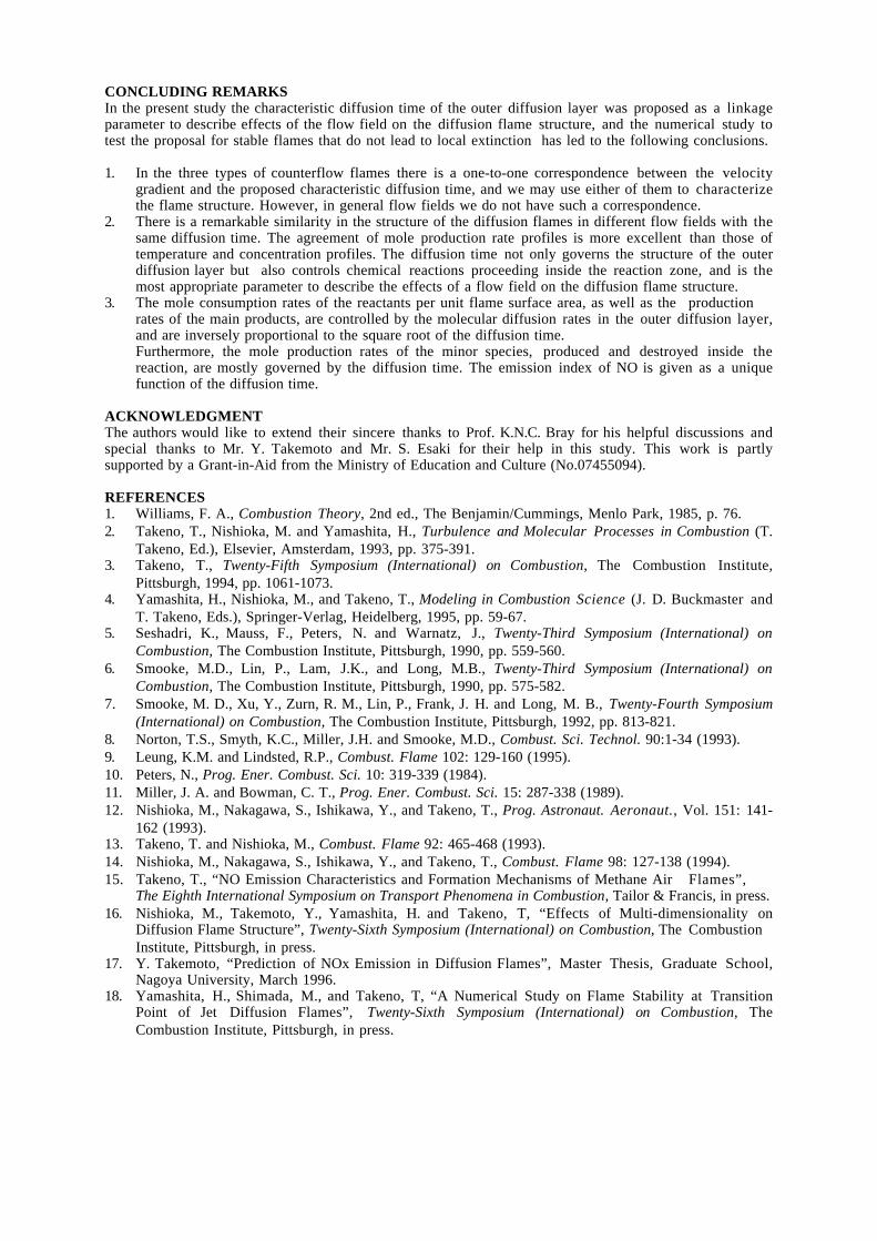
Figures 8 and 9 compare the mole production rate profiles of main and minor species, respectively.Although some slight discrepancies in the peak values are observed, the agreement of the profiles is almostperfect, and we notice that the agreement of the mole production rate profiles is better than that of theconcentration profiles. Comparison of the middle- and down-stream flame structures with those of thecounterflow flames was also made [17].
The reaction zone, as well as the outer diffusion layers, are expanded downstream, and thediscrepancies in the temperature and concentration profiles increase slightly. The latter is presumably dueto the fact that the contribution of the convective term becomes somewhat more important in the expandedreaction zone. However, the general trend is identical with that described above, and the agreement of theflame structure is remarkable here again. This agreement suggests that tD is an appropriate parameter tolink diffusion flames in different flow fields.
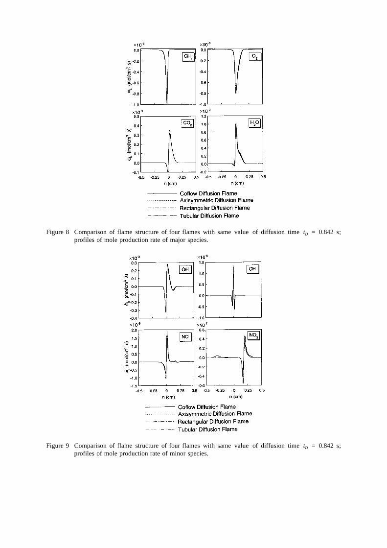
Figure 8 Comparison of flame structure of four flames with same value of diffusion time tD = 0.842 s;profiles of mole production rate of major species.
Figure 9 Comparison of flame structure of four flames with same value of diffusion time tD = 0.842 s;profiles of mole production rate of minor species.

Figure 10 compares the distributions of flow velocity normal to the apparent flame surface for the threevalues of tD . Please notice that the velocity component parallel to the surface has no effects on the flamestructure. As is seen in the figure, there is a definite similarity among the distributions in the threecounterflow flames, and also there is a certain similarity in the general trend of the counterflow flames andof the coflow flame. However, the discrepancy between the two types of flame is so large that it is almostimpossible to introduce any common parameters, such as the velocity gradient or stretch, to correlate theflow field of the coflow flame with that of the counterflow flames. We must give up the idea ofcharacterizing the flame structure in terms of simple flow parameters. On the other hand, the proposeddiffusion time includes effects of the local flow field, in addition to those of molecular diffusion, and webelieve that this is the most appropriate parameter to link the diffusion flame structures in different flowfields.
Figure 10 Comparison of the distribution of flow velocity normal to the apparent flame surface of coflowflame (solid line) and three counterflow flames (dashed lines) for three different diffusion timetD .
3. MOLE PRODUCTION RATE AND NO EMISSION INDEX
The excellent agreement of mole production rates profiles, not only of major species but also of minorspecies, suggests that chemical reactions proceeding in the narrow reaction zone are actually controlled bythe supply rates of reactants to the zone by molecular diffusion. This can be seen clearly in Figs. 11 and12, in which mole production rates per unit flame surface area of major and minor species, respectively,are shown as a function of tD for the four flames. The mole production rate is obtained by integrating moleproduction rate per unit volume along the space coordinate n. As is seen in Fig. 11, the mole productionrates of major species are unique functions of τD , being independent of the flame type. They are inverselyproportional to the square root of tD . These species are the reactants supplied to, or the products taken awayfrom, the reaction zone by molecular diffusion Their consumption or production rates are governed by themolecular diffusion rates in the outer diffusion layers, rather than by the reaction rates in the reaction zone.The molecular diffusion rate is directly proportional to the concentration gradient, and hence is inverselyproportional to the square root of tD by definition.
On the other hand, the minor species shown in Fig. 12 are produced and destroyed inside the reactionzone alone, and their production rates should depend in a complicated way on the chemical kineticsproceeding inside the reaction zone. However, the fair agreement between the four flames suggests that theultimate production rate is mostly governed by the supply rate of the original reactants such as CH4 and

O2. That is, what happens inside the reaction zone is mostly governed by the supply rates of the reactantsto that zone, and the local flow field affects this only through tD . This gives further evidence that tD is themost appropriate parameter to represent the effects of the local flow field on the diffusion flame structure. Itis interesting to note that the NO production rate is rather insensitive to tD and remains almost constant in awide range of tD . The combination of the production rate of NO and the consumption rate of CH4 gives theemission index of NO, that is mass production of NO per unit mass consumption of CH4. The result isshown in Fig. 13. The agreement of the four flames suggests that this curve gives a universal relationshipcommon to all diffusion flames. We can make use of this relationship to predict the NO emission index ofany type of laminar diffusion flame.
Figure 11 Mole production rates per unit flame surface area of major species as functions of characteristicdiffusion time tD for four type flames.
Although the computational domain used in this study does not cover the whole flame, and the resultsobtained are limited to the upstream half of the coflow diffusion flame and we have to continue furtherstudies, the implication of the results so far obtained should be very important [16]. If we adopt anappropriate linkage parameter, such as the representative diffusion time, we can make use of thecounterflow diffusion flame calculation to predict the essential characteristics of diffusion flames in otherflow fields which do not lead to local extinction. Another crucial problem is the prediction of localextinction. Although the present study is concerned only with the stable flame structure, there is a chancethat the proposed diffusion time can be used to predict the local extinction in general flow fields in just thesame way as the critical scalar dissipation rate [10]. In general, the extinction of laminar diffusion flameshas so far been discussed in terms of the velocity gradient, or the stretch rate. As is shown in Fig. 10,however, the velocity gradient is not an adequate parameter to describe effects of the local flow in generalflow fields. It is more reasonable to adopt the critical diffusion time to predict the local extinction. In factwe have proposed this concept in our recent paper on the local extinction of jet diffusion flames [18].

Figure 12 Mole production rates per unit flame surface area of minor species as functions of characteristicdiffusion time tD for four type flames.
Figure 13 NO emission index of four type flames as a function of characteristic diffusion time tD .
CONCLUDING REMARKSIn the present study the characteristic diffusion time of the outer diffusion layer was proposed as a linkageparameter to describe effects of the flow field on the diffusion flame structure, and the numerical study totest the proposal for stable flames that do not lead to local extinction has led to the following conclusions.
1. In the three types of counterflow flames there is a one-to-one correspondence between the velocitygradient and the proposed characteristic diffusion time, and we may use either of them to characterizethe flame structure. However, in general flow fields we do not have such a correspondence.
2. There is a remarkable similarity in the structure of the diffusion flames in different flow fields with thesame diffusion time. The agreement of mole production rate profiles is more excellent than those oftemperature and concentration profiles. The diffusion time not only governs the structure of the outerdiffusion layer but also controls chemical reactions proceeding inside the reaction zone, and is themost appropriate parameter to describe the effects of a flow field on the diffusion flame structure.
3. The mole consumption rates of the reactants per unit flame surface area, as well as the productionrates of the main products, are controlled by the molecular diffusion rates in the outer diffusion layer,and are inversely proportional to the square root of the diffusion time.Furthermore, the mole production rates of the minor species, produced and destroyed inside thereaction, are mostly governed by the diffusion time. The emission index of NO is given as a uniquefunction of the diffusion time.
ACKNOWLEDGMENTThe authors would like to extend their sincere thanks to Prof. K.N.C. Bray for his helpful discussions andspecial thanks to Mr. Y. Takemoto and Mr. S. Esaki for their help in this study. This work is partlysupported by a Grant-in-Aid from the Ministry of Education and Culture (No.07455094).
REFERENCES1. Williams, F. A., Combustion Theory, 2nd ed., The Benjamin/Cummings, Menlo Park, 1985, p. 76.2. Takeno, T., Nishioka, M. and Yamashita, H., Turbulence and Molecular Processes in Combustion (T.
Takeno, Ed.), Elsevier, Amsterdam, 1993, pp. 375-391.3. Takeno, T., Twenty-Fifth Symposium (International) on Combustion, The Combustion Institute,
Pittsburgh, 1994, pp. 1061-1073.4. Yamashita, H., Nishioka, M., and Takeno, T., Modeling in Combustion Science (J. D. Buckmaster and
T. Takeno, Eds.), Springer-Verlag, Heidelberg, 1995, pp. 59-67.5. Seshadri, K., Mauss, F., Peters, N. and Warnatz, J., Twenty-Third Symposium (International) on
Combustion, The Combustion Institute, Pittsburgh, 1990, pp. 559-560.6. Smooke, M.D., Lin, P., Lam, J.K., and Long, M.B., Twenty-Third Symposium (International) on
Combustion, The Combustion Institute, Pittsburgh, 1990, pp. 575-582.7. Smooke, M. D., Xu, Y., Zurn, R. M., Lin, P., Frank, J. H. and Long, M. B., Twenty-Fourth Symposium
(International) on Combustion, The Combustion Institute, Pittsburgh, 1992, pp. 813-821.8. Norton, T.S., Smyth, K.C., Miller, J.H. and Smooke, M.D., Combust. Sci. Technol. 90:1-34 (1993).9. Leung, K.M. and Lindsted, R.P., Combust. Flame 102: 129-160 (1995).10. Peters, N., Prog. Ener. Combust. Sci. 10: 319-339 (1984).11. Miller, J. A. and Bowman, C. T., Prog. Ener. Combust. Sci. 15: 287-338 (1989).12. Nishioka, M., Nakagawa, S., Ishikawa, Y., and Takeno, T., Prog. Astronaut. Aeronaut., Vol. 151: 141-
162 (1993).13. Takeno, T. and Nishioka, M., Combust. Flame 92: 465-468 (1993).14. Nishioka, M., Nakagawa, S., Ishikawa, Y., and Takeno, T., Combust. Flame 98: 127-138 (1994).15. Takeno, T., “NO Emission Characteristics and Formation Mechanisms of Methane Air Flames”,
The Eighth International Symposium on Transport Phenomena in Combustion, Tailor & Francis, in press.16. Nishioka, M., Takemoto, Y., Yamashita, H. and Takeno, T, “Effects of Multi-dimensionality on
Diffusion Flame Structure”, Twenty-Sixth Symposium (International) on Combustion, The CombustionInstitute, Pittsburgh, in press.
17. Y. Takemoto, “Prediction of NOx Emission in Diffusion Flames”, Master Thesis, Graduate School,Nagoya University, March 1996.
18. Yamashita, H., Shimada, M., and Takeno, T, “A Numerical Study on Flame Stability at TransitionPoint of Jet Diffusion Flames”, Twenty-Sixth Symposium (International) on Combustion, TheCombustion Institute, Pittsburgh, in press.