Embed Size (px)
Citation preview
J. Fluid Mech. (1996), vol. 329, pp. 389-411
Copyright © 1996 Cambridge University Press 389
Flow field of a diffusion flame attached to a thick-walled injector between two coflowing
reactant streams By F. J. H I G U E R A AND A. L I Ñ Á N
ETS Ingenieros Aeronáuticos, Pza. Cardenal Cisneros 3, 28040 Madrid, Spain
(Received 2 October 1995 and in revised form 30 July 1996)
The flow field of a diffusion flame attached to a thick-rim injector between two coflowing streams of fuel and oxidiser is analysed in the Burke-Schumann limit of infinitely fast reaction rate. The length of the recirculation región immediately behind the injector and the velocity of the recirculating fluid are proportional to the shear stresses of the reactant streams on the wall of the injector for a range of rim thicknesses, and the structure of the flow in the wake depends then on three main non-dimensional parameters, measuring the gas thermal expansión due to the chemical heat reléase, the air-to-fuel stoichiometric ratio of the reaction, and the air-to-fuel ratio of wall shear stresses. The recirculation región shortens with increasing heat reléase, and the position of the fíame in this región depends on the other two parameters. An asymptotic analysis is carried out for very exothermic reactions, showing that the región of high temperature around the flame is confined by neatly defined boundaries and the hot fluid moves like a high-velocity jet under a favourable self-induced pressure gradient. The immediate wake is surrounded by a triple-deck región where the interacting flow leads to an adverse pressure gradient and a reduced shear stress upstream of the injector rim for sufnciently exothermic reactions. Separation of the boundary layers on the wall of the injector, however, seems to be postponed to very large valúes of the gas thermal expansión.
1. Introduction A diffusion flame between a gaseous fuel jet and a stagnant or coflowing gaseous
oxidiser is the central element of many combustión devices. The flame is said to be stabilized or attached to the injector if combustión begins immediately upon the reactants coming into contact and the heat transfer toward the injector is important to the process, whereas it is said to be lifted if a región long compared with the size of the jet's cross-section exists between the injector and the base of the flame. The structure of the flow around an attached flame and the limits within which the flame remains attached are obviously of great practical importance and have been very much studied. Thus the región at the base of an attached flame of methane or hydrogen in air has been experimentally investigated by Robson & Wilson (1969), Kawamura & Asato (1975), Kawamura, Asato & Mazaki (1980), and Takahashi et al. (1984), among others, for a variety of fuel jet shapes and exhaust conditions, including cases with a coflowing air stream around a thin-walled injector. The velocity, temperature and reactants concentration fields were measured, as well as the position of the flame, the heat reléase, and the heat fluxes from the flame to the injector and

390 F. J. Higuera and A. Liñán
to the gas downstream. Models of the lifting mechanism have been proposed based on the idea put forward by Gaydon & Wolfhard (1953) that, even for an attached flame, molecular mixing of the reactants between the injector and the base of the flame leads to a small volume of combustible mixture where a premixed flame front can propágate toward the injector against the flow. A steady attached fíame will exist if the propagation velocity of this front can balance the velocity of the flow. Then a fraction of the heat released at the front is transported downstream, serving as an ignition source for the rest of the flame. If such a balance is not possible in the vicinity of the injector rim, the flame will either lift to an equilibrium position far above the injector or disappear altogether. Importantly, while the flow at the base of a lifted flame is typically turbulent, that in the attachment región is always laminar, even if the jet becomes turbulent further downstream.
The immediate wake of a thick injector rim between two coflowing reactant streams provides the modérate strain rates necessary for a diffusion flame to exist, and also, in the vicinity of the rear stagnation point, the low velocities necessary for a premixed flame to propágate without being blown out by the flow. In addition, depending on the conditions of the reactant streams and the position of the flame, the reverse flow in the recirculation región may also provide an alternative mechanism of flame stabilization that does not depend on the propagation of a premixed flame front. The effect of the injector port thickness was first investigated by Vranos, Taback & Shipman (1968) for the flame between coflowing jets of hydrogen and air, who found that the range of fuel and air velocities over which the flame remains attached is very much enlarged when that thickness is increased. They reported a variety of flame behaviours, including a second type of lift-off in which the flame is locally extinguished at some distance downstream of the injector leaving a residual attached flame, and related the existence of these flames, and of the enlarged stability domain, to the recirculating eddies behind the injector rim and to the high diffusivity of the hydrogen. The same trends were observed by Yoon, Donbar & Driscoll (1994) in more recent experiments on supersonic coflowing jets of hydrogen and air. These authors found that the propagating front at the beginning of their attached flames sits in the outer part of the shear layer between the air and the recirculating fluid, where the flow velocity is larger than the propagation velocity of the corresponding stoichiometric premixed flame, and attributed the existence of a steady front under these conditions to a local excess of enthalpy in the recirculating flow, due to the high diffusion flux of hydrogen toward the partially burnt recirculating fluid. In their experiments with methane-air flames, Takahashi & Schmoll (1990) observed a fhird type of flame lift-off, characteristic of thick injector rims, whereby the upstream end of the flame becomes oscillatory immediately before lifting. They showed experimentally that the oscillations are associated with the end of the flame moving in and out of a recirculation eddy in the wake of the injector rim.
In this paper numerical and asymptotic techniques are used to analyse some of these features in their simplest form. For this purpose we consider an injector of thickness large compared with the quenching distance of the flame, which is the size of the región round the tip of a thin-walled injector affected by heat conduction from an attached flame, but still sufficiently small for the lateral displacements of the reactant streams to be negligible. In this range of thicknesses the oncoming streams are characterized only by the valúes of the shear stresses on the injector wall immediately upstream of its end, and both the length of the recirculation región and the velocity of the recirculating fluid scale with these valúes. In addition, since the emphasis is on the description of the flow field, the chemistry is simplified by

Flow field of an attached flame 391
assuming that the flame is an infinitely thin reaction sheet. This corresponds to the Burke-Schumann limit of infinitely fast reactions in which only two parameters are left to characterize the combustión, namely the air-to-fuel mass stoichiometric ratio and the ratio of heat reléase to thermal enthalpy. The numerical and asymp-totic results presented below show that the second of these parameters aflects very significantly the flow, making the recirculation región shorter than for the corre-sponding isothermal flow and eventually leading to a región of favourable pressure gradients downstream of the recirculation bubble, where a jet-like velocity profile develops in the hot fluid around the flame. The position of the flame in the wake depends mainly on the stoichiometric ratio (that, by this means, also affects the flow) and on the ratio of air to fuel shear stresses. The first of these parameters is determined by the nature of the reactants and their concentrations in the oncom-ing streams, whereas the second depends on the configuration of the injector and the flow rates of the reactants. Though the assumption of infinitely fast reaction is not appropriate to determine the stability limits, because it always leads to an attached flame, a number of qualitative conclusions on the likelihood of the dif-ferent types of flame lift-off are drawn by examining the distributions of velocity and strain rate on the flame and their dependence on the parameters mentioned before.
2. Formulation The flow in the attachment región of the flame is nearly planar, independently of
the shape of the injector, owing to the small size of this región compared to the size of the injector cross-section. As a model of this flow we consider two parallel streams of density pm, temperature T^, and velocities UF and U0 much smaller than the sound speed in either fluid, carrying mass fractions YFx and Y0x¡ of fuel and oxygen, respectively, and separated by a wall of thickness 2h. The two streams can either extend to infinity or be confined to finite-width channels formed by the separating wall and two other plañe parallel walls, or an outer wall and a symmetry plañe. The two streams come into contact at the end of the separating wall, reacting in a flame that releases an energy Q per unit mass of fuel consumed. The chemical reaction is supposed to be infinitely fast, so the flame is a continuous, infinitely thin sheet separating the two reactants, which only coexist in the interior of the flame with infinitely small concentrations (see, e.g., Williams 1985).
Counterflow heat conduction toward the separating wall is important in small regions of size Re"{/2ó about its edges, where the full Navier-Stokes equations should be solved to describe the flow. Here, using for definiteness the conditions of the fuel stream, 5 is the thickness of the fuel boundary layer at the end of the separating wall, or the width of the fuel channel in the case of a developed, parabolic flow (in which case UF and U0 are the mean velocities of the streams), Re = p^U^/n^ is the Reynolds number, which will be assumed to be large, and fi^ is the viscosity coefficient at temperature TOQ. In what follows a h >• Re~1/23 is assumed. Then the balance of convection, with a velocity of order UFh/5 <C UF when the separating wall is much thinner than the boundary layers or the channel width, and cross-stream diñusion over a thickness of order h determines the characteristic length / = Red(h/5)3 of the near-wake región directly affected by the finite thickness of the wall, which will be the main región of concern here. Since / » h for h > Re~i/25, the boundary layer approximation can be used to describe the flow in this región.

392 F. J. Higuera and A. Liñán
Assuming that the Lewis numbers of the fuel and the oxygen are equal to unity, the non-dimensional energy and species conservation equations are
L(T) = qw , L(YF) = -w , L(Y0) = -Sw , (2.1)
where w(YF,Y0,T) is the reaction rate scaled with h2/p.a0YFix, q = QY^/CpT^ is the non-dimensional heat of reaction, S, the stoichiometric ratio, is the mass of oxygen mixture needed to burn unit mass of fuel mixture, and L = pvV—{í/Pr)8/dy(nd/dy), with v = (u, v) and V = (d/dx, d/dy), is the transport operator in the boundary layer approximation. Here x is the streamwise distance from the end of the wall, y is the transverse distance from the centre of the wall toward the oxygen side, u and v are the corresponding velocity components, and Pr is the Prandtl number, assumed to be constant. The variables (x,y,u,v,p,p,T,YF,Y0,n), where p is the pressure variation from the ambient or background valué RgP^T^, are scaled with their characteristic valúes
^ t í ! , h, XFOh, ^ - p^h2, Po0, TM, YFoo, Y0„, ¡iF, (2.2)
respectively, where 2.F0 = — (du/dy)(x = 0~,y = —h), i.e. in the fuel stream immediately ahead of the trailing edge.
As can be seen by linearly combining equations (2.1), the mixture fraction and the excess of enthalpy,
z = SYF-Y0^ + Í andH = T_ í+y(YF + Yo _ 1}> w k h y = _ J ?_ (2.3)
are transported as passive scalars [L(Z) = L(H) = 0], and they take the valúes Z = H = 0 in the oxygen stream and Z = 1, H = 0 in the fuel stream. With these boundary conditions H = 0 everywhere in the boundary layer approximation.
Adding the supplementary relation
YFYo=0, (2.4)
which is the limiting form of each of equations (2.1) for infinitely fast reaction rate (i.e. w = 0 to leading order; the two reactants do not coexist), determines the temperature and reactant concentrations in terms of the mixture fraction:
Y f = 0 , y0 = l - | - , T = \+y^r
7—7 1—7
where Zs = 1/(1 + S) and the fíame sheet (where YF = Y0 = 0) coincides with the unknown surface Z = Zs. On this surface the temperature takes its máximum valué, equal to the adiabatic fíame temperature Te = 1 + y.
For sufficiently small valúes of h, the problem in the wake región, which is sketched in figure 1, reduces to determining the distributions of Z, the velocity and the pressure using (2.5) and the equations
V • (pv) = 0 , _ dp d ( du\
for 0 < Z ^ Zs,
for Zs ^ Z < 1, (2.5)
(2.6)
(2.7)

0.04
Flow field of an attached fíame
o 2
393
0.3 0.4 0.5 0.6 FIGURE 1. Definition sketch, (a) Pressure and velocity along the x-axis in the vicinity of the solid. (b) Velocity profiles at x = 0 (piecewise linear), 6.5 x 10~4, 0.2, 0.4, 1.5, and 2. (c) Streamlines for a constant-density fluid. Plotted are \p = 0, +0.01, +0.02, +0.03, ±0.04 (in the recirculation región only), and +0.05, ±0.1, ±0.2, +0.3 and ±0.4.
pv • VZ = — Pr dy \Z* dy ) H = T' ,
u = a(y-í) , u = 0
Z = 0
u = -(y + 1) , Z = 1
- (y+l) + 0(l) , u = a(^ — 1) + o(l) ,
j ; —> —oo : u = —í^-¡-t^-i-^ít\
for for for
Z = 0 Z = 1
J>>1 -l<y<l
y<-l
(2.8)
(2.9)
(2.10)
(2.H)
Here, the boundary conditions at x = 0 and for y —• +oo state the matching of the wake with the bases of the oncoming streams ahead and on the sides. The parameter a is the ratio of the shears at the bases of the air and fuel streams. In the equation of state pressure changes have been neglected, which amounts to leaving out acoustics, as well as differences in molecular masses of the reactants (which might not be acceptable for mixtures of hydrogen, for which the assumption of a Lewis number equal to the unity is also inappropriate). The viscosity has been supposed to be the same for the two fluids and to depend potentially on the temperature, with 0 < a ^ 1 in (2.9).
The conditions (2.11) of zero displacement of the velocity profiles above and below the wake determine the pressure distribution and the overall lateral shift of the wake.
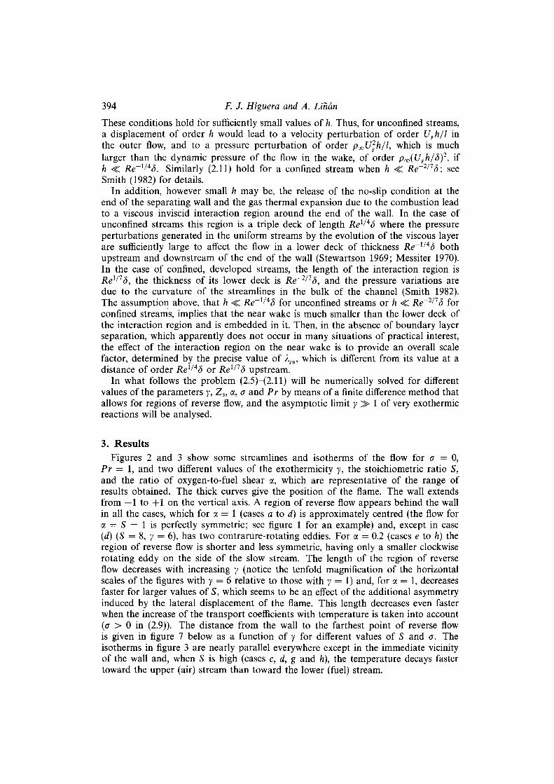
394 F. J. Higuera and A. Liñán
These conditions hold for sufficiently small valúes of h. Thus, for unconfined streams, a displacement of order h would lead to a velocity perturbation of order UFh/l in the outer flow, and to a pressure perturbation of order p^Ujh/l, which is much larger than the dynamic pressure of the flow in the wake, of order p00([/f/i/<5)2, if h < Re~l/4d. Similarly (2.11) hold for a confined stream when h < Re~2/1ó; see Smith (1982) for details.
In addition, however small h may be, the reléase of the no-slip condition at the end of the separating wall and the gas thermal expansión due to the combustión lead to a viscous-inviscid interaction región around the end of the wall. In the case of unconfined streams this región is a triple deck of length Rel^4S where the pressure perturbations generated in the uniform streams by the evolution of the viscous layer are sufficiently large to affect the flow in a lower deck of thickness Re~l/45 both upstream and downstream of the end of the wall (Stewartson 1969; Messiter 1970). In the case of confined, developed streams, the length of the interaction región is Rex,1d, the thickness of its lower deck is Re"111 ó, and the pressure variations are due to the curvature of the streamlines in the bulk of the channel (Smith 1982). The assumption above, that h <C ¿?e~1/4<5 for unconfined streams or h <C Re~2/15 for confined streams, implies that the near wake is much smaller than the lower deck of the interaction región and is embedded in it. Then, in the absence of boundary layer separation, which apparently does not occur in many situations of practical interest, the eflect of the interaction región on the near wake is to provide an overall scale factor, determined by the precise valué of 2.F0, which is different from its valué at a distance of order Rei/Aó or Re1/1d upstream.
In what follows the problem (2.5)™(2.11) will be numerically solved for different valúes of the parameters y, Zs, a, a and Pr by means of a finite difference method that allows for regions of reverse flow, and the asymptotic limit y >• 1 of very exothermic reactions will be analysed.
3. Results Figures 2 and 3 show some streamlines and isotherms of the flow for a = 0,
Pr = 1, and two different valúes of the exothermicity y, the stoichiometric ratio S, and the ratio of oxygen-to-fuel shear a, which are representative of the range of results obtained. The thick curves give the position of the fíame. The wall extends from — 1 to +1 on the vertical axis. A región of reverse flow appears behind the wall in all the cases, which for a = 1 (cases a to d) is approximately centred (the flow for a = S = 1 is perfectly symmetric; see figure 1 for an example) and, except in case (d) (S = 8, y = 6), has two contrarure-rotating eddies. For a = 0.2 (cases e to h) the región of reverse flow is shorter and less symmetric, having only a smaller clockwise rotating eddy on the side of the slow stream. The length of the región of reverse flow decreases with increasing y (notice the tenfold magnification of the horizontal scales of the figures with y = 6 relative to those with y = 1) and, for a = 1, decreases faster for larger valúes of S, which seems to be an eflect of the additional asymmetry induced by the lateral displacement of the fíame. This length decreases even faster when the increase of the transport coefficients with temperature is taken into account (a > 0 in (2.9)). The distance from the wall to the farthest point of reverse flow is given in figure 7 below as a function of y for different valúes of S and a. The isotherms in figure 3 are nearly parallel everywhere except in the immediate vicinity of the wall and, when S is high (cases c, d, g and h), the temperature decays faster toward the upper (air) stream than toward the lower (fuel) stream.

Flow field of an attached flame
2
395
FIGURE 2. Streamlines and flame for a = 0, Pr = 1. Valúes of (a, S, y) are: (a) (1, 2, 1); (b) (1, 2, 6); (c) (1, 8, 1); (d) (1, 8, 6); (e) (0.2, 2, 1); (/) (0.2, 2, 6); (g) (0.2, 8, 1); (h) (0.2, 8, 6).
The flame always starts at one of the edges of the wall in the present approximation, except in the strictly symmetric case mentioned before, and proceeds to the low-velocity wake unless S is very large. For a = 1 the flame always enters one of the eddies, to an extent that depends on S. Thus it reaches the región of negative velocities (toward the wall) for S = 2 (cases a and b), whereas for S = 8 (cases c and d) more oxygen is needed and the flame shifts toward the air stream, sitting in the upper part of the eddy where the velocity is positive. This situation changes for a = 0.2. Then the flame with S = 2 (cases e and / ) starts at the lower (fuel) edge of the wall and never enters the recirculating eddy, having only a short región of negative velocities, whereas with S = 8 (cases g and h) it crosses the eddy through the región of negative velocities. The importance of these differences in connection with the possible extinction of the fíame will be discussed in §5.
The effect of the buoyancy in the región of concern is measured by the Froude number Fr = n^X^/p^gh, if the two streams move vertically and ha ve the same density. This effect may be important when the reaction is sufficiently exothermic. Numerical solutions of the problem with a term (1 — p)/Fr added to the right-hand side of (2.7) (corresponding to upward moving streams) show that the buoyancy shortens the recirculation región, specially on the side of the flow containing the flame, which is the more sensitive. Among other things, this selective shortening may

396 F. J. Higuera and A. Linón 2
FIGURE 3. Isotherms for a = 0, Pr = 1 and the same valúes of (a, S, y) as figure 2. Five equispaced contours between T = 1 and T = Te are shown, with Te = 2 for the left-hand column and Te = 7 for the right-hand column.
change the origin of the recirculating fluid. Thus, in all the cases displayed in figure 2, the fluid recirculating on both sides of the wake comes from the oxygen stream and has already crossed the fíame at some downstream position, whereas on the contrary, for sufficiently small Froude numbers, the fluid recirculating in the oxygen side comes from the fuel stream and crosses the fíame only after reversing the sense of its motion for a second time.
Some pressure distributions are given in figure 4. The pressure gradient is always adverse in the bulk of the recirculation región, pushing the recirculating fluid toward the wall against the viscous shear stresses of the outer streams. This avoids the premature termination of the recirculation región, which is not permitted by the conditions (2.11) of zero displacement until the viscosity has smoothed out the velocity profiles or the gas expansión due to the heat reléase has generated sufficient volume to fill the available space. Further downstream the pressure keeps growing if y is below a certain critical valué yc, dependent on the other parameters, or attains a máximum somewhere behind the recirculation región if y is above yc. It is also worth noticing that the pressure is a decreasing function of x in a very tiny región immediately behind the wall, not clearly visible in figure 4 but that can be seen in figure l(a).
The flow for small valúes of x consists of a recirculation región separated from

Flow field of an attached fíame 397
FIGURE 4. Pressure distribu tions forPr = a = l , S = 2 and 8, and y = (1, 2, 3, 4, 5, 6), from upper to lower curve in each family. Solid: a = 0; dashed: a = 1.
the outer uniform shear flows by two viscous shear layers issuing at the edges of the wall. Transport effects are negligible in the outer flows and in the recirculation región. In this last región the mixture fraction takes a uniform valué Z&, determined by the flow at larger distances downstream from the wall, and the motion of the fluid is induced by the entrainment of the shear layers. In terms of the stream function xp, with pu = dxp/dy and pv = —dxp/dx, the solution in these layers is of the form xp = ± [*2/7i(>?) + xf2(rj) + x4/3/3(>7) + • • •] and Z = Zjfa) + x^Z2{r¡) + x2^Z3(r,) + ••-, where Y\ = (+y — l)/x1/3 and the upper (resp. lower) signs correspond to the upper (lower) layer. The leading terms fi{r\) and Z\{r¡) are the solution of a Goldstein (1930) self-similar problem, consisting of the momentum and mixture fraction conservation equations (the primes meaning difierentiation with respect to r¡)
T"{Tf¡)'} +\f{Tf[)'-\Tf[2 = 0 ,
{T'Z[)' + \PrfxZ[=Q ,
with the boundary conditions
/; = o, zx for -oo
and
(3.1)
(3.2)
(3.3a) fi = OÍTJ2/2 + O(1) , Z\ = 0 for r¡ —• oo
in the upper layer, or
fi = r¡2/2 + o(l) , Zi = 1 for r¡ -»• oo (3.3b)
in the lower layer, and T(Zi) given by (2.5). Since the fluxes in the shear layers are proportional to x2/3, the stream function
in the recirculation región must be of the form xp = x2¡3F(y) + 0(x), and the corresponding velocities lead to a pressure variation p = —Ax4/3 + • •; which is too small to affect the flow in the shear layers to leading order. A pressure decreasing with x is required for conservation of the total head on the streamline of the recirculating
398 F. J. Higuera and A. Liñán
u/xm
JL o v l /3
-4
1 1 1 i — 1 |
„ ' " (a)f f(b) (c) (d)\ (e)\
(a) Áb) (c)^\^. -^Xdf ^ ^ ^ —̂f
-
1 /y\^~^^
i i i i i
O 12
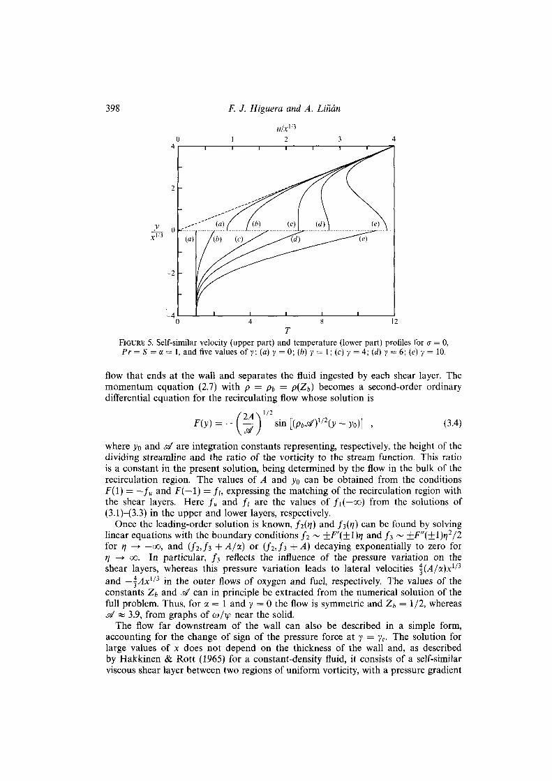
FIGURE 5. Self-similar velocity (upper part) and temperature (lower part) profiles for <r = 0, Pr = S = a = 1, and five valúes of y: (a) y = 0; {b) y = 1; (c) y = 4; (d) y = 6; (é) y = 10.
flow that ends at the wall and separates the fluid ingested by each shear layer. The momentum equation (2.7) with p = pb = p{Zt) becomes a second-order ordinary differential equation for the recirculating flow whose solution is
F(y) = 2A s¿)
1/2
Sin [(p„^y/\y~ y0j¡ (3.4)
where yo and sé are integration constants representing, respectively, the height of the dividing streamline and the ratio of the vorticity to the stream function. This ratio is a constant in the present solution, being determined by the flow in the bulk of the recirculation región. The valúes of A and yo can be obtained from the conditions F(l) = —/„ and F(—1) = //, expressing the matching of the recirculation región with the shear layers. Here fu and /; are the valúes of /i(—oo) from the Solutions of (3.1)—(3.3) in the upper and lower layers, respectively.
Once the leading-order solution is known, f2(n) and f^n) can be found by solving linear equations with the boundary conditions fi ~ +F'{+l)r¡ and fi ~ +F"{+l)r\2/2 for t] —• —oo, and (Ji,fi + A/a) or (/2,/3 + 4̂) decaying exponentially to zero for r¡ —> oo. In particular, / 3 reflects the influence of the pressure variation on the shear layers, whereas this pressure variation leads to lateral velocities |(,4/oc)x1/3
and — |^4x1/3 in the outer flows of oxygen and fuel, respectively. The valúes of the constants Z¡, and sé can in principie be extracted from the numerical solution of the full problem. Thus, for a = 1 and y = 0 the flow is symmetric and Zb = 1/2, whereas sé « 3.9, from graphs of co/ip near the solid.
The flow far downstream of the wall can also be described in a simple form, accounting for the change of sign of the pressure forcé at y = yc. The solution for large valúes of x does not depend on the thickness of the wall and, as described by Hakkinen & Rott (1965) for a constant-density fluid, it consists of a self-similar viscous shear layer between two regions of uniform vorticity, with a pressure gradient
Flow field of an attached fíame 399
such that these regions are not displaced by the presence of the viscous layer. For small valúes of y (in particular for y = 0) an adverse pressure gradient appears to balance the acceleration by viscous forces of the fluid near the solid subsequent to the reléase of the no-slip condition at x = 0, which would displace the outer streams inward. On the other hand, this displacement would be outward for large valúes of y, because the gas thermal expansión offsets the viscous acceleration, and therefore a favourable pressure gradient appears. The solution in the viscous layer is xp = x2/ifHR(riHR), Z = ZHR(r¡HR), p = Cx2l\ with nHR = y /x 1 / 3 and fHR(t]HR) and ZHR(nHR) satisfying (3.1), with a term 2C/3 added to the right-hand side of the first equation, and the boundary conditions
Í'HR =a-nHR+o(i) , ZHR=0
f'HR=-riHR+o(i) , ZHR = \ (3.5)
Sample valúes of yc (at which C = 0) from the solution of (3.1) and (3.5) for a = Pr = 1 and S = (1,2,4,8) are yc = (1.665, 1.617, 1.496, 1.358) when a = 0, and yc = (1.241, 1.214, 1.142, 1.052) when <r = 1. Some velocity and temperature profiles are shown in figure 5. As can be seen, the favourable pressure gradient for y > yc
has a strong effect on the light fluid surrounding the fíame, leading to a local velocity máximum for sufficiently large valúes of y.
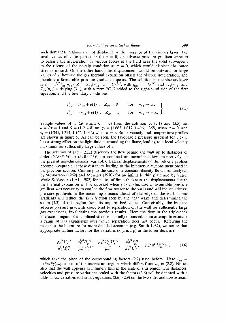
The solution of (2.5)—(2.11) describes the flow behind the wall up to distances of order (5/Re2/1h)i or (5/Rel^4h)3, for confined or unconfined flows respectively, in the present non-dimensional variables. Lateral displacements of the velocity profiles become acceptable at these distances, leading to the interaction regions mentioned in the previous section. Contrary to the case of a constant-density fluid first analysed by Stewartson (1969) and Messiter (1970) for an infinitely thin píate and by Vatsa, Werle & Verdón (1981, 1982) for plates of finite thickness, the displacements due to the thermal expansión will be outward when y > yc (because a favourable pressure gradient was necessary to confine the flow nearer to the wall) and will induce adverse pressure gradients in the oncoming streams ahead of the edge of the wall. These gradients will reduce the skin friction seen by the near wake and determining the scales (2.2) of this región from its unperturbed valué. Conceivably, the induced adverse pressure gradients could lead to separation on the wall for sufficiently large gas expansions, invalidating the previous results. Here the flow in the triple-deck interaction región of unconfined streams is briefly discussed, in an attempt to estímate a range of gas expansions over which separation does not occur. Referring the reader to the literature for more detailed accounts (e.g. Smith 1982), we notice that appropriate scaling factors for the variables (x, y, u, v, p) in the lower deck are
l /4 rr3/2 l /4r r l /2 . . V 4 ; l / 4 r r l / 2 „ 3 /4 ;3/4 P°° UF V™ UF ^°° ÁFL UF ^ ÁFL -l/2..1/2jl/2r7 n M
1/4,5/4 ' 1 /4 ,3/4 ' 1/4 ' 3/4.-.1/2' í'co Meo Af l o
UF> W-V) /*0O 'Voo FOO AFx fJoD POO U F
which take the place of the corresponding factors (2.2) used before. Here ÁFx¡ = —(du/dy)y=o- ahead of the interaction región, which differs from 2F0 in (2.2). Notice also that the wall appears as infinitely thin in the scale of this región. The distances, velocities and pressure variations scaled with the factors (3.6) will be denoted with a tilde. These variables still satisfy equations (2.6)-(2.9) on the two sides and downstream
400 F. J. Higuera and A. Liñán
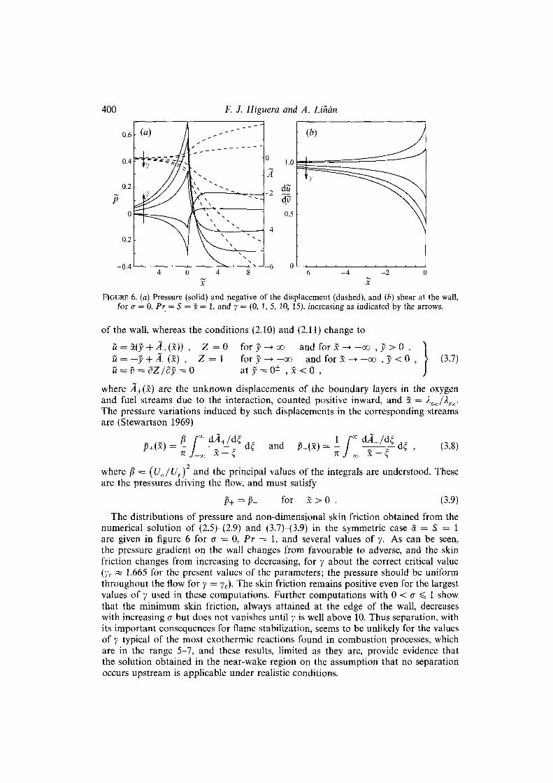
x x FIGURE 6. (a) Pressure (solid) and negative of the displacement (dashed), and {b) shear at the wall,
for <r = 0, Pr• = S = S = 1, and y = (0, 1, 5, 10, 15), increasing as indicated by the arrows.
of the wall, whereas the conditions (2.10) and (2.11) change to
ü = ot(y + Á+(x)) , Z = 0 for y -^ oo and for x —» —oo , y > 0 , "l ü = — y + Á-(x) , Z = 1 for y —> —oo and for x —• —oo , y < 0 , > (3.7) ü = v = dZ/dy = 0 at y = 0± , x < 0 , J
where ^4+(x) are the unknown displacements of the boundary layers in the oxygen and fuel streams due to the interaction, counted positive inward, and S = A0oo/2f.<K. The pressure variations induced by such displacements in the corresponding streams are (Stewartson 1969)
p+(x) = - / ^ + / . s d¿ and ^(X) = - / , x s d¿ , (3.8)
where (i = (U0/UF) and the principal valúes of the integráis are understood. These are the pressures driving the flow, and must satisfy
p+=p- for x > 0 . (3.9)
The distributions of pressure and non-dimensional skin friction obtained from the numerical solution of (2.5)-{2.9) and (3.7)-(3.9) in the symmetric case a = S = 1 are given in figure 6 for a = 0, Pr = 1, and several valúes of y. As can be seen, the pressure gradient on the wall changes from favourable to adverse, and the skin friction changes from increasing to decreasing, for y about the correct critical valué (yc « 1.665 for the present valúes of the parameters; the pressure should be uniform throughout the flow for y = yc). The skin friction remains positive even for the largest valúes of y used in these computations. Further computations with 0 < a < 1 show that the minimum skin friction, always attained at the edge of the wall, decreases with increasing a but does not vanishes until y is well above 10. Thus separation, with its important consequences for fíame stabilization, seems to be unlikely for the valúes of y typical of the most exothermic reactions found in combustión processes, which are in the range 5-7, and these results, limited as they are, provide evidence that the solution obtained in the near-wake región on the assumption that no separation occurs upstream is applicable under realistic conditions.

Flow field of an attached fíame 401
4. Asymptotic limit of very exothermic reactions In this section the structure of the solution of (2.5)—(2.11) in the asymptotic limit
y —> oo, corresponding to very exothermic chemical reactions, is discussed. A limitation to the validity of this asymptotic analysis arises from the outset, because if separation due to the gas expansión occurs in the interaction región before the end of the wall for a certain valué of y, the problem (2.5)—(2.11) is not relevant for y above this valué. The results at the end of the previous section, however, show that boundary layer separation requires very large valúes of y, while the asymptotic results of this section provide a good description of the flow even for modérate valúes of this parameter, in the range of practical interest for gas-phase combustión. This fortúnate circumstance renders the asymptotic results useful despite their formal limitation. Moreover, at least one case exists in which symmetry conditions prevent any outward displacement and no pressure perturbation appears upstream for any y <C Rel/{2a+l\ Such conditions could be realized by setting up a periodic array of alternating streams of fuel and oxygen in adjacent channels formed by an infinite sequence of equal parallel walls like the one considered here, simulating an array of injectors.
Let us begin by describing Goldstein's shear layers for small valúes of x. Here the upper layer is discussed, the other one being analogous, and for convenience a = 1 is set in (3.3a) using the invariance of (3.1) under scale transformations. Since the transition from the cold reactant stream to the hot recirculating fluid occurs across this layer, the whole range of temperatures, from 1 to 0{y), is present. In addition, in the absence of pressure forces the fluid expands freely toward the recirculation región on receiving heat, and the high-temperature región of the shear layer is very thick. As can be easily verified, eqs. (3.1) have solutions with temperature of order unity for r¡ = 0(1) and growing potentially for (—n) > 1, of the form / i ~ b/(—r])l~'"n and T ~ a(-r¡)m, for which
JL = Tf ^ (i _ am) f (4.i)
x l / 3 " (_^)2~-(l+<7)m v '
Here a is a free constant, b = 3[(1 + a)m — l]<f /(2Pr), and
•r-~2]
m(a,Pr)=[k2 + í 2 ^ r - m V 2 - k , (4.2)
with
; = (1 + a)[2 + G- 2Pr(í + 2a)] and k = 2Pr(5 + la) - 5 - 4<r ,
satisfies 1 < m < 2/(1 + a) for 0 ^ a < 1 and any Pr. For these solutions the temperature reaches valúes of order y when (—r¡) becomes of order f/¡ = y1/m 3> 1, and then/! is of order/¡ = l/y1/m-a < 1 and the scaled velocity is Tf[ = 0{\/y2/m-l+a) < 1. Thus the flux and the velocity are very small in the región of high temperature, despite its thickness. Appropriate variables to describe this región are //, = / i / / ¡ , Th = T/y and r¡h = tj/t]¡, and the relationship between the temperature and the mixture fraction in (2.5) becomes
Th = Z/Zs for O ^ Z ^ Z s , ) } (4.3)
T„ = ( l - Z ) / ( 1 - Z s ) for Z S Í S Z < 1 , J
to leading order. Equations (3.1) are left invariant by this rescaling, and must be
402 F. J. Higuera and A. Liñán
solved with the boundary conditions (3.2) and the matching conditions
f"~-(-¿=^ + -~ > Th~a{-t,hr + --- for ( -> f f c ) -0 , (4.4)
where further terms of the expansions, involving two other free constants in addition to a, can be computed from (3.1). In particular, m = 9/5 and b = 6/5 for a = 0, Pr = 1. For c = 1, (4.2) gives m = 1, but the asymptotic expansión for (—r\h) <C 1 contains in this case logarithms of (—r\h). The solution of (3.1), (3.2) and (4.4) depends on a, Pr, Zh, and also on Zs if the shear layer contains the fíame (Z¡, > Zs). This solution is easy to obtain numerically using the two-parameter group of transformations that leave (3.1) invariant, and determines a (which comes out proportional to Z¡, if Zb < Zs)
Another structure of interest arises when one of the reactants is at rest, typically the oxygen, corresponding to a = 0 in the formulation of §2. Then there is no possibility of generating appreciable pressure gradients and the flow consists only of the Navier-Stokes región about the lower edge of the wall followed by a Goldstein's shear layer between the fuel stream and the oxygen mixture. In the limit y —*• oo the asymptotic structure of this layer is similar to the one just discussed if the oxygen temperature is high, with this reactant playing then the role of the recirculating fluid. However, if both reactants are cold, the structure of the shear layer near the oxygen side is different and depends strongly on the Prandtl number. With CT = 0 and the variables scaled as before, the solution for Pr < 1 is of the form fh ~ /oo + bexp (-lfM-Pr)r¡h) and Th ~ aexp (-\faoPrr\h), with /«, > 0, for r¡i¡ —>• oo, whereas for Pr > 1 the high temperature región extends only to a finite 1h = »?/!„, the solution being of the form fh ~ (3/2)(m' — l)/[Pr(t]hu — r¡h)} and Th ~ a(r\K - r¡h)
m', with rrí = 3(4Pr - l)/[2m(Pr - 1)] > 3, for (r¡K - m) < 1. The differences arise because the effect of the heat conduction extends farther than that of the viscosity when Pr < 1, preheating the oxygen mixture and decreasing its density before it is ingested by the shear layer, which results in a finite ingestión rate from this side of the layer. On the other hand, for Pr > 1 the viscosity reaches farther than the heat conduction and the ingested fluid is denser, resulting in an infinite ingestión rate with the scales of the high-temperature región.
Corning back to the case a > 0, let us consider the recirculating flow between the two shear layers. The ingestión of the layers induces velocities of order yi+°-i/mx2/3, and the pressure variations are of order yi+2<r-2/mx4/3 for sufficiently small x. As was mentioned before, these pressure variations are too weak to affect the cold streams of the reactants, which therefore do not suffer any lateral displacement, confining the growth of the shear layers to the space behind the wall. In these conditions, the high-temperature regions of the two shear layers interfere, and Goldstein's self-similar solution ceases to be applicable, at a distance of order xj, = rj~3 = y~3/m < 1 behind the wall, obtained by writing \y — 1| = 1 in the expression for r¡. This x¡, is the characteristic length of the recirculation región, where the velocity of the fluid is of order u¡, = y1+<r-3/m and the pressure variations are of order pb = •y1+2ff-6/m. Since such pressure variations are still too small to affect the flow in the cold regions of the shear layers when a < 1, that flow remains self-similar over the recirculation región and beyond. For example, for a = 0 and Pr = 1, x¡, = }>~5/3, u¡, = y~2/i and pb = y~7/\ while the velocity and the dynamic pressure in the cold parts of the shear layers are much larger, of orders y~5/9 and y~10/9. For a = 1, xb = y~3 and the velocities in the hot and cold fluids are both of order y~l. Logarithmic plots of the distance from the wall to the farthest point of negative velocity as a function of y, obtained from the

Flow field of an attached fíame 403
10 ' -
io-2 -
10"
i i i ^ ^ v
^ **-. O 1 V
S=2 - 4 - -
\ •-.. " - - - ^ * k / " ~ - . 5 = 4 . Q . . . ~ X "•-••••<-g!***^ S=8 -X ~ :
•
•
^¿ft^~^
, '™ ( a ) ^ X
\ * vv* » v\> * ^vt «> » T^\> ; ~
• •
v*iV * * vs>
•
X; x \
10
FIGURE 7. Distance to the farthest point with negative velocity as a function of Te = 1 + y for Pr = a = 1 and (a) a = 0, (b) a = 1. The longer dashed lines have the slopes (a) —5/3, (b) —3 predicted by the asymptotic theory.
numerical solution of (2.5)—(2.11), are given in figure 7 for these two cases, showing a rapid approach to the asymptotic behaviour as y increases.
For x > Xb the región of high temperature is confined by non-compliant streams of heavy fluids and cannot keep on growing as in the freely expanding shear layers for x <C Xb. Since heat conduction from the flame continually heats up more fluid, its motion in the strip |y| < 1 requires a favourable pressure gradient, whose origin is in minute deflections of the outer streams, to be discussed later. In the strip of high temperature, the balance of convection, 0(u2/yx), viscous forcé, 0(y"u), and pressure forcé, gives u = 0{yl+ax) and Ap = 0(y1+2ax2), and, under the action of the gradient of this pressure, the velocity profile of the light fluid rapidly changes from the wake-like shape prevailing for x < xj to the jet-like shape depicted in figure 5. Eventually the pressure variations become of order unity, for x of order xc = l/yff+1/2, and the strip of light fluid begins to thicken, displacing the cold streams sideways.
The solution in the high-temperature región for x¡, <C x < xc is of the form
xp = yaxG(y) Z(y) p = Vo-yWax1B/2 (4.5)
where G(y) and Z(y) satisfy the equations (primes meaning now derivatives with respect to y)
T°h (ThG')'l + G (ThG')' - ThG'2 = -B and (T¿Z')' + PrGZ' = 0 , (4.6)

404 F. J. Higuera and A. Liñán
wíth the scaled temperature given by (4.3), and the boundary conditions
TG' = 0 , Z = 0 at y = 1 , 1 \ (4-7)
TG' = 0 , Z = 1 at y = - 1 . J The conditions of zero velocity at the boundaries express the matching of this región to others where much heavier fluid under the same pressure gradient moves much slower. For sufficiently small valúes of x the strip of light fluid is limited by warm strata of Goldstein's shear layer, where the velocity is given by (4.1) and p = [a(—r¡)m]~x. Using these quantities, the condition pu2 = O(Ap) yields (-r¡) = o[xy3(1+2a)/4]-4/i(4-(i+2c!)m> for the inner boundary of the región of the shear layer not affected by the pressure gradient at a given x. This (—n) becomes of order unity for x of order y-3<1+2ff)/45 and no remnant of Goldstein's self-similar flow is left for larger valúes of x.
It turns out that (4.6) and (4.7) determine not only G(y) and Z(y) but also the unknown constant B in the expression for the pressure. This is because any solution of (4.6) satisfying the four boundary conditions (4.7) also satisfies the two additional conditions
í TkG'2dy = 2B and / GZ'dy = 0 (4.8)
expressing the conservation of the fluxes of momentum plus pressure and mixture fraction in the strip. Conditions (4.8) are obtained by integrating equations (4.6) across the strip and using the asymptotic expansions of the solution near the boundaries. Near the upper boundary, ( l - y ) < l , these expansions are of the form
A D0/(l+2<7) G= (1-^)/(^)+-"' Th = c0B^\l-yf^ + - (4.9a)
if a < 1/2, where c0 and do are known functions of a and Pr, or
G=^r+d(l- y)WW» + ^ f * (1 - yf-* + aPr 2a — 1 aPr — 1 ca+l
Th = c(l-y)1" + ---
} (4.9¿)
if a > 1/2, where c and d are free constants, and similar expressions hold for (l+y) <C 1. Because of (4.9a), the diffusion fluxes of momentum and mixture fraction and the convective flux of momentum are zero across the lateral boundaries.
Numerical integration of (4.6) was carried out with a shooting method using the previous expansions (with two more terms of the expansions (4.9a) providing two free constants, much as in (4.4) above). Some results for a = 0 and Pr = 1 are B = (56.69, 61.11, 74.35, 96.25) for S = (1, 2, 4, 8).
As was already mentioned in the paragraph above (4.5), the pressure variations become of order unity and the strip of hot fluid begins to open up when x becomes of order xc = l/ya+l/2. By then (4.5) gives velocities of order yl/2 and the flow in the strip is described by equations (2.5)-(2.9) rewritten in terms of the scaled variables X = x/xc, Uh = u/y1/2, Vh = v/y1+a, Tu = T/y and ph = yp, of order unity here, with the boundary conditions
(4-10) Uh = Z = 0 at y = Ó+(X)
Uh = Z — 1 = 0 at y = s~(x)

Flow field of an attached flame 405
and
uh -> XG'(y) , Z -* Z(y) given by (4.6) and (4.7), for X -* 0 . (4.11)
Here S+ are the unknown upper and lower boundaries of the strip. The solution near these boundaries is still of the form (4.9a), with (1 — y) replaced by |<5± — y\ and the coefficients of the expansions depending on X. As before, the fluxes of momentum and mixture fraction are conserved, leading to
^ J + phu2
h áy + (<5+ - SJ)^ = 0 and ~ j + phuhZ áy = 0 , (4.12)
which would permit solving the problem if S+(X) were known. Two further relations between Ó+(X) and p(X), closing the problem, arise from the analysis of the cold streams. There the effect of the viscosity is negligible and the vorticity remains uniform
1 II in each stream, except in two thin layers of thickness 0(xc ) around the strip that need not be considered in detail. The velocity profiles are linear and the conditions (2.11) of zero displacement of these profiles are satisfied at infinity only if they are satisfied everywhere else; i.e. the outward displacement of each streamline in the lower stream must equal the increase of the velocity on it, and the outward displacement of each streamline in the upper stream must equal a - 1 times the increase of outward velocity on it. In addition, because of the low density, the mass flux across the strip is only of order y~l/1, much smaller than the fluxes of the cold streams over regions of comparable thickness, in such a way that the boundaries of the strip appear as impermeable from the point of view of the outer streams. Bernoulli's theorem on the streamlines bounding the región of high temperature above and below then yields
p + ¿a2(<5+-l)2 = p+i(<5_ + l)2 = 0 , (4.13)
which are the two relations sought for. For large valúes of X the upstream thickness of the strip becomes irrelevant and
the flow takes on a self-similar form corresponding to the asymptotic limit of the Hakkinen-Rott solution for y —• oo, in which f = X2/3fHR(r¡HR), Z = ZHR{r¡HR) and p = CX2/3 (W being the scaled stream function and C < 0), with r¡HR = y/Xl/i, d+ = A+X1^ and aá+ = -A- = (-2C)1/2. The functions fHR(nHR) and ZHR(r,HR) satisfy (3.1), with the term 2C/3 added to the right-hand side of the first of these equations, and the boundary conditions
T»C =ZHR=0 at r,HR = A+ and ThfHR = ZHR - 1 = 0 at r,HR = zL . (4.14)
Near the upper and lower boundaries the stream function and the temperature are of the forms (4.9), with — C taking the place of B and extra factors of 3/2 multiplying and dividing respectively the first and third terms of the first equation (4.9b). The solution also determines C. For example C « —2.365 for the symmetric case S = a. = 1 with a = 0 and Pr = 1.
To cióse this section the asymptotic limit S —> oo, which is of interest because large valúes of S are frequently found in practical cases, is briefly discussed. Unfortunately the asymptotic expansión of the solution in this limit is in powers of the logarithm of S, being therefore of limited applicability, so only the main features of this solution will be mentioned here. In the (upper) Goldstein layer for x < x ¡ , the thickness of the high-temperature región becomes very large below the flame, O [(ln S)1/3] for (7 = 0 and Pr = 1, and the distance from the flame to the upper boundary of the layer becomes very small, O [(lnS)~2/3]. The scaled mass flux is f'h = O [(lnS)4/3]

406 F. J. Higuera and A. Liñán
above the flame and much smaller, O [(lnS)1/3], underneath, and, since f'h must be continuous, the velocity at the flame is effectively zero from the point of view of the región above it. This situation changes somewhat farther downstream, owing to the favourable pressure gradient. Thus, in the Hakkinen-Rott solution, the asymptotic analysis yields C « — ( | lnS) , whereas the thickness of the hot región is still O [(lnS)1/3] below the flame and O [(lnS)~1/6] above the flame, and f'h = 0 [(InS)4/3] at both sides of the flame, which appears as a surface of zero shear from the point of view of the región above it.
5. Flame attachment 5.1. Effect of the wall thickness
The analysis of the previous sections was aimed at describing the flow field of an existing flame, and was carried out on the assumption that the chemical reaction is sufficiently fast for the flame to remain attached under any condition. The results, however, shed some light on the issue of conditions for flame attachment and the different types of flame lift-off, and will be discussed here in that connection.
Notice first that the local burning rate at each point of the flame is given by the diflusion fluxes of fuel and oxygen, which arrive in stoichiometric proportions from opposite sides of the flame. In a real flame, however, finite-rate chemistry effects, not accounted for in the present analysis, impose an upper limit on the admissible fluxes, because local extinction occurs when the diffusion time becomes shorter than the chemical time tch = pF/wc, where wc is the characteristic valué of w in the right-hand side of (2.1) evaluated at the adiabatic flame temperature (Liñán 1974).
Both the reciprocal of the diflusion time and the burning rate are conveniently measured by the local valué of the scalar dissipatíon x ~ (P-/pPr)(SZ /dy)2 at the flame. Maps of the scalar dissipation % with the flame superimposed are given in figure 8 for the same sets of parameter valúes used in figures 2 and 3. In the present non-dimensional variables x tends to infinity at the edges of the wall (see §5.2), but away from these points the scalar dissipation on the flame, and therefore the possibility of local extinction, depends strongly on the valúes of the parameters. For a = 1, the flame with S = 2, (a) and (b), manages to avoid the región of higher dissipation until very near the wall, whereas the flame with S = 8, (c) and (d), lies in the middle of that región (which anyway is shorter than for S = 2). For a = 0.2, the flame with S = 2, (e) and (/), starts at the lower (fuel) edge, where the dissipation is higher, but now lies on top of the ridge of máximum dissipation, and the flame with S = 8, (g) and (h), starts at the upper (air) edge and immediately bends downward.
Upon inspection of figures 2 and 8 two possibilities present themselves. In cases like (a) and (b) (oc = 1, S = 2) or (g) and (h) (a = 0.2, S = 8), and to
a lesser extent also in cases (e) and (/) (a = 0.2, S = 2), the velocity of the flow on the flame is directed toward the wall when the flame enters the región of highest dissipation. This región can then be considered as the flame tail rather than the flame head, in the sense that if the flame extinguishes here it can still survive downstream, where x is smaller. Of course the flow between the extinction point and the wall will be different from the one described before, because the temperature on the surface Z — Zs will be lower than the adiabatic flame temperature and the reactants will diffuse into each other. These changes, however, need not have a strong effect on the flame downstream if the distance from the extinction point to the wall is small compared with the size of the recirculation región (as seems to be often the case,

Flow field of an attached flame
2r
407
FIGURE 8. Scalar dissipation and flame for the cases of figure 2. Contour spacing is 0.03 in (a) and (c), 0.06 in (e) and (g), and 0.2 in (b), (d), (/) and (h).
judging by the limited extent of the región of high dissipation), because the warm fluid still recirculates and the oxygen-fuel mixture, which will burn anyway on reaching the flame again, occupies only a small región. When, by changing' the parameters, the tail of the flame reaches the rear or the lateral boundaries of the región of negative velocity, lift-off would occur in the fashion of the Type III instability of Takahashi & Schmoll (1990).
On the other hand, in cases like (c) and (d) (a = 1, S = 8) the flow is directed away from the wall over the región of the flame more prone to extinction. Now, if the nose of the flame (a triple fíame; see Liñán 1994) cannot attach in a short región by the edge of the wall whose size will be estimated in the following subsection, it will not be able to exist downstream (though a diffusion flame could), and combustión will not occur at all in the vicinity of the injector. It should be noted here that the mere recirculation of hot fluid does not help in anchoring the flame front when the Lewis numbers are equal to unity, because the increase of temperature is associated with a decrease of the reactant concentrations, in such a way that the enthalpy (thermal plus formation) of the recirculating fluid is the same as in the cold streams. It should also be noted that, even under these adverse conditions, the región of low velocity around the rear stagnation point still provides a favourable environment for a steady triple flame to exist, with the two reactants and the combustión products coexisting all

408 F. J. Higuera and A. Liñán
over the bubble. This possibility, however, falls outside the framework of the present analysis.
Quite independently of these results, it may also be remarked that inflexional velocity profiles are a characteristic feature of very exothermic reactions. Though no stability analysis will be carried out here, it seems a reasonable conjecture that such profiles may become unstable and lead to high turbulent strain rates that could extinguish the fíame at some distance downstream of the recirculation región. This extinction would be in line with the observations of split flames by Vranos et al. (1968) and by others, and would occur in a región whose width bears no relation to the width of the fuel jet.
5.2. Región of fíame attachment The highest valúes of x, oí order tjl = XF¡¡ in dimensional variables, occur in the small Navier-Stokes regions of size SNS = Re~i/2d = (fi^/'p^X^)112 around the edges of the wall, where the velocity of the fluid is of order uNS = (/4o¿r0/p<x>)1/2 and the heat conduction toward the solid against the stream is important.
These small regions, which will not be analysed here, are known to play a key role in the attachment of flames with finite-rate chemistry when one of the reactants is at rest or when the thickness of the wall is comparable to SNS. Then, a rough criterion of fíame attachment (Lewis & von Elbe 1961) is that the diffusion time t¿ should be of the order of the chemical time tch or larger or, equivalently, that the propagation velocity of the corresponding stoichiometric premixed fíame, O(fiao/pootch)l/2, be of the order of uNS or larger. If t¡¡ is shorter than tch the chemical reaction has no time to occur in the aforesaid regions, and, as mentioned in the previous subsection, a steady triple fíame cannot exist in Goldstein's shear layer immediately behind either, because the velocity of the flow here is larger than the velocity of propagation of the fíame. In these conditions the fíame lifts off the injector rim or is blown out completely. On the other hand, the triple fíame always finds an equilibrium position in the Navier-Stokes región if t¿ is larger than tCh, because, owing to the heat losses toward the solid, the excess of enthalpy (H; cf. (2.3)) is negative in this región and the temperature of the front gets smaller than the adiabatic fíame temperature, increasing drastically the chemical time. Then the fíame front provides a continuous ignition source for the diffusion fíame downstream.
The mechanism of fíame stabilization seems to be somewhat different when both fluids move and the thickness of the separating wall is much larger than SNS, and the Navier-Stokes regions then play a less prominent role. This can be seen by analysing the flow about the edge. At a distance r >• dNS from the edge the flux carried by Goldstein's shear layer is of order pcouNSóNS(r/dNS)
211 and the entrainment of this layer leads to an effectively inviscid flow below, with velocity O ^ í r / á ^ ) - 1 / 3 ] , and to a boundary layer of thickness <5NS(r/<SNS)
2/3 on the vertical side of the wall. With a fíame present, the fluid entering this boundary layer comes from regions of high temperature downstream and loses heat toward the wall, which results in a deficiency of enthalpy. Further, most of this fluid leaves the boundary layer before reaching the Navier-Stokes región (the flux in the boundary layer is of order po0uNSSNS(r/dNS)
1/i, decreasing with r) and is ingested by the shear layer after crossing the inviscid región in between. On a wall of thickness h ( > óNS), the máximum thickness attained by this boundary layer is of order dNS(h/SNS)
2/3 and the corresponding flux, 0[poo"„s¿ws(Ji/<5Ws)1/3L is ingested by the shear layer at a distance of order ¿NS(/j/(5NS)
1/2 from the solid. This defines the length of the attachment región, over which the enthalpy of the flow in the shear layer, as well as its velocity, is an increasing function of the distance from

Flow field of an attached flame 409
the wall. Notice, however, that for a triple fíame to exist here its propagation velocity has to match that of the flow, which is faster than in the Navier-Stokes región.
The solutions in the different regions mentioned above can be easily obtained as follows. First, in the inviscid recirculation región Xi > 0, \y\ ^ 1, with the streamwise
distance now scaled with h, the stream function \pi (scaled with [/lf0/i2/i^/poo] )
obeys V2i£>i = —Pb-^^i with the boundary conditions ip1 = 0 at x\ = 0 ; dtpi/dxi = ±j(fu,i/x\/3) at y = ± 1 ; and \px -> x2/3F(y) for xi - • oo, where pb, sé, /„, /;, and F(y) are defined in §3. The solution of this problem determines the slip velocity (l/pb)(d\pi/dxi)Xl=o driving the flow in the boundary layer on the rim of the injector. Second, knowing this velocity and the temperature Tb of the fluid outside the boundary layer, and assuming that the temperature of the solid is T = 1, the velocity and temperature in the boundary layer can be immediately computed for yo < y < 1 and for — 1 < y < y0. This solution determines the temperature distributions, Tuj(xp2) say, for y —• +1, where xp2 is the stream function in the boundary layer (scaled with P°O"NS<5NS(/I/<5ÍVS)1/3)- Third, the flow in the upper shear layer upstream of the flame front (the lower shear layer is similar) obeys the boundary layer equations (2.6)-(2.9) without pressure gradient, plus an equation similar to (2.8) for the enthalpy excess H defined in (2.3), subject to the boundary conditions
d\p2
and
= a(y2 + 0), Z = 0, H = 0 for y2 -* oo oyi
dWl - 0, Z=Zb, H = Tu(xp2) - Tb for y2 - -oo dy2
where y2 = (y — h)/ [¿NS(h/SNS)1/6] is of order unity in the shear layer for x2 =
x/ [5NS(h/dNS)1/2] = 0(1). The solution of this problem determines the distributions
of velocity, Z, and H ahead of the flame, where the mixture fractions of the reactants and the temperature are Y0 = (Zb — Z)/Zb, YF = {Z/Zb)(Zb — Zs)/(1 — Zs), and T = 1 + H — y(Yr + Y0 — 1). Finally, with these data, a local analysis along the lines of Liñán (1994) would determine if a triple flame matching the velocity of the fluid can exist at some section of the shear layer.
By way of example, this program was carried out for a = 1 and y —• 0, in which limit /„ = // « —1.258, the recirculating flow and the boundary layers are symmetric, and the velocity in the shear layers is self-similar, not being affected by the presence of the flame. If the flame front were to sit at a certain position in one of the shear layers, the concentration of the rich reactant on the flame and the fíame temperature, obtained from (2.3) with the condition that the concentration of the lean reactant be zero, would be given by the first relations in (2.5) and
l + y Z / Z s + i í for 0 ^ Z ^ Z s
Tf = < i + y ^ Y + H for Z S < Z < 1 ,
respectively. The scaled temperature rise (7/ — \)/{Te — 1) as a function of {x2,y2) is shown in
figure 9 for S = 4. In this particular case the máximum temperature in each section is attained where Z = Zs. The velocity of the nose of the flame front, equal to the burn-ing rate of the corresponding planar premixed flame, is a rapidly increasing function of Tf and depends more weakly on the concentration of the rich reactant on the fíame

410 F. J. Higuera and A. Liñán
2.0 i
FIGURE 9. Increment of temperature at the fíame in the región of enthalpy defect for Pr = a = 1, S = 4, and y -* 0. Contours plotted are (Tf - l)/(Te - 1) = 0.7, 0.75, 0.8, 0.85, and 0.9, increasing from left to right. Dashed: contour Z = Zs.
(see, e.g., Williams 1985), so the point in the shear layer where this velocity matches the velocity of the fluid can be easily determined for any given burning rate law.
Two other factors that might facilitate the attachment of the fíame can be men-tioned. Firstly, the heat transferred by the recirculating fluid to the solid may be recovered by the oncoming streams of reactants, at a large distance from the end of the wall if its conductivity is high, in such a way that the enthalpy is merely redistributed and the enthalpy defect of the flow entering the shear layer from the recirculation región can be balanced by the enthalpy excess of the flow entering from the reactant stream. Secondly, the velocity of the flow in the región of the shear layer containing the fíame may be appreciable lowered by the effect of the gas expansión for sufficiently large valúes of y (cf. §4).
R E F E R E N C E S
GAYDON, A. G. & WOLFHARD, H. G. 1953 Flames-Their Structure, Radiation, and Temperature, p. 39. Chapman & Hall.
GOLDSTEIN, S. 1930 Concerning some solutions of the boundary-layer equations in hydrodynamics. Proc. Camb. Phil. Soc. 26, 1-30.
HAKKINEN, R. J. & ROTT, N. 1965 Similarity solutions for merging shear flows II. AIAA J. 3, 1553-1554.
KAWAMURA, T. & ASATO, K. 1975 The structure of the stabilizing región of a laminar fuel jet fíame. Proc. 2nd European Symp. on Combustión, pp. 611-616. The Combustión Institute, Pittsburgh.
KAWAMURA, T, ASATO, K. & MAZARÍ, T. 1980 Structure analysis of the stabilizing región of plañe, laminar fuel-jet flames. Combust. Sci. Tech. 22, 211-216.
LEWIS, B. & ELBE, G. VON 1961 Combustión, Fiames and Explosions of Gases, 3rd. edn., pp. 233-236. Academic Press.
LIÑÁN, A. 1974 The asymptotic structure of laminar diífusion flames for large activation energies. Astro. Acta 1, 1007-1031.
Flow field of an attached flame 411
LIÑÁN, A. 1994 Ignition and flame spread in laminar mixing layers. In Combustión in High Speed Flows (ed. J. Buckmaster et ai), pp. 461-476. Kluwer.
MESSITER, A. F. 1970 Boundary layer flow near the trailing edge of a flat píate. SIAM J. Appl. Maths 18, 241-257.
ROBSON, K. & WILSON, M. J. G. 1969 The stability of laminar diffusion flames of methane. Combust. Flame 13, 626-634.
SMITH, F. T. 1982 On the high Reynolds number theory of laminar flows. IMA J. Appl. Maths 28, 207-281.
STEWARTSON, K. 1969 On the flow near the trailing edge of a flat píate II. Mathematika 16, 106-121. TAKAHASHI, R, MIZOMOTO, M., IKAI, S. & FUTAKI, N. 1984 Lifting mechanism of free jet diffusion
flames. 20th Symp. on Combustión, pp. 295-302. The Combustión Institute. TAKAHASHI, F. & SCHMOLL, W. J. 1990 Lifting criteria of jet diffusion flames. 23rd Symp. on
Combustión, pp. 677-683. The Combustión Institute. VATSA, V. N., WERLE, M. J. & VERDÓN, J. M. 1981 Analysis of laminar and turbulent blunt
trailing-edge flows. Report R81-914986-5. United Tech. Res. Center, East Hartford, Conn. VATSA, V. N., WERLE, M. J. & VERDÓN, J. M. 1982 Viscid-inviscid interaction at laminar and
turbulent symmetric trailing edges. AIAA Paper 82-0165. VRANOS, A., TABACK, E. D. & SHIPMAN, C. W 1968 An experimental study of the stability of
hydrogen-air diffusion flames. Combust. Flame 12, 253-260. WILLIAMS, F. A. 1985 Combustión Theory, 2nd edn., chapter 3. Benjamin/Cummings. YOON, Y, DONBAR, J. M. & DRISCOLL, J. F 1994 Blowout stability limits of a hydrogen jet flame in
a supersonic, heated, coflowing air stream. Combust. Sci. Tech. 97, 137-156.