Embed Size (px)
Citation preview
ww.sciencedirect.com
i n t e r n a t i o n a l j o u r n a l o f h y d r o g e n en e r g y 3 8 ( 2 0 1 3 ) 4 0 8 9e4 0 9 8
Available online at w
journal homepage: www.elsevier .com/locate/he
Effect of surface wettability of polymer composite bipolarplates on polymer electrolyte membrane fuel cellperformances
Fatma Gul Boyaci San*, Isil Isik-Gulsac
Energy Institute, TUB_ITAK Marmara Research Center, P.O. Box 21, 41470 Gebze, Kocaeli, Turkey
a r t i c l e i n f o
Article history:
Received 22 November 2012
Received in revised form
16 January 2013
Accepted 19 January 2013
Available online 19 February 2013
Keywords:
Bipolar plate
Surface wettability
Fuel cell
Polymer composite
* Corresponding author. Tel.: þ90 262 677 27E-mail addresses: fatmagul.boyaci@tubita
0360-3199/$ e see front matter Copyright ªhttp://dx.doi.org/10.1016/j.ijhydene.2013.01.1
a b s t r a c t
The effects of fluoropolymer based additive at different additive/binder and additive/filler
ratios on surface wettability, conductivity andmechanical properties of polymer composite
bipolar plates are investigated in this study. Fuel cell performance tests are performed at
different feed flow rates by using composite bipolar plates containing organic based hy-
drophobic and inorganic based hydrophilic additives to investigate the effect of surface
wettability properties on polymer electrolyte membrane fuel cell (PEMFC) performance.
The conductivity of the composite materials decreases with the increase in additive/filler
ratios, due to a decrease in the amount of conductive filler in the composite structure,
whereas conductivity increases with the increase in additive/binder ratios due to
a decrease in the amount of nonconductive binder. The surface hydrophobicity gets
stronger with increasing fluoropolymer/filler and fluoropolymer/binder ratio amounts,
related to the hydrophobic properties of both filler and fluoropolymer. In all feed flow rates,
at low current densities, the single cells exhibit almost the same performance. At inter-
mediate and high current densities, polymer composite without any additives shows
higher performance than the bipolar plates containing organic or inorganic based addi-
tives. Current and power densities show maxima at the bipolar plate contact angle of 80�.
Copyright ª 2013, Hydrogen Energy Publications, LLC. Published by Elsevier Ltd. All rights
reserved.
1. Introduction The fuel cell stack is mainly composed of bipolar plates,
Polymer electrolyte membrane fuel cells (PEMFCs) represent
one of the most promising power production technologies in
the near future; because of their zero emissions, low noise and
operating temperatures, relatively quick startup, rapid
response to varying loads, high efficiencies and power den-
sities. They find application in many areas, including power
supplies in cellular telephones, laptop computers and port-
able entertainment equipments, automobiles, residential
power, and military communication installations [1e5].
03; fax: þ90 262 642 35 54k.gov.tr, [email protected], Hydrogen Energy P35
end plates and membrane electrode assembly (MEA). MEAs
have fuel electrode (anode) and oxidant electrode (cathode)
separated by an ion conducting electrolyte/membrane.
Hydrogen passes over one electrode and oxygen over the
other, generating electricity, water and heat. The bipolar plate,
which is one of the key components of PEMFC, contacts with
the surface of the cathode and the anode of the next cell [2e4].
A simplified structure of a PEMFC stack is given in Fig. 1.
The bipolar plate has five main functions: distribution of
gases homogeneously over anode and cathode, separation of
.m (F.G. Boyaci San).ublications, LLC. Published by Elsevier Ltd. All rights reserved.
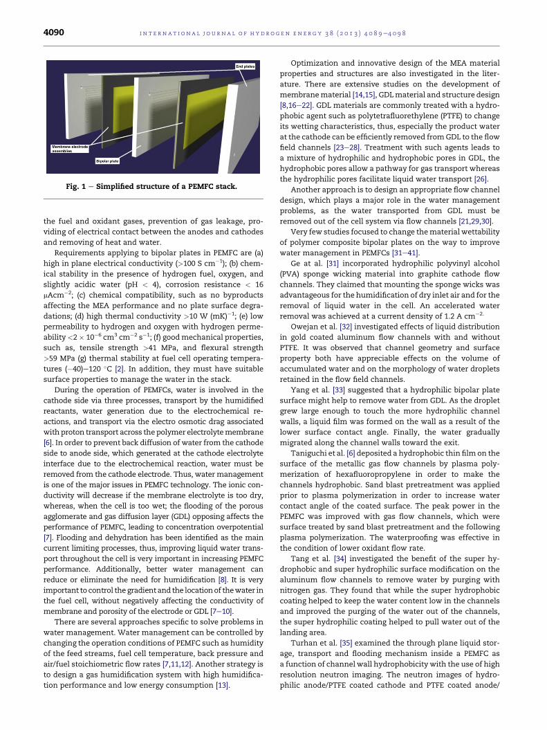
Fig. 1 e Simplified structure of a PEMFC stack.
i n t e rn a t i o n a l j o u r n a l o f h y d r o g e n en e r g y 3 8 ( 2 0 1 3 ) 4 0 8 9e4 0 9 84090
the fuel and oxidant gases, prevention of gas leakage, pro-
viding of electrical contact between the anodes and cathodes
and removing of heat and water.
Requirements applying to bipolar plates in PEMFC are (a)
high in plane electrical conductivity (>100 S cm�1); (b) chem-
ical stability in the presence of hydrogen fuel, oxygen, and
slightly acidic water (pH < 4), corrosion resistance < 16
mAcm�2; (c) chemical compatibility, such as no byproducts
affecting the MEA performance and no plate surface degra-
dations; (d) high thermal conductivity >10 W (mK)�1; (e) low
permeability to hydrogen and oxygen with hydrogen perme-
ability<2� 10�6 cm3 cm�2 s�1; (f) goodmechanical properties,
such as, tensile strength >41 MPa, and flexural strength
>59 MPa (g) thermal stability at fuel cell operating tempera-
tures (�40)e120 �C [2]. In addition, they must have suitable
surface properties to manage the water in the stack.
During the operation of PEMFCs, water is involved in the
cathode side via three processes, transport by the humidified
reactants, water generation due to the electrochemical re-
actions, and transport via the electro osmotic drag associated
with proton transport across thepolymer electrolytemembrane
[6]. In order to prevent back diffusion of water from the cathode
side to anode side, which generated at the cathode electrolyte
interface due to the electrochemical reaction, water must be
removed from the cathode electrode. Thus, water management
is one of the major issues in PEMFC technology. The ionic con-
ductivity will decrease if the membrane electrolyte is too dry,
whereas, when the cell is too wet; the flooding of the porous
agglomerate and gas diffusion layer (GDL) opposing affects the
performance of PEMFC, leading to concentration overpotential
[7]. Flooding and dehydration has been identified as the main
current limiting processes, thus, improving liquid water trans-
port throughout the cell is very important in increasing PEMFC
performance. Additionally, better water management can
reduce or eliminate the need for humidification [8]. It is very
important to control the gradientand the locationof thewater in
the fuel cell, without negatively affecting the conductivity of
membrane and porosity of the electrode or GDL [7e10].
There are several approaches specific to solve problems in
water management. Water management can be controlled by
changing the operation conditions of PEMFC such as humidity
of the feed streams, fuel cell temperature, back pressure and
air/fuel stoichiometric flow rates [7,11,12]. Another strategy is
to design a gas humidification system with high humidifica-
tion performance and low energy consumption [13].
Optimization and innovative design of the MEA material
properties and structures are also investigated in the liter-
ature. There are extensive studies on the development of
membranematerial [14,15], GDLmaterial and structure design
[8,16e22]. GDL materials are commonly treated with a hydro-
phobic agent such as polytetrafluorethylene (PTFE) to change
its wetting characteristics, thus, especially the product water
at the cathode can be efficiently removed fromGDL to the flow
field channels [23e28]. Treatment with such agents leads to
a mixture of hydrophilic and hydrophobic pores in GDL, the
hydrophobic pores allow a pathway for gas transport whereas
the hydrophilic pores facilitate liquid water transport [26].
Another approach is to design an appropriate flow channel
design, which plays a major role in the water management
problems, as the water transported from GDL must be
removed out of the cell system via flow channels [21,29,30].
Very few studies focused to change thematerial wettability
of polymer composite bipolar plates on the way to improve
water management in PEMFCs [31e41].
Ge at al. [31] incorporated hydrophilic polyvinyl alcohol
(PVA) sponge wicking material into graphite cathode flow
channels. They claimed that mounting the sponge wicks was
advantageous for the humidification of dry inlet air and for the
removal of liquid water in the cell. An accelerated water
removal was achieved at a current density of 1.2 A cm�2.
Owejan et al. [32] investigated effects of liquid distribution
in gold coated aluminum flow channels with and without
PTFE. It was observed that channel geometry and surface
property both have appreciable effects on the volume of
accumulated water and on the morphology of water droplets
retained in the flow field channels.
Yang et al. [33] suggested that a hydrophilic bipolar plate
surface might help to remove water from GDL. As the droplet
grew large enough to touch the more hydrophilic channel
walls, a liquid film was formed on the wall as a result of the
lower surface contact angle. Finally, the water gradually
migrated along the channel walls toward the exit.
Taniguchi et al. [6] deposited a hydrophobic thin filmon the
surface of the metallic gas flow channels by plasma poly-
merization of hexafluoropropylene in order to make the
channels hydrophobic. Sand blast pretreatment was applied
prior to plasma polymerization in order to increase water
contact angle of the coated surface. The peak power in the
PEMFC was improved with gas flow channels, which were
surface treated by sand blast pretreatment and the following
plasma polymerization. The waterproofing was effective in
the condition of lower oxidant flow rate.
Tang et al. [34] investigated the benefit of the super hy-
drophobic and super hydrophilic surface modification on the
aluminum flow channels to remove water by purging with
nitrogen gas. They found that while the super hydrophobic
coating helped to keep the water content low in the channels
and improved the purging of the water out of the channels,
the super hydrophilic coating helped to pull water out of the
landing area.
Turhan et al. [35] examined the through plane liquid stor-
age, transport and flooding mechanism inside a PEMFC as
a function of channel wall hydrophobicity with the use of high
resolution neutron imaging. The neutron images of hydro-
philic anode/PTFE coated cathode and PTFE coated anode/
i n t e r n a t i o n a l j o u r n a l o f h y d r o g e n en e r g y 3 8 ( 2 0 1 3 ) 4 0 8 9e4 0 9 8 4091
hydrophilic cathode, gold coated aluminum channel walls
illustrated thewater build upmechanism in the flow channels
based on surface treatment. Their results showed that un-
coated channels had less water on average, and liquid formed
a film layer around the walls which promoted steadier oper-
ation, but was more difficult to purge. Hydrophilic channel
walls enhanced the liquid suction from under the land loca-
tions whereas PTFE coated land channel interface suppressed
the liquid inside diffusionmedia resultingmore water storage
in diffusion media.
Bazylak et al. [36] employed experiments to study the
droplet stability of the droplet as a function of the bipolar plate
wetting properties and the potential for liquid entrapment in
GDL/land contact area. In order to vary the wettability of the
simulated PEMFC land area, three different solid plates were
employed in the study: untreated microscope slides, micro-
scope slides with a hydrophobic treatment, and a graphite
plate. Their results indicated that hydrophilic land areas may
be beneficial to increase the likelihood of GDL/land area
entrapment, whereas if water removal through gas flow was
preferred, then hydrophobic gas channels might enhance
droplet formation and detachment.
Jung et al. [37] manufactured ladder structure flow fields
with hydrophobic PTFE materials coated on different ladders
to investigate the effect of oxidant flow rate and oxidant hu-
midity on PEMFC performance. They found that the greatest
improvement in performance and durability was obtained
with hydrophobic PTFE coated on the second ladder.
Nowak et al. [38] developed electrically conductive and
hydrophilic coatings for PEMFC stainless steel bipolar plates
for enhanced fuel cell performance and water management.
They tested the coatings according to hydrophilicity retention
under wet and dry fuel cell conditions and determined that
the 1,2-bis(triethoxysilyl)ethane eCOOH coating remained
hydrophilic on stamped stainless steel bipolar plate pro-
totypes after greater than 1200 h.
Lu et al. [39] investigated the effects of channel surface
wettability, cross sectional geometry and orientation on the
two phase flow in parallel gas channels of PEMFCs. They found
that the hydrophilically coated gas channels are advanta-
geous over uncoated or slightly hydrophobic channels due to
uniform water and gas flow distribution and favoring film
flow. Also the higher performances were obtained by sinu-
soidal channel geometry and vertical channel orientation.
Zhang et al. [40] investigated the liquidwater transport and
removal from GDL and gas channel of a PEMFC. Two modes
were identified to remove of liquid water from GDL surface.
The first mode is droplet detachment by the shear force of the
gas flow followed by a mist flow in the gas channel. The
droplet detachment diameter is correlatedwell with themean
gas velocity in the channel. The second mode is capillary
wicking onto the more hydrophilic channel walls followed by
the annular film flow and/or liquid slug flow in the channel.
The film instability and channel cloggingwas observed in case
of insufficient corner flow to remove liquid water from the gas
channel.
Zhu et al. [41] used micro CT X-ray imagining to look
through the graphite flow channels. They determined that the
drops of the water in both hydrophobic and hydrophilic flow
channels distorted from the expected spherical shape before
they started to move. Drops in hydrophobic channels did not
remove from GDL before moving, whereas water in the hy-
drophilic channel formed a thin water layer at the bottom of
the flow channel.
To the best of our knowledge, there are no studies inves-
tigating the effectiveness and the amount of organic surface
modifier agent on surface wettability, electrical conductivity,
mechanical and electrochemical properties of thermoset
polymer/graphite based composite bipolar plates in PEMFC.
Graphite filled polymer composite bipolar plates offer
a combination of low cost material and economic processing,
moreover, exhibit performance comparable to metal plates.
Polymer matrix used not only plays a binder role in graphite
filled polymer composite bipolar plate production process, but
is also one of the main factors affecting performances of bi-
polar plate. Most of the properties, such as electrical conduc-
tivity, mechanical strength, permeability, porosity, etc. are
affected by the properties of the polymer itself. Polymer ma-
trix tolerates the incorporation of large amounts of additive
with no deterioration of its mechanical properties, thus fa-
voring the dimensional stability of the resulting composite
[42]. In this study, the effects of fluoropolymer based additive
at different additive/binder and additive/filler ratios on sur-
face wettability, conductivity and mechanical properties of
polymer composite bipolar plates are investigated. Addition-
ally, in order to examine the effect of surface wettability
properties on PEMFC performance, fuel cell tests are per-
formed at different feed flow rates by using the bipolar plates
containing inorganic based hydrophilic and organic based
hydrophobic additives.
2. Experimental
2.1. Composite bipolar plate preparation
Graphite based material as conductive filler (70-80 wt. %),
thermoset based polymeric material as a binder (10e20 wt. %),
mold release agent (1 wt. %) and additive (fluoropolymer)
(0e10 wt. %) are mechanically mixed with different additive/
filler (0e0.14) and additive/binder (0e1.11) ratios to prepare
the composites. The mixtures are poured into a mold having
20 cm� 20 cm � 5mm dimensions. Then themixture is cured
in a compression molding machine at 180 �C, 50 bar for 5 min.
In order to investigate the effect of surface wettability prop-
erties on PEMFC performance, polymer composites are pre-
pared with both organic and inorganic additives at 1.11
additive/binder and 0.14 additive/filler ratios, since the
stronger effects can be observed at high additive concentra-
tions. Fluoropolymer type additive is used as organic based
(OBA) and silicate typemineral is used as inorganic based (IBA)
additives, which are selected due to their hydrophobic and
hydrophilic characteristics. Polymer composites having 0.14
organic additive/filler, 1.11 organic additive/binder, 0.14 inor-
ganic additive/filler, 1.11 inorganic additive/binder ratios are
coded as, OBA1, OBA2, IBA1 and IBA2, respectively. The pol-
ymer composite without any additives is abbreviated as A0.
Anode and cathode flow fields with rectangular channels of
1 mm width and 1 mm depth are machined by computer
numerical control (CNC) machine. Isel FlatCom CNC machine
i n t e rn a t i o n a l j o u r n a l o f h y d r o g e n en e r g y 3 8 ( 2 0 1 3 ) 4 0 8 9e4 0 9 84092
is used at feed rate of 20 mm min�1 and spindle speed of
25 000 rpm with 1 mm carbon steel.
2.2. Characterization of bipolar plates
Surface wettability properties of the samples are examined by
measuring the contact angle of water drop with a contact
angle meter (CAM 200, Contact angle and surface tension
meter).
The through plane electrical conductivities of compression
molded bipolar plate are measured according to four point
probe (JANDEL RM3), using a current source meter. All mea-
surements are performed at room temperature and the aver-
age electrical resistance of each sample is obtained from five
repeated measurements at different locations on the sample
according to ASTM C611-98.
Tensile, flexural and compressive strengths of the samples
aremeasured according to ASTMD 638-03, ASTMD790-07 and
ASTM D695-02a, respectively. All mechanical tests are per-
formed using a computer controlled testing machine (Shi-
madzu AG-1 10 kN), at 23 �C and are reported to represent the
average of the results on at least five samples. The morphol-
ogy of the prepared polymer composite plates is examined by
Scanning Electron Microscope (SEM) JEOL 6510 LV.
2.3. Fuel cell performance tests
The electrocatalyst ink is prepared by mixing 2-propanol with
5 wt. % of Nafion solution and carbon supported 20 wt. % Pt
catalysts. The ink is coated on carbon paper (Avcarb GDS2120)
and actual Pt loading mass on anode and cathode is used as
1 mg cm�2. The Nafion 212 membrane is cleaned by boiling in
3 wt. % H2O2 and 3 wt. % H2SO4 for 1 h, followed by boiling in
ultrapure water for 2 h with the water being changed every
30 min. Anode/membrane/cathode unit is compressed be-
tween two polymer composite plates with a single serpentine
flow field with rectangular channels of 1 mmwidth and 1 mm
depth. Silicon gaskets are assembled in between the electrode
and the polymer composite plate. The PEMFC performance
tests are performed in a 50 cm2 active area. The hydrogen and
oxygen are humidified by passing through bubblers at 65 �C.Line temperature is kept at 70 �C. Single cell performance is
investigated by steady state measurements at the cell tem-
perature of 60 �C and atmospheric pressure. The cell is con-
nected to an Electrochem 400W fuel cell test station including
an ECL 150 electronic load, HAS humidifier and MTS 150 gas
control unit. The voltage versus current density data are col-
lected for each bipolar plate.
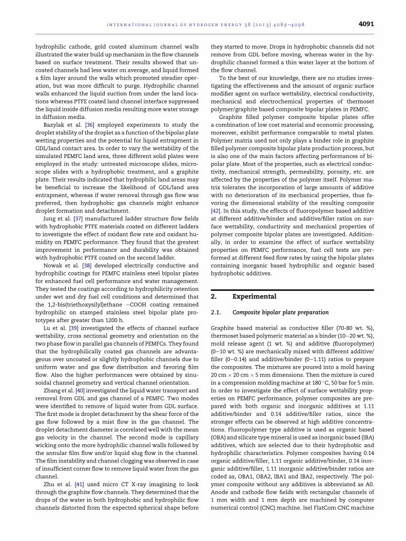
Fig. 2 e Effect of organic basedadditive/filler ratio onsurface
wettability and conductivity of polymer composite bipolar
plates.
3. Results and discussion
3.1. Effect of organic based additive/filler ratio onpolymer composite bipolar plate properties
Fig. 2 shows the surface wettability properties of the com-
posite plates with different additive/filler contents. The sur-
face hydrophobicity gets stronger with increasing additive/
filler amount, due to the strong hydrophobic properties of
fluoropolymer based additive as observed in Fig. 2. Surface
energy and contact resistance of bipolar plates are important
factors affecting cell performance particularly at high current
densities, since water produced by the cathode reaction
should be immediately removed to avoid flooding and power
degradation due to catalyst submergence [43]. Graphite is also
hydrophobic and has an ordered domain structure [44,45].
This characteristic is important for the improvement of fuel
cell system efficiency, because high flow rates result in low
oxidant utilization and large power consumption for driving
an air compressor or blower to supply air to the fuel cell in the
case of using air as an oxidant [46].
The variation of through plane conductivity with respect to
organic based additive/filler ratios is shown in Fig. 2. The
amount of the thermoset resin is fixed in all the composites
for comparison. As it can be seen in the Fig. 2, the conductivity
of the samples decrease with the increase in additive/filler
ratios, due to a decrease in the amount of conductive filler in
the composite structure.
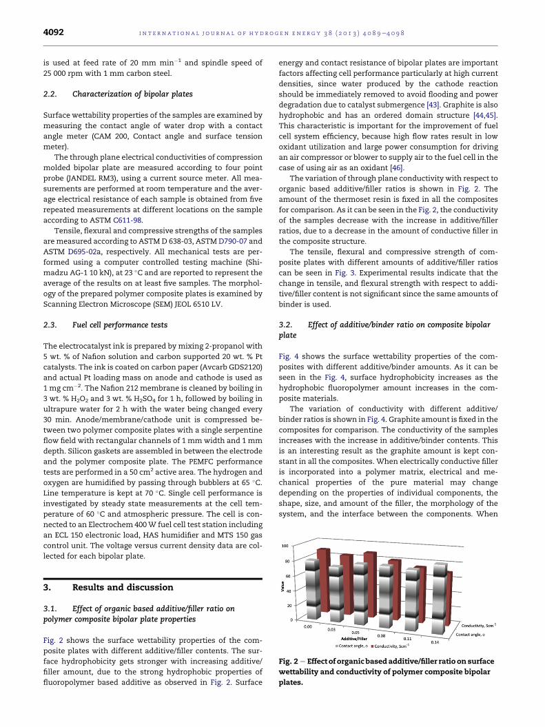
The tensile, flexural and compressive strength of com-
posite plates with different amounts of additive/filler ratios
can be seen in Fig. 3. Experimental results indicate that the
change in tensile, and flexural strength with respect to addi-
tive/filler content is not significant since the same amounts of
binder is used.
3.2. Effect of additive/binder ratio on composite bipolarplate
Fig. 4 shows the surface wettability properties of the com-
posites with different additive/binder amounts. As it can be
seen in the Fig. 4, surface hydrophobicity increases as the
hydrophobic fluoropolymer amount increases in the com-
posite materials.
The variation of conductivity with different additive/
binder ratios is shown in Fig. 4. Graphite amount is fixed in the
composites for comparison. The conductivity of the samples
increases with the increase in additive/binder contents. This
is an interesting result as the graphite amount is kept con-
stant in all the composites. When electrically conductive filler
is incorporated into a polymer matrix, electrical and me-
chanical properties of the pure material may change
depending on the properties of individual components, the
shape, size, and amount of the filler, the morphology of the
system, and the interface between the components. When
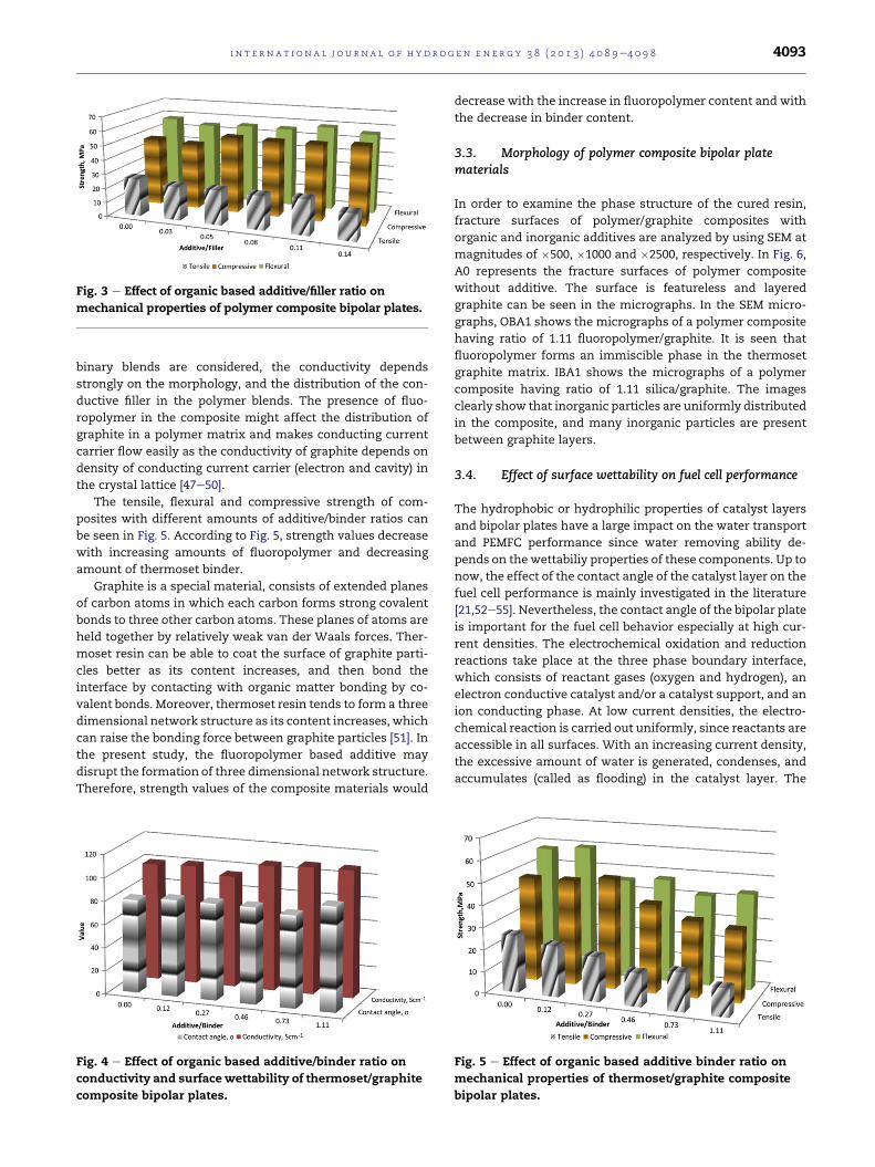
Fig. 3 e Effect of organic based additive/filler ratio on
mechanical properties of polymer composite bipolar plates.
i n t e r n a t i o n a l j o u r n a l o f h y d r o g e n en e r g y 3 8 ( 2 0 1 3 ) 4 0 8 9e4 0 9 8 4093
binary blends are considered, the conductivity depends
strongly on the morphology, and the distribution of the con-
ductive filler in the polymer blends. The presence of fluo-
ropolymer in the composite might affect the distribution of
graphite in a polymer matrix and makes conducting current
carrier flow easily as the conductivity of graphite depends on
density of conducting current carrier (electron and cavity) in
the crystal lattice [47e50].
The tensile, flexural and compressive strength of com-
posites with different amounts of additive/binder ratios can
be seen in Fig. 5. According to Fig. 5, strength values decrease
with increasing amounts of fluoropolymer and decreasing
amount of thermoset binder.
Graphite is a special material, consists of extended planes
of carbon atoms in which each carbon forms strong covalent
bonds to three other carbon atoms. These planes of atoms are
held together by relatively weak van der Waals forces. Ther-
moset resin can be able to coat the surface of graphite parti-
cles better as its content increases, and then bond the
interface by contacting with organic matter bonding by co-
valent bonds. Moreover, thermoset resin tends to form a three
dimensional network structure as its content increases, which
can raise the bonding force between graphite particles [51]. In
the present study, the fluoropolymer based additive may
disrupt the formation of three dimensional network structure.
Therefore, strength values of the composite materials would
Fig. 4 e Effect of organic based additive/binder ratio on
conductivity and surface wettability of thermoset/graphite
composite bipolar plates.
decrease with the increase in fluoropolymer content and with
the decrease in binder content.
3.3. Morphology of polymer composite bipolar platematerials
In order to examine the phase structure of the cured resin,
fracture surfaces of polymer/graphite composites with
organic and inorganic additives are analyzed by using SEM at
magnitudes of �500, �1000 and �2500, respectively. In Fig. 6,
A0 represents the fracture surfaces of polymer composite
without additive. The surface is featureless and layered
graphite can be seen in the micrographs. In the SEM micro-
graphs, OBA1 shows the micrographs of a polymer composite
having ratio of 1.11 fluoropolymer/graphite. It is seen that
fluoropolymer forms an immiscible phase in the thermoset
graphite matrix. IBA1 shows the micrographs of a polymer
composite having ratio of 1.11 silica/graphite. The images
clearly show that inorganic particles are uniformly distributed
in the composite, and many inorganic particles are present
between graphite layers.
3.4. Effect of surface wettability on fuel cell performance
The hydrophobic or hydrophilic properties of catalyst layers
and bipolar plates have a large impact on the water transport
and PEMFC performance since water removing ability de-
pends on the wettabiliy properties of these components. Up to
now, the effect of the contact angle of the catalyst layer on the
fuel cell performance is mainly investigated in the literature
[21,52e55]. Nevertheless, the contact angle of the bipolar plate
is important for the fuel cell behavior especially at high cur-
rent densities. The electrochemical oxidation and reduction
reactions take place at the three phase boundary interface,
which consists of reactant gases (oxygen and hydrogen), an
electron conductive catalyst and/or a catalyst support, and an
ion conducting phase. At low current densities, the electro-
chemical reaction is carried out uniformly, since reactants are
accessible in all surfaces. With an increasing current density,
the excessive amount of water is generated, condenses, and
accumulates (called as flooding) in the catalyst layer. The
Fig. 5 e Effect of organic based additive binder ratio on
mechanical properties of thermoset/graphite composite
bipolar plates.
Fig. 6 e SEM micrographs of polymer composites bipolar plates.
i n t e rn a t i o n a l j o u r n a l o f h y d r o g e n en e r g y 3 8 ( 2 0 1 3 ) 4 0 8 9e4 0 9 84094
reaction rate is limited by the transport rate of oxygen to the
reaction sites. The oxygen transport properties of the catalyst
layer are affected by the accumulation of liquid water within
the cathode and mainly governed by the permeability,
porosity, the capillary pressure saturation relation and the
contact angle of surface of catalyst layer and bipolar plate. The
capillary forces are strongly related to the contact angle.
The perfect wettability is obtained with 0� contact angle;
that is the water suddenly spreads over a solid surface due to
high surface energy. Hydrophilic channel improve capillary
driven water flow but it can increase water retention in
channels. When the channel contact angle is greater than 90�,the water tends to bead up on the surface in the form of dis-
crete droplets. The partially wetting is obtained between 45
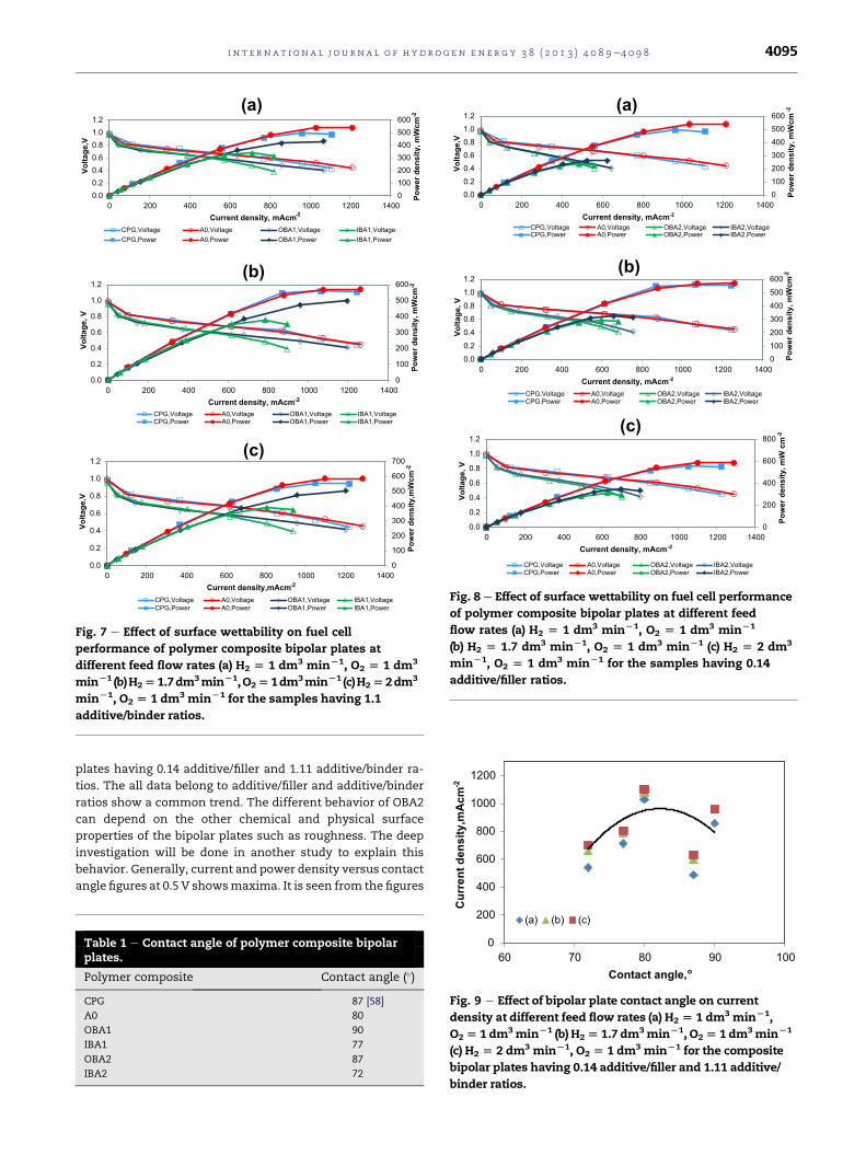
and 90� contact angles.Fig. 7 shows the effect of surface wettability on fuel cell
performance of polymer composite bipolar plates in partially
wetting region at different feed flow rates (a)
H2 ¼ 1 dm3 min�1, O2 ¼ 1 dm3 min�1 (b) H2 ¼ 1.7 dm3 min�1,
O2 ¼ 1 dm3 min�1 (c) H2 ¼ 2 dm3 min�1 O2 ¼ 1 dm3 min�1 for
the samples having 1.1 additive/binder ratios. The excess ox-
ygen without limitation was used. The performances data
belong to commercial pure graphite bipolar plate (CPG) are
also shown in Fig. 7 for comparison. Table 1 shows the contact
angle of polymer composite materials. In all feed flow rates, at
low current densities, the single cells exhibited almost the
same performance. At intermediate and high current den-
sities, composite without additives and commercial graphite
bipolar plate showed higher performance than the bipolar
plates containing organic or inorganic based additives. At high
current rates, bipolar plate with organic additive (i.e. with
higher contact angle) has higher performance than the bipolar
plate having inorganic additive (i.e. with lower contact angle).
The bipolar plate with inorganic additive and lower contact
angle could retain more water produced by the cathode re-
action and supplied through a humidifier, resulting in the
mass transfer polarization [56].
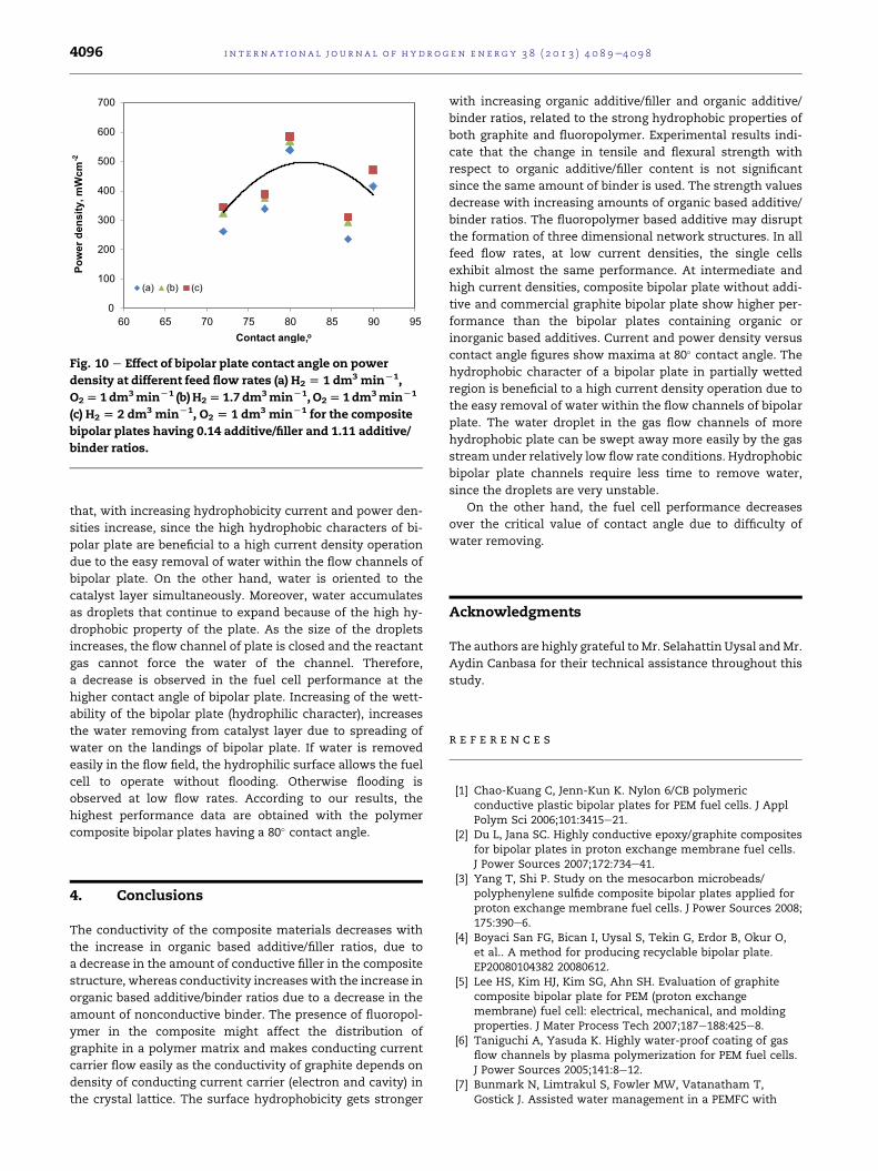
Fig. 8 shows the effect of surface properties on fuel cell
performance of polymer composite bipolar plates at different
feed flow rates (a) H2 ¼ 1 dm3 min�1, O2 ¼ 1 dm3 min�1 (b)
H2 ¼ 1.7 dm3 min�1, O2 ¼ 1 dm3 min�1 (c) H2 ¼ 2 dm3 min�1
O2 ¼ 1 dm3 min�1 for the samples having 0.14 additive/filler
ratios. The data are obtained also in partially wetting region.
The same trend in Fig. 7 is also observed in all feed flow rates.
Due to the easy removal of water within the flow channels of
the bipolar plate with increasing hydrophobicity, hydrophobic
bipolar plates show higher current and power densities. In
a fuel cell stack, gas flow channels blocked by condensed
liquid water and results in a serious degradation as electrode
area, reactant starvation and humidifying temperature in-
creases. Therefore, the better fuel cell performance is
obtained by partially hydrophilic composites than hydrophilic
ones. The results are consistent with the literature [57].
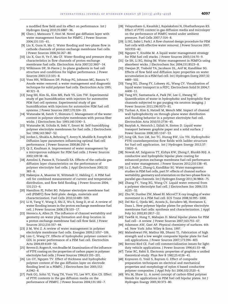
Fig. 9 and Fig. 10 show the effect of the bipolar plate contact
angles on current density and power density, respectively at
different feed flow rates (a) H2 ¼ 1 dm3 min�1,
O2 ¼ 1 dm3 min�1 (b) H2 ¼ 1.7 dm3 min�1, O2 ¼ 1 dm3 min�1 (c)
H2 ¼ 2 dm3 min�1 O2 ¼ 1 dm3 min�1 for the composite bipolar
0100200300400500600
0.00.20.40.60.81.01.2
0 200 400 600 800 1000 1200 1400
Po
we
r d
en
sity
, m
Wc
m-2
Vo
ltag
e,V
Current density, mAcm-2
(a)
CPG,Voltage A0,Voltage OBA1,Voltage IBA1,VoltageCPG,Power A0,Power OBA1,Power IBA1,Power
0
100
200
300
400
500
600
0.0
0.2
0.4
0.6
0.8
1.0
1.2
0 200 400 600 800 1000 1200 1400
Po
we
r d
en
sity
, m
Wc
m-2
Vo
ltag
e, V
Current density, mAcm-2
(b)
CPG,Voltage A0,Voltage OBA1,Voltage IBA1,VoltageCPG,Power A0,Power OBA1,Power IBA1,Power
0
100
200
300
400
500
600
700
0.0
0.2
0.4
0.6
0.8
1.0
1.2
0 200 400 600 800 1000 1200 1400
Po
we
r d
en
sity
,mW
cm
-2
Vo
ltag
e,V
Current density,mAcm-2
(c)
CPG,Voltage A0,Voltage OBA1,Voltage IBA1,VoltageCPG,Power A0,Power OBA1,Power IBA1,Power
Fig. 7 e Effect of surface wettability on fuel cell
performance of polymer composite bipolar plates at
different feed flow rates (a) H2 [ 1 dm3 minL1, O2 [ 1 dm3
minL1 (b)H2[1.7dm3minL1,O2[1dm3minL1 (c)H2[2dm3
minL1, O2 [ 1 dm3 minL1 for the samples having 1.1
additive/binder ratios.
0100200300400500600
0.00.20.40.60.81.01.2
0 200 400 600 800 1000 1200 1400
Po
we
r d
en
sity
, m
Wc
m-2
Vo
lta
ge
,V
Current density, mAcm-2
(a)
CPG,Voltage A0,Voltage OBA2,Voltage IBA2,VoltageCPG,Power A0,Power OBA2,Power IBA2,Power
0100200300400500600
0.00.20.40.60.81.01.2
0 200 400 600 800 1000 1200 1400
Po
we
r d
en
sity
, m
Wc
m-2
Vo
lta
ge
, V
Current density, mAcm-2
(b)
CPG,Voltage A0,Voltage OBA2,Voltage IBA2,VoltageCPG,Power A0,Power OBA2,Power IBA2,Power
0
200
400
600
800
0.0
0.2
0.4
0.6
0.8
1.0
1.2
0 200 400 600 800 1000 1200 1400
Po
wer d
en
sity, m
W cm
-2
Vo
ltag
e, V
Current density, mA cm-2
(c)
CPG,Voltage A0,Voltage OBA2,Voltage IBA2,VoltageCPG,Power A0,Power OBA2,Power IBA2,Power
Fig. 8 e Effect of surface wettability on fuel cell performance
of polymer composite bipolar plates at different feed
flow rates (a) H2 [ 1 dm3 minL1, O2 [ 1 dm3 minL1
(b) H2 [ 1.7 dm3 minL1, O2 [ 1 dm3 minL1 (c) H2 [ 2 dm3
minL1, O2 [ 1 dm3 minL1 for the samples having 0.14
additive/filler ratios.
400
600
800
1000
1200
rre
nt d
en
sit
y,m
Ac
m-2
i n t e r n a t i o n a l j o u r n a l o f h y d r o g e n en e r g y 3 8 ( 2 0 1 3 ) 4 0 8 9e4 0 9 8 4095
plates having 0.14 additive/filler and 1.11 additive/binder ra-
tios. The all data belong to additive/filler and additive/binder
ratios show a common trend. The different behavior of OBA2
can depend on the other chemical and physical surface
properties of the bipolar plates such as roughness. The deep
investigation will be done in another study to explain this
behavior. Generally, current and power density versus contact
angle figures at 0.5 V showsmaxima. It is seen from the figures
Table 1 e Contact angle of polymer composite bipolarplates.
Polymer composite Contact angle (�)
CPG 87 [58]
A0 80
OBA1 90
IBA1 77
OBA2 87
IBA2 72
0
200
60 70 80 90 100
Cu
Contact angle,o
(a) (b) (c)
Fig. 9 e Effect of bipolar plate contact angle on current
density at different feed flow rates (a) H2 [ 1 dm3 minL1,
O2[ 1 dm3minL1 (b) H2[ 1.7 dm3minL1, O2[ 1 dm3minL1
(c) H2 [ 2 dm3 minL1, O2 [ 1 dm3 minL1 for the composite
bipolar plates having 0.14 additive/filler and 1.11 additive/
binder ratios.
0
100
200
300
400
500
600
700
60 65 70 75 80 85 90 95
Po
we
r d
en
sit
y, m
Wcm
-2
Contact angle,o
(a) (b) (c)
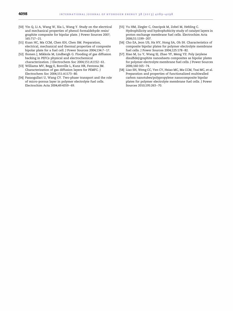
Fig. 10 e Effect of bipolar plate contact angle on power
density at different feed flow rates (a) H2 [ 1 dm3 minL1,
O2[ 1dm3minL1 (b) H2[ 1.7 dm3minL1, O2[1dm3minL1
(c) H2 [ 2 dm3 minL1, O2 [ 1 dm3 minL1 for the composite
bipolar plates having 0.14 additive/filler and 1.11 additive/
binder ratios.
i n t e rn a t i o n a l j o u r n a l o f h y d r o g e n en e r g y 3 8 ( 2 0 1 3 ) 4 0 8 9e4 0 9 84096
that, with increasing hydrophobicity current and power den-
sities increase, since the high hydrophobic characters of bi-
polar plate are beneficial to a high current density operation
due to the easy removal of water within the flow channels of
bipolar plate. On the other hand, water is oriented to the
catalyst layer simultaneously. Moreover, water accumulates
as droplets that continue to expand because of the high hy-
drophobic property of the plate. As the size of the droplets
increases, the flow channel of plate is closed and the reactant
gas cannot force the water of the channel. Therefore,
a decrease is observed in the fuel cell performance at the
higher contact angle of bipolar plate. Increasing of the wett-
ability of the bipolar plate (hydrophilic character), increases
the water removing from catalyst layer due to spreading of
water on the landings of bipolar plate. If water is removed
easily in the flow field, the hydrophilic surface allows the fuel
cell to operate without flooding. Otherwise flooding is
observed at low flow rates. According to our results, the
highest performance data are obtained with the polymer
composite bipolar plates having a 80� contact angle.
4. Conclusions
The conductivity of the composite materials decreases with
the increase in organic based additive/filler ratios, due to
a decrease in the amount of conductive filler in the composite
structure, whereas conductivity increaseswith the increase in
organic based additive/binder ratios due to a decrease in the
amount of nonconductive binder. The presence of fluoropol-
ymer in the composite might affect the distribution of
graphite in a polymer matrix and makes conducting current
carrier flow easily as the conductivity of graphite depends on
density of conducting current carrier (electron and cavity) in
the crystal lattice. The surface hydrophobicity gets stronger
with increasing organic additive/filler and organic additive/
binder ratios, related to the strong hydrophobic properties of
both graphite and fluoropolymer. Experimental results indi-
cate that the change in tensile and flexural strength with
respect to organic additive/filler content is not significant
since the same amount of binder is used. The strength values
decrease with increasing amounts of organic based additive/
binder ratios. The fluoropolymer based additive may disrupt
the formation of three dimensional network structures. In all
feed flow rates, at low current densities, the single cells
exhibit almost the same performance. At intermediate and
high current densities, composite bipolar plate without addi-
tive and commercial graphite bipolar plate show higher per-
formance than the bipolar plates containing organic or
inorganic based additives. Current and power density versus
contact angle figures show maxima at 80� contact angle. The
hydrophobic character of a bipolar plate in partially wetted
region is beneficial to a high current density operation due to
the easy removal of water within the flow channels of bipolar
plate. The water droplet in the gas flow channels of more
hydrophobic plate can be swept away more easily by the gas
stream under relatively low flow rate conditions. Hydrophobic
bipolar plate channels require less time to remove water,
since the droplets are very unstable.
On the other hand, the fuel cell performance decreases
over the critical value of contact angle due to difficulty of
water removing.
Acknowledgments
The authors are highly grateful toMr. Selahattin Uysal andMr.
Aydin Canbasa for their technical assistance throughout this
study.
r e f e r e n c e s
[1] Chao-Kuang C, Jenn-Kun K. Nylon 6/CB polymericconductive plastic bipolar plates for PEM fuel cells. J ApplPolym Sci 2006;101:3415e21.
[2] Du L, Jana SC. Highly conductive epoxy/graphite compositesfor bipolar plates in proton exchange membrane fuel cells.J Power Sources 2007;172:734e41.
[3] Yang T, Shi P. Study on the mesocarbon microbeads/polyphenylene sulfide composite bipolar plates applied forproton exchange membrane fuel cells. J Power Sources 2008;175:390e6.
[4] Boyaci San FG, Bican I, Uysal S, Tekin G, Erdor B, Okur O,et al.. A method for producing recyclable bipolar plate.EP20080104382 20080612.
[5] Lee HS, Kim HJ, Kim SG, Ahn SH. Evaluation of graphitecomposite bipolar plate for PEM (proton exchangemembrane) fuel cell: electrical, mechanical, and moldingproperties. J Mater Process Tech 2007;187e188:425e8.
[6] Taniguchi A, Yasuda K. Highly water-proof coating of gasflow channels by plasma polymerization for PEM fuel cells.J Power Sources 2005;141:8e12.
[7] Bunmark N, Limtrakul S, Fowler MW, Vatanatham T,Gostick J. Assisted water management in a PEMFC with
i n t e r n a t i o n a l j o u r n a l o f h y d r o g e n en e r g y 3 8 ( 2 0 1 3 ) 4 0 8 9e4 0 9 8 4097
a modified flow field and its effect on performance. Int JHydrogen Energ 2010;35:6887e96.
[8] Chen J, Matsuura T, Hori M. Novel gas diffusion layer withwater management function for PEMFC. J Power Sources2004;131:155e61.
[9] Liu X, Guoa H, Ma C. Water flooding and two-phase flow incathode channels of proton exchange membrane fuel cells.J Power Sources 2006;56:267e80.
[10] Liu X, Guo H, Ye F, Ma CF. Water flooding and pressure dropcharacteristics in flow channels of proton exchangemembrane fuel cells. Electrochim Acta 2007;52:3607e14.
[11] Wilkinson DP, St-Pierre J. In-plane gradients in fuel cellstructure and conditions for higher performance. J PowerSources 2003;113:101e8.
[12] Voss HH, Wilkinson DP, Pickup PG, Johnson MC, Basura V.Anode water removal: a water management and diagnostictechnique for solid polymer fuel cells. Electrochim Acta 1995;40:321e8.
[13] Jung SH, Kim SL, Kim MS, Park YS, Lim TW. Experimentalstudy of gas humidification with injectors for automotivePEM fuel cell systems. Experimental study of gashumidification with injectors for automotive PEM fuel cellsystems. J Power Sources 2007;170:324e33.
[14] Watanabe M, Satoh Y, Shimura C. Management of the watercontent in polymer electrolyte membranes with porous fiberwicks. J Electrochem Soc 1993;140:3190e3.
[15] Watanabe M, Uchida H, Seki Y, Emori M. Self-humidifyingpolymer electrolyte membranes for fuel cells. J ElectrochemSoc 1996;143:3847e52.
[16] Jordan L, Shukla A, Behrsing T, Avery N, Muddle B, Forsyth M.Diffusion layer parameters influencing optimal fuel cellperformance. J Power Sources 2000;86:250e4.
[17] Qi Z, Kaufman A. Improvement of water management bya microporous sublayer for PEM fuel cells. J Power Sources2002;109:38e46.
[18] Antolini E, Passos R, Ticianelli EA. Effects of the cathode gasdiffusion layer characteristics on the performance ofpolymer electrolyte fuel cells. J Appl Electrochem 2002;32:383e8.
[19] Hakenjos A, Muenter H, Wittstadt U, Hebling C. A PEM fuelcell for combined measurement of current and temperaturedistribution, and flow field flooding. J Power Sources 2004;131:213e6.
[20] Hamilton PJ, Pollet BG. Polymer electrolyte membrane fuelcell (PEMFC) flow field plate: design, materials andcharacterization. Fuel Cells 2010;10:489e509.
[21] Li H, Tang Y, Wang Z, Shi Z, Wu S, Song D, et al. A review ofwater flooding issues in the proton exchange membrane fuelcell. J Power Sources 2008;178:103e17.
[22] Herescu A, Allen JS. The influence of channel wettability andgeometry on water plug formation and drop location ina proton exchange membrane fuel cell flow field. J PowerSources 2012;216:337e44.
[23] Ji M, Wei Z. A review of water management in polymerelectrolyte membrane fuel cells. Energies 2009;2:1057e106.
[24] Lim C, Wang CY. Effects of hydrophobic polymer content inGDL in power performance of a PEM fuel cell. ElectrochimActa 2004;49:4149e56.
[25] BeversD, Rogers R, vonBradkeM. Examinationof the influenceof PTFE coating on the properties of carbon paper in polymerelectrolyte fuel cells. J Power Sources 1996;63:193e201.
[26] Lin GY, Nguyen TV. Effect of thickness and hydrophobicpolymer content of the gas diffusion layer on electrodeflooding level in a PEMFC. J Electrochem Soc 2005;152:A1942e8.
[27] Park GG, Sohn YJ, Yang TH, Yoon YG, Lee WY, Kim CS. Effectof PTFE contents in the gas diffusion media on theperformance of PEMFC. J Power Sources 2004;131:182e7.
[28] Velayutham G, Kaushik J, Rajalakshmi N, Dhathathreyan KS.Effect of PTFE content in gas diffusion media and microlayeron the performance of PEMFC tested under ambientpressure. Fuel Cells 2007;7:314e8.
[29] Li XG, Sabir I, Park J. A flow channel design procedure for PEMfuel cells with effective water removal. J Power Sources 2007;163:933e42.
[30] Nguyen T, Knobbe M. A liquid water management strategyfor PEM fuel cell stacks. J Power Sources 2003;114:70e9.
[31] Ge SH, Li XG, Hsing IM. Water management in PEMFCs usingabsorbent wicks. J Electrochem Soc 2004;151:B523e8.
[32] Owejan JP, Trabold TA, Jacobson DL, Arif M, Kandlikar SG.Effects of flow field and diffusion layer properties on wateraccumulation in a PEM fuel cell. Int J Hydrogen Energ 2007;32:4489e502.
[33] Yang XG, Zhang FY, Lubawy AL, Wang CY. Visualization ofliquid water transport in a PEFC. Electrochem Solid St 2004;7:A408e11.
[34] Tang HY, Santamaria A, Park JW, Lee C, Hwang W.Quantification of water in hydrophobic and hydrophilic flowchannels subjected to gas purging via neutron imaging. JPower Sources 2011;196:9373e81.
[35] Turhan A, Kim S, Hatzell M, Mench MM. Impact of channelwall hydrophobicity on through-plane water distributionand flooding behavior in a polymer electrolyte fuel cell.Electrochim Acta 2010;55:2734e45.
[36] Bazylak A, Heinrich J, Djilali N, Sinton D. Liquid watertransport between graphite paper and a solid surface. JPower Sources 2008;185:1147e53.
[37] Jung GB, Sun LM, Jao TC, Hunag BW, Liu YH. HydrophobicPTFE-coatedserpentine flow fields with ladder-structurefor fuel cell application. Int J Hydrogen Energy 2012;37:15820e6.
[38] Nowak AP, Salgueroa TT, Kirbya KW, Zhong F, Blunkb RHJ. Aconductive and hydrophilic bipolar plate coating forenhanced proton exchange membrane fuel cell performanceand water management. J Power Sources 2012;210:138e45.
[39] Lu Z, Rath C, Zhang G, Kandlikar SG. Water managementstudies in PEM fuel cells, part IV: effects of channel surfacewettability, geometry andorientationon the two-phaseflow inparallel gas channels. Int J Hydrogen Energy 2011;36:9864e75.
[40] Zhang FY, Yang XG, Wang CY. Liquid water removal froma polymer electrolyte fuel cell. J Electrochem Soc 2006;153:A225e32.
[41] ZhuW, Dunbar ZW, Masel RI. MicroCT X-ray imaging of watermovement in a PEM fuel cell. ECS Trans 2008;16:995e1000.
[42] Del Rio C, Ojeda MC, Acosta JL, Escudero MJ, Hontanon E,Daza L. New polymer bipolar plates for polymer electrolytemembrane fuel cells: synthesis and characterization. J ApplPoly Sci 2002;83:2817e22.
[43] Tawfik H, Hung Y, Mahajan D. Metal bipolar plates for PEMfuel celldA review. J Power Sources 2007;163:755e67.
[44] Adamson AW, Gast AP. Physical chemistry of surfaces. 6thed. New York: John Wiley & Sons; 1997.
[45] Maheshwari PH, Mathur RB, Dhami TL. Fabrication of highstrength and a low weight composite bipolar plate for fuelcell applications. J Power Sources 2007;173:394e403.
[46] Borroni-Bird CE. Fuel cell commercialization issues for light-duty vehicle applications. J Power Sources 1996;61:33e48.
[47] Tatar RC, Rabii S. Electronic properties of graphite-a unifiedtheoretical-study. Phys Rev B 1982;25:4126e41.
[48] Koysuren O, Yesil S, Bayram G. Effect of compositepreparation techniques on electrical and mechanicalproperties and morphology of nylon 6 based conductivepolymer composites. J Appl Poly Sci 2006;102:2520e6.
[49] Wu M, Shaw LL. A novel concept of carbon-filled polymerblends for applications in PEM fuel cell bipolar plates. Int JHydrogen Energy 2005;30:373e80.
i n t e rn a t i o n a l j o u r n a l o f h y d r o g e n en e r g y 3 8 ( 2 0 1 3 ) 4 0 8 9e4 0 9 84098
[50] Yin Q, Li A, Wang W, Xia L, Wang Y. Study on the electricaland mechanical properties of phenol formaldehyde resin/graphite composite for bipolar plate. J Power Sources 2007;165:717e21.
[51] Kuan HC, Ma CCM, Chen KH, Chen SM. Preparation,electrical, mechanical and thermal properties of compositebipolar plate for a fuel cell. J Power Sources 2004;134:7e17.
[52] Ihonen J, Mikkola M, Lindbergh G. Flooding of gas diffusionbacking in PEFCs physical and electrochemicalcharacterization. J Electrochem Soc 2004;151:A1152e61.
[53] Williams MV, Begg E, Bonville L, Kunz HR, Fentona JM.Characterization of gas diffusion layers for PEMFC. JElectrochem Soc 2004;151:A1173e80.
[54] Pasaogullari U, Wang CY. Two-phase transport and the roleof micro-porous layer in polymer electrolyte fuel cells.Electrochim Acta 2004;49:4359e69.
[55] Yu HM, Ziegler C, Oszcipok M, Zobel M, Hebling C.Hydrophilicity and hydrophobicity study of catalyst layers inproton exchange membrane fuel cells. Electrochim Acta2006;51:1199e207.
[56] Cho EA, Jeon US, Ha HY, Hong SA, Oh IH. Characteristics ofcomposite bipolar plates for polymer electrolyte membranefuel cells. J Power Sources 2004;125:178e82.
[57] Xiao M, Lu Y, Wang SJ, Zhao YF, Meng YZ. Poly (arylenedisulfide)/graphite nanosheets composites as bipolar platesfor polymer electrolyte membrane fuel cells. J Power Sources2006;160:165e74.
[58] Liao SH, Weng CC, Yen CY, Hsiao MC, Ma CCM, Tsai MC, et al.Preparation and properties of functionalized multiwalledcarbon nanotubes/polypropylene nanocomposite bipolarplates for polymer electrolyte membrane fuel cells. J PowerSources 2010;195:263e70.