Embed Size (px)
Citation preview
RJAV vol XI issue 2/2014 154 ISSN 1584-7284
Effect of Impact Mass on Tool Vibration and Cutting Performance During Turning of Hardened AISI4340 Steel P. SAM PAUL Associate Professor, Department of Mechanical Engineering, Karunya University, Karunya University, Coimbatore - 641114,Tamil Nadu; India.phone:09443496082; e-mail: [email protected]. A.S.VARADARAJAN Principal, Nehru college of Engineering &Research centre, Pambady, Thrissur - 680588, Kerala, India.Phone:09496176360;e-mail: [email protected]. Abstract: - A major apprehension in manufacturing industry is the tool vibration, which has considerable influence on productivity and production costs. The present investigation aims at developing impact mass for suppressing tool vibration and promoting better cutting performance during turning of hardened AISI4340 steel using hard metal insert with sculptured rake face. An impact mass used in this study consists of a concentrated mass made of brass of predetermined size and shape mounted on the shank of tool at a specific location. Impact mass was designed and the location of the damper on the tool shank for achieving effective damping was determined using computational analysis. When the damping mass was mounted on the tool shank, its vibration characteristics got altered and provided an inherent damping capability to the tool holder for suppressing tool vibration. Cutting experiments were conducted to study the influence of Impact mass on tool vibration and cutting performance during hard turning. From the results it was observed that the use of impact mass on tool shank reduces tool vibration and improves the cutting performance effectively. Keywords: - tool vibration, Impact mass, hard turning, Damping ratio, Surface roughness, tool wear, cutting force.
1. INTRODUCTION
Steel components that require high hardness as functional requirement are usually turned in the soft state, heat treated to the required hardness and then finish ground to the final dimension. This process cycle can be eliminated if the components could be directly machined to the final dimensions in the hardened state. This is possible by hard turning which replace the traditional process cycle of turning, heat treating, and finish grinding for assembly of hard wear resistant steel parts [1]. Hard turning can facilitate low process cost, low process time, better surface quality, and lower waste. In hard turning, the presence of tool vibration is a major issue and it leads to poor surface finish, cutting tool damage, increase the tool wear and production of irritating unacceptable noise [2]. Tool vibration is a dynamic instability of entire machining system, which is a result of interaction between metal cutting process and the dynamics of machine tool. In hard turning, tool wear and surface finish are considered as important parameters to evaluate the productivity of the machine tools as well as machined components [3]. Hard turning necessitates ultra hard cutting tools and extremely rigid machine tools [4].
Ultra hard cutting tools may be procured at a heightened cost. But the existing machine tool may not be rigid enough to support hard turning. Instead of going for a hard turning machine which is exceedingly costly, the cutting tool may be made more stiff and the scheme of using such damper can be successfully tried in such situations. In order to suppress tool vibration and to improve cutting performance, many types of dampers have been used in the past. Among the various types, impact damper, viscous damper and frictional damper are considered to be the most effective. Visco-elastic dampers have been used successfully along with boring and turning tools to suppress tool vibration [5], [6]. It is reported that Impact dampers can be used effectively for attenuation of tool vibration during metal cutting [7]. Also Vibration damping with impact dampers has been used in a wide variety of applications including television aerials [8], turbine blades [9], [10], structures[11], plates [12], tubing and shafts [13,14,15]. The advantages of impact dampers over traditional damping devices are that impact dampers are inexpensive, have simple designs that provide effective damping performance over a range of accelerations and frequencies [16], [17]. In addition, impact dampers are robust and
RJAV vol XI issue 2/2014 155 ISSN 1584-7284
operate in environments that are too harsh for other traditional damping methods [18].
Ema and Maruti [19], [20] developed an impact damper that consisted of a free mass in the form of a ring with a hole at the centre slightly greater than the diameter of the drill. From the results it was observed that impact damper reduces tool vibration effectively. Ramesh and Alwarsamy(2012)[21] suggested that, in impact damper, materials having high density produce more inertial mass which leads to better reduction in tool vibration. Sathish kumar et al., (2012) [22] developed a chatter suppression method based on particle damping technique to reduce chatter in boring tool and to improve surface finish. Metal powder granules (copper and lead) were filled into the boring tool through a hole drilled at the rear of the boring tool. It was observed that there was about 40% improvement in the surface finish when granules of copper with a size of 4.75mm were used to fill the hole in the boring bar.
Above mentioned studies indicate that the use of Impact damper has proved to be effective for different machining operation. Also from the literature it was observed that the concept of impact damper has not been applied in turning of hardened steel. In the present investigation, it is planned to develop an Impact damper and to study the effect of Impact mass on tool vibration, cutting force, surface roughness, tool wear using computational and experimental methods during hard turning of AISI4340 steel of 46 HRC using hard metal insert with sculptured rake face. When Impact mass was attached to the tool holder, there will be mutual impact interaction between the tool holder and the impact mass. This results in the absorption of the vibratory energy which further leads to reduction in amplitude of tool vibration. The size of the damping mass was determined by arithmetic analysis and computational analysis using ANSYS software was performed to arrive at a suitable location of the damper on the tool shank for achieving effective damping. Also cutting experiments were conducted to study the effect of impact mass during turning of AISI4340 steel of 46 HRC using hard metal insert with sculptured rake face. The Impact mass developed appears to hold promise as a means to suppress tool vibration and to improve the cutting performance. 2. SELECTION OF TOOL AND WORK MATERIAL
The tool holder used had the specification PSBNR 2525 M12. Multicoated hard metal inserts with sculptured rake face geometry with the specification SNMG 120408 MT TT5100 from
M/s.Taegu Tec were used in the present study. The work piece material was AISI 4340 steel which was hardened to 46 HRC by heat treatment. It is general purpose steel having a wide range of application in automobile and allied industries by virtue of its good hardenability enabling it to be used in fairly large sections[23]. Bars of 80mm diameter and 360 mm length were used in the present investigation. The chemical composition of AISI 4340 steel in weight percent is 0.41% C, 0.87% Mn, 0.28% Si, 1.83% Ni, 0.72% Cr ,0.20% Mo and rest Fe[24]. 3. DESIGN OF IMPACT MASS
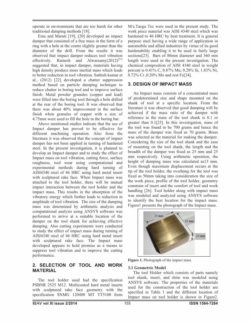
An Impact mass consists of a concentrated mass of predetermined size and shape mounted on the shank of tool at a specific location. From the literature it was observed that good damping will be achieved if the mass ratio of the damper with reference to the mass of the tool shank is 0.1 or greater than 0.1[25]. In this investigation, mass of the tool was found to be 700 grams and hence the mass of the damper was fixed as 70 grams. Brass was selected as the material for making the damper. Considering the size of the tool shank and the ease of mounting on the tool shank, the length and the breadth of the damper was fixed as 25 mm and 25 mm respectively. Using arithmetic operation, the height of damping mass was calculated as13 mm. Even though maximum displacement occurs at the tip of the tool holder, the overhang for the tool was fixed as 50mm taking into consideration the size of the work piece, profile of the tool holder, geometry constrain of insert and the comfort of tool and work handling [26]. Tool holder along with impact mass was modeled and analyzed using ANSYS software to identify the best location for the impact mass. Figure1 presents the photograph of the Impact mass.
Figure 1. Photograph of the impact mass
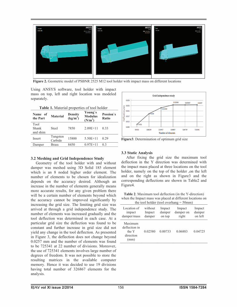
3.1 Geometric Model The tool Holder which consists of parts namely tool shank, insert, and shim was modeled using ANSYS software. The properties of the materials used for the construction of the tool holder are specified in Table 1 and the different location of Impact mass on tool holder is shown in Figure2.
RJAV vol XI issue 2/2014 156 ISSN 1584-7284
Using ANSYS software, tool holder with impact mass on top, left and right location was modeled separately.
Table 1. Material properties of tool holder Name of the Part Material Density
(kg/m3)
Young`s Modulus (N/m2)
Possion`s Ratio
Tool Shank and shim
Steel 7850 2.09E+11 0.33
Insert Tungsten Carbide 15800 5.50E+11 0.29
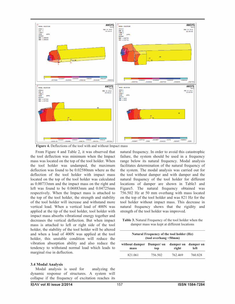
Damper Brass 8450 0.97E+11 0.3 3.2 Meshing and Grid Independence Study Geometry of the tool holder with and without damper was meshed using 3D Solid 185 element which is an 8 noded higher order element. The number of elements to be chosen for idealization depends on the accuracy desired. Although an increase in the number of elements generally means more accurate results, for any given problem there will be a certain number of elements beyond which the accuracy cannot be improved significantly by increasing the grid size. The limiting grid size was arrived at through a grid independence study. The number of elements was increased gradually and the tool deflection was determined in each case. At a particular grid size the deflection was found to be constant and further increase in grid size did not yield any change in the tool deflection. As presented in Figure 3, the deflection does not change beyond 0.0257 mm and the number of elements was found to be 725341 at 22 number of divisions. Moreover, the use of 725341 elements involves large number of degrees of freedom. It was not possible to store the resulting matrices in the available computer memory. Hence it was decided to use 19 divisions having total number of 326867 elements for the analysis.
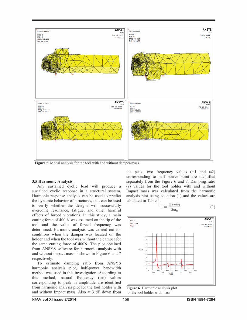
Figure3. Determination of optimum grid size 3.3 Static Analysis After fixing the grid size the maximum tool deflection in the Y direction was determined with the impact mass placed at three locations on the tool holder, namely on the top of the holder ,on the left and on the right as shown in Figure3 and the corresponding deflections are shown in Table2 and Figure4.
Table 2. Maximum tool deflection (in the Y-direction) when the Impact mass was placed at different locations on
the tool holder (tool overhang = 50mm) Location of
impact damper/mass
without Impact damper
Impact damper on top
Impact damper on
right
Impact damper on left
Maximum deflection in
the Y direction
(mm)
0.02580 0.00733 0.06883 0.04725
Figure 2. Geometric model of PSBNR 2525 M12 tool holder with impact mass on different locations
RJAV vol XI issue 2/2014 157 ISSN 1584-7284
From Figure 4 and Table 2, it was observed that the tool deflection was minimum when the Impact mass was located on the top of the tool holder. When the tool holder was undamped, the maximum deflection was found to be 0.02580mm where as the deflection of the tool holder with impact mass located on the top of the tool holder was calculated as 0.00733mm and the impact mass on the right and left was found to be 0.06883mm and 0.04725mm respectively. When the Impact mass is attached to the top of the tool holder, the strength and stability of the tool holder will increase and withstand more vertical load. When a vertical load of 400N was applied at the tip of the tool holder, tool holder with impact mass absorbs vibrational energy together and decreases the vertical deflection. But when impact mass is attached to left or right side of the tool holder, the stability of the tool holder will be altered and when a load of 400N was applied at the tool holder, this unstable condition will reduce the vibration absorption ability and also reduce the tendency to withstand normal load which leads to marginal rise in deflection. 3.4 Modal Analysis Modal analysis is used for analyzing the dynamic response of structures. A system will collapse if the frequency of excitation reaches its
natural frequency. In order to avoid this catastrophic failure, the system should be used in a frequency range below its natural frequency. Modal analysis facilitates determination of the natural frequency of the system. The modal analysis was carried out for the tool without damper and with damper and the natural frequency of the tool holder for different locations of damper are shown in Table3 and Figure5. The natural frequency obtained was 756.502 Hz at 50 mm overhang with mass located on the top of the tool holder and was 821 Hz for the tool holder without impact mass. This decrease in natural frequency shows that the rigidity and strength of the tool holder was improved.
Table 3. Natural Frequency of the tool holder when the damper mass was kept at different locations
Natural Frequency of the tool holder (Hz) (tool overhang =50mm)
without damper mass
Damper/ on top
damper on right
damper on left
821.061 756.502 762.469 760.828
Figure 4. Deflections of the tool with and without Impact mass
RJAV vol XI issue 2/2014 158 ISSN 1584-7284
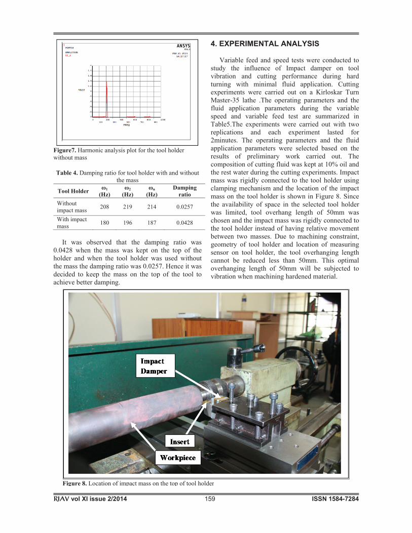
3.5 Harmonic Analysis Any sustained cyclic load will produce a sustained cyclic response in a structural system. Harmonic response analysis can be used to predict the dynamic behavior of structures, that can be used to verify whether the designs will successfully overcome resonance, fatigue, and other harmful effects of forced vibrations. In this study, a main cutting force of 400 N was assumed on the tip of the tool and the value of forced frequency was determined. Harmonic analysis was carried out for conditions when the damper was located on the holder and when the tool was without the damper for the same cutting force of 400N. The plot obtained from ANSYS software for harmonic analysis with and without impact mass is shown in Figure 6 and 7 respectively. To estimate damping ratio from ANSYS harmonic analysis plot, half-power bandwidth method was used in this investigation. According to this method, natural frequency ( n) values corresponding to peak in amplitude are identified from harmonic analysis plot for the tool holder with and without Impact mass. Also at 3 dB down from
the peak, two frequency values ( 1 and 2) corresponding to half power point are identified separately from the Figure 6 and 7. Damping ratio ( ) values for the tool holder with and without Impact mass was calculated from the harmonic analysis plot using equation (1) and the values are tabulated in Table 4.
(1)
Figure 6. Harmonic analysis plot for the tool holder with mass
Figure 5. Modal analysis for the tool with and without damper/mass
RJAV vol XI issue 2/2014 159 ISSN 1584-7284
Figure7. Harmonic analysis plot for the tool holder without mass Table 4. Damping ratio for tool holder with and without
the mass Tool Holder 1
(Hz) 2
(Hz) n
(Hz) Damping
ratio Without impact mass 208 219 214 0.0257
With impact mass 180 196 187 0.0428
It was observed that the damping ratio was 0.0428 when the mass was kept on the top of the holder and when the tool holder was used without the mass the damping ratio was 0.0257. Hence it was decided to keep the mass on the top of the tool to achieve better damping.
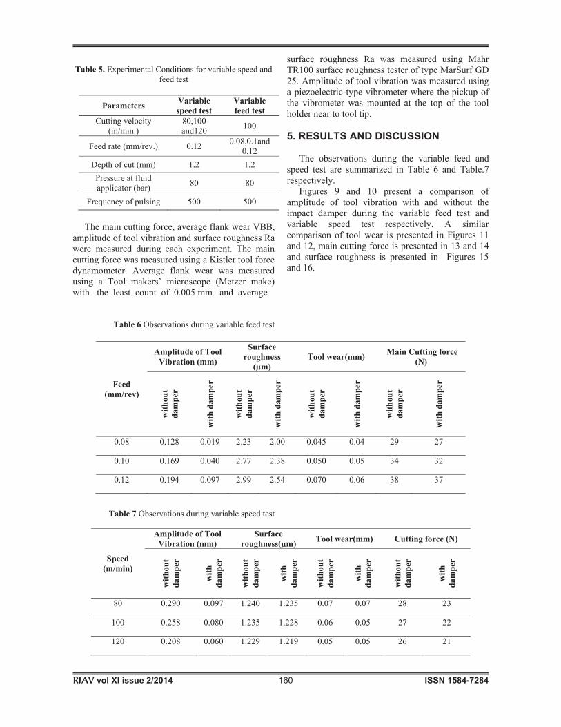
4. EXPERIMENTAL ANALYSIS Variable feed and speed tests were conducted to study the influence of Impact damper on tool vibration and cutting performance during hard turning with minimal fluid application. Cutting experiments were carried out on a Kirloskar Turn Master-35 lathe .The operating parameters and the fluid application parameters during the variable speed and variable feed test are summarized in Table5.The experiments were carried out with two replications and each experiment lasted for 2minutes. The operating parameters and the fluid application parameters were selected based on the results of preliminary work carried out. The composition of cutting fluid was kept at 10% oil and the rest water during the cutting experiments. Impact mass was rigidly connected to the tool holder using clamping mechanism and the location of the impact mass on the tool holder is shown in Figure 8. Since the availability of space in the selected tool holder was limited, tool overhang length of 50mm was chosen and the impact mass was rigidly connected to the tool holder instead of having relative movement between two masses. Due to machining constraint, geometry of tool holder and location of measuring sensor on tool holder, the tool overhanging length cannot be reduced less than 50mm. This optimal overhanging length of 50mm will be subjected to vibration when machining hardened material.
Figure 8. Location of impact mass on the top of tool holder
RJAV vol XI issue 2/2014 160 ISSN 1584-7284
Table 5. Experimental Conditions for variable speed and
feed test
Parameters Variable speed test
Variable feed test
Cutting velocity (m/min.)
80,100 and120 100
Feed rate (mm/rev.) 0.12 0.08,0.1and 0.12
Depth of cut (mm) 1.2 1.2 Pressure at fluid applicator (bar) 80 80
Frequency of pulsing 500 500
The main cutting force, average flank wear VBB, amplitude of tool vibration and surface roughness Ra were measured during each experiment. The main cutting force was measured using a Kistler tool force dynamometer. Average flank wear was measured using a Tool makers’ microscope (Metzer make) with the least count of 0.005 mm and average
Table 6 Observations during variable feed test
Table 7 Observations during variable speed test
surface roughness Ra was measured using Mahr TR100 surface roughness tester of type MarSurf GD 25. Amplitude of tool vibration was measured using a piezoelectric-type vibrometer where the pickup of the vibrometer was mounted at the top of the tool holder near to tool tip. 5. RESULTS AND DISCUSSION
The observations during the variable feed and speed test are summarized in Table 6 and Table.7 respectively.
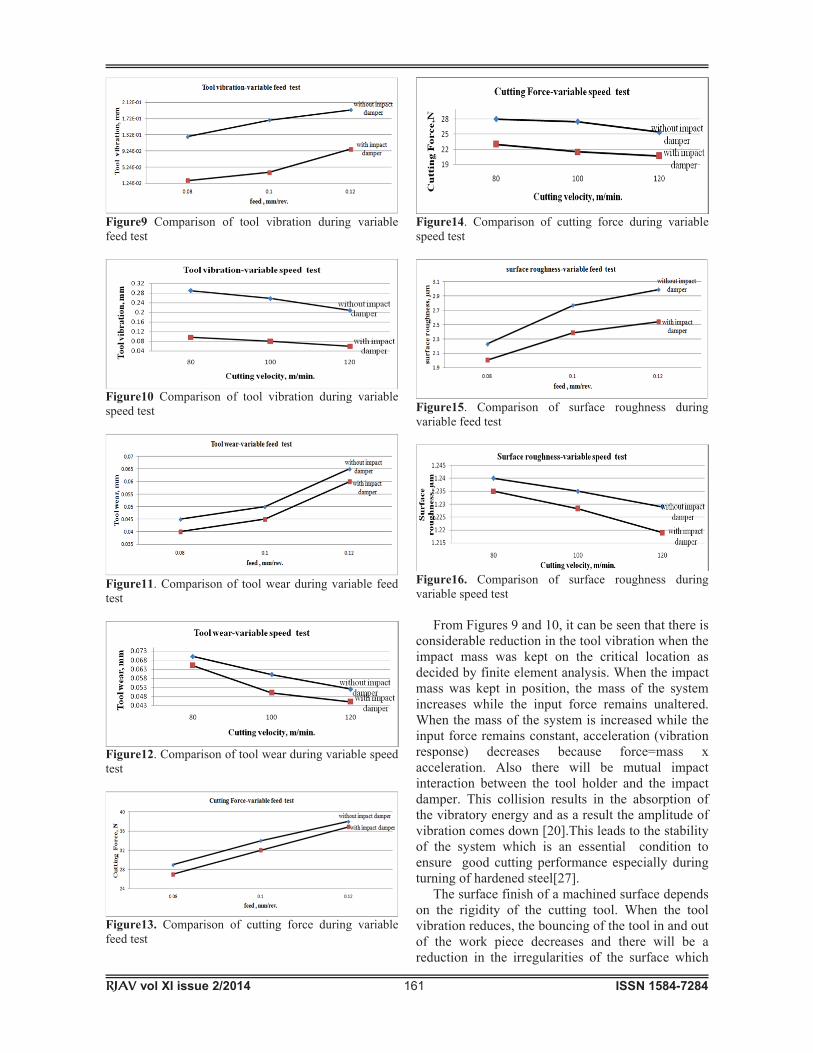
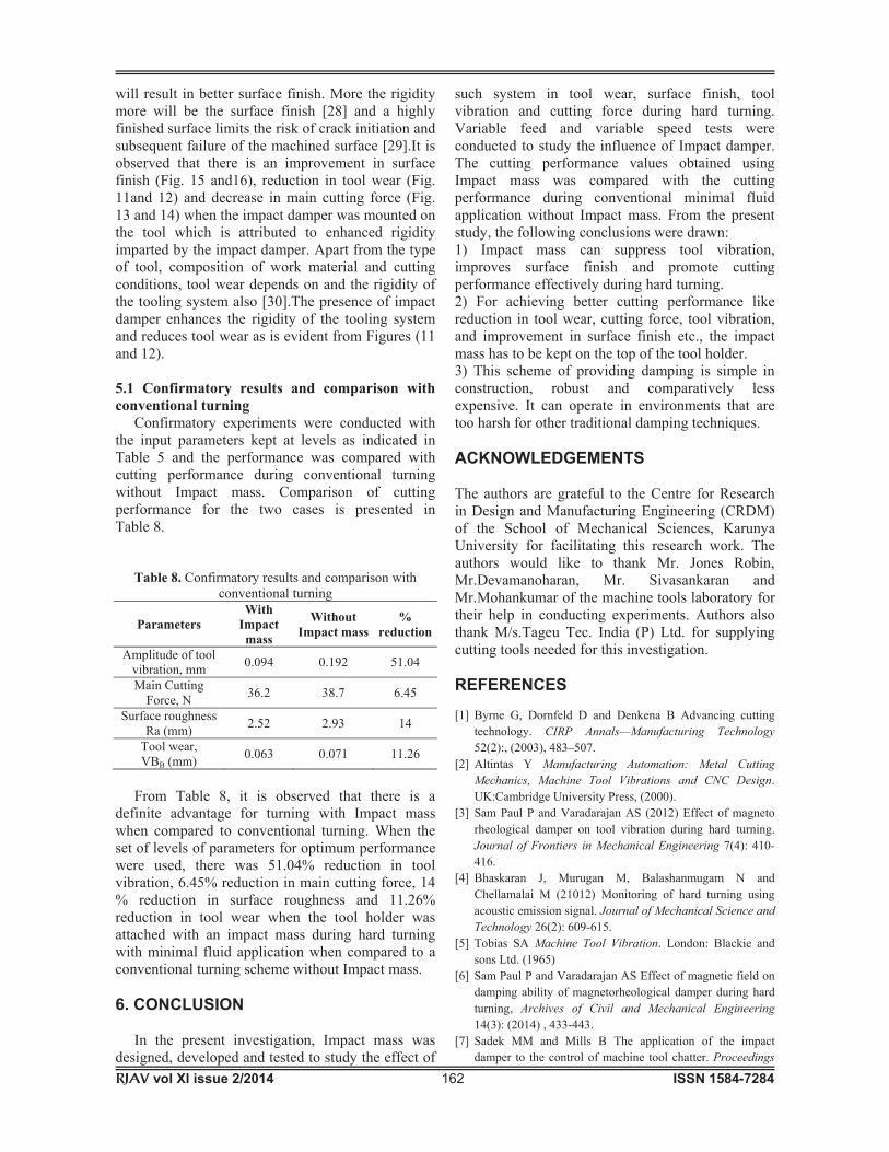
Figures 9 and 10 present a comparison of amplitude of tool vibration with and without the impact damper during the variable feed test and variable speed test respectively. A similar comparison of tool wear is presented in Figures 11 and 12, main cutting force is presented in 13 and 14 and surface roughness is presented in Figures 15 and 16.
Feed (mm/rev)
Amplitude of Tool Vibration (mm)
Surface roughness
(μm) Tool wear(mm) Main Cutting force
(N)
with
out
dam
per
with
dam
per
with
out
dam
per
with
dam
per
with
out
dam
per
with
dam
per
with
out
dam
per
with
dam
per
0.08 0.128 0.019 2.23 2.00 0.045 0.04 29 27
0.10 0.169 0.040 2.77 2.38 0.050 0.05 34 32
0.12 0.194 0.097 2.99 2.54 0.070 0.06 38 37
Speed (m/min)
Amplitude of Tool Vibration (mm)
Surface roughness(μm) Tool wear(mm) Cutting force (N)
with
out
dam
per
with
da
mpe
r
with
out
dam
per
with
da
mpe
r
with
out
dam
per
with
da
mpe
r
with
out
dam
per
with
da
mpe
r
80 0.290 0.097 1.240 1.235 0.07 0.07 28 23
100 0.258 0.080 1.235 1.228 0.06 0.05 27 22
120 0.208 0.060 1.229 1.219 0.05 0.05 26 21
RJAV vol XI issue 2/2014 161 ISSN 1584-7284
Figure9 Comparison of tool vibration during variable feed test
Figure10 Comparison of tool vibration during variable speed test
Figure11. Comparison of tool wear during variable feed test
Figure12. Comparison of tool wear during variable speed test
Figure13. Comparison of cutting force during variable feed test
Figure14. Comparison of cutting force during variable speed test
Figure15. Comparison of surface roughness during variable feed test
Figure16. Comparison of surface roughness during variable speed test From Figures 9 and 10, it can be seen that there is considerable reduction in the tool vibration when the impact mass was kept on the critical location as decided by finite element analysis. When the impact mass was kept in position, the mass of the system increases while the input force remains unaltered. When the mass of the system is increased while the input force remains constant, acceleration (vibration response) decreases because force=mass x acceleration. Also there will be mutual impact interaction between the tool holder and the impact damper. This collision results in the absorption of the vibratory energy and as a result the amplitude of vibration comes down [20].This leads to the stability of the system which is an essential condition to ensure good cutting performance especially during turning of hardened steel[27]. The surface finish of a machined surface depends on the rigidity of the cutting tool. When the tool vibration reduces, the bouncing of the tool in and out of the work piece decreases and there will be a reduction in the irregularities of the surface which
RJAV vol XI issue 2/2014 162 ISSN 1584-7284
will result in better surface finish. More the rigidity more will be the surface finish [28] and a highly finished surface limits the risk of crack initiation and subsequent failure of the machined surface [29].It is observed that there is an improvement in surface finish (Fig. 15 and16), reduction in tool wear (Fig. 11and 12) and decrease in main cutting force (Fig. 13 and 14) when the impact damper was mounted on the tool which is attributed to enhanced rigidity imparted by the impact damper. Apart from the type of tool, composition of work material and cutting conditions, tool wear depends on and the rigidity of the tooling system also [30].The presence of impact damper enhances the rigidity of the tooling system and reduces tool wear as is evident from Figures (11 and 12). 5.1 Confirmatory results and comparison with conventional turning Confirmatory experiments were conducted with the input parameters kept at levels as indicated in Table 5 and the performance was compared with cutting performance during conventional turning without Impact mass. Comparison of cutting performance for the two cases is presented in Table 8.
Table 8. Confirmatory results and comparison with conventional turning
Parameters With
Impact mass
Without Impact mass
% reduction
Amplitude of tool vibration, mm 0.094 0.192 51.04
Main Cutting Force, N 36.2 38.7 6.45
Surface roughness Ra (mm) 2.52 2.93 14
Tool wear, VBB (mm) 0.063 0.071 11.26
From Table 8, it is observed that there is a definite advantage for turning with Impact mass when compared to conventional turning. When the set of levels of parameters for optimum performance were used, there was 51.04% reduction in tool vibration, 6.45% reduction in main cutting force, 14 % reduction in surface roughness and 11.26% reduction in tool wear when the tool holder was attached with an impact mass during hard turning with minimal fluid application when compared to a conventional turning scheme without Impact mass. 6. CONCLUSION In the present investigation, Impact mass was designed, developed and tested to study the effect of
such system in tool wear, surface finish, tool vibration and cutting force during hard turning. Variable feed and variable speed tests were conducted to study the influence of Impact damper. The cutting performance values obtained using Impact mass was compared with the cutting performance during conventional minimal fluid application without Impact mass. From the present study, the following conclusions were drawn: 1) Impact mass can suppress tool vibration, improves surface finish and promote cutting performance effectively during hard turning. 2) For achieving better cutting performance like reduction in tool wear, cutting force, tool vibration, and improvement in surface finish etc., the impact mass has to be kept on the top of the tool holder. 3) This scheme of providing damping is simple in construction, robust and comparatively less expensive. It can operate in environments that are too harsh for other traditional damping techniques. ACKNOWLEDGEMENTS The authors are grateful to the Centre for Research in Design and Manufacturing Engineering (CRDM) of the School of Mechanical Sciences, Karunya University for facilitating this research work. The authors would like to thank Mr. Jones Robin, Mr.Devamanoharan, Mr. Sivasankaran and Mr.Mohankumar of the machine tools laboratory for their help in conducting experiments. Authors also thank M/s.Tageu Tec. India (P) Ltd. for supplying cutting tools needed for this investigation. REFERENCES [1] Byrne G, Dornfeld D and Denkena B Advancing cutting
technology. CIRP Annals—Manufacturing Technology 52(2):, (2003), 483–507.
[2] Altintas Y Manufacturing Automation: Metal Cutting Mechanics, Machine Tool Vibrations and CNC Design. UK:Cambridge University Press, (2000).
[3] Sam Paul P and Varadarajan AS (2012) Effect of magneto rheological damper on tool vibration during hard turning. Journal of Frontiers in Mechanical Engineering 7(4): 410-416.
[4] Bhaskaran J, Murugan M, Balashanmugam N and Chellamalai M (21012) Monitoring of hard turning using acoustic emission signal. Journal of Mechanical Science and Technology 26(2): 609-615.
[5] Tobias SA Machine Tool Vibration. London: Blackie and sons Ltd. (1965)
[6] Sam Paul P and Varadarajan AS Effect of magnetic field on damping ability of magnetorheological damper during hard turning, Archives of Civil and Mechanical Engineering 14(3): (2014) , 433-443.
[7] Sadek MM and Mills B The application of the impact damper to the control of machine tool chatter. Proceedings
RJAV vol XI issue 2/2014 163 ISSN 1584-7284
of the Seventh International Machine Tool and Die Research Conference, UK ,243–257, (1966).
[8] Kaper HG The behaviour of a spring mass system provided with a discontinuous dynamic vibration absorber. Applied Science Research Section A 5 (10): (1961) , 369–383.
[9] Duffy KP, Bagley RL and Mehmed O A self-tuning impact damper for rotating blades. NASA Tech Briefs TSPLEW-168333 : (2001), 1–15.
[10] Fowler BL, Flint EM and Olson SE Design methodology for particle damping. Proceedings of SPIE Conference on Smart Structures and Materials, USA, (2001), 1–12.
[11] Chatterjee S, Mallik AK and Ghosh A,On impact dampers for nonlinear vibrating systems. Journal of Sound and Vibration 187 (3), (1995) :403–420.
[12] Fricke JR Lodengraf damping-an advanced vibration damping technology. Journal of Sound and Vibration 34 (7), (2000): 22–27.
[13] Panossian HV Structural damping enhancement via non-obstructive particle damping technique. Journal of Vibration and Acoustics 114 (1), (1992) :101–105.
[14] Skipor E and Bain LJ Application of impact damping to rotary printing equipment. ASME Journal of Mechanical Design 102 (2), (1980): 338–343.
[15] Thomas MD, Knight WA and Sadek MM, The impact damper as a method improving cantilever boring bars. Journal of Engineering for Industry- Transactions of the ASME 97 (3), (1975) :859–866.
[16] Bapat CN and Sankar S,Single unit impact damper in free and forced vibration. Journal of Sound and Vibration 99(1), (1985) :85–94.
[17] Dokainish MA and Elmaraghy HV,Optimum design parameters for impact dampers. The ASME Publications Design Engineering and Technical Conference, USA, (1973), 611–617.
[18] Flint EM, Experimental measurements of particle damping effectiveness under centrifugal loads. Proceedings of the Fourth National Turbine Engine High Cycle Fatigue Conference, USAF, Monterey, CA, (1999), 1–6.
[19] Ema S and Marui E, Damping Characteristics on an Impact Damper and Its Application. International Journal of Machine Tools and Manufacture 36 (3), (1996): 293–306.
[20] Ema S and Marui E,Suppression of chatter vibration of boring tools using impact dampers. International Journal of Machine Tools & Manufacture 40(8), (2000): 1141–1156.
[21] Ramesh and Alwarsamy, Investigation of Modal Analysis in the Stability of Boring Tool using Double Impact Dampers Model Development. European Journal of Scientific Research 80 (2), (2012): 182-190.
[22] Sathish kumar B, Mohanasundaram KM and Senthil Kumar M, Experimental Studies on Impact of Particle Damping on Surface Roughness of Machined Components in Boring Operation. European Journal of Scientific Research 71(3), (2012): 327-337.
[23] Sam Paul P and Varadarajan AS, A multi-sensor fusion model based on an artificial neural network to predict tool wear during hard turning. Journal of Engineering Manufacture 226(5) (2012): 853-860.
[24] Sam Paul P and Varadarajan AS, Performance evaluation of hard turning of AISI 4340 steel with minimal fluid application in the presence of semi-solid lubricants. Journal of Engineering Tribology 227(7), (2013): 739-748.
[25] Kun.S.Marhadi and Vikram.K.kindra, Particle impact damping: effect of mass ratio, material and shape. Journal of sound and vibration 283(1-2), (2005): 433-448.
[26] Sam Paul P and Varadarajan AS, Analysis of Turning Tool holder with MR Fluid damper. Journal of Procedia Engineering 38, (2012): 2572-2578.
[27] Varadarajan AS, Philip PK and Ramamoorthy B, Investigations on hard turning with minimal fluid application (HTMF) and its comparison with dry and wet turning. International Journal of Machine Tools & Manufacture 42(2) (2002): 193–200.
[28] Chih-Cherng Chen, Nun-Ming Liu, Ko-Ta Chiang and Hua-Lun Chen, Experimental investigation of tool vibration and surface roughness in the precision end-milling process using the singular spectrum analysis. International Journal of Advanced Manufacturing Technology 63(5-8) (2012): 797-815.
[29] Paulo Davim J Machining of Hard materials. London:Springer(2011).
[30] Kesavan R and Vijaya Ramnath B Machine Tools. New Delhi: Laxmi Publications(2010).