Embed Size (px)
Citation preview
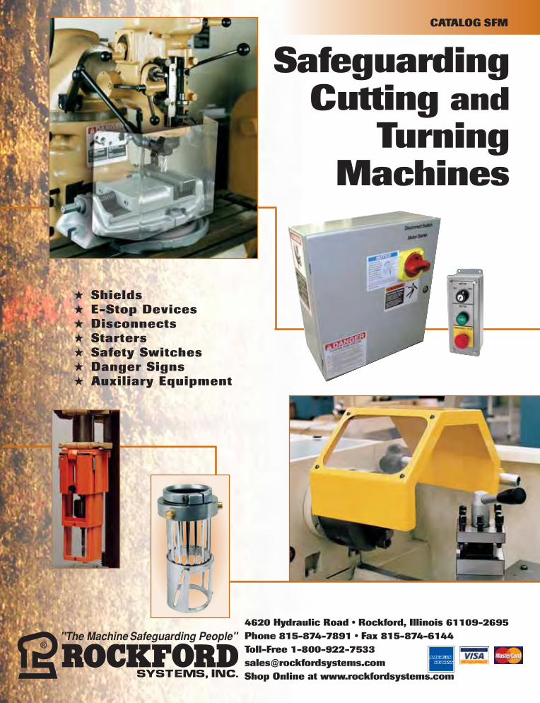
4620 Hydraulic Road • Rockford, Illinois 61109-2695
Phone 815-874-7891 • Fax 815-874-6144
Toll-Free 1-800-922-7533
Shop Online at www.rockfordsystems.com
★ Shields
★ E-Stop Devices
★ Disconnects
★ Starters
★ Safety Switches
★ Danger Signs
★ Auxiliary Equipment
SafeguardingCutting and
TurningMachines
CATALOG SFM

Copyright © 2007 by Rockford Systems, Inc. All rights reserved. Not to be reproduced in whole or in part without written permission. Litho in U.S.A.
YYOOUURR SSIINNGGLLEE--SSOOUURRCCEE SSUUPPPPLLIIEERR FFOORR AALLLL YYOOUURR SSAAFFEEGGUUAARRDDIINNGG RREEQQUUIIRREEMMEENNTTSS
Rockford Systems is one of the largest single-source suppliers of safety products for machinery. We offera total solution for all machine guarding and control requirements for updating machinery in the metal-fabricating, metal-cutting, woodworking, and robotic industries. Other markets served include packaging,textiles, material handling, and assembly machines. Our complete line of products allows industry to meetor exceed the OSHA and ANSI standards for machine guarding.
Our goals are to supply superior safety equipment which complies with the safety standards and to educateindividuals in positions of responsibility in these areas. To achieve these goals, we are always striving to findnew and better ways of providing equipment to safeguard personnel who work on or around machinery. Weoffer a variety of services to help make your plant as safe as possible. These include:
Design Engineering
Product developmentand engineering per-sonnel are constantlydeveloping new safe-guarding productswhich are compatiblewith today’s manufac-turing environment.
Installation of EquipmentHighly skilled installationcrews are available to providecomplete integration andinstallation services of safe-guarding systems in yourplant or to instruct your per-sonnel. These crews are highlyqualified and have manyhours of on-the-job experienceon all types of cutting andturning equipment.
Machine Surveys
Our sales personnelknow machinery,know what is requiredto meet the OSHA andANSI standards, andwhat it takes toupdate your machin-ery. Detailed surveyforms are used togather all the infor-mation required tobring your machineryup to the safety stan-dards and beyond.
Training SeminarsWe offer a series of monthly machine safeguarding seminars which educatethe employer/user on safety standards. These seminars use visual aids,machine demonstrations and hands-on experience so the student canlearn to interpret the performance language of the standards and regula-tions. Each person attending also receives CEUs (continuing educationunits) and a binder filled with information on machine safeguarding.Customized on-site seminars can also be provided at customer locations.
ProposalsAfter completing a machinesurvey, a detailed proposalis generated which coversthe safety equipment re-quired to meet or exceedOSHA and ANSI standards.
Rockford Systems, Inc. ★ Shop Online at www.rockfordsystems.com ★ SFM 3
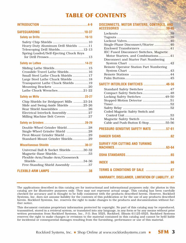
INTRODUCTION ..........................................4-9
SAFEGUARDING ......................................10-37Safety on Drills............................................10-13
Safety Chip Shields ....................................10Heavy-Duty Aluminum Drill Shields ..........11Telescoping Drill Shields........................12-13Spring-Loaded/Self-Ejecting Chuck Keys
for Drill Presses ........................................13
Safety on Lathes ..........................................14-22
Sliding Lathe Shields ..................................15Crosslide-Travel Lathe Shields....................16Small Steel Lathe Chuck Shields ................17Large Steel Lathe Chuck Shields ................18Transparent Lathe Chuck Shields ..............19Mounting Brackets ....................................20Lathe Chuck Wrenches..........................21-22
Safety on Mills ............................................23-27
Chip Shields for Bridgeport Mills ..........23-24Slide and Swing-Aside Shields ..............25-26Rear Shield Assemblies ..............................26Electrical Interlock Assembly ......................27Milling Machine Belt Covers ......................27
Safety on Grinders ........................................28-29
Double-Wheel Grinder Shield......................28Single-Wheel Grinder Shield ......................28Pivot-Mount Grinder Shield ........................29Standard-Mount Grinder Shields................29
Miscellaneous Shields ..................................30-37
Universal Ball & Socket Shields ............30-32Magnetic-Base Shields................................33Flexible-Arm/Snake-Arm/Gooseneck
Shields ................................................34-36Free-Standing Shield Assembly ..................37
FLEXIBLE-ARM LAMPS ..................................38
The applications described in this catalog are for instructional and informational purposes only; the photos in thiscatalog are for illustrative purposes only. They may not represent actual usage. This catalog has been carefullychecked for accuracy and is thought to be fully consistent with the products described herein. However, RockfordSystems, Inc. does not assume liability for the contents of this publication or for the use of any products describedherein. Rockford Systems, Inc. reserves the right to make changes to the products and documentation without fur-ther notice.
This document contains proprietary information protected by copyright. No part of this catalog may be reproduced,transmitted, stored in a retrieval system, or translated into any language, in any form or by any means without priorwritten permission from Rockford Systems, Inc., P.O. Box 5525, Rockford, Illinois 61125-0525. Rockford Systemsreserves the right to make changes or revisions to the material contained in this catalog and cannot be held liablefor incidental or consequential damages resulting from the furnishing, performance or use of this material.
TABLE OF CONTENTSDISCONNECTS, MOTOR STARTERS, CONTROLS, ANDACCESSORIES ........................................39-45
Lockouts ....................................................39Tagouts ......................................................39Lockout Valves............................................40Single-Phase Disconnect/Starter ................40Enclosed Transformers ..............................41IEC Fused Disconnect Switches, Magnetic
Motor Starters, and Combinations............41Disconnect and Starter Part Numbering
System Chart ..........................................42Remote Operator Station Part Numbering
System Chart ..........................................43Remote Stations ........................................44Palm Buttons..............................................45
SAFETY INTERLOCK SWITCHES ....................46-56Standard Safety Switches ..........................47Compact Safety Switches............................48Locking Safety Switches ........................49-50Stopped-Motion Detector ............................51Timer..........................................................52Safety Relay ....................................................52Coded Magnetic Safety Switch and
Control Unit ..................................................53Magnetic Safety Switch ..............................54Cable and Push-Button E-Stop..................55-56
PRESSURE-SENSITIVE SAFETY MATS ............57-61
DANGER SIGNS............................................62
SURVEY FOR CUTTING AND TURNINGMACHINES..............................................63-64
OSHA STANDARDS........................................65
INDEX ......................................................66
TERMS & CONDITIONS OF SALE ......................67
WARRANTY, DISCLAIMER, LIMITATION OF LIABILITY..67
4 SFM ★ Rockford Systems, Inc. ★ Call Toll-Free 1-800-922-7533 ★ Fax 815-874-6144
INTRODUCTION TO SAFEGUARDING CUTTING AND TURNING MACHINES
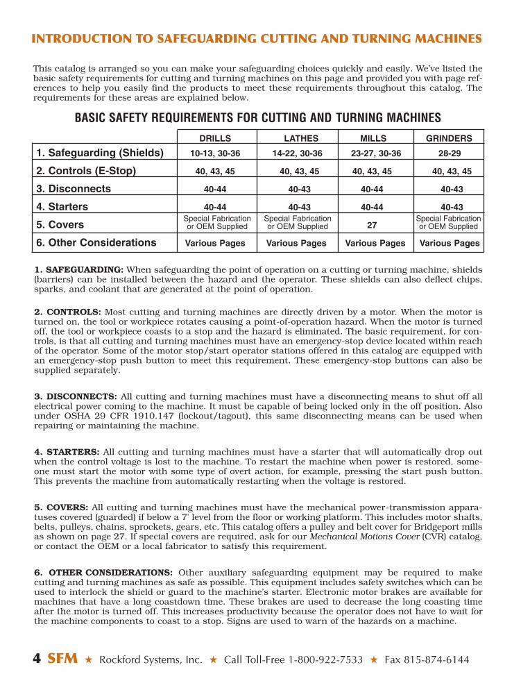
BASIC SAFETY REQUIREMENTS FOR CUTTING AND TURNING MACHINES
DRILLS LATHES MILLS GRINDERS
1. Safeguarding (Shields) 10-13, 30-36 14-22, 30-36 23-27, 30-36 28-29
2. Controls (E-Stop) 40, 43, 45 40, 43, 45 40, 43, 45 40, 43, 45
3. Disconnects 40-44 40-43 40-44 40-43
4. Starters 40-44 40-43 40-44 40-43
5. Covers 27
6. Other Considerations Various Pages Various Pages Various Pages Various Pages
1. SAFEGUARDING: When safeguarding the point of operation on a cutting or turning machine, shields(barriers) can be installed between the hazard and the operator. These shields can also deflect chips,sparks, and coolant that are generated at the point of operation.
2. CONTROLS: Most cutting and turning machines are directly driven by a motor. When the motor isturned on, the tool or workpiece rotates causing a point-of-operation hazard. When the motor is turnedoff, the tool or workpiece coasts to a stop and the hazard is eliminated. The basic requirement, for con-trols, is that all cutting and turning machines must have an emergency-stop device located within reachof the operator. Some of the motor stop/start operator stations offered in this catalog are equipped withan emergency-stop push button to meet this requirement. These emergency-stop buttons can also besupplied separately.
3. DISCONNECTS: All cutting and turning machines must have a disconnecting means to shut off allelectrical power coming to the machine. It must be capable of being locked only in the off position. Alsounder OSHA 29 CFR 1910.147 (lockout/tagout), this same disconnecting means can be used whenrepairing or maintaining the machine.
4. STARTERS: All cutting and turning machines must have a starter that will automatically drop outwhen the control voltage is lost to the machine. To restart the machine when power is restored, some-one must start the motor with some type of overt action, for example, pressing the start push button.This prevents the machine from automatically restarting when the voltage is restored.
5. COVERS: All cutting and turning machines must have the mechanical power-transmission appara-tuses covered (guarded) if below a 7' level from the floor or working platform. This includes motor shafts,belts, pulleys, chains, sprockets, gears, etc. This catalog offers a pulley and belt cover for Bridgeport millsas shown on page 27. If special covers are required, ask for our Mechanical Motions Cover (CVR) catalog,or contact the OEM or a local fabricator to satisfy this requirement.
6. OTHER CONSIDERATIONS: Other auxiliary safeguarding equipment may be required to make cutting and turning machines as safe as possible. This equipment includes safety switches which can beused to interlock the shield or guard to the machine’s starter. Electronic motor brakes are available formachines that have a long coastdown time. These brakes are used to decrease the long coasting timeafter the motor is turned off. This increases productivity because the operator does not have to wait forthe machine components to coast to a stop. Signs are used to warn of the hazards on a machine.
This catalog is arranged so you can make your safeguarding choices quickly and easily. We’ve listed thebasic safety requirements for cutting and turning machines on this page and provided you with page ref-erences to help you easily find the products to meet these requirements throughout this catalog. Therequirements for these areas are explained below.
Special Fabricationor OEM Supplied
Special Fabricationor OEM Supplied
Special Fabricationor OEM Supplied
Rockford Systems, Inc. ★ Shop Online at www.rockfordsystems.com ★ SFM 5
INTRODUCTION TO SAFEGUARDING CUTTING AND TURNING MACHINES
When safeguarding cutting and turning machines,the general requirements that apply to these typesof machines are in OSHA (Occupational Safety andHealth Administration) Title 29 of the Code ofFederal Regulations. The following is a list:1. An Act–Public Law 91-596, 91st Congress, S.
2193, December 29, 1970, Duties, Section5(a)(1)(2)(b)
2. OSHA 29 CFR sections that an employer (user)must comply with include:1910.211 Definitions 1910.212 General requirements for all machines1910.213 Woodworking machinery requirements1910.215 Abrasive wheel machinery1910.219 Mechanical power-transmission apparatus
3. OSHA 29 CFR 1910.147 The control of hazardous energy (lockout/tagout).
4. OSHA 29 CFR 1910.301-1910.399 Electrical
These publications can be acquired by contacting:U.S. Government Printing OfficeP.O. Box 371954Pittsburgh, PA 15250-7954(202) 512-1800 • http://bookstore.gpo.gov
The basic OSHA standard, 29 CFR 1910.212,states that any machine that creates a hazardmust be safeguarded to protect the operator andother employees. OSHA can also cite violationsusing other standards such as the ANSI(American National Standards Institute) B11series. The following is a list of applicable andrelated ANSI standards available at the printing ofthis publication.
B11.1 Mechanical Power PressesB11.2 Hydraulic Power PressesB11.3 Power Press BrakesB11.4 ShearsB11.5 Iron WorkersB11.6* Manual Turning Machines (Lathes)B11.7 Cold Headers and Cold FormersB11.8* Drilling, Milling, and Boring MachinesB11.9* Grinding MachinesB11.10* Metal Sawing MachinesB11.11* Gear and Spline Cutting MachinesB11.12 Roll Forming and Roll Bending MachinesB11.13 Automatic Screw/Bar and Chucking MachinesB11.14 Coil Slitting Machines/SystemsB11.15 Pipe, Tube, and Shape Bending MachinesB11.16 Metal Powder Compacting PressesB11.17 Horizontal Hydraulic Extrusion PressesB11.18 Coil Processing SystemsB11.19* Performance Criteria for SafeguardingB11.20 Manufacturing Systems/CellsB11.21 LasersB11.22* Turning Centers and CNC Turning MachinesB11.23* Machining Centers and CNC Milling, Drilling,
and Boring MachinesB11.24 Transfer MachinesB11.TR1 Ergonomic GuidelinesB11.TR2 Mist Control ConsiderationsB11.TR3* Risk Assessment and Risk ReductionR15.06 Robotic Safeguarding01.1* Woodworking Machinery
* ANSI Standards for Cutting and Turning Machines
These standards can be purchased by contacting: ANSI (American National Standards Institute, Inc.)25 West 43rd Street, 4th FloorNew York, New York 10036(212) 642-4900 • www.ansi.org
OR
AMT—The Association for Manufacturing Technology7901 Westpark DriveMcLean, Virginia 22102(703) 893-2900 • www.amtonline.org
Another good reference for safety on machine toolsis the following publication from the NationalSafety Council:
Safeguarding Concepts Illustrated—7th Edition
This publication can be purchased by contacting:National Safety Council1121 Spring Lake DriveItasca, IL 60143-32011-800-621-7619, ext. 2199 • www.nsc.org
Other sources that can be used for reference include:1. NFPA 79, Electrical Standard for Industrial
Machinery2. NEC (National Electrical Code) Handbook
These can be purchased by contacting:National Fire Protection Association1 Batterymarch ParkQuincy, MA 02169(617) 770-3000 • www.nfpa.org
3. NEMA (National Electrical ManufacturersAssociation)
1300 North 17th Street, Suite 1752Rosslyn, VA 22209(703) 841-3200 • www.nema.org
For additional safety information and assistance indevising, implementing or revising your safety pro-gram, please contact the machine manufacturer,your state and local safety councils, insurance car-riers, national trade associations, and your state’soccupational safety and health administration.
INTRODUCTION TO SAFEGUARDING CUTTING AND TURNING MACHINES
6 SFM ★ Rockford Systems, Inc. ★ Call Toll-Free 1-800-922-7533 ★ Fax 815-874-6144
This catalog offers a variety of equipment includinga complete line of shields (barriers), cord and pluglockouts, fused disconnect switches, magneticmotor starters, self-latching emergency stops,safety interlock switches, and accessories whichare available to meet the electrical energy sourceportion of these standards.
The shields (barriers) offered in this catalog are usu-ally installed on drilling machines, lathes, millingmachines, and grinding machines. Many of theshields can be used on other types of equipmentincluding woodworking machines. Most of theseshields are intended to deflect chips (swarf), sparks,coolant, or lubricant away from the operator andother employees in the machine area. In addition toprotection as a barrier, most shields provide visibilityto the point of operation.
Although these shields provide some degree of guard-ing for the operator, they cannot be consideredguards. When using these shields and before any ofthe shields illustrated in this catalog are moved fromtheir normally applied position, power must alwaysbe turned off.
In some cases, more than one type of shield permachine may be necessary to provide protection.For example, on lathes, a chuck shield may berequired along with a magnetic-base shield wherethe tool comes into contact with the workpiece.
This catalog offers several different types ofshields. When considering shielding for yourmachines, be sure to choose the shield that fitsyour machining applications and still maintainscurrent levels of productivity.
DRILLING MACHINESAs with other cutting machines, the operator mustbe protected from the rotating chuck and swarf thatis produced by the drill bit. Specially designedshields can be attached to the quill and used toprotect this area. A telescoping portion of the shieldcan retract as the drill bit comes down into theworkpiece. On larger gang or radial drills, a moreuniversal-type shield is usually applied.
The ANSI standard for drilling machines is ANSI B11.8.
LATHESThere are two main safety considerations for lathes(engine, turret, etc.). One is the rotating chuck thatcould catch the operator’s clothing, jewelry, hair, orhand and pull it into the machine. The other is thehazardous flying chips and coolant splash that are
generated at the point of operation (where the toolcontacts the workpiece being machined). To protectthese areas, two shields can be applied—one arounda portion of the chuck and the other at the point ofoperation. See the photo on page 15. Larger slidingshields can protect both areas, providing the work-piece is not too long.
On VTLs (vertical turret lathes), the safety concern isthe rotating table and the point-of-operation swarf.Special barriers may have to be fabricated around thetables of these machines; shields can be provided atthe point of operation. See page 35.
If railings are used to keep operators away from hazard areas, these railings must be 42" above thefloor or platform.
The ANSI standard for lathes is ANSI B11.6.
MILLING MACHINESThe main safety consideration for milling machines isthe swarf that is generated at the point of operation.Another safety concern is the tool cutter, which couldcatch operator’s clothing, jewelry, hair, or any otherpart of the body. Usually on smaller mills, the opera-tor and other employees in the machine area are protected by shields. These shields can be appliedaround the perimeter of the table or bed area or closeto the cutter, depending on the size of the workpieceand the application. On larger milling machines,operators are sometimes protected by location; how-ever, when working close to a cutting tool, operatorsmust be protected from swarf.
The ANSI standard for milling machines is ANSI B11.8.
GRINDING MACHINESShields are usually applied to grinding machines toprotect the operator from chips (swarf), sparks,coolant, or lubricant.
Other safety concerns for grinders are the adjustmentof the work rests and the adjustable tongues or endsof the peripheral members at the top of each wheel.Work rests shall be kept adjusted closely to the wheelwith a maximum opening of 1⁄8". The distance betweenthe wheel periphery and the adjustable tongue or theend of the peripheral member at the top shall neverexceed 1⁄4".
Grinding machines are covered by OSHA in 29 CFR1910.215. The ANSI standards for grinding machinesare B11.9 and B7.1.
INTRODUCTION TO SAFEGUARDING CUTTING AND TURNING MACHINES
Rockford Systems, Inc. ★ Shop Online at www.rockfordsystems.com ★ SFM 7
ELECTRICAL REQUIREMENTSAs stated in OSHA 29 CFR 1910.147 The control ofhazardous energy (lockout/tagout): “(a)(1)(i) Thisstandard covers the servicing and maintenance ofmachines and equipment in which the unexpectedenergizing or start-up of the machines or equipment,or release of stored energy could cause injury toemployees. This standard establishes minimum performance requirements for the control of suchhazardous energy.”
To lockout electrical energy sources:
1. Unplug the machine and use an electrical pluglockout or use a disconnect switch with pad-locks, lockouts, and tags.
2. Disconnect and ensure that all power sourcesare locked and tagged out.
3. Stored electrical energy must be bled to obtainzero energy state.
4. Use a volt meter to make sure all circuits aredead.
Electrical requirements for industrial machinesare found in NFPA 79, Electrical Standard forIndustrial Machinery.
Incoming Supply Circuit Conductor TerminationsUnder 5.1.1, it states that “where practicable, theelectrical equipment of a machine shall be con-nected to a single power supply circuit.”
Supply Circuit Disconnecting (Isolating) MeansIn 5.3.1.1, it states that a supply circuit discon-necting means shall be provided for each incomingsupply circuit to a machine. According to5.3.1.1.1, each disconnecting means shall be legi-bly marked to indicate its purpose. Under 5.3.1.3,“The supply circuit disconnecting means otherthan attachment plugs and receptacles shall bemounted within the control enclosure or immedi-ately adjacent thereto. Exception: Externallymounted supply circuit disconnecting means,whether interlocked or not interlocked with thecontrol enclosure, supplying machines totaling 2hp or less shall be permitted to be mounted up to 6m (20 ft) away from the enclosure providing that thedisconnecting means is in sight from and readilyaccessible to the operator.” Under 5.3.3, the discon-necting means shall be provided with permanentmeans for locking in the off position only (for otherthan attachment plugs). In accordance with 5.3.4.1,“The center of the grip of the operating handle of
the disconnecting means, when in its highest posi-tion, shall not be more than 2.0 m (6 ft 7 in.) abovethe floor. A permanent operating platform, readilyaccessible by means of a permanent stair or ladder,shall be considered as the floor for the purpose ofthis requirement.” According to 5.3.2 (6), the supplycircuit disconnecting means can be an attachmentplug and receptacle (plug/socket combination) forcord connection to motor loads totaling 2 hp or less.
Control Circuit Supply, Voltage, and ProtectionIn 9.1.1.1, it states that “Control transformersshall be used for supplying the control circuits.”According to 9.1.1.3, “Transformers shall not berequired if the supply voltage does not exceed 120volts ac.”
In accordance with 9.1.2.1, “The ac voltage forcontrol circuits shall not exceed 120 volts, ac sin-gle phase.”
According to 9.1.3, control circuits shall be pro-vided with overcurrent protection.
Overload Protection of MotorsAccording to 7.3.1, “Overload devices shall be pro-vided to protect each motor, motor controller, andbranch-circuit conductor against excessive heat-ing due to motor overloads or failure to start.”
Stop FunctionsAccording to 9.2.2, “The three categories of stopfunctions shall be as follows:
(1) Category 0 is an uncontrolled stop by immedi-ately removing power to the machine actuators.
(2) Category 1 is a controlled stop with power to the machine actuators available to achieve the stop then remove power when the stop is achieved.
(3) Category 2 is a controlled stop with power left available to the machine actuators.”
In 9.2.5.3.1, it states that “Each machine shall beequipped with a Category 0 stop.” According to9.2.5.3.2, “Category 0, Category 1, and/orCategory 2 stops shall be provided where indicatedby an analysis of the risk assessment and thefunctional requirements of the machine. Category0 and Category 1 stops shall be operational regard-less of operating modes, and Category 0 shall takepriority. Stop function shall operate by de-energiz-ing that relevant circuit and shall override relatedstart functions.”
INTRODUCTION TO SAFEGUARDING CUTTING AND TURNING MACHINES
8 SFM ★ Rockford Systems, Inc. ★ Call Toll-Free 1-800-922-7533 ★ Fax 815-874-6144
Emergency Stop FunctionsIn accordance with 9.2.5.4.1, emergency stopfunctions shall be designed to be initiated by a sin-gle human action. In addition to the requirementsfor stop, 9.2.5.4.1.1 states that “the emergencystop shall have the following requirements:
(1) It shall override all other functions and operations in all modes.
(2) Power to the machine actuators, which causes a hazardous condition(s), shall be removed as quickly as possible without creating other hazards (e.g., by the provision of mechanical means of stopping requiring no external power, by reverse current braking for a Category 1 stop).
(3) The reset of the command shall not restart themachinery but only permit restarting.”
In 9.2.5.4.1.2, it states that “Where required, pro-visions to connect additional emergency stopdevices shall be provided.” According to9.2.5.4.1.3, “The emergency stop shall function aseither a Category 0 or a Category 1 stop. The choiceof the category of the emergency stop shall bedetermined by the risk assessment of themachine.” In accordance with 9.2.5.4.1.4, “Wherea Category 0 or Category 1 stop is used for theemergency stop function, it shall have a circuitrydesign (including sensors, logic, and actuators)according to the relevant risk as required bySection 4.1 and 9.4.1. Final removal of power tothe machine actuators shall be ensured and shallbe by means of electromechanical components.Where relays are used to accomplish a Category 0emergency stop function, they shall be nonreten-tive relays. Exception: Drivers, or solid state outputdevices, designed for safety-related functions shallbe allowed to be the final switching element, whendesigned according to relevant safety standards.”
Devices for Stop and Emergency StopIn accordance with 10.7.1.1, “Stop and emergencystop pushbuttons shall be continuously operableand readily accessible.” According to 10.7.1.2,“Stop or emergency stop pushbuttons shall belocated at each operator control station and atother locations where emergency stop is required.”
In 10.7.2.1, it states that “The types of devices foremergency stop shall include, but are not limitedto, the following:
(1) Pushbutton-operated switches
(2) Pull-cord-operated switches
(3) Foot-operated switches without a mechanical guard
(4) Push-bar-operated switches
(5) Rod-operated switches”
According to 10.7.2.2, “Pushbutton-type devicesfor emergency stop shall be of the self-latchingtype and shall have direct opening operation.” Inaccordance with 10.7.2.3, “Emergency stopswitches shall not be flat switches or graphic rep-resentations based on software applications.” Forrestoration of normal function after emergencyswitching off, 10.8.3 says that “It shall not be pos-sible to restore an emergency switching off circuituntil the emergency switching off circuit has beenmanually reset.” According to 10.7.3, “Actuators ofemergency stop devices shall be colored RED. Thebackground immediately around pushbuttonsand disconnect switch actuators used as emer-gency stop devices shall be colored YELLOW. Theactuator of a pushbutton-operated device shall beof the palm or mushroom-head type and shalleffect an emergency stop when depressed. TheRED/YELLOW color combination shall be reservedexclusively for emergency stop applications.Exception: The RED/YELLOW color combinationshall be permitted for emergency stop actuators inaccordance with 10.8.4.”
Under 10.8.5, “Where the supply disconnectingmeans is to be locally operated for emergencyswitching off, it shall be readily accessible andshall meet the color requirements of 10.8.4.1.”According to 10.8.4.1, “Actuators of emergencyswitching off devices shall be colored RED. Thebackground immediately around the device actua-tor shall be permitted to be colored YELLOW.”
Pushbutton ActuatorsAccording to 10.2.1, “Pushbutton actuators usedto initiate a stop function shall be of the extendedoperator or mushroom-head type.” As stated in10.2.2.1, “The preferred color of start or on shallbe GREEN, except that BLACK, WHITE, or GRAYshall be permitted. RED shall not be used for startor on.” In 10.2.2.2, it states that “the preferredcolor for stop or off shall be RED, except thatBLACK, WHITE, or GRAY shall be permitted.GREEN shall not be used for stop or off.”According to 10.2.2.6, “Pushbuttons that causemovement when pressed and stop movementwhen they are released (e.g., jogging) shall beBLACK, WHITE, GRAY, or BLUE, with a prefer-ence for BLACK.” In accordance with 10.2.3.1, “Alegend shall be provided for each operator inter-face device to identify its function and shall belocated so that it can be easily read by themachine operator from the normal operator posi-tion. The legends shall be durable and suitable forthe operating environment.”

INTRODUCTION TO SAFEGUARDING CUTTING AND TURNING MACHINES
Rockford Systems, Inc. ★ Shop Online at www.rockfordsystems.com ★ SFM 9
Start DevicesAccording to 10.6, “Actuators used to initiate a startfunction or the movement of machine elements (e.g.,slides, spindles, carriers) shall be constructed andmounted to minimize inadvertent operation.”
Protection Against Supply Interruption or VoltageReduction and Subsequent RestorationUnder 7.5.1, “Where a supply interruption or a volt-age reduction can cause a hazardous condition ordamage to the machine or to the work in progress,undervoltage protection shall be provided (e.g., toswitch off the machine) at a predetermined voltagelevel.” For restarting, 7.5.3 states that “Uponrestoration of the voltage or upon switching on theincoming supply, automatic or unintentionalrestarting of the machine shall be prevented whensuch a restart can cause a hazardous condition.”
Protective InterlocksIn 9.3.6, it states that “Where doors or guardshave interlocked switches used in circuits withsafety related functions, the interlocking devicesshall be listed, have either positive (direct) openingoperation, or provide similar reliability and pre-vent the operation of the equipment when thedoors or guards are open (difficult to defeat orbypass).” Under 9.3.1, “The reclosing or resettingof an interlocking safeguard shall not initiatemachine motion or operation that results in a haz-ardous condition.”
OTHER SAFETY CONSIDERATIONSEach machine should be surveyed as an in-dividual system. This includes, but is not limitedto, the proper shield(s), controls, drives, tooling,feeding methods, material handling methods, configuration and weight of workpiece, rotatingand reciprocating parts, machine productionrequirements, and future machine needs. Theproper disconnect switch, motor starter, lockoutequipment and covers for machine rotating components must also be considered. See pages63 and 64 for a survey report.
When operating the various machines to whichshields can be applied, the operator must wearproper personal protective safety equipment andbe properly trained. The operator must not wearloose clothing, have unrestrained long hair, andmust not wear jewelry.
When operating any cutting orturning machine, the hands or anypart of a person’s body must neverbe put into the point of operation orany other hazard area of themachine. Hand tools, fixtures, andother methods must be used sothat operators are not exposed tohazards. If the hands or any part ofa person’s body is put into the haz-ard, it could cause serious physicalinjury or death.
10 SFM ★ Rockford Systems, Inc. ★ Call Toll-Free 1-800-922-7533 ★ Fax 815-874-6144
ROTATING MEMBERS AND TOOLS
Part No. KSC-046
ALWAYS wear proper personal protective equipment when operating this machine.This sign does not cover all dangers that could happen while operating this machine.
Do Not Remove or Cover This Sign – See Back For Mounting Instructions
You are exposed to moving machine parts that can crush, dismember and cause death.
DO NOT operate this machine without shield(s) in place. NEVER place your fingers, hands or any part of
your body on or near the rotating parts of this machine.
NEVER operate this machine with loose clothing, jewelry, or unrestrained long hair.
FAILURE to obey will result in loss of fingers or limbs, or could cause death.
FLYING PARTS
You are exposed to moving machine parts that can cause eye or bodily injury dueto hazardous flying chips, sparks, andcoolant splash.
NEVER operate this machinery without proper eye and body protection.
FAILURE to obey will result in eye injury or severe personal injury.
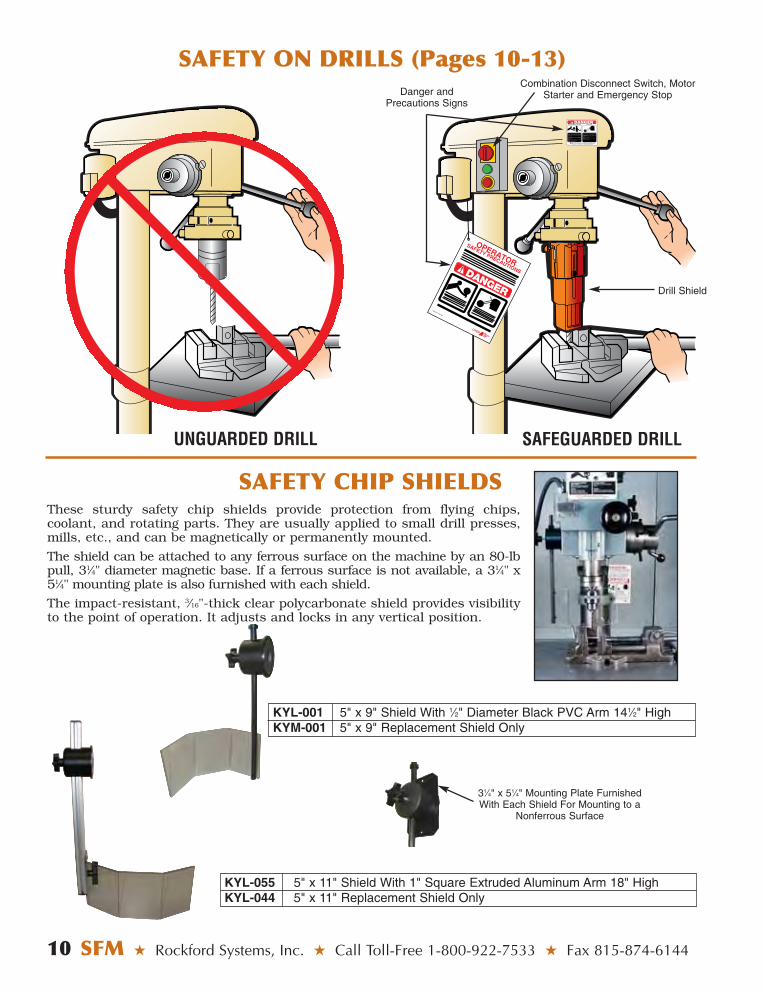
Danger andPrecautions Signs
Drill Shield
Combination Disconnect Switch, MotorStarter and Emergency Stop
UNGUARDED DRILL SAFEGUARDED DRILL
These sturdy safety chip shields provide protection from flying chips,coolant, and rotating parts. They are usually applied to small drill presses,mills, etc., and can be magnetically or permanently mounted.
The shield can be attached to any ferrous surface on the machine by an 80-lbpull, 31⁄4" diameter magnetic base. If a ferrous surface is not available, a 31⁄4" x51⁄4" mounting plate is also furnished with each shield.
The impact-resistant, 3⁄16"-thick clear polycarbonate shield provides visibilityto the point of operation. It adjusts and locks in any vertical position.
SAFETY CHIP SHIELDS
SAFETY ON DRILLS (Pages 10-13)
KYL-001 5" x 9" Shield With 1⁄2" Diameter Black PVC Arm 141⁄2" HighKYM-001 5" x 9" Replacement Shield Only
KYL-055 5" x 11" Shield With 1" Square Extruded Aluminum Arm 18" HighKYL-044 5" x 11" Replacement Shield Only
31⁄4" x 51⁄4" Mounting Plate FurnishedWith Each Shield For Mounting to a
Nonferrous Surface
Rockford Systems, Inc. ★ Shop Online at www.rockfordsystems.com ★ SFM 11
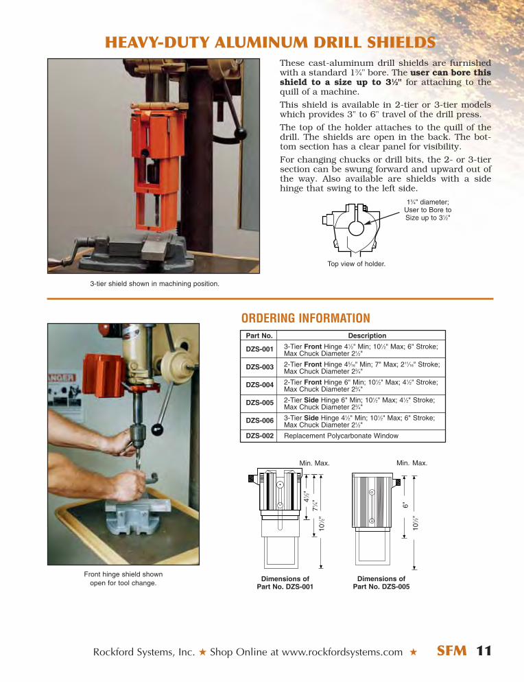
HEAVY-DUTY ALUMINUM DRILL SHIELDS
6"
101 ⁄2
"
Dimensions of Part No. DZS-005
Front hinge shield shown open for tool change.
Min.
101 ⁄2
"
41 ⁄2"
71 ⁄4"
Max.
Dimensions of Part No. DZS-001
Min. Max.
Part No. Description
DZS-001 3-Tier Front Hinge 41⁄2" Min; 101⁄2" Max; 6" Stroke;Max Chuck Diameter 21⁄2"
DZS-003 2-Tier Front Hinge 45⁄16" Min; 7" Max; 211⁄16" Stroke; Max Chuck Diameter 23⁄4"
DZS-004 2-Tier Front Hinge 6" Min; 101⁄2" Max; 41⁄2" Stroke; Max Chuck Diameter 23⁄4"
DZS-005 2-Tier Side Hinge 6" Min; 101⁄2" Max; 41⁄2" Stroke; Max Chuck Diameter 23⁄4"
DZS-006 3-Tier Side Hinge 41⁄2" Min; 101⁄2" Max; 6" Stroke; Max Chuck Diameter 21⁄2"
DZS-002 Replacement Polycarbonate Window
3-tier shield shown in machining position.
ORDERING INFORMATION
13⁄4" diameter; User to Bore toSize up to 31⁄2"
Top view of holder.
These cast-aluminum drill shields are furnishedwith a standard 13⁄4" bore. The user can bore thisshield to a size up to 31⁄2" for attaching to thequill of a machine.
This shield is available in 2-tier or 3-tier modelswhich provides 3" to 6" travel of the drill press.
The top of the holder attaches to the quill of thedrill. The shields are open in the back. The bot-tom section has a clear panel for visibility.
For changing chucks or drill bits, the 2- or 3-tiersection can be swung forward and upward out ofthe way. Also available are shields with a sidehinge that swing to the left side.
12 SFM ★ Rockford Systems, Inc. ★ Call Toll-Free 1-800-922-7533 ★ Fax 815-874-6144
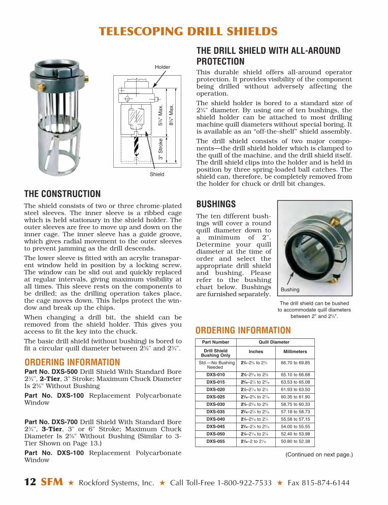
THE CONSTRUCTIONThe shield consists of two or three chrome-platedsteel sleeves. The inner sleeve is a ribbed cagewhich is held stationary in the shield holder. Theouter sleeves are free to move up and down on theinner cage. The inner sleeve has a guide groove,which gives radial movement to the outer sleevesto prevent jamming as the drill descends.
The lower sleeve is fitted with an acrylic transpar-ent window held in position by a locking screw.The window can be slid out and quickly replacedat regular intervals, giving maximum visibility atall times. This sleeve rests on the components tobe drilled; as the drilling operation takes place,the cage moves down. This helps protect the win-dow and break up the chips.
When changing a drill bit, the shield can beremoved from the shield holder. This gives youaccess to fit the key into the chuck.
The basic drill shield (without bushing) is bored tofit a circular quill diameter between 25⁄8" and 23⁄4".
ORDERING INFORMATIONPart No. DXS-500 Drill Shield With Standard Bore23⁄4", 2-Tier, 3" Stroke; Maximum Chuck DiameterIs 25⁄8" Without Bushing
Part No. DXS-100 Replacement PolycarbonateWindow
Part No. DXS-700 Drill Shield With Standard Bore23⁄4", 3-Tier, 3" or 6" Stroke; Maximum ChuckDiameter Is 25⁄8" Without Bushing (Similar to 3-Tier Shown on Page 13.)
Part No. DXS-100 Replacement PolycarbonateWindow
BUSHINGSThe ten different bush-ings will cover a roundquill diameter down toa minimum of 2".Determine your quilldiameter at the time oforder and select theappropriate drill shieldand bushing. Pleaserefer to the bushingchart below. Bushingsare furnished separately.
The drill shield can be bushed to accommodate quill diameters
between 2" and 25⁄8".
Part Number Quill Diameter
Drill ShieldBushing Only
Std.—No Bushing 23⁄4–25⁄8 to 23⁄4 66.70 to 69.85Needed
DXS-010 25⁄8–29⁄16 to 25⁄8 65.10 to 66.68
DXS-015 29⁄16–21⁄2 to 29⁄16 63.53 to 65.08
DXS-020 21⁄2–27⁄16 to 21⁄2 61.93 to 63.50
DXS-025 27⁄16–23⁄8 to 27⁄16 60.35 to 61.90
DXS-030 23⁄8–25⁄16 to 23⁄8 58.75 to 60.33
DXS-035 25⁄16–21⁄4 to 25⁄16 57.18 to 58.73
DXS-040 21⁄4–23⁄16 to 21⁄4 55.58 to 57.15
DXS-045 23⁄16–21⁄8 to 23⁄16 54.00 to 55.55
DXS-050 21⁄8–21⁄16 to 21⁄8 52.40 to 53.98
DXS-055 21⁄16–2 to 21⁄16 50.80 to 52.38
Inches Millimeters
Bushing
ORDERING INFORMATION
TELESCOPING DRILL SHIELDS
THE DRILL SHIELD WITH ALL-AROUNDPROTECTIONThis durable shield offers all-around operatorprotection. It provides visibility of the componentbeing drilled without adversely affecting theoperation.
The shield holder is bored to a standard size of 23⁄4" diameter. By using one of ten bushings, theshield holder can be attached to most drillingmachine quill diameters without special boring. Itis available as an “off-the-shelf” shield assembly.
The drill shield consists of two major compo-nents—the drill shield holder which is clamped tothe quill of the machine, and the drill shield itself.The drill shield clips into the holder and is held inposition by three spring-loaded ball catches. Theshield can, therefore, be completely removed fromthe holder for chuck or drill bit changes.
Holder
53 ⁄8"
Max
.
Shield
3"S
trok
e
83 ⁄8"
Max
.
(Continued on next page.)

TELESCOPING DRILL SHIELDS
Rockford Systems, Inc. ★ Shop Online at www.rockfordsystems.com ★ SFM 13
3-TIER DRILL SHIELD FOR IRREGULAR-SHAPED QUILLSThis drill shield has the same three-lug mounting as illustrated above. It has a 3"bore and will fit a maximum chuck diameter of 25⁄8". This shield allows 3" or 6"travel of the chuck and drill bit.
When the 3-tier drill shield is in the position shown here, it has an overall lengthof 111⁄2". When the thumbscrew is adjusted to the middle or top holes, the overalllength is 10" and 81⁄2" respectively. When the thumbscrew is in a retracted position(not in the bottom hole of top tier), the bottom two tiers will move up and down toprovide 6" of travel. When the thumbscrew is engaged into one of the three holes,only the bottom tier will travel allowing a 3" stroke.
ORDERING INFORMATIONPart No. DXS-800 3-Tier Drill Shield, 3" or 6" Stroke
Part No. DXS-100 Replacement Polycarbonate Window
When the quill of a drill press is not round, but anirregular shape (pear shape in some cases), the three-lug drill shield is ideal. The photo illustrates how thethree-lug shield is applied.
If the drill shields offered in this catalog will notmount to your machine, please send us a photo anddimensions of the quill size. We would be pleased tosend you a proposal on a special quill holder.
This drill shield is for drill presses that have 3" to 33⁄4"quills. It has three-lug mounting and fits drill presseswith a 3" stroke and a maximum chuck diameter of 25⁄8".
Lug
Standard bore 3"; customercan bore up to 33⁄4".
ORDERING INFORMATIONPart No. DXS-600 2-Tier Drill Shield, 3" Stroke
Part No. DXS-100 Replacement Polycarbonate Window
Part No. For LFA® Chuck Model No. For Jacobs Chuck Model No. Pilot Size
SLK-001 N/A 0, 0B 1⁄8"
SLK-002 81-1A, 81-1B 1A, 1B, 1BS, MC1 5⁄32"
SLK-003 81-4B 7, 7-1A, 7B 7⁄32"
SLK-004 81b-13A, 81b-13B, 42-13B, 81bS-13A 30, 30-1A, 30B, 31B, 31BA, 81/2N, MC4 15⁄64"
SLK-005 82-2A, 82-2B 2A, 2B, MC5 1⁄4"
SLK-006 82A-5A, 43b-5A, 82A-5B, 43b-5B, 11N, 32, 32B, 33, 33B, 33BA, 33F, 1⁄4"82AS-5A, 43BZ-5B 33KD, 3326A, MC-10, MC33
DC1G61, DC1G61AD, DC4G61,DC4G61AD, SLK-007 4200-B1, 412-B1, 420-B1 H1G61, MC2, MC1G41, MC1G60, MC1G61, 1⁄4"
MC1G75, U4G41, U4G60, U4G61
DC8K33, DC8K61, DK8K64, H8K33, H8K61, H8K64,SLK-008 422-B13, 4220-B13 MC4K01, MC4K41, MC4K61, MC8K26, MC8K64, 9⁄32"
MC8K64AD, U8K33, U8K33A, U8K64, U8K64A, U8K61
SLK-009 43-6A, 43-6B, 84-6A, 45-6A, 84-6B, 3, 3A, 3AE, 3B, 3KD, 3PD, 6AE, 6A-2A, 6A-33, 6B, 14N, 5⁄16"45-6B, 83S-6A, 84S-6A, 44Z-6B, 43SB-6A 34, 34B, 34KD, 34PD, 55B, 56B, 58B, 75A, 634, 634B
SLK-010 85-9A, 85B-9A, 85S-9A, 85BS-9A 16N, 18BN, 36, 36B, 37KD, 37PD, 59B 3⁄8"
SLK-011 N/A 20N 7⁄16"
Thumbscrew
3"
Setscrews Inside Lugs
41⁄4"
2-TIER DRILL SHIELD FOR IRREGULAR-SHAPED QUILLS
SPRING-LOADED/SELF-EJECTING CHUCK KEYS FOR DRILL PRESSESORDERING INFORMATION
SAFETY ON LATHES (Pages 14-22)
14 SFM ★ Rockford Systems, Inc. ★ Call Toll-Free 1-800-922-7533 ★ Fax 815-874-6144
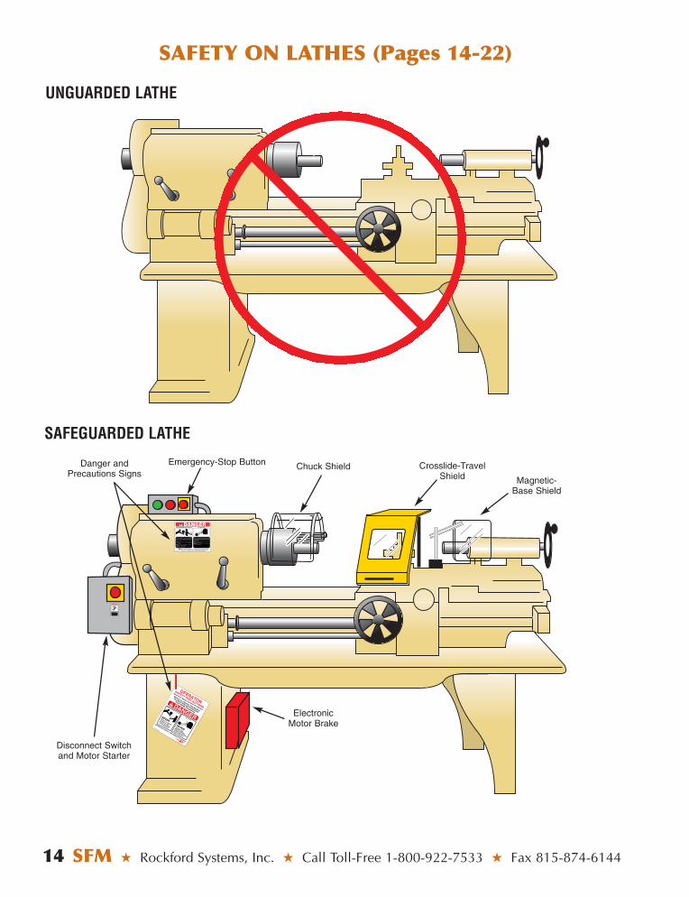
UNGUARDED LATHE
SAFEGUARDED LATHE
ROTATING MEMBERS AND TOOLS
Part No. KSC-046
ALWAYS wear proper personal protective equipment when operating this machine.This sign does not cover all dangers that could happen while operating this machine.
Do Not Remove or Cover This Sign – See Back For Mounting Instructions
You are exposed to moving machine parts that can crush, dismember and cause death.
DO NOT operate this machine without shield(s) in place.
NEVER place your fingers, hands or any part of
your body on or near the rotating parts of this machine.
NEVER operate this machine with loose clothing, jewelry, or unrestrained long hair.
FAILURE to obey will result in loss of fingers or limbs, or could cause death.
FLYING PARTS
You are exposed to moving machine parts that can cause eye or bodily injury dueto hazardous flying chips, sparks, andcoolant splash.
NEVER operate this machinery without proper eye and body protection.
FAILURE to obey will result in eye injury or severe personal injury.
Can cause serious injury or death if hand or any part of body is placed in this electrical enclosure.
Turn off main power and lock out the disconnect switch before opening this electrical enclosure.
DO NOT REMOVE OR COVER THIS SIGNKST-152
WARNING
Chuck ShieldEmergency-Stop ButtonDanger andPrecautions Signs
Disconnect Switchand Motor Starter
Crosslide-TravelShield Magnetic-
Base Shield
ElectronicMotor Brake
SLIDING LATHE SHIELDS
Rockford Systems, Inc. ★ Shop Online at www.rockfordsystems.com ★ SFM 15
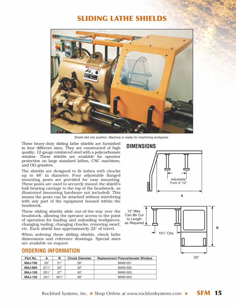
These heavy-duty sliding lathe shields are furnishedin four different sizes. They are constructed of highquality, 12-gauge reinforced steel with a polycarbonatewindow. These shields are available for operator protection on large standard lathes, CNC machines,and OD grinders.
The shields are designed to fit lathes with chucksup to 48" in diameter. Four adjustable flangedmounting posts are provided for easy mounting.These posts are used to securely mount the shield’sball-bearing carriage to the top of the headstock, as illustrated (mounting hardware not included). Thismeans the posts can be attached without interferingwith any part of the equipment housed within theheadstock.
These sliding shields slide out-of-the-way over theheadstock, allowing the operator access to the pointof operation for loading and unloading workpieces,changing tooling, changing chucks, removing swarf,etc. Each shield has approximately 22" of travel.
When ordering these sliding shields, check lathedimensions and reference drawings. Special sizesare available on request.
ORDERING INFORMATION
AdjustableFrom 2"-12"
A
20"
B
153⁄4" Ctrs.
12" Max.Can Be Cutto Length
as Required
Shield slid into position. Machine is ready for machining workpiece.
DIMENSIONS
Part No. A B Chuck Diameter Replacement Polycarbonate Window
MAJ-700 26" 21" 28" MAW-001
MAJ-800 271⁄4" 23" 32" MAW-002
MAJ-100 291⁄2" 27" 40" MAW-003
MAJ-120 331⁄4" 303⁄4" 48" MAW-004
CROSSLIDE-TRAVEL LATHE SHIELDS
16 SFM ★ Rockford Systems, Inc. ★ Call Toll-Free 1-800-922-7533 ★ Fax 815-874-6144
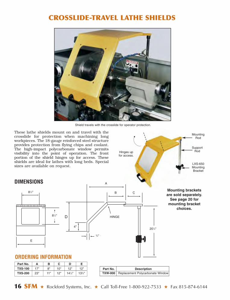
Part No. A B C D E
TXS-100 17" 8" 10" 12" 12"
TXS-200 23" 11" 12" 141⁄2" 133⁄4"
E
A
4"
D
CB
HINGE
SupportRod
MountingRod
LXS-650MountingBracket
Mounting bracketsare sold separately.
See page 20 formounting bracket
choices.
Hinges upfor access.
These lathe shields mount on and travel with thecrosslide for protection when machining longworkpieces. The 18-gauge reinforced steel structureprovides protection from flying chips and coolant.The high-impact polycarbonate window permits visibility into the point of operation. The front portion of the shield hinges up for access. Theseshields are ideal for lathes with long beds. Specialsizes are available on request.
Shield travels with the crosslide for operator protection.
DIMENSIONS
81⁄2"
201⁄4"
3⁄4"
81⁄2"
E
4"
A
B
HINGE
C
ORDERING INFORMATION
Part No. DescriptionTXW-000 Replacement Polycarbonate Window
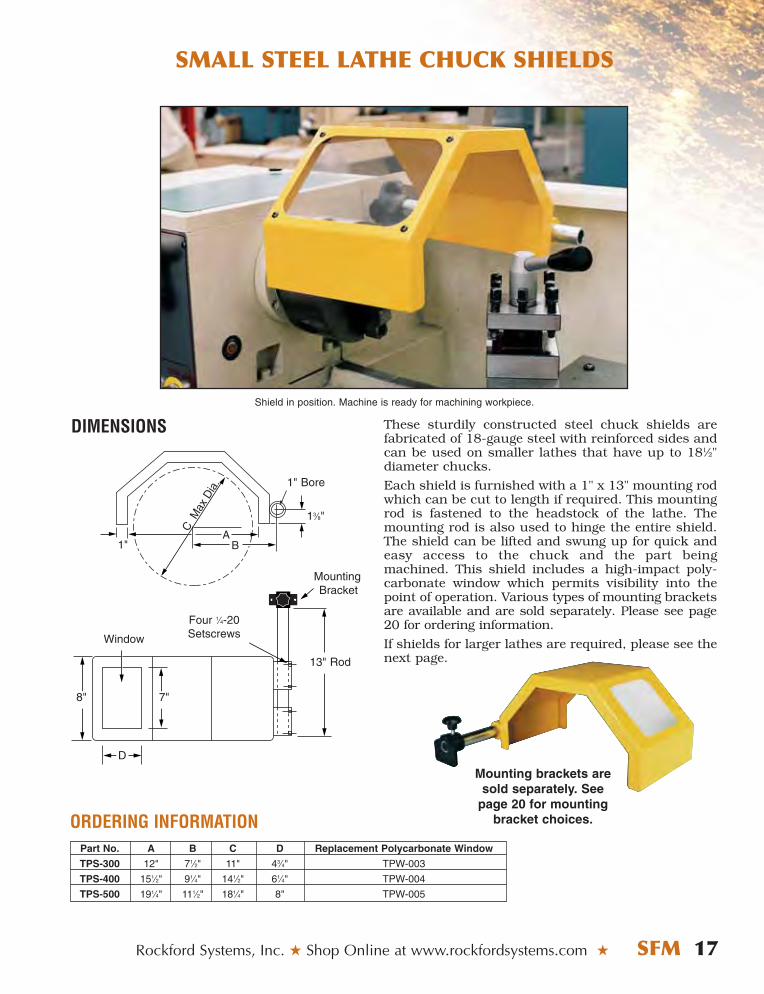
These sturdily constructed steel chuck shields arefabricated of 18-gauge steel with reinforced sides andcan be used on smaller lathes that have up to 181⁄2"diameter chucks.
Each shield is furnished with a 1" x 13" mounting rodwhich can be cut to length if required. This mountingrod is fastened to the headstock of the lathe. Themounting rod is also used to hinge the entire shield.The shield can be lifted and swung up for quick andeasy access to the chuck and the part beingmachined. This shield includes a high-impact poly-carbonate window which permits visibility into thepoint of operation. Various types of mounting bracketsare available and are sold separately. Please see page20 for ordering information.
If shields for larger lathes are required, please see thenext page.
SMALL STEEL LATHE CHUCK SHIELDS
Rockford Systems, Inc. ★ Shop Online at www.rockfordsystems.com ★ SFM 17
ORDERING INFORMATION
DIMENSIONSShield in position. Machine is ready for machining workpiece.
Four 1⁄4-20SetscrewsWindow
13" Rod
1" Bore
13⁄8"
Mounting
D
8" 7"
Bracket
Part No. A B C D Replacement Polycarbonate Window
TPS-300 12" 71⁄2" 11" 43⁄4" TPW-003
TPS-400 151⁄2" 91⁄4" 141⁄2" 61⁄4" TPW-004
TPS-500 191⁄4" 111⁄2" 181⁄4" 8" TPW-005
Mounting brackets aresold separately. See
page 20 for mountingbracket choices.
LARGE STEEL LATHE CHUCK SHIELDS
18 SFM ★ Rockford Systems, Inc. ★ Call Toll-Free 1-800-922-7533 ★ Fax 815-874-6144
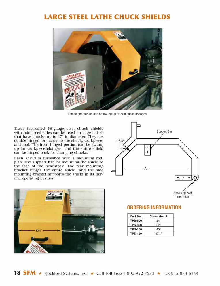
These fabricated 18-gauge steel chuck shieldswith reinforced sides can be used on large lathesthat have chucks up to 47" in diameter. They aredouble hinged for access to the chuck, workpiece,and tool. The front hinged portion can be swungup for workpiece changes, and the entire shieldcan be hinged back for changing chucks.
Each shield is furnished with a mounting rod,plate and support bar for mounting the shield tothe face of the headstock. The rear mountingbracket hinges the entire shield, and the sidemounting bracket supports the shield in its nor-mal operating position.
A
Mounting Rodand Plate
Hinge
Support Bar
133⁄4"
The hinged portion can be swung up for workpiece changes.
ORDERING INFORMATIONPart No. Dimension A
TPS-600 24"
TPS-800 32"
TPS-100 40"
TPS-120 471⁄2"
TRANSPARENT LATHE CHUCK SHIELDS
Rockford Systems, Inc. ★ Shop Online at www.rockfordsystems.com ★ SFM 19
Optional MountingBracket With Electrical
Safety Interlock
High-Impact-Resistant ClearPolycarbonate
Swings up forAccess
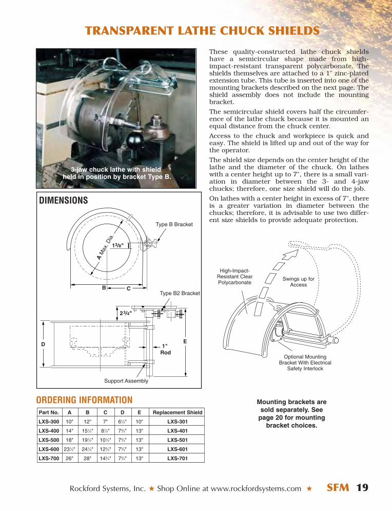
3-jaw chuck lathe with shieldheld in position by bracket Type B.
These quality-constructed lathe chuck shieldshave a semicircular shape made from high-impact-resistant transparent polycarbonate. Theshields themselves are attached to a 1" zinc-platedextension tube. This tube is inserted into one of themounting brackets described on the next page. Theshield assembly does not include the mountingbracket.
The semicircular shield covers half the circumfer-ence of the lathe chuck because it is mounted anequal distance from the chuck center.
Access to the chuck and workpiece is quick andeasy. The shield is lifted up and out of the way forthe operator.
The shield size depends on the center height of thelathe and the diameter of the chuck. On latheswith a center height up to 7", there is a small vari-ation in diameter between the 3- and 4-jawchucks; therefore, one size shield will do the job.
On lathes with a center height in excess of 7", thereis a greater variation in diameter between thechucks; therefore, it is advisable to use two differ-ent size shields to provide adequate protection.
Part No. A B C D E Replacement Shield
LXS-300 10" 12" 7" 61⁄2" 10" LXS-301
LXS-400 14" 151⁄2" 81⁄2" 73⁄4" 13" LXS-401
LXS-500 18" 191⁄2" 101⁄2" 73⁄4" 13" LXS-501
LXS-600 231⁄2" 241⁄4" 123⁄4" 73⁄4" 13" LXS-601
LXS-700 26" 28" 143⁄4" 73⁄4" 13" LXS-701
ORDERING INFORMATION
B
AM
ax. D
ia.
C
Type B Bracket
D E
Type B2 Bracket
1" Rod
Support Assembly
DIMENSIONS
Mounting brackets aresold separately. See
page 20 for mountingbracket choices.
MOUNTING BRACKETS FOR SMALL STEEL AND TRANSPARENT LATHE CHUCK SHIELDS
20 SFM ★ Rockford Systems, Inc. ★ Call Toll-Free 1-800-922-7533 ★ Fax 815-874-6144
The small steel (page 17) and transparent (page19) lathe chuck shields can be interlocked to themotor starter. When the chuck shield is lifted up,the contact on the switch is opened. This causesthe machine to stop. The switch is attached to aheavy-duty mounting bracket.
Part number FKT-781 interlocking bracketassembly shown below includes mountingbracket LXS-652.
The zinc-plated extension tube, to which the polycar-bonate and steel shields are fastened, is mounted tothe headstock of the lathe by a mounting bracket.
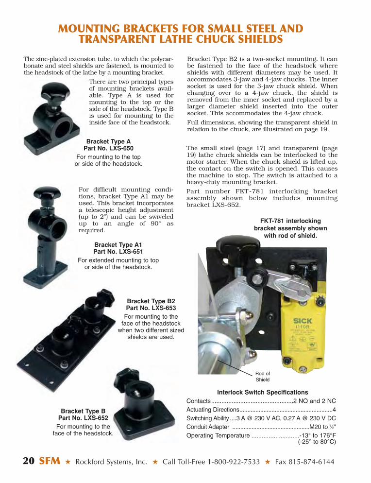
There are two principal typesof mounting brackets avail-able. Type A is used formounting to the top or theside of the headstock. Type Bis used for mounting to theinside face of the headstock.
For difficult mounting condi-tions, bracket Type A1 may beused. This bracket incorporatesa telescopic height adjustment(up to 2") and can be swiveledup to an angle of 90° asrequired.
Bracket Type APart No. LXS-650
For mounting to the topor side of the headstock.
Bracket Type B2 is a two-socket mounting. It canbe fastened to the face of the headstock whereshields with different diameters may be used. Itaccommodates 3-jaw and 4-jaw chucks. The innersocket is used for the 3-jaw chuck shield. Whenchanging over to a 4-jaw chuck, the shield isremoved from the inner socket and replaced by alarger diameter shield inserted into the outersocket. This accommodates the 4-jaw chuck.
Full dimensions, showing the transparent shield inrelation to the chuck, are illustrated on page 19.
Bracket Type A1Part No. LXS-651
For extended mounting to topor side of the headstock.
Bracket Type BPart No. LXS-652
For mounting to theface of the headstock.
Bracket Type B2Part No. LXS-653
For mounting to theface of the headstock
when two different sizedshields are used.
FKT-781 interlockingbracket assembly shown
with rod of shield.
Rod ofShield
Interlock Switch SpecificationsContacts................................................2 NO and 2 NCActuating Directions..........................................................4Switching Ability ....3 A @ 230 V AC, 0.27 A @ 230 V DCConduit Adapter ................................................M20 to 1⁄2"Operating Temperature ............................-13° to 176°F
(-25° to 80°C)
STANDARD SIZE LATHE CHUCK WRENCHES
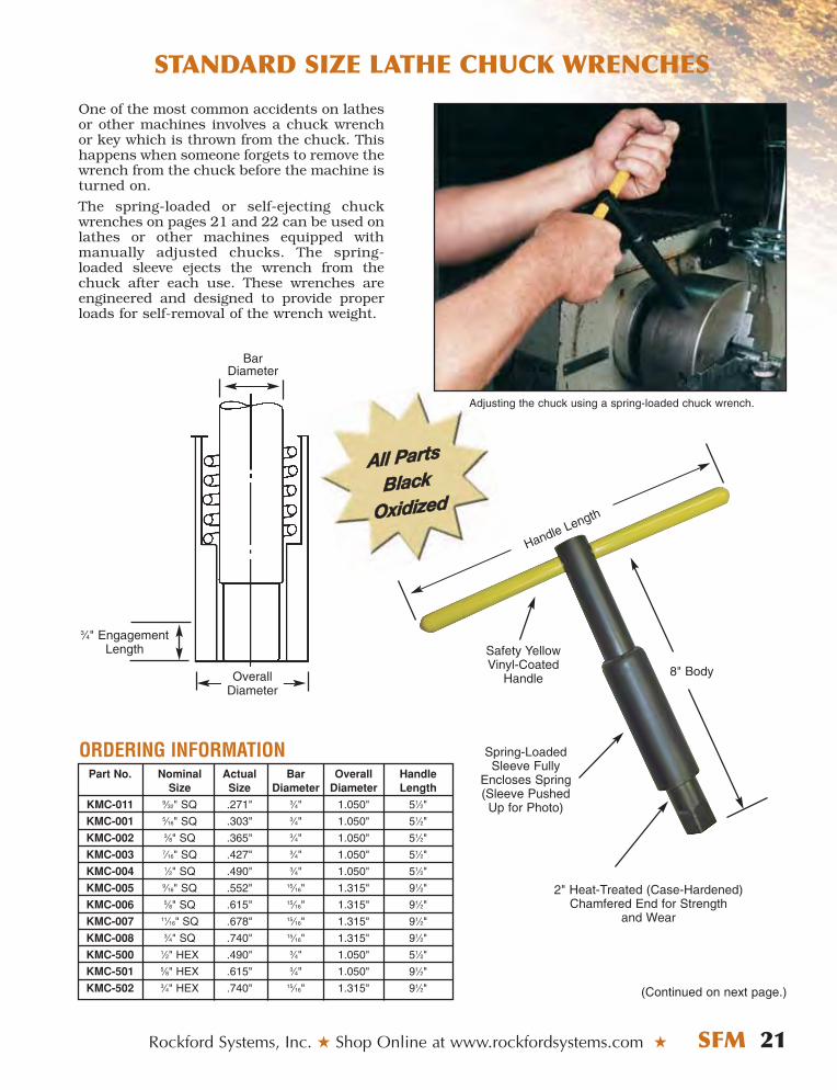
One of the most common accidents on lathesor other machines involves a chuck wrenchor key which is thrown from the chuck. Thishappens when someone forgets to remove thewrench from the chuck before the machine isturned on.
The spring-loaded or self-ejecting chuckwrenches on pages 21 and 22 can be used onlathes or other machines equipped withmanually adjusted chucks. The spring-loaded sleeve ejects the wrench from thechuck after each use. These wrenches areengineered and designed to provide properloads for self-removal of the wrench weight.
Rockford Systems, Inc. ★ Shop Online at www.rockfordsystems.com ★ SFM 21
ORDERING INFORMATIONPart No. Nominal Actual Bar Overall Handle
Size Size Diameter Diameter Length
KMC-011 9⁄32" SQ .271" 3⁄4" 1.050" 51⁄2"
KMC-001 5⁄16" SQ .303" 3⁄4" 1.050" 51⁄2"
KMC-002 3⁄8" SQ .365" 3⁄4" 1.050" 51⁄2"
KMC-003 7⁄16" SQ .427" 3⁄4" 1.050" 51⁄2"
KMC-004 1⁄2" SQ .490" 3⁄4" 1.050" 51⁄2"
KMC-005 9⁄16" SQ .552" 15⁄16" 1.315" 91⁄2"
KMC-006 5⁄8" SQ .615" 15⁄16" 1.315" 91⁄2"
KMC-007 11⁄16" SQ .678" 15⁄16" 1.315" 91⁄2"
KMC-008 3⁄4" SQ .740" 15⁄16" 1.315" 91⁄2"
KMC-500 1⁄2" HEX .490" 3⁄4" 1.050" 51⁄2"
KMC-501 5⁄8" HEX .615" 3⁄4" 1.050" 91⁄2"
KMC-502 3⁄4" HEX .740" 15⁄16" 1.315" 91⁄2"
OverallDiameter
BarDiameter
2" Heat-Treated (Case-Hardened)Chamfered End for Strength
and Wear
Handle Length
Spring-LoadedSleeve Fully
Encloses Spring (Sleeve PushedUp for Photo)
8" Body
Safety YellowVinyl-Coated
Handle
3⁄4" EngagementLength
(Continued on next page.)
AAllll PPaarrttss
BBllaacckk
OOxxiiddiizzeedd
Adjusting the chuck using a spring-loaded chuck wrench.

22 SFM ★ Rockford Systems, Inc. ★ Call Toll-Free 1-800-922-7533 ★ Fax 815-874-6144
LONGER LATHE CHUCK WRENCHES
LONGER BBODY, LLONG SSLIDING HHANDLE!
OverallDiameter
BarDiameter
3⁄4" EngagementLength
ThumbScrew
18" Sliding Handle
18" Sliding Handle
Spring-LoadedSleeve Fully
Encloses Spring
10" Body
2" Heat-Treated(Case-Hardened)Chamfered Endfor Strength and
Wear
ORDERING INFORMATIONPart No. Nominal Actual Bar Overall
Size Size Diameter Diameter
KMC-900 9⁄32" SQ .271" 3⁄4" 1.050"
KMC-901 5⁄16" SQ .303" 3⁄4" 1.050"
KMC-902 3⁄8" SQ .365" 3⁄4" 1.050"
KMC-903 7⁄16" SQ .427" 3⁄4" 1.050"
KMC-904 1⁄2" SQ .490" 3⁄4" 1.050"
KMC-905 9⁄16" SQ .552" 15⁄16" 1.315"
KMC-906 5⁄8" SQ .615" 15⁄16" 1.315"
KMC-907 11⁄16" SQ .678" 15⁄16" 1.315"
KMC-908 3⁄4" SQ .740" 15⁄16" 1.315"
KMC-909 1⁄2" HEX .490" 3⁄4" 1.050"
KMC-910 5⁄8" HEX .615" 3⁄4" 1.050"
KMC-911 3⁄4" HEX .740" 15⁄16" 1.315"
AAllll PPaarrttssBBllaacckk
OOxxiiddiizzeedd
The 18" handle can beslid into position and
locked in place with thethumb screw.
Rockford Systems, Inc. ★ Shop Online at www.rockfordsystems.com ★ SFM 23
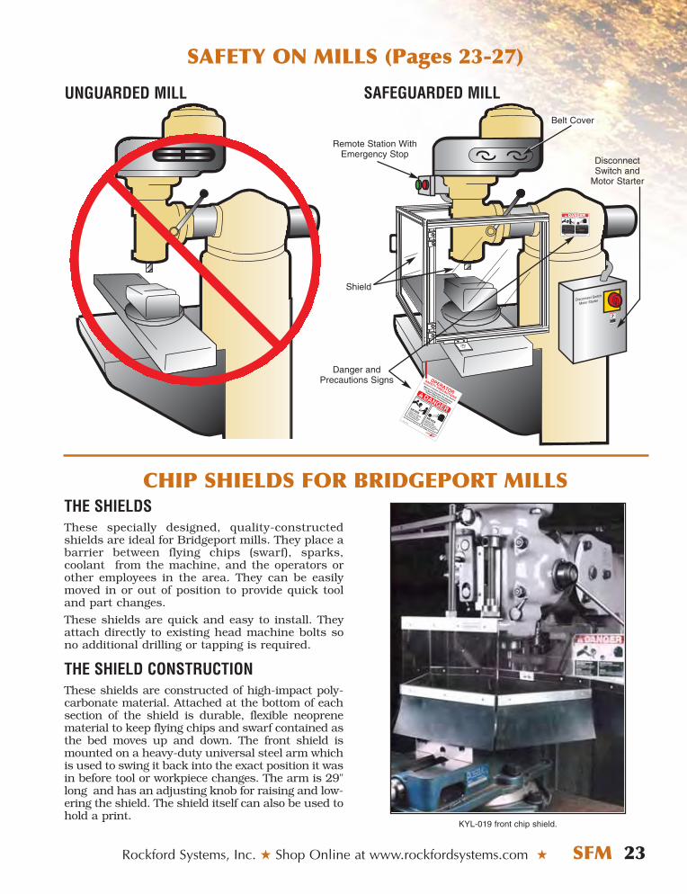
THE SHIELDSThese specially designed, quality-constructedshields are ideal for Bridgeport mills. They place abarrier between flying chips (swarf), sparks,coolant from the machine, and the operators orother employees in the area. They can be easilymoved in or out of position to provide quick tooland part changes.
These shields are quick and easy to install. Theyattach directly to existing head machine bolts sono additional drilling or tapping is required.
THE SHIELD CONSTRUCTIONThese shields are constructed of high-impact poly-carbonate material. Attached at the bottom of eachsection of the shield is durable, flexible neoprenematerial to keep flying chips and swarf contained asthe bed moves up and down. The front shield ismounted on a heavy-duty universal steel arm whichis used to swing it back into the exact position it wasin before tool or workpiece changes. The arm is 29"long and has an adjusting knob for raising and low-ering the shield. The shield itself can also be used tohold a print.
KYL-019 front chip shield.
SAFETY ON MILLS (Pages 23-27)
Disconnect Switch
Motor Starter
Can cause serious injury
or death if hand or any part
of body is placed in this
electrical enclosure.
Turn off main power and
lock out the disconnect
switch before opening this
electrical enclosure.
DO NOT REMOVE OR COVER THIS SIGN
KST-152
WARNING
ROTATING MEMBERS AND TOOLS
Part No. KSC-046
ALWAYS wear proper personal protective equipment when operating this machine.This sign does not cover all dangers that could happen while operating this machine.
Do Not Remove or Cover This Sign – See Back For Mounting Instructions
You are exposed to moving machine parts that can crush, dismember and cause death. DO NOT operate this machine without shield(s) in place. NEVER place your fingers, hands or any part of your body on or near the rotating parts of this machine. NEVER operate this machine with loose clothing, jewelry, or unrestrained long hair.
FAILURE to obey will result in loss of fingers or limbs, or could cause death.
FLYING PARTS
You are exposed to moving machine parts that can cause eye or bodily injury dueto hazardous flying chips, sparks, andcoolant splash.
NEVER operate this machinery without proper eye and body protection. FAILURE to obey will result in eye injury or severe personal injury.
UNGUARDED MILL
CHIP SHIELDS FOR BRIDGEPORT MILLS
SAFEGUARDED MILL
Remote Station WithEmergency Stop
Belt Cover
Danger andPrecautions Signs
DisconnectSwitch and
Motor Starter
Shield
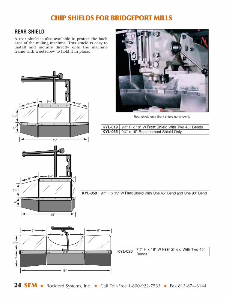
Rear shield only (front shield not shown).
REAR SHIELDA rear shield is also available to protect the backarea of the milling machine. This shield is easy toinstall and mounts directly onto the machineframe with a setscrew to hold it in place.
24 SFM ★ Rockford Systems, Inc. ★ Call Toll-Free 1-800-922-7533 ★ Fax 815-874-6144
CHIP SHIELDS FOR BRIDGEPORT MILLS
KYL-019 91⁄4" H x 19" W Front Shield With Two 45° BendsKYL-065 91⁄4" x 19" Replacement Shield Only
KYL-020 71⁄4" H x 18" W Rear Shield With Two 45°Bends
KYL-059 91⁄4" H x 15" W Front Shield With One 45° Bend and One 90° Bend
91⁄4"9" 9"9"
9"9"91⁄4"
6"
6" 6"
18"
31⁄4"
51⁄4"
51⁄4"
4"
4"
4"
9"
15"
19"
SLIDE AND SWING-ASIDE SHIELDS
Rockford Systems, Inc. ★ Shop Online at www.rockfordsystems.com ★ SFM 25
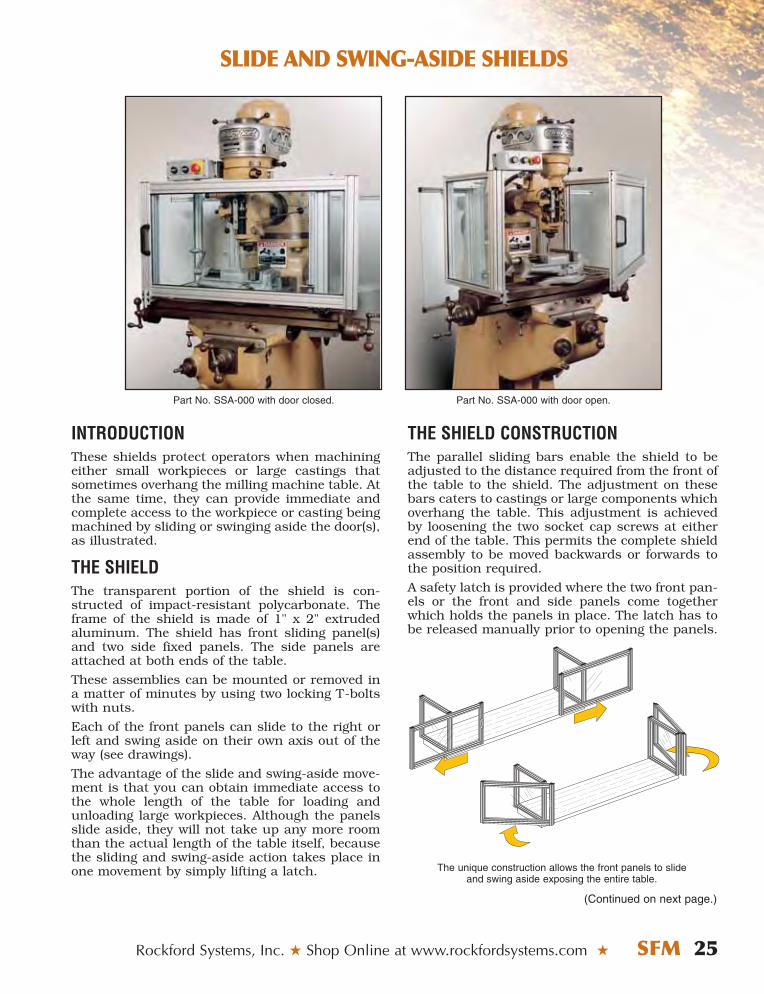
Part No. SSA-000 with door closed. Part No. SSA-000 with door open.
INTRODUCTIONThese shields protect operators when machiningeither small workpieces or large castings thatsometimes overhang the milling machine table. Atthe same time, they can provide immediate andcomplete access to the workpiece or casting beingmachined by sliding or swinging aside the door(s),as illustrated.
THE SHIELDThe transparent portion of the shield is con-structed of impact-resistant polycarbonate. Theframe of the shield is made of 1" x 2" extrudedaluminum. The shield has front sliding panel(s)and two side fixed panels. The side panels areattached at both ends of the table.
These assemblies can be mounted or removed ina matter of minutes by using two locking T-boltswith nuts.
Each of the front panels can slide to the right orleft and swing aside on their own axis out of theway (see drawings).
The advantage of the slide and swing-aside move-ment is that you can obtain immediate access tothe whole length of the table for loading andunloading large workpieces. Although the panelsslide aside, they will not take up any more roomthan the actual length of the table itself, becausethe sliding and swing-aside action takes place inone movement by simply lifting a latch.
THE SHIELD CONSTRUCTIONThe parallel sliding bars enable the shield to beadjusted to the distance required from the front ofthe table to the shield. The adjustment on thesebars caters to castings or large components whichoverhang the table. This adjustment is achievedby loosening the two socket cap screws at eitherend of the table. This permits the complete shieldassembly to be moved backwards or forwards tothe position required.
A safety latch is provided where the two front pan-els or the front and side panels come togetherwhich holds the panels in place. The latch has tobe released manually prior to opening the panels.
(Continued on next page.)
The unique construction allows the front panels to slideand swing aside exposing the entire table.
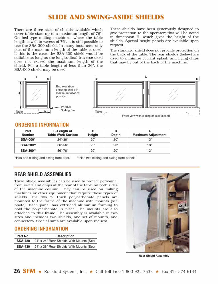
End elevationshowing shield inmaximum forwardposition.
ParallelSliding BarTable TableA
D
H
Front view with sliding shields closed.
Part L–Length of H D ANumber Table Work Surface Height Depth Maximum Adjustment
SSA-000* 24"-36" 20" 20" 13"
SSA-200** 36"-56" 20" 20" 13"
SSA-300** 56"-76" 20" 20" 13"
There are three sizes of shields available whichcover table sizes up to a maximum length of 76".On bed-type milling machines, where the tablelength is well in excess of 76", it is still possible touse the SSA-300 shield. In many instances, onlypart of the maximum length of the table is used.If this is the case, the SSA-300 shield would besuitable as long as the longitudinal traverse useddoes not exceed the maximum length of theshield. For a table length of less than 36", theSSA-000 shield may be used.
L
*Has one sliding and swing front door. **Has two sliding and swing front panels.
These shields have been generously designed togive protection to the operator; this will be notedin dimension H, which gives the height of theshields. Special height panels are available uponrequest.
The standard shield does not provide protection onthe back of the table. The rear shields (below) areused to minimize coolant splash and flying chipsthat may fly out of the back of the machine.
Rear Shield Assembly
ORDERING INFORMATION
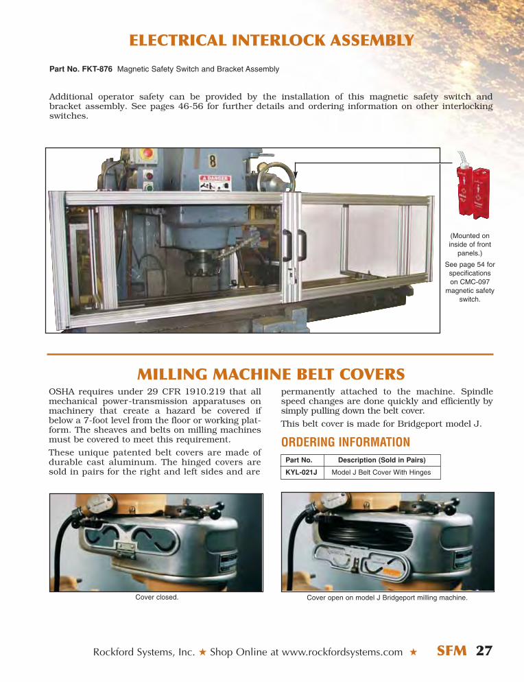
REAR SHIELD ASSEMBLIESThese shield assemblies can be used to protect personnelfrom swarf and chips at the rear of the table on both sidesof the machine column. They can be used on millingmachines or other equipment that require these types ofshields. The two 1⁄4" thick polycarbonate panels aremounted to the frame of the machine with mounts (seephoto). Each panel has extruded aluminum framing tohold the polycarbonate in place. The mounts are alsoattached to this frame. The assembly is available in twosizes and includes two shields, one set of mounts, andconnectors. Special sizes are available upon request.
ORDERING INFORMATIONPart No. DescriptionSSA-420 24" x 24" Rear Shields With Mounts (Set)
SSA-430 24" x 36" Rear Shields With Mounts (Set)
26 SFM ★ Rockford Systems, Inc. ★ Call Toll-Free 1-800-922-7533 ★ Fax 815-874-6144
SLIDE AND SWING-ASIDE SHIELDS
ELECTRICAL INTERLOCK ASSEMBLY
Rockford Systems, Inc. ★ Shop Online at www.rockfordsystems.com ★ SFM 27
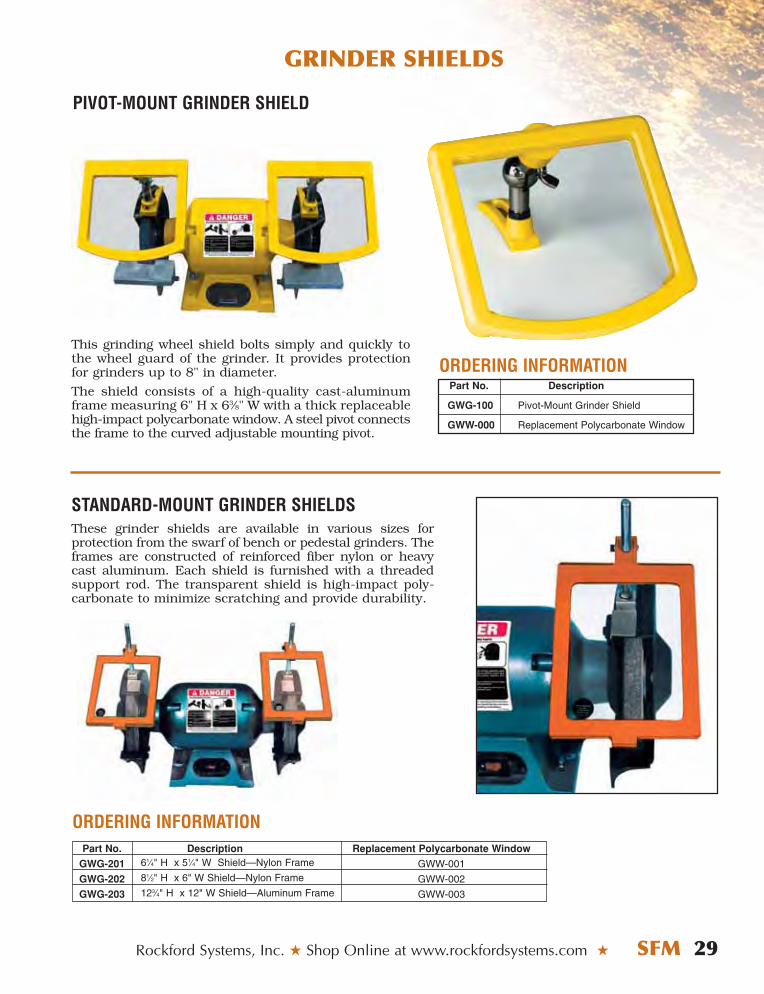
permanently attached to the machine. Spindlespeed changes are done quickly and efficiently bysimply pulling down the belt cover.
This belt cover is made for Bridgeport model J.
ORDERING INFORMATIONPart No. Description (Sold in Pairs)
KYL-021J Model J Belt Cover With Hinges
Cover open on model J Bridgeport milling machine.
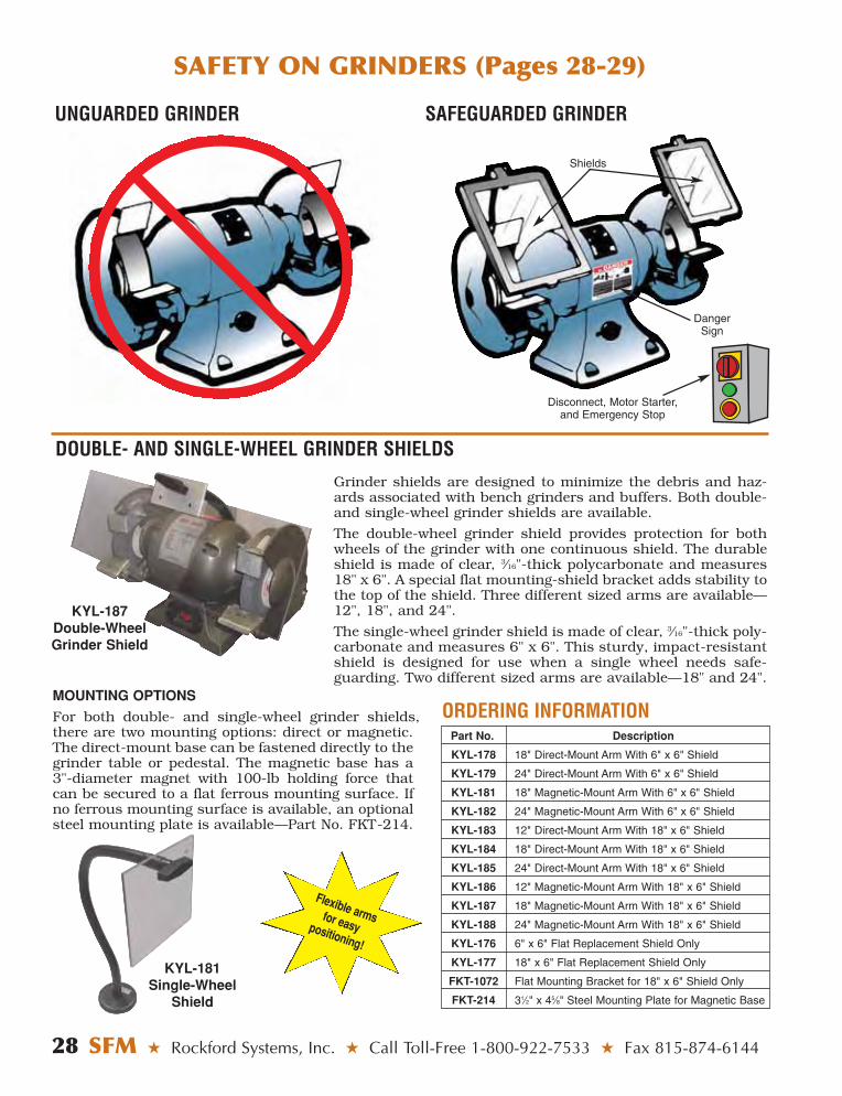
(Mounted oninside of front
panels.)
See page 54 forspecificationson CMC-097
magnetic safetyswitch.
Cover closed.
OSHA requires under 29 CFR 1910.219 that allmechanical power-transmission apparatuses onmachinery that create a hazard be covered ifbelow a 7-foot level from the floor or working plat-form. The sheaves and belts on milling machinesmust be covered to meet this requirement.
These unique patented belt covers are made ofdurable cast aluminum. The hinged covers aresold in pairs for the right and left sides and are
MILLING MACHINE BELT COVERS
Part No. FKT-876 Magnetic Safety Switch and Bracket Assembly
Additional operator safety can be provided by the installation of this magnetic safety switch and bracket assembly. See pages 46-56 for further details and ordering information on other interlockingswitches.
UNGUARDED GRINDER SAFEGUARDED GRINDER
Grinder shields are designed to minimize the debris and haz-ards associated with bench grinders and buffers. Both double-and single-wheel grinder shields are available.
The double-wheel grinder shield provides protection for bothwheels of the grinder with one continuous shield. The durableshield is made of clear, 3⁄16"-thick polycarbonate and measures18" x 6". A special flat mounting-shield bracket adds stability tothe top of the shield. Three different sized arms are available—12", 18", and 24".
The single-wheel grinder shield is made of clear, 3⁄16"-thick poly-carbonate and measures 6" x 6". This sturdy, impact-resistantshield is designed for use when a single wheel needs safe-guarding. Two different sized arms are available—18" and 24".
MOUNTING OPTIONS
For both double- and single-wheel grinder shields,there are two mounting options: direct or magnetic.The direct-mount base can be fastened directly to thegrinder table or pedestal. The magnetic base has a3"-diameter magnet with 100-lb holding force thatcan be secured to a flat ferrous mounting surface. Ifno ferrous mounting surface is available, an optionalsteel mounting plate is available—Part No. FKT-214.
Shields
Danger Sign
Disconnect, Motor Starter, and Emergency Stop
28 SFM ★ Rockford Systems, Inc. ★ Call Toll-Free 1-800-922-7533 ★ Fax 815-874-6144
SAFETY ON GRINDERS (Pages 28-29)
Part No. Description
KYL-178 18" Direct-Mount Arm With 6" x 6" Shield
KYL-179 24" Direct-Mount Arm With 6" x 6" Shield
KYL-181 18" Magnetic-Mount Arm With 6" x 6" Shield
KYL-182 24" Magnetic-Mount Arm With 6" x 6" Shield
KYL-183 12" Direct-Mount Arm With 18" x 6" Shield
KYL-184 18" Direct-Mount Arm With 18" x 6" Shield
KYL-185 24" Direct-Mount Arm With 18" x 6" Shield
KYL-186 12" Magnetic-Mount Arm With 18" x 6" Shield
KYL-187 18" Magnetic-Mount Arm With 18" x 6" Shield
KYL-188 24" Magnetic-Mount Arm With 18" x 6" Shield
KYL-176 6" x 6" Flat Replacement Shield Only
KYL-177 18" x 6" Flat Replacement Shield Only
FKT-1072 Flat Mounting Bracket for 18" x 6" Shield Only
FKT-214 31⁄2" x 45⁄8" Steel Mounting Plate for Magnetic Base
ORDERING INFORMATION
KYL-187Double-WheelGrinder Shield
KYL-181Single-Wheel
Shield
Flexible arms for easy positioning!
DOUBLE- AND SINGLE-WHEEL GRINDER SHIELDS
GRINDER SHIELDS
Rockford Systems, Inc. ★ Shop Online at www.rockfordsystems.com ★ SFM 29
PIVOT-MOUNT GRINDER SHIELD
STANDARD-MOUNT GRINDER SHIELDSThese grinder shields are available in various sizes for protection from the swarf of bench or pedestal grinders. Theframes are constructed of reinforced fiber nylon or heavycast aluminum. Each shield is furnished with a threadedsupport rod. The transparent shield is high-impact poly-carbonate to minimize scratching and provide durability.
This grinding wheel shield bolts simply and quickly tothe wheel guard of the grinder. It provides protectionfor grinders up to 8" in diameter.
The shield consists of a high-quality cast-aluminumframe measuring 6" H x 63⁄8" W with a thick replaceablehigh-impact polycarbonate window. A steel pivot connectsthe frame to the curved adjustable mounting pivot.
ORDERING INFORMATIONPart No. Description
GWG-100 Pivot-Mount Grinder Shield
GWW-000 Replacement Polycarbonate Window
ORDERING INFORMATIONPart No. Description Replacement Polycarbonate Window
GWG-201 61⁄4" H x 51⁄4" W Shield—Nylon Frame GWW-001
GWG-202 81⁄2" H x 6" W Shield—Nylon Frame GWW-002
GWG-203 123⁄4" H x 12" W Shield—Aluminum Frame GWW-003
UNIVERSAL BALL & SOCKET SHIELDS
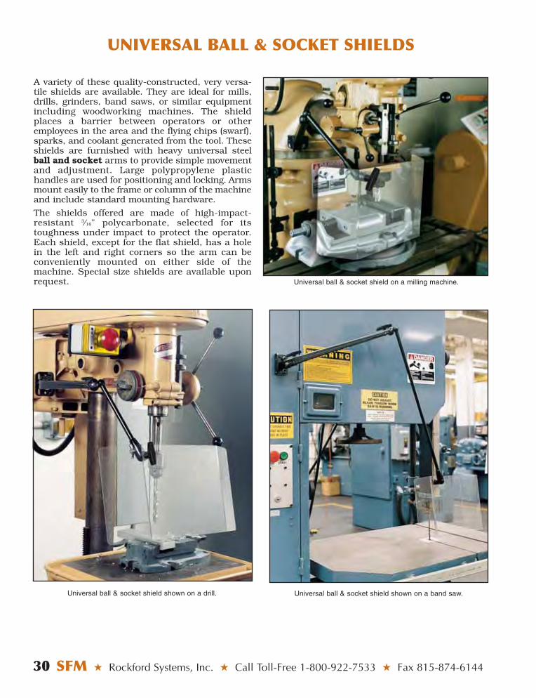
A variety of these quality-constructed, very versa-tile shields are available. They are ideal for mills,drills, grinders, band saws, or similar equipmentincluding woodworking machines. The shieldplaces a barrier between operators or otheremployees in the area and the flying chips (swarf),sparks, and coolant generated from the tool. Theseshields are furnished with heavy universal steelball and socket arms to provide simple movementand adjustment. Large polypropylene plastic handles are used for positioning and locking. Armsmount easily to the frame or column of the machineand include standard mounting hardware.
The shields offered are made of high-impact-resistant 3⁄16" polycarbonate, selected for itstoughness under impact to protect the operator.Each shield, except for the flat shield, has a holein the left and right corners so the arm can beconveniently mounted on either side of themachine. Special size shields are available uponrequest. Universal ball & socket shield on a milling machine.
30 SFM ★ Rockford Systems, Inc. ★ Call Toll-Free 1-800-922-7533 ★ Fax 815-874-6144
Universal ball & socket shield shown on a drill. Universal ball & socket shield shown on a band saw.

UNIVERSAL BALL & SOCKET SHIELDS
(Continued on next page.)
KYL-104 6" x 8" Flat Shield With 21" Universal ArmKYL-105 6" x 8" Flat Shield With 31" Universal ArmKYL-106 6" x 8" Flat Shield With 44" Universal ArmCSAA-3 6" x 8" Flat Replacement Shield OnlyCYF-016 Clamp Kit for Attaching to Table or Ledge
KYL-107 10" x 12" Flat Shield With 21" Universal ArmKYL-108 10" x 12" Flat Shield With 31" Universal ArmKYL-109 10" x 12" Flat Shield With 44" Universal ArmCSAA-5 10" x 12" Flat Replacement Shield OnlyCYF-016 Clamp Kit for Attaching to Table or Ledge
KYL-110 30° Angle Shield (7" Front) With 21" Universal ArmKYL-111 30° Angle Shield (7" Front) With 31" Universal ArmKYL-112 30° Angle Shield (7" Front) With 44" Universal ArmKYL-012 30° Angle (7" Front) Replacement Shield OnlyCYF-016 Clamp Kit for Attaching to Table or Ledge
KYL-113 30° Angle Shield (103⁄8" Front) With 21" Universal ArmKYL-114 30° Angle Shield (103⁄8" Front) With 31" Universal ArmKYL-115 30° Angle Shield (103⁄8" Front) With 44" Universal ArmKYL-017 30° Angle Shield (103⁄8" Front) Replacement Shield OnlyCYF-016 Clamp Kit for Attaching to Table or Ledge
Rockford Systems, Inc. ★ Shop Online at www.rockfordsystems.com ★ SFM 31
All Steel Pivot
Balls Are Hardened
For Longevity
32 SFM ★ Rockford Systems, Inc. ★ Call Toll-Free 1-800-922-7533 ★ Fax 815-874-6144
UNIVERSAL BALL & SOCKET SHIELDS
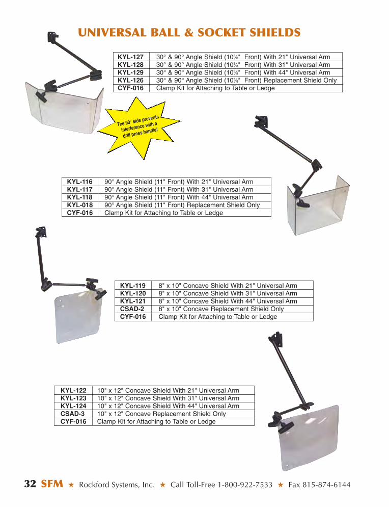
KYL-116 90° Angle Shield (11" Front) With 21" Universal ArmKYL-117 90° Angle Shield (11" Front) With 31" Universal ArmKYL-118 90° Angle Shield (11" Front) With 44" Universal ArmKYL-018 90° Angle Shield (11" Front) Replacement Shield OnlyCYF-016 Clamp Kit for Attaching to Table or Ledge
KYL-119 8" x 10" Concave Shield With 21" Universal ArmKYL-120 8" x 10" Concave Shield With 31" Universal ArmKYL-121 8" x 10" Concave Shield With 44" Universal ArmCSAD-2 8" x 10" Concave Replacement Shield OnlyCYF-016 Clamp Kit for Attaching to Table or Ledge
KYL-122 10" x 12" Concave Shield With 21" Universal ArmKYL-123 10" x 12" Concave Shield With 31" Universal ArmKYL-124 10" x 12" Concave Shield With 44" Universal ArmCSAD-3 10" x 12" Concave Replacement Shield OnlyCYF-016 Clamp Kit for Attaching to Table or Ledge
KYL-127 30° & 90° Angle Shield (103⁄8" Front) With 21" Universal ArmKYL-128 30° & 90° Angle Shield (103⁄8" Front) With 31" Universal ArmKYL-129 30° & 90° Angle Shield (103⁄8" Front) With 44" Universal ArmKYL-126 30° & 90° Angle Shield (103⁄8" Front) Replacement Shield OnlyCYF-016 Clamp Kit for Attaching to Table or Ledge
The 90° side prevents
interference with a
drill press handle!

MAGNETIC-BASE SHIELDS
These rugged magnetic-base shields can be used on lathes, small milling machines, drills, grinders, bandsaws, etc. These shields can be attached to any ferrous surface on the machine by an 80-lb pull magneticbase. If a ferrous surface is not available, a mounting plate (31⁄2" x 45⁄8") is also furnished. Large polypropy-lene plastic handles are used for easy positioning and locking.
The transparent portion of the chip shield is constructed of high-impact-resistant, 3⁄16"-thick clear polycar-bonate material. It is furnished with a circular base which measures 31⁄4" in diameter. An 8" aluminum baseextrusion is provided and attaches to the magnetic base. Also available is a 12" extruded-aluminum armextension. This arm can be cut to a shorter length if required for your application.
Magnetic-base flat shield shown on a lathe. Magnetic-base concave shield shown on a lathe.
Rockford Systems, Inc. ★ Shop Online at www.rockfordsystems.com ★ SFM 33
Part No. Description Replacement Shield OnlyCBS-1C1 Base With 6" x 8" Flat Shield CSAA-3CBS-2C1 Base With 10" x 12" Flat Shield CSAA-5CBS-3C1 Base With 14" x 16" Flat Shield CSAA-7
Part No. Description Replacement Shield OnlyCBS-1C1B 6" x 8" Flat Shield With 12" Arm Extension CSAA-3CBS-2C1B 10" x 12" Flat Shield With 12" Arm Extension CSAA-5CBS-3C1B 14" x 16" Flat Shield With 12" Arm Extension CSAA-7
Part No. Description Replacement Shield OnlyCBS-6C1 Base With 8" x 10" Concave Shield CSAD-2CBS-7C1 Base With 10" x 12" Concave Shield CSAD-3
Part No. Description Replacement Shield OnlyCBS-6C1B 8" x 10" Concave Shield With 12" Arm Extension CSAD-2CBS-7C1B 10" x 12" Concave Shield With 12" Arm Extension CSAD-3
34 SFM ★ Rockford Systems, Inc. ★ Call Toll-Free 1-800-922-7533 ★ Fax 815-874-6144
FLEXIBLE-ARM/SNAKE-ARM/GOOSENECK SHIELDS
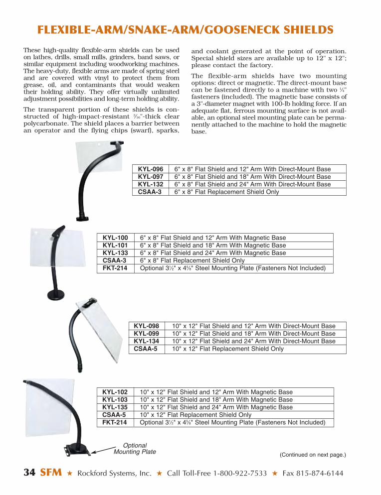
These high-quality flexible-arm shields can be usedon lathes, drills, small mills, grinders, band saws, orsimilar equipment including woodworking machines.The heavy-duty, flexible arms are made of spring steeland are covered with vinyl to protect them fromgrease, oil, and contaminants that would weakentheir holding ability. They offer virtually unlimitedadjustment possibilities and long-term holding ability.
The transparent portion of these shields is con-structed of high-impact-resistant 3⁄16"-thick clearpolycarbonate. The shield places a barrier betweenan operator and the flying chips (swarf), sparks,
KYL-096 6" x 8" Flat Shield and 12" Arm With Direct-Mount BaseKYL-097 6" x 8" Flat Shield and 18" Arm With Direct-Mount BaseKYL-132 6" x 8" Flat Shield and 24" Arm With Direct-Mount BaseCSAA-3 6" x 8" Flat Replacement Shield Only
and coolant generated at the point of operation.Special shield sizes are available up to 12" x 12";please contact the factory.
The flexible-arm shields have two mountingoptions: direct or magnetic. The direct-mount basecan be fastened directly to a machine with two 1⁄4"fasteners (included). The magnetic base consists ofa 3"-diameter magnet with 100-lb holding force. If anadequate flat, ferrous mounting surface is not avail-able, an optional steel mounting plate can be perma-nently attached to the machine to hold the magneticbase.
KYL-098 10" x 12" Flat Shield and 12" Arm With Direct-Mount BaseKYL-099 10" x 12" Flat Shield and 18" Arm With Direct-Mount BaseKYL-134 10" x 12" Flat Shield and 24" Arm With Direct-Mount BaseCSAA-5 10" x 12" Flat Replacement Shield Only
KYL-100 6" x 8" Flat Shield and 12" Arm With Magnetic BaseKYL-101 6" x 8" Flat Shield and 18" Arm With Magnetic BaseKYL-133 6" x 8" Flat Shield and 24" Arm With Magnetic BaseCSAA-3 6" x 8" Flat Replacement Shield OnlyFKT-214 Optional 31⁄2" x 45⁄8" Steel Mounting Plate (Fasteners Not Included)
KYL-102 10" x 12" Flat Shield and 12" Arm With Magnetic BaseKYL-103 10" x 12" Flat Shield and 18" Arm With Magnetic BaseKYL-135 10" x 12" Flat Shield and 24" Arm With Magnetic BaseCSAA-5 10" x 12" Flat Replacement Shield OnlyFKT-214 Optional 31⁄2" x 45⁄8" Steel Mounting Plate (Fasteners Not Included)
OptionalMounting Plate (Continued on next page.)
FLEXIBLE-ARM/SNAKE-ARM/GOOSENECK SHIELDS
Rockford Systems, Inc. ★ Shop Online at www.rockfordsystems.com ★ SFM 35
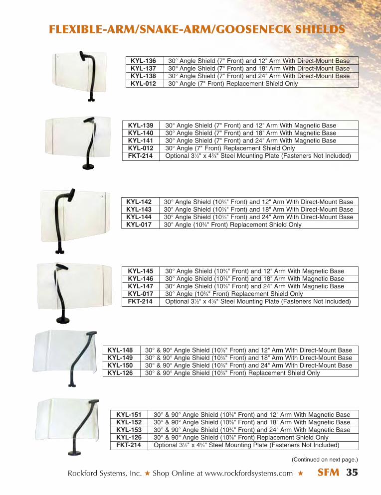
KYL-136 30° Angle Shield (7" Front) and 12" Arm With Direct-Mount BaseKYL-137 30° Angle Shield (7" Front) and 18" Arm With Direct-Mount BaseKYL-138 30° Angle Shield (7" Front) and 24" Arm With Direct-Mount BaseKYL-012 30° Angle (7" Front) Replacement Shield Only
KYL-139 30° Angle Shield (7" Front) and 12" Arm With Magnetic BaseKYL-140 30° Angle Shield (7" Front) and 18" Arm With Magnetic BaseKYL-141 30° Angle Shield (7" Front) and 24" Arm With Magnetic BaseKYL-012 30° Angle (7" Front) Replacement Shield OnlyFKT-214 Optional 31⁄2" x 45⁄8" Steel Mounting Plate (Fasteners Not Included)
KYL-142 30° Angle Shield (103⁄8" Front) and 12" Arm With Direct-Mount BaseKYL-143 30° Angle Shield (103⁄8" Front) and 18" Arm With Direct-Mount BaseKYL-144 30° Angle Shield (103⁄8" Front) and 24" Arm With Direct-Mount BaseKYL-017 30° Angle (103⁄8" Front) Replacement Shield Only
KYL-148 30° & 90° Angle Shield (103⁄8" Front) and 12" Arm With Direct-Mount BaseKYL-149 30° & 90° Angle Shield (103⁄8" Front) and 18" Arm With Direct-Mount BaseKYL-150 30° & 90° Angle Shield (103⁄8" Front) and 24" Arm With Direct-Mount BaseKYL-126 30° & 90° Angle Shield (103⁄8" Front) Replacement Shield Only
KYL-151 30° & 90° Angle Shield (103⁄8" Front) and 12" Arm With Magnetic BaseKYL-152 30° & 90° Angle Shield (103⁄8" Front) and 18" Arm With Magnetic BaseKYL-153 30° & 90° Angle Shield (103⁄8" Front) and 24" Arm With Magnetic BaseKYL-126 30° & 90° Angle Shield (103⁄8" Front) Replacement Shield OnlyFKT-214 Optional 31⁄2" x 45⁄8" Steel Mounting Plate (Fasteners Not Included)
(Continued on next page.)
KYL-145 30° Angle Shield (103⁄8" Front) and 12" Arm With Magnetic BaseKYL-146 30° Angle Shield (103⁄8" Front) and 18" Arm With Magnetic BaseKYL-147 30° Angle Shield (103⁄8" Front) and 24" Arm With Magnetic BaseKYL-017 30° Angle (103⁄8" Front) Replacement Shield OnlyFKT-214 Optional 31⁄2" x 45⁄8" Steel Mounting Plate (Fasteners Not Included)
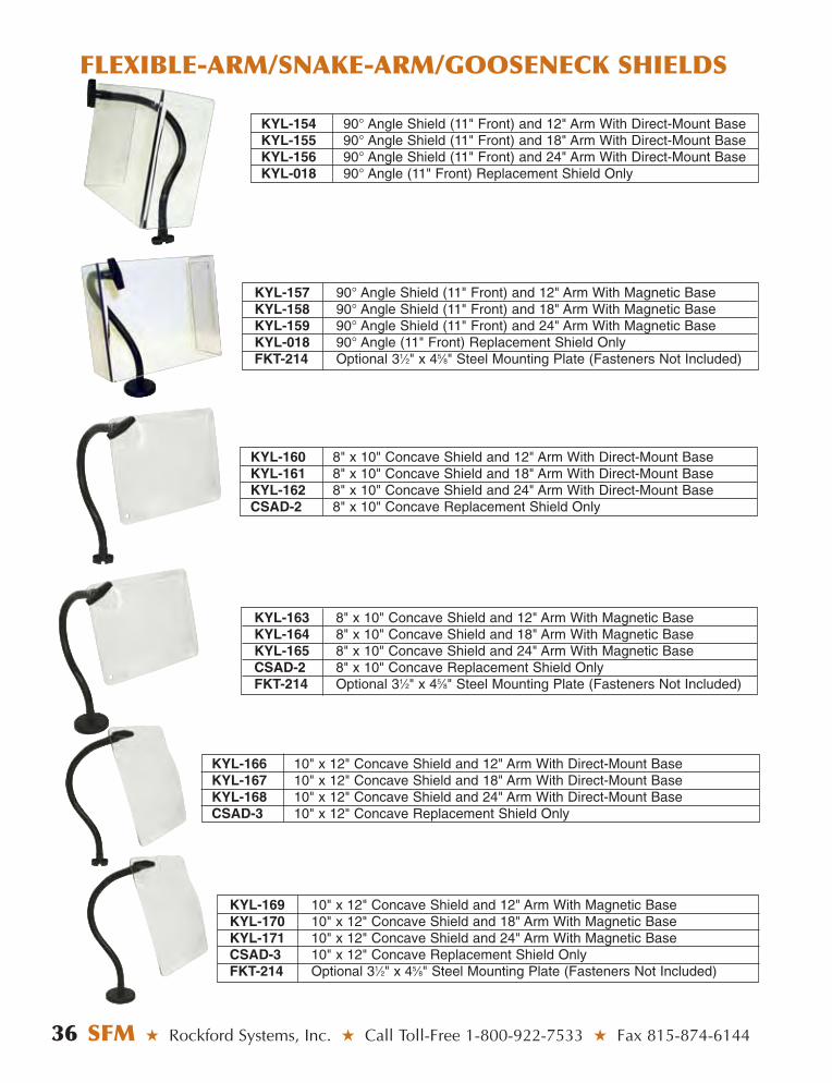
36 SFM ★ Rockford Systems, Inc. ★ Call Toll-Free 1-800-922-7533 ★ Fax 815-874-6144
FLEXIBLE-ARM/SNAKE-ARM/GOOSENECK SHIELDS
KYL-154 90° Angle Shield (11" Front) and 12" Arm With Direct-Mount BaseKYL-155 90° Angle Shield (11" Front) and 18" Arm With Direct-Mount BaseKYL-156 90° Angle Shield (11" Front) and 24" Arm With Direct-Mount BaseKYL-018 90° Angle (11" Front) Replacement Shield Only
KYL-157 90° Angle Shield (11" Front) and 12" Arm With Magnetic BaseKYL-158 90° Angle Shield (11" Front) and 18" Arm With Magnetic BaseKYL-159 90° Angle Shield (11" Front) and 24" Arm With Magnetic BaseKYL-018 90° Angle (11" Front) Replacement Shield OnlyFKT-214 Optional 31⁄2" x 45⁄8" Steel Mounting Plate (Fasteners Not Included)
KYL-160 8" x 10" Concave Shield and 12" Arm With Direct-Mount BaseKYL-161 8" x 10" Concave Shield and 18" Arm With Direct-Mount BaseKYL-162 8" x 10" Concave Shield and 24" Arm With Direct-Mount BaseCSAD-2 8" x 10" Concave Replacement Shield Only
KYL-163 8" x 10" Concave Shield and 12" Arm With Magnetic BaseKYL-164 8" x 10" Concave Shield and 18" Arm With Magnetic BaseKYL-165 8" x 10" Concave Shield and 24" Arm With Magnetic BaseCSAD-2 8" x 10" Concave Replacement Shield OnlyFKT-214 Optional 31⁄2" x 45⁄8" Steel Mounting Plate (Fasteners Not Included)
KYL-166 10" x 12" Concave Shield and 12" Arm With Direct-Mount BaseKYL-167 10" x 12" Concave Shield and 18" Arm With Direct-Mount BaseKYL-168 10" x 12" Concave Shield and 24" Arm With Direct-Mount BaseCSAD-3 10" x 12" Concave Replacement Shield Only
KYL-169 10" x 12" Concave Shield and 12" Arm With Magnetic BaseKYL-170 10" x 12" Concave Shield and 18" Arm With Magnetic BaseKYL-171 10" x 12" Concave Shield and 24" Arm With Magnetic BaseCSAD-3 10" x 12" Concave Replacement Shield OnlyFKT-214 Optional 31⁄2" x 45⁄8" Steel Mounting Plate (Fasteners Not Included)
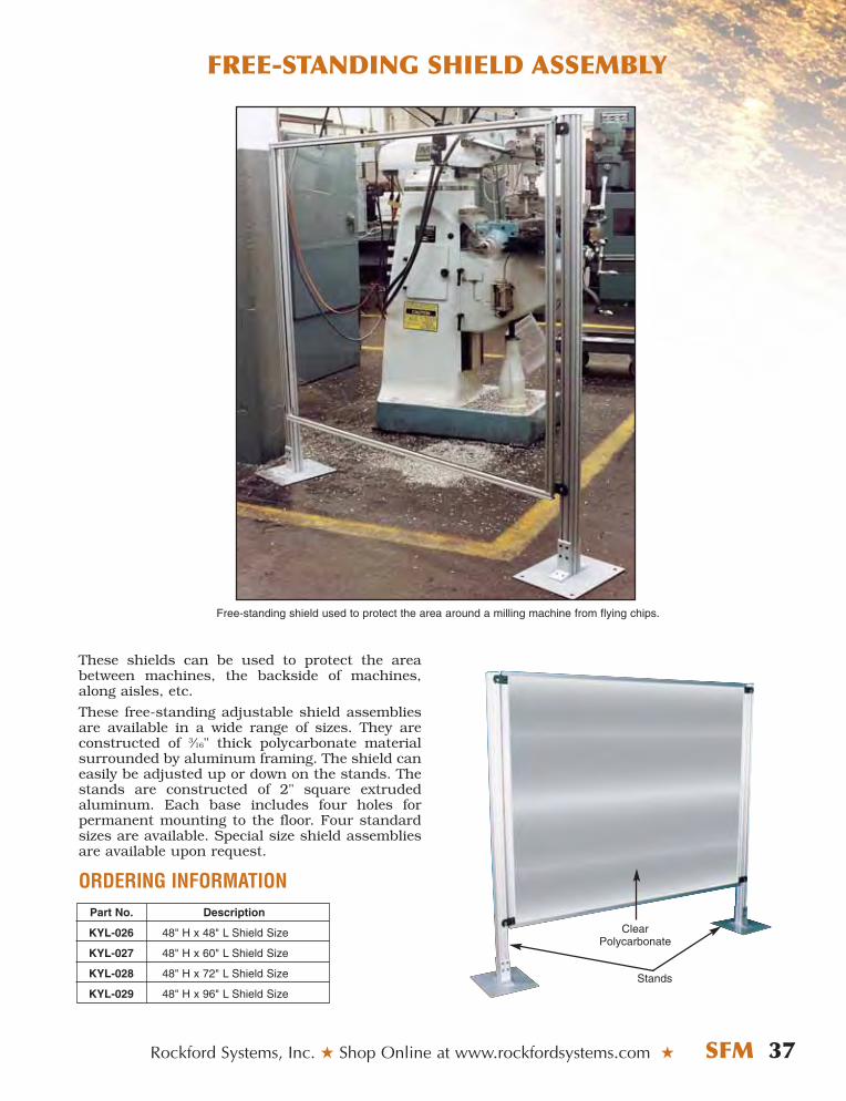
FREE-STANDING SHIELD ASSEMBLY
Rockford Systems, Inc. ★ Shop Online at www.rockfordsystems.com ★ SFM 37
Part No. Description
KYL-026 48" H x 48" L Shield Size
KYL-027 48" H x 60" L Shield Size
KYL-028 48" H x 72" L Shield Size
KYL-029 48" H x 96" L Shield Size
These shields can be used to protect the areabetween machines, the backside of machines,along aisles, etc.
These free-standing adjustable shield assembliesare available in a wide range of sizes. They areconstructed of 3⁄16" thick polycarbonate materialsurrounded by aluminum framing. The shield caneasily be adjusted up or down on the stands. Thestands are constructed of 2" square extruded aluminum. Each base includes four holes for permanent mounting to the floor. Four standardsizes are available. Special size shield assembliesare available upon request.
ORDERING INFORMATION
ClearPolycarbonate
Stands
Free-standing shield used to protect the area around a milling machine from flying chips.
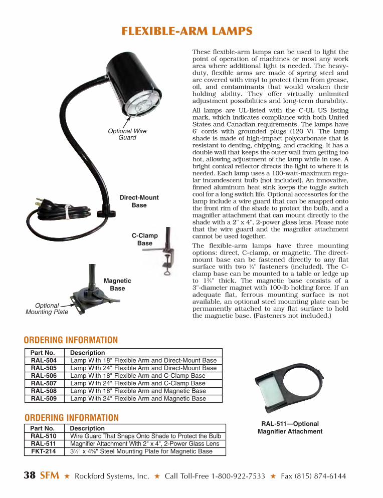
38 SFM ★ Rockford Systems, Inc. ★ Call Toll-Free 1-800-922-7533 ★ Fax (815) 874-6144
FLEXIBLE-ARM LAMPS
Part No. DescriptionRAL-504 Lamp With 18" Flexible Arm and Direct-Mount BaseRAL-505 Lamp With 24" Flexible Arm and Direct-Mount BaseRAL-506 Lamp With 18" Flexible Arm and C-Clamp BaseRAL-507 Lamp With 24" Flexible Arm and C-Clamp BaseRAL-508 Lamp With 18" Flexible Arm and Magnetic BaseRAL-509 Lamp With 24" Flexible Arm and Magnetic Base
ORDERING INFORMATION
Part No. DescriptionRAL-510 Wire Guard That Snaps Onto Shade to Protect the BulbRAL-511 Magnifier Attachment With 2" x 4", 2-Power Glass LensFKT-214 31⁄2" x 45⁄8" Steel Mounting Plate for Magnetic Base
ORDERING INFORMATION
These flexible-arm lamps can be used to light thepoint of operation of machines or most any workarea where additional light is needed. The heavy-duty, flexible arms are made of spring steel andare covered with vinyl to protect them from grease,oil, and contaminants that would weaken theirholding ability. They offer virtually unlimitedadjustment possibilities and long-term durability.
All lamps are UL-listed with the C-UL US listingmark, which indicates compliance with both UnitedStates and Canadian requirements. The lamps have6' cords with grounded plugs (120 V). The lampshade is made of high-impact polycarbonate that isresistant to denting, chipping, and cracking. It has adouble wall that keeps the outer wall from getting toohot, allowing adjustment of the lamp while in use. Abright conical reflector directs the light to where it isneeded. Each lamp uses a 100-watt-maximum regu-lar incandescent bulb (not included). An innovative,finned aluminum heat sink keeps the toggle switchcool for a long switch life. Optional accessories for thelamp include a wire guard that can be snapped ontothe front rim of the shade to protect the bulb, and amagnifier attachment that can mount directly to theshade with a 2" x 4", 2-power glass lens. Please notethat the wire guard and the magnifier attachmentcannot be used together.
The flexible-arm lamps have three mountingoptions: direct, C-clamp, or magnetic. The direct-mount base can be fastened directly to any flatsurface with two 1⁄4" fasteners (included). The C-clamp base can be mounted to a table or ledge upto 13⁄4" thick. The magnetic base consists of a 3"-diameter magnet with 100-lb holding force. If anadequate flat, ferrous mounting surface is notavailable, an optional steel mounting plate can bepermanently attached to any flat surface to holdthe magnetic base. (Fasteners not included.)
Direct-MountBase
Optional WireGuard
C-ClampBase
MagneticBase
RAL-511—OptionalMagnifier Attachment
OptionalMounting Plate
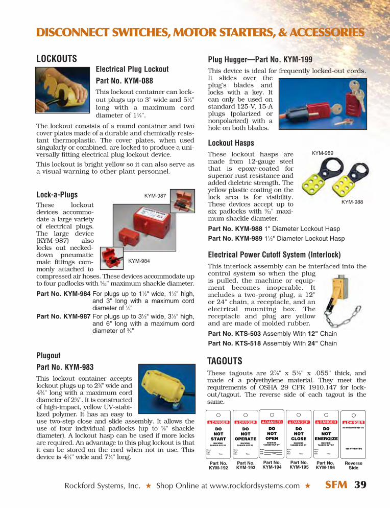
Rockford Systems, Inc. ★ Shop Online at www.rockfordsystems.com ★ SFM 39
DISCONNECT SWITCHES, MOTOR STARTERS, & ACCESSORIES
Part No.KYM-192
Part No.KYM-193
Part No.KYM-196
Part No.KYM-194
Part No.KYM-195
ReverseSide
TAGOUTSThese tagouts are 27⁄8" x 51⁄2" x .055" thick, andmade of a polyethylene material. They meet therequirements of OSHA 29 CFR 1910.147 for lock-out/tagout. The reverse side of each tagout is thesame.
LOCKOUTSElectrical Plug LockoutPart No. KYM-088This lockout container can lock-out plugs up to 3" wide and 51⁄2"long with a maximum corddiameter of 11⁄4".
The lockout consists of a round container and twocover plates made of a durable and chemically resis-tant thermoplastic. The cover plates, when usedsingularly or combined, are locked to produce a uni-versally fitting electrical plug lockout device.
This lockout is bright yellow so it can also serve asa visual warning to other plant personnel.
Lock-a-PlugsThese lockoutdevices accommo-date a large varietyof electrical plugs.The large device(KYM-987) alsolocks out necked-down pneumaticmale fittings com-monly attached tocompressed air hoses. These devices accommodate upto four padlocks with 9⁄32" maximum shackle diameter.
Part No. KYM-984 For plugs up to 11⁄2" wide, 11⁄2" high,and 3" long with a maximum corddiameter of 1⁄2"
Part No. KYM-987 For plugs up to 31⁄2" wide, 31⁄2" high,and 6" long with a maximum corddiameter of 3⁄4"
PlugoutPart No. KYM-983This lockout container acceptslockout plugs up to 23⁄4" wide and43⁄4" long with a maximum corddiameter of 23⁄4". It is constructedof high-impact, yellow UV-stabi-lized polymer. It has an easy touse two-step close and slide assembly. It allows theuse of four individual padlocks (up to 3⁄8" shacklediameter). A lockout hasp can be used if more locksare required. An advantage to this plug lockout is thatit can be stored on the cord when not in use. Thisdevice is 41⁄4" wide and 71⁄4" long.
Plug Hugger—Part No. KYM-199 This device is ideal for frequently locked-out cords.It slides over theplug’s blades andlocks with a key. Itcan only be used onstandard 125-V, 15-Aplugs (polarized ornonpolarized) with ahole on both blades.
Lockout HaspsThese lockout hasps aremade from 12-gauge steelthat is epoxy-coated forsuperior rust resistance andadded dieletric strength. Theyellow plastic coating on thelock area is for visibility.These devices accept up tosix padlocks with 9⁄32" maxi-mum shackle diameter.
Part No. KYM-988 1" Diameter Lockout Hasp
Part No. KYM-989 11⁄2" Diameter Lockout Hasp
Electrical Power Cutoff System (Interlock)This interlock assembly can be interfaced into thecontrol system so when the plugis pulled, the machine or equip-ment becomes inoperable. Itincludes a two-prong plug, a 12"or 24" chain, a receptacle, and anelectrical mounting box. Thereceptacle and plug are yellowand are made of molded rubber.
Part No. KTS-503 Assembly With 12" Chain
Part No. KTS-518 Assembly With 24" Chain
KYM-988
KYM-989
KYM-984
KYM-987

LOCKOUT VALVES SLIDE-OPERATED VALVEThis three-way valve is operated with the manual movement of a slidethat opens and closes the valve. This valve shuts off air at the press andthen bleeds off downstream air. It can be locked only in the off position.
EEZ-ON VALVEThis valve shuts off air supply to the machine and bleedsdownstream air when the valve is closed. When the valveis open, it gradually allows air into the air system to pre-vent damage to air components. It can be locked only inthe off position. This valve is furnished with a muffler.
40 SFM ★ Rockford Systems, Inc. ★ Call Toll-Free 1-800-922-7533 ★ Fax 815-874-6144
SSIINNGGLLEE--PPHHAASSEE DISCONNECT SWITCH WITH MAGNETIC MOTOR STARTER AND SELF-LATCHING EMERGENCY-STOP BUTTONThis single-phase unit is designed for motors that have built-in overloads. Typical applications for thesecombinations include smaller crimping machines, grinders, drill presses, and all types of saws.
Part No. CSS-055 (115 V, 1⁄2 HP max.)The 115-V, 15-A disconnect switch and nonreversing magnetic motor starter arehoused in a NEMA 12 enclosure. Enclosure size is 8" x 6" x 31⁄2". It includes a self-latching red emergency-stop palm button and a green motor control start pushbutton. It can be used on machines with 115-V power and is rated up to 1⁄2 HPmaximum.
The disconnect switch has a rotary operating handle which is lockable in the offposition only. This meets OSHA regulations and ANSI standards.
For machines with 230-V AC single-phase motors, a transformer is required to reducethe control circuit voltage to 115-V AC in order to comply with NFPA 79. See the RSDseries disconnect switches, motor starters, and combinations on pages 41-42.
SSIINNGGLLEE--PPHHAASSEE STARTER WITH SELF-LATCHING EMERGENCY-STOP BUTTONPart No. CSF-082 (115 V, 1⁄2 HP max.)The 115-V, 15-A nonreversing magnetic motor starter, self-latching red emergency-stop palm button, and green motor control start push button are housed in a NEMA4 polycarbonate enclosure. Enclosure size is 41⁄4" x 41⁄4" x 31⁄2". It can be used formachines with 115-V power and is rated up to 1⁄2 HP maximum.
For machines with 230-V AC single-phase motors, a transformer is required toreduce the control circuit voltage to 115-V AC in order to comply with NFPA 79. Seethe RSD series disconnect switches, motor starters, and combinations on pages 41-42.
Part No. CSF-301 (115 V, 2 HP max.)The 115-V, 30-A nonreversing magnetic motor starter, self-latching red emer-gency-stop palm button, and green motor control start push button are housedin a NEMA 12 enclosure. Enclosure size is 8" x 6" x 6". It can be used formachines with 115-V power and is rated up to 2 HP maximum.
For machines with 230-V AC single-phase motors, a transformer is required toreduce the control circuit voltage to 115-V AC in order to comply with NFPA79. See the RSD series disconnect switches, motor starters, and combinationson pages 41-42.
DISCONNECT SWITCHES, MOTOR STARTERS, & ACCESSORIES
Port SizePart No. In-Out Exh.RCD-121 1⁄2" 3⁄4"RCD-122 3⁄4" 3⁄4"
Port SizePart No. In-OutRCD-113 1⁄2"RCD-114 3⁄4"

Rockford Systems, Inc. ★ Shop Online at www.rockfordsystems.com ★ SFM 41
DISCONNECT SWITCHES, MOTOR STARTERS, & ACCESSORIES
ENCLOSED TRANSFORMERS
These transformers comply with OSHA regulations and ANSI standardsand are available for use when the motor start/stop station is remotelylocated from the starter enclosure, and voltage to these buttons must be115 V or less. These transformers mount directly to the frame of themachine. If the existing motor starter operating coils are a higher voltage(208, 230, 460, 575 V), they must be replaced with a 115-V coil whenfurnishing these transformers. A replaceable fuse is accessible from theoutside of the transformer housing.
Externally MountedTransformer
IEC FUSED DISCONNECT SWITCHES, MAGNETIC MOTOR STARTERS, AND COMBINATIONS
Part No. RSD-1230-F
These three-phase disconnect/starters are housed in a NEMA 12metal enclosure. The enclosure size will vary depending on the motorstarter required. These units can be used on machines with 208, 230,460, or 575 V. They are furnished with an overload relay and haveoperating coils of 115 V, 60 Hz. The disconnect operating handle islockable in the off position only. These combination units meet OSHAregulations, ANSI standards, and NFPA 79.
To obtain the part number ofthe motor starter required,please refer to the part num-bering chart on the nextpage.
A remote station is requiredwhen using any plain-doorstarter. To obtain the partnumber of the remote opera-tor station required, pleaserefer to the part numberingchart on the page 43.
Please furnish the exact motor horsepower, voltage, and full-load amps when ordering any of the disconnects or starters on page 42. This information is usually on the motor nameplate. Voltage can be 208, 230, 460, or 575 V. If other sizes are required, please consult the factory.
Part No. RSD-2210-P-1
Part No.VOS-2100
Part No. Description
RSF-021 100-VA, 230/460-V primary and 115-V fused secondary with a 1 A, 230-V fuse
RSF-030 150-VA, 230/460-V primary and 115-V fused secondary with a 1.5 A, 230-V fuse
ORDERING INFORMATION
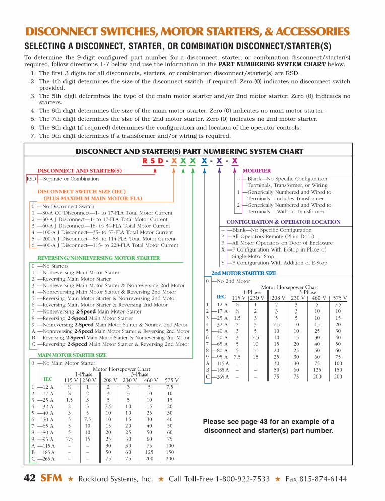
DISCONNECT SWITCHES, MOTOR STARTERS, & ACCESSORIES
42 SFM ★ Rockford Systems, Inc. ★ Call Toll-Free 1-800-922-7533 ★ Fax 815-874-6144
SELECTING A DISCONNECT, STARTER, OR COMBINATION DISCONNECT/STARTER(S)To determine the 9-digit configured part number for a disconnect, starter, or combination disconnect/starter(s)required, follow directions 1-7 below and use the information in the PART NUMBERING SYSTEM CHART below.
1. The first 3 digits for all disconnects, starters, or combination disconnect/starter(s) are RSD.2. The 4th digit determines the size of the disconnect switch, if required. Zero (0) indicates no disconnect switch
provided.3. The 5th digit determines the type of the main motor starter and/or 2nd motor starter. Zero (0) indicates no
starters.4. The 6th digit determines the size of the main motor starter. Zero (0) indicates no main motor starter.5. The 7th digit determines the size of the 2nd motor starter. Zero (0) indicates no 2nd motor starter.6. The 8th digit (if required) determines the configuration and location of the operator controls.7. The 9th digit determines if a transformer and/or wiring is required.
DISCONNECT AND STARTER(S)
RSD —Separate or Combination
DISCONNECT SWITCH SIZE (IEC) (PLUS MAXIMUM MAIN MOTOR FLA)
0 —No Disconnect Switch1 —30-A CC Disconnect—1- to 17-FLA Total Motor Current2 —30-A J Disconnect—1- to 17-FLA Total Motor Current 3 —60-A J Disconnect—18- to 34-FLA Total Motor Current4 —100-A J Disconnect—35- to 57-FLA Total Motor Current5 —200-A J Disconnect—58- to 114-FLA Total Motor Current6 —400-A J Disconnect—115- to 228-FLA Total Motor Current
REVERSING/NONREVERSING MOTOR STARTER
0 —No Starters1 —Nonreversing Main Motor Starter2 —Reversing Main Motor Starter3 —Nonreversing Main Motor Starter & Nonreversing 2nd Motor4 —Nonreversing Main Motor Starter & Reversing 2nd Motor5 —Reversing Main Motor Starter & Nonreversing 2nd Motor6 —Reversing Main Motor Starter & Reversing 2nd Motor7 —Nonreversing 2-Speed Main Motor Starter8 —Reversing 2-Speed Main Motor Starter9 —Nonreversing 2-Speed Main Motor Starter & Nonrev. 2nd MotorA —Nonreversing 2-Speed Main Motor Starter & Reversing 2nd MotorB —Reversing 2-Speed Main Motor Starter & Nonreversing 2nd MotorC —Reversing 2-Speed Main Motor Starter & Reversing 2nd Motor
MAIN MOTOR STARTER SIZE
0 —No Main Motor Starter
IEC
1 —12 A 2 —17 A 3 —25 A 4 —32 A 5 —40 A 6 —50 A 7 —65 A8 —80 A 9 —95 A A —115 AB —185 A C —265 A
MODIFIER
-- —Blank—No Specific Configuration,Terminals, Transformer, or Wiring
1 —Generically Numbered and Wired to Terminals—Includes Transformer
2 —Generically Numbered and Wired toTerminals —Without Transformer
CONFIGURATION & OPERATOR LOCATION
-- —Blank—No Specific ConfigurationP —All Operators Remote (Plain Door)F —All Motor Operators on Door of EnclosureX —F Configuration With E-Stop in Place of
Single-Motor StopY —F Configuration With Addition of E-Stop
2nd MOTOR STARTER SIZE
0 —No 2nd Motor
IEC
1 —12 A 2 —17 A 3 —25 A 4 —32 A 5 —40 A 6 —50 A 7 —65 A8 —80 A 9 —95 A A —115 AB —185 A C —265 A
DISCONNECT AND STARTER(S) PART NUMBERING SYSTEM CHARTR S D - X X X X - X - X
Motor Horsepower Chart1-Phase 3-Phase
115 V 230 V 208 V 230 V 460 V 575 V1⁄2 1 2 3 5 7.53⁄4 2 3 3 10 10
1.5 3 5 5 10 152 3 7.5 10 15 203 5 10 10 25 303 7.5 10 15 30 405 10 15 20 40 505 10 20 25 50 60
7.5 15 25 30 60 75– – 30 30 75 100– – 50 60 125 150– – 75 75 200 200
Motor Horsepower Chart1-Phase 3-Phase
115 V 230 V 208 V 230 V 460 V 575 V1⁄2 1 2 3 5 7.53⁄4 2 3 3 10 10
1.5 3 5 5 10 152 3 7.5 10 15 203 5 10 10 25 303 7.5 10 15 30 405 10 15 20 40 505 10 20 25 50 60
7.5 15 25 30 60 75– – 30 30 75 100– – 50 60 125 150– – 75 75 200 200
Please see page 43 for an example of adisconnect and starter(s) part number.
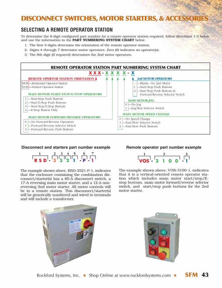
DISCONNECT SWITCHES, MOTOR STARTERS, & ACCESSORIES
Rockford Systems, Inc. ★ Shop Online at www.rockfordsystems.com ★ SFM 43
R S D - 3 5 2 1 - P - 1
1 2
The example shown above, RSD-3521-P-1, indicatesthat the enclosure containing the combination dis-connect/starter(s) has a 60-A disconnect switch, a17-A reversing main motor starter, and a 12-A non-reversing 2nd motor starter. All motor controls willbe in a remote station. This disconnect/starter(s)will be generically numbered and wired to terminalsand will include a transformer.
SELECTING A REMOTE OPERATOR STATIONTo determine the 8-digit configured part number for a remote operator station required, follow directions 1-3 belowand use the information in the PART NUMBERING SYSTEM CHART below.
1. The first 3 digits determine the orientation of the remote operator station.2. Digits 4 through 7 determine motor operators. Zero (0) indicates no operator(s).3. The 8th digit (if required) determines the 2nd motor operators.
REMOTE OPERTOR STATION ORIENATION
HOS—Horizontal Operator StationVOS —Vertical Operator Station
MAIN MOTOR START/STOP/E-STOP OPERATORS
1 —Start/Stop Push Buttons2 —Start/E-Stop Push Buttons3 —Start/Stop/E-Stop Buttons4 —E-Stop Button Only
MAIN MOTOR FORWARD/REVERSE OPERATORS
0 —No Forward/Reverse Operators1 —Forward/Reverse Selector Switch2 —Forward/Reverse Push Buttons
2nd MOTOR OPERATORS
-- —Blank—No 2nd Motor1 —Start/Stop Push Buttons2 —Start/Stop Push Buttons &
Forward/Reverse Selector Switch
MAIN MOTOR JOG0 —No Jog1 —Jog/Run Selector Switch
MAIN MOTOR SPEED CHANGE
0 —No Speed Change1 —Fast/Slow Selector Switch2 —Fast/Slow Push Buttons
REMOTE OPERATOR STATION PART NUMBERING SYSTEM CHARTX X X - X X X X - X
3 4 5 6 7
VOS - 3 1 0 0 - 1
1
The example shown above, VOS-3100-1, indicatesthat it is a vertical-oriented remote operator sta-tion which includes main motor start/stop/E-stop buttons, main motor forward/reverse selectorswitch, and start/stop push buttons for the 2ndmotor starter.
2
Disconnect and starters part number example Remote operator part number example
3
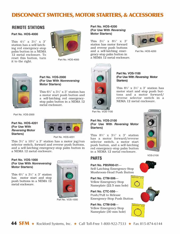
44 SFM ★ Rockford Systems, Inc. ★ Call Toll-Free 1-800-922-7533 ★ Fax 815-874-6144
DISCONNECT SWITCHES, MOTOR STARTERS, & ACCESSORIES
Part No. HOS-4000
This 41⁄2" x 31⁄2" x 3" station has a self-latch-ing red emergency-stoppalm button in a NEMA12 metal enclosure. Toreset this button, turnit to the right.
Part No. VOS-2000 (For Use With NonreversingMotor Starters)
This 63⁄4" x 31⁄2" x 3" station hasa motor start push button and a self-latching red emergency-stop palm button in a NEMA 12metal enclosure.
Part No. HOS-4201 (For Use WithReversing MotorStarters)
This 31⁄2" x 101⁄2" x 3" station has a motor jog/runselector switch, forward and reverse push buttons,and a self-latching emergency-stop palm button ina NEMA 12 metal enclosure.
Part No. VOS-1000 (For Use With NonreversingMotor Starters)
This 63⁄4" x 31⁄2" x 3" stationhas motor start and stoppush buttons in a NEMA 12metal enclosure.
REMOTE STATIONS
Part No. VOS-2000
Part No. HOS-4000
Part No. HOS-4200 (For Use With ReversingMotor Starters)
This 31⁄2" x 83⁄4" x 3" station has motor forwardand reverse push buttonsand a self-latching emer-gency-stop palm button ina NEMA 12 metal enclosure.
Part No. VOS-1100(For Use With Reversing MotorStarters)
This 83⁄4" x 31⁄2" x 3" station hasmotor start and stop push but-tons and a motor forward/reverse selector switch in aNEMA 12 metal enclosure.
Part No. VOS-2100 (For Use With Reversing MotorStarters)
This 83⁄4" x 31⁄2" x 3" station has a motor forward/reverseselector switch, a motor startpush button, and a self-latchingred emergency-stop palm buttonin a NEMA 12 metal enclosure.
Part No. VOS-1000
Part No. HOS-4200
Part No. VOS-1100
VOS-2100
Part No. HOS-4201
PARTSPart No. PB5R00-01—Self-Latching Emergency-Stop Mushroom-Head Push Button
Part No. CTM-506—Yellow Emergency-StopNameplate (22.5 mm hole)
Part No. CTC-550—Push/Pull to ReleaseEmergency-Stop Push Button
Part No. CTM-548—Yellow Emergency-Stop Nameplate (30 mm hole)
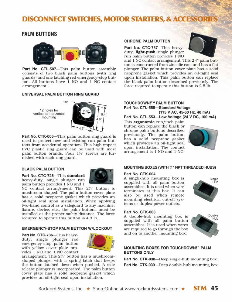
Rockford Systems, Inc. ★ Shop Online at www.rockfordsystems.com ★ SFM 45
DISCONNECT SWITCHES, MOTOR STARTERS, & ACCESSORIES
CHROME PALM BUTTON
Part No. CTC-737—This heavy-duty, light-push single plungerrun palm button provides 1 NOand 1 NC contact arrangement. This 21⁄4" palm but-ton is constructed from zinc die cast and has a flatplunger. The palm button cover plate has a solidneoprene gasket which provides an oil-tight sealupon installation. This palm button can replacethe black palm button described previously. Theforce required to operate this button is 2.5 lb.
TOUCHDOWN!™ PALM BUTTONPart No. CTL-555—Standard Voltage
(115 V AC, 45-60 Hz, 40 mA)Part No. CTL-553—Low Voltage (24 V DC, 100 mA) This ergonomic run/inch palmbutton can replace the black orchrome palm buttons describedpreviously. The palm buttonhas a solid neoprene gasketwhich provides an oil-tight sealupon installation. The contactarrangement is 1 NO and 1 NC.
MOUNTING BOXES (WITH 3⁄4" NPT THREADED HUBS)
Part No. CTK-004A single-hub mounting box issupplied with all palm buttonassemblies. It is used when wireterminates at this box. It canalso be used when remotemounting electrical cut-off sys-tems or duplex power outlets.
Part No. CTK-003A double-hub mounting box issupplied with all palm buttonassemblies. It is used when wiresare required to go through the boxand on to another mounting box.
MOUNTING BOXES FOR TOUCHDOWN! ™ PALMBUTTONS ONLY
Part No. CTK-038—Deep single-hub mounting box
Part No. CTK-039—Deep double-hub mounting box
Part No. CTK-006—This palm button ring guard isused to protect new and existing run palm but-tons from accidental operation. This high-impactPVC plastic ring guard can be used with mostpalm button brands. Four 11⁄4" screws are fur-nished with each ring guard.
Part No. CTL-507—This palm button assemblyconsists of two black palm buttons (with ringguards) and one latching red emergency-stop but-ton. All buttons have 1 NO and 1 NC contactarrangement.
DoubleHub
BLACK PALM BUTTON
Part No. CTC-726—This standardheavy-duty, single plunger runpalm button provides 1 NO and 1NC contact arrangement. This 21⁄4" button ismushroom-shaped. The palm button cover platehas a solid neoprene gasket which provides anoil-tight seal upon installation. When applyingtwo-hand control as a safeguard to any machine,fixture, device, etc., the palm buttons must beinstalled at the proper safety distance. The forcerequired to operate this button is 4.3 lb.
EMERGENCY-STOP PALM BUTTON W/LOCKOUT
Part No. CTC-736—This heavy-duty, single plunger redemergency-stop palm buttonwith yellow cover plate pro-vides 1 NO and 1 NC contactarrangement. This 21⁄4" button has a mushroom-shaped plunger with a spring latch that keepsthe button latched down when pushed. A siderelease plunger is incorporated. The palm buttoncover plate has a solid neoprene gasket whichprovides an oil-tight seal upon installation.
SingleHub
12 holes for vertical or horizontal
mounting5.4"
4.9"
2.8"
.18"
4.9"
UNIVERSAL PALM BUTTON RING GUARD
PALM BUTTONS
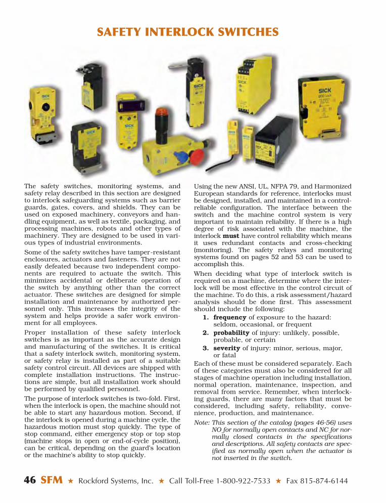
46 SFM ★ Rockford Systems, Inc. ★ Call Toll-Free 1-800-922-7533 ★ Fax 815-874-6144
SAFETY INTERLOCK SWITCHES
Using the new ANSI, UL, NFPA 79, and HarmonizedEuropean standards for reference, interlocks mustbe designed, installed, and maintained in a control-reliable configuration. The interface between theswitch and the machine control system is veryimportant to maintain reliability. If there is a highdegree of risk associated with the machine, theinterlock must have control reliability which meansit uses redundant contacts and cross-checking(monitoring). The safety relays and monitoring systems found on pages 52 and 53 can be used toaccomplish this.
When deciding what type of interlock switch isrequired on a machine, determine where the inter-lock will be most effective in the control circuit ofthe machine. To do this, a risk assessment/hazardanalysis should be done first. This assessmentshould include the following:
1. frequency of exposure to the hazard:seldom, occasional, or frequent
2. probability of injury: unlikely, possible,probable, or certain
3. severity of injury: minor, serious, major,or fatal
Each of these must be considered separately. Eachof these categories must also be considered for allstages of machine operation including installation,normal operation, maintenance, inspection, andremoval from service. Remember, when interlock-ing guards, there are many factors that must beconsidered, including safety, reliability, conve-nience, production, and maintenance.
Note: This section of the catalog (pages 46-56) usesNO for normally open contacts and NC for nor-mally closed contacts in the specificationsand descriptions. All safety contacts are spec-ified as normally open when the actuator isnot inserted in the switch.
The safety switches, monitoring systems, andsafety relay described in this section are designedto interlock safeguarding systems such as barrierguards, gates, covers, and shields. They can beused on exposed machinery, conveyors and han-dling equipment, as well as textile, packaging, andprocessing machines, robots and other types ofmachinery. They are designed to be used in vari-ous types of industrial environments.
Some of the safety switches have tamper-resistantenclosures, actuators and fasteners. They are noteasily defeated because two independent compo-nents are required to actuate the switch. Thisminimizes accidental or deliberate operation ofthe switch by anything other than the correctactuator. These switches are designed for simpleinstallation and maintenance by authorized per-sonnel only. This increases the integrity of thesystem and helps provide a safer work environ-ment for all employees.
Proper installation of these safety interlockswitches is as important as the accurate designand manufacturing of the switches. It is criticalthat a safety interlock switch, monitoring system,or safety relay is installed as part of a suitablesafety control circuit. All devices are shipped withcomplete installation instructions. The instruc-tions are simple, but all installation work shouldbe performed by qualified personnel.
The purpose of interlock switches is two-fold. First,when the interlock is open, the machine should notbe able to start any hazardous motion. Second, ifthe interlock is opened during a machine cycle, thehazardous motion must stop quickly. The type ofstop command, either emergency stop or top stop(machine stops in open or end-of-cycle position),can be critical, depending on the guard’s locationor the machine’s ability to stop quickly.

Rockford Systems, Inc. ★ Shop Online at www.rockfordsystems.com ★ SFM 47
SAFETY INTERLOCK SWITCHES
STANDARD SAFETY SWITCHESEither tamper-resistant safety switch can be used to interlock hinged, sliding, or lift-off guards. Closure ofthe guard or latch causes the actuator to enter the switch and release the dual antitamper locking cams. Theactuator allows the main center cam to rotate and make the switch contacts. When opening the guard orlatch, the actuator positively forces the contacts open due to the cam action built into the switch.
These versatile switches have multiple actuation entry positions. Actuators and conduit adapter aresold separately.
TECHNICAL SPECIFICATIONSSafety Contacts ....................................................2 NO Auxiliary Contact ....................................................1 NCActuator Entry Positions................................................3Switching Ability ........2 A @ 250 V AC, 2 A @ 24 V DCOperating Temperature................................-4° to 176°F
(-20° to 80°C)Switch Dimensions ......................3.7" H x 2" W x 1.2" D
(95 H x 52 W x 32 D mm)
Part No. 6025067 Standard Safety Switch (Actuator andConduit Adapter Sold Separately)
TECHNICAL SPECIFICATIONSSafety Contacts ....................................................3 NO Auxiliary Contact ....................................................1 NCActuator Entry Positions................................................5Switching Ability ........3 A @ 240 V AC, 3 A @ 24 V DCOperating Temperature................................-4° to 176°F
(-20° to 80°C)Switch Dimensions....................4.5" H x 1.5" W x 1.6" D
(116.5 H x 40 W x 43 D mm)
Part No. 6025073 Standard Safety Switch With DDiiee--CCaassttZZiinncc HHoouussiinngg (Actuator and ConduitAdapter Sold Separately)
Safety contacts are normally open (NO) when the switch is in the position shown, without the actuator inserted.
ACTUATORSPart No. 5311130 Straight Actuator
ACTUATORS
Part No. 5311134 Straight Actuator
Part No. 5311129 Fully Flexible Actuator15° Adjustability AllDirections
Part No. 5311278 Semi-Flexible Actuator15° Lateral Adjustability
Part No. 5311135 Fully Flexible Actuator15° Adjustability AllDirections
CONDUIT ADAPTER
Part No. 5312998M20 to 1⁄2" Conduit Adapter
CONDUIT ADAPTER
Part No. 5312998M20 to 1⁄2" Conduit Adapter

48 SFM ★ Rockford Systems, Inc. ★ Call Toll-Free 1-800-922-7533 ★ Fax 815-874-6144
SAFETY INTERLOCK SWITCHES
COMPACT SAFETY SWITCH
This compact switch is designed for tight spaces. The switch body is 1.2" (31 mm) wide. It works on the sameprinciples as the standard switches described on the previous page.
The head of this switch can rotate every 90° which allows the actuator to enter the switch from five (5)different positions. It provides both side and end actuator entry.
Actuators and conduit adapter are sold separately.
TECHNICAL SPECIFICATIONSSafety Contacts ....................................................2 NO Auxiliary Contact ....................................................1 NCActuator Entry Positions................................................5Switching Ability....................................3 A @ 240 V AC
3 A @ 24 V DCOperating Temperature ..............................-4° to 176°F
(-20° to 80°C)Case ..................Glass-Fiber Reinforced ThermoplasticOperating Head ..................................Rotates Every 90°
Switch Dimensions ..................3.5" H x 1.2" W x 1.1" D(90.5 H x 31 W x 30 D mm)
Part No. 6025059 Compact Safety Switch (Actuator andConduit Adapter Sold Separately)
Safety contacts are normally open (NO) when the switch is in the position shown, without the actuator inserted.
ACTUATORS
Part No. 5311131 Straight Actuator
Part No. 5311132 Angled Actuator
Part No. 5308842 Semi Flexible Actuator15° Lateral Adjustability
CONDUIT ADAPTER
Part No. 5311531M16 to 1⁄2" Conduit Adapter

Part No. 5306530 Rubber-Mounted Straight Actuator
ACTUATORSPart No. 5306527 Straight Actuator
Rockford Systems, Inc. ★ Shop Online at www.rockfordsystems.com ★ SFM 49
SAFETY INTERLOCK SWITCHES
These switches are designed to prevent accidentalor deliberate access while the machine is in motion.The mechanical locking feature is ideal formachines that have to finish a sequence, a program,or coast to a stop before the interlocked guard can beopened. The switches allow the guard to be mountedcloser to the hazard than nonlocking switches.
The operating principle of these switches is sim-ple. When the actuator enters the switch, itengages with and operates a tamper-resistantlocking mechanism, closing the contacts in a sim-ilar way to the standard switches on page 47. Thislocks the actuator in and holds the guard closed.When the contacts are closed and the mechanismis locked in, the machine is allowed to start.
TECHNICAL SPECIFICATIONSSafety Contacts ......................................................2 NO Auxiliary Contact ....................................................1 NCDoor Monitoring Contact ........................................1 NOActuator Entry Positions................................................5Locking Force......................................................1200 NSwitching Ability....................................4 A @ 230 V AC
4 A @ 24 V DCOperating Temperature ..............................-4° to 131°F
(-20° to 55°C)Case ..................Glass-Fiber Reinforced ThermoplasticOperating Head ..................................Rotates Every 90°
Switch Dimensions ..................7.5" H x 1.5" W x 1.6" D(192 H x 40 W x 42 D mm)
Part No. 6022580 Light Duty Safety Switch (Actuatorand Conduit Adapter Sold Separately)
To open the guard, a separate signal is required toenergize the solenoid which releases the lockingmechanism after the machine has stopped or thecycle has finished. A timer or stopped-motion detec-tor can be used for this signal (see pages 51-52). Thetimer can be used on machines with a consistentcoastdown time. The stopped-motion detector isavailable for machines that have a variable orinconsistent coastdown time. If power is lost, asupervised override mechanical release, built intothe switch, can be used.
Actuators and conduit adapter are sold separately.
LOCKING SAFETY SWITCHES
LIGHT-DUTY LOCKING SAFETY SWITCH
Safety contacts are normally open (NO) when theswitch is in the position shown, without the actuatorinserted.
CONDUIT ADAPTER
Part No. 5312998M20 to 1⁄2" Conduit Adapter Part No. 5306528 Semi-Flexible Actuator
15° Lateral Adjustability
Part No. 5306535 Angled Acuator

Part No. 5308759 Fully Flexible Actuator15° Adjustability all Directions
ACTUATORSPart No. 5308758 Straight Actuator
50 SFM ★ Rockford Systems, Inc. ★ Call Toll-Free 1-800-922-7533 ★ Fax 815-874-6144
SAFETY INTERLOCK SWITCHES
MEDIUM-DUTY LOCKING SAFETY SWITCH
TECHNICAL SPECIFICATIONSSafety Contacts ......................................................2 NO Auxiliary Contact ....................................................1 NCActuator Entry Positions................................................3Locking Force......................................................1200 NSwitching Ability....................................2 A @ 250 V AC
2 A @ 24 V DCOperating Temperature ..............................14° to 140°F
(-10° to 60°C)Case ..................Glass-Fiber Reinforced ThermoplasticSwitch Dimensions ..................4.7" H x 2.2" W x 1.4" D
(120 H x 58 W x 37 D mm)
Part No. 6025060 Medium-Duty Safety Switch (Actuatorand Conduit Adapter Sold Separately)
HEAVY-DUTY LOCKING SAFETY SWITCH
TECHNICAL SPECIFICATIONSSafety Contacts ......................................................2 NO Door Monitoring Safety Contacts ..........................2 NODoor Monitoring Auxiliary Contact ..........................1 NCActuator Entry Positions................................................3Locking Force......................................................2000 NSwitching Ability....................................2 A @ 250 V AC
2 A @ 24 V DCOperating Temperature ..............................-4° to 140°F
(-20° to 60°C)Case ..........................Glass-Fiber Reinforced PolyesterSwitch Dimensions ..................5.1" H x 3.6" W x 1.4" D
(130 H x 93 W x 37 D mm)
Part No. 6025115 Heavy-Duty Safety Switch (Actuatorand Conduit Adapter Sold Separately)
ACTUATORPart No. 5311133 Straight Actuator
Safety contacts are normally open (NO) when the switch is in the position shown, without the actuator inserted.
CONDUIT ADAPTER
Part No. 5312998M20 to 1⁄2" Conduit Adapter
CONDUIT ADAPTER
Part No. 5312998M20 to 1⁄2" Conduit Adapter

Rockford Systems, Inc. ★ Shop Online at www.rockfordsystems.com ★ SFM 51
SAFETY INTERLOCK SWITCHES
STOPPED-MOTION DETECTORThe stopped-motion detector is designed to beused with locking safety switches (see pages 49-50) that are applied to machines or robots with aninconsistent or variable coastdown time.
The stopped-motion detector has an on-delay thatcan be adjusted between 0.1 second and 40 minutesthrough a series of four time ranges. It also uses twoindependent proximity sensors and monitors twomoving metal parts of the machine or robot. Thismeans it can detect when hazardous motion hasstopped. Should either sensor detect motion, themachine guard will remain locked. This capability isessential on machines which do not have a consis-tent coastdown time.
SENSOR SPECIFICATIONSSensor Type ......................................................................Shielded, InductiveOperating Voltage ....................................................................10-30 V DCOutputs ....................................1 NO NPN Sensor and 1 NO PNP SensorOperating Temperature ....................................-13° to 158°F (-25° to 70°C)Cable ..........6.7' (2 m) of Prewired 3-Conductor Flexible Cable (14 AWG)Sensor Dimensions .......................0.71" Diameter (M18 x 1 Thread Size)
x 2" Long (50.8 mm)
TECHNICAL SPECIFICATIONSPower Supply ..............................................24 V AC/DC or 115/230 V ACRelay Outputs ....................................................................2 NO and 1 NCMaximum Switching Ability ..............................................4 A @ 250 V AC
2 A @ 30 V DCReplaceable Fuse ..........................................................................500 mAMounting............................................................................35-mm DIN RailOperating Temperature......................................14° to 131°F (-10° to 55°C)
Part No. CMC-086 Stopped-Motion Detector Assembly (24 V AC/DC)
Part No. CMC-079 Stopped-Motion Detector Assembly (115/230 V AC)
Stopped-Motion DetectorAssembly
Sensors

52 SFM ★ Rockford Systems, Inc. ★ Call Toll-Free 1-800-922-7533 ★ Fax 815-874-6144
SAFETY INTERLOCK SWITCHES
TIMER The timer is designed to be used with locking safety switches (see pages 49-50) that are applied to machines or robots with a consistent coastdown time.
The timer is a compact unit designed to energize and unlock guard interlock-ing devices. It is housed in a 1.8" (45 mm) wide, DIN-rail-mounted enclosure.The cover can be removed to access the DIP switches and the potentiometerwhich control the timing. The on-delay can be adjusted between 0.1 secondand 40 minutes through a series of four time ranges.
TECHNICAL SPECIFICATIONSPower Supply ................................................................24 V AC/DC and 115/230 V ACRelay Outputs ..................................................................................2 NO and 1 NCMaximum Switching Ability ..............................................................4 A @ 250 V AC
2 A @ 30 V DCReplaceable Fuse ........................................................................................500 mAMounting ..........................................................................................35-mm DIN RailOperating Temperature ....................................................14° to 131°F (-10° to 55°C)
Part No. CMC-080 Adjustable Timer
SAFETY RELAY
TYPICAL APPLICATIONS• Interlocked Guards• Machine Input/Output Signals
A safety relay is designed to connect safety devices,such as interlock switches, to the machine controlcircuit. It provides a switching action from thesafety interlock switch, and can act as an inter-mediate relay to distribute a signal to multipledevices. The relay compares input and output sig-nals, and provides failure to a safe condition ifthere is a failure in the interlocking interface con-trol circuit.
Without a safety relay, faults and short circuits ina safety interlock switch can go undetected and cancreate a hazardous situation. The potential forfaults exists in the power supply, relays, andswitches as well as their associated wiring.
When using a safety relay, the wiring is monitoredand compared. If a failure occurs in one area, itwill be detected and a stop signal will be sent tothe safeguarded machine.
This dual-channel safety relay has 1 NC or 2 NCdual-channel safety inputs. It is designed for usewith guard interlock switches or a light curtain.
This safety relay has 3 NO safety outputs and 1 NCauxiliary output. The safety outputs have indepen-dent and redundant internal contacts to help thesafety function. The auxiliary contact is a nonsafetyoutput intended to provide an external signal aboutthe status of the safety outputs.
TECHNICAL SPECIFICATIONSSupply Voltage ..................................................24 V DCSafety Outputs........................................................3 NO Auxiliary Output ......................................................1 NCSafety Input Contact Arrangement ..........1 NC or 2 NCMaximum Switching Ability ..................6 A @ 230 V AC
2 A @ 24 V DC
Mounting ..............................................35-mm DIN RailOperating Temperature ......-13° to 131°F (-25° to 55°C)
Part No. 6024918 Safety Relay (24 V DC)

Rockford Systems, Inc. ★ Shop Online at www.rockfordsystems.com ★ SFM 53
SAFETY INTERLOCK SWITCHES
Isolate before opening
LISTED4M20 IND CONT EQ
AC 15 lth 4A
DC 13 lth 2A
Mad
ein
the
UK
EN 60204-1EN 954-1, EN60947-5-3
Ue 250 V
Ue 24 V
Baumustergeprüft
SICKRE300 - RA2
A1 + X1 2 1 13 23 31
A1 - X2 3 4 14 24 32
POWER
OUTPUT
YE
LLO
W
GR
EE
N
SA
FE
TY
1
SA
FE
TY
1
SA
FE
TY
2
SA
FE
TY
2
RE
D
BLU
E
BLA
CK
WH
ITE
110/230 V AC
24 VAC/DC
110/230 V AC
24 VAC/DC
Safety contacts are normally open (NO) when the actuatoris not actuating the switch.
CODED MAGNETIC SAFETY SWITCH ANDCONTROL UNIT
This high-integrity system consists of an electromag-netically coded magnetic safety switch, actuator, andcontrol unit. The switch and actuator can be used asa stand-alone system for low-power, low-risk machinesor with the control unit for applications requiring ahigher level of integrity. The control unit should beused when monitoring and checking of the circuit isrequired. The 115/230-V AC unit monitors andchecks up to six coded magnetic safety switches (wiredin series); the 24-V AC/DC unit monitors up to fifteencoded magnetic safety switches (wired in series). If afailure is detected in any switch or in the control unitat a machine off/on cycle, a stop signal will be sent tothe guarded machine. The control unit also providesmonitoring of the machine’s control contactor.
TECHNICAL SPECIFICATIONSSensor and ActuatorSupply Voltage ..................................................24 V DCSafety Contacts ......................................................2 NCMaximum Switching Ability ...............30 mA @ 30 V DCSafety Contact Operating Distance......................Make 0.28" (5 mm), Break 0.35" (15 mm)Case................................................Molded ABS Plastic Operating Temp...................14° to 131°F (-10° to 55°C)Cable ..........................Prewired, 10' (3 m), 6-Conductor
Part No. 6025080 Sensor and Actuator
Control UnitSupply Voltage ................24 V AC/DC or 110/230 V ACSafety Inputs..........................................1 NO and 1 NCRelay Outputs ........................................................2 NO
Maximum Switching Ability ..................4 A @ 250 V AC2 A @ 30 V DC
Mounting ..............................................35-mm DIN RailOperating Temp. ..................14° to 131°F (-10° to 55°C)
Part No. 6025082 Control Unit
ControlUnit
Sensor andActuator
TYPICAL CONNECTION DIAGRAM

54 SFM ★ Rockford Systems, Inc. ★ Call Toll-Free 1-800-922-7533 ★ Fax 815-874-6144
SAFETY INTERLOCK SWITCHES
MAGNETIC SAFETY SWITCHTECHNICAL SPECIFICATIONSRated Current ......2 A, fuse externally 1.6 A quick acting
Rated Voltage..................................................250 V AC
Safety Contact Operating Distance....................Make 0.47" (12 mm), Break 0.91" (23 mm) Operating Temp...................14° to 149°F (-10° to 65°C)Cable ............13 Feet of Prewired 2-Conductor Flexible
Cable (CMC-097)Cable ..........................13 Feet of Prewired 6-Conductor
Flexible Cable (CMC-098)CMC-097....................................3.3" H x .75" W x .6" D
(84 H x 19 W x 16 D mm)CMC-098 ......................................3" H x 1.2" W x .6" D
(76 H x 30 W x 15 D mm)
Part No. CMC-097 Magnetic Safety Switch With Actuator(1 NO Safety Contact)
Part No. CMC-098 Magnetic Safety Switch With Actuator(2 NO Safety Contacts and 1 NC Auxiliary Contact)
SPARE PARTSPart No. CMK-096 Spare Actuator for CMC-098
Part No. CMK-075 Spare Actuator for CMC-097
Applications
These reed-type switches are magnetically actuatedand offer noncontact reliability along with tolerancefor misalignment. They are totally submersible,which makes them ideal for environments wherehygiene is important. Each switch is supplied witha prewired 13-foot cable.
On presenting the magnetic actuator to theswitch, the high intensity field, from the actuator,causes the internal reed-switch safety contact(s)to close. On removing the actuator, the safety con-tact(s) open.
CMC-098
Safety contacts are normally open (NO) when the actua-tor is not actuating the switch.
SwitchActuator
SwitchActuator
CMC-097
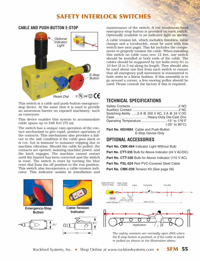
Rockford Systems, Inc. ★ Shop Online at www.rockfordsystems.com ★ SFM 55
SAFETY INTERLOCK SWITCHES
CABLE AND PUSH-BUTTON E-STOP
This switch is a cable and push-button emergency-stop device. At the same time it is used to providean awareness barrier on exposed machinery, suchas conveyors.
This device enables this system to accommodatecable spans up to 248 feet (75 m).
The switch has a unique cam operation of the con-tact mechanism to give rapid, positive operation ofthe contacts. This mechanism also provides a fail-ure to the safe condition if the cable goes slack oris cut, but is immune to nuisance tripping due tomachine vibration. Should the cable be pulled, thecontacts are opened, isolating machine power, andthe latch engages. The machine cannot restartuntil the hazard has been corrected and the switchis reset. The switch is reset by turning the bluereset dial from the off position to the run position.This switch also incorporates a cable-tension indi-cator. This indicator assists in installation and
maintenance of the switch. A red mushroom-heademergency-stop button is provided on each switch.Optionally available is an indicator light as shown.
A cable tension kit, which includes thimbles, cableclamps and a turnbuckle, must be used with thisswitch (see next page). This kit includes the compo-nents to properly tension the cable. When installingthis switch on cable runs over 12 feet, one switchshould be installed at both ends of the cable. Thecables should be supported by eye bolts every 61⁄2 to10 feet (2 to 3 m) along its length. They should alsobe used about one foot from each switch to ensurethat all emergency-pull movement is transmitted toboth units in a linear fashion. If this assembly is togo around a corner, a free-moving pulley should beused. Please consult the factory if this is required.
TECHNICAL SPECIFICATIONSSafety Contacts ....................................................2 NOAuxiliary Contact ..................................................2 NCSwitching Ability ......2 A @ 250 V AC, 2 A @ 24 V DCCase ....................................Heavy-Duty Die-Cast ZincOperating Temperature............................-13° to 176°F
(-25° to 80°C)
Part No. 6024884 Cable and Push-ButtonE-Stop Device Only
OPTIONAL ACCESSORIESPart No. CMK-064 Indicator Light Without Bulb
Part No. CTT-335 Bulb for Above Indicator (24 V AC/DC)
Part No. CTT-336 Bulb for Above Indicator (115 V AC)
Part No. FSL-024 Red PVC-Covered Steel Cable
Part No. CMK-039 Tension Kit (See page 56)
Application
The safety contacts are normally open (NO) whenthe E-stop button is pushed, or if the cable is slackor pulled as shown in the illustration above.
TENSIONSLACK
Emergency-StopButton
Cable-TensionIndicator
31⁄3"23⁄4"
75⁄8"
E-StopButton
Reset Dial
OptionalIndicator
Light
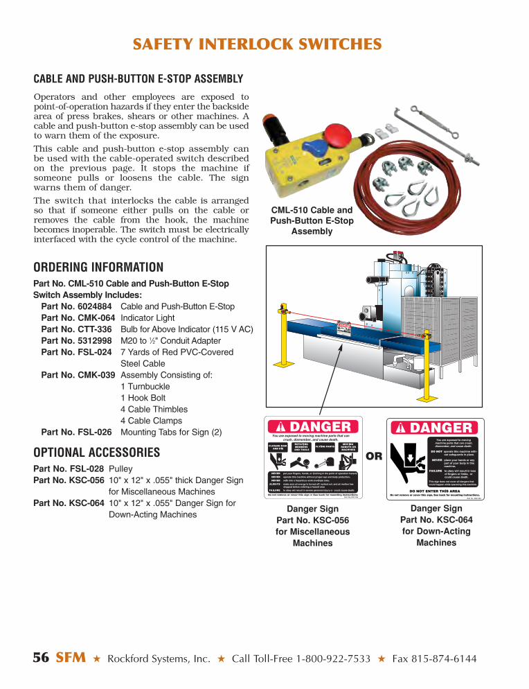
56 SFM ★ Rockford Systems, Inc. ★ Call Toll-Free 1-800-922-7533 ★ Fax 815-874-6144
SAFETY INTERLOCK SWITCHES
CABLE AND PUSH-BUTTON E-STOP ASSEMBLY
Danger Sign Part No. KSC-056 for Miscellaneous
Machines
Operators and other employees are exposed topoint-of-operation hazards if they enter the backsidearea of press brakes, shears or other machines. Acable and push-button e-stop assembly can be usedto warn them of the exposure.
This cable and push-button e-stop assembly canbe used with the cable-operated switch described on the previous page. It stops the machine ifsomeone pulls or loosens the cable. The signwarns them of danger.
The switch that interlocks the cable is arrangedso that if someone either pulls on the cable orremoves the cable from the hook, the machinebecomes inoperable. The switch must be electricallyinterfaced with the cycle control of the machine.
ORDERING INFORMATIONPart No. CML-510 Cable and Push-Button E-StopSwitch Assembly Includes:
Part No. 6024884 Cable and Push-Button E-StopPart No. CMK-064 Indicator LightPart No. CTT-336 Bulb for Above Indicator (115 V AC)Part No. 5312998 M20 to 1⁄2" Conduit Adapter Part No. FSL-024 7 Yards of Red PVC-Covered
Steel Cable Part No. CMK-039 Assembly Consisting of:
1 Turnbuckle1 Hook Bolt4 Cable Thimbles4 Cable Clamps
Part No. FSL-026 Mounting Tabs for Sign (2)
OPTIONAL ACCESSORIESPart No. FSL-028 PulleyPart No. KSC-056 10" x 12" x .055" thick Danger Sign
for Miscellaneous MachinesPart No. KSC-064 10" x 12" x .055" Danger Sign for
Down-Acting Machines Danger Sign
Part No. KSC-064 for Down-Acting
Machines
OR
CML-510 Cable andPush-Button E-Stop
Assembly
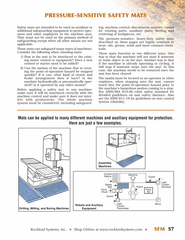
Rockford Systems, Inc. ★ Shop Online at www.rockfordsystems.com ★ SFM 57
PRESSURE-SENSITIVE SAFETY MATS
Safety mats are intended to be used as auxiliary oradditional safeguarding equipment to protect oper-ators and other employees in the machine area.They must not be used as the primary method ofsafeguarding except when all other means are notapplicable.
These mats can safeguard many types of machines.Consider the following when choosing mats:
1) How is the mat to be interfaced to the exist-ing motor control or equipment? Does a newcontrol or starter need to be added?
2) Can the motion of the machine that is creat-ing the point-of-operation hazard be stoppedquickly? If it can, what kind of clutch andbrake arrangement does it have? Is themachine hydraulically or pneumatically oper-ated? Is it operated by any other means?
Before applying a safety mat to any machine,make sure it will be interfaced correctly with themachine control and make sure it does not inter-fere with productivity. The whole machine system must be considered, including safeguard-
ing, machine control, disconnects, starters, coversfor rotating parts, auxiliary parts, feeding andretrieving of workpieces, etc.
The pressure-sensitive, heavy-duty safety matsdescribed on these pages are highly resistant towear, oils, grease, acids and most common chem-icals.
These mats function in two different ways. Oneway is that the machine will not start if someoneor some object is on the mat. Another way is thatif the machine is already operating or cycling, itwill stop if someone steps onto the mat. In thiscase, the machine needs to be restarted once themat has been cleared.
The mat(s) must be located so an operator or otheremployee, when stepping onto the mat, cannotreach into the point-of-operation hazard prior tothe machine’s hazardous motion coming to a stop.See ANSI/RIA R15.06 robot safety standard fordetailed guidelines on mat safety distance. Alsosee the ANSI B11.19 for guidelines on mat controlsystem reliability.
ControlStation
RobotParts
Bin
LightCurtainReceiver
GuardMachine
MirrorLightCurtainTransmitter
SafetyMat
PartsChute
Guard
Mats can be applied to many different machines and auxiliary equipment for protection.Here are just a few examples.
AssemblyMachines
Drilling, Milling, and Boring MachinesRobots and Auxiliary
Equipment
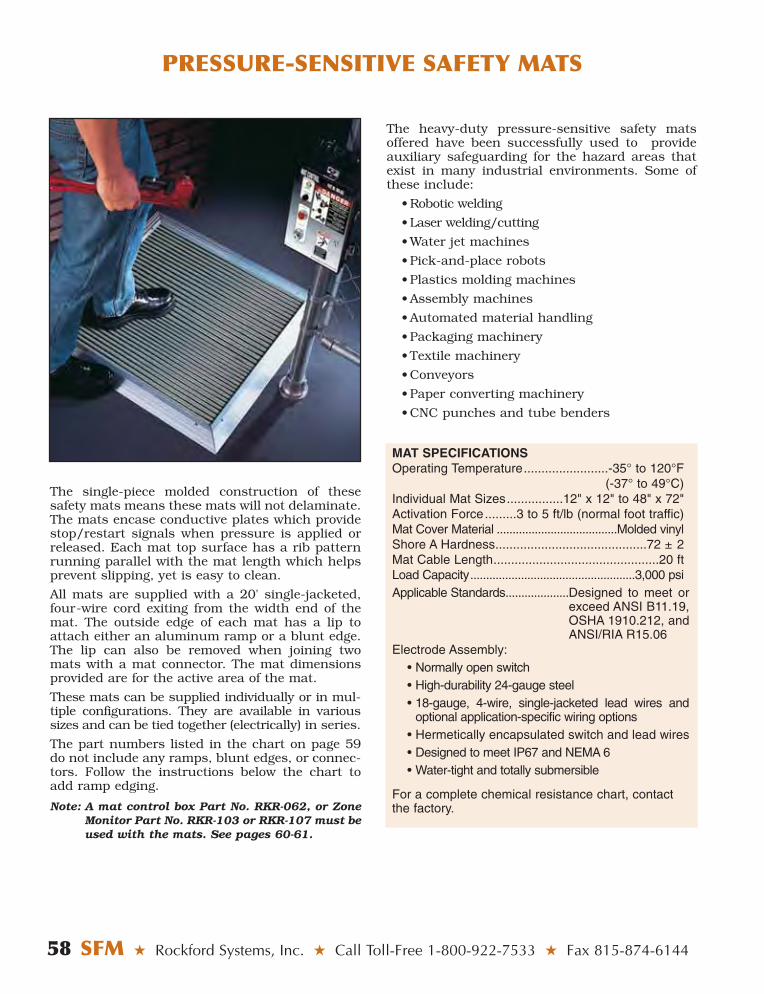
58 SFM ★ Rockford Systems, Inc. ★ Call Toll-Free 1-800-922-7533 ★ Fax 815-874-6144
PRESSURE-SENSITIVE SAFETY MATS
The single-piece molded construction of thesesafety mats means these mats will not delaminate.The mats encase conductive plates which providestop/restart signals when pressure is applied orreleased. Each mat top surface has a rib patternrunning parallel with the mat length which helpsprevent slipping, yet is easy to clean.
All mats are supplied with a 20' single-jacketed,four-wire cord exiting from the width end of themat. The outside edge of each mat has a lip toattach either an aluminum ramp or a blunt edge.The lip can also be removed when joining twomats with a mat connector. The mat dimensionsprovided are for the active area of the mat.
These mats can be supplied individually or in mul-tiple configurations. They are available in varioussizes and can be tied together (electrically) in series.
The part numbers listed in the chart on page 59do not include any ramps, blunt edges, or connec-tors. Follow the instructions below the chart toadd ramp edging.
Note: A mat control box Part No. RKR-062, or ZoneMonitor Part No. RKR-103 or RKR-107 must beused with the mats. See pages 60-61.
MAT SPECIFICATIONSOperating Temperature........................-35° to 120°F
(-37° to 49°C)Individual Mat Sizes................12" x 12" to 48" x 72" Activation Force.........3 to 5 ft/lb (normal foot traffic)Mat Cover Material ......................................Molded vinylShore A Hardness...........................................72 ± 2 Mat Cable Length...............................................20 ft Load Capacity....................................................3,000 psiApplicable Standards....................Designed to meet or
exceed ANSI B11.19,OSHA 1910.212, andANSI/RIA R15.06
Electrode Assembly:• Normally open switch• High-durability 24-gauge steel• 18-gauge, 4-wire, single-jacketed lead wires and
optional application-specific wiring options• Hermetically encapsulated switch and lead wires• Designed to meet IP67 and NEMA 6• Water-tight and totally submersible
For a complete chemical resistance chart, contactthe factory.
The heavy-duty pressure-sensitive safety matsoffered have been successfully used to provideauxiliary safeguarding for the hazard areas thatexist in many industrial environments. Some ofthese include:
• Robotic welding
• Laser welding/cutting
• Water jet machines
• Pick-and-place robots
• Plastics molding machines
• Assembly machines
• Automated material handling
• Packaging machinery
• Textile machinery
• Conveyors
• Paper converting machinery
• CNC punches and tube benders
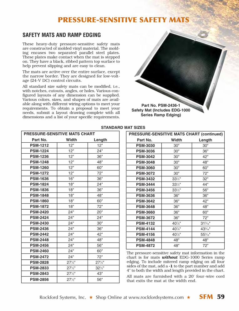
Rockford Systems, Inc. ★ Shop Online at www.rockfordsystems.com ★ SFM 59
SAFETY MATS AND RAMP EDGINGThese heavy-duty pressure-sensitive safety matsare constructed of molded vinyl material. The mold-ing encases two separated parallel steel plates.These plates make contact when the mat is steppedon. They have a black, ribbed pattern top surface tohelp prevent slipping and are easy to clean.
The mats are active over the entire surface, exceptthe narrow border. They are designed for low-volt-age (24-V DC) control circuits.
All standard size safety mats can be modified, i.e.,with notches, cutouts, angles, or holes. Various con-figured layouts of any dimension can be supplied.Various colors, sizes, and shapes of mats are avail-able along with different wiring options to meet yourrequirements. To obtain a proposal to meet yourneeds, submit a layout drawing complete with alldimensions and a list of your specific requirements.
Part No. PSM-2436-1Safety Mat (Includes EDG-1000
Series Ramp Edging)
STANDARD MAT SIZES
PRESSURE-SENSITIVE MATS CHART
Part No. Width LengthPSM-1212 12" 12"PSM-1224 12" 24"PSM-1236 12" 36"PSM-1248 12" 48"PSM-1260 12" 60"PSM-1272 12" 72"PSM-1636 16" 36"PSM-1824 18" 24"PSM-1836 18" 36"PSM-1848 18" 48"PSM-1860 18" 60"PSM-1872 18" 72"PSM-2420 24" 20"PSM-2424 24" 24"PSM-2430 24" 30"PSM-2436 24" 36"PSM-2442 24" 42"PSM-2448 24" 48"PSM-2456 24" 56"PSM-2460 24" 60"
PSM-2472 24" 72"PSM-2828 271⁄2" 271⁄2"PSM-2833 271⁄2" 321⁄2"PSM-2843 271⁄2" 43"
PSM-2856 271⁄2" 56"
PRESSURE-SENSITIVE MATS CHART (continued)
Part No. Width LengthPSM-3030 30" 30"PSM-3036 30" 36"PSM-3042 30" 42"PSM-3048 30" 48"PSM-3060 30" 60"PSM-3072 30" 72"PSM-3432 331⁄2" 32"PSM-3444 331⁄2" 44"PSM-3456 331⁄2" 56"PSM-3636 36" 36"PSM-3642 36" 42"PSM-3648 36" 48"PSM-3660 36" 60"PSM-3672 36" 72"PSM-4132 407⁄8" 313⁄16"PSM-4144 407⁄8" 433⁄16"PSM-4156 407⁄8" 553⁄16"PSM-4848 48" 48"PSM-4872 48" 72”
The pressure-sensitive safety mat information in thechart is for mats without EDG-1000 Series rampedging. To include mitered ramp edging on all foursides of the mat, add a -1 to the part number and add4" to both the width and length provided in the chart.
All mats are furnished with a 20' four-wire cordthat exits the mat at the width end.
PRESSURE-SENSITIVE SAFETY MATS
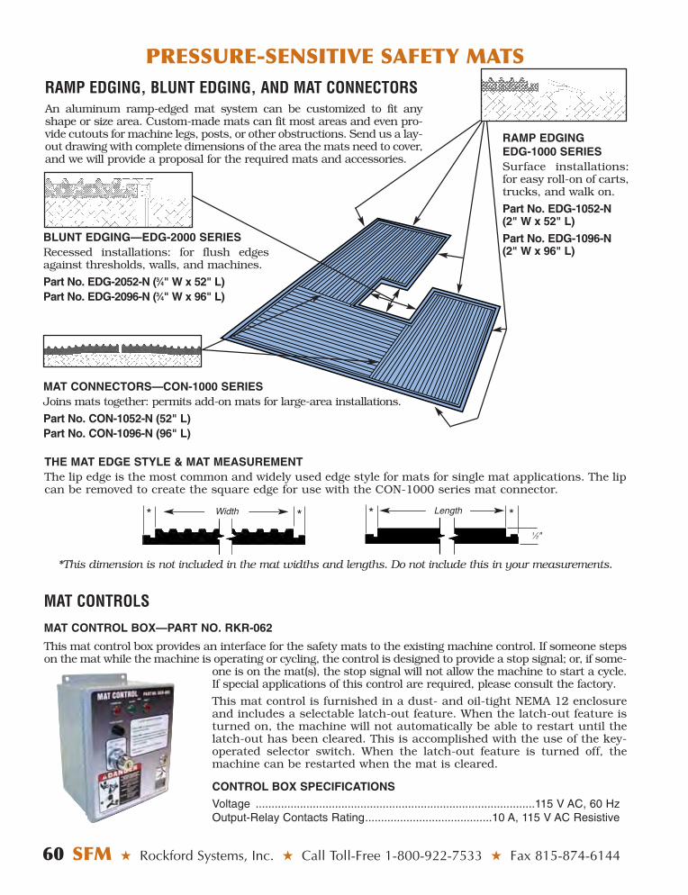
PRESSURE-SENSITIVE SAFETY MATS
60 SFM ★ Rockford Systems, Inc. ★ Call Toll-Free 1-800-922-7533 ★ Fax 815-874-6144
RAMP EDGING, BLUNT EDGING, AND MAT CONNECTORSAn aluminum ramp-edged mat system can be customized to fit anyshape or size area. Custom-made mats can fit most areas and even pro-vide cutouts for machine legs, posts, or other obstructions. Send us a lay-out drawing with complete dimensions of the area the mats need to cover,and we will provide a proposal for the required mats and accessories.
MAT CONNECTORS—CON-1000 SERIESJoins mats together: permits add-on mats for large-area installations.
Part No. CON-1052-N (52" L)Part No. CON-1096-N (96" L)
BLUNT EDGING—EDG-2000 SERIESRecessed installations: for flush edgesagainst thresholds, walls, and machines.
Part No. EDG-2052-N (3⁄4" W x 52" L)Part No. EDG-2096-N (3⁄4" W x 96" L)
RAMP EDGINGEDG-1000 SERIESSurface installations:for easy roll-on of carts,trucks, and walk on.
Part No. EDG-1052-N(2" W x 52" L)
Part No. EDG-1096-N(2" W x 96" L)
THE MAT EDGE STYLE & MAT MEASUREMENTThe lip edge is the most common and widely used edge style for mats for single mat applications. The lipcan be removed to create the square edge for use with the CON-1000 series mat connector.
* * * *
*This dimension is not included in the mat widths and lengths. Do not include this in your measurements.
Width Length
1⁄2"
MAT CONTROLS
MAT CONTROL BOX—PART NO. RKR-062
This mat control box provides an interface for the safety mats to the existing machine control. If someone stepson the mat while the machine is operating or cycling, the control is designed to provide a stop signal; or, if some-
one is on the mat(s), the stop signal will not allow the machine to start a cycle.If special applications of this control are required, please consult the factory.
This mat control is furnished in a dust- and oil-tight NEMA 12 enclosureand includes a selectable latch-out feature. When the latch-out feature isturned on, the machine will not automatically be able to restart until thelatch-out has been cleared. This is accomplished with the use of the key-operated selector switch. When the latch-out feature is turned off, themachine can be restarted when the mat is cleared.
CONTROL BOX SPECIFICATIONS
Voltage ........................................................................................115 V AC, 60 HzOutput-Relay Contacts Rating........................................10 A, 115 V AC Resistive
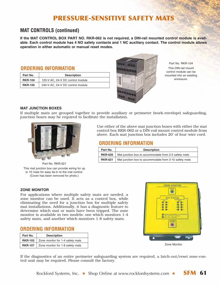
Rockford Systems, Inc. ★ Shop Online at www.rockfordsystems.com ★ SFM 61
If the MAT CONTROL BOX PART NO. RKR-062 is not required, a DIN-rail mounted control module is avail-able. Each control module has 4 NO safety contacts and 1 NC auxiliary contact. The control module allowsoperation in either automatic or manual reset modes.
Part No. RKR-104
This DIN-rail mount control module can be
mounted into an existing enclosure.
PRESSURE-SENSITIVE SAFETY MATS
MAT CONTROLS (continued)
Part No. Description
RKR-104 120-V AC, 24-V DC control module
RKR-105 240-V AC, 24-V DC control module
ORDERING INFORMATION
MAT JUNCTION BOXESIf multiple mats are grouped together to provide auxiliary or perimeter (work-envelope) safeguarding,junction boxes may be required to facilitate the installation.
Use either of the above mat junction boxes with either the matcontrol box RKR-062 or a DIN-rail mount control module fromabove. Each mat junction box includes 20' of four-wire cord.
ZONE MONITORFor applications where multiple safety mats are needed, azone monitor can be used. It acts as a control box, whileeliminating the need for a junction box for multiple safetymat installations. Additionally, it has a diagnostic feature todetermine which mat or mats have been tripped. The zonemonitor is available in two models: one which monitors 1-4safety mats, and another which monitors 1-8 safety mats.
If the diagnostics of an entire perimeter safeguarding system are required, a latch-out/reset zone-con-trol unit may be required. Please consult the factory.
Part No. Description
RKR-020 Mat junction box to accommodate from 2-5 safety mats
RKR-021 Mat junction box to accommodate from 2-10 safety mats
ORDERING INFORMATION
Part No. Description
RKR-103 Zone monitor for 1-4 safety mats
RKR-107 Zone monitor for 1-8 safety mats
ORDERING INFORMATION
Part No. RKR-021
This mat junction box can provide wiring for upto 10 mats for easy tie-in to the mat control.
(Cover has been removed for photo.)
Zone Monitor
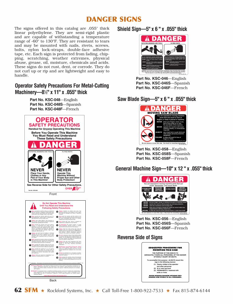
62 SFM ★ Rockford Systems, Inc. ★ Call Toll-Free 1-800-922-7533 ★ Fax 815-874-6144
DANGER SIGNS The signs offered in this catalog are .055" thicklinear polyethylene. They are semi-rigid plasticand are capable of withstanding a temperaturerange of -60° to 130°F. They are resistant to tearsand may be mounted with nails, rivets, screws,bolts, nylon lock-straps, double-face adhesivetape, etc. Each sign is protected from fading, chip-ping, scratching, weather extremes, physicalabuse, grease, oil, moisture, chemicals and acids.These signs do not rust, dent, or corrode. They donot curl up or rip and are lightweight and easy tohandle.
Operator Safety Precautions For Metal-CuttingMachinery—81⁄2" x 11" x .055" thick
Part No. KSC-048—EnglishPart No. KSC-048S—SpanishPart No. KSC-048F—French
Front
Back
Part No. KSC-046—EnglishPart No. KSC-046S—SpanishPart No. KSC-046F—French
Shield Sign—5" x 6 " x .055" thick
Part No. KSC-058—EnglishPart No. KSC-058S—SpanishPart No. KSC-058F—French
Part No. KSC-056—EnglishPart No. KSC-056S—SpanishPart No. KSC-056F—French
Saw Blade Sign—5" x 6 " x .055" thick
General Machine Sign—10" x 12 " x .055" thick
Reverse Side of Signs

Rockford Systems, Inc. ★ Shop Online at www.rockfordsystems.com ★ SFM 63
SURVEY FOR CUTTING AND TURNING MACHINES
Company AddressCity, State, Zip AttentionTelephone No. Date RepresentativeFax No. Surveyed By
When filling out this form, be sure the information is filled in for satisfying the basic areas of safety.Basic Areas—1. Safeguarding 2. Control 3. Disconnect 4. Starter 5. Cover 6. Other Considerations
For identification and reference, please fill in this area first. Machine No.__________________ Dept._____________________Manufacturer________________________________ Model No.______________________ Serial No.___________________
INSTALLATION ■ N ■ Y Is machine presently out of service? ■ N ■ Y
4620 Hydraulic RoadRockford, IL 61109-2695Toll-Free 1-800-922-7533Phone 815-874-7891Fax 815-874-6144
NO.(Proposal Sequence Reference)
1. Safeguarding: ■ Has ■ Provide ■ Contact Manufacturer
■ Drill: ■ Press ■ Gang: No. of Heads:_________ ■ Radial ■ Other____________Is a drill shield required? ■ N ■ Y
If Y, what style? (circle one) Aluminum–Telescoping–Chip: Sm. or Lg.–Universal–FlexibleIf aluminum: Is front hinge required? ■ N ■ Y If Y, ■ 2-Tier: Sm or Lg ■ 3-Tier
Is side hinge required? ■ N ■ Y If Y, ■ 2-Tier ■ 3-TierIf telescoping: (check one) ■ 2-Tier ■ 3-Tier ■ Quill Dia._____" ■ Lug TypeIf universal:
What is the arm length? (circle one) 21" 31" 44"What style is required? (circle one) Sm. 30° Lg. 30° 90° 30°/90° Sm. Flat Lg. Flat Sm. Concave Lg. Concave
If flexible: What is the arm length? (circle one) 12" 18" 24" What style? DM MB What size shield?(circle one) 6" x 8" 10" x 12" (circle one)
■ Lathe: ■ Engine ■ Turret ■ VTL ■ Other_________________________Is a lathe chuck shield required? ■ N ■ Y
If Y, what is the chuck diameter when jaws are extended?______________________"Style: (circle one) Transparent Steel: Sm or Lg. Sliding
Is a mounting bracket required? (required with transparent and small steel) ■ N ■ YIf Y, what type? (circle one) A A1 B B2
Is an electrical interlocking bracket assembly required? ■ N ■ YIs a spring-loaded chuck wrench required? ■ N ■ Y
If Y, what size________"? What style? Standard Longer What shape? Square HexIs a crosslide-travel shield required? ■ N ■ Y
If Y, what model? (circle one) Small LargeAre supplemental shields required? ■ N ■ Y
If Y, what style(s)?______________________________________________________
■ Mill: ■ Vertical ■ Horizontal ■ Jig ■ Bridge Size: ■ Small ■ Med. ■ LargeIs a milling machine shield required? ■ N ■ Y
If Y, what style?(circle one) Slide/Swing Aside–Bridgeport–Chip: Sm. or Lg.–Universal–FlexibleIf slide and swing aside:
What is the length of the bed?______" Are rear shields required? ■ N ■ YIs an electrical interlocking bracket assembly required? ■ N ■ Y
If Bridgeport: (circle one) Front Shield Rear ShieldIf universal or flexible: See drill section above.If chip: See drill section above.
Are supplemental shields required? ■ N ■ YIf Y, what style(s)?______________________________________________________
Are Bridgeport belt covers required? ■ N ■ Y (Model J)
■ Grinder: ■ Bench/Pedestal ■ Surface ■ OD ■ ID ■ Other________________Is a grinder shield required? ■ N ■ Y
If Y, what style? ■ Double-Wheel Shield (6" x 18") ■ Single-Wheel Shield (6" x 6")■ Pivot Mount (6" x 63⁄8") ■ Standard Mount: 61⁄4" x 51⁄4" 81⁄2" x 6" 123⁄4" x 12"Quantity_________________ (circle size)
1(circle style and shape)

64 SFM ★ Rockford Systems, Inc. ★ Call Toll-Free 1-800-922-7533 ★ Fax 815-874-6144
SURVEY FOR CUTTING AND TURNING MACHINES ■ Saw: ■ Table ■ Cutoff ■ Radial Arm ■ Band ■ Other____________Is a shield for a saw required? ■ N ■ Y If Y, use other machine specs for furnishing shield.
■ Other: ■ Borer ■ Broach ■ Planer ■ Machining Center ■ Other________________Is a free-standing shield required? ■ N ■ Y
If Y, what size? ■ 48" x 48" ■ 48" x 60" ■ 48" x 72" ■ 48" x 96"Is a magnetic-base shield required? ■ N ■ Y
If Y, what size? ■ Small Flat ■ Medium Flat ■ Large Flat ■ Small Concave ■ Large Concave ■ With Arm Extension
Is a special shield or guard required? ■ N ■ Y If Y, what style?_________________
2. Control:A. Is a transformer for 115-V power supply required? ■ N/A ■ N ■ YB. Is a red emergency-stop button or cable required? ■ N ■ Y
If Y, check one: ■ Small Button W/Twist Reset ■ Large Button With Latch & Mntg. Box■ Cable & Switch Assembly PLUS ■ KSC-056 Sign
3. Disconnect:A. Is an electrical disconnect switch required? ■ N ■ Y If Y, furnish HP, FLA and
Voltage in 4A.B. How is the disconnect to be furnished (if required)? ■ Separate ■ Combo W/Starter C. Plug lockout? ■ N/A ■ N ■ YD. Air lockout valve? ■ N/A ■ N ■ Y If Y: (circle one) 1⁄4" 1⁄2" 3⁄4"
4. Starter:A. Is a magnetic motor starter required? ■ N ■ Y
If Y provide:_______ Horsepower _______ RPM_______ Full-Load Amps _______ Voltage_______ Hz ■ 1 Phase ■ 3 Phase
B. How is starter to be furnished (if required)? ■ Separate ■ Combo W/DisconnectC. What type of main drive starter is required? Nonreversing ■ N ■ Y Reversing ■ N ■ YD. Is a remote push-button station required? ■ N ■ YE. Is the motor two-speed? ■ N ■ Y If Y, provide motor nameplate data.F. Is the motor jogged or reversed frequently? ■ N ■ Y
5. Cover:Do any mechanical power-transmission apparatuses need to be covered up to 7 feet above floor or platform? ■ N ■ Y If Y, what needs to be covered?
Gears ■ N ■ Y Leadscrew ■ N ■ Y Pulley and Belts ■ N ■ YSprockets and Chain ■ N ■ Y Horizontal Shaft ■ N ■ Y Other_________________Shaft End ■ N ■ Y Vertical Shaft ■ N ■ Y
6. Other Considerations:A. Does the shield require an electrical interlock switch? ■ N/A ■ N ■ Y
Is a mounting bracket required? ■ N ■ YB. Does the interlock require a timer or stop-motion detector? ■ N/A ■ N ■ Y
If Y: ■ Timer ■ Stop-Motion Detector PLUS ■ Proximity Switch SetC. Is a safety relay required? ■ N ■ Y If Y: ■ 24 V DC ■ 115 V ACD. Is an electrical power cutoff system w/chain required? ■ N/A ■ N ■ YE. Is an electronic motor brake required? ■ N ■ Y
If Y, be sure that all of 4A is completed.Start-Up Time_____sec Coastdown Time_____sec No. of Braking Stops/Hr______Does the electronic motor brake require: ■ Zero-Speed Sensing ■ Extended Braking Time ■ Mechanical Brake Release■ High Brake Torque ■ Other __________________
Does the machine have:■ Manual Brake ■ Variable-Speed Drive ■ Forward/Reversing Starter■ Single-Speed Motor ■ High-Inertia Loads ■ Mechanical-Holding Brake
F. Are danger signs required? ■ N ■ Y
5
6
4
3
2
1

Rockford Systems, Inc. ★ Shop Online at www.rockfordsystems.com ★ SFM 65
OSHA 29 CFR 1910.212 and a portion of 1910.219are included in this catalog for use as a referencewhen determining safety requirements for bringingcutting and turning machines into compliance.Please note that 29 CFR 1910.147 (lockout/tagout)is not included here but it is an OSHA standard anemployer must comply with for all machines andequipment.
29 CFR 1910.212 GENERAL REQUIRE-MENTS FOR ALL MACHINES.
(a) Machine guarding — (1) Types of guarding. One ormore methods of machine guarding shall be provided toprotect the operator and other employees in themachine area from hazards such as those created bypoint of operation, ingoing nip points, rotating parts, fly-ing chips and sparks. Examples of guarding methodsare - barrier guards, two-hand tripping devices, elec-tronic safety devices, etc.
(2) General requirements for machine guards. Guardsshall be affixed to the machine where possible andsecured elsewhere if for any reason attachment to themachine is not possible. The guard shall be such that itdoes not offer an accident hazard in itself.
(3) Point of operation guarding. (i) Point of operationis the area on the machine where work is actually per-formed upon the material being processed.
(ii) The point of operation of machines whose opera-tion exposes an employee to injury, shall be guarded.The guarding device shall be in conformity with anyappropriate standards therefor; or, in the absence ofapplicable specific standards, shall be so designed andconstructed as to prevent the operator from having anypart of his body in the danger zone during the operatingcycle.
(iii) Special hand tools for placing and removingmaterial shall be such as to permit easy handling ofmaterial without the operator placing a hand in thedanger zone. Such tools shall not be in lieu of otherguarding required by this section, but can only be usedto supplement protection provided.
(iv) The following are some of the machines whichusually require point-of-operation guarding:
(a) Guillotine cutters.(b) Shears.(c) Alligator shears.(d) Power presses.(e) Milling machines.(f) Power saws.(g) Jointers.(h) Portable power tools.(i) Forming rolls and calenders.
(4) Barrels, containers, and drums. Revolving drums,barrels and containers shall be guarded by an enclo-sure which is interlocked with the drive mechanism, sothat the barrel, drum or container cannot revolveunless the guard enclosure is in place.
(5) Exposure of blades. When the periphery of theblades of a fan is less than seven (7) feet above the flooror working level, the blades shall be guarded. The guardshall have openings no larger then one-half (1⁄2) inch.
(b) Anchoring fixed machinery. Machines designedfor a fixed location shall be securely anchored to pre-vent walking or moving.
29 CFR 1910.219 MECHANICAL POWER-TRANSMISSION APPARATUS.
(b) Prime-mover guards—(1) Flywheels. Flywheelslocated so that any part is seven (7) feet or less abovefloor or platform shall be guarded in accordance withthe requirements of this subparagraph:
(i) With an enclosure of sheet, perforated, or expandedmetal, or woven wire;
(ii) With guard rails placed not less than fifteen (15)inches nor more than twenty (20) inches from rim.When flywheel extends into pit or is within 12 inches offloor, a standard toeboard shall also be provided;
(iii) When the upper rim of flywheel protrudesthrough a working floor, it shall be entirely enclosed orsurrounded by a guardrail and toeboard.
(iv) For flywheels with smooth rims five (5) feet orless in diameter, where the preceding methods cannotbe applied, the following may be used: a disk attachedto the flywheel in such manner as to cover the spokesof the wheel on the exposed side and present a smoothsurface and edge, at the same time providing means forperiodic inspection. An open space, not exceeding four (4)inches in width, may be left between the outside edge ofthe disk and the rim of the wheel if desired, to facilitateturning the wheel over. Where a disk is used, the keysor other dangerous projections not covered by diskshall be cut off or covered. This subdivision does notapply to flywheels with solid web centers.
(v) Adjustable guard to be used for starting engine orfor running adjustment may be provided at the flywheelof gas or oil engines. A slot opening for jack bar will bepermitted.
(vi) Wherever flywheels are above working areas,guards shall be installed having sufficient strength tohold the weight of the flywheel in the event of a shaft orwheel mounting failure.Note: This is not the entire content of 29 CFR 1910.219.
This catalog does not cover all aspects of a safety program. There are many publications on the subject ofsafety. Please see page 5 for a listing of safety sources.
OSHA STANDARDS FOR CUTTING AND TURNING MACHINES
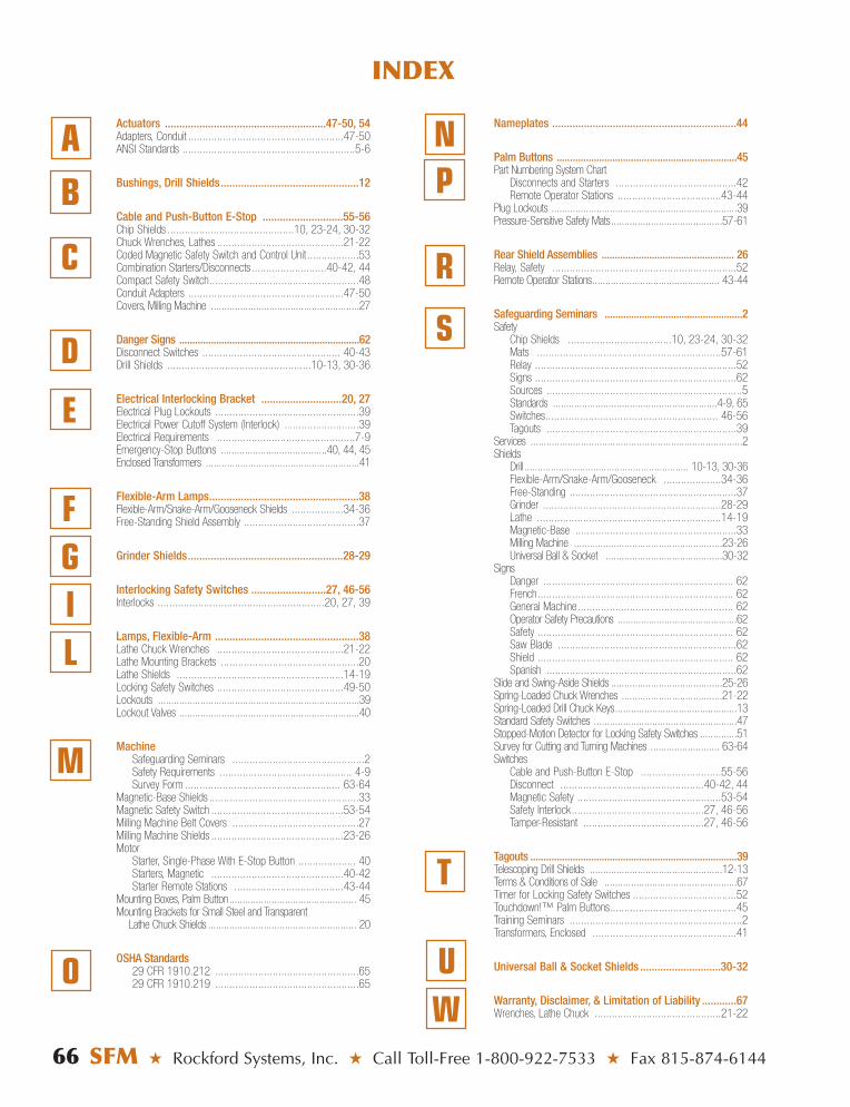
66 SFM ★ Rockford Systems, Inc. ★ Call Toll-Free 1-800-922-7533 ★ Fax 815-874-6144
INDEX
D
E
FGIL
M
O
A
C
Actuators ........................................................47-50, 54Adapters, Conduit ......................................................47-50ANSI Standards ............................................................5-6
Bushings, Drill Shields................................................12
Cable and Push-Button E-Stop ............................55-56Chip Shields ............................................10, 23-24, 30-32Chuck Wrenches, Lathes ............................................21-22Coded Magnetic Safety Switch and Control Unit ..................53Combination Starters/Disconnects ..........................40-42, 44Compact Safety Switch....................................................48Conduit Adapters ......................................................47-50Covers, Milling Machine ........................................................27
Danger Signs ....................................................................62Disconnect Switches ................................................ 40-43Drill Shields ..................................................10-13, 30-36
Electrical Interlocking Bracket ............................20, 27Electrical Plug Lockouts ..................................................39Electrical Power Cutoff System (Interlock) ..........................39Electrical Requirements ................................................7-9Emergency-Stop Buttons ........................................40, 44, 45Enclosed Transformers ..........................................................41
Flexible-Arm Lamps....................................................38Flexible-Arm/Snake-Arm/Gooseneck Shields ..................34-36Free-Standing Shield Assembly ........................................37
Grinder Shields......................................................28-29
Interlocking Safety Switches ..........................27, 46-56Interlocks ..........................................................20, 27, 39
Lamps, Flexible-Arm ..................................................38Lathe Chuck Wrenches ............................................21-22Lathe Mounting Brackets ................................................20Lathe Shields ..........................................................14-19Locking Safety Switches ............................................49-50Lockouts ............................................................................39Lockout Valves ....................................................................40
MachineSafeguarding Seminars ..............................................2Safety Requirements .............................................. 4-9Survey Form ...................................................... 63-64
Magnetic-Base Shields ....................................................33Magnetic Safety Switch ..............................................53-54Milling Machine Belt Covers ............................................27Milling Machine Shields ..............................................23-26Motor
Starter, Single-Phase With E-Stop Button .................... 40Starters, Magnetic ..............................................40-42Starter Remote Stations ......................................43-44
Mounting Boxes, Palm Button................................................ 45Mounting Brackets for Small Steel and Transparent
Lathe Chuck Shields ........................................................ 20
OSHA Standards29 CFR 1910.212 ..................................................6529 CFR 1910.219 ..................................................65
Nameplates ................................................................44
Palm Buttons ....................................................................45Part Numbering System Chart
Disconnects and Starters ..........................................42Remote Operator Stations ....................................43-44
Plug Lockouts ......................................................................39Pressure-Sensitive Safety Mats..........................................57-61
Rear Shield Assemblies .................................................. 26Relay, Safety ................................................................52Remote Operator Stations................................................ 43-44
Safeguarding Seminars ....................................................2Safety
Chip Shields ....................................10, 23-24, 30-32Mats ................................................................57-61Relay ......................................................................52Signs ......................................................................62Sources ....................................................................5Standards ..............................................................4-9, 65Switches............................................................ 46-56Tagouts ..................................................................39
Services ................................................................................2Shields
Drill.............................................................. 10-13, 30-36Flexible-Arm/Snake-Arm/Gooseneck ....................34-36Free-Standing ..........................................................37Grinder ..............................................................28-29Lathe ................................................................14-19Magnetic-Base ........................................................33Milling Machine ........................................................23-26Universal Ball & Socket ............................................30-32
SignsDanger .................................................................. 62French.................................................................... 62General Machine...................................................... 62Operator Safety Precautions ..............................................62Safety .................................................................... 62Saw Blade ..............................................................62Shield .................................................................... 62Spanish ..................................................................62
Slide and Swing-Aside Shields ..........................................25-26Spring-Loaded Chuck Wrenches ......................................21-22Spring-Loaded Drill Chuck Keys..............................................13Standard Safety Switches ......................................................47Stopped-Motion Detector for Locking Safety Switches ..............51Survey for Cutting and Turning Machines .......................... 63-64Switches
Cable and Push-Button E-Stop ............................55-56Disconnect ..................................................40-42, 44Magnetic Safety ..................................................53-54Safety Interlock..............................................27, 46-56Tamper-Resistant ..........................................27, 46-56
Tagouts ..............................................................................39Telescoping Drill Shields ..................................................12-13Terms & Conditions of Sale ..................................................67Timer for Locking Safety Switches ....................................52Touchdown!™ Palm Buttons............................................45Training Seminars ............................................................2Transformers, Enclosed ..................................................41
Universal Ball & Socket Shields ............................30-32
Warranty, Disclaimer, & Limitation of Liability ............67Wrenches, Lathe Chuck ............................................21-22
N
R
S
T
W
PB
U

Rockford Systems, Inc. ★ Shop Online at www.rockfordsystems.com ★ [email protected] ★ SFM 67
TERMS & CONDITIONS OF SALEPRICES A. Prices are subject to change without notice and will be invoiced at the price in effect at
the time of shipment. Unless otherwise stated, all prices are in U.S. dollars.B. Prices specified include no federal, state, local, use, occupational, foreign, or other
tax. Taxes, if applicable, will be added to the invoice.
C. The prices specified include our regular packaging only. Any special packagingrequested by the customer, including special protection for export shipment, willbe at the customer’s expense, and the cost of such special packaging shall be inaddition to the prices quoted.
PAYMENT TERMS Net in 30 days for equipment and net in 10 days for installation, service, and machinesurveys (with approved credit). Machine safeguarding seminar fees are due at the timeof service. A 11⁄2% monthly service charge (18% a year) will be added to past-dueaccounts.
CREDIT POLICY Customers with established credit may purchase for immediate processing of orders.Customers not previously established with us or suitably rated by D&B must apply for open-account status. Orders received without suitable credit information must beprepaid in full before shipment. MasterCard, Visa, and American Express credit cardsare accepted.
MINIMUM ORDER Our minimum order is $25.00. Orders received for less than $25.00 will be subject toa service charge to bring the total to $25.00.
CANCELLATION FEE Orders that are canceled prior to shipment may be subject to a cancellation fee if theproducts are nonstock, custom, special, or built to order.
SHIPPING AND HANDLING Parcels are normally shipped prepaid via our carrier of choice with the charges addedto the invoice, but they can also be sent collect or via consignee billing against the cus-tomer’s account. Truck shipments are normally shipped collect, but they can also beshipped prepaid with the charges added to the invoice via our carrier of choice. A han-dling charge will be added to all invoices except for customer-pickup orders.
INSURANCE All shipments are insured for the standard amount provided by the carrier. Additionalinsurance may be purchased at the customer’s expense.
RISK OF LOSS Unless otherwise agreed upon, all equipment will be shipped FOB shipping point. Titleand risk of loss will pass to the customer upon delivery to the carrier at the point ofshipment. Transportation will be at the customer’s risk and expense, and any claimfor loss or damage in transit must be made directly against the carrier.
RETURNED MERCHANDISE Returned merchandise must be authorized by Rockford Systems in advance, at whichtime an RMA (return materials authorization) number will be issued. No returnedmerchandise will be accepted unless accompanied by an RMA number and thisRMA number plainly identified on the outside of the shipping container. Materialreturned without this RMA number will be refused by our receiving department. Allreturned shipments must be prepaid. The minimum restocking charge will be 25% forany material not found to be defective. Such merchandise must be in original conditionand unused in order to qualify for credit. Custom, special, or built-to-order items maynot qualify for any credit; however, they may be returned for modification, if needed,which may be at an additional cost. No returns for credit will be considered more than30 days from the date of shipment.
WARRANTY Rockford Systems, Inc., warrants that this product will be free from defects in materialand workmanship for a period of 12 months from the date of shipment thereof. ROCK-FORD SYSTEMS INC.’S OBLIGATION UNDER THIS WARRANTY IS EXPRESSLY ANDEXCLUSIVELY LIMITED to repairing or replacing such products which are returned toit within the warranty period with shipping charges prepaid and which will be disclosedas defective upon examination by Rockford Systems, Inc. This warranty will not apply toany product which will have been subject to misuse, negligence, accident, restriction,and use not in accordance with Rockford Systems, Inc.’s instructions or which will havebeen altered or repaired by persons other than the authorized agent or employees ofRockford Systems, Inc. Rockford Systems, Inc.’s warranties as to any component part isexpressly limited to that of the manufacturer of the component part.
DISCLAIMER The foregoing warranty is made in lieu of all other warranties, expressed or implied,and of all other liabilities and obligations on the part of Rockford Systems, Inc.,including any liability for negligence, strict liability, or otherwise, and any implied war-ranty of merchantability or fitness for a particular purpose is expressly disclaimed.
LIMITATION OF LIABILITY Under no circumstances, including any claim of negligence, strict liability or other-wise, will Rockford Systems, Inc., be liable for any incidental or consequential dam-ages, or any loss or damage resulting from a defect in the product of RockfordSystems, Inc.

Catalog FAB
Features products and services for updating fabricating
machines.
Provides details on ourmonthly machine
safeguarding seminar.
Catalog SEM
SFM/TR15M/91407
Shop online at www.rockfordsystems.com
Features a complete line of diesafety blocks and accessories for
use whenever dies are beingadjusted or repaired.
Catalog DSB
Features products for coveringgears, sprockets and chains,conveyors, pulleys and belts,
shaft ends, and more!
Catalog CVR