Embed Size (px)
Citation preview
M. A. Elsayed
D. W. Dareing
C. A. Dupuy
Mechanical Engineering Department, University of Souttiwestern Louisiana,
P.O. Box 44170, Lafayette, LA, 70504-4170
Effect of Downhole Assembly and Polycrystalline Diamond Compact (PDC) Bit Geometry on Stability of Drijlstrings Stability of drillstrings equipped with PDC bits depends on many factors such as the design of the drillstring, design of the bit, and formation type. In this paper, we show that the drill pipe plays a minor role in stability in comparison with that of the drill collars. We also show that the number of bit blades affects the location of the stability pockets, while their spacing affects the size of these pockets. Using this data, a combination of drill collar and bit design can be used to provide operating speeds resulting in maximum stability of the drillstring.
Background
Vibrations in drillstrings cause premature failure of the bit and the joints. They also reduce penetration rate and increase footage cost. The causes of vibration, and particularly their dependence on drillstring and bit design, have been the subject of intensive research.
There are many types of vibration encountered in drillstrings. They can be divided broadly into two categories, namely forced and self-excited vibration. The primary criterion to differentiate between these two types is their response to a change in speed. Whereas the frequency of forced vibration varies with speed, variation in the frequency of self-excited vibrations is generally limited (Elsayed et al., 1995).
An example of forced vibration is the three-cycle-per-revolu-tion oscillation generally detected in drillstrings equipped with a three-cone rotary bit (Dareing and Livesay, 1968). Another example is bit whirl, which exists in conjunction with both the rotary and drag-type bits (Brett et al., 1990). Self-excited vibration, also referred to as chatter, is primarily found in drill-strings equipped with drag bits. In this paper, we limit our discussion to the latter type as applied to drag bits equipped with polycrystalline diamond compact (PDC) cutters.
Self-excited vibration (chatter) is based on the regeneration of waviness on the formation surface. A vibrating system causes the tool to move in a direction perpendicular to the cut surface. This movement creates surface undulations (waviness). This leads to variation in the thickness of the material removed, which results in variation in the cutting force. This, in turn, leads to vibration. If the vibration dies out over time, the system is stable. If it increases, the system is unstable. At the limit of stability, vibration amplitude remains unchanged. Determining this limit of stability for different systems is a subject of intensive research. This is because operation below this limit eliminates self-excited vibration.
Self-excited vibration takes place in the longitudinal, torsional, and lateral directions. Since the force depends on the material thickness, which is affected mostly by longitudinal vibration, torsion was shown to have a minor effect on stability (Elsayed and Dareing, 1994). Lateral vibration was found to have a more substantial effect on stability, but it is mostly dependent on the lateral dynamics, including lateral support, of
Contributed by the Petroleum Division for publication in the JOURNAL OF ENERGY RE,SOURCES TECHNOLOGY. Manuscript received by the Petroleum Division, February 29, 1996; revised manuscript received May 21, 1997. Technical Editor; J. P. Brill.
the drillstring (Dvorak, 1995). In the analysis presented here, we will concentrate on longitudinal vibrations as the primary source of instability.
For our analysis in this paper, we will model a typical drill-string equipped with a PDC bit. A drillstring is typically composed of a short lower section of heavy pipe directly above the bit, referred to as drill collars, attached to a smaller and longer pipe which travels to the surface. The purpose of the drill collars is to provide sufficient weight on the bit for efficient drilling. Since the drillstring is suspended at the top, its lower portion is under compression, while the upper part is under tension. One of the design criteria of the drill collars is for the point of the zero force between the foregoing two regions to fall within the drill collars. Since, generally, the location of this point shifts axially during drilling, it was found that ensuring its presence within the drill collars leads to a reduction in joint failure. In the analysis that follows, it will be shown that the drill collars play a more critical role in stability in comparison with that of the drill pipe. This is because drill collars have a major impact on the location and size of the stability pockets. These pockets are regions of very high stability, and provide the operating speeds where self-excited vibration is eliminated for a wide range of bit diameters.
Drag bit geometry also affects stability. Using a simplified model of the bit in which all the cutting blades are planar, we show that an increase in the number of blades lowers the stability limit, and shifts the stability pockets towards lower speeds. We will also show that uneven spacing between blades causes changes in the stability diagram that may be used to advantage, such as increasing the size of the stability pocket in a desired speed range.
Drillstring Model A drillstring having the following dimensions and compo
nents was selected. The following model is a modified version of the one used by Dareing et al. (1990):
Drill pipe size 0.114 m (4.5 in.) length 2195 m (7200 ft)
Drill collars size 0.165 m (6.5 in.) length 238 m (780 ft)
Traveling block, swivel, kelly 9010 kg (19,800 1b)
Journal of Energy Resources Technology SEPTEMBER 1997, Vol. 119/159
Copyright © 1997 by ASME
Downloaded From: http://energyresources.asmedigitalcollection.asme.org/ on 05/08/2014 Terms of Use: http://asme.org/terms
1.0E-06 R E ft L
5.BE-07
T F
e.BE^ee
-5 .BE-07
-1 .0E-06
: ; 1 1
i i i i
A/ I i 12,13 i / 3 1 i \ \
1 J 2 1 1 1 1
1 j 1 1 j
B.0 4 . 0 8 . 0 1 2 . 0 FBEQUENCV Hz
1 6 . 0 2 0 . 0
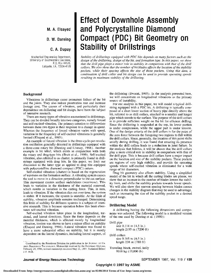
Fig. 1 Real transfer function of drilistring; 238-m drill collars, 2195-m drill pipe
Drawworks stiffness 9.3 E6N/m (52,500 lb/in.)
The model used for analysis was created by replacing the foregoing system with lumped masses attached in series with springs. The drill pipe is divided into 19 sections each with a mass of 2555 kg and a stiffness of 4.94 E6 N/m. The drill collars are divided into 8 sections each with a mass of 4467 kg and a stiffness of 1.24 E8 N/m.
The resulting mass and stiffness distribution is as follows: nti = 10,288 kg, ma - mig = 2555 kg, m2o = 3,511 kg at the interface between the drill pipe and drill collar, m2i - ma? = 4467 kg and the mass attached to the bit is Wag = 2234 kg. The stiffness associated with these masses are: ^ i = 9.3 E6 N/m, K2 - K20 = 4.94 E6 N/m, K2, - K2S = 1.24 E8 N/m.
Mode Shapes and Natural Frequencies
Modal analysis techniques were used to obtain the 28 mode shapes and natural frequencies. The transfer function G = Z/ F, where Z and F are the longitudinal displacement and force at the bit, respectively, was calculated. The real and imaginary components, Re(G) and Im(G), were plotted against the frequency and the relative contribution of various modes evaluated.
Figure 1 shows the Re(G) plot for the drilistring in the 0 to 20 Hz range with an assumed modal damping ^ = 0.04. The dominant modes 1, 2, 3, 12, 13, and 22 with frequencies of 0.35, 1.25, 2.29, 10.10, 10.57, and 19.80 Hz, respectively, are noted.
frequency. To find the speed corresponding to that frequency, we use the following equations (Dareing et al , 1990):
and
e, = 2(7r - ATN (Re(G)/Im(G)))
e/360 + N^'f/iqn}
( 2 )
( 3 )
where e is the phase angle between successive undulations (shown in Fig. 2), e/ is its value at the limit of stability, and n is the speed in rev/s. Here e is kept below 360 deg by introducing an integer A' where A = 0, 1, 2, . . . etc. Various values of A' correspond to different lobes in the stability diagram. In these equations the bit is assumed to have equally spaced planar radial blades.
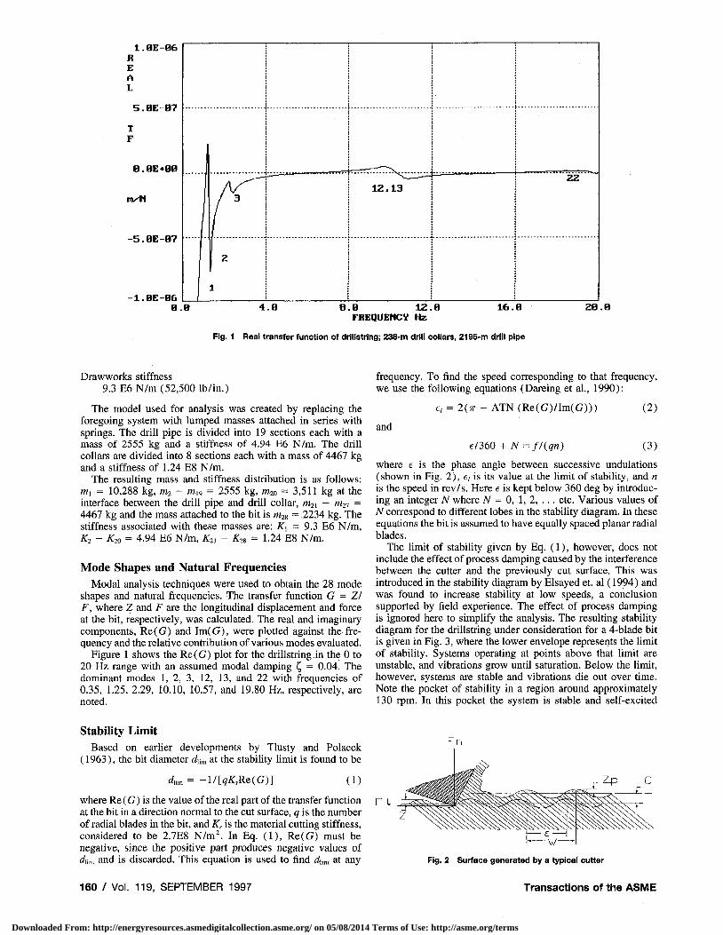
The limit of stability given by Eq. (1), however, does not include the effect of process damping caused by the interference between the cutter and the previously cut surface. This was introduced in the stability diagram by Elsayed et. al (1994) and was found to increase stability at low speeds, a conclusion supported by field experience. The effect of process damping is ignored here to simplify the analysis. The resulting stabiUty diagram for the drilistring under consideration for a 4-blade bit is given in Fig. 3, where the lower envelope represents the limit of StabiUty. Systems operating at points above that limit are unstable, and vibrations grow until saturation. Below the limit, however, systems are stable and vibrations die out over time. Note the pocket of stability in a region around approximately 130 rpm. In this pocket the system is stable and self-excited
Stability Limit
Based on earUer developments by Tlusty and Polacek (1963), the bit diameter dum at the stability limit is found to be
du^ = - l / [ ^ ^ , R e ( G ) ] (1)
where Re (G) is the value of the real part of the transfer function at the bit in a direction normal to the cut surface, q is the number of radial blades in the bit, and K^ is the material cutting stiffness, considered to be 2.7E8 N/m^ In Eq. (1), Re(G) must be negative, since the positive part produces negative values of (iiin, and is discarded. This equation is used to find rfum at any
160 / Vol. 119, SEPTEMBER 1997
Fig. 2 Surface generated by a typical cutter
Transactions of the ASME
Downloaded From: http://energyresources.asmedigitalcollection.asme.org/ on 05/08/2014 Terms of Use: http://asme.org/terms
SPEED ( r p n )
Fig. 3 Stability diagram for drillstring; 238-in drill collars, 2195-m drill pipe
vibrations are eliminated for a large range of bit diameters. This is the desirable operating speed range for this drillstring.
Effect of the Length of Drill Pipe and Drill Collars on Stability
In order to establish the effect of the length of the drill pipe and drill collars on stability, we compare the stability diagrams of several models. These models are all equipped with 4-blade bits and constructed as follows:
A: 238-m drill collars, 2195 m drill pipe (model used in Fig. 3)) B; 238-m drill collars, 347 m drill pipe C: 119-m drill collars, 347 m drill pipe.
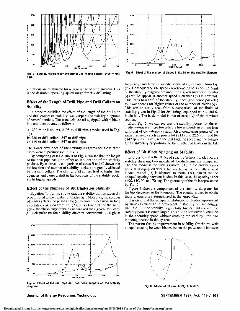
The lower envelopes of the stability diagrams for these three cases were superimposed in Fig. 4.
By comparing cases A and B of Fig. 4, we see that the length of the drill pipe has little effect on the location of the stability
' pockets. By contrast, a comparison of cases B and C shows that the location and number of stability pockets are greatly affected by the drill collars. The shorter drill collars lead to higher frequencies and cause a shift in the locations of the stability pockets to higher speeds.
Effect of the Number of Bit Blades on Stability Equation (1) for ofii, shows that the stability limit is inversely
proportional to the number of blades (q). Moreover, the number of blades affects the phase angle (e) between successive surface undulations as seen from Eq. (3). It is clear that for the same (qn), the phase angle remains unchanged for a given frequency / . Each point on the stability diagram corresponds to a given
25B
B 288 I I
I R H e IBB I E s
n
a
B \ \ H y
\ C
IBB 15B 2eB 2 5 8 SPEED ( r p t i )
Fig. 4 Effect of the drill pipe and drill collar lengths on the stability diagram
Journal of Energy Resources Technology
i
1
1
1 A q
j / \
1 /
-6 /
V_ P6
\ q-l
A / p . ^ I — = i i ^
Fig. 5 Effect of tfie number of blades In the bit on the stability diagram
frequency, and hence a specific value of (c;) as seen from Eq. (2). Consequently, the speed corresponding to a specific point of the stability diagram obtained for a given number of blades (q) would appear at another speed such that (qn) is constant. This leads to a shift of the stability lobes (and hence pockets) to lower speeds for higher values of the number of blades (q). This can be easily seen from a comparison of the limits of stability given in Fig. 5 for drillstrings equipped with 4 and 6-blade bits. The basic model is that of case (A) of the previous section.
From Fig. 5, we can see that the stability pocket for the 6-blade system is shifted towards the lower speeds in comparison with that of the 4-blade system. Also, comparing points of the same frequency such as points P4 (213 rpm, 22.6 mm) and P6 (142 rpm, 15.1 mm), we see that both the speed and the diameter are inversely proportional to the number of blades in the bit.
Effect of Bit Blade Spacing on Stability In order to show the effect of spacing between blades on the
stabihty diagram, two models of the drillstring are compared. The first model is the same as model (A) in the previous sections. It is equipped with a bit which has four equally spaced blades. Model (D) is identical to model (A), except for the unequal spacing between blades. In this case, the spacing is set to 90,110,90, and 70 deg. The geometry of the bit is represented by Fig. 6.
Figure 7 shows a comparison of the stability diagrams for the bits discussed in the foregoing. The equations used to obtain these diagrams are summarized in the Appendix.
It is clear that the unequal distribution of blades represented by limit D causes an improvement in stability on two counts; first, the limit of stability is generally higher, and second, the stability pocket is much larger. This allows for wider fluctuation in the operating speed without crossing the stability limit and inducing chatter in the system.
The reason for the improvement in stability for the bit with unequal spacing between blades, is that the phase angle between
Fig. 6 Model of bit used In Fig. 7, limit D
SEPTEMBER 1997, Vol. 1 1 9 / 1 6 1
Downloaded From: http://energyresources.asmedigitalcollection.asme.org/ on 05/08/2014 Terms of Use: http://asme.org/terms
see
3Be
288
8
V
/ "
/ l"
_ _ ^
ISB SPEED Crpn)
Fig. 7 Effect of bit blade spacing on stability; A: equal spacing, D: unequal spacing
undulations e is no longer equal for any two successive blades. Since stability is strongly dependent on e (Elsayed and Dareing, 1994), the unequal blade spacing breaks the "lock-step" pattern of phase between successive undulations, and in the process, improves stability. This has been observed in practice by Mensa-Wilmot and Alexander (1995).
Other Geometries. One of the problems encountered in drilling is bit whirl (Clayton et al , 1994). Many solutions have been proposed to minimize bit whirl. One of these solutions is to ensure radial balance of the cutting forces. Obviously, the blade distribution shown in Fig, 6 violates this principle. In order to resolve this problem, other designs, in which radial symmetry of the forces as well as uneven blade distribution may be employed. Figure 8 shows such a design.
In this figure, we place a blade in radial symmetry to each blade in Fig. 6. Since, in reality, the bit blades are not planar, blades farther from the center make a larger contribution to the lateral forces causing the bit whirl. A balance of these lateral forces would dictate a shorter outer blade than the inner one it is meant to balance. This pattern is shown in Fig. 8. It is worth noting that this pattern may be repeated radially with a different angular shift between blade sets if desired.
Conclusions As we see from the foregoing analysis, stability of the drill-
string should be considered in the choice of the operating speed for a given bit. Ideally, operation should take place in a stability pocket. This ensures the absence of self-excited vibrations. It is desired that the stability pocket be as large as possible. This ensures stability for a wider range of fluctuation around the desired operating speed. The design of the drill collars is much more critical to the location of these pockets than that of the drill pipe. Also, the locations of the stability pockets depend on the number of blades in the bit. It is found that the speed at a
particular stability pocket is inversely proportional to the number of bit blades. Moreover, the size of the stability pockets can be increased by providing nonuniform spacing between blades. Bit blades can also be placed in sets in a manner that provides uneven spacing between blades and, at the same time, balances the side forces which contribute to bit whirl.
Acknowledgment This work was supported by the National Science Foundation
under Grant No. MSS-9118421.
References Brett, J., Warren, T., and Behr, S., 1990, "Bit Whirl: A New Tlieory of PDC
Bit Failure," SPE Drilling Engineering, pp. 275-281. Clayton, R., and Ivie, B., 1994, "Development of Whirl Resistant PDC Bits,"
SPE Paper 26954, Petroleum Engineering Conference, Buenos Aires, Argentina. Dareing, D., Tlusty, J., and Zamudio, C , 1990, "Self-Excited Vibrations In
duced by Drag Bits," ASME JOURNAL OF ENERGY RESOURCES TECHNOLOGY, Vol. 112, pp. 54-61.
Dareing, D., and Livesay, B., 1968, "Longitudinal and Angular Drillstring Vibrations with damping," Journal Energy Research Technology, Nov., pp. 6 7 1 -679.
Dvorak, D., 1995, "Coupling of Longitudinal and Lateral Vibrations in Drill-strings," a report. University of Florida.
Elsayed, M. A., Wells, R. L., Dareing, D. W., and Nagirimadugu, K., 1994, "Effect of Process Damping on Longitudinal Vibrations in Drillstrings," ASME JOURNAL OF ENERGY RESOURCES TECHNOLOGY, Vol. 116, pp. 129-135.
Elsayed, M. A., and Dareing, D. W., 1994, "Coupling of Longitudinal and Torsional Vibrations in a Single-Mass Model of a Drillstring," Developments in Theoretical and Applied Mechanics, Vol. XVII, Univ. of Arkansas, Fayetteville, AR, pp. 128-139.
Elsayed, M. A., Dareing, D. W., and Vonderheide, M., 1997, "Effect of Torsion on Stability, Dynamic Forces and Vibration Characteristics in Drillstrings," ASME JOURNAL OF ENERGY RESOURCES TECHNOLOGY, Vol. 119, Mar., pp. 1 1 -
19. Mensa-Wilmot G., and Alexander, W., 1995, "New PDC Bit Design Reduces
Vibrations Problems," Oil and Gas Journal, May, pp. 57-59, Tlusty, J., and Polacek, M., 1963, "The Stability of the Machine Tool Against
Self-Excited Vibrations in Machining," ASME Production Engineering Research Conference, Pittsburgh, PA.
Tlusty, J., Dareing, D., and Zamudio, C , 1988, "Progress Report No. 1, Vibrations of Drag Bits," MLI Manufacturing Lab,, Gainsville, Fl,
Zamudio, C, A., Tlusty, and J, L„ Dareing, D, W., 1987, "Self-Excited Vibrations in Drillstrings," SPE Paper 16661, 62nd Annual Conference, Dallas, TX,, pp. 117-123.
A P P E N D I X
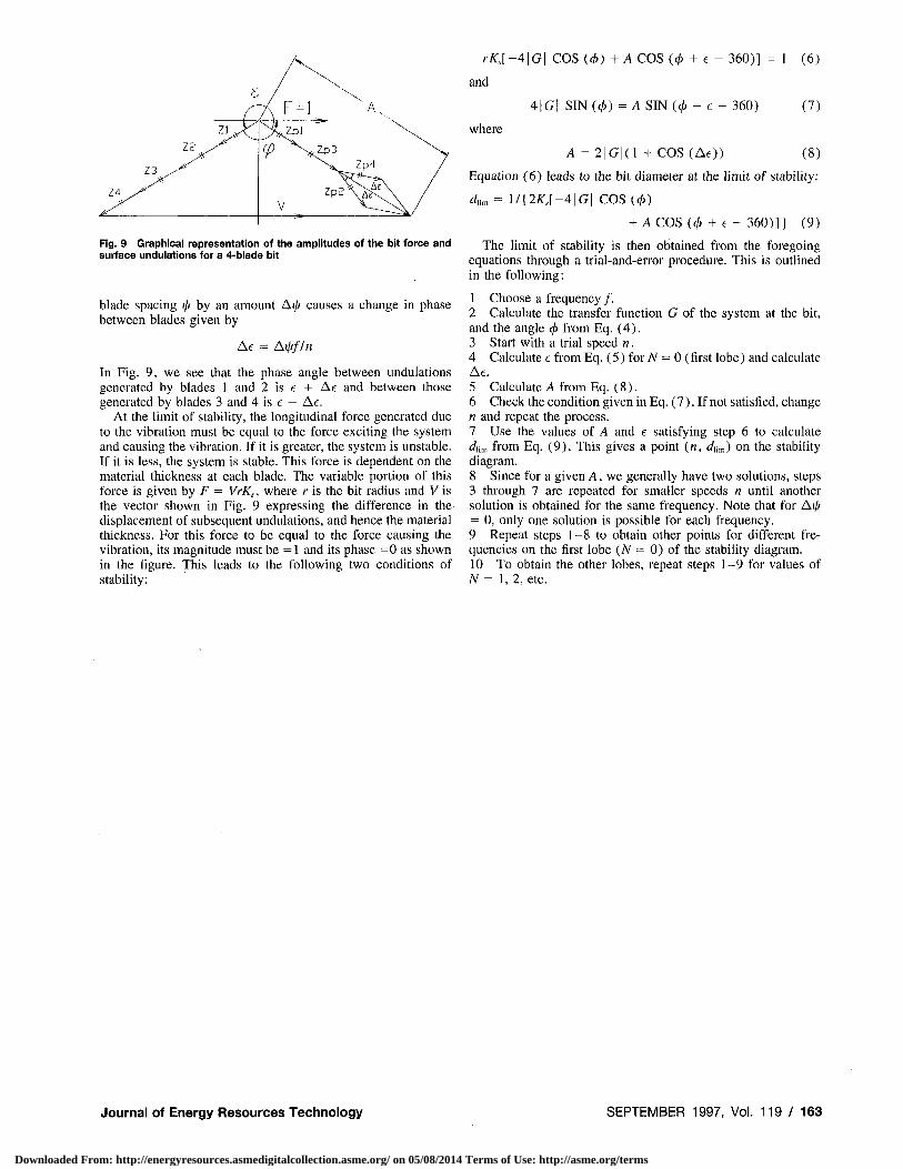
In this appendix, we present the equations used to obtain the limit of stability for a drillstring equipped with a PDC bit with unequal spacing between blades. We will use a 4-blade bit here, but the approach is general. These equations can be easily understood if we use a graphical representation of the force and displacement of the various blades. This representation is shown in Fig. 9 following conventions outlined by Tlusty et al. (1988).
In this figure, the force is assumed to be unity and in the direction shown. In effect, the diagram is drawn with respect to the force, and the amplitude of the displacement of any of the blades \Z\ is equal to that of the transfer function \G\. This is justified, since stability is a function of the ratio G = ZIF. The displacements of the four blades are labeled Z1 through Z 4 (see Fig. 6). These are the amphtudes of the current surface undulations. Those of the previous undulations are labeled Zp\ through ZpA. Since the bit blades are assumed to remain planar, displacements Z 1 , . . . Z4 are in phase and equal in magnitude. The phase angle </> of Z1 , . . . Z4 is given by
(/) = ATN (Im(G)/Re(G)) (4)
Fig. 8 Distribution of blades to balance radial forces
162 / Vol. 119, SEPTEMBER 1997
The phase angle between the surface undulations caused by blades 4 and 1, and blades 2 and 3 (where the spacing is 90 deg) is shown as e and can be obtained from Eq. (3) as follows:
e = ! / ( / / « -360 N (5)
Here i/f = 360/^ and is 90 deg for a 4-blade bit. A shift in the
Transactions of the ASME
Downloaded From: http://energyresources.asmedigitalcollection.asme.org/ on 05/08/2014 Terms of Use: http://asme.org/terms
Z4
Z3
^VvT Z2 , /
A ^ = 1 ^^7^1
^X
V "
^Zp3
ZpP
A„
Zp4
Fig. 9 Graphical representation of tlie amplitudes of the bit force and surface undulations for a 4-blade bit
blade spacing \\i by an amount Ai// causes a change in phase between blades given by
Ae = At////w
In Fig. 9, we see that the phase angle between undulations generated by blades 1 and 2 is e + Ae and between those generated by blades 3 and 4 is e — Ae.
At the limit of stability, the longitudinal force generated due to the vibration must be equal to the force exciting the system and causing the vibration. If it is greater, the system is unstable. If it is less, the system is stable. This force is dependent on the material thickness at each blade. The variable portion of this force is given by F = VrK^, where r is the bit radius and Y is the vector shown in Fig. 9 expressing the difference in the displacement of subsequent undulations, and hence the material thickness. For this force to be equal to the force causing the vibration, its magnitude must be = 1 and its phase =0 as shown in the figure. This leads to the following two conditions of stability:
r^ : , [ -4 |G | COS ((^) + A COS ((^ + e - 360)] = 1 (6)
and
4|Gi SIN((^) = A S I N ( 0 - e - 360) (7)
where
A = 2 |G | (1 + COS (Ae)) (8)
Equation (6) leads to the bit diameter at the limit of stability:
4m = 1/{2KI-4\G\ COS (cj,)
+ A COS(t^ + e - 360)]) (9)
The limit of stability is then obtained from the foregoing equations through a trial-and-error procedure. This is outlined in the following:
1 Choose a frequency / . 2 Calculate the transfer function G of the system at the bit, and the angle (f) from Eq. (4). 3 Start with a trial speed n. 4 Calculate e from Eq. (5) for A? = 0 (first lobe) and calculate Ae. 5 Calculate A from Eq. (8). 6 Check the condition given in Eq. (7). If not satisfied, change n and repeat the process. 7 Use the values of A and e satisfying step 6 to calculate dhm from Eq. (9). This gives a point («, <iii,„) on the stability diagram. 8 Since for a given A, we generally have two solutions, steps 3 through 7 are repeated for smaller speeds n until another solution is obtained for the same frequency. Note that for Ai/* = 0, only one solution is possible for each frequency. 9 Repeat steps 1-8 to obtain other points for different frequencies on the first lobe (N = 0) of the stability diagram. 10 To obtain the other lobes, repeat steps 1-9 for values of N = 1,2, etc.
Journal of Energy Resources Technology SEPTEMBER 1997, Vol. 1 1 9 / 1 6 3
Downloaded From: http://energyresources.asmedigitalcollection.asme.org/ on 05/08/2014 Terms of Use: http://asme.org/terms
![SAM3S8 / SAM3SD8 · 2019. 10. 13. · pioa / piob piodc[7:0] high speed mci datrg pdc pdc pdc pdc pdc pdc pdc pdc pdc pdc pdc pdc pdc dac0 dac1 timer counter 0 tc[0..2] ad[0..14]](https://img.pdfslide.us/doc/110x75/61180b84f50fc135d32d7973/sam3s8-sam3sd8-2019-10-13-pioa-piob-piodc70-high-speed-mci-datrg-pdc.jpg)