Embed Size (px)
Citation preview

EE 435
Lecture 33
• String DAC

Data Converter Design Strategies
Performance Threshold
Remember: Need to keep nonideal effects below an acceptable performance threshold
Review from Last Lecture

Identifying Problems/Challenges and Clever/Viable Solutions• Many problems occur repeatedly so should recognize when they occur
• Identify clever solutions to basic problems – they often are useful in
many applications
• Don’t make the same mistake twice !
The problem:
The perceived solution:
The practical or clever solution:
The List Keeper !
The List !
Reminder !!

The List !
Extra Credit will be given for each entry
Use the Discussion section in Canvas
Each Entry on a First-come basis
Students will be asked to classify all entries near the end of the semester
Reminder !!

The Keeper !
Enter List Entries Here
Format: List Entries : Number (use next number available), Title, Name (Your
name), Description
Be brief but clear in both Title and Description
Reminder !!

R-String DAC
R
S1
R
S2
R
SN-2
R
SN-1
R
SN
VRFF
VOUT
n
XIN
Binary to
Thermometer
Decoder
2n
Basic R-String DAC including Logic to Control Switches
Review from Last Lecture

R-String DACR-String DAC with MOS switches
Switch impedance is not 0
Switch may not even turn on at all if VREF is large
Switch impedance is input-code dependent
Time constants are input-code dependent
Transition times are previous-code dependent
CL has 2n diffusion capacitances so can get very large
Mismatch of resistors
local random variation
gradient effects
Decoder can get very large for n large
Routing of the 2n switch signals can become very long
and consume lots of area
R
M1
R
M2
R
MN-2
R
MN-1
R
MN
VRFF
VOUT
n
XIN
Binary to
Thermometer
Decoder
2n
d1
d2
dN-2
dN-1
dN
CL
Possible Limitations:
(will discuss this issue next)
Review from Last Lecture

R-String DAC
b3 b3 b2 b2 b1 b1
R-String
VREF
XIN
n
Decoder
VOUT
MUX Decoder
Review from Last Lecture

Parasitic Capacitors in MOSFET
Operation Region Dependent and Fixed -- Ohmic
Overlap Capacitors: CGDO, CGSO
Junction Capacitors: CBS1, CBD1
CGDO
CGSO
CBS1 CBD1
Ohmic Capacitor: CGCH , CBCH
CGCH
CBCH
Review from Last Lecture

Parasitic Capacitance SummaryD
S
G B
CGS
CGD
CBS
CBD
CBG
Cutoff Ohmic Saturation
CGS CoxWLD CoxWLD + 0.5COXWL CoxWLD+(2/3)COXWL
CGD CoxWLD CoxWLD + 0.5COXWL CoxWLD
CBG CoxWL (or less) 0 0
CBS CBOTAS+CSWPS CBOTAS+CSWPS+0.5WLCBOTCH CBOTAS+CSWPS +(2/3)WLCBOTCH
CBD CBOTAD+CSWPD CBOTAD+CSWPD+0.5WLCBOTCH CBOTAD+CSWPD
Review from Last Lecture

R-String DAC
b3 b3 b2 b2 b1 b1
R-String
VREF
XIN
n
Decoder
VOUT
MUX Decoder
Tree-Decoder Layout/Architecture
Each intersection is a reserved site for a switch

bm bm
Vk
Uncontacted Row-Column Structure

Row-Column Structure with Contacts Addedbm bm
Vk
..
.
bm bm
Vk
OR
Programmed entirely with the contact mask

R-String DAC
b3 b3 b2 b2 b1 b1
R-String
VREF
XIN
n
Decoder
VOUT
MUX Decoder
Parasitic Capacitances in MUX Decoder

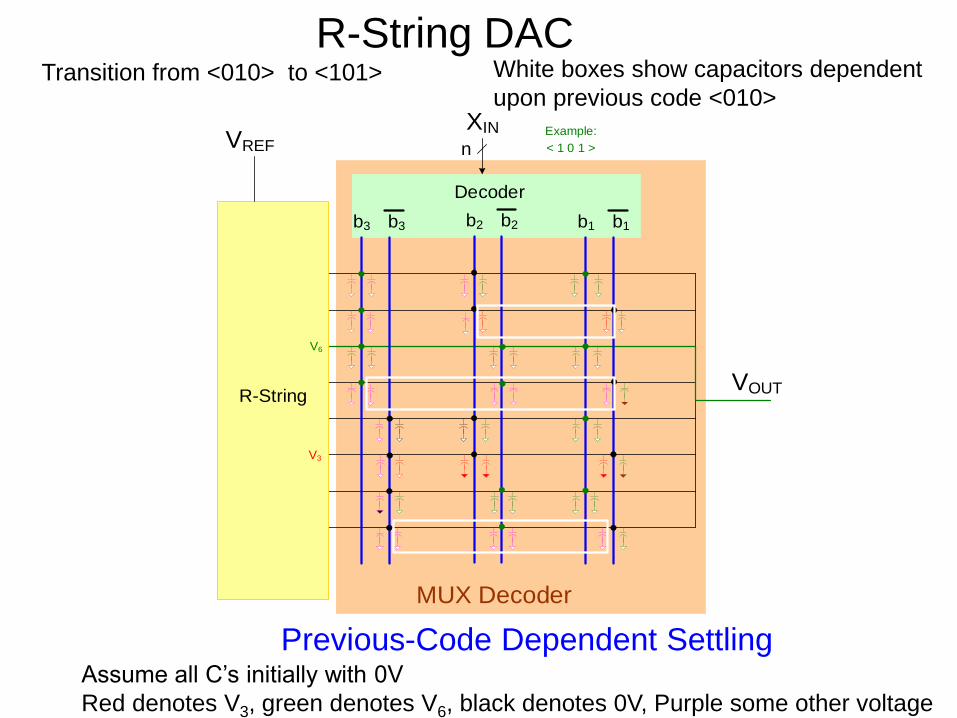
R-String DAC
Previous-Code Dependent Settling
b3 b3 b2 b2 b1 b1
R-String
VREF
XIN
n
Decoder
VOUT
MUX Decoder
< 0 1 0 >
Example:
V3
Assume all C’s initially with 0V
Red denotes V3, black denotes 0V, Purple some other voltage

R-String DAC
Previous-Code Dependent SettlingAssume all C’s initially with 0V
Red denotes V3, green denotes V6, black denotes 0V, Purple some other voltage
b3 b3 b2 b2 b1 b1
R-String
VREF
XIN
n
Decoder
VOUT
MUX Decoder
< 1 0 1 >
Example:
V3
V6
Transition from <010> to <101>
R-String DAC
Previous-Code Dependent SettlingAssume all C’s initially with 0V
Red denotes V3, green denotes V6, black denotes 0V, Purple some other voltage
Transition from <010> to <101>
b3 b3 b2 b2 b1 b1
R-String
VREF
XIN
n
Decoder
VOUT
MUX Decoder
< 1 0 1 >
Example:
V3
V6
White boxes show capacitors dependent
upon previous code <010>

R-String DAC
Tree-Decoder in Digital Domain
b3 b3 b2 b2 b1 b1
Decoder
MUX Decoder
VDDVOUT
Do the resistors that form part of PTL dissipate any substantial power?
No because only one will be conducting for any DAC output
Single transistor used at each marked intersection to form PTL -AND gates

R-String DAC
b1 b1 b2 b2 b3 b3
R-String
VREF
XIN
n
Decoder
VOUT
Tree Decoder
Analog MUX with Tree Decoder


What is the INL performance of this DAC?
ENOB?
What is the spectral performance?
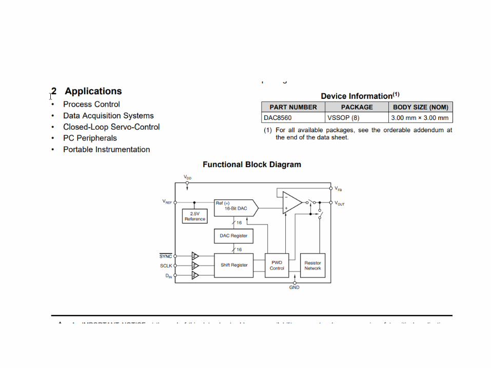
The DAC 8560

R-String DAC
R
R
R
R
VRFFn1
XIN
S1
S2
S3
RF
SN2
n2
n
1 2n = n :n
Sck
Sck
Sc1
R
Sc1
Sc2
Sc2
Sc3
Sc3
ScN1
ScN1
RF
RF
RF
RF
SN2-1
VOUT

R-String DAC
R
R
R
R
VRFFn1
XIN
S1
S2
S3
RF
SN2
VOUT
n2
n
1 2n = n :n
Sck
Sc(k-1)
Sc1
R
Sc2
Sc4
Sc3
ScN1
Sc(N1-1)
RF
RF
RF
RF
SN2-1
SN2+1
Sometimes termed sub-divider,
sub-range or dual-string DAC

Stay Safe and Stay Healthy !

End of Lecture 33