Embed Size (px)
Citation preview
EE 42 and 100, Fall 2005 Week 1 1
Announcements
1. Information you’d like to get from this course. Think of one or more things you’re curious about and would like to learn about in this course. Put them on a blank card I’ll supply. (For example, how does radio work? What is a carbon nanotube and how might one use it?) We’ll try to give you answers.
2. Since people in EE42 are supposed to take P/NP 1-unit EE43 we will not include a lab grade in the EE42 scoring. The new weights for grading in EE42 will be: MT1 22%; MT2 22%; HW 12%; Final 44%.
3. Homeworks – including the first one – will be due at 12:00 noon on Thursdays (not Wednesdays).
4. We’ll add some new lab sections; check the web site.

EE 42 and 100, Fall 2005 Week 1 2
Electric Charge
Definition: The quantity of electricity that flows in a given time or is held in a component such as a capacitor
Symbol: qUnit: Coulomb (C)Notes: Charges may be positive or negative
Like charges (e.g., + and +) repel each other, unlike charges (+ and -) attract each other
EE 42 and 100, Fall 2005 Week 1 3
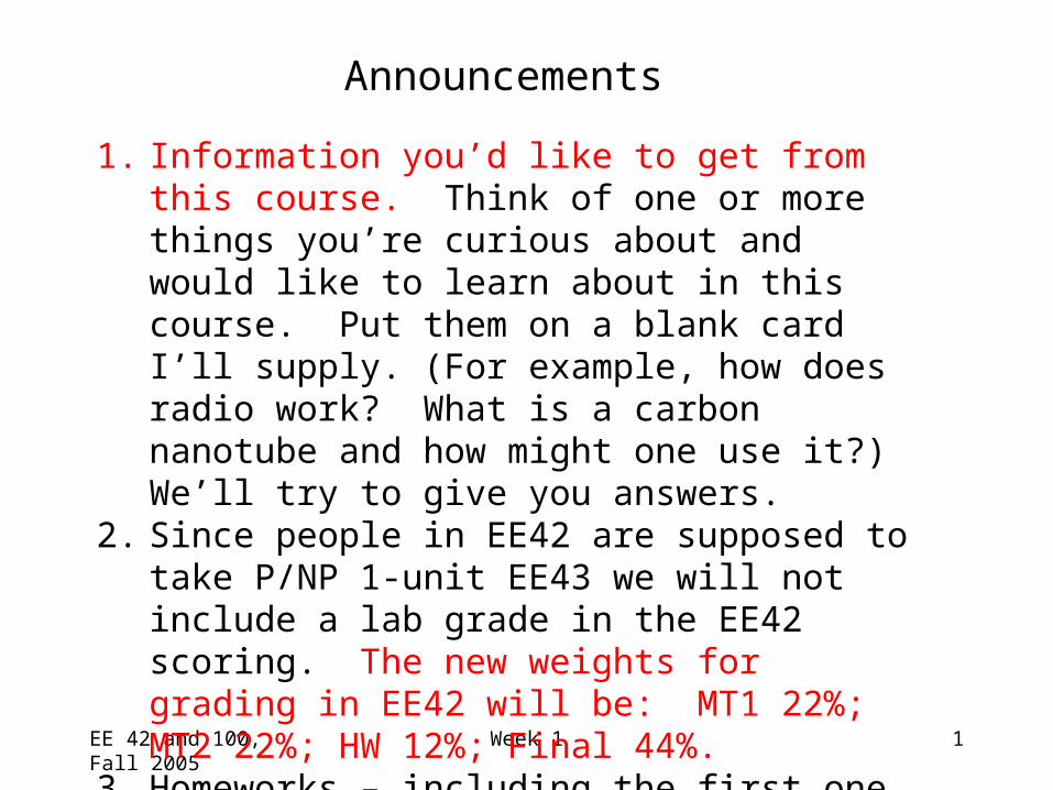
Electric CurrentDefinition: rate of positive charge flowSymbol: iUnits: Coulombs per second ≡ Amperes (A)
i = dq/dt
where q = charge (in Coulombs), t = time (in seconds)
Note: Current has polarity (flow direction).

EE 42 and 100, Fall 2005 Week 1 4
Electric Potential (Voltage)• Definition: energy per unit charge expended in moving a
charge from one place to another
• Symbol: v
• Units: Joules/Coulomb ≡ Volts (V)
v = dw/dq
where w = energy (in Joules), q = charge (in Coulombs)
Note: Potential is always referenced to some point.
Subscript convention:
vab means the potential at a minus the potential at b.
a
b vab ≡ va - vb

EE 42 and 100, Fall 2005 Week 1 5
Electric Power• Definition: amount of energy transferred per unit
time
• Symbol: p
• Units: Joules per second ≡ Watts (W)
p = dw/dt = (dw/dq)(dq/dt) = vi
• Concept:
As a positive charge q moves through a drop in voltage of amount v, it loses energy
energy change = qv rate is proportional to # charges/sec

EE 42 and 100, Fall 2005 Week 1 6
The Ideal Basic Circuit Element
Attributes:• Two terminals (points of connection)• Cannot be subdivided into other elements• Mathematically described by its current-voltage
relationship
+v_
i • Polarity reference for voltage can be indicated by plus and minus signs
• Reference direction for the current is indicated by an arrow
• Examples: resistor, capacitor, inductor, diode, …

EE 42 and 100, Fall 2005 Week 1 7
- v +
A problem like “Find the current” or “Find the voltage” is always accompanied by a definition of the direction:
In this case, if the current turns out to be 1 mA flowing to the left, we would say i = -1 mA. (See prefixes in Hambley, p. 18.)
In order to perform circuit analysis to determine the voltages and currents in an electric circuit, you need to specify reference directions. There is no need to guess the reference direction so that the answers come out positive, however.
A Note about Reference Directions
i

EE 42 and 100, Fall 2005 Week 1 8
Suppose you have an unlabelled battery and you measure its voltage with a digital voltmeter (DVM). It will tell you the magnitude and sign of the voltage.
With this circuit, you are measuring vab.
The DVM indicates 1.401, so va
is lower than vb by 1.401 V.
Which is the positive battery terminal?
1.401
DVM
a
b
Note that we have used the “ground” symbol ( ) for the reference node on the DVM. Often it is labeled “C” for “common.”
Sign Convention Example

EE 42 and 100, Fall 2005 Week 1 9
Sign Convention for Power
• If p > 0, power is being delivered to the gray box. • If p < 0, power is being extracted from the box.
+v_
i
Passive sign convention
_
v+
i
p = vi
+v_
i
_
v+
i
p = -vi

EE 42 and 100, Fall 2005 Week 1 10
Find the power absorbed by each element:
Power Calculation Example
vi (W)918
- 810- 12
- 400- 2241116
p (W)
Conservation of energy total power delivered
equals total power absorbed
Aside: For electronics these are un-realistically large currents – mA is more typical than A (1 mA = 0.001A)
EE 42 and 100, Fall 2005 Week 1 11
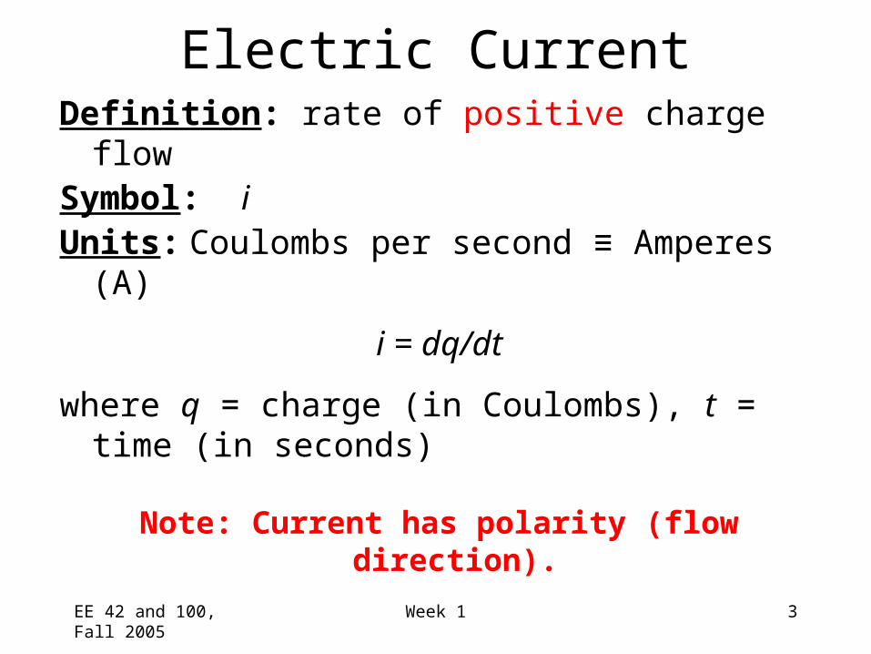
Circuit Elements• 5 ideal basic circuit elements:
– voltage source
– current source
– resistor
– inductor
– capacitor
• Many practical systems can be modeled with just sources and resistors
• The basic analytical techniques for solving circuits with inductors and capacitors are the same as those for resistive circuits
active elements, capable ofgenerating electric energy
passive elements, incapable ofgenerating electric energy
EE 42 and 100, Fall 2005 Week 1 12
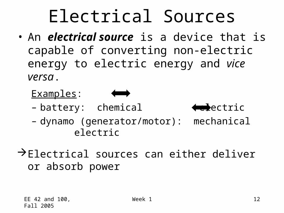
Electrical Sources• An electrical source is a device that is capable of
converting non-electric energy to electric energy and vice versa.
Examples:
– battery: chemical electric
– dynamo (generator/motor): mechanical electric
Electrical sources can either deliver or absorb power

EE 42 and 100, Fall 2005 Week 1 13
Ideal Independent and Dependent Voltage Sources
• Circuit element that maintains a prescribed voltage across its terminals, regardless of the current flowing in those terminals.– Voltage is known, but current is determined by the circuit
to which the source is connected.
• The voltage can be either independent of dependent on a voltage or current elsewhere in the circuit, and can be constant or time-varying.
Circuit symbols:
+ + +_vs_vs=vx
_vs=ix
independent voltage-controlled current-controlled

EE 42 and 100, Fall 2005 Week 1 14
Other Independent Voltage Source Symbols
v(t) = Vpeaksin(t)
(In US, veff = 120 V, soVpeak = 170 V)
Sinusoidal AC source
Battery (realistic source)
+VS
2/peakeffective vv

EE 42 and 100, Fall 2005 Week 1 15EE 42 Lecture 3 14Spring 2005
Realistic Voltage Source A real-life voltage source, like a battery
or the function generator in lab, cannot sustain a very high current. Either a fuse blows to shut off the device, or something melts…
Additionally, the voltage output of a realistic source is not constant. The voltage decreases slightly as the current increases.
We usually model realistic sources considering the second of these two phenomena. A realistic source is modeled by an ideal voltage source in series with an “internal resistance”, RS.
Vs
RS

EE 42 and 100, Fall 2005 Week 1 16
I-V Plot for a Real Battery

EE 42 and 100, Fall 2005 Week 1 17
Ideal Independent and Dependent Current Sources
• Circuit element that maintains a prescribed current through its terminals, regardless of the voltage across those terminals.– Current is known, but voltage is determined by the circuit
to which the source is connected.
• The current can be either independent or dependent on a voltage or current elsewhere in the circuit, and can be constant or time-varying.
Circuit symbols:
is is=vx is=ix
independent voltage-controlled current-controlled

EE 42 and 100, Fall 2005 Week 1 18
Electrical Resistance• Resistance: Electric field is proportional to current
density, within a resistive material. Thus, voltage is proportional to current. The circuit element used to model this behavior is the resistor.
Circuit symbol:
Unit for R: Volts per Ampere ≡ ohms ()
• The current flowing in the resistor is proportional to the voltage across the resistor:
v = i Rwhere v = voltage (V), i = current (A), and R = resistance ()
R
(Ohm’s Law)

EE 42 and 100, Fall 2005 Week 1 19
Water analogies for electrical elements
Since you can’t see electricity, it is useful to think of the flow ofwater as being like that of electric charge. We’ll see wateranalogies for a number of electrical devices – capacitors, diodes,etc.
Water analogy for charge: a quantity of water (say, 1 gallon is like 1 coulomb of charge)Water analogy for current flow: flow rate of water (say, 1 gallon per second is like 1 coulomb per second = 1 ampere)Electric potential difference (voltage) is like the difference in pressure in a hydraulic systemThe model for a resistor (an increased resistance reduces the current that flows for a given voltage) is like the effect of putting a sponge in a water pipe or crimping it
EE 42 and 100, Fall 2005 Week 1 20
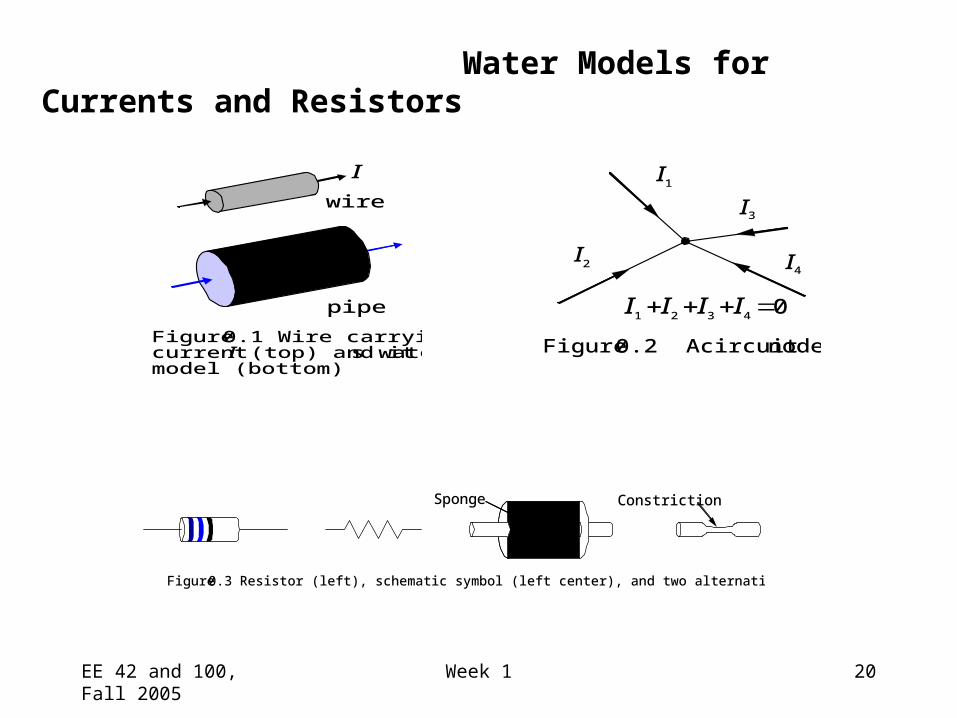
wire
pipe
Figure 0.1 Wire carryingcurrent I (top) and its watermodel (bottom)
I I1
I3
I4I2
I1 I2 I3 I4 0
Figure 0.2 A circuit node
Figure 0.3 Resistor (left), schematic symbol (left center), and two alternative water models (right)
Sponge Constriction
Water Models for Currents and Resistors

EE 42 and 100, Fall 2005 Week 1 21
Resistance of an actual resistor
W
L
T
Material resistivity = (-cm)
Resistance = resistivity x length/(cross-sectional area)
R = (L/WT)

EE 42 and 100, Fall 2005 Week 1 22
Electrical Conductance• Conductance is the reciprocal of resistance.
Symbol: G
Units: siemens (S) or mhos ( )
Example:
Consider an 8 resistor. What is its conductance?

EE 42 and 100, Fall 2005 Week 1 23
Short Circuit and Open CircuitWire (“short circuit”):• R = 0 no voltage difference exists
(all points on the wire are at the same potential)
• Current can flow, as determined by the circuit
Air (“open circuit”):• R = no current flows• Voltage difference can exist, as determined by the circuit

EE 42 and 100, Fall 2005 Week 1 24
Circuit Nodes and Loops• A node is a point where two or more circuit elements
are connected.• A loop is formed by tracing a closed path in a circuit
through selected basic circuit elements without passing through any intermediate node more than once
Example:

EE 42 and 100, Fall 2005 Week 1 25
Kirchhoff’s Laws• Kirchhoff’s Current Law (KCL):
– The algebraic sum of all the currents entering any node in a circuit equals zero. (An expression of the conservation of charge.)
• Kirchhoff’s Voltage Law (KVL):
– The algebraic sum of all the voltages around any loop in a circuit equals zero. (As a result of conservation of energy.)

EE 42 and 100, Fall 2005 Week 1 26
Example: Power Absorbed by a Resistor
p = vi = ( iR )i = i2R
p = vi = v ( v/R ) = v2/R
Note that p > 0 always, for a resistor.
Example:
a) Calculate the voltage vg and current ia.
b) Determine the power dissipated in the 80 resistor.

EE 42 and 100, Fall 2005 Week 1 27
“Lumped Element” Circuit Modeling
(Model = representation of a real system which simplifies analysis)
• In circuit analysis, important characteristics are grouped together in “lumps” (separate circuit elements) connected by perfect conductors (“wires”)
• An electrical system can be modeled by an electric circuit (combination of paths, each containing 1 or more circuit elements) if the dimensions of the circuit are small compared with the wavelength of any electromagnetic waves in the vicinity (i.e., wavelength = c/f >> physical dimensions of system, where c = velocity of EM waves and f = frequency of wave). For example, at 60 Hz, the powerline frequency in the U. S., = 3 x 10⁸ (m/s)/60 (1/s) = 5 x 10⁶ m ~ 3000 miles! so we can do lumped element circuit modeling of ordinary circuits at 60 Hz.

EE 42 and 100, Fall 2005 Week 1 28
Construction of a Circuit Model• The electrical behavior of each physical
component is of primary interest.
• We need to account for undesired as well as desired electrical effects.
• Simplifying assumptions should be made wherever reasonable.
EE 42 and 100, Fall 2005 Week 1 29
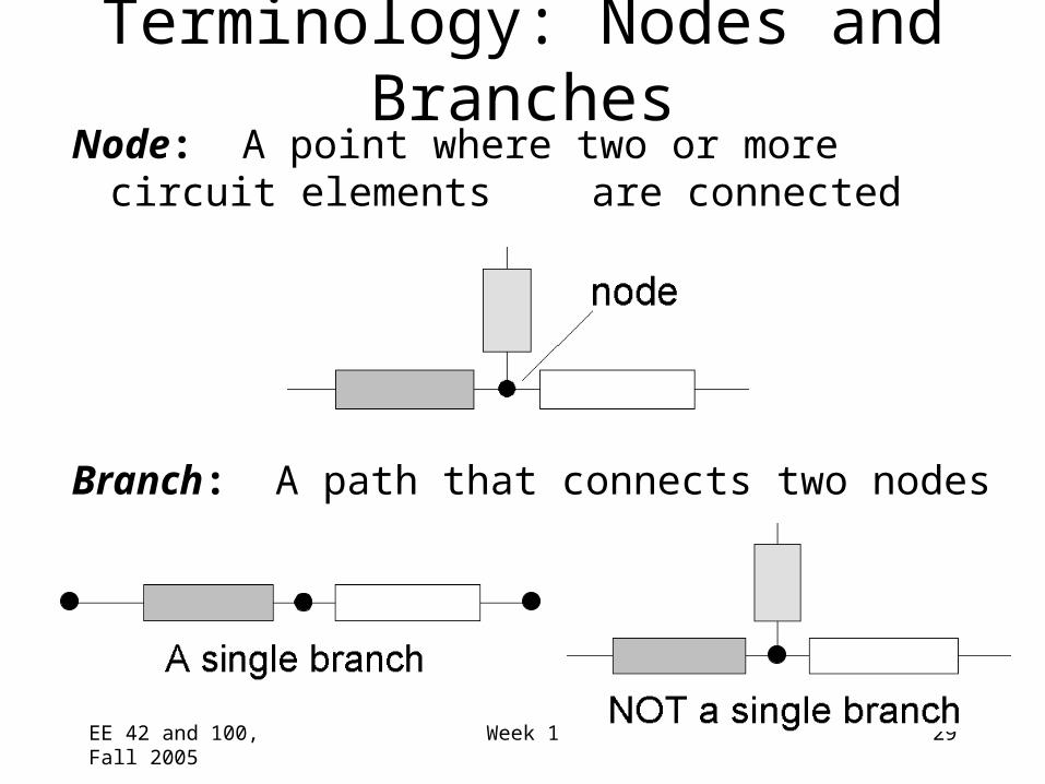
Terminology: Nodes and BranchesNode: A point where two or more circuit elements
are connected
Branch: A path that connects two nodes

EE 42 and 100, Fall 2005 Week 1 30
Notation: Node and Branch Voltages
• Use one node as the reference (the “common” or “ground” node) – label it with a symbol
• The voltage drop from node x to the reference node is called the node voltage vx.
• The voltage across a circuit element is defined as the difference between the node voltages at its terminals
Example:
+_ vs
+va
_
+vb
_
a b
c
R1
R2
– v1 +
REFERENCE NODE

EE 42 and 100, Fall 2005 Week 1 31
• Use reference directions to determine whether currents are “entering” or “leaving” the node – with no concern about actual current directions
Using Kirchhoff’s Current Law (KCL)
i1
i4
i3
i2
Consider a node connecting several branches:
EE 42 and 100, Fall 2005 Week 1 32
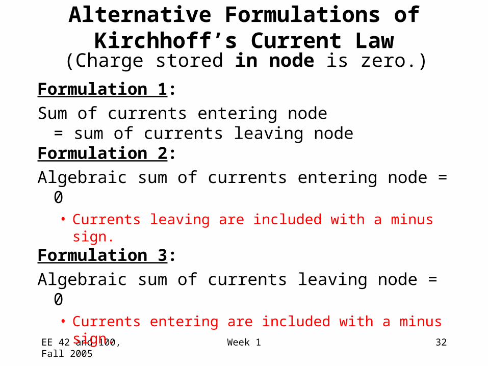
Alternative Formulations of Kirchhoff’s Current Law
Formulation 1:
Sum of currents entering node = sum of currents leaving node
Formulation 2:
Algebraic sum of currents entering node = 0• Currents leaving are included with a minus sign.
Formulation 3:
Algebraic sum of currents leaving node = 0• Currents entering are included with a minus sign.
(Charge stored in node is zero.)

EE 42 and 100, Fall 2005 Week 1 33
EE 42 and 100, Fall 2005 Week 1 34
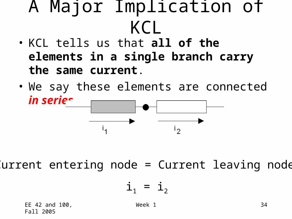
A Major Implication of KCL• KCL tells us that all of the elements in a single
branch carry the same current.• We say these elements are connected in series.
Current entering node = Current leaving node
i1 = i2

EE 42 and 100, Fall 2005 Week 1 35
KCL Example
5 mA
15 mA
i-10 mA
3 formulations of KCL:
1.
2.
3.
Currents entering the node:
Currents leaving the node:

EE 42 and 100, Fall 2005 Week 1 36
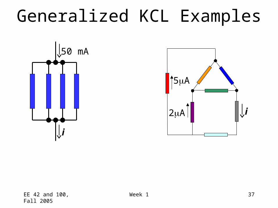
Generalization of KCL• The sum of currents entering/leaving a closed
surface is zero. Circuit branches can be inside this surface, i.e. the surface can enclose more than one node!
This could be a big chunk of a circuit, e.g., a “black box” i1
i2
i3
i4
EE 42 and 100, Fall 2005 Week 1 37
Generalized KCL Examples
5A
2A i
50 mA
i
EE 42 and 100, Fall 2005 Week 1 38
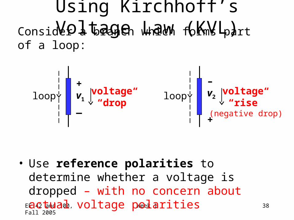
• Use reference polarities to determine whether a voltage is dropped – with no concern about actual voltage polarities
Using Kirchhoff’s Voltage Law (KVL)
Consider a branch which forms part of a loop:
+v1
_loop voltage
“drop”
–v2
+
loop voltage “rise”
(negative drop)

EE 42 and 100, Fall 2005 Week 1 39
Formulations of Kirchhoff’s Voltage Law
Formulation 1:
Sum of voltage drops around loop = sum of voltage rises around loop
Formulation 2:
Algebraic sum of voltage drops around loop = 0• Voltage rises are included with a minus sign.
Formulation 3:
Algebraic sum of voltage rises around loop = 0• Voltage drops are included with a minus sign.
(Conservation of energy)
(Handy trick: Look at the first sign you encounter on each element when tracing the loop.)

EE 42 and 100, Fall 2005 Week 1 40
A Major Implication of KVL• KVL tells us that any set of elements that are
connected at both ends carry the same voltage.• We say these elements are connected in parallel.
Applying KVL in the clockwise direction, starting at the top:
vb – va = 0 vb = va
+va
_
+ vb
_

EE 42 and 100, Fall 2005 Week 1 41
Path 1:
Path 2:
Path 3:
vcva
+
+
3
21
+
vb
v3v2
+
+
-
Three closed paths:
a b c
KVL Example

EE 42 and 100, Fall 2005 Week 1 42
• No time-varying magnetic flux through the loopOtherwise, there would be an induced voltage (Faraday’s Law)
Avoid these loops!
How do we deal with antennas (EECS 117A)?
Include a voltage source as the circuit representation of the induced voltage or “noise”.(Use a lumped circuit model rather than a distributed (wave) model.)
• Note: Antennas are designed to “pick up” electromagnetic waves; “regular circuits” often do so undesirably.
)t(B
)t(v+
An Underlying Assumption of KVL

EE 42 and 100, Fall 2005 Week 1 43
Consider a circuit with multiple resistors connected in series.Find their “equivalent resistance”.
• KCL tells us that the same current (I) flows through every resistor
• KVL tells us
Equivalent resistance of resistors in series is the sum
of the individual resistances
R2
R1
VSS
I
R3
R4
+
Resistors in Series

EE 42 and 100, Fall 2005 Week 1 44
I = VSS / (R1 + R2 + R3 + R4)
Voltage Divider
+– V1
+– V3
R2
R1
VSS
I
R3
R4
+

EE 42 and 100, Fall 2005 Week 1 45
SS4321
22
VRRRR
RV
Correct, if nothing elseis connected to nodes
because R5 removes conditionof resistors in series
SS4321
22
VRRRR
RV
≠
When can the Voltage Divider Formula be Used?
+– V2
R2
R1
VSS
I
R3
R4
+
R2
R1
VSS
I
R3
R4
+
R5
+– V2

EE 42 and 100, Fall 2005 Week 1 46
• KVL tells us that the same voltage is dropped across each resistor
Vx = I1 R1 = I2 R2
• KCL tells us
R2R1 ISS
I2I1
x
Resistors in ParallelConsider a circuit with two resistors connected in parallel.Find their “equivalent resistance”.

EE 42 and 100, Fall 2005 Week 1 47
What single resistance Req is equivalent to three resistors in parallel?
+
V
I
V
+
I
R3R2R1 Req
eq
General Formula for Parallel Resistors
Equivalent conductance of resistors in parallel is the sum

EE 42 and 100, Fall 2005 Week 1 48
ba c
d e
Potential
f
Figure 0.1 Resistor/battery circuits (These illustrations were kindly given to one of the authors by Jim Hauser of San Luis Obispo, CA.)

EE 42 and 100, Fall 2005 Week 1 49
Vx = I1 R1 = ISS Req
Current Divider
R2R1 ISS
I2I1
x

EE 42 and 100, Fall 2005 Week 1 50
R2R1 I
I2I1 I3R3
+
V
321 R1
R1
R1
IV
321
3
33 1/R1/R1/R
1/RI
RV
I
Generalized Current Divider Formula
Consider a current divider circuit with >2 resistors in parallel:
EE 42 and 100, Fall 2005 Week 1 51
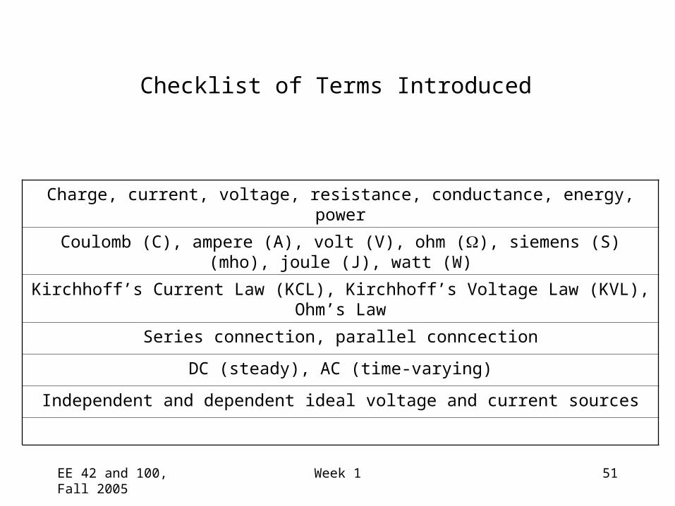
Charge, current, voltage, resistance, conductance, energy, power
Coulomb (C), ampere (A), volt (V), ohm (), siemens (S) (mho), joule (J), watt (W)
Kirchhoff’s Current Law (KCL), Kirchhoff’s Voltage Law (KVL), Ohm’s Law
Series connection, parallel conncection
DC (steady), AC (time-varying)
Independent and dependent ideal voltage and current sources
Checklist of Terms Introduced