Embed Size (px)
Citation preview

ACIMAC
HA
ND
BO
OK
S2011E D I T I O N

© Copyright ACIMAC, Associazione Costruttori Italiani Macchine Attrezzature per Ceramica Via Fossa Buracchione 84 • 41126 Baggiovara (MO) • Italy • Tel. +39 059 510 336 • www.acimac.it
Edito da S.A.L.A. srl • Via Fossa Buracchione 84 • 41126 Baggiovara (MO) • Italy • Tel. +39 059 510 108
In cooperation with:
Date of going to press: September 2011
Euro 10 - IVA assolta dall'editore
ACIMAC
HA
ND
BO
OK
S2011E D I T I O N

2 . Acimac handbooks - 2011 Edition
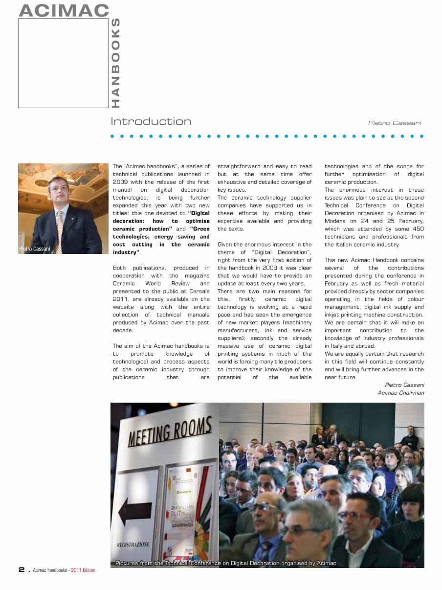
The “Acimac handbooks”, a series of technical publications launched in 2009 with the release of the fi rst manual on digital decoration technologies, is being further expanded this year with two new titles: this one devoted to “Digital decoration: how to optimise ceramic production” and “Green technologies, energy saving and cost cutting in the ceramic industry”.
Both publications, produced in cooperation with the magazine Ceramic World Review and presented to the public at Cersaie 2011, are already available on the website along with the entire collection of technical manuals produced by Acimac over the past decade.
The aim of the Acimac handbooks is to promote knowledge of technological and process aspects of the ceramic industry through publications that are
Introduction Pietro Cassani
straightforward and easy to read but at the same time offer exhaustive and detailed coverage of key issues. The ceramic technology supplier companies have supported us in these efforts by making their expertise available and providing the texts.
Given the enormous interest in the theme of “Digital Decoration”, right from the very fi rst edition of the handbook in 2009 it was clear that we would have to provide an update at least every two years. There are two main reasons for this: fi rstly, ceramic digital technology is evolving at a rapid pace and has seen the emergence of new market players (machinery manufacturers, ink and service suppliers); secondly the already massive use of ceramic digital printing systems in much of the world is forcing many tile producers to improve their knowledge of the potential of the available
technologies and of the scope for further optimisation of digital ceramic production. The enormous interest in these issues was plain to see at the second Technical Conference on Digital Decoration organised by Acimac in Modena on 24 and 25 February, which was attended by some 450 technicians and professionals from the Italian ceramic industry.
This new Acimac Handbook contains several of the contributions presented during the conference in February as well as fresh material provided directly by sector companies operating in the fi elds of colour management, digital ink supply and inkjet printing machine construction. We are certain that it will make an important contribution to the knowledge of industry professionals in Italy and abroad. We are equally certain that research in this fi eld will continue constantly and will bring further advances in the near future.
Pietro CassaniAcimac Chairman
Pietro Cassani
Pictures from the Technical Conference on Digital Decoration organised by AcimacPictures from the Technical Conference on Digital Decoration organised by Acimac
ACIMAC
HA
NB
OO
KS
Acimac handbooks - 2011 Edition . 3
Digital Decoration: how to optimise ceramic production
Colour management
Quality control in ceramic digital printing process: a possible utopia Alessandro Beltrami, In.Te.Sa ...........................................................................................................pag. 4
ColourService, support for digital and conventional printing Colour Service ..............................................................................................................................pag. 10
Visualisation, control, profi ling and colour management tools Marco Sichi, Euromeccanica ..........................................................................................................pag. 14
Inks
Digital decoration: product innovation or process innovation? Renewing the business model Davide Corradini, Colorobbia ..........................................................................................................pag. 18
Pigmented ceramic inks Daniele Verucchi, Maurizio Cavedoni, Inco .......................................................................................pag. 24
Digital glazes for an entirely digital glazing and decoration process Esmalglass-Itaca Grupo ................................................................................................................pag. 30
The new range of Smaltink inks Mirko Marastoni, Smalticeram ......................................................................................................pag. 34
Machinery
Making sense of inkjet technology for ceramic tile decoration Terry O’Keeffe, Bailey Smith, Henrik Lauridsen, Fujifi lm Dimatix ........................................................pag. 36
Inkjet technology in ceramic tile decoration Davide Sorrentino, Mauro Bedini, In.Te.sa ........................................................................................pag. 48
Advantages of digital printing in the ceramic decoration process Alberto Ghisellini, Kerajet Italia ....................................................................................................pag. 56
Innovative solutions for inkjet printing machines Francesco Casoni, Siti B&T - Projecta ...........................................................................................pag. 66
Process innovation, the key to digital technology Paolo Monari, System .................................................................................................................. pag. 72
The development of inkjet technology: fl exibility and productivity Pedro Benito Alcantara, Cretaprint ............................................................................................. pag. 76
Contents

4 . Acimac handbooks - 2011 Edition
Quality control in ceramic digital printing process:
a possible utopiamedia are extensively documented and treated in the fi eld of graphic arts. Even more widely documented are the techniques for industrial colour measurement on ceramic substrates with various surface characteristics. However, to date there has been very little research into characterisation techniques for such varied substrates as ceramic surfaces, which can range from glossy white wall tiles to textured and coloured porcelain tile surfaces.
The measurement of colour as part of a generic set of quality parameters is a non-trivial issue because it is closely related to other parameters involving visual appearance, such as the various types of surface texture (waviness, orange peel, etc.), gloss level and haze. Variations in these parameters have an enormous infl uence on colour perception, which depends on light conditions. Unfortunately, colour measuring instruments (spectrophotometers) behave more selectively and objectively than the human eye, which interprets visual perception
Digital decoration on ceramic surfaces has experienced exponential growth in recent years. As a result, new technical expertise is needed for effective management of a process characterised by a large number of complex variables. The experimental approach adopted by many operators results in a high degree of ineffi ciency in the digital design preparation stage and above all leads to the use of imprecise methods that are incompatible with an industrial process that should be describable and repeatable.
When reproducing a design on a ceramic surface, it is important that the people responsible for creating the digital fi les, for separating them, for performing the test run, production and quality control come to an agreement on a minimum set of parameters that uniquely defi ne the visual and technical characteristics of the digitally decorated ceramic surface. These parameters should be defi ned independently of the digital printing procedure adopted and above all should focus on the fi nished product. Colour measurements on paper
according to the context and the appearance parameters of the observed material. For this reason the search for the “perfect spectrophotometer” is doomed to failure as some of these surface parameters will have to be included or excluded according to the application.
The most effective and effi cient method of quality control for digital printing is to use a testchart that allows multiple parameters to be controlled objectively and subjectively at the same time. The testchart is a zero-point reference that serves as a benchmark for evaluations that are as objective and operator-independent as possible. As there is no standard for the ceramic sector, each company will have to create its own testchart based on the necessary control parameters.
If we look at the Altona Test Suite (Figure 1), one of the most widely used testcharts in the graphic arts world, we see that it contains various elements that allow for rapid instrumental and above all visual checks.
The following are the parameters that may be useful for quality control of digital printing on ceramic:
• Homogeneity The testchart background is
reproduced with a grey obtained as C 25%, M 19%, Y 19%, K 20%.
However, this combination creates a neutral grey only for an ink colour balance based on offset printing colours, which is very diffi cult to achieve in digital printing of ceramic surfaces.
Nonetheless, even though it is not reproduced as a neutral tone, it allows non-uniformities in the printing process to be evaluated at a glance.
• Grey shades The top left image can be used
to determine the capacity
Alessandro Beltrami
Fig. 1 - Altona Test Suite, used by
many digital printing fi rms for visual
assessments
Author:
Alessandro Beltrami is a consultant
in the fi eld of printing and pre-
printing process standardisation.
For more than 10 years he has
been working on colour-related
issues in industry, in offset and
digital printing, in restoration, in the
printing of securities and high-
security products. He works in the
ceramic sector through Sacmi Group
member company In.Te.Sa.
He is a Ugra Certifi ed Expert, a board
member of TAGA Italia, a contributor
to Associazione Arti Grafi che di
Bologna and Associazione Poligrafi ci
Modenesi, and founder of the
cmyQ™ certifi cation project.

Acimac handbooks - 2011 Edition . 5
to reproduce greys as a combination of C, M, Y.
The human eye is very sensitive to colour variations and losses of grey tone neutrality, so it is a simple and important way of detecting undesirable colour variations.
• Details in dark tones Second image from left in the top
row and third image from left in the bottom row.
The ability to reproduce details within areas of dark tones is a very important quality indicator as it is linked to correct calibration of the system.
• Details in light and pastel tones Third image from left in top row
and fi rst image on left in bottom row.
If light tones are not correctly reproduced, this may be due to an application problem which may
sometimes be diffi cult to observe in summary charts or using spectrophotometers.
• Color management The testchart has various
features for checking that the colour management of the upstream programs is set up correctly
• Effective resolving power of the system By reproducing patterns that are
subject to the moiré effect or are particularly fi ne, it is possible to judge the effective resolving power of the details.
These tests are able to analyse application issues.
• Linearisation The coloured spheres, one for
each channel and one made up of the sum of the colour channels, are used to evaluate linearisation problems in a highly intuitive way.
If a colour is produced non-linearly, the spheres will no longer be round but will display clear steps or gaps.
• Control scale The instrument control scale
(MediaWedge) allows the main colour references to be measured rapidly using a spectrophotometer.
To understand how to set up a quality control system in a ceramic digital decoration process, it is necessary fi rst of all to separate the checks and tests that are performed during testing or calibration from those that must be performed during production. Quality control often fails due to attempts to perform calibration during production, an even more serious error than operating with an uncontrolled system as it risks introducing further variables into the system.
CALIBRATION
Controller settings
Calibration and linearization of printer/substrate
Characterisation and profi ling
Checking printing conditions
First copy or test run
CALIBRATION PRODUCTION
Print runChecking results
Defi ning instructions Checking printing conditions
Calibration refers to the series of periodic operations performed to enable a digital printing process to be aligned with a desired graphic and colour output. It is normally valid for a specifi c substrate or class of substrates that share the same glaze and the same applications. In order to be truly effective, calibration
should always be performed after basic calibration of the machine’s printheads in relation to the quantity of ink deposited. If printhead linearisation is not optimised in terms of uniformity of reproduction of each individual channel from the minimum to the maximum intensities, all the subsequent operations will be diffi cult to perform correctly.
1. Controller settings
The resolution and print speed settings, type of screening, application variables (base, glaze, fi ring, etc.), colour management and input ICC profi les must all be defi ned uniquely. The calibration tests are normally conducted using a testchart that is

6 . Acimac handbooks - 2011 Edition
www. intesa.sacmi.it
www.sacmi.com
WHAT COLOUR PROFILE SHOULD BE
USED FOR TRANSFERRING CERAMIC
GRAPHIC DESIGNS?
Even in the case of ceramic digital
printing it is standard practice amongst
graphic design fi rms to use a colour fl ow
based on ISO 12647-2 colour separations
for offset printing on coated paper
(ISOCoated v2 or CoatedFOGRA39). This
working method is certainly the simplest,
although the fi nal result is sensitive to
black channel generation. The temptation
for some companies to transfer CMYK
channels designed for offset printing
directly to digital printing creates
undesirable effects and uncontrolled
colours.
Many digital design fi rms are already
advising their customers to supply RGB
fi les and stress that the graphic designs
they contain are unrelated to colour
separation in the ceramic sector.
The choice of RGB profi le is often a
matter of chance.
sRGB and AdobeRGB 1998 are two very
different profi les that share a major
drawback for the ceramic sector, namely
the fact that they establish the white
point at D65 (6500K).
In subsequent colour conversions, the
software applications must use colour
adaptation algorithms to transform
the D65 data into D50 (5000K) colour
data, the standard for four-colour or
multicolour separation profi les.
Colour adaptation is always approximate,
so the use of either of these two profi les
introduces an error in the initial stages of
conversion. It is much better to create a
workfl ow based on eciRGB v2, which has
a D50 white point and allows for greater
precision in colour conversion of pale
colours.
An approach that is being adopted
internationally is that of using synthetic
ICC colour profi les that represent some
virtual colour gamut conditions to be
used when creating graphic designs.
This is an interesting approach that
could be adopted at an industrial level to
facilitate data exchange between graphic
design fi rms and ceramic companies.
It is being actively discussed by ISO TC
130 within the context of the creation
of the new digital printing standards
ISO 15311 and ISO 15399 but will need
a commitment on the part of ceramic
companies to standardise certain stages
of the digital decoration process.
already separated for the channels of the device to be checked.
2. Calibration and linearisation
This is a procedure internal to the controller or the RIP that drives the printer and serves to standardise the tonal response by using a densitometer/spectrophotometer to read a set of screens 0%-10%....90%-100%. Many systems also use this procedure to decide on the maximum quantity of ink to be applied for each channel and to limit Total Area Coverage (TAC) in joint use of the channels. It is a fundamental procedure for compensating for response variations in the machine due to the type of substrate, its application weight or the temperature or humidity conditions. Theoretically, linearization should bring the machine’s response closer to the input digital data in order to facilitate the subsequent profi ling stage, but the lack of a ceramic data communication standard unfortunately invalidates this approach. Moreover, very few systems allow the possibility of modifying or choosing the reference linearization target and the strategy adopted is not clear (maximum contrast in ∆E, ∆ Density or ∆L*, linearization towards TVI ISO 12647-2 type A, towards the manufacturer’s internal standard, towards a curve similar to gamut 1.8/2.2 of RGB, etc.). Furthermore, very few systems allow the results of linearization to be verifi ed, and given that they depend on a single reading, they are liable to be distorted by a spectrophotometer error or a printing defect.The recommendation in this case is to use a suitable testchart to make a visual assessment before and after the linearization procedure. This check can also be performed using one of the many software programs available on the market. At this stage a visual check is essential. If print imperfections
liable to jeopardise the system calibration process are observed, there is no point in continuing in the hope of a miraculous ICC profi le. In particular, it is necessary to check:
• Registration between the print channels
• Print uniformity• All the factors that contribute
to resolution, backgrounds, shades, etc.
• Detail in shadows and highlights
If for example, detail cannot be observed from 75% upwards subsequent to linearization, this indicates that something has gone wrong. Either the software is inadequate or an error has occurred in the procedure. In these cases, continuing with characterisation and subsequent ICC profi ling allows the problem to be identifi ed but not solved as the available tonal range is considerably reduced. The fi nal print quality will certainly be limited.
3. Characterisation and profi ling
After verifying that the machine’s linearization is suitable for the workfl ow, the next step is to print testcharts and read them using a spectrophotometer. The various software programs on the market have very similar functions, although there are several aspects that need to be checked.
• Always use testcharts with a random distribution of patches and with patches that are suited to the instrument available. IT8/7.4 (an extension of ECI2002), commonly used in 4-colour processes, is valid only in the case of correctly linearised devices that can support maximum inking of 400%, a condition that rarely applies in the ceramic industry. Advanced software tools are available for creating testcharts based on non-uniform linearisations and linearisations with sharp reductions in inking. New-generation software tools offer simpler testcharts with
interactive refi nements in which a second testchart is generated according to the reading of the fi rst.
• Always read at least 2 testcharts printed in different directions. If the difference between the two testcharts is very small, a single reading will suffi ce, otherwise it will be necessary to take a more precise average over 3 or 5 tiles.
• Always read the testcharts with automatic scanning spectrophotometers as they are more precise and reliable than manual systems which depend on the precision of the operator.
• Carefully evaluate the type of spectrophotometer (45°/0° such as X-Rite EyeOne, Barbieri LFP or KonicaMinolta FD-7 or a sphere type such as X-Rite SP62 or KonicaMinolta CM-2600d) and its aperture (2, 4, 6, 8 mm). The confi guration used for characterising the data may not coincide with the confi guration that should be used for quality control.
• On most systems that operate with CMYK output ICC profi les, it is crucially important to choose the right black channel generation (GCR, UCR). This depends on numerous factors including black channel rendering, the presence of inks with specifi c colours, the need to limit inking and achieve more stable printing or obtain the brightest possible colours. The black generation strategies adopted (GCR = Gray Colour Removal, UCR = Under Colour Removal) and related parameters (thickness of black, maximum percentage of black, black curve, etc.) must be based on the practical experience of the operators. The believe that these parameters do not affect the fi nal result is incorrect, because for the same colorimetric rendering (i.e. for the same L*a*b*) a moderate use of the black channel makes for a cleaner and more attractive print results. Furthermore, the use of black to substitute the colours CMY

Acimac handbooks - 2011 Edition . 7
allows for a degree of reduction in ink consumption, reducing application problems and allowing for a certain amount of raw materials savings.
The chosen strategy must therefore offer a compromise between technical factors and energy saving on the one hand (high usage of black) and a high print quality on the other (light or medium use of black). Because the second parameter is subjective, there are no relevant standards or guidelines.
• Some software tools that generate ICC profi les allow the quality of the result to be verifi ed. Note that the quality of an ICC profi le depends on how accurately it describes the printing process it refers to. This means that it is important for table A2B to correspond as closely as possible to table B2A to ensure that the conversions to and from CMYK do not display colour differences.
4. Verifying the results
The fi nal result can be verifi ed both visually and instrumentally using a testchart, both checks being important. It is worth remembering that at this stage the instrumental evaluation should not be based solely on simple colour scales such as Ugra/Fogra MediaWedge; it is
Fig. 2 - ISO 12647-2 tonal curves for offset printing. Digital printers are normally calibrated
with similar curves to the black (TVI 40%=14%) or the red curve (TVI 40%=17%).
Fig. 3 -Example of testchart for evaluating digital printing on ceramic
Fig. 4 - Comparison of the results from a digital printer in order to obtain a reference
characterisation in a graphic form. For each of the 1617 CMYK combinations present in the
IT8.7/4, ΔEab
is calculated with respect to the reference.
Combinations with ΔEab
greater than 3 are marked in yellow, those with ΔEab
greater than 5 in
red. In this example it can be seen that there are widespread problems with Cyan and critical
areas with Magenta at 100% and in some dark areas.
preferable to perform a more detailed analysis using an ECI2002 or an IT8/7. 4. If characterisation data are available (e.g. a reference glaze, a previous production run, etc.) the analysis must be performed over the entire colour space and not limited to the gamut. A check performed only over colours with high chroma (primary and secondary) does not provide suffi cient information on the colour differences inside the colour space.
5. Drafting instructions
A good calibration procedure is not complete if it does not systematically include the software/hardware settings used, the testcharts used in the various steps, the materials used and subjective notes. It must be possible for the company to refer to a known situation at any time in order to check the state of its system. This is a basic principle of ISO 9001 quality management and is the only truly effective method successfully used by small, medium and large companies in the graphic design sector.
PRODUCTION
Control procedures during production must be quick to perform and capable of detecting problems before they have an impact on production. Automation of the control process by means of software is crucial for making the entire procedure effi cient. A quality control software application is also able to calculate the variability of the specifi c print process, which by making a comparison with other technologies helps entrepreneurs
conduct technical and economic assessments on the basis of objective data rather than the subjective impressions of operators.
1. Checking printing conditions
Printing conditions should be checked on a daily basis using a testchart capable of revealing

8 . Acimac handbooks - 2011 Edition
Fig. 5 - Advanced comparison with cumulative frequency distribution of values of ΔEab
.
This statistical analysis divides the 1617 colour areas in table 7 into classes of ΔEab
(in
this example with a width of 0.5 ΔEab
), allowing the percentages of areas included in
their respective classes (frequency distribution) to be viewed.
Note that only 10% of the areas have ΔEab
<0.5 whereas most of the areas (peak of the
green curve) have a ΔEab
between 1.5 and 2.0.
The blue curve is the real cumulative relative frequency (CRF) and is calculated from the
distribution represented by the green curve. In this example we would have preferred
a large number of colour areas in the fi rst 2-3 areas and therefore a blue curve with a
steeper slope, which would have resulted in more faithful colour matching.
Fig. 6 -Ugra/Fogra Media Wedge v3
Fig. 7 -EFI Color Verifi er
Fig. 8 - Example of conformity report for MediaWedge v3 for standard characterisation
Fig. 9 - Example of testchart used for linearization control Fig. 10 - Example of control on a simplifi ed scale of a solvent digital print (RH values -
red) with respect to the post-calibration reference (LH values - blue)
www. intesa.sacmi.it
www.sacmi.com

Acimac handbooks - 2011 Edition . 9
0 255 0
255 0 0
THE IMPORTANCE OF
LIGHTING CONDITIONS
In all graphic design fi rms, the lighting
conditions of the graphic design and
printing departments must be analysed and
checked. Standard ISO 3664:2009 provides
guidelines on two lighting areas within the
company: P1 and P2.
The zone P1 serves for critical appraisal of
a print, typically reproduced in a viewing
booth or on an inspection table.
The light must not only have a temperature
of 5000K (D50) and a luminous intensity
of 2000 lux on the work surface, but must
also meet specifi c quality characteristics
(Colour Rendering Index - CRI>=90,
Special Indices - SI all >=80, Quality Grade
- QG>=C, UV<1.5) and display a uniformity
at the edges equal to at least 75% of the
value at the centre of the illuminated area.
Zone P2 is the zone for non-critical visual
appraisals and may coincide with ambient
workplace lighting.
The luminous intensity must be 500 lux
and the light only has to satisfy the criteria
of temperature 5000 K and CRI>=90.
To satisfy condition P1, a specifi c
inspection table must be adopted,
whereas to recreate conditions for P2 it is
often suffi cient to install dedicated neon
lamps (special series for graphic design
applications that guarantee a high CRI are
available from leading manufacturers) with
a fi nal code ending with the fi gures “/950”.
The lighting conditions must be measured
using a spectroradiometer and a specifi c
analysis software tool. It is common
practice to use X-Rite Eye-One (which
in light transmission reading mode is
effectively a spectroradiometer) with free
software Eye-One Share, or KonicaMinolta
FD-7.
Other more specifi c instruments such as
KonicaMinolta CS2000 are used solely
by specialist laboratories. In practice,
temperature and luminous intensity
measurements can also be performed
with a photographic colorimeter, which is
more precise than the colorimeters used
in the fi eld of graphic arts for monitor
measurement.
References:
- TAGA.DOC.12 - Digital Printing
- TAGA.DOC.13 - Colour Management
- TAGA.DOC.15 - ISO alignment - workfl ow
for aligning and verifying digital printing
with standard ISO 12647-2:2004
- ISO 12647-1:2004, ISO 12647-2:2004,
ISO 12647-7:2007, ISO 3664:2009
- Certifi cation Scheme CMYQ™ v 1.0 - TÜV
Italia srl
than the machine’s channels, unless the machine is being used temporarily for that specifi c print job. Many controllers memorise the channel variations (which in any case are always adopted as a last resort) permanently in the workfl ow, exposing the operator to the risk of applying them to subsequent print jobs. In digital printers for ceramic, any variation in intensity caused by the voltages of the printheads leads to a divergence from the manufacturer’s ideal calibration conditions, often causing unpredictable results.
3.Final appraisal
In the case of particularly long production runs or when analysing a printing machine that has recently been installed, it is good practice to repeat the check at the beginning of the day. This way it is possible to obtain an objective assessment of the machine’s stability during production, again comparing the results both visually and instrumentally.
Quality control in digital printing can therefore be reduced to a few
specifi c operations. The bulk of the workfl ow involves setting up a quality management system capable of providing clear information to operators during production and to the technical director during printing system calibration. Based on experience in the fi eld, we can affi rm that the lack of reference standards does not undermine quality control. Different targets can be established for each device in-company, then they can be introduced into a software tool and the stability of the response checked. The goal must be to monitor the daily variations in the workfl ow/machine/substrate system with respect to a known condition. The visual variations should be assessed using a yardstick such as the one proposed by TAGA in a number of documents: I= Inadequate S=adequate B=good. The instrumental colour variations must be expressed in the form of ∆E, leaving the company free for the time being to decide the attention threshold and the maximum tolerance.
the main defects. The operator’s visual assessment must be backed by a simple instrumental evaluation, using for example the Ugra/Fogra MediaWedge or an ever simpler scale. The control stage must in any case be very rapid and automatic to ensure that it is performed with the necessary regularity. This way it is possible to make a visual comparison between the results obtained in a known condition (after linearization and before calibration) and decide whether to continue with production or to perform maintenance operations.Experience teaches us that the use of different jobs to verify the printing condition of a digital machine is not the best approach as it is only by systematically using the same testchart (based on the same correctly design fi le) that the operator can evaluate at a glance whether everything is functioning correctly. For example, if we perform a check with a photo from an unknown fi le of an onyx that tends excessively to light blue, we will be unable to determine whether it is the fi le that is incorrect or the machine’s calibration that is no longer valid.As there are currently no ISO standards specifying control tolerances for digital printing, especially for digital decoration on ceramic, each company must establish its own tolerances based on a minimum analysis of the variability of the various processes and adapt them year after year. ISO standards for quality control in digital printing will not be available before 2013, while the fi rst standards for industrial printing will not be published until 2015.
2. Checking fi rst copy and print run
The comparison between the fi rst digital print copy and the “ready to print” confi rmation provided by the operator should be performed in controlled lighting conditions such as ISO 3664 P1 or at least with high-quality neon lighting with code 950 and suffi cient light intensity. If differences are found, it is always preferable to correct the fi le rather
TAGA TECHNICAL COMMITTEE FOR DIGITAL PRINTING
TAGA ITALIA (www.taga.it) was set up in June 1983 by several
members of TAGA U.S.A. and other people who wished to
create a group of highly qualifi ed technicians in the various fi elds of graphic arts in
Italy with the aim of working together to promote research, education and knowledge
according to operating criteria and ethical principles analogous to those of the
eponymous American association
The technical committee for digital printing includes leading experts in the sector and
is open to all members. The purpose of the committee is to create a document that
serves as both a glossary and an overview of the state of digital printing, to defi ne a
testchart and objective evaluation parameters, and to analyse and experiment with
both emerging and established technologies.
The digital printing technical committee was formed in recognition of the fact that
unifi cations and specifi c parameters do not yet exist. TAGA has already addressed
the issue of digital printing through the technical committee for high-speed
electrophotographic digital printing (TAGA DOC 12), the “Standardisation with ISO”
(TAGA DOC 15) experimentation performed by the ISSM, and the study presented
to the TAGA Conference in 2009 by Carlo Balestrini. By carrying on these initiatives,
it aims to cover a broad fi eld of production activities ranging from small format
electrophotographic printing to wide format, inkjet and industrial level printing.
To join the digital printing technical committee, simply register free of charge with
LinkedIn (www.linkedin.com) and search for it amongst the groups, or contact
moderators Alessandro Beltrami and Alessandro Mambretti.
Joining TAGA as an ordinary member costs € 50.00 a year and in addition to
participation in the various technical committees, membership allows all TAGA.DOC
documents to be consulted free of charge.

10 . Acimac handbooks - 2011 Edition
ColourService, support for digital and
conventional printingAnd indeed, more detailed investigation reveals that there are a number of problematic issues still to be resolved, including limited colour potential, the impossibility of depositing signifi cant quantities of material on the tile’s surface and diffi culties relating to colour management.
Colour management has now become an essential aspect. But what is it exactly?Colour management means processing digital images in such a way that they look the same on various devices, in other words they have the same perceived colour in
Representing, performing, updating and optimising processes are increasingly urgent needs for all companies.
Digital technology is the most advanced method of decoration currently available.The new technology has numerous key strengths, from new decorative potential through to savings of consumables (screens, screen printing bases, etc.). But to perform a complete and detailed analysis, it is necessary to determine whether digital printing also suffers from weak points or hides threats of some kind.
given lighting conditions.It is a systematic approach that uses colorimetric information embedded in the images themselves (colour profi les) to perform the following functions:
• Viewing the original graphic design on the monitor
• Converting the original design for printing
• Previewing the fi nal result on the monitor.
Colour management is based on the transmission of colorimetric information in such a way that colour is defi ned independently of the device.
Bright and durable colours are essential components of the age-old ceramic tradition. But outside the strictly artistic fi eld, producers must consider colour as a technical and aesthetic parameter that needs to be kept within a narrow tolerance interval.The objective of maintaining each chromaticity point constant
throughout the entire production process is a major priority for the people responsible for quality and productivity in ceramic companies.The chromaticity point is important right from the source and affects each of the following aspects or processes:
1. body raw materials
2. body preparation and colouring3. research and development of
new articles4. glaze preparation and colouring5. ink preparation and colouring6. in-line glazing and decoration7. sorting and packaging8. showroom9. installation on end customer’s
premises.
COLOUR MANAGEMENT FROM SCANNING TO PRINTING
CHROMATICITY POINT DEVELOPMENT
Correct use of colour management allows the digital decoration process to be fully controlled and optimised, as it provides a parameter that can be determined on the basis of measured numerical values rather than subjective impressions.
Colour management usually does not work when:
• The colour profi les of the supplied images are incorrect
• The monitor is poorly calibrated or unsuitable for assessing colour
• The print process is not controlled and varies excessively
• The lighting conditions are not correct.
The colour profi le of the print process is incorrect or imprecise when the following situations occur in the production processes:
• Inadequate measuring instrument
(spectrophotometer) • Inadequate measuring technique• Unsuitable or poorly confi gured
profi le creation software.
The colour profi le of the print process should be managed with the same acquisition technology so as to standardise the measuring techniques and to avoid problems deriving from the use of measuring instruments in the various production processes.

Acimac handbooks - 2011 Edition . 11
FIG. 1 - The ideal workfl ow according
to Colour Service
SOLUTIONS AND TECHNOLOGIES FOR COLOUR MANAGEMENT
their businesses, offering services, hardware and consulting for colour management and digital fi le creation and for making best use of the new opportunities offered by digital decoration.ColourService has expertise in all the most advanced colour management technologies. Its past experience and the use of hi-tech proprietary solutions make it the ideal partner for ceramic companies, supporting them in their growth process and helping them in turn to acquire expertise in the fi eld of digital ceramic printing.
ColourService has sought to speed up and improve manageability of the delicate phase of research and renewal of the ceramic range by developing a number of dedicated
The development of digital technology has prompted strong interest in the theme of colour management, although it has always been an important aspect of digital printing technology. Correct colour visualisation, linearisation and profi ling of a printing device and effective colour management have always been important issues for people working with colours, whether in the ceramic or graphic arts sectors (fi g. 1).
ColourService has been focusing on colorimetric issues for more than 10 years and offers its services to the ceramic industry as a partner in the control and management of the ceramic digital laboratory. It can assist ceramic companies in choosing the best technologies for
solutions for the production cycle, from design through to engineering. It does everything it can to offer the best possible solutions to specifi c requirements, as described below.
VISUAL COLOUR VIEWING SYSTEMS
or after being purchased by the customer.Metamerism can be discovered in good time by examining the spectrophotometer refl ectance curve printout. It can be expressed by a numerical parameter or appraised visually using dedicated booths with variable
Metamerism is a kind of defect in which a colour looks different depending on the light source it is exposed to (fi g. 2). This may be a serious problem because a product studied and viewed in the laboratory may look very different on the glazing or sorting line, in the showroom
lighting provided by ColourService.It is essential to have a station where the colour of a tile or other decorated object can be evaluated without environmental interference liable to distort the visual impression.
Colouroom 20 is one such controlled luminosity station for observing and
FIG. 2 - Example of the metameric effect.
As the illuminant changes, some colours display
a shift in tone
FIG. 3 and 4 -Colouroom 20 multi-light booth viewed from inside. An immediate and simple comparison can be made
between different colours produced on different materials
FIG. 5 - Single-light booth for
production control in sorting
department or laboratory
12 . Acimac handbooks - 2011 Edition
One of the major challenges of ColourService Information Technology department is to combine the company’s business needs with its manufacturing infrastructure (fi g. 8). The infrastructures and systems must therefore serve the business processes, which require: • continuity and availability over
time• fl exibility to adapt to changes
• ever shorter time to market.On the other hand, the complexity of data distribution and access together with production cost effi ciency squeeze the company’s IT budget, resulting in the need for an ever faster and more reliable return on investment.Well aware of this, the solutions and services developed by ColourService professionals allow ceramic
producers to introduce complex solutions that are integrated into their own production system. From simply renewing the company’s suite of computers through to the most complex “private cloud” architectures, ColourService provides various levels of support, and if required can even take over management of part of or the entire ICT infrastructure.
ColourService has solved the problem of breaking down the image to be reproduced on the tile into various levels and the procedure can now be performed almost automatically. This delicate operation is simplifi ed through the use of a scanner that is capable of analysing the spectral curve of each pixel making up the image to be reproduced. A dedicated software package divides the image into “n” necessary and suffi cient layers to enable it to be recomposed with “n” applications of ink of a suitable colour. The
Iride In Design software interface allows the necessary colours to be chosen from the available gamut. The
software is then associated with the recipe for the corresponding inks in order to produce the prototype tile, for either contact or non-contact decoration systems. The Iride In Design software can also be interfaced with the plotter or inkjet printer already
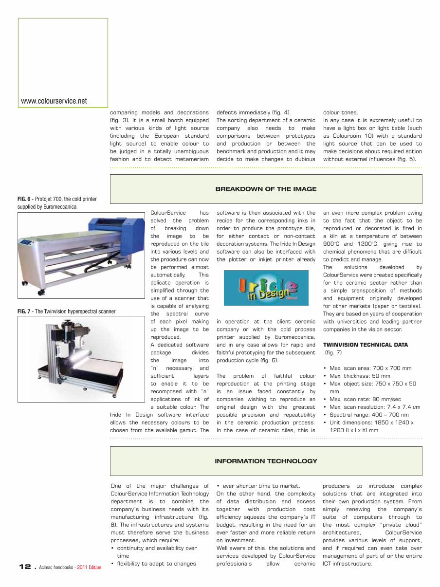
in operation at the client ceramic company or with the cold process printer supplied by Euromeccanica, and in any case allows for rapid and faithful prototyping for the subsequent production cycle (fi g. 6).
The problem of faithful colour reproduction at the printing stage is an issue faced constantly by companies wishing to reproduce an original design with the greatest possible precision and repeatability in the ceramic production process. In the case of ceramic tiles, this is
an even more complex problem owing to the fact that the object to be reproduced or decorated is fi red in a kiln at a temperature of between 900°C and 1200°C, giving rise to chemical phenomena that are diffi cult to predict and manage. The solutions developed by ColourService were created specifi cally for the ceramic sector rather than a simple transposition of methods and equipment originally developed for other markets (paper or textiles). They are based on years of cooperation with universities and leading partner companies in the vision sector.
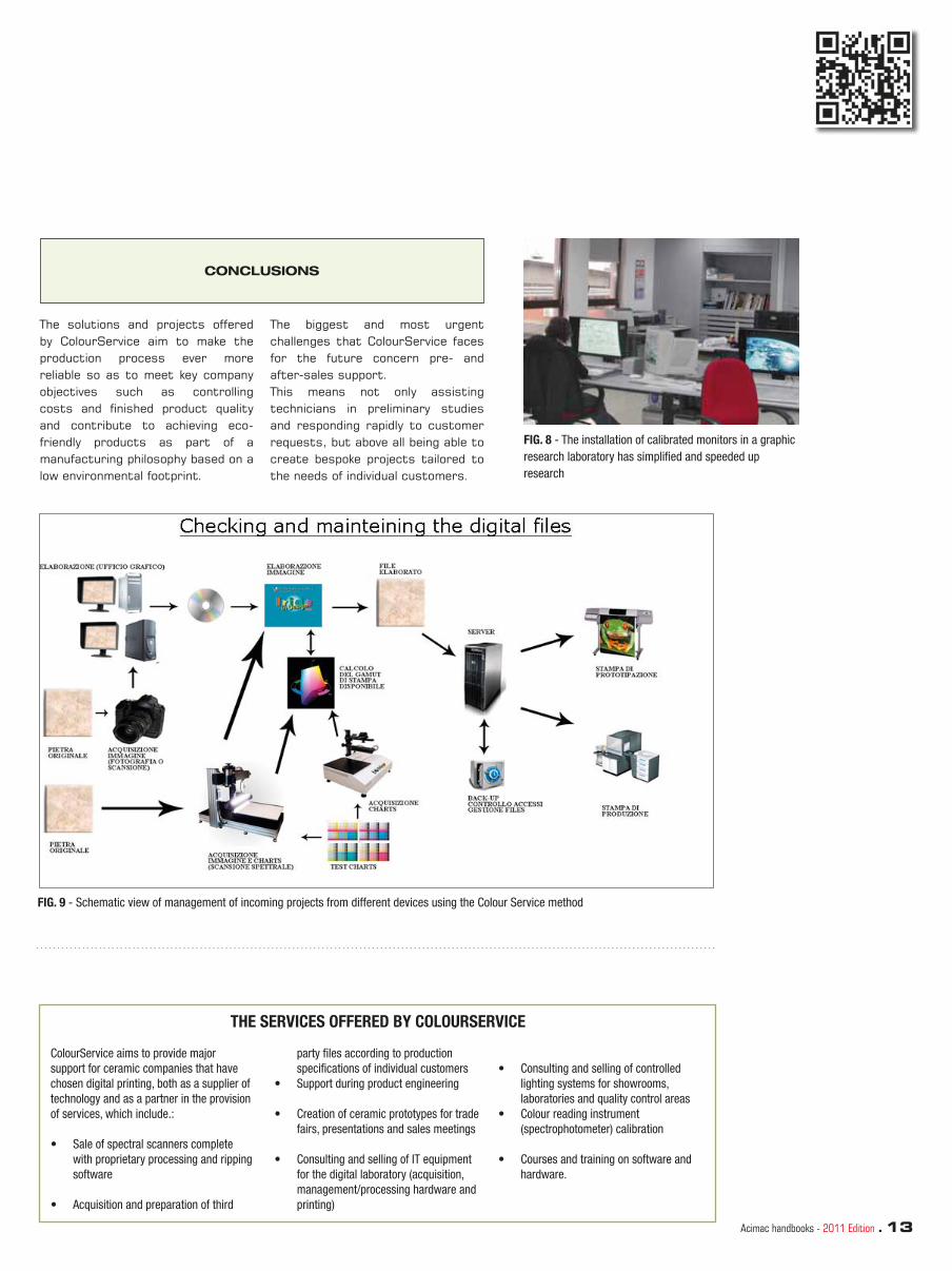
TWINVISION TECHNICAL DATA (fi g. 7)
• Max. scan area: 700 x 700 mm• Max. thickness: 50 mm• Max. object size: 750 x 750 x 50
mm• Max. scan rate: 80 mm/sec• Max. scan resolution: 7.4 x 7.4 µm• Spectral range: 400 – 700 nm• Unit dimensions: 1850 x 1240 x
1200 (l x l x h) mm
www.colourservice.net
comparing models and decorations (fi g. 3). It is a small booth equipped with various kinds of light source (including the European standard light source) to enable colour to be judged in a totally unambiguous fashion and to detect metamerism
defects immediately (fi g. 4). The sorting department of a ceramic company also needs to make comparisons between prototypes and production or between the benchmark and production and it may decide to make changes to dubious
colour tones. In any case it is extremely useful to have a light box or light table (such as Colouroom 10) with a standard light source that can be used to make decisions about required action without external infl uences (fi g. 5).
BREAKDOWN OF THE IMAGE
FIG. 6 - Protojet 700, the cold printer
supplied by Euromeccanica
FIG. 7 - The Twinvision hyperspectral scanner
INFORMATION TECHNOLOGY
Acimac handbooks - 2011 Edition . 13
FIG. 8 - The installation of calibrated monitors in a graphic
research laboratory has simplifi ed and speeded up
research
CONCLUSIONS
The solutions and projects offered by ColourService aim to make the production process ever more reliable so as to meet key company objectives such as controlling costs and fi nished product quality and contribute to achieving eco-friendly products as part of a manufacturing philosophy based on a low environmental footprint.
The biggest and most urgent challenges that ColourService faces for the future concern pre- and after-sales support. This means not only assisting technicians in preliminary studies and responding rapidly to customer requests, but above all being able to create bespoke projects tailored to the needs of individual customers.
THE SERVICES OFFERED BY COLOURSERVICE
ColourService aims to provide major
support for ceramic companies that have
chosen digital printing, both as a supplier of
technology and as a partner in the provision
of services, which include.:
• Sale of spectral scanners complete
with proprietary processing and ripping
software
• Acquisition and preparation of third
party fi les according to production
specifi cations of individual customers
• Support during product engineering
• Creation of ceramic prototypes for trade
fairs, presentations and sales meetings
• Consulting and selling of IT equipment
for the digital laboratory (acquisition,
management/processing hardware and
printing)
• Consulting and selling of controlled
lighting systems for showrooms,
laboratories and quality control areas
• Colour reading instrument
(spectrophotometer) calibration
• Courses and training on software and
hardware.
FIG. 9 - Schematic view of management of incoming projects from different devices using the Colour Service method
14 . Acimac handbooks - 2011 Edition
Visualisation, control, profi ling and colour management tools
systems, batching systems and software, as well as applications for formulating ceramic screen printing pastes.In recent years the company has entered the digital decoration segment, supplying ceramic producers with prototyping software that allows them to verify the graphic appearance
Euromeccanica has been specialising in decoration technologies for the ceramic sector since 1996. Prior to the advent of digital decoration, it operated in the fi eld of conventional decoration systems based on fl at screens and silicone rollers, offering grinding and paste preparation
of tiles without the plant costs involved in actually producing them.It has devoted a great deal of effort to the search for suitable solutions in the fi eld of colorimetry and ceramic colour management with the aim of identifying innovative solutions capable of improving and where possible simplifying existing systems.
by Marco Sichi
VISUALISATION AND CONTROL PERIPHERALS
Correct colour viewing has always been a crucially important aspect of colour management. Without accurate colour representation, users’ processing and printing efforts will be little more than an exercise in trial and error.Following an in-depth study of the sector, Euromeccanica established close cooperation and marketing links with the Japanese fi rm Eizo, a producer of monitors specially designed for colour graphics work (fi g. 1 and 2).But to view colours correctly, it is not suffi cient to have a good quality monitor – it must also be calibrated regularly to obtain a profi le that takes account of the monitor’s colorimetric characteristics and of the lighting conditions of the place where it is installed.For this purpose, Euromeccanica has long partnered with X-Rite, a leader in the fi eld of instrumentation for colour measuring and management. The partnership began with the production of sphere spectrophotometers for quality control and colour formulation and continued with calibration and viewing systems. Euromeccanica is an authorised distributor of these instruments and a certifi ed training and instrument calibration centre.
Besides viewing the image correctly on the monitor, it is also essential to view the fi nished piece correctly at the control stage. It is no longer satisfactory to use any kind of light or random light
source (such as daylight entering through a window) for comparing or choosing products or colours. It is essential to know exactly what type of lighting has been chosen and to be certain that it can be used over the entire operating cycle in different ambient, climatic or geographical conditions.Choosing the light source and using it as a reference for the entire ceramic production cycle (from the graphic design department to fi nished product sorting at the end of the cycle and through to the showroom) is essential for correct management of colour information (fi g. 3 and 4).Euromeccanica is the offi cial distributor for solutions that harmonise lighting conditions
at all stages of the ceramic production process: from desktop to laboratory and sorting system light booths through to the construction of harmony rooms for showrooms.
FIG. 1 - Monitor
FIG. 3
FIG. 4
FIG. 2 - Monitor

Acimac handbooks - 2011 Edition . 15
INSTRUMENTS FOR CHECKING PRINTING PROBLEMS
longer necessary to correct defects manually as instruments are available on the market for obtaining reliable data for defect correction. A typical example is the problem of banding that can occur on some
Inkjet technology is a relatively new development for the ceramic sector and the associated teething problems may give rise to printing defects. As in the case of the problems mentioned above, it is no
machines upon start-up or when changing heads, which can be entirely solved using a densimeter combined with a computer program that provides an immediate indication of the data that have to be corrected.
SOFTWARE AND HARDWARE SOLUTIONS FOR PROFILING
Profi ling is a crucial aspect of colour management. A precise knowledge of the printer’s gamut and the ability to change the colours of a project ensure that optimal performance can be achieved in given working conditions. This is particularly important when
conditions change to avoid having to make corrections by trial and error.The software/hardware solutions (measuring instruments and software) supplied by Euromeccanica can be used to create profi les for printing systems using either a
traditional method (starting out from RGB or CMYK colours) or with the new multicolour plug-ins, allowing profi ling to be performed with the actual colours that are present on the printer (fi g. 5 and 6).
FIG. 5
FIG. 6
A NEW COMPLETE SOLUTION
From an analysis of the needs of ceramic digital decoration, Euromeccanica has developed a new scanning and colour management system specifi cally designed for digital printers. This new solution is able to acquire high-resolution images and above all, thanks to the use of proprietary software, is able to perform fi le profi ling based on gamuts developed via internally produced testcharts.The solution has been developed principally for the ceramic industry and is able to:
• digitalise traditionally developed projects;
• create new designs with natural raw materials or other materials (prints, fabrics, etc.);
• profile files originating from different input peripherals;
• re-profile files as characteristics change.
This dedicated digital printing
solution allows users to fully exploit the peripheral’s print gamut and make a rapid comparison between all possible types of printing (different printers, different inks, glazes, fi ring cycles, etc.), adopting a scientifi c but very simple approach.The main advantages are:
• scientifi c method;• simplicity;• the possibility of determining
immediately the product percentage that can be reproduced with the target system, both visually and statistically;
• possibility of making an immediate comparison between two different systems;
• possibility of keeping the printing process under control.
The components
The system has three main components: the hyperspectral scanner, the scanning software and
the colour processing software.
The scanner
The hyperspectral scanner (fi g. 7) was developed in collaboration with the University of Parma, a leader in the fi eld of colour research. It was inspired by research aiming to obtain precise colour information in the fi eld of artwork restoration. The scanner is able to acquire graphic and spectral information (in the visible spectrum from 400 to 700 nm) over an area of 700x700 mm with three types of resolution: low (160 dpi), medium (320 dpi) and high (630 dpi). It consists of a transmission spectrophotometer coupled with a CCD capable of acquiring extremely high resolution images.The sample to be scanned is lit by halogen lamps that illuminate a spherical cylinder (D/0° lighting). This kind of lighting was chosen because it has always been used in colour reading instruments

16 . Acimac handbooks - 2011 Edition
www.euromeccanica.com
in the ceramic sector (SP62 sphere spectrophotometer) and is also the most effective for avoiding refl ections and light dispersion when scanning shiny or textured surfaces.
The acquisition software
The hyperspectral scanner is coupled with acquisition software that allows:• control of scanning parameters;• white and dark calibration;• choice of type of resolution;• data processing and saving;• joining of a number of scanned sections to
create large surface areas.
The colour processing software
The third component and the real heart of the system is the colour processing software, which performs all the following functions: • generating and printing the calibration
pages;• creating the target printer gamut;• importing spectral or graphic fi les;• visual and statistical checking of out-of-
gamut;• visual and statistical comparison
between two gamuts with the possibility of creating colour palettes for the two sets’ common or different colours;
• modifi cation of colours in acquired fi le; • printing of fi les according to required
specifi cations.
Operation of colour processing software
The process is divided into two stages that can be considered as two separate applications.The part concerning high-resolution scanning of objects is available as a single package, likewise the use of scanners and software for profi ling (a small dedicated scanner has been created for users interested in this specifi c function).
PHASE 1
Phase 1 includes acquiring data on the printing system, generating testcharts and then reading them after printing and fi ring to create a gamut containing the set of reproducible colours (fi g. 9 and 10).
PHASE 2
Phase 2 involves acquiring an original design or loading the image via a tiff lab fi le originating from different peripherals. The target printer is also chosen. It will be immediately possible to obtain a graphic representation of the two gamuts (printer and object) and a visual/statistical representation of the non-reproducible colours (fi g. 11 and 12).Colorimetric intent technology can now be used to alter the fi le in such a way as to reproduce the greatest possible quantity of
FIG. 7 - Hyperspectral scanner
FIG. 8 - Operation of the hyperspectral scanner
FIG. 9/10 - The colour processing software: phase 1 FIG. 11/12/13 -The colour processing software: phase 2

Acimac handbooks - 2011 Edition . 17
colour. The software automatically proposes the intent considered best for the selected type of object (fi g. 13 and 14). When the result is considered correct, it will be possible to send it
straight to the printer or save it in an exchange folder. The fi le is ready to be loaded on the machine; resolution, fi le format and layer separations are user-customisable options when setting up the printer.
NOTE
FIG. 14 - The colour processing software: phase 2
FIG. 15 -A graphic laboratory in ceramics

18 . Acimac handbooks - 2011 Edition
Digital decoration: product innovation
or process innovation? Renewing the business model
In this situation, the Italian ceramic industry – and especially companies operating in the Modena and Sassuolo area – must conduct a carefully analysis of the strategies behind the development of this innovative new decoration technology, which involves all players in the production chain, from ceramic producers to suppliers of plants, materials, software and
Digital printing is the latest, and in many ways a unique, technological innovation for the Italian ceramic tile industry and one that has become fi rmly established in the last two years. There are an estimated 120 digital printing machines now in operation in Italy, and this fi gure is expected to rise to more than 300 by the end of the current year.
design.To make such an analysis, it is necessary to have a clear picture of the current manufacturing scenario in Italy. In particular, this involves analysing the competitive forces involved in order to identify the strategies that producer companies must pursue to defend their competitiveness.
by Davide Corradini
The economic results for 2008 and 2009 have revealed a downward trend in production and sales volumes for the ceramic tile sector (fi g. 1).
This trend clearly indicates that the sector has entered a new phase of its life cycle distinguished by the following characteristics:
• Falling market demand• Increased competition from
products from other sectors (wood, glass, etc.)
• A search for maximum production effi ciency
• Production delocalisation towards countries with lower production
costs• Closure/conversion of production
facilities.
These are typical characteristics of a phase of decline or very advanced maturity.
To protect their competitiveness, companies must pursue a series of strategic objectives that differ according to the different stages in the chain of value. These can be subdivided according to Porter’s scheme of differentiation or cost leadership.The following table sums up these strategies:
TAB. 1 - COMPETITIVE STRATEGIES IN A MATURE MARKET
Stages in the chain of value Differentiation strategies Cost reduction strategies
Process inputs• Delocalisation
• Relationship with suppliers
Production• Quality differentiation
• Product innovation
• Economies of scale
• Outsourcing
• Economies of variety
• Process innovation
Distribution and sale • Customer service • Downstream integration
Transversal
• Communication
• Geographical diversification
• Market presence/Reputation
• Human resource management
FIG. 1 - Tile production in Italy from 1994 to 2009. Source: Confi ndustria Ceramica 2010
THE STATE OF THE ITALIAN CERAMIC TILE INDUSTRY
cost reduction. In this respect, inkjet printing brings a number of advantages, ranging from the possibility of reducing the number of colour tones in production to simpler management of screen printing materials and shorter product
What role can digital printing play to support companies in their pursuit of these goals?Concentrating on the aspect of production, we can affi rm that digital technology is a process innovation that serves to pursue goals of
development times.Another important strategic goal that digital printing can help to achieve is the development of producer/supplier synergies, again with a view to process cost cutting. Inkjet printing requires a high degree

Acimac handbooks - 2011 Edition . 19
of standardisation of the production process and of the materials used, or at least this is the trend that has accompanied the introduction of this new decoration technology. This makes it necessary to strengthen interactions between ceramic producers and suppliers of materials, machinery and graphic design services to ensure that the various components are harmonised and together contribute to an overall
reduction in production costs.But alongside cost cutting we also fi nd strategies aimed at product differentiation. In this respect, inkjet printing is an exceptional tool for developing innovative aesthetic proposals. Suffi ce it to think of the high degree of graphic variability that can be achieved for each individual product, including the potential of non-contact printing, at the same time combining
colour, graphic design and texture in combinations that until recently would have been unimaginable.
The goals that can be pursued through the introduction of digital printing can be summed up as:
• Effi ciency• Innovation• Competitiveness.
SWOT ANALYSIS OF DIGITAL TECHNOLOGY
Using the SWOT diagram (Strengths, Weaknesses, Opportunities, Threats) to analyse the new technology, we can determine the key strengths and opportunities that it offers and
also discover the weaknesses and threats that must be carefully avoided if we wish to prevent the enormous potential of inkjet technology from merely accelerating the process of decline of the Italian
ceramic district.The following is a summary of the analysis, which for brevity lists just a few of the factors contained in the SWOT matrix.
TAB. 2 - SWOT ANALYSIS OF DIGITAL TECHNOLOGY IN THE CERAMIC INDUSTRY
Strength Weaknesses
• New decorative potential
• Reduction in industrialisation times
• Reduction in storage costs of decoration materials
• Limited colour potential
• Absence of a textural or material content
• Introduction of new operating problems
Opportunities Threats
• Product innovation
• Customisation of production batches
• Improved quality/price ratio
• Standardisation of fi nished product
• Risk of ink-jet driven rather than ink-jet added design
• Switching from a ceramic design to a graphic design
The left hand side of the diagram has already been much discussed, so it will be more interesting to concentrate on the right hand side, starting out with the weaknesses.
The fi rst weakness is the limited colour potential. Although digital printing coupled with an adequate digital colour management system is able to create a wide range of colours from a limited number of inks, the colour gamut is far from infi nite. Moreover, the gamut is limited by a series of parameters determined not only by the colours of the inks but also by the background and covering glazes, the fi ring cycles, the colour of the substrate, the printing machine and the colour profi ling and management system adopted.
This means that to achieve the maximum gamut it is necessary to assure a high degree of standardisation of all these variables at the expense of process fl exibility. Conversely, the search for greater fl exibility gives rise to operational and management complications. An example of this is the development of custom ink colours to meet each customer demands, which increases the number of warehouse articles and the number of colour profi les that need to be managed.
A second weakness is the absence of material or textural content. Unlike screen printing, digital printing technology is unable to deposit a substantial quantity of material on the tile, so its contribution is limited to colour and graphic design. So digital printing by itself lacks
one of the essential components of ceramic tiles, which are not only visually attractive but also have a strong tactile appeal.
Last but not least, digital printing introduces new operating problems in that new tools and areas of expertise have to be acquired, such as those relating to digital colour management. And although digital printing does allow for greater colour uniformity during production, the fi nished product as we mentioned is infl uenced by a large number of process variables. As for threats, there are a number of important points that need to be stressed.Firstly, it’s a very short step from process standardisation to

20 . Acimac handbooks - 2011 Edition
threat rather than an opportunity because it would increase the competitiveness of emerging countries with low production costs which would be able to replicate Italian products with relative ease.
Another threat that arises as the natural consequence of the excessive efforts to adapt the ceramic process to digital printing is that of a transition from ink-jet added to ink-jet driven product design. In other words, there is a risk of imposing the use of digital printing
product standardisation. In order to stabilise process variables and achieve cost benefi ts, companies seek to rationalise the materials they use for decoration and harmonise their fi ring cycles. But this has the result of creating products with a low technological complexity that can easily be reverse engineered. In short, there is a risk that products will only be differentiated aesthetically by their graphic content, which is essentially the result of the digital management of printed images. In this scenario, product innovation or diversifi cation would clearly be a
on all company activities, from design to sales. The production process must exploit the opportunities offered by inkjet printing rather than being constrained by it; aesthetic product design must be seen as a new tool, not the only tool available. Likewise from a commercial perspective, it is worth bearing in mind that a tile produced with digital printing is not a new product: it is still a tile. The innovation concerns the process, while the only innovation that affects the product is that of aesthetics.
EMERGING NEEDS
www.colorobbia.com
to create new colour and surface solutions while making every effort to integrate digital printing effectively with conventional decoration techniques.As for effi ciency, companies need to use digital printing to create products that are already in their catalogues in an attempt to cut production costs, but they also need to rapidly solve the new management problems created by digital printing. As regards competitiveness, a key factor for competing at a global level through skilful use of inkjet printing is that of cutting product development times so as to keep
Clearly, the strengths, weaknesses, opportunities and threats listed above give rise to certain needs on the part of ceramic tile producer companies. In other words, companies need to exploit the strengths and opportunities of the new technology while avoiding the weaknesses and threats. It is worth analysing these needs in the light of the three key aspects of competitive strategies: innovation, effi ciency and competitiveness.Given that digital printing is a process innovation, in order to innovate the aesthetic content of their products companies need
ahead of the competition and rapidly launch new series onto the market. Of course these new aesthetic offerings must be complex and diffi cult to imitate.
To sum up, companies require a set of products/services that deliver:
• Quality, to support innovation• Reliability, to exploit the cost
effi ciency benefi ts offered by inkjet printing
• Expertise, in other words the design capability necessary to secure a competitive advantage from digital technology.
THE PROPOSALS OF GLAZE AND COLOUR COMPANIES
complex production process and huge research and development costs, given that an ink is far more than a mere mixture of a traditional fi nely ground pigment and a few organic additives. Inks are now widely recognised as highly delicate and complex physical systems that take several months to develop, after which they must be tested
A glaze and colour producer aiming to become a key partner for ceramic companies in addressing the challenge of digital printing must offer products and services that stand out in terms of quality, reliability and expertise.The quality of products is refl ected in the development of new organic/inorganic systems through a
in cooperation with the machinery manufacturers. They must be optimised in terms of numerous quantitative and qualitative criteria including chemical and physical parameters, colour balance, gamut and durability, not to mention eco-compatibility.Conversely, to assure a high service quality, the glaze and colour company

Acimac handbooks - 2011 Edition . 21
have a low risk of malfunctions. A reliable service includes providing technical support tailored to the new areas of expertise required by digital technology.The expertise or design capacity of a glaze and colour company is refl ected in its ability to offer inks that integrate perfectly with traditional ceramic materials and allow for wide versatility of use in creating various types of surface.
must acquire new expertise in the fi eld of colour management. However, this is a lengthy process because colorimetry is a complex science and also because digital colour management systems for ceramics are currently undergoing continuous development.To achieve reliability, the inks must be perfectly compatible, both chemically and physically, with the printing equipment and therefore
This expertise is based on continuous internal research into the combination of inks with glazes, grits, screen printing pastes and so on. Last but not least, glaze and colour producers must be able to integrate new digital expertise with existing ceramic technologies to support customers in all stages from product design through to industrialisation.
CINKS: THE RANGE OF OFFERINGS FROM COLOROBBIA
improvement, the research and development efforts for these inks are based on 4 main factors:
• search for the widest gamut• the maximum fl exibility of use of
inks, which need to be suitable for all types of products
• stability for a period of 6 months from the time of manufacture, guaranteed by perfect equilibrium of the organic/inorganic mixture
• environmental safety: care for human health and the environment is crucially important for Colorobbia. CINKS are not subject to risk labels and do not require ADR/IMDG/ICAO
Colorobbia’s current range of offerings for digital printing consist of a set of products and services identifi ed by the trademark CINKS.
The CINKS range consists of 8 products:
• Al-Co cyan (for fl oor tiles) • Si-Co cyan (for wall tiles)• Red-Brown• Brown• Beige• Yellow• Black• Pink
With a view to ensuring continuous
labelling for transport.
The service offered by Colorobbia forms part of a customer relationship management system.On the basis of the customer’s requests, the orders management system coordinates various working groups internally in order to provide all-round support. This includes establishing close cooperation in the design and development of fi nished products and supporting customers in product industrialisation. For this purpose, Colorobbia has a digital printing technical support team that works worldwide in
FIG. 2 - Structure of the CINKS service, built around customers’ needs
Graphic design
Project development
Design
R&D in inks
and traditional materials
Inkjet support team
Industrialisation
Customer
22 . Acimac handbooks - 2011 Edition
close partnership with research and development personnel to deliver solutions tailored to customers’ specifi c needs.
In terms of human and material resources, the design support structure consists of a worldwide network of laboratories that employ graphic designers and ceramic technicians with expertise in digital
colour management. It has a team of 12 ceramic technicians focusing on developing new fi nished product proposals and 12 plotters, along with hardware and software tools for rapid prototyping of fi nished products.To provide support during the product industrialisation stage, the company has set up a task force of 20 ceramic technicians to provide after-sales support in the digital sector.
This support is available worldwide thanks to Colorobbia’s 14 global branches.These fi gures give an idea of the growing investments made by Colorobbia with a view to becoming a key partner for its customers the world over in their process of adopting digital printing.
www.colorobbia.com
FIG. 3 - The resources invested by Colorobbia in the CINKS service
CONCLUSIONS
Following this analysis of the current competitive scenario and the role of digital printing, we can draw some important conclusions.After being badly hit by the crisis of 2009 and under pressure from fi erce international competition, the Italian ceramic tile producers are striving to gain a competitive advantage by cutting industrial costs and focusing on aesthetic product innovation.Inkjet technology is a process innovation that can help achieve these goals.But alongside its opportunities and
strengths, inkjet technology also hides a number of weaknesses and threats. It is therefore essential to adopt a systemic approach to the introduction of this technology to avoid accentuating the potential risks. A systemic approach involves strengthening the relationship between producer and suppliers, who must collaborate through joint design of the fi nished product while striving to achieve the maximum production effi ciency and to create products that cannot be imitated as a result of the unique Italian capacity
for innovation.In such a scenario, the characteristics that a set of products/services offered by a glaze and colour producer must have are quality, reliability and expertise.Through its CINKS brand name, Colorobbia offers products and services with a high standard of quality and reliability backed by expertise and longstanding experience in the ceramic sector and aims to serve as a key partner in helping its customers meet the challenge posed by the introduction of digital technology.
Network of 9 laboratories worldwide:
ceramic graphic design technicians
specialising in digital colour
management.
Team of 12 ceramic technicians
focusing on continued aesthetic
research.
12 plotters for digital printing along
with relevant hardware and software.
Design Industrialisation
Customer
Team of 20 technicians providing
after-sales support in digital printing.
Global service guaranteed by 14
branches worldwide.

Acimac handbooks - 2011 Edition . 23
NOTE

24 . Acimac hanbooks - 2011 Edition
Pigmented ceramic inks• Reduction in model design times
and costs• Reduction in warehouse stock of
consumables and decorative products in general
• Printing on textured surfaces and on tile edges
• Elimination of breakages and aesthetic defects deriving from contact decoration
• The high degree of randomness of the high-defi nition graphic design (Figure 1).
All these advantages make inkjet technology a genuine innovation.
Whether we like it or not, digital decoration is now part of the ceramic industry so this technology must be understood and exploited to the full. The benefi ts it brings are undisputed and far outweigh any doubts that remain concerning product logistic management and limited colour gamut.
The introduction of digital decoration has brought the following advantages:
• The option of performing small runs or even producing single pieces
It was therefore a perfectly natural decision for INCO Industria Colori to include a new series of high-performance pigmented inks in its product range.This was made possible by the company’s deep knowledge of the fi eld, along with carefully selected investments in research, close cooperation with plant manufacturers and a strong focus on customers’ needs.However, these efforts would be pointless if the experience accumulated over the years were not shared with customers
authentic process of chemical synthesis that adopts various techniques (coprecipitation, sol-gel process, microwave hydrothermal process, etc.) to form nanoparticles from the smallest units upwards – atom by atom, molecule by molecule and so on. The top-down process instead produces nanoparticles by reducing the dimensions of larger sized particles by various techniques, one of which is high-energy grinding with microsphere mills.This is the technology most commonly adopted for the production of ceramic inks because the bottom-up process is excessively expensive for the ceramic sector and is mainly used for synthesising nanoparticles for coatings and electronics (Figure 3).
INK COMPOSITION
by Daniele Verucchi, Maurizio Cavedoni
Fig. 1
Fig. 2 - Composition of pigmented
ceramic inks
Flat silk-print: 127 DPI and just one face
Roto-print: 127/254 DPI and maximum three faces
Inkjet-print: 360 DPI several faces
A pigmented ceramic ink consists of a solid phase (20-45%) and a non-aqueous liquid phase mixed together perfectly homogeneously.The solid phase consists mainly of
specially designed inorganic pigments (zircons, spinels, etc.) and serves to give the ink the requisite colour.The liquid phase consists of polar and nonpolar substances, stabilisers and dispersants and provides the ink with long-term stability against fl occulation and sedimentation. It also determines certain chemical and physical properties (viscosity, surface tension and conductivity) that infl uence the formation of the drop during printing, given that drop size, speed and stability at any given frequency depend on these properties (Figure 2). There are two approaches to the synthesis of nanoparticles, the bottom-up process and the top-down process.The bottom-up process is an

Acimac hanbooks - 2011 Edition . 25
Fig. 3 - Top-down and bottom-up
processes
THE TOP-DOWN PROCESS
Let’s take a detailed look at the top-down process of high-energy milling.In this process, the homogeneous mixture of liquid phase and pigment is recirculated through a grinding chamber fi lled 80-90% with yttrium-stabilised zirconium oxide microspheres of diameter 0.20 mm. Inside the grinding chamber, a dedicated rotor imparts an extremely high peripheral velocity to the microspheres, thereby introducing energy to the milling process. The continuous passage of ink through the grinding chamber produces the desired submicronic particle size distribution (Figure 4).
This process forms crystals of very small size (0.2 µm) compared to the dimensions of the pigment particles at the beginning of the process (3-5 µm) (Figure 5). Only oxides that are specially developed to withstand such an intense milling process are able
to maintain a high colour yield and withstand the chemical action of glazes and the fi ring cycle.
The inks prepared by means of this process of synthesis are susceptible to phenomena of instability deriving from the submicronic solid-solvent dispersions. This instability is often caused by a combination of two physical processes:
1. An increase in particle size (aggregates) due to fl occulation;
2. The movement of particles inside samples, resulting in creaming or sedimentation.
This instability may have a major impact on the quality of the fi nished product, giving rise to undesirable concentration gradients and therefore poor colour rendering and irreversible clogging of the print nozzles.
Keeping the pigmented part of an ink in suspension in various conditions of storage and use is therefore the challenge that ceramic ink formulators face constantly. For this purpose, various additives are used to promote “wettability” of the pigment and to prevent phenomena of agglomeration and sedimentation (Figure 6).
The instability that may be present in an ink can be monitored using an instrument called Turbiscan, which detects the phenomenon in just a few hours or days when a visual analysis may take weeks. This instrument (used at INCO research and development laboratories) allows the formulations to be optimised, the best additive chosen for maximum ink stability, and precise quality control to be performed on the various production runs.
Fig. 4 - Production layout of
pigmented ceramic inks
Fig. 5 - Comparison between particle size distributions of a
traditional pigment for glaze colouring (Jet mill) and of an ink (High
Speed)
Fig. 6 - Instability of solid/solvent dispersions
MEASURING PRINCIPLE
The central unit of the instrument consists of a detection head that moves vertically through a cylindrical glass cell with a fl at bottom section where the ink is contained.
The head contains a pulsed near-infrared light source (�=850 nm) and two synchronous detectors. The transmission detector receives the light that passes through the
specimen, while the backscattering detector receives light scattered back from the specimen. The head analyses the specimen over its entire length (around 65

26 . Acimac hanbooks - 2011 Edition
www.incolours.it
mm), acquiring transmission and backscattering data every 40µm (which means 1,625 transmission and backscattering transmissions per scan) (fi gure 7 and 8). This instrument performs scans at various programmed times and superimposes all the profi les on a graph in order to detect instability. In a graph of a stable product, all the scans made over time lie more or less on a single curve (Figure 9), whereas an unstable specimen displays variations in the acquired profi les (Figure 10). On these graphs, the transmission and backscattering values are shown on the ordinate and the height of the cell containing the specimen on the abscissa. The following fi gures show an example of Turbiscan analysis of two ink specimens with a high degree of instability. Figure 11 shows that the backscattering levels increase in the zone corresponding to the bottom of the cell containing the specimen (zone
on the left hand side of the graph) due to a concentration of particles in this zone of the cell (sedimentation). This concentration can be detected from the scans within the fi rst few hours of monitoring even though no variations are evident to a visual inspection. Observing the right hand side of the graph (which corresponds to the upper zone of the cell), a reduction in backscattering can be noted due to a phenomenon of clarifi cation of the specimen in this zone. Figure 12 shows the classic behaviour of a specimen in which the particles have a tendency to fl occulate. The backscattering values can be seen to decrease progressively over time along the entire cell due to phenomena of particle aggregation, which make the specimen gradually more transparent to the light source.While sedimentation is reversible, fl occulation is not and must be strictly avoided so as not to cause clogging of the print heads and consequently undesirable line defects on the printed tiles.
Fig. 7 - Turbiscan: backscattering
Fig. 8 - Turbiscan: transmission
Fig. 9 Fig. 10
Fig. 11 - Sedimentation and clarifi cation
phenomena
Fig. 12 - Flocculation phenomena
STABILISATION OF PARTICLES AGAINST FLOCCULATION
Due to the large specifi c surface area created and the charges that are formed on the surface of
individual particles, during milling these particles have the tendency to reaggregate and form agglomerates
(a process referred to as fl occulation). For this reason, in the top-down ink preparation process it is very

Acimac hanbooks - 2011 Edition . 27
important to stabilise the particles so as to avoid the occurrence of fl occulation phenomena over time. The particles can be stabilised against fl occulation by two different methods, electrostatic and steric stabilisation.The fi rst involves covering the particles with charges of the same sign which therefore repel each other. This is a complicated method because is it strongly dependent on pH and on the concentration of electrolytes that are placed in solution.The second method involves covering the particles with polymeric chains of appropriate length. The chains have an end section
with an affi nity with the particles of pigment which therefore bonds with them, and a terminal chain that acts as a physical separator/spacer between the particles. This is the method that is most widely used for the preparation of pigmented ceramic inks (Figure 13).
Obtaining products that are less susceptible to sedimentation and fl occulation is a very important qualitative goal for ink producers as these factors infl uence the shelf life of inks and their behaviour in printing machines, where the ink is maintained constantly at temperatures of between 40°C and 50°C (a highly stressful situation that accelerates the instability phenomena).
Fig. 13 - Steric (left) and electrostatic stabilisation
CHEMICAL AND PHYSICAL PROPERTIES OF PIGMENTED CERAMIC INKS
Inkjet decoration in the ceramic sector uses printheads based prevalently on “drop on demand” (DOD) technology for ink deposition. This technology allows precise quantities of a functional ink to be deposited in the form of drops via application of a very short pressure pulse.The operating principle of drop jetting is to generate pressure waves in a tube fi lled with ink behind an orifi ce. At the end of the orifi ce, the meniscus of the liquid is maintained by surface tension.A piezoelectric system generates a pressure wave, which propagates against the fl uid’s surface tension forming a small droplet which is ejected from the nozzle. In suitable electrical conditions and with appropriate chemical and physical properties of the ink, the ejected liquid forms a single droplet.Inks with inappropriate rheological parameters will result in fi ring instability and drops with a very elongated tail. The length and lifetime of the drop tail infl uence the positioning precision and therefore resolution
of the printing process. Inks are characterised by numerous chemical and physical properties, some of which (speed, size, consistency of the drop) signifi cantly affect their ability to be fi red through printheads using drop-on-demand technology.The fi rst parameter that defi nes a pigmented ceramic ink is its particle size distribution. The average size of particles of ceramic pigmented inks is normally around 200-220 nm and 100% of the particles are smaller than 700-800 nm.Viscosity, surface tension and density are all factors that to some degree infl uence droplet formation.The pressure sound wave generated by the deformation of the piezoelectric element, which causes the droplet to be ejected from the printhead nozzle, is strongly dependent on viscosity. Using inks with as close to Newtonian behaviour as possible and with viscosity values of between 8-14cP (at the deposition temperature) ensures optimal droplet formation without the occurrence of undesirable satellite
droplets (much smaller droplets located around the main droplet) which give rise to defects during printing.Surface tension also has a direct infl uence on droplet formation. High values of surface tension require a higher voltage to achieve a constant droplet speed, whereas low values may lead to breakage of the meniscus inside the nozzle. This may result in air entrapment, causing discontinuities in the ink fl ow and the consequent occurrence of line defects during printing. Values of between 22-35 mN/m allow for good ink management during production.Density (values between 1-1.5 g/cm3) does not directly infl uence droplet formation but does determine the speed of propagation of
Fig. 14/15 - Correct jettability (above)
and uncorrect jettability (below)
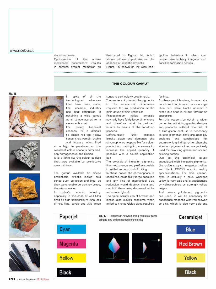
28 . Acimac hanbooks - 2011 Edition
the sound wave.Optimisation of the above-mentioned parameters results in correct droplet formation as
illustrated in Figure 14, which shows uniform droplet size and the absence of satellite droplets. Figure 15 shows an ink with non-
optimal behaviour in which the droplet size is fairly irregular and satellite formation occurs.
www.incolours.it
THE COLOUR GAMUT
In spite of all the technological advances that have been made, the ceramic industry still has diffi culties in obtaining a wide gamut at all temperatures for a reasonable cost. For purely technical reasons, it is diffi cult to obtain red and yellow tones that remain stable and intense when fi red
at a high temperature, so the resultant colour space is deformed, non-homogeneous and limited. It is a little like the colour palette that was available to prehistoric cave painters.
The gamut available to these prehistoric artists lacked cold tones such as green and blue, so they were unable to portray trees, the sky or water. In today’s ceramic industry, especially in the case of wall tiles fi red at high temperature, the lack of red, lilac, purple and vivid green
tones is particularly problematic. The process of grinding the pigments to the submicronic dimensions required for ink production is the main cause of this limitation.Praseodymium yellow crystals normally have fairly large dimensions and therefore must be reduced in size by means of the top-down process. Unfortunately this process breaks down and damages the chromophores responsible for colour production, making it necessary to increase the applied quantity, if possible with a double application bar.The crystals of inclusion pigments (iron red, orange and pink) are unable to withstand any kind of milling. In these cases the chromophore is contained inside fairly large capsules and any kind of mechanical size reduction would destroy them and result in them being dispersed in the substrate (glaze).The spinel structures of browns and blacks also exhibit problems when milled to the particles sizes required
for inks. At these particle sizes, browns take on a tone that is much more orange than red, while blacks assume a green hue that is all too familiar to operators.For this reason, to obtain a wider gamut for obtaining graphic designs and products without the risk of a blue-green cast, it is necessary to use pigments that are specially designed and synthesised for submicronic grinding rather than the standard pigments that are routinely used for colouring glazes and screen printing pastes.Due to the technical issues associated with inorganic pigments, the colours cyan, magenta, yellow and black (CMYK) are in reality approximations. For this reason, cyan is actually a blue, whereas yellow is very pale and is substituted by yellow-ochres or strongly yellow beiges. And unless gold-based pigments are used, it will be necessary to substitute magenta with red browns or pink, which is also very pale and
Fig. 17 - Comparison between colour gamuts of paper
printing inks and pigmented ceramic inks.
Fig. 16
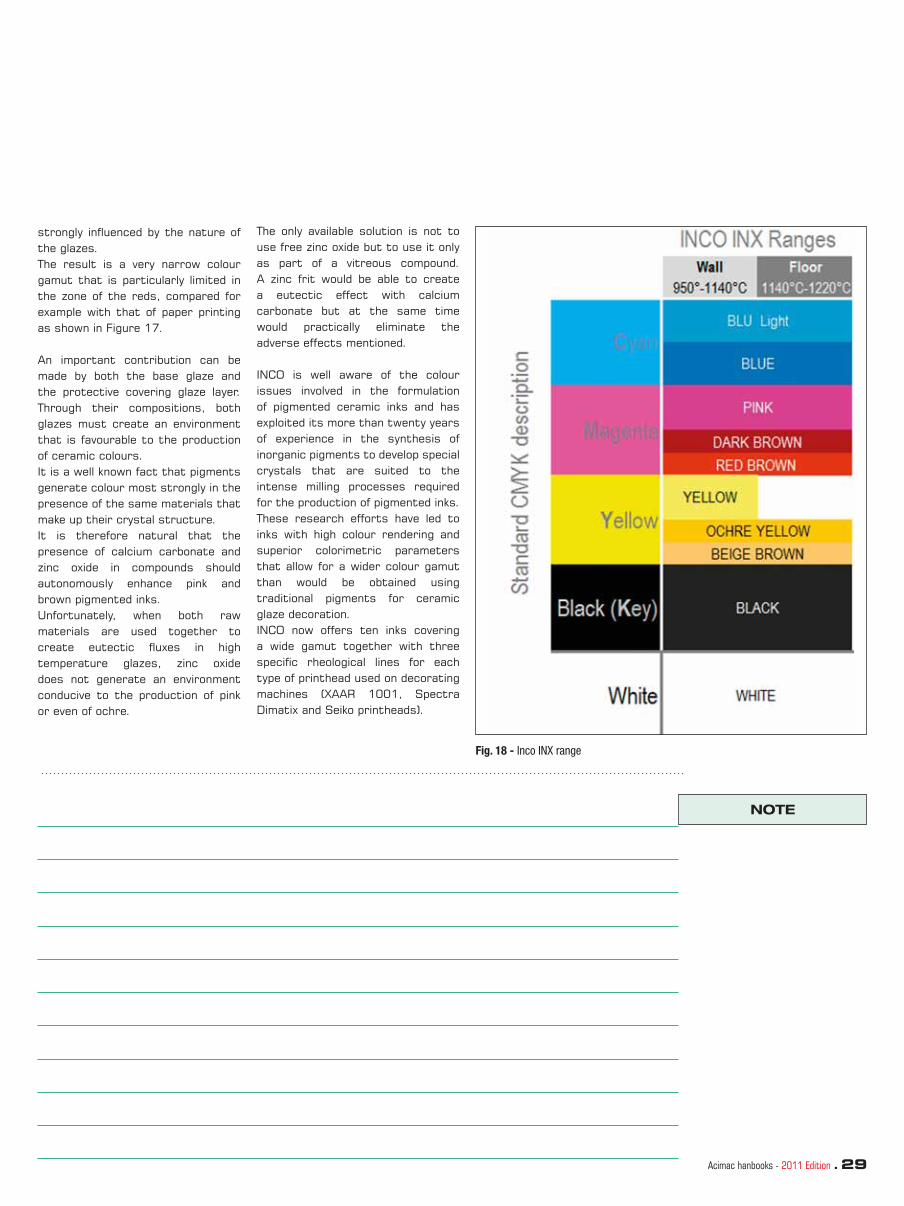
Acimac hanbooks - 2011 Edition . 29
Fig. 18 - Inco INX range
NOTE
strongly infl uenced by the nature of the glazes.The result is a very narrow colour gamut that is particularly limited in the zone of the reds, compared for example with that of paper printing as shown in Figure 17.
An important contribution can be made by both the base glaze and the protective covering glaze layer. Through their compositions, both glazes must create an environment that is favourable to the production of ceramic colours. It is a well known fact that pigments generate colour most strongly in the presence of the same materials that make up their crystal structure.It is therefore natural that the presence of calcium carbonate and zinc oxide in compounds should autonomously enhance pink and brown pigmented inks. Unfortunately, when both raw materials are used together to create eutectic fl uxes in high temperature glazes, zinc oxide does not generate an environment conducive to the production of pink or even of ochre.
The only available solution is not to use free zinc oxide but to use it only as part of a vitreous compound. A zinc frit would be able to create a eutectic effect with calcium carbonate but at the same time would practically eliminate the adverse effects mentioned.
INCO is well aware of the colour issues involved in the formulation of pigmented ceramic inks and has exploited its more than twenty years of experience in the synthesis of inorganic pigments to develop special crystals that are suited to the intense milling processes required for the production of pigmented inks.These research efforts have led to inks with high colour rendering and superior colorimetric parameters that allow for a wider colour gamut than would be obtained using traditional pigments for ceramic glaze decoration.INCO now offers ten inks covering a wide gamut together with three specifi c rheological lines for each type of printhead used on decorating machines (XAAR 1001, Spectra Dimatix and Seiko printheads).

30 . Acimac hanbooks - 2011 Edition
Digital glazes for an entirely digital glazing and
decoration processcustom batches tailored to the needs of the market.
Inkjet technology was fi rst developed in the 1970s as a means of printing brand names and product codes. Over the years the technology evolved and expanded into other sectors, especially graphic arts. In 2000 the fi rst prototype of an industrial machine was introduced into the ceramic sector. Enormous progress has been made over the last decade. The constant development of printheads, electronics, software and inks has allowed inkjet technology to become established in the ceramic sector.
The last ten years can be divided into two basic periods. In the fi rst period, which lasted until around 2006, the inkjet system used solely soluble inks.
The introduction of digital inkjet technology constitutes one of the most important advances in the ceramic tile industry’s recent history. Following the advent of single-layer roller kilns and the important development of rotary decoration systems with engraved silicone rollers, this latest advance represents an extraordinary innovation for the ceramic sector. Inkjet decoration is a historic development and one of the few technological innovations capable of helping ceramic fl oor and wall tile manufacturers improve their market position through differentiated products. It allows for greater fl exibility and productivity of manufacturing facilities without increasing operating costs and at the same time makes for better warehouse management, meeting the need for production of small
Very few machines were installed in this period given the severe limitations of the system, particularly concerning chromaticity, which was penalised by the soluble inks with their instability defects and high costs. But the second period saw a big leap forward, particularly with the introduction of pigmented inks. With these sets of inks, inkjet printers were already capable of printing a large portion of the colour space normally adopted in the ceramic industry and, importantly, with very competitive costs. The progress was further accelerated by the arrival of new players in the competitive arena: new machinery producers and new glaze and colour producers, all with the shared goal of offering the ceramic industry increasingly optimised solutions.
Esmalglass-Itaca Grupo
CURRENT ADVANTAGES AND DISADVANTAGES OF INKJET TECHNOLOGY
The advantages of this technology – such as high-defi nition and non-contact decoration, the possibility of adapting to any size and surface texture and decorating 100% of the surface, as well as the high graphic versatility deriving from the larger dimensions of the designs – led to highly signifi cant aesthetic improvements and enabled product lines to be developed for the high end of the market. However, this technology not only creates products with a competitive edge but also offers numerous advantages in terms of internal processes. A typical example is the reduction in the cost of new product development through a decrease in the number of tests, time invested and also the costs of consumables typical of conventional decoration. Technology also allows for greater fl exibility and speed in changing the
model, and likewise a considerable reduction in the number of colour tones produced, while considerably speeding up the entire production process. According to surveys conducted amongst users of this technology, all these advantages are obtained without increasing operating costs per square metre, and in many cases they are considerably reduced. The simplifi cation and reduction in inventory due to the possibility of producing virtually on-demand and the smaller number of colours allow for a considerable improvement in the company’s working capital. In short, it is one of the very few technologies capable of meeting the needs of the entire company and its management, from the production manager to the head of new product development, the sales director, the fi nancial director and the general manager!
However, digital technology displays a number of weaknesses or disadvantages, such as the limited colour gamut of inks compared to conventional decoration systems, the still limited robustness of these systems to withstand ceramic manufacturing environments, and the fact that it is not possible to increase the productivity of machines without sacrifi cing defi nition or making substantial investments to double up the printing bars. Colour rendering and ink consumption depend on the chemical composition of the glaze and the fi ring cycle, so the composition of the glazes must be optimised and the production variations must be minimised and controlled so as not to have to continually retouch graphic archives. Furthermore, until know the inks developed for this technology have been pigmented inks which had the

Acimac hanbooks - 2011 Edition . 31
of the tile solely in terms of colour, which is obviously essential for
purpose of contributing digitally to the graphic design and aesthetics
product development.
THE AIM OF THE ESMALGLASS-ITACA RESEARCH PROJECT
completely digital glazing line? This is the goal of the research project described in this presentation, which aims to develop glazes for application with digital systems that are capable of decorating and glazing simultaneously and in a synchronised fashion so as to apply material effects while enjoying all
But ceramic is not just colour or graphic design, it is also a play of materials, contrasts, tactile and visual sensations, luminosity and texture, and it is this that sets it apart from other surface covering materials. So why not exploit the enormous advantages of digital technology in applying materials and create a
the advantages of digital systems. But the real innovation concerns the process given that for the fi rst time it will be possible to produce a tile using entirely digital technology, extending to other ceramic materials the many advantages that digitalisation already offers in terms of colour and graphic design.
FIG. 1 - Particle size distribution of a DPG glaze
RESULTS OF THE RESEARCH PROJECT: DPG DIGITAL GLAZES
After years of study conducted by experts in injection technology and nanometric glazes, Esmalglass-Itaca is presenting the new family of Digital Printing Glazes (DPG). With this revolutionary digital solution it is possible for the fi rst time to decorate a tile entirely with digital technology, from the initial engobe through to decoration and the fi nal tile protection layer.
This DPG family of digital glazes was designed and developed specifi cally for digital application using DOD (Drop On Demand) injection heads and offers new potential for the digital ceramic process.
The family consists today of clear digital glazes (polished or matt), matt white digital glazes and polished digital glazes which are suitable for all existing manufacturing technologies.
• Clear DPG Digital Printing Glaze (polished or matt).
Designed for use as the fi nal protection layer on the tile and to create for the fi rst time entirely digitally a covering design that is perfectly synchronised with the base design.
• Matt White DPG Digital Printing Glaze.
Designed for two separate uses, either as a white ink for creating decorations (e.g. veins on a dark background) or as a base for the tile or for enhancing the colour of digital inks.
• Polished DGP Digital Printing Glaze.
Designed to create new decorative lights and brilliance effects.
The DPG Digital Printing Glazes contain nanometric particles with
a strictly controlled particle size distribution that deliver excellent physical stability as well as assuring excellent injection printhead performance, a critical factor in this research project. Proceeding from a micronic to a nanometric scale, a detailed investigation was conducted of the changes in the properties of the materials of both a vitreous and crystalline nature so as to design and optimise innovative compositions with good technical and aesthetic properties required for decorated ceramic products.
FIG. 2/3 - Examples of tiles produced
using White Matt DPG Digital Printing
Glaze

32 . Acimac hanbooks - 2011 Edition
Aesthetic advantages• Non-contact digital application
for glazing low-reliefs• Glazing right up to the edge of
the tile without build-up • Versatility in the glazing design • Glazing with high print quality• Ability to reproduce other
techniques (double fi lling, double pressing, etc.)
• Little repetitiveness when glazing large sizes
• Rapid model development.
This allows for:• A high degree of differentiation • Good reproducibility• New creative scope for designers• The ability to synchronise the
glazing with reliefs and designs
Production advantages• Elimination of bottlenecks in
glaze preparation• Guaranteed use of glazes with
high colour rendering• Elimination of the phases of
glaze preparation and advance checking
• Much shorter glazing lines• Elimination of classic inkjet
problems due to evaporation of water in glazes
• Reduction in downtimes for adjustments and cleaning
• Reduction in defects and excellent rheological control
• Elimination of glaze production peaks
• High production fl exibility• Increase in productivity
www.esmalglass-itaca.com
ADVANTAGES OF DIGITAL GLAZING AND DECORATION WITH DIGITAL GLAZES
Furthermore, the maximum colour rendering of Esmalglass-Itaca pigmented inkjet inks is guaranteed.
The DPG Digital Printing Glazes are rigorously formulated in such a way as to function in the best
possible way with the specifi cations of industrial ceramic printers while respecting the environment.
FIG. 4 - Distribution of applications
(from right to left) from fi rst tile
Logistic advantages• Possibility of producing batches
consistent with market demand• Reduction and simplifi cation of
stock• Reduction in number of glazes to
use
Economic advantages• Elimination of consumables• Elimination of occupied spaces
(glazing line and glaze preparation department)
• Reduction in glaze peak production
• Reduction in glaze preparation and control costs
• Improvement in effi ciency and effectiveness of product development
• Increase in fi rst choice percentages
• Greater productivity due to elimination of bottlenecks in:- Line preparation- Line settings- Reduction in cleaning times.
DPG Esmalte digital brillo
HCR Tintas digitales
DPGEsmalte digital blanco mate
Soporte tierra coloreada

Acimac hanbooks - 2011 Edition . 33
CONCLUSIONS
The Esmalglass-Itaca group has developed a family of innovative glazes for application with digital systems that allow for innovation in the ceramic tile manufacturing process by combining current inkjet decoration with digital glazing. This means it will be possible for the fi rst time to produce a tile entirely with digital technology, extending to other ceramic materials the many advantages that digitalisation offers in terms of colour and graphic design.
Digital inkjet technology is one of the most important innovations in the recent history of the ceramic industry. It has undergone constant development over the last decade, the considerable improvements allowing it to become established in the ceramic sector. The numerous advantages of industrial digital decoration with pigmented inks, such as the higher fi rst choice percentage without incurring higher operating costs
per square metre, and in many cases reducing them, have had very positive effects on overall company management.
The inks developed for this technology have until know been pigmented inks which had the purpose of contributing digitally to the graphic design and aesthetics of the tile. But ceramic is not just colour or graphic design, it is also a play of materials that sets it apart from other surface covering materials. The innovation of digital glazes allows decoration and glazing to be performed simultaneously and in a synchronised fashion so as to deliver material effects to ceramic decoration and achieve a higher degree of differentiation. This allows all stages of decoration to be performed digitally, from the initial engobe application, to decoration itself, and fi nally the application of a protective glaze layer. The nanometric nature of glazes has enabled satisfactory results to be achieved in terms of stability and
behaviour, allowing for application using inkjet type digital technologies.
The process of glazing and decorating digitally in order to apply colour, graphic design and material to ceramic tiles not only maintains existing advantages but also brings new benefi ts such as synchronisation of glazing with relief and designs, much shorter glazing lines and elimination of classic inkjet problems deriving from the evaporation of water from glazes.
The process innovation presented by Esmalglass-Itaca Grupo, which won the 2011 Alfa de Oro award from the Spanish Ceramic and Glass Society SECV, will provide new tools for product development, allowing for new production line layouts and new ceramic production plant management strategies and marketing logistics. In short, it will offer fresh potential to make the ceramic tile sector more competitive with respect to other types of surface coverings.
NOTE

34 . Acimac handbooks - 2011 Edition
The new range of Smaltink inks
interrupted in 2008 due to the absence of process technologies capable of satisfying the large volumes required by the ceramic market. While building on the knowledge gained, it was necessary to identify different and alternative production processes for creating submicronic suspensions of ceramic pigments. With this in mind, the company broadened its research activities to include not just laboratory studies but also the design, development and construction of a real production system that would achieve two objectives: • to produce hi-tech inks with
characteristics superior to the standards reached in 2008;
• to keep the entire production process under control so as to be able to modify an ink at any stage of the process.
As one of the very few manufacturers with production activities entirely in Italy, Smalticeram created a dedicated department, a research laboratory with more than 30 members of staff, largely involved in development, control and customer support for the new Smaltink range of digital printing inks that was launched onto the market at Cersaie 2009.
From the 9 initial colours, the current Smaltink range includes 12 - white, black, magenta, yellow, cyan,
Digital printing technology represents a signifi cant technical development for the ceramic sector and is opening up new scenarios in the fi eld of decoration. Based on its experience in the production of traditional stains, Smalticeram has developed Smaltink, a complete series of inks for digital printing on ceramic substrates which offers more than 10 different shades for an extremely wide colour gamut.
Smaltink dates from 2007, when Smalticeram embarked on a study in cooperation with university research centres to investigate the possibility of producing ceramic inks for digital decoration with the use of nanotechnologies. In spite of the positive laboratory results, the research activity was
blue, light blue, gold, beige, brown, intense brown “Testa di moro”, dark brown. Each of these is in turn subdivided into 4 series, series 1000, 2000, 3000 and 4000, which differ in the chemical and physical characteristics of the ink as well as being specifi cally designed for the various printing technologies they are used with. For any type of printing (three-colour, four-colour or six-colour), Smaltink offers a very wide colour gamut as well as the opportunity to create new colours according to the needs of individual ceramic companies. Along with the widest gamut, Smaltink allows colours to be customised on request of individual tile producers in accordance with their operating conditions. The parameters of viscosity, density and surface tension, and most importantly colour tone, can be varied according to the type of inkjet printer the ink will be used with. Complete control over the technology and the entire production process is also fundamentally important in this respect.
The key characteristics of the Smaltink range include:
• A particle size about 20-30% fi ner than other materials and, in spite of this, colour rendering characterised by brightness and intense, pure tones. Smalticeram was the fi rst colour company to promote the production of black (absolutely
by Mirko Marastoni
FIG. 1 -. Particle size
distribution of Black Ink
SJ 1030NE

Acimac handbooks - 2011 Edition . 35
• Excellent persistence of rheological characteristics and durability of well over 4 months during both product storage and usage. The Smaltink range has been designed with stability values such that in the event of a machine stoppage, a temporary halt in production or summer holidays it is not necessary to empty the printer, wash it and refi ll when resuming operation. Instead, it is more advantageous to leave the inks in the machine in terms of economics and production effi ciency. Moreover, production experience in recent years has shown that inkjet printers offer the best performance and are able to improve many print quality issues when operating in a continuous cycle.
neutral and pure), white (as a brightness promoter and the fi rst colour in printing) and gold (more covering and intense than the traditional yellow).
A contribution to research into the brightest possible colours comes from the company’s expertise in the production of ceramic oxides. As can be seen from fi g. 1, the values of d50 (0.026 µm) and d90 (0.335 µm) are well below a micron, which makes for long-lasting rheological stability. Furthermore, the Gaussian shape of the curve allows for brightness and colour rendering. The possibility of altering viscosity means that the rheological parameters can be modifi ed without affecting colour rendering or chemical compatibility.
• A guaranteed eco-friendly product: Smaltink products are not labelled as harmful or dangerous and only the most environmentally friendly products possible are used in the production process; the maximum attention is also devoted to recycling of materials and waste disposal.
• Compatibility with all inkjet printers currently on the ceramic market; the Smaltink range is already approved or in the process of being approved by all the digital printing machine manufacturers.
THE LABORATORY AND SERVICES
Major investments have also been made in laboratory instruments in order to guarantee the maximum control over parameters (colour rendering, aesthetics, stability and brightness) and to eliminate problems of tone variations between batches. In addition to conventional instruments, the Smalticeram laboratory also has laser granulometers, a microviscosimeter,
a rheometer, bubble tensiometers, conductivity meters and a Turbiscan.Alongside its research into inks, the Smalticeram graphic laboratory is equipped with advanced colour management systems and conducts graphic design research into new products. This is done not only in the Italian headquarters in Roteglia (province of Reggio Emilia), but also at the
Smalticeram group’s four foreign branches in Spain, Indonesia, South Africa and Brazil. Each of these branches conduct tests on all types of plotters currently available on the market and using various print heads (Xaar, Spectra, Seico) so as to offer a complete service in response to the different requirements and operating conditions of individual ceramic companies.
MATERIALS AND SURFACES
But ceramic is not just colour, it is a combination of elements shaped with fi re, it is design and human imagination, but above all it is matter. The perfect cohesion between high-quality clay and vitreous materials creates a precious, hard-wearing product that furnishes and decorates the surfaces it is installed on.For this reason, Smalticeram went
a step further than just developing an outstanding range of inks: it entirely rethought the materials on which these inks are to be applied, creating products specially designed to maximise cohesion between material and digital colour.Screen printing bases, neutral preparation bases, protective coatings, granulates and grits have been specially designed to bring out
the colours of Smaltink or in specifi c cases to achieve controlled shade deviation.The popular PS, PO, GF, GS, MX and GR lines have been further enhanced to integrate perfectly with the new Smaltink technology. This results in new surfaces, either natural or mechanically processed using various honing/lapping techniques.

36 . Acimac handbooks - Edition 2011
Making sense of inkjet technology for ceramic tile
decorationto meet ceramic tile market requirements.
• Printheads that can jet these inks reliably with minimal operator intervention.
• Achieving printhead performance to meet or exceed the kiln’s throughput rate.
• System integrators with the expertise to combine the ink and printheads into a robust machine design for reliable printing performance.
• And the bringing together of printing recipes with design fi les to help end users achieve
Decoration of ceramic tiles using inkjet production methods is a relatively new but increasingly important manufacturing process. Not long from now, a total of 1000 digital inkjet decorating lines will be installed and operational. Industry experts forecast rapid growth with as many as 25% of ceramic production lines worldwide “going digital” over the next 5-years.
Accelerating the adoption of inkjet production methods are fast development cycles and the rapid identifi cation and solving of industry specifi c challenges including;
• Development of jettable inks
their quality targets.
Overcoming these challenges has been a combined effort between many parties. Dimatix is working closely with its technical and commercial partners to ensure its printheads meet today’s performance criteria but with a constant eye to the future. The future we envision is one of increasing speed and addressability with further improvements in overall reliability and ease of use. We expect this to entail even greater technological breakthroughs and innovation in printhead and ink design.
by Terry O’Keeffe, Bailey Smith,
Henrik Lauridsen
high jetting frequencies without trading off drop placement accuracy. This precision at production speeds allows every jet on the
FUJIFILM Dimatix piezoelectric drop-on-demand inkjet printheads are recognized the world over for their ability to sustainably jet ink and many other fl uids at
printhead to operate at high throughput rates with exceptional drop placement accuracy.Known for their high duty cycles and long service life, the
COMPANY BACKGROUND
FUJIFILM Dimatix, Inc., a wholly owned subsidiary of FUJIFILM Corporation and the world’s leading supplier of piezoelectric drop-on-demand inkjet products used for industrial applications, is driving a revolution in inkjet technology to support a new generation of products used for print production, industrial product decoration, and materials deposition. FUJIFILM Holdings Corporation, Tokyo, Japan, brings continuous innovation and leading-edge products to a broad spectrum of industries, including electronic imaging, digital printing equipment, medical systems, life sciences, graphic arts, fl at panel display materials, and offi ce products, based on a vast portfolio of digital, optical, fi ne chemical and
thin fi lm coating technologies. In the year ended March 31, 2011, had global revenues of $25.8 billion and invested over $2.5 billion in research and development. The company applies its innovative inkjet technologies and fabrication techniques in the design and manufacture of inkjet printheads designed to jet a wide range of fl uids in precise amounts onto all types of surfaces, including ceramic tiles. Our customers include OEMs, system integrators and organizations that use the company’s state of the art inkjet products in building cutting-edge systems or devising manufacturing processes for application in diverse markets worldwide. We invest heavily in inkjet technology, maintaining one of the most capable
inkjet R&D groups in the world, with over one third of its staff actively engaged in product engineering. Over many years, the company has been awarded numerous patents and has developed multiple generations of best-in-class drop-on-demand inkjet printheads.
Founded as Spectra, Inc. in 1984, the company was renamed Dimatix in 2005 to refl ect its expansion into digital materials deposition, and was acquired by FUJIFILM Corporation in 2006.
FUJIFILM Dimatix is headquartered in Santa Clara, California and maintains product development and manufacturing facilities in Santa Clara, and Lebanon, New Hampshire.
FUJIFILM DIMATIX PRINTHEADS’ MAIN TECHNOLOGIES

Acimac handbooks - Edition 2011 . 37
APPLICATION MATTERS
Image quality can be defi ned as the visual rating of a printed object. Among other things, this rating takes into account an object’s intended use. In other words, is the printed object to be observed at a long-viewing
distance while driving quickly past like a billboard or viewed close-up and stationary like ceramic wall tile? Inkjet’s versatility allows both requirements to be easily addressed. Inkjet does this by laying down individual droplets of ink on a
substrate in a predefi ned location, called a pixel grid.These grids can be either very fi ne or very course or something in between but are optimized for the intended application. An observer’s eye integrates these
company’s printhead products also support the broadest range of ink and fl uid types, enabling developers to design advanced systems that are fast, reliable and cost-effective.
The following proprietary core technologies make FUJIFILM Dimatix piezoelectric inkjet products distinctive:
• Our non-shared wall, shear mode actuation of the piezoelectric material allows us to dedicate to each channel a piezoelectric actuator that is physically isolated from the fl uid path.
Separating the PZT actuators from often-aggressive jetting fl uids allows our printheads to jet a wider variety of fl uids used in diverse applications and markets. Our inherently low cross-talk enables all the jets on FUJIFILM Dimatix printheads to be individually addressable - able to fi re droplets simultaneously and at high frequencies, straight and true to their intended targets. These critical design differences enable jetting system designs that are faster, more productive and
more reliable.
• Our VersaDrop™ jetting technology enables each of several hundred nozzles in one or more printhead arrays to deliver from 10 to 200 picoliters (pL) in each drop of ink. In its simplest implementation, all the nozzles of a printhead or jet module could be programmed to fi re the same size drop on every cycle, allowing a single system design to handle a wide range of common printing resolutions. VersaDrop™ technology also supports grayscale capability.
By programming specifi c channels to fi re different size drops at different times, the technology can be used to print job components requiring more tonal expression or
higher resolution while operating at the printer’s rated speed.
• Our Si-MEMS technology uses MicroElectroMechanical Systems (MEMS) fabrication techniques to develop printhead families that are signifi cantly smaller and more versatile. These silicon MEMS-based printhead products provide more precise control over nozzle shape, and absolute position on the silicon die permits higher drop placement accuracy over greater throw distances. The robust silicon structure lends itself to solid, reliable operation and long service life - all of which are desirable attributes for building new printer architectures and opening up new applications.
FIG. 1 -Dimatix Printhead Product
lines, Attributes and Target
Applications
Individually tunable channels Drop sizes down to 1 picoliterSuperb drop placement accuracyChemically resistant Special nozzle coatings
MaterialsDeposition
SpecialtyPrinting
HighPerformanceGraphics
UniversalGraphics
Specialized
Printhead AttributesProduct Lines Target Applications
GeneralPurpose
Application specific configurations Special nozzle coatings Large pigments jetting High temperature operation Tailored material set Custom waveforms
Versadrop™ capableExceptional image qualityHigh speed operationSingle pass and scanningarchitectures
Broad range of native drop sizesRepairableMultiple ink typesEasy to integrateReliable performance
Color FiltersBio MedicalPrinted ElectronicsLaboratory and DevelopmentTools
Coding/MarkingCeramicsTextileScreen MaskingIndustrial Decoration3D Rapid Prototyping
Wide FormatLabelsPackaging
Wide FormatMailingCoating
D
PS
GP
GlU

38 . Acimac handbooks - Edition 2011
www.dimatix.com
relative smoothness of the substrate along with other factors surrounding machine design.
droplets or pixels to create a visual representation of the original design. The quality of the fi nal
product can be further infl uenced by several other factors including the color gamut of the ink, and the
using many different colors.
3. Bold colors are fully saturated. This is done by using the proper drop overlap to ensure 100% or solid coverage on the substrate.
Since inkjet images are produced by placing drops of ink at specifi c locations on a substrate, if the observer can see individual droplets, the image is said to have low addressability or low density of drops per unit area (Figure 3). Visually, the image is said to be ‘grainy’ in appearance especially when the object is viewed at a close-up viewing distance.
To reduce the appearance of
In general, higher image quality is a function of increased addressability (or drop density), and ensuring there is suffi cient ink coverage in the areas that require it while maximizing output productivity. Success is a function of meeting specifi c imaging criteria important to this application (see Figure 2) including that:
1. Small text is rendered properly. This is done by using small drops and precise drop placement.
2. Fine color graduations and tonal transitions are not abrupt. This is done by using by using small to large drops (the use of grayscale or variable drop size printheads) and /or by
INKJET IMAGE QUALITY CONSIDERATIONS IN GRAPHIC ARTS PRINTING
Lower Resolution
Fig. 3: Large drop sizes for lower resolution
Fig. 2: Graphics image with fi ne
color graduations, bold colors and
small text

Acimac handbooks - Edition 2011 . 39
image graininess, printheads with smaller drop sizes are used (Figure 3). However, smaller drops require more drops to fi ll the solid fi ll area. Small drops are less capable of hiding drop
placement errors. Small drop printheads typically require better drop placement characteristics to produce improvements in image quality but the extra drops required for solid fi ll areas affect
Higher Resolution
Fig. 4: Smaller drop sizes for
higher resolution
productivity by slowing down the overall print speed. Later it will be shown why Dimatix VersaDrop enabled printheads are not affected by this historical tradeoff.
INKJET IMAGE QUALITY CONSIDERATIONS IN CERAMICS PRINTING
In inkjet printing of ceramic tiles, smooth tonal graduations and bold colors are primary considerations as fi ne feature defi nition such as small text can be less important. The solid color printing does not require full coverage of the tile, but uniform coverage is important. This means that some white space from the bare tile or background color can be visible as long as it is uniform across the entire print width.
However, variations in the amount of unfi lled space are easily detected by the human eye, even when these differences are small. At the extreme, these variations produce banding or striping effects running in the process direction.Today, system developers have many more options from intermingling printheads with various drop sizes for greater fl exibility and better system
performance to the use of multiple-pulse and grayscale options for improved image quality. Figure 5 shows printing of a ceramic type image. This image has subtle color variations (Area 1) and solid color coverage areas (Area 2). The challenge for the print systems designer is to be able to achieve both subtle color transitions and solid fi ll areas at full line speed.
Bold colors: Area 2Bold colors: Area 2
Fine color Fine color graduations: Area 1graduations: Area 1
Fig. 5: Typical ceramic image

40 . Acimac handbooks - Edition 2011
www.dimatix.com
CERAMIC INKJET PRINTING SYSTEMS DESIGN CONSIDERATION
When designing a digital printing system, the choice of printhead characteristics and the number of printheads needed are signifi cant determining factors in
overall printer design. Described are several of the key printing system design considerations: image quality trade-offs, defi ning printhead characteristics, impact of
intermingling printheads with various drop sizes for greater fl exibility and how to calculate the number of printheads needed to meet the desired productivity of the printing system.
IMAGE QUALITY SUMMARY
The image quality requirements of ceramic tile inkjet decoration are defi ned by:• The addressability or the
number of ink dots to be dispensed per unit area (usually in units of dots per inch (dpi)).
• The relationship between drop spread on the tile surface and addressability.
• Understanding the errors that can affect addressability and constructing an error budget.
• How fast the printhead needs to dispense drops of ink to
meet the target productivity.• Choosing the right printhead
and defi ning the fi nal operating point.
• Optimizing the printhead and ceramic ink combination to function reliably at the fi nal operating point.
ADDRESSABILITY V. RESOLUTION
Addressability and resolution are terms often used interchangeably to describe what is expected from the printing system. Addressability generally describes what the printing system has been designed to deliver while resolution
is what is actually achieved. In some circumstances, these values can be different. The differences can be a result of the following:• Drop volumes chosen that
are far bigger than the addressability
• Drop placement errors that are as large as the addressability
For example, with a printer platform addressability of 400 X 400 dpi, the resulting drop-to-drop spacing is 64 microns.
400 dpi = 1/400” tra gocce = 1/ (400) X 25.4 mm = 0.064 mm or 64 micron (µm)
If the drop volume chosen results in a drop spread of 200 microns, too much overlap occurs resulting in degraded addressability.
Figure 6 shows, an image requiring a gap between pixels. With the correct drop volume, this gap becomes visible, but it is completely blocked by the large 200 micron sizes drops.
The small drop example below shows that there will be multiple gaps in the fi nal print, which can create an undesirable (white line) effect.
Using another example, if all of the printing systems errors are greater than 1/2 pixel, then the specifi ed resolution of 400 dpi is also degraded (Fig. 7).
Fig. 6: Various drop sizes with
400 dpi grid

Acimac handbooks - Edition 2011 . 41
Fig. 7: Drop placement errors
ESTIMATING DROP SPREAD
Printing system addressability is very often defi ned fi rst because it is typically established based upon the printhead cost budget target. The higher the addressability needed in the cross process direction, the more inkjet nozzles are required. So, when the desired addressability and a reasonable system error budget allocation have been established, the drop spread of the ink on the range of ceramic tiles targeted by the printer should be measured. This measurement should be done by printing at the desired process direction dots-per-inch (dpi) using measurements from many different nozzles and
using several or preferably all of the colors used within the printing system. This suite of tests is used to ensure that a good statistical averaging is done to account for the smallest to largest drop spread.
For simplicity, let’s assume the drops of ink landing on the tile are round (Figg. 6 and 7) and full coverage of each pixel is required. Because we want to completely fi ll each pixel, the circle’s size needs to be the square root of 2 multiplied by the pixel size, or roughly 40% greater than the size of the pixel. A 400 X 400 dpi results in drop spacing of 64 microns, with 40% overlap, this results in a 90 microns
spot size. Spot size and line width are related, but are not generally equal. However, for averaging purposes it is better to use line width in any drop spread estimates.
PRINTER ERROR BUDGET
The drop spread example above describes the minimum spot size and line width required to fully address all of the pixels. These numbers assume the printhead and substrate are “perfect” with no errors. Since this is not truly the case, we must also factor print system errors in our calculation. Print system errors can originate from some or all of the following items:
1. Drop straightness or trajectory errors are angular and the associated positional errors increase as the distance between the printhead and substrate increases (fi gure 8). This is important in ceramic tile decoration because in many cases, to prevent tiles coming into contact with the printhead or when imaging onto relief tiles, printing occurs at relatively high standoff distances.
Standoff is the distance from the substrate surface to the face of the printhead. In graphics printing, an ideal standoff distance is about 1mm, but for ceramics printing this can be from 2-5mm and up to 10mm in some cases. With an optimal design, single jet-outs can be compensated by over addressing of adjacent nozzles.
But generally speaking, two adjacent nozzles that have failed may become a problem in single-pass printing systems designs if nozzle redundancy is not considered.
These errors can lead to streaks in the image.
2. Printhead alignment errors originate from problems with aligning printheads within a cluster (Figure 9) and alignment between adjacent clusters (Figure 10).
Printheads have their own specifi cations tolerances.
Fig. 8: Drop
straightness or jet
trajectory errors
Fig. 9: Alignment
error between
printheads and
printhead clusters
Alignment procedure should be based upon a best fi t approach. Once aligned, the mechanical mounting should

42 . Acimac handbooks - Edition 2011
www.dimatix.com
be stable over the entire operating temperature range.
3. Most material transport devices experience some degree of mechanical weave causing tiles to move side-to-side in the cross process direction. This is important because all adjacent nozzles within colors and from color-to-color are separated by some distance in the process direction.
This means that adjacent pixels on a tile are printed at different times or when the tiles are at different locations on the transport device.
If a tile moves in the cross process direction between these adjacent nozzle positions then the drops are no longer adjacent as a result of this mechanical weave.
The amount of this web weave related motion depends upon many factors.
Fig. 10: Head-to-
head alignment
errors within a
printhead cluster
Fig. 11: Web we-
ave or tile weave
and associated
printing errors
Whether or not this motion is acceptable needs to be determined by image testing but this weave error will become critical if the maximum weave matches any of the adjacent printhead spacings.
No matter how well the printheads may be aligned, imperfections caused by tile movement will be diffi cult to address unless the transport device can be adjusted. When this error is deemed unacceptable, redesign of the transport device is required.
It is important to understand the contribution of each error source and to allocate a budget to each, using a statistical summation approach. For example, if the estimate for straightness, mechanical alignment and web weave errors are as follows:
Jet straightness, 1 standard deviation of 3 mRad = 15 microns at 5mm standoff
Mechanical alignment errorsHead to head 10 micronsStitch errors 10 micronsRMS estimate for all errors = √ (152 + 102 + 102) = 21 microns
This indicates that a reasonable total error budget of 21/64 or 33% of the pixel spacing should
be manageable and not visible.If we include a reasonable web weave error estimate of 50
microns (assuming adjacent printheads match the weave period) then:
RMS estimate for all errors = √ (152 + 102 + 102 + 502) = 54 micron
As shown by this calculation, a somewhat small mechanical weave associated with the transport device can quickly monopolize the entire error budget and result in over 84% of the pixel spacing. This could be very apparent in the printed tile.
The RMS estimate is the fi nal part of the equation that is added to the drop spread size calculation as there must be enough spread to cover the dpi requirements plus more to compensate for all other errors. Constructing a simple
calculator that allows variation in the process and cross process addressability and adjustment of each of the error estimates can be very useful for looking at the rate of solid fi ll. For the example above, we now add the RMS error estimate to the drop spread calculation:
Acimac handbooks - Edition 2011 . 43
Drop spread requirement = DPI requirement + RMS error estimate = 90 microns + 21 microns with no web weave = 111 microns = 90 microns + 54 microns with web weave = 144 microns
It should be noted the example used assumes a goal of zero white space for full coverage
areas. If some white space is acceptable, these numbers are different.
Actual error budgets must be created based upon the target image model and image analysis.
TARGET PRODUCTIVITY
For ceramic printing, productivity is defi ned by the linear speed of the tiles processed through the kiln. It is preferable that the printing system’s throughput specifi cation not reduce or negatively impact overall line speed. If anything, it is more benefi cial to have a
wider performance envelope to accommodate other inevitable productivity enhancements. Productivity is typically measured in m2/hr. It is calculated by the product of linear speed (defi ned in m/hr) and the printing width. Typically, ceramics tile printing lines
are on the order of 500, 700 or 1100mm widths. Once productivity and addressability are established, these numbers are used together to defi ne the jetting speed of the printheads and aid in determining printhead selection. Jetting speed is defi ned in the following way:
Jetting speed or number of drops per second from each nozzle = (Addressability) X (Linear speed)
Since addressability is typically defi ned in dots-per-inch (dpi) and linear speed is defi ned in terms
of meters / minute, to make the calculation work properly a common unit of measure is needed.
Using the 400 dpi example, using a linear speed of 50 m/min, these values are converted as follows:
To complete the equation, we need to combine jetting frequency with the drop size selected with our drop spread calculation. Let’s assume
for this example that based upon our image testing, to achieve the 111micron drop spread, an 80ng drop is required. The multiplication
of these two numbers gives us our target productivity number, which can be expressed in units of ng-kHz.
Printhead productivity = 13.071 kHz * 80ng = 1046 ng-kHz
Another useful calculation is to estimate the ink lay down per unit area. This is usually described in grams /m2.
The important numbers in this calculation are the drop mass of each drop and the dot density or number of drops deposited per m2.In our example, the drop mass is
80ng or 80 x 10-9g, with 4002 drops per square inch. The latter is converted to m2 resulting in a total of 157482 drops /m2 or 248 x 106 drops / m2:
The total ink lay down is therefore = 80 x 10-9 x 248 x 106 g/m2 = 19.8 g/m2
400 dpi = 15748 drops /m50m/min = 0.83m/s
Printhead jetting frequency in drops / s = 15748 drops x 0.83m Ms
= 13071 Hz or Drops /second

44 . Acimac handbooks - Edition 2011
www.dimatix.com
PRINTHEAD SELECTION
There are several considerations in determining optimal printhead selection. Using Figure 5 Area 2 as an example, an 80-picoliter (pL) drop size printhead may work well to provide the heavy ink coverage or color density required, but may not be suitable for the fi ner color
graduations in Area 1. Alternatively, a printing system with a 30pL drop size printhead can provide the desired color graduation but may not achieve the required high ink density without increasing addressability. Increasing addressability can reduce printer productivity as it
must slow down to address the higher density of dots. To achieve productivity requirements, one must either choose a high productivity printhead or increase the number of printheads in the system, potentially adding cost. These trade-offs need to be considered.
VERSADROPTM CERAMIC TILE PRINTING
Until recently, systems developers had to trade-off image quality for production speed. Now Dimatix printheads, in particular its Q-Class family, when combined with its VersaDrop jetting technology, delivers high-accuracy, variable-drop jetting without affecting device productivity.Using the example in Figure 5, a 30pL drop is required for fi ne detail in Area 1, but coverage for Area 2 may approach 20g/m2 requiring signifi cantly more ink. Using Dimatix VersaDrop jetting technology, one Q-Class printhead can meet both objectives by simultaneously ejecting 30pL drops for the fi ner color details and large 80pL drop sizes for bold colors.
An advantage of VersaDrop is that it is not confi ned to operating simultaneously with several different drop sizes as described in the example above. Uniquely, VersaDrop can produce multiple fi xed drop sizes (small, medium and large) in binary mode by combining drops at the nozzle before the full drop is formed. Binary mode can be used to create one drop size within a single image, while allowing the drop size to be changed for different print jobs based on desired image quality or substrate attributes. This allows the printing system to run in high-quality mode using small drop sizes, and then switch to high-productivity mode with a higher speed and lower resolution using larger drop sizes. VersaDrop
operating modes include;
• Binary Single Drop-All nozzles use the same single pulsed voltage ejecting a single drop of fl uid.
• Binary Multi-Drop- All nozzles
use the same but multiple pulsed voltages to generate an approximately 2X or 3X increase in drop size.
• Grayscale Mode- Every nozzle uses either a 1X, 2X, 3X, or higher number of voltage pulses resulting in small, medium or large drops from any nozzle.
VersaDrop helps optimize the printing system’s addressability
Fig. 12: VersaDrop Grayscale Operation Fig. 13: Spot patterns for two binary modes and grayscale operation
Lower Resolution Higher ResolutionGrayscale
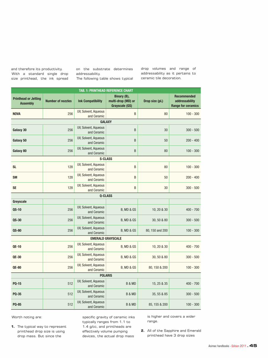
Acimac handbooks - Edition 2011 . 45
and therefore its productivity. With a standard single drop size printhead, the ink spread
on the substrate determines addressability. The following table shows typical
drop volumes and range of addressability as it pertains to ceramic tile decoration.
TAB. 1: PRINTHEAD REFERENCE CHART
Printhead or Jetting
AssemblyNumber of nozzles Ink Compatibility
Binary (B),
multi-drop (MD) or
Grayscale (GS)
Drop size (pL)
Recommended
addressability
Range for ceramics
NOVA 256UV, Solvent, Aqueous
and CeramicB 80 100 - 300
GALAXY
Galaxy 30 256UV, Solvent, Aqueous
and CeramicB 30 300 - 500
Galaxy 50 256UV, Solvent, Aqueous
and CeramicB 50 200 - 400
Galaxy 80 256UV, Solvent, Aqueous
and CeramicB 80 100 - 300
S-CLASS
SL 128UV, Solvent, Aqueous
and CeramicB 80 100 - 300
SM 128UV, Solvent, Aqueous
and CeramicB 50 200 - 400
SE 128UV, Solvent, Aqueous
and CeramicB 30 300 - 500
Q-CLASS
Greyscale
QS-10 256UV, Solvent, Aqueous
and CeramicB, MD & GS 10, 20 & 30 400 - 700
QS-30 256UV, Solvent, Aqueous
and CeramicB, MD & GS 30, 50 & 80 300 - 500
QS-80 256UV, Solvent, Aqueous
and CeramicB, MD & GS 80, 150 and 200 100 - 300
EMERALD GRAYSCALE
QE-10 256UV, Solvent, Aqueous
and CeramicB, MD & GS 10, 20 & 30 400 - 700
QE-30 256UV, Solvent, Aqueous
and CeramicB, MD & GS 30, 50 & 80 300 - 500
QE-80 256UV, Solvent, Aqueous
and CeramicB, MD & GS 80, 150 & 200 100 - 300
POLARIS
PQ-15 512UV, Solvent, Aqueous
and CeramicB & MD 15, 25 & 35 400 - 700
PQ-35 512UV, Solvent, Aqueous
and CeramicB & MD 35, 55 & 85 300 - 500
PQ-85 512UV, Solvent, Aqueous
and CeramicB & MD 85, 155 & 200 100 - 300
Worth noting are:
1. The typical way to represent printhead drop size is using drop mass. But since the
specifi c gravity of ceramic inks typically ranges from 1.1 to 1.4 g/cc, and printheads are effectively volume pumping devices, the actual drop mass
is higher and covers a wider range.
2. All of the Sapphire and Emerald printhead have 3 drop sizes

46 . Acimac handbooks - Edition 2011
www.dimatix.com
noted as they are designed for 4-level VersaDrop printing. The last level not indicated in this table is zero or no drop ejected and is a level that is required in all printing.
3. Addressability is defi ned by a range as different tile types will react to different inks resulting in different amounts of drop spread.
4. Grayscale printheads are usually based upon the largest drop size to defi ne the solid fi ll requirement.
In some cases it can also be associated with the next largest size allowing more coverage for light colors such as yellow, pink and white but generally require extra coverage.
For example, if the printing system
uses a QE-30 operating in single pulse binary mode at 40pl, the required addressability should be more like 300 - 500. However, using VersaDrop, the largest drop volume size of 80pl dictates the addressability which results in an addressability between 100 and 300 dpi. This fl exibility reduces the number of printheads required.
DETERMINING THE OPTIMAL PRINTHEAD
Determining the optimal printhead is the next step in the process.
Expanding upon the examples used thus far and using the values in Table 1, we can now defi ne the
inkjet tile decoration printing system design as follows:
TAB. 2: PRINTHEAD SOLUTIONS FOR CERAMIC TILE INKJET DECORATION
Printer
Dpi
Linear speed
Grayscale or
variable drop size
Y / N
Drop sizes
required
Printhead
possibilitiesNative dpi
Process
Direction
Cross
Process
400 400 50m/min Yes 30, 50 and 80
QS-30
QE-30
PQ-35
100
100
200
INK OPTIMIZATION
The fi nal step in the process is to ensure the ceramic ink formulation and printhead combination chosen will function according to the
specifi ed requirements. As this is another critical success factor. Dimatix supports this effort by working closely with the systems
integrator and the ink developer to provide focused efforts in waveform development, advanced materials analysis and technical fi eld support.
WAVEFORM DEVELOPMENT
A waveform is the electrical signal that actuates the piezo crystal to fi re the jet. Different waveforms create different drop sizes at varying drop velocities. Optimizing a waveform for each application ensures the highest level of success. All waveform development, whether for binary
single drop or multi- drop fi xed or grayscale requires information about the intended process. The key considerations include;
• Output mode, binary single drop, binary multi drop or Grayscale.
• Drop volume(s) required.• Printhead jetting frequency
defi ned by the linear speed and addressability.
• Ink operating parameters such as jetting temperature.
• Duty cycle defi ned as the

Acimac handbooks - Edition 2011 . 47
average amount of time each nozzle is running over a production run.
For ceramic tile decoration this could be as low as 10-20% but it could be 60-70% utilization for denser images.
The combination of printing frequency and duty cycle are important because this is the environment printheads are required to operate, and is how the combination of printhead
and ceramic ink should be tested.
Dimatix printheads have an open architecture that allows developers to employ waveforms of their own design and does not restrict jetting to fi xed waveforms for inks that may be under development.
Our technical staff provides fundamental training in waveform
development techniques to integrators and ink developers so that they can continue to evolve these waveforms on their own as changes to the ink formulation, printing system, or process is made. Initial jetting of a new ink formulation can start by using a Dimatix supplied reference waveform set these can then can be adjusted or further enhanced to meet new ink properties and requirements.
MATERIAL COMPATIBILITY
To ensure long printhead life under operating conditions, it is critical all ink and maintenance fl uids used within the printing system are compatible with the printhead selected. Dimatix supplies material test kits for this purpose. These kits are comprised of printhead components in sizes suitable for conducting ink immersion tests. Typically, at the conclusion of these tests, inspection of the printhead components occurs followed by bond strength pull tests.
Compatibility testing can be either conducted by the system integrator and ink developer or with the support of Dimatix’ analytical labs.
Additionally, components used within the ink delivery system should also be tested for compatibility as well. This is to ensure these materials will not decompose or swell up and cause blockages or leaks in the fl uid delivery circuit. With higher standoff jetting, misting of inks can cause a
buildup of ceramic ink all around the printhead and surrounding materials. It is important that testing include these components as well.
In summary, the process of choosing the optimal printhead requires knowledge of the application, addressability, drop spread estimates, understanding of the total error budget, and concludes with waveform development and ink compatibility testing to ensure the printhead and ink combination meets all of the requirements.
THE FUTURE OF CERAMIC TILE DECORATION
The adoption of inkjet printing for ceramic tile decoration has increased dramatically over the last several years. Driving this rapid growth are the recognized advantages only offered by digital solutions such as quick turnaround time, shorter run-length, customization, and supply chain reengineering possibilities. Behind these developments is a coordinated effort between ink developers, systems integrators and printhead manufacturers to quickly
address the current needs but with a view to the future.
Looking forward the question becomes-how will the ceramics market evolve? We believe there are three areas that hold great promise. These include continued improvement in system’s productivity, operability and greater fl exibility offered by new ink formulations. Over time, the current trade-offs in line speed versus color saturation
will become less acceptable as well as long start-up times and ongoing maintenance procedures that impact productivity. As this application matures beyond simple decoration to include spot glazing with the use of heavier pigment inks, ongoing technological developments will be required. Fujifi lm Dimatix will continue to bring its considerable expertise and extensive resources to bear to ensure the future and long-term success of this important market.

48 . Acimac handbooks - 2011 Edition
Inkjet technology in ceramic tile decoration
with the needs of the market.However, unlike in other sectors, in the ceramic industry the decorated surface is subject to high temperatures, evaporation, dimensional variations and above all a thermal fi ring process that completely alters its characteristics.In order to keep pace with recent and future developments in ceramic decoration and to deliver the most effective solutions to production requirements that are increasingly oriented towards digital technology, Ingegneria Ceramica, one of the largest producers of glazing and decoration systems, and Sacmi, the leading player in the ceramic plant manufacturing sector, have
The ceramic industry is currently experiencing a major technological revolution in terms of tile decoration. As has already occurred in the textiles and printed media industries, the ceramic industry has likewise developed and begun to adopt digital inkjet decorating machines, ceramic printers that are capable of overcoming the problems posed by this technology while offering numerous advantages to producers.This form of non-contact printing is able to decorate complex surfaces while allowing for more fl exible production management and a completely different storage rationale that is more consistent
decided to set up a joint venture company called In.Te.Sa. The fi rst step taken by In.Te.Sa. was to create its own digital decorating machine called Colora HD, a compact, high-defi nition ceramic printer with small dimensions to facilitate installation on ceramic production lines and to allow the machine to be delivered complete and ready for use.Colora HD adopts design criteria that aim to solve the typical problems associated with inkjet printing in the ceramic sector, such as condensation, vapour, dust, clogged nozzles and ink sedimentation.Colora HD uses Xaar 1001 printheads which operate according to Drop On Demand technology.
GENERAL CHARACTERISTICS OF THE TECHNOLOGY
by Davide Sorrentino, Mauro Bedini
Inkjet printing is a non-contact technology that decorates the substrate by emitting droplets of ink (6-42-80-200 pl, 1 pl=10-12 l) through tiny nozzles on the printheads. This form of printing can be performed in different ways, essentially in Continuous or Drop On Demand modes (fi gure 1).The mode that has achieved the best results in the ceramic industry is Drop On Demand.Drop On Demand technology, meaning that droplets can be generated precisely when required, can be based on different methods: heat, piezoelectric, electrostatic or acoustic. The method that has become established in the ceramic industry is that of piezoelectric actuators.
A piezoelectric element (“Piezo” in Greek means “pressure”) is a material that is capable of expanding or contracting when a specifi c electrical voltage is applied. The resultant movement allows the droplet of ink to be created and expelled. One of the most widely used piezoelectric materials is lead zirconate titanate, also known as PZT. Interestingly, the use of ceramic materials is also very widespread in the manufacture of piezoelectric elements (Figure 2).
Various types of printhead are available according to the required droplet formation method. They can be divided into four
Fig. 1
Fig. 2

Acimac handbooks - 2011 Edition . 49
categories: Squeeze-tube, Bend, Push and Shear (fi gure 3).The piezoelectric elements can be activated using different methods and sequences so as to produce a drop only when required.
A) In the Squeeze-tube method, two piezoelectric elements deform a suitably shaped tube.
B) In the Bend method the piezoelectric element undergoes an arc-shaped deformation so as to expel the drop.
C) In the Push method the piezoelectric element deforms and pushes the drop out through the nozzle.
D) In the Shear design the material is polarised in such a way that the electrical impulse generates a shear deformation.
In Shear mode the nozzles are positioned sequentially on the printhead plate. A row of nozzles performs printing at three different times. For the sake of simplicity, we can show an operating diagram indicating the 3 emission phases (photos 4 and 5).This latter case is that of the Xaar 1001 printheads used on Colora HD.
An important consideration concerns the ink supply to the printhead. Some printheads are equipped with accumulation chambers called dampers that ensure that the correct quantity of ink is available at all times during use. Although this type of printhead usually has a good jetting frequency and drop volumes, it has drawbacks relating to the capacity of the tank and the tendency of the solvent-based inks used in the ceramic industry to sediment when not in use. To avoid this problem, the printheads must be regularly purged by performing non-productive printing cycles. Other types of printhead have a design that allows for continuous recirculation of the ink inside their structure. This prevents sedimentation and assures a consistent and continuous supply of ink, thereby overcoming the limitations imposed by the internal damper. However, to operate
Fig. 3
Fig. 4
Fig. 5
correctly these printheads must be supplied with ink by a more effi cient system equipped with a delivery and return circuit that not only allows the ink to be kept continuously moving but also guarantees the pressures, fl owrates and temperatures required for correct drop formation.
In addition to the above-mentioned parameters, the supply circuit must also control the meniscus (fi gure 6), i.e. the position of the ink in the nozzle zone. To avoid printing problems, the ink pressure must be carefully controlled and maintained at a slightly negative value in this zone. Excess pressure may lead to incorrect drop formation, causing drops to fragment during jetting and deposit incorrectly on the surface of the printheads and the print table. The opposite situation, i.e. excessively negative pressure, may create droplet formation diffi culties resulting in the presence of banding or serious loss of detail in the image.
The solution proposed by Colora HD is based on a circuit designed to guarantee correct ink supply over time and equipped with a user interface that is easy to use and set up (photo 7 and 7bis ).The ink supply system is also responsible for accurate operating temperature control (normally between 37°C and 45°C). It must be possible to heat the ink rapidly and maintain it at a constant temperature. Inadequate temperatures may create printing problems due to incorrect drop formation and variations in the ink’s rheological characteristics. Furthermore, incorrect operating temperatures may lead to sedimentation inside the circuit. For this reason, Colora HD is designed in such a way as to prevent the occurrence of problematic sedimentation phenomena by avoiding angular-shaped tanks or distributors and ensuring that inks
Fig. 6
Fig. 7
Fig. 7 bis
are constantly agitated.
However, these precautions are not suffi cient and it is important to ensure collaboration between ink suppliers and plant manufacturers.At present there are three main families of inks which differ essentially in terms of their constituent organic mixtures, which together with the additives and mixtures of pigments used determine their rheological characteristics. The importance of control and management of the functional parameters of the inks by their respective manufacturers is crucial for the quality, stability and continuity of printing. Photo 8 shows an ink analysis.
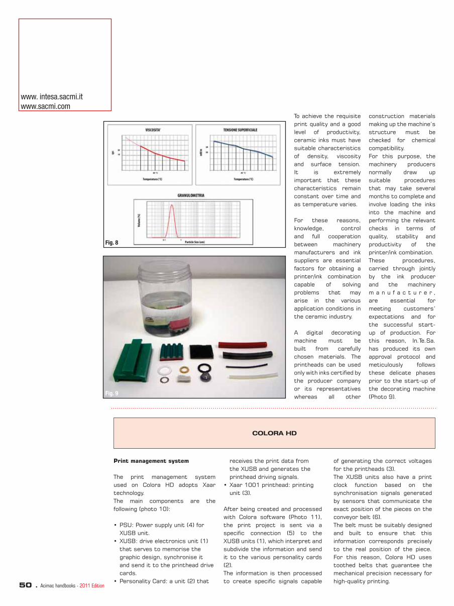
50 . Acimac handbooks - 2011 Edition
To achieve the requisite print quality and a good level of productivity, ceramic inks must have suitable characteristics of density, viscosity and surface tension. It is extremely important that these characteristics remain constant over time and as temperature varies.
For these reasons, knowledge, control and full cooperation between machinery manufacturers and ink suppliers are essential factors for obtaining a printer/ink combination capable of solving problems that may arise in the various application conditions in the ceramic industry.
A digital decorating machine must be built from carefully chosen materials. The printheads can be used only with inks certifi ed by the producer company or its representatives whereas all other
construction materials making up the machine’s structure must be checked for chemical compatibility. For this purpose, the machinery producers normally draw up suitable procedures that may take several months to complete and involve loading the inks into the machine and performing the relevant checks in terms of quality, stability and productivity of the printer/ink combination.These procedures, carried through jointly by the ink producer and the machinery m a n u f a c t u r e r , are essential for meeting customers’ expectations and for the successful start-up of production. For this reason, In.Te.Sa. has produced its own approval protocol and meticulously follows these delicate phases prior to the start-up of the decorating machine (Photo 9).
Fig. 8
Fig. 9
COLORA HD
Print management system
The print management system used on Colora HD adopts Xaar technology.The main components are the following (photo 10):
• PSU: Power supply unit (4) for XUSB unit.
• XUSB: drive electronics unit (1) that serves to memorise the graphic design, synchronise it and send it to the printhead drive cards.
• Personality Card: a unit (2) that
receives the print data from the XUSB and generates the printhead driving signals.
• Xaar 1001 printhead: printing unit (3).
After being created and processed with Colora software (Photo 11), the print project is sent via a specifi c connection (5) to the XUSB units (1), which interpret and subdivide the information and send it to the various personality cards (2).The information is then processed to create specifi c signals capable
of generating the correct voltages for the printheads (3). The XUSB units also have a print clock function based on the synchronisation signals generated by sensors that communicate the exact position of the pieces on the conveyor belt (6). The belt must be suitably designed and built to ensure that this information corresponds precisely to the real position of the piece. For this reason, Colora HD uses toothed belts that guarantee the mechanical precision necessary for high-quality printing.
www. intesa.sacmi.it
www.sacmi.com

Acimac handbooks - 2011 Edition . 51
Fig. 10 Fig. 11
Waveform and drop formation
As we have said, the drop is formed by applying a suitable voltage waveform to the piezoelectric elements.A waveform is the variation over time of the electrical voltage applied to the printhead. In general there are many different types of waveform, such as sine wave, square, ramp, sawtooth and triangular (photo 12). One frequently used waveform is the square wave, where the signal has a positive value for a given time and a value of zero for an identical period of time. In this case the duty cycle is 50%. This kind of waveform is widely used in electronic circuits as a clock signal. If the duty cycle is not 50%, in other words the duration of the positive signal is different from the duration of the zero signal, the waveform is said to be rectangular.A variant of these two waveforms is that of the pulse, in which a short interval with a positive signal alternates with a longer interval with zero signal (photo 13).These examples are the basic waveforms generated by the control electronics to drive the piezoelectric elements of the printheads.Using these pulses it is possible to obtain different drop volumes suited to the various ink formulations. One of the areas in which the
players involved in developing digital decoration systems have concentrated their efforts is that of identifying waveforms capable of correctly forming the drop. Whereas printheads operating in binary mode generate a single type of large drop, printheads operating in greyscale modulate the emission frequency in such a way that it is possible to obtain a larger drop from the combination of the various subdrops. For example, the Xaar 1001 printheads used on Colora HD use a basic droplet of 6 pl to create the various levels (eight including non-emission). These subdrops then combine as they travel through the air to form a single drop with a size of up to 42 pl (photo 14). The use of the correct number of grey levels requires an optimisation process that must take account of variables such as print quality, the desired intensities and productivity. For these reasons, in the ceramic sector these issues have been addressed in cooperation with the ink manufacturers so as to create suitable waveforms for optimising production. The choice of waveform is determined by the technological characteristics of ceramic materials. The fi ring process often causes lower intensities
consisting of low-volume drops to disappear. Moreover, the tendency of these drops to be highly volatile makes it diffi cult to use them continuously. Furthermore, by developing appropriate waveforms it is possible to simplify important aspects such as operating stability with respect to changes in applied voltage: a suitable waveform may allow an ink to operate with the same quality over a voltage range of ± 3 volt. Moreover, the use of high greyscale levels corresponding to small drop volumes may give rise to phenomena that adversely affect print quality and the productivity of the decorating machine/ink combination. It is essential to study these phenomena. The instrument normally used is the Drop Watcher (photo 15), a microscope equipped with a stroboscope that is able to photograph the drops
Fig. 12
Fig. 13
Fig. 14Fig. 14

52 . Acimac handbooks - 2011 Edition
during their movement and to determine the jetting frequency, the angle of ejection and effective volume. This instrument provides useful information on correct droplet formation (desired volume, correct trajectory and the absence of defects such as satellites or mist which would cause print defects, etc.).
As we have said, a greyscale drop is formed as it travels through the air. The subdrops combine as they travel to form a single drop of larger dimensions (Photo 16). At a certain point these drops take on their fi nal form and the occurrence of formation problems would create undesirable trails with droplets ending up off-trajectory, resulting in a severe decline in quality. These drops are called satellites (Photo 17).The fi rst step is to analyse printing with the different inks to assess linearity, dimensional uniformity and the presence of satellites while altering the application parameters such as waveforms and voltages for the same applied temperature or meniscus (Photo 18).
Correct behaviour of the inks can also be determined
Fig. 15 Fig. 16
Fig. 17Fig. 17
Fig. 18Fig. 18
Fig. 19Fig. 19
www. intesa.sacmi.it
www.sacmi.com
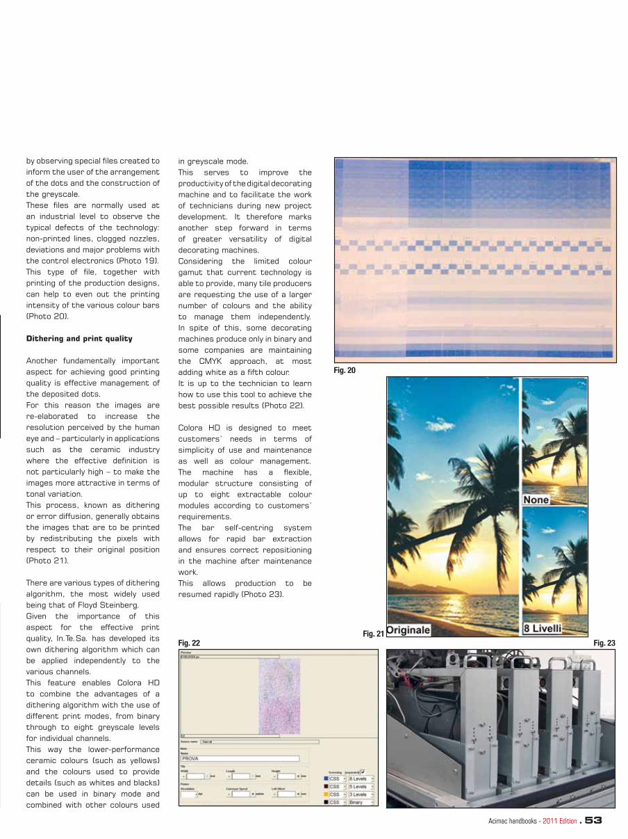
Acimac handbooks - 2011 Edition . 53
in greyscale mode. This serves to improve the productivity of the digital decorating machine and to facilitate the work of technicians during new project development. It therefore marks another step forward in terms of greater versatility of digital decorating machines. Considering the limited colour gamut that current technology is able to provide, many tile producers are requesting the use of a larger number of colours and the ability to manage them independently. In spite of this, some decorating machines produce only in binary and some companies are maintaining the CMYK approach, at most adding white as a fi fth colour. It is up to the technician to learn how to use this tool to achieve the best possible results (Photo 22).
Colora HD is designed to meet customers’ needs in terms of simplicity of use and maintenance as well as colour management. The machine has a fl exible, modular structure consisting of up to eight extractable colour modules according to customers’ requirements. The bar self-centring system allows for rapid bar extraction and ensures correct repositioning in the machine after maintenance work. This allows production to be resumed rapidly (Photo 23).
by observing special fi les created to inform the user of the arrangement of the dots and the construction of the greyscale. These fi les are normally used at an industrial level to observe the typical defects of the technology: non-printed lines, clogged nozzles, deviations and major problems with the control electronics (Photo 19).This type of fi le, together with printing of the production designs, can help to even out the printing intensity of the various colour bars (Photo 20).
Dithering and print quality
Another fundamentally important aspect for achieving good printing quality is effective management of the deposited dots. For this reason the images are re-elaborated to increase the resolution perceived by the human eye and – particularly in applications such as the ceramic industry where the effective defi nition is not particularly high – to make the images more attractive in terms of tonal variation.This process, known as dithering or error diffusion, generally obtains the images that are to be printed by redistributing the pixels with respect to their original position (Photo 21).
There are various types of dithering algorithm, the most widely used being that of Floyd Steinberg. Given the importance of this aspect for the effective print quality, In.Te.Sa. has developed its own dithering algorithm which can be applied independently to the various channels.This feature enables Colora HD to combine the advantages of a dithering algorithm with the use of different print modes, from binary through to eight greyscale levels for individual channels. This way the lower-performance ceramic colours (such as yellows) and the colours used to provide details (such as whites and blacks) can be used in binary mode and combined with other colours used
Fig. 20
Fig. 21Fig. 22 Fig. 23

54 . Acimac handbooks - 2011 Edition
The production stage
Printing quality in the ceramic industry is infl uenced by the material’s unique technological character i st i cs . The substrates to be decorated may have characteristics that make them very diffi cult to treat. For example, green tiles leaving the dryer have temperatures of around 100-110°C, decreasing as the tiles move along the line. The application of glazes, screen printing decorations and the transport systems make these temperatures necessary to prevent the tile bodies from breaking during transit. The digital printing machine is normally located in a zone where the tiles reach temperatures of between 50°C and 60°C. These temperatures are not ideal for good printing as after a few minutes of production they are liable to give rise to severe condensation, or even worse, nozzle plate contamination. All digital decorating machine producers advice setting up the line in such a way that the tiles arrive at the machine infeed at temperatures in the region of 45°C to considerably reduce the ∆t between the tile and the print table.
Colora HD’s ability to control the temperature of the print table and the ink by means of the sensors present in the delivery and return circuits and in the print table allows for optimal management of machine performance.
Furthermore, traditional decoration applications involve formulations that include the presence of water (e.g. engobes, glazes, screen printing pastes, etc.).This water is subject to evaporation, which, due to the non-polar nature of ceramic inks and the characteristics of the printheads, may give rise to problems such as banding, interruption of printing or damage to electronics.It is therefore necessary to prevent evaporation. Fans, intakes and dryer exit temperature regulation are important tools that can help to reduce this kind of problem (Photo 24).
For the same reason, additive producers have developed primers capable of temporarily preventing evaporation from the tiles. Some companies have also proposed various methods (air conditioning, water, etc.) for temporarily reducing the surface temperature of the tile bodies.
The machine is fi tted with useful features such as extraction systems on the print table. The purpose of this is to isolate the colour bars so as to avoid contamination between incompatible colours and to prevent nebulised vapours/inks from depositing on the print table and forming droplets that might make it necessary to halt production. Colora HD has its own system for extraction between the bars that is specially designed to minimise the above-mentioned problems.
During production, impurities inevitably tend to deposit on the print table over time and eventuality affect the quality of decoration. These impurities must therefore be removed by means of suitable cleaning procedures. Colora HD
offers a fully automatic, user-settable system capable of achieving the quality standards required by customers (Photo 25).
Another fundamental aspect for achieving the requisite application conditions and for maintaining the functionality of the digital decorating machine over time is that of controlling the environment in which the machine is installed.Digital decoration is susceptible to the infl uence of dust and humidity. Dust can clog the printhead nozzles externally and create problems with the printing electronics, while humidity can create problems due to the incompatibility between inks, printheads and water (Photo 26). For these reasons, correct environmental conditions are essential and the only way of maintaining them is to install the machine inside a purpose-designed cabinet. The atmosphere inside the cabinet should preferably be air conditioned to guarantee optimal levels of temperature and humidity, and a slight positive pressure should be maintained to prevent dust from entering the cabinet. This kind of solution is widely used in manufacturing facilities the world over (Photo 27).
Undesired contact between the tiles and the printheads may lead to deformations and/or clogging of the nozzles, irreversibly deviating the trajectory of the ink drops. A frequent occurrence during production is the overlap of tiles which may damage the print table as they advance. For this reason, a number of manufacturers include specifi c protection systems. Colora HD is equipped with a system for detecting overlapping tiles that when necessary causes the print unit to lift temporarily without halting production.
Correct start-up begins with correct positioning of the digital decorating machine on the line. In.Te.Sa. is able to support customers at all stages of introducing Colora HD into the
Fig. 24Fig. 24
Fig. 25Fig. 25
Fig. 26Fig. 26
Fig. 27Fig. 27
Fig. 28Fig. 28
www. intesa.sacmi.it
www.sacmi.com

Acimac handbooks - 2011 Edition . 55
NOTE
production process. Meeting market needs also means decorating large-format tiles. For this reason, Colora HD is also available with printing widths of 900 mm, 1400 mm and 1700 mm (Photo 29).
Production management also involves the use of colour management systems that support customers through all stages of the production process, from conception through to quality control. For this purpose, In.Te.Sa. offers a proprietary system called CRONO (see the article published on page 4).
Fig. 29

56 . Acimac handbooks - 2011 Edition
Advantages of digital printing in the ceramic decoration
process of previously used glazes and screen printing pastes, which are replaced by 3, 4 or 5 base colours, as well as the screens, rollers and transducers used to transfer images in traditional technology. This results in both logistic and economic benefi ts given the absence of component wear and the waste and obsolescence of the screen printing pastes used in the past.
Speed of product changeover: with these printing systems it is possible to change product type in under two minutes, provided other applications on the line do not need to be modifi ed. This leads to a reduction in the minimum batch size without sustaining higher production costs and resulting in the maximum production plant fl exibility.
Higher productivity due to the intrinsic characteristics of printing technology such as speed, reproducibility and stability. The fi rst choice percentage that can be achieved with this technology is extremely high. Naturally the chosen printing system must consider the high speed on the decoration line so as not to risk a falloff in productivity.
Low operating costs: using the printing system in accordance with the manufacturer’s specifi cations allows maximum production effi ciency to be maintained along with low maintenance costs. In particular, the temperature of the item to be printed must be kept within an established range so as to avoid an
The introduction of digital printing has brought a number of benefi ts for the ceramic decoration process. While initially noted for its aesthetic results, the real strength of this innovation is now recognised as being its ability to cut costs through production control and fl exibility. But what are the advantages of digital printing over traditional decoration?
Non-contact printing: this characteristic makes it possible to print on textured surfaces and over previous applications without having to take account of these applications or the humidity of the surface.
Digital quality of images: the introduction of ever higher performance printing systems and new inks capable of expanding the available colour space has allowed for the increasingly realistic reproduction of designs such as natural stone and wood.
Graphic design development: the possibility of creating a considerable number of images per project and the uniqueness of products are characteristics that cannot be achieved with traditional technology.
Speed of development and reproducibility of products that was unimaginable prior to the introduction of digital technology.
Tone stability resulting in reduction in warehouse stock.
Simplifi cation of logistics in terms
excessive number of stoppages to reset the system. Furthermore, the formation of condensation in the lower part of the piezoelectric element due to the temperature differential between the printing unit and the tile may over time damage the nozzles of the piezoelectric element. The hygroscopicity of the inks must also be considered as the ink’s tendency to incorporate water can cause serious problems. The temperature and vapour levels must therefore be kept within the values specifi ed by the manufacturer.
Low ink consumption: with the aid of effective colour management systems it is possible to optimise consumption so as to create the widest range of products using just a few grams of ink per square metre.
For more than ten years, Kerajet has been working towards the introduction of digital decoration in the ceramic production process. The know-how passed on to its customers derives from ongoing research into all aspects of the digital printing process, including printing systems, inks, colour management software, technical support and graphic design. The experience and expertise it has gained enable the company to develop proprietary or integrated solutions for the utmost freedom and customisation, thereby delivering fl exible solutions that meet real production requirements. The 270 completed digital installations demonstrate the effectiveness of the proposed solutions.
by Alberto Ghisellini
COLOUR MANAGEMENT
Colour management is an aspect of the utmost importance for printing. But unlike traditional graphic arts printing, ceramic decoration is followed by a fi ring stage that can alter the colour rendering of pigmented inks.The colour space available for
reproducing an image is therefore very limited.
The image 1 shows two gamuts. SRGB is the wider colour space normally used in graphic arts, whereas the much narrower gamut is that of a three-colour ceramic profi le.
In image 2 too, the gamut of a multicolour ceramic profi le (C Br P Y Bg) is very limited compared to the Adobe RGB colour space.
In image 3, comparing the CMYK colour space available for paper
Fig. 1
Acimac handbooks - 2011 Edition . 57
printing with a ceramic three-colour space, the limits of reproducibility of certain colours are very evident. Furthermore, the wide degree of variability in the ceramic production process hinders photographic reproducibility.This variability arises from the fact that there are a number of factors in ceramic production that are diffi cult to maintain constant, including substrate composition, glaze formulation and quantity, and fi ring cycle.
SUBSTRATE
All the materials in the body are diffi cult to control in terms of nature, characteristics and quantities. Even introducing strict controls it is diffi cult to maintain them constant over time, which jeopardises product reproducibility (fi g. 4).
PRE-PRINTING APPLICATIONS
Here too it is diffi cult to keep their formulation constant. Components
are often changed for both technical and commercial reasons, and variations in these applications considerably impacts the end result of printing (fi g. 5).
FIRING CYCLE
This phase is very important for the colour development of the inks used in digital decoration, and even small differences in temperature or fi ring times can lead to considerable variations in colour (fi g. 6). Further potential variables include confi guration and colour sequences, ink suppliers, glazing line speed and printing parameters. To be able to manage all these variables successfully it is necessary to correctly identify the current situation by associating a specifi c profi le with a given time.
The ceramic profi le is therefore a precise picture of a given situation that considers all the above-mentioned variables (fi g. 7).
The profi le is generated by printing a chart (consisting of base colours and their combinations) that respects the colour sequence, the belt speed and the other printing parameters. This must be done using the body, glaze and engobe effectively used at that given time and performing a real fi ring cycle.The patches that make up the chart are subsequently measured using a spectrophotometer and the measured colorimetric data are processed by a software package capable of generating an ICC profi le. The ICC profi le of the RGB fi le (e.g. the fi le of a stone surface) and the generated profi le are processed by an additional software converter that also offers a preview of the result that can be achieved. At this stage the designer can make any necessary changes using Photoshop, avoiding the need for numerous costly trial runs.
WORKFLOW
The use of a correct workfl ow, tools
and colour management software together with reliable, high-performance printers enables Kerajet to deliver high-quality printing and reproducibility (fi g. 8) and to:
• Standardise the various sizes• Standardise the various products
(double fi ring, single fi ring, porcelain tile)
• Standardise the various types of printer
• Replace ink suppliers• Increase the colour modules• Reduce ink consumption to create
the same graphic design.
Fig. 2
Fig. 3
Fig. 4
Fig. 5
Fig. 6
Fig. 7
Fig. 8
Glaze
Engobe
Salting
Glaze
Engobe
SaltingPrinting:
belt speed
longitudinal resolution
colour sequence
Salting
Firing cycle

58 . Acimac handbooks - 2011 Edition
www.kerajet.it
• lower ink consumption• product reproducibility• guaranteed correct use of
the printing system without approximations thanks to a professional colour management technology
• production control and management.
This enables the maximum benefi t to be obtained from the characteristics of speed, productivity and versatility of digital systems such as those of Kerajet. The system can be applied to all inks, bodies, glazes, etc.
KERAJET PROPOSALS FOR COLOUR MANAGEMENT
Kerajet-ColorStore colour management systems can drastically cut times, resources and materials previous used for testing. Just a few actions are required to send a set of graphic images to production.This is largely a result of the reliable colour proofi ng system. What is viewed on the monitor or printed on paper is very similar to the fi nal result after fi ring. This means it is suffi cient to perform a colour proof following corrections to the graphic design without having to actually perform decoration and
fi ring each time.
The Kerajet-ColorStore colour management systems allow for:
• maximum exploitation of the colour properties of inks
• signifi cantly higher quality• total control over colours• higher productivity• high performance speed and
versatility (print on demand)• considerably shorter processing
times and fewer waste materials• fewer print proofs and fi ring
operations
KERAPROFILER AND KERACONVERTER
• better colour separation of the designs
• high-quality colour profi les• possibility of faithfully simulating
the end result subsequent to fi ring on the monitor (soft-proofi ng) and on paper (hard-proofi ng)
• possibility of making further colour corrections/adjustments directly on the separated graphic fi le with the use of post-fi ring simulation
• a signifi cant reduction in materials and times needed during intermediate tests.
The main advantages of KERAconverter are:
• the possibility of converting previous production runs (including those performed with traditional systems) to digital systems subsequent to verifi cation of original graphic fi les,
• use of a proprietary conversion engine and rendering intents specifi cally designed for ceramic inkjet systems.
Profi le management
KERAprofi ler can be used to
KERAprofi ler and KERAconverter are software packages designed for creating specifi c colour profi les for ceramic inkjet printing systems and for the conversion and separation of
graphic designs used in the ceramic sector.KERAprofi ler and KERAconverter give ceramic companies, graphic design fi rms and glaze and colour producers the opportunity to create colour profi les with complete autonomy.The software packages are based on colour libraries created exclusively with ceramic inks for Kerajet printing machines using an exclusive conversion engine. This allows for the maximum colorimetric quality during the separation of designs for ceramic printing.Colour profi les are based on the ICC standard so as to fully exploit advantages such as faithful simulation on both monitor and paper, the end result subsequent to fi ring, the possibility of making further colour corrections to already separated designs, a signifi cant reduction in printing proofs, etc.
The main advantages ofKERAprofi ler are:
• autonomous creation of colour profi les
• maximum colour rendering of the inks used
Fig. 9
Fig. 10

Acimac handbooks - 2011 Edition . 59
generate colour profi les based on the ICC standard for various types of printing:
• Three-colour• Four-colour• Multicolour (with and without black as base
colour and only for the Multicolor RIP Tiffout module).
KERAprofi ler is also able to generate prevalently four-colour profi les on the basis of spectral data obtained from third-party software or from ICC colour profi les generated with other software.In this latter case, KERAprofi ler does not edit the existing profi le but simply extrapolates the existing spectral data contained in the ICC profi le and then generates the profi le according to its own algorithms (fi g. 9 and 10).
Testcharts and testchart reading
KERAprofi ler generally uses proprietary testcharts for reading spectral data.These testcharts were developed mainly for X-RIte EyeOne iO® reading systems and are available for both single patch and strip mode reading. This latter mode is an important innovation as it allows a testchart to be read in under 3 minutes. This function is available only for dedicated ColorStore testcharts included in the software (fi g. 11).
Colour libraries
KERAprofi ler uses different colour libraries according to the type of graphic design and colour and type of base glaze. It is a well-known fact that one of the main characteristics of ceramic printing is that base glazes of different colour and intensity are used according to the type of product to be produced.This leads to colour quality problems during graphic design conversion, the problems becoming more serious the further the base glaze deviates from theoretical “paper white”.Specifi c settings that can be customised during profi le generation allow KERAprofi ler to take account
Fig. 11
of factors liable to infl uence the quality of the end result and thereby guarantee the maximum colour fi delity according to the inks and the base glaze used (fi g. 12).
Black channel (K) generation
Like all four-colour profi le generation software packages, KERAprofi ler has the functions and parameters necessary for black channel (K) generation. The classic commands for black ink management are therefore available, such as: K-Max, K-Min, TAC, GCR, etc. (fi g. 13).
Conversion management
KERAconverter allows for optimal management of all parameters necessary for performing a colour conversion from an RGB or CMYK source space to a CMY or CMYK output space.
These include:• Confi guration name• Path of folder where converted
designs are saved• Defi nition of RGB and CMYK
source spaces• Maintaining any incorporated
profi les• Defi nition of output space• Black point compensation• Embedded profi le• Rendering intent.
The converted graphic fi les are automatically saved in a folder set by the user.It is possible to create an infi nite number of conversion confi gurations and to have 8 conversion slots in the main window.
Product conversions
One of the important functions of KERAconverter is to convert or adapt products already created with other inkjet technologies. This is very useful when changing ink supplier or printhead technology (e.g. from binary to greyscale), or when it is necessary to repeat a product made in the past with a
Fig. 12
Fig. 13
Fig. 14

60 . Acimac handbooks - 2011 Edition
completely different machine from the one that is to be used for the new production run.T h i s f unct i on is subject to a number of
constraints that must be taken into consideration, including colour model, original graphic designs, difference between old and new inks, differences between old and new machines (fi g. 14 and 15).
RIP Tiffout
Rip Tiffout is a postscript RIP designed by ColorStore exclusively for the ceramic inkjet printing sector and is able to generate 1 Bit halftone fi les for exclusive use with Kerajet plotter printers. Thanks to the use of proprietary screens, Rip Tiffout converts the continuous-tone graphic tiles to 1 Bit halftone fi les to ensure correct printing with the various Kerajet
solutions. Rip Tiffout is a modular type RIP, i.e. it offers the opportunity of integrating a number of modules with the
standard version according to each company’s specifi c requirements.Some of these modules are innovative solutions for the ceramic sector, such as the Multicolor and Tone Tuner module (fi g. 16).
Multicolor
The RIP’s Multicolor module is a major innovation in the ceramic inkjet printing sector in terms of multicolour printing. The main advantage of this module is
www.kerajet.it
Fig. 15
Fig. 16
the capability of managing multicolour printing in-machine while maintaining the graphic fi les in CMY or CMYK mode. It does not use a Spot Color or Multichannel type mode as these colour management modes tend to be highly problematical.The Multicolor module uses the same print driver technology as normal paper inkjet printers or plotters. They have from 5 to 12 colour cartridges but the graphic fi les are maintained in RGB or CMYK thanks to the print driver responsible for separation of the various colours. This is a fundamental aspect in a workfl ow for ceramic inkjet printing systems. Keeping the graphic fi les in CMY or CMYK mode means maintaining all the benefi ts and advantages of a colour management system based on ICC profi les.Furthermore, the fact that 6 inks are used for printing means that the operator does not have to make any adjustment during either profi le generation or graphic design management.The only difference for the graphic design operator is that a much wider colour space is available, giving much greater margins for colour correction of converted graphic fi les and greater creative freedom.
Linearizzazione
The linearisation module is contained in some print drivers for Kerajet printers. It is a tool for calibrating ceramic printers or plotters and is essential for optimising the printer and the workfl ow as it is able to place the printer in a known and repeatable state. This is a signifi cant factor for maintaining process stability, reconversion and remote proofi ng.
Remote Proofi ng
The Remote Proofi ng function has always been part of the linearisation module and is used to standardise two or more printers, for example to ensure that two or more printers (possibility with the same characteristics) deliver the same
colour results during printing, or to standardise two production runs on the same printer.
Cost Manager
Cost Manager is a module that is capable of calculating ink consumption and cost per square metre of any project prior to printing. The Cost Manager module takes account of all the parameters set by the user and required for the calculation (number of colours, resolution, cost of colour per kg, etc.).
Tone Tuner
Intended mainly for production purposes, Tone Tuner is able to rapidly resolve tone variation problems that arise during production. It is suffi cient to establish a correction value and the RIP generates 11 different tonal versions of the graphic design.The tonal modifi cation corresponding to the reference is applied to a single face or all faces of the design, depending on requirements. This module is also very useful for graphic design operators in the intermediate proof stage, allowing them to rapidly perform colour centring of a given reference sample or obtain an immediate response in a process of tonal variation.
KERAverifi er
This module is an invaluable tool for checking the stability of the production process (fi ring, glaze, etc.). The procedure is quick to perform and involves reading two small test strips to check for variations in the production fl ow. The KERAverifi er module provides all the necessary colorimetric data and the corresponding colour variations. In this case it is easy to determine what has changed from one print to another or from one production run to another.
KERAproofer
KERAproofer uses a normal plotter

Acimac handbooks - 2011 Edition . 61
or inkjet printer to make a paper printout of the graphic fi le intended for the ceramic inkjet printing. This provides an extremely accurate simulation of the end result of fi ring and the precise colour of the base glaze.This module is an essential tool for graphic design operators as it allows
them to save time in intermediate proofi ng and fi ring.The ceramic inkjet printer, glazed tiles and the fi ring kiln are not always available. It is not necessary to perform the inkjet print on the ceramic substrate until the paper print correctly simulates the desired result.
The KERAproofer module is available for various printer or plotter sizes, from 17” upwards, independently of the brand. It is also available in stand-alone mode for colour proofi ng on paper for companies that do not use Kerajet printers.
KERAJET PRINTING SYSTEMS
• K700X: single-step industrial printer for decoration of ceramic fl oor and wall tiles.
• K700S-K1000S: single-step industrial printer for decoration of ceramic fl oor and wall tiles.
• Pk200: multi-pass plotter for decoration of fi eld tiles and trim pieces and for creating prototypes.
• KF 1200 S: single-step and multi-pass industrial printer for large formats.
• SIDE PRINT: single-step industrial printer for vertical decoration of trim pieces.
• TEST JET: laboratory instrument for checking ink operation.
The main difference between the single-pass systems presented is their use of different print units, the XAAR 1001 and SEIKO GS II.This difference should be taken into consideration when choosing the most suitable system for printing requirements. While some characteristics are similar (such as dimensions, software, the possibility of interpreting a design in binary or greyscale mode, print quality, user interface, double row printing and
general functions), the systems offer different performances when decorating many products, especially where it is necessary to deposit a large quantity of ink or for high speeds on the glazing line, or when it is necessary to create a particularly intense product.This means that the higher performance printing system will not only be a good choice for the production of small sizes but will also offer a degree of freedom and greater opportunities in the decoration of large formats (fi g. 17 and 18).
Fig. 17
Fig. 18

62 . Acimac handbooks - 2011 Edition
The K700S and K1000S printers (SEIKO GS print units) allow for high-speed production and are able to deliver a suffi cient quantity of colour to create very intense products.
TECHNICAL CHARACTERISTICS
Printing technology: DOD (drop on demand)Variable drop volume: from 15 to 105 pl usable in binary mode (choosing a given drop volume to create a graphic design) or with 4 levels of
grey according to the intensity of the source fi leVariable printing width: from minimum printing width of 287 mm consisting of 8 printheads per colour module to maximum printing width of 1077 mm (K1000) consisting of 30 printheads per colour modulePossible confi gurations: From 3 to 5 independent colour modules with relevant feeding and recirculation circuits to allow for the use of 5 different coloursGraphic design management: Three-
colour, four-colour, multicolour depending on the colour modules installed on the machineMaximum printing length: 54,000 mm corresponding to graphic memory capacityTransversal printing defi nition: 360 dpi for each colour moduleLongitudinal print defi nition: varies according to piece infeed speed• 1016 dpi - 24 m/min. in binary
mode 30 pl or GS 3• 762 dpi - 31 m/min. in binary
mode 30 pl or GS 3
K700X PRINTER
www.kerajet.it
K700S - K1000S PRINTERS
Fig. 19
The K700X printer is suitable for installations with a moderate decoration speed on the glazing line and where a high level of colour deposition is not required.
TECHNICAL CHARACTERISTICS
Printing technology: DOD (drop on demand)Variable drop volume: from 6 to 42 pl usable in binary mode (choosing a given drop volume to create a graphic design) or with 4 levels of grey according to the intensity of the source fi leVariable printing width: from minimum printing width of 282 mm consisting of 4 printheads per colour module to maximum printing width of 705 mm consisting of 10 printheads per colour module
Possible confi gurations: From 3 to 6 independent colour modules with relevant feeding and recirculation circuits to allow for the use of 6 different coloursGraphic design management: Three-colour, four-colour, multicolour depending on the colour modules installed on the machineMaximum printing length: 54,000 mm corresponding to graphic memory capacityTransversal printing defi nition: 360 dpi for each colour moduleLongitudinal print defi nition: varies according to piece infeed speed• 864 dpi - 10 m/min. in binary
mode 42 pl or GS 4 (maximum deposition)
• 360 dpi - 24 m/min. in binary mode 42 pl or GS 4 (maximum
deposition)Maximum thickness of piece to be printed: 40 mmImage loading time: under 2 minutes for a fi le of length 10 m; this corresponds to the product change time provided the applications on the glazing line are not changed.Cleaning and ink recovery: • Automatic standby cleaning
system for print units with ink kept recirculating
• Automatic on-run printhead cleaning system taking less than 20 seconds
Inks used: Pigmented inks and soluble salts from various approved suppliersDimensions: 1,700 x 1,470 x 3,700 mm

Acimac handbooks - 2011 Edition . 63
• 554 dpi - 43 m/min. in binary mode 30 pl or GS 3
• 469 dpi - 50 m/min. in binary mode 30 pl or GS 3
Maximum printing speed: 70 m/min.Maximum thickness of piece to be printed: 40 mmImage loading time: under 2 minutes for a fi le of length 10 m; this
corresponds to the product change time provided the applications on the glazing line are not changed.Cleaning and ink recovery: • Automatic standby cleaning
system for print units with ink kept recirculating
• Automatic on-run printhead cleaning system taking less than
15 secondsInks used: Pigmented inks and soluble salts from various approved suppliersDimensions:• 1,700 x 1,470 x 3,700 mm
version K700S• 2,100 x 1,470 x 3,700 mm
version K1000S
Fig. 20 Fig. 21
Fig. 22 Fig. 23 - Pk200S, Seiko GS II printhead Fig. 24 - PK 200S Plotter
PK200S PLOTTER
The plotter Pk200S is the ideal solution for the production of trim pieces and accents. It is also able to faithfully simulate the working conditions of single-step printers, making it an important tool for research and development of products of any kind.
TECHNICAL CHARACTERISTICS
Variable drop volume: from 15 to 105 pl usable in binary mode (choosing a given drop volume to
create a graphic design) or with 4 levels of grey according to the intensity of the source fi leMaximum printable size: 800x1980 mm standard version; customisable with print table up to 1200x3600 mmConfi gurability: 6 print units with relevant feeding and recirculation circuits to allow for the use of 6 different colours Graphic design management: Three-colour, four-colour, multicolour depending on the number of colours installed on the machine
Productivity: varies according to desired print quality; e.g. 360 dpi x 508 dpi standard quality, 25 sq.m/hImage loading time: 1 min. for a 1980x800 mm fi le Cleaning and ink recovery: Automatic standby cleaning system for print units with ink kept recirculating Maximum thickness of piece to be printed: 150 mm Inks used: Pigmented inks and soluble salts from various approved suppliers. Dimensions: 3,200 x 1,800 x 1,200 mm

64 . Acimac handbooks - 2011 Edition
www.kerajet.it
PRODUCTION COMPARISONS
The following are some examples of the various products that can be
obtained with different printing sy-stems at various line speeds and the
corresponding colour deposition re-quired to create them.
Printing system used
Printer 360 dpi 360 dpi
Resolution Xaar 1001 Seiko GS
Print unit 4 colour modules 4 colour modules
Confi guration 4 moduli colore 4 moduli colore
Fig. 25 - Examples of products that can be obtained with a speed of 20 metres per
minute on the glazing line
Fig. 26 - Examples of products that can be obtained with a speed of 24 metres per
minute on the glazing line
NOTE
Fig. 27 - Examples of products that can be obtained with a speed of 32 metres per
minute on the glazing line
Fig. 28 - Examples of products that can be obtained with a speed of 40 metres per
minute on the glazing line

Acimac handbooks - 2011 Edition . 65

66 . Acimac handbooks - 2011 Edition
Innovative solutions for inkjet printing machines
digital printhead. This printhead was chosen fi rstly for its exclusive ink recirculation system and secondly because it offers the best graphic resolution for ceramic decoration media (360 dpi).Its use, together with a proprietary patented feeding system that is able to exploit the unique ink recirculation system, eliminates all problems relating to operation of the nozzles and consequent defects on the decorated surfaces. This eliminates both impurities (unfi ltered particles) and feeding gaps (air bubbles), guaranteeing a process of dynamic feeding and an unlimited ink fl ow, which is particularly useful when the printhead is subject to continued operating stress such as when
Projecta Engineering has developed a full range of products for digital decoration with the aim of exploring all the new creative horizons that this technology has opened up in terms of aesthetic product development. For this purpose, all the mechanical, electrical and electronic components with the exception of the digital printhead have been designed, developed and manufactured internally. This is the best way of retaining complete control over the printing process and ink management while developing systems capable of working with any type of ceramic product in terms of size and surface texture.
The heart of the system is the world-leading Xaar 1001 2-way
printing solid areas of colour.
The management software for the digital printhead control module is also proprietary, allowing its performance characteristics to be optimised for the ceramic sector. The machine is able to operate with variable volume droplets (“greyscale” mode) with 8 levels of between 6 and 42 picolitres. The greyscale system allows for the highest level of graphic defi nition. Projecta Engineering’s machines are currently built to enable operation with up to 6 colours (with the exception of the Digiplot plotter, which is available with up to 8 colours), but the software is ready to manage up to 12 colours.
by Francesco Casoni
THE RANGE OF PRINTERS
The system from Projecta Engineering is both integrated and open. It covers a broad range of sizes (it can be used to decorate tiles up to a width of 1120 mm) and integrates with other solutions (including the Digiplot plotter, the patented Compact and Compact Moving machines for trim pieces designed to handle complex geometries and surface textures, and the Ink Tester control system). Furthermore, a constantly evolving validation system means that the machine is compatible with all inks supplied by the leading glaze and colour producers on the market. It also offers enormous creative potential to graphic design fi rms, many of whom have adopted the Digiplot development system.
Keramagic 700 and Keramagic Maxi differ only in terms of their maximum printing widths. Keramagic Compact offers the same performance but with much smaller overall dimensions and a
Type of machine Maximum printing width (mm)
Keramagic 700 700
Keramagic Maxi 1260
Keramagic Compact 350
Keramagic Moving 350
Digiplot 1400 x 700
Ink-Tester 70
narrower printing width. Keramagic Moving was developed to decorate any kind of concave or convex surface thanks to the printhead tilt capability. Digiplot is a laboratory plotter that can faithfully reproduce the same print options as Keramagic using a single-pass print mode. Ink-Tester is a simple and reliable system for colour testing.
Keramagic also adopts other innovative software and hardware solutions that speed up and simplify maintenance operations, drastically reducing the overlap line effect, improving colour uniformity and eliminating the white line
defect typically caused by nozzle clogging.
Designed in accordance with the SITI-BT Group’s GREENERGY criteria, Keramagic uses a greyscale system together with feeding recirculation management to achieve considerable ink savings. Compared to its direct competitors, the machine has a considerably lower installed power and therefore lower energy requirements. This enables it to be fi tted with an uninterruptable power supply to overcome the risk of power failures, a solution that cannot be adopted on other digital machines.

Acimac handbooks - 2011 Edition . 67
KERAMAGIC
using a battery of fi lters. This digital printer has two main innovative features:
• the 360 dpi printing resolution, • the possibility of setting
the size of the drop at 8 levels of grey, thus achieving photographic printing quality with excellent shade contrast.
The standard used is four colour printing (CMYK), while the electronics and the software have been implemented for the use of printing modes with up to eight colours. In order to exploit the printer’s potential to the full, it was necessary to design and construct a powerful microcontrolled electronic system, a control
This inkjet digital printing machine adopts drop-on-demand technology specifi cally designed for printing on ceramic tiles using pigmented and non-pigmented inks and non-water-based solutions and suspensions. The basic principle that makes this printer especially effective for printing on ceramic tiles is that the ink or colour is kept constantly in circulation through the printhead, allowing the ink to keep out anything that might block the individual nozzle (polluting particles, agglomerates and air bubbles), thus helping to maintain the suspension and avoiding and/or drastically reducing unnecessary production shutdowns. This circulation is obtained using a specifi c hydraulic system, and the polluting particles are eliminated
KERAMAGIC: TECHNICAL SPECIFICATIONS
Resolution 360 dpi cross-section (physical); longitudinal 360 dpi at 24 m/min.
Printing speed from 1 to 48 m/min. (with resolution of 360 dpi and 8 grey levels the maximum speed is 24 m/min)
Type of printing standard four colour or multicolour drop-on-demand inkjet
Grey levels 8 levels
Printhead make and model Xaar 1001
Belt transport brushless motor with optical encoder and reducer with zero backlash
Head height and movement control stepper motor
Motor control driver programmable intelligent digital
Power supply 400 Vac three-phase 50Hz+N+E
Required power 5 kW at 400 Vac
Compressed air fi ltered min. 6 bar
Belt width 750 mm
MATERIALS
Loadbearing structure mixed, painted carbon steel and AISI 304 stainless steel
Belt movement structure AISI 304 stainless steel
Conveyor belt acid-resistant polyurethane with polyester/aramid composite
Colour tray carbon steel and RAL 7035 painted iron
Feet and supporting structure AISI 304 stainless steel
Protective casing polycarbonate and AISI 304 stainless steel
Electric boards AISI 304 stainless steel with IP56/65 protection rating
OVERALL DIMENSIONS (APPROXIMATE)
Length 3600 mm (up to 4 colours); 4100 mm (up to 6 colours)
Width 1700 mm
Height 2200 mm
Weight 1300 kg
Fig. 1 - Keramagic
Fig. 2 - Keramagic for large sizes
Fig. 3 - Keramagic for large sizes

68 . Acimac handbooks - 2011 Edition
www.siti-bt.com
KERAMAGIC COMPACT AND KERAMAGIC COMPACT MOVING
Digital inkjet printing machines with drop on demand technology, delivering the same technical and design characteristics and performance as KeraMagic. Keramagic Compact is specifi cally designed for printing on small-size ceramic tiles such as skirtings, borders and accents. The special version KeraMagic Compact Moving was developed for printing on trim pieces and non-fl at surfaces. In a single pass it is able to decorate bullnoses, rounded
software with an operator interface and a simple mechanical system, all designed to allow the KeraMagic to provide outstanding technical performance while at the same time
making it extremely easy to operate.
Standard versions
• KeraMagic KM700: print
width from 70 to 700 mm, 10 printheads per colour.
• KeraMagic KM1120: print width from 70 to 1120 mm, 16 printheads per colour.
liners, etc. The printheads can be shifted in order to adjust the spray angle to the surface of the piece, so the printhead can be moved as close as possible to the piece.
Standard versions
• KeraMagic Compact KMC210/4 expandable to KMC210/6
• KeraMagic Compact KMC280/4 expandable to KMC280/6
• KeraMagic Compact KMC350/4
KERAMAGIC COMPACT: TECHNICAL SPECIFICATIONS
Resolution 360 dpi cross-section (physical); longitudinal 360 dpi at 24 m/min.
Printing speed from 1 to 48 m/min. (with resolution of 360 dpi and 8 grey levels the maximum speed is 24 m/min.)
Type of printing standard four colour or multicolour drop-on-demand inkjet
Grey levels 8 levels
Printhead make and model Xaar 1001
Belt transport brushless motor with optical encoder and reducer with zero backlash
Head height and movement control stepper motor
Motor control driver programmable intelligent digital
Power supply 400 Vac three-phase 50Hz+N+E
Required power 5 kW at 400 Vac
Compressed air fi ltered min. 6 bar
Belt width 650 mm
MATERIALS
Loadbearing structure mixed, painted carbon steel and AISI 304 stainless steel
Belt movement structure AISI 304 stainless steel
Conveyor belt acid-resistant polyurethane with polyester/aramid composite
Colour tray carbon steel and RAL 7035 painted iron
Feet and supporting structure AISI 304 stainless steel
Protective casing polycarbonate and AISI 304 stainless steel
Electric boards AISI 304 stainless steel with IP56/65 protection rating
OVERALL DIMENSIONS (APPROXIMATE)
Length 2600/2800 mm
Width 1500 mm
Height 2200 mm
Weight 1000 kg
Picture below -
Keramagic Compact Moving

Acimac handbooks - 2011 Edition . 69
expandable to KMC350/6• KeraMagic Compact
KMC210/4/M expandable to KMC210/6/M
• KeraMagic Compact KMC280/4/M expandable to KMC280/6/M
• KeraMagic Compact
KMC350/4/M expandable to KMC350/6/M.
DIGIPLOT AND INK TESTER
Digiplot is a laboratory plotter that can faithfully reproduce the same print options as Keramagic using single-pass print mode. Ink Tester is a specifi c system for identifying the physical and chemical parameters of Inkjet colours.Thanks to the targeted use of a single printhead, this machine offers similar performance to machines used for industrial production, at an acceptable cost.
Both machines replicate the construction and design
characteristics of Keramagic (use of pigmented and non-pigmented inks, non-aqueous solutions and suspensions; ink or colour kept constantly circulating through the printing head, 360 dpi print resolution, possibility of managing drop size in 8 grey levels, electronics and software adapted for use of up to eight colour printing).
DIGIPLOT: TECHNICAL SPECIFICATIONS
Print area 700x1400 mm
Resolution 360 dpi
Printing speed Max. 15 m/min at 360 dpi and 8 grey levels
Type of printing standard four colour or multicolour drop-on-demand inkjet
Grey levels 8 levels
Printhead make and model Xaar 1001
Axes brushless motor with optical encoder
Head height and movement control stepper motor
Motor control driver programmable intelligent digital
Power supply 400 Vac three-phase 50Hz+N+E
Required power 3 kW at 400 Vac
Compressed air fi ltered min. 6 bar
MATERIALS
Loadbearing structure mixed, painted carbon steel and AISI 304 stainless steel
Table structure Aluminium
Protective casing polycarbonate and AISI 304 stainless steel
Electric boards painted carbon steel with IP56/65 protection rating
OVERALL DIMENSIONS (APPROXIMATE)
DG1400-700/4-6 colour DG1400-700/8 colour
Length mm 2410 mm 3250
Width mm 2100 mm 2100
Height mm 1180 mm 1180
Work table height mm 800 mm 800
Weight kg 1000 kg 1100
Dig
iplo
t

70 . Acimac handbooks - 2011 Edition
www.siti-bt.com
INKTESTER: TECHNICAL SPECIFICATIONS
Print area 70 mm
Resolution 360 dpi
Printing speed Max. 24 m/min at 360 dpi and 8 grey levels
Type of printing inkjet drop on demand single colour
Grey levels 8 levels
Printhead make and model Xaar 1001
Belt transport brushless motor with optical encoder and reducer with zero backlash
Belt width 220 mm
Head height and movement control manual
Motor control driver 230 Vac single-phase 50Hz + E
Power supply 1 kW at 230 Vac
Required power fi ltered min. 6 bar
COMPRESSED AIR
Supporting structure RAL 7032 painted carbon steel
Electrical board painted carbon steel with IP56/65 protection rating
OVERALL DIMENSIONS (APPROXIMATE)
Length mm 1500
Width mm 500
Work table height mm 1000
Weight kg 100
NOTE
Projecta Engineering laboratory

Acimac handbooks - 2011 Edition . 71

72 . Acimac handbooks - 2011 Edition
Process innovation, the key to digital technology
All process innovations are based on an analysis of the advantages and limitations of a new technology. We shall look at both. Advantages of digital technology include: • High print definition• Fast and cheaper prototyping• Decoration of textured surfaces• Graphic variability (number of
faces)• Flexibility in production
changeovers (small on-demand
Digital technology is developing constantly and has rapidly become the most advanced technique for ceramic decoration. At the present time, the goal of System Ceramics is to understand which aspects need to be focused on in order to optimise the technology’s productivity while pursuing continuous research into process innovation with a view to changing the parameters themselves.
batches).
The disadvantages or limitations of digital technology include: • Limitations in colour gamut• Limited deposition of material• Difficulties in rapid ink changing• Productivity/speed• Narrower working range
throughout entire production process
• Machine cost• Standardisation of finished product.
A comparison between conventional decoration technology (Rotocolor) and digital decoration technology reveals a number of differences which are worth examining.
choice percentages leaving the sorting stage. Digital technology still suffers from the problem of banding on the fi nished product, making it necessary to correct the software used by automatic vision and selection systems.
Tiles with banding visible at a distance of 35-40 cm are normally downgraded (at least in the case of fl oor tiles). So while digital technology has increased the percentage of fi rst choice tiles by a few percentage points, at the same time the automatic sorting criteria have been altered.
c) Productivity Digital machines currently
work continuously and perform automatic scheduled purges and/or cleaning at a frequency that depends on the criticality of the product.
The possibility of using automatic cleaning cycles allows stoppages and the need for human intervention to be minimised. However, it is still necessary to check the unfi red product visually for the presence of lines, bands or drips. Here too, the alternative to human inspection is an automatic pre-fi ring vision system, such as Check-Point from System (Fig. 1).
COMPARISON BETWEEN TRADITIONAL DECORATION TECHNOLOGY (ROTOCOLOR) AND DIGITAL DECORATION TECHNOLOGY
by Paolo Monari
TAB. 1 ROTOCOLOR DIGITAL
Cost of MACHINE purchase (variable) 1 3
Cost of INKS 1 10-15
Average quantity of applied ink 9 1
Cost of new model PROTOTYPING 3 1
Cost of ANNUAL MAINTENANCE 1 2
Only by correctly adding together the various COSTS is it possible to obtain an estimate
of the cost per m2 using the two technologies to produce the same type of tile.
a) Cost per m2 of totally digital production
Table 1 shows that the various costs of the two decoration technologies must be added together correctly in order to obtain an estimate for the respective costs per square metre when producing the same type of tile.
b) First choice percentage Apart from optimal colour
stability, there is no universal agreement regarding the fi rst
FIG. 1 - Check Point System

Acimac handbooks - 2011 Edition . 73
In general, however, in digital decoration the print speed is inversely proportional to print defi nition.Example:• Medium print resolution of
200x400 dpi = print speed of 36 metres/minute.
• Maximum print resolution of 200x600 dpi = print speed of 24 metres/minute.
So when talking about digital decoration it is more accurate to talk about production fl exibility than productivity in absolute terms (Table 2).
d) Repeatability over time Digital decoration introduces
new operating problems such as the diffi culty of digital colour management.
Digital machines deliver excellent performance in terms of colour stability within a single production cycle.
However, much more serious problems arise concerning the repeatability of a product over time, not so much due to printing differences of the digital machine as the infl uence of all the other parameters of the production cycle: • tile temperature and
moisture content;• density, viscosity and weight
of engobe and/or glaze;• application and weight of fi nal
protection layers (patches, grits, etc.)
• fi ring cycle (kiln).
It is diffi cult to maintain certain production parameters within a narrow working range, often making it necessary to make continuous graphic alterations to the digital fi le in order to bring a given model back to the correct colour tone.
DEVELOPMENT OF TECHNOLOGY
To sum up, in order to decorate effectively it is necessary to optimise:
• productivity
• yield • aesthetic quality • repeatability • colour range • fl exibility (batch breakdown)• innovation• production costs.
The points about which there is a lack of agreement on digital decoration are: • production cost per m2,• first choice percentage (yield)• productivity / repeatability• colour gamut• deposition of material.
There is a tendency at present to adapt the entire production process to the requirements of digital printing without considering the fact that to stabilise digital productivity an innovation of the entire process is needed. All the process parameters that vary upstream and downstream of digital decoration and which have a strong infl uence on the fi nal aesthetic result are not currently digitalised and therefore cannot be easily controlled.System believes that technology will develop successfully only if it is capable of bringing digital and analogue processes together more effectively so as to achieve greater control and working range tolerance.
For this purpose, the new digital machine from System, the Rotodigit NG, has been designed with the versatility of various types of printheads so as to be able to apply greater quantities of ink and thereby facilitate the management of decoration within the normal variability of the production process.
The characteristics of Rotodigit NG are:• Only stand-alone machine• New transport system with
increased stability• Transversal resolution = 200
dpi• Longitudinal resolution = 200-
400-600 dpi
TAB. 2 - PRODUCTIVITY OF DIGITAL TECHNOLOGY
Transport speed = 24 metres/min.
Pcs/min m2/min. m2/hourm2/shift NO
STOPS
PH 2800
4 exits30x30 cm 52 4,68 280 2240
PH 6200
3 exits60x60 cm 24 8,66 519 4156
PH 4600
4 exits30x60 cm 30 5,40 324 2592
FLEXIBILITY PRODUCTIVITY?
Fig. 2 - Rotodigit NG
Fig. 3 - Rotodigit NG
• Drop volume = from 30 to 200 picolitres
• Confi gurability• Freedom to choose number of
installable colour bars (from 1 to a maximum of 6 bars)
• Type of printheads: - 200 dpi = greyscale (4
levels) with 30-50-80 pl drops

74 . Acimac handbooks - 2011 Edition
are: 1) Productivity2) Wide colour gamut (due to the
higher 200 dpi resolution and the larger quantity of discharged ink)
3) Synchronism with Rotocolor.
Doubling the transversal resolution (200 dpi) and using a colour bar with 200 pl drop (yellow ink) considerably widens the gamut with the creation of numerous green tones through superimposition (fi g. 8 and 9).
www.system-group.it
FIG. 4 - System image RIP
- 200 dpi = greyscale (4 levels) with 80-150-200 pl drops
• Maximum working speed = 50 metres/minute
• Ink recirculation• Automatic printhead cleaning
system• Semiautomatic bar cleaning
system with solvent• Proprietary electronics:
the printhead firing control electronics was developed internally and autonomously, allowing any type of printhead to be installed on the machine in the future
• Proprietary ink characterisation, allowing the waveforms to be optimised according to the characteristics of individual inks so as to achieve the best ink quality
• A proprietary raster image processor (RIP) that allows the graphic processing system to be customised (fig. 4).
The following are optional:
1) use of the 4-level grey scale printing system with various drop distribution modes
2) use of the printing system with various binary drop distribution modes
3) use of mixed greyscale/binary printing system according to the type of ink used, maintaining the option of using various drop distribution modes.
The image processing software automatically generates a job ticket containing all the print fi le technical information, making it possible to calculate the percentage graphic coverage of each colour and consequently the consumption of each ink loaded in the individual bars for a given type of design (fi gs. 5 and 6).
THE ADVANTAGES OF ROTODIGIT “NG”
The advantages of Rotodigit “NG”
FIG. 5 and 6 Guided RIP: image software processing
Fig. 7 - Rotodigit “NG”
100x400 DPI
C = 80 pl
M = 80 pl
Y = 80 pl
K = 80 pl
200x400 DPI
C = 80 pl
M = 80 pl
Y = 150 pl
K = 80 pl
Fig. 8
Fig. 9

PRODUCTS CREATED WITH ROTODIGIT “NG”The following images show some products created
with Rotodigit “NG”
Fig. 10 - Colour folder
Acimac handbooks - 2011 Edition . 75
76 . Acimac handbooks - 2011 Edition
The development of inkjet technology:
fl exibility and productivitydigital printing developed in close cooperation with tile producer companies, to whom it also offers after-sales technical support, training and consulting.Innovation, creativity, reliability,
Cretaprint, a company that has been specialising in the production of decoration machinery for the ceramic sector since it was set up in 1997, delivers competitive and innovative solutions for
quality of machinery, customer orientation and above all a team of high specialised technicians faithful to the company philosophy make Cretaprint a key international player in its sector.
Cretaprint offers a wide range of products for ceramic inkjet printing that meet the individual needs of all companies.
Cretaprinter, with a print width of up to 1120 mm, and Cretacompact, with a maximum width of 700 mm, are both modular machines that allow the
number of colours and the print width to be chosen. These machines are designed so that both the print width and the number of bars to be adjusted in the future. The modular design delivers great fl exibility, enabling ceramic companies to adapt the machines as their needs change over time.
Inkjet technology has established a strong position in the ceramic market due to the signifi cant advantages it offers, but the new Cretaprint solutions focus mainly on higher productivity and have the following technical characteristics:
• Modularity: from 3 to 8 bars
by Pedro Benito Alcántara
FLEXIBILITY AND PRODUCTIVITY
CRETACOMPACT CRETAPRINTER
Fig. 1
Fig. 2
Acimac handbooks - 2011 Edition . 77
• Open ink system• Three-colour and six-colour
printing• Binary and greyscale modes
• Individual temperature control bar• Electronic printhead alignment
(software)• Centring precision (max. 0.3 mm)
• Stable recirculation system• Higher ink viscosity• Double suction for each bar
(suction between the bars).
DOUBLE TILE PRINTING
By maintaining a focus on production facilities and their effective day-to-day operations, Cretaprint is able to develop new products that meet specifi c production requirements. This has led to the development of Double Tile Printing, a new digital printing solution for the ceramic sector that allows two tiles with different dimensions and designs to be printed simultaneously with a single machine, ideal for multi-format printing. Double Tile Printing allows full use to be made of the machine’s potential, especially the entire print width,
increasing the rate of production without reducing print resolution. This brings a number of advantages, including:
• A single machine installation and start-up procedure for both lines.
• A single operator controls both lines.
• Single quality control for both lines.
• Lower energy costs.• Lower maintenance costs.• A single networked computer
system for the two lines, which cuts operating times.
• Lower investments as it is unnecessary to purchase 2 printers.
• It is unnecessary to change format permanently on the printer.
• Minimises inactive times as it is possible to operate on one line while performing tests on the other.
• The lines are independent, so if necessary it is possible to operate on just one line.
• Changing one line: the central guide can be shifted to one side so the print width is not lost.
FIG. 3 - Example of tile printing
with 2 different sizes and designs
These advantages bring the following results:
• Faster payback on investment• More fl exible production• Higher productivity: Resolution
is maintained and printed area increased when both lines operate simultaneously.
Integration of the special guide for printing two pieces of different sizes at the same time involves a loss of just 40 mm of print width.
This width can be 20 mm on one printhead and 20 mm on another, as shown in fi gure 4, or 40 mm on a single printhead.
It should be noted however that the central guide can be shifted at any time in order to exploit the entire print width, in which case it is possible to print pieces up to 1120 mm in width.
This assures highly versatile and fl exible production.
FIG. 4 FIG. 5

78 . Acimac handbooks - 2011 Edition
CRETAVISION
In the Cretavision system each model design can be associated with different reliefs on a series of pieces. This allows a given design to be adapted perfectly to the relief of the piece, regardless of the order in which the pieces enter the system.This module uses artifi cial vision hardware installed at the entrance
to the machine to recognise and identify the various types of relief on the pieces and to print the design associated with each of them.To use this printing system, two processes to be performed for each model.
• Firstly, the artifi cial vision
system must be taught to recognise and identify each of the reliefs.
• Secondly, the model must be confi gured with the Cretavision print mode and each design associated with one of the identifi ed reliefs.
www.cretaprint.com
FIG. 6 - Example of Cretavision printing
To perform the relief recognition and identifi cation process correctly, the system must be run in precisely the same way as when the machine is in operation:
• Belt in operation and at the desired speed for production
• Centring guide positioned at the entrance for correct printing of pieces
• Operation selector on
“Automatic”• No model loaded in the system
for subsequent printing (otherwise the pieces will be recognised and printed by the machine).
FIG. 7 Camera
Camera inspection area
Piece detector
Laser beam
Laser

Acimac handbooks - 2011 Edition . 79
Cretaprint has implemented a form of on-demand printing in which images may be changed from one printed piece to the next, without stopping or slowing down the printing process and using information from a database or external fi le.The technique is a direct outgrowth of digital printing, which harnesses computer databases and digital print devices and highly effective software to create high-quality, full colour tiles.There are two main operational modes to VDP.
• In one methodology, the image template and the variable information are both sent to the Raster Image Processor (RIP) which combines the two to
produce each unique document. • The other methodology is to
combine the static and variable elements prior to printing, using specialized VDP software applications.
These applications produce an optimized print stream, such as PostScript and PPML, which organize the print stream effi ciently so that the static elements are only processed once by the RIP.There are several levels of variable printing. The most basic level involves changing the name on each copy. More complicated variable data printing uses ‘versioning’, where there may be differing amounts of customization. Finally there is
full variability printing, where each image can be altered. All three types of variable data printing begin with a basic design that indicates which sections can be altered and a database of information that fi lls in the changeable fi elds. The returns for variable printing vary from double the normal return at the basic level to 10-15 times the return for fully variable jobs. This naturally depends on content and the relevancy of that content, but the technique presents an effective tool for increasing ROI.This new form of printing is able to eliminate repetitive motifs and can decorate 700 square metres without duplicating two tiles. All this is done in real time without having to stop the machine.
VARIABLE-DATA PRINTING (VDP)
CRETAPLOTTER
Cretaplotter is an inkjet plotter for sample preparation, creation of ceramic designs and production of trim pieces that has established a strong market position due to its high degree of reliability.
Its characteristics include:
• Reliable ink system• Precise movements• Software allowing for high-level
applications
Up to 8 colours are available for a wider colour gamut, and it can operate with a conveyor belt to increase its speed with respect to that of other plotters.
MECHANICS AND INK SYSTEM
Cretaplotter is mounted on a rugged industrial bench complete with anti-vibration system to eliminate factors liable to adversely affect print quality.It consists of a system of high-
precision linear axes that allow for high-quality printing. The movement of the heads on the X-Y-Z axes has a maximum error margin of ± 0.02 mm, which prevents white strips or overlapping of passes.It allows a high degree of accessibility to all components, including both the ink system and the heads. The ink system is reliable and requires a minimum ink volume of just 300 ml, making it suitable for the needs of colour producers who require minimal volumes to test new formulas, in which case it allows for cost savings. The available ink volume can be increased using external tanks (up to 8 litres) for cases in which ink consumption is high or colour is not changed continuously. This assures a stable system while keeping the ink in perfect condition.
SOFTWARE
Cretaprint has designed a simple
and intuitive software package that facilitates model changing. The parameters of the model in progress can be modifi ed without interrupting the printing process and it is not necessary to activate a Stop-Start procedure to begin printing the model with the changes made.It also allows movements to be made in manual mode in the desired zone so as to perform controlled cleaning, maintenance or servicing of the printing system. The end user has full control over the printing module, which he can operate using a joystick.
PRINTING TRIM PIECES
The possibility of integrating a conveyor belt makes Cretaplotter unique on the market, allowing for normal mode single pass printing. This new function minimises the investment required to print trim pieces as it is not necessary to purchase another machine.
80 . Acimac handbooks - 2011 Edition
• 1 pass: Each line is printed by a single injector. High print speed.
• 2 passes: Each line can be printed by two different injectors.
If one of the injectors is clogged, the strip will be concealed because half of the line will be printed (the half printed by the non-clogged injector).
• 4 passes: Each line can be printed by four different injectors. If one injector is clogged, three quarters of the line will be printed so that strips and banding will not be appreciable.
DISABLING INJECTORS AND PRINTING WITHOUT BANDING WITH VARIOUS PASSES
The software created by Cretaprint for the plotter allows injectors to be disabled so as to improve print quality. By means of a simple test it is capable of detecting which injectors can be disabled. After detection, it is possible to select one or more of these injectors and then disable them and print with more than one pass. The software automatically detects whether a line can be printed with one printer active and another disabled and prints the entire line with the active injector. Through some simple actions it is possible to guarantee banding-free printing with excellent results.
www.cretaprint.com
It delivers the same characteristics as Cretaprinter and Cretacompact.
MULTIPLE PRINT MODES
Cretaplotter has various print modes designed to meet the real needs of producers in the various stages of the production process.
• With conveyor belt: Prints the complete design in a single pass. In single pass mode the plotter is the fastest on the market.
• Multipass: In this mode the number of passes to be performed for printing can be chosen. One, two or four passes can be performed. This system completely eliminates banding and achieves excellent results.
• Simulation: Simulation print mode can be used to verify that the machine is calibrated effectively and is able to determine energy consumption to a high degree of precision.
SINGLE PASS PRINT OPTION WITH CONVEYOR BELT
• Normal: The same section of the designs is printed on each piece. The section may be part of the design or the complete design.
• Incremental: Various sections of the same design are printed and calculated incrementally with
respect to the position of the previous section.
• Random: Sections of a given design are printed randomly. It is possible to defi ne the minimum distances between the sections in order to avoid very similar pieces.
• Grid: The design is divided into sections according to a grid of rows and columns. Each tile is printed with one of the grid elements and the complete design is printed as a mosaic.
• Manual: The sections of each design that are to be printed are specifi ed manually.
For each design, a series of dimensions for the starting point of the section are indicated, up to a maximum of 100 dimensions.
• Cretavision: Relief recognition system.
This operates in a similar way to Manual mode, but in this case the indicated sections are associated with the artifi cial vision system, which identifi es the various reliefs on the pieces.
MULTIPASS PRINT OPTIONS
Cretaplotter can perform 1, 2 or 4 print passes. Regardless of the number of passes, the quantity of ink used does not change, in other words the number of passes does not affect the quantity of injected ink and consequently the print intensity:
SERVICE
As well as delivering reliable and high-quality machines with performance characteristics that allow for greater fl exibility and productivity, Cretaprint also offers high-quality
technical support. This consists of both internet support via the Call Center and local support in many countries. Direct contact between producer
companies and the Cretaprint team of engineers allows the machines to be constantly monitored and problems solved rapidly, thereby improving productivity.

Acimac handbooks - 2011 Edition . 81
NOTE

THE FUTURE OF CERAMICS
23th International Exhibition of Technology and Supplies for the Ceramic and Brick Industries
omniad
vert.co
m
of turnover of represented sector
foreign visitors of recent innovationspresentedat the fair
countries of origin of visitors
www.tecnargilla.itorganized by in cooperation with
,

Euro 10IVA assolta dall'editore