Embed Size (px)
Citation preview
EDIC RESEARCH PROPOSAL 1
Control of a Salamander-Like Robot for Search andRescue Applications
Tomislav HorvatBioRob, I&C, EPFL
Abstract—In this research proposal we discuss the use ofsalamander-like robot for search and rescue applications. Wepresent three papers which are relevant to our topic. The firstpaper [1] discusses robot versatility and gives an overview andcomparison of well known robots. The second paper [2] presentsan obstacle aided locomotion strategy for a snake robot. Thethird paper [3] presents an intuitive and simple torque controllocomotion framework. Each of the papers is linked to ourresearch Principles, ideas and insights from those papers willbe useful for our research.
Index Terms—search and rescue robotics, salamander-likerobot, versatility, snake robot, virtual model control
I. INTRODUCTION
SEARCH and rescue is becoming a popular and challeng-ing field in robotics. After a natural (earthquake, tsunami)
or man-made (Fukushima, attack on WTC) disaster occurs, itis not always safe or even possible to deploy human rescueteams. That is when robots come into a play. They can besent into collapsed buildings, dangerous and inaccessible areaswithout risking a human life [4].
Proposal submitted to committee: August 14th, 2014; Can-didacy exam date: August 21st, 2014; Candidacy exam com-mittee: Dr. Ronan Boulic, Prof. Auke Ijspeert, Prof. FrancescoMondada
This research plan has been approved:
Date: ————————————
Doctoral candidate: ————————————(name and signature)
Thesis director: ————————————(name and signature)
Thesis co-director: ————————————(if applicable) (name and signature)
Doct. prog. director:————————————(B. Falsafi) (signature)
EDIC-ru/05.05.2009
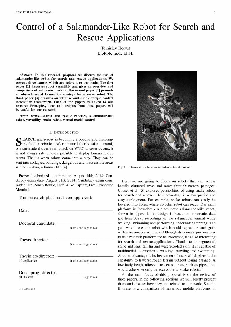
Fig. 1. Pleurobot - a biomimetic salamander-like robot.
Here we are going to focus on robots that can accessheavily cluttered areas and move through narrow passages.Choset et al. [5] explored possibilities of using snake robotsfor search and rescue. Their advantage is a low profile andeasy deployment. For example, snake robots can easily belowered into holes, where no other robot can reach. Our mainplatform is Pleurobot - a biomimetic salamander-like robot,shown in figure 1. Its design is based on kinematic datagot from X-ray recordings of the salamander animal whilewalking, swimming and performing underwater stepping. Thegoal was to create a robot which could reproduce such gaitswith a reasonable accuracy. Although its primary purpose wasto be a research platform for neuroscience, it is also interestingfor search and rescue applications. Thanks to its segmentedspine and legs, tail fin and waterproofed skin, it is capable ofmultimodal locomotion - walking, crawling and swimming.Another advantage is its low center of mass which gives it thecapability to traverse rough terrain without losing balance. Alow body height allows it to access areas, such as pipes, thatwould otherwise only be accessible to snake robots.
As the main focus of this proposal is on the review ofthree papers, in the following sections we will briefly presentthem and discuss how they are related to our work. SectionII presents a comparison of numerous mobile platforms in
EDIC RESEARCH PROPOSAL 2
terms of complexity and versatility. The comparison is doneamong robots with different locomotion modes and differentenvironmental domains. Section III presents an obstacle aidedlocomotion of a snake robot. Section IV presents an intuitiveapproach for achieving locomotion by using virtual springs,dampers and other passive elements that interact with therobot.
II. VERSATILITY AND COMPLEXITY IN MOBILE ROBOTLOCOMOTION
In [1], Nie et al. present a metric to measure versatility ofrobots in multiple environmental domains. The paper discusseshow to define and measure versatility, what makes robotsversatile and how it is related to the complexity of the robot.We believe these are important questions for search and rescuerobotics and will help us with the future improvements ofPleurobot.
A. Versatility
Numerous robots have been attributed as versatile, but aword often had a variety of different meanings. Robots withwhegs (rotary legs) are said to be versatile because they havebetter performance over rough terrain then robots with wheels.Legged robots can use multiple gaits, while tracked robots cancarry a wide range of payloads over different terrains. Eachof them is proclaimed versatile because they excel in theirown domain. The paper addresses versatility as an extensionof mobility that includes operation in and transition amongmultiple domains. Robots can operate in four different envi-
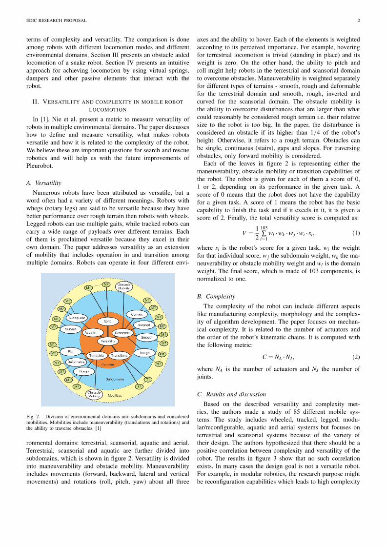
Fig. 2. Division of environmental domains into subdomains and consideredmobilities. Mobilities include maneuverability (translations and rotations) andthe ability to traverse obstacles. [1]
ronmental domains: terrestrial, scansorial, aquatic and aerial.Terrestrial, scansorial and aquatic are further divided intosubdomains, which is shown in figure 2. Versatility is dividedinto maneuverability and obstacle mobility. Maneuverabilityincludes movements (forward, backward, lateral and verticalmovements) and rotations (roll, pitch, yaw) about all three
axes and the ability to hover. Each of the elements is weightedaccording to its perceived importance. For example, hoveringfor terrestrial locomotion is trivial (standing in place) and itsweight is zero. On the other hand, the ability to pitch androll might help robots in the terrestrial and scansorial domainto overcome obstacles. Maneuverability is weighted separatelyfor different types of terrains - smooth, rough and deformablefor the terrestrial domain and smooth, rough, inverted andcurved for the scansorial domain. The obstacle mobility isthe ability to overcome disturbances that are larger than whatcould reasonably be considered rough terrain i.e. their relativesize to the robot is too big. In the paper, the disturbance isconsidered an obstacle if its higher than 1/4 of the robot’sheight. Otherwise, it refers to a rough terrain. Obstacles canbe single, continuous (stairs), gaps and slopes. For traversingobstacles, only forward mobility is considered.
Each of the leaves in figure 2 is representing either themaneuverability, obstacle mobility or transition capabilities ofthe robot. The robot is given for each of them a score of 0,1 or 2, depending on its performance in the given task. Ascore of 0 means that the robot does not have the capabilityfor a given task. A score of 1 means the robot has the basiccapability to finish the task and if it excels in it, it is given ascore of 2. Finally, the total versatility score is computed as:
V =12
103∑
i=1wl ·wk ·w j ·wi · si, (1)
where si is the robot’s score for a given task, wi the weightfor that individual score, w j the subdomain weight, wk the ma-neuverability or obstacle mobility weight and wl is the domainweight. The final score, which is made of 103 components, isnormalized to one.
B. Complexity
The complexity of the robot can include different aspectslike manufacturing complexity, morphology and the complex-ity of algorithm development. The paper focuses on mechan-ical complexity. It is related to the number of actuators andthe order of the robot’s kinematic chains. It is computed withthe following metric:
C = NA ·NJ , (2)
where NA is the number of actuators and NJ the number ofjoints.
C. Results and discussion
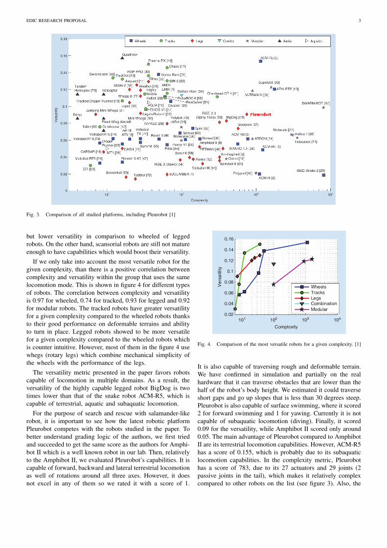
Based on the described versatility and complexity met-rics, the authors made a study of 85 different mobile sys-tems. The study includes wheeled, tracked, legged, modu-lar/reconfigurable, aquatic and aerial systems but focuses onterrestrial and scansorial systems because of the variety oftheir design. The authors hypothesized that there should be apositive correlation between complexity and versatility of therobot. The results in figure 3 show that no such correlationexists. In many cases the design goal is not a versatile robot.For example, in modular robotics, the research purpose mightbe reconfiguration capabilities which leads to high complexity
EDIC RESEARCH PROPOSAL 3
Fig. 3. Comparison of all studied platforms, including Pleurobot [1]
but lower versatility in comparison to wheeled of leggedrobots. On the other hand, scansorial robots are still not matureenough to have capabilities which would boost their versatility.
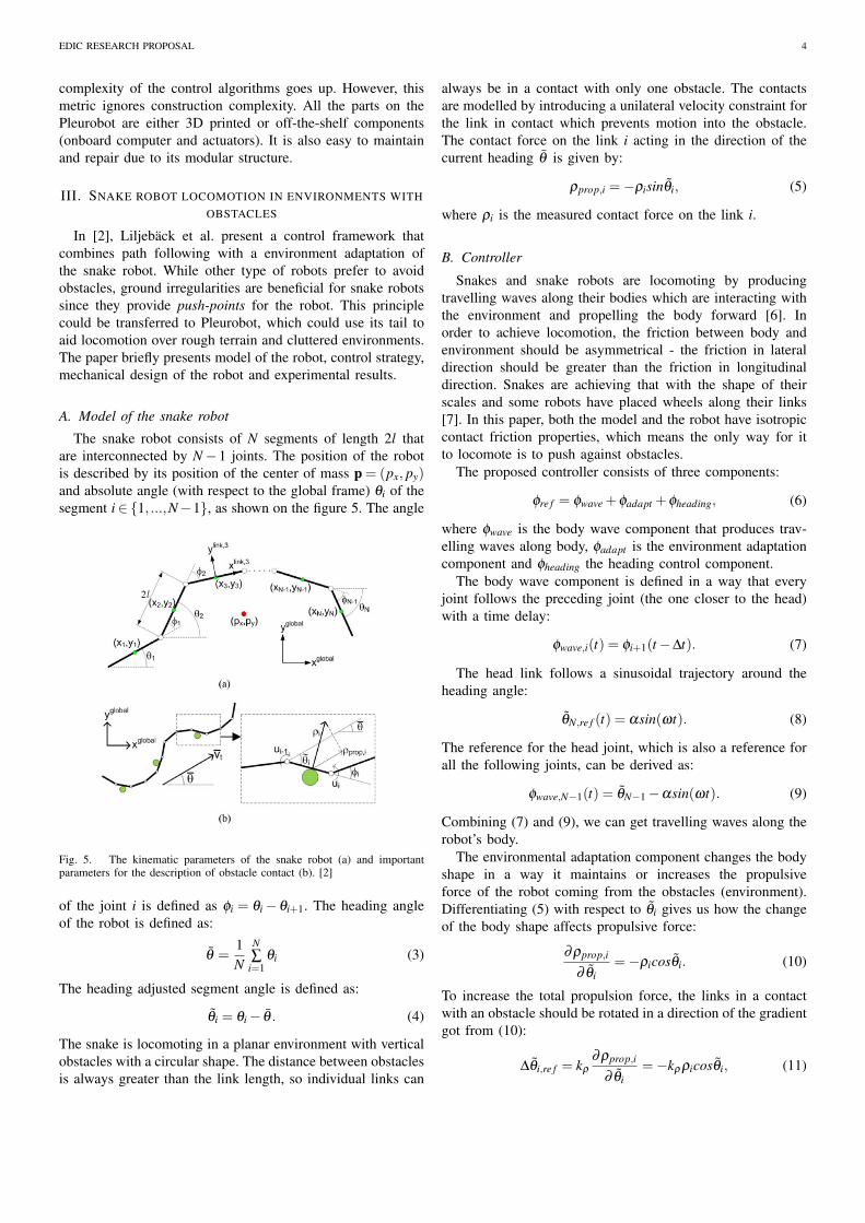
If we only take into account the most versatile robot for thegiven complexity, than there is a positive correlation betweencomplexity and versatility within the group that uses the samelocomotion mode. This is shown in figure 4 for different typesof robots. The correlation between complexity and versatilityis 0.97 for wheeled, 0.74 for tracked, 0.93 for legged and 0.92for modular robots. The tracked robots have greater versatilityfor a given complexity compared to the wheeled robots thanksto their good performance on deformable terrains and abilityto turn in place. Legged robots showed to be more versatilefor a given complexity compared to the wheeled robots whichis counter intuitive. However, most of them in the figure 4 usewhegs (rotary legs) which combine mechanical simplicity ofthe wheels with the performance of the legs.
The versatility metric presented in the paper favors robotscapable of locomotion in multiple domains. As a result, theversatility of the highly capable legged robot BigDog is twotimes lower than that of the snake robot ACM-R5, which iscapable of terrestrial, aquatic and subaquatic locomotion.
For the purpose of search and rescue with salamander-likerobot, it is important to see how the latest robotic platformPleurobot competes with the robots studied in the paper. Tobetter understand grading logic of the authors, we first triedand succeeded to get the same score as the authors for Amphi-bot II which is a well known robot in our lab. Then, relativelyto the Amphibot II, we evaluated Pleurobot’s capabilities. It iscapable of forward, backward and lateral terrestrial locomotionas well of rotations around all three axes. However, it doesnot excel in any of them so we rated it with a score of 1.
Fig. 4. Comparison of the most versatile robots for a given complexity. [1]
It is also capable of traversing rough and deformable terrain.We have confirmed in simulation and partially on the realhardware that it can traverse obstacles that are lower than thehalf of the robot’s body height. We estimated it could traverseshort gaps and go up slopes that is less than 30 degrees steep.Pleurobot is also capable of surface swimming, where it scored2 for forward swimming and 1 for yawing. Currently it is notcapable of subaquatic locomotion (diving). Finally, it scored0.09 for the versatility, while Amphibot II scored only around0.05. The main advantage of Pleurobot compared to AmphibotII are its terrestrial locomotion capabilities. However, ACM-R5has a score of 0.155, which is probably due to its subaquaticlocomotion capabilities. In the complexity metric, Pleurobothas a score of 783, due to its 27 actuators and 29 joints (2passive joints in the tail), which makes it relatively complexcompared to other robots on the list (see figure 3). Also, the
EDIC RESEARCH PROPOSAL 4
complexity of the control algorithms goes up. However, thismetric ignores construction complexity. All the parts on thePleurobot are either 3D printed or off-the-shelf components(onboard computer and actuators). It is also easy to maintainand repair due to its modular structure.
III. SNAKE ROBOT LOCOMOTION IN ENVIRONMENTS WITHOBSTACLES
In [2], Liljeback et al. present a control framework thatcombines path following with a environment adaptation ofthe snake robot. While other type of robots prefer to avoidobstacles, ground irregularities are beneficial for snake robotssince they provide push-points for the robot. This principlecould be transferred to Pleurobot, which could use its tail toaid locomotion over rough terrain and cluttered environments.The paper briefly presents model of the robot, control strategy,mechanical design of the robot and experimental results.
A. Model of the snake robot
The snake robot consists of N segments of length 2l thatare interconnected by N−1 joints. The position of the robotis described by its position of the center of mass p = (px, py)and absolute angle (with respect to the global frame) θi of thesegment i∈ {1, ...,N−1}, as shown on the figure 5. The angle
Fig. 5. The kinematic parameters of the snake robot (a) and importantparameters for the description of obstacle contact (b). [2]
of the joint i is defined as φi = θi−θi+1. The heading angleof the robot is defined as:
θ =1N
N∑
i=1θi (3)
The heading adjusted segment angle is defined as:
θi = θi− θ . (4)
The snake is locomoting in a planar environment with verticalobstacles with a circular shape. The distance between obstaclesis always greater than the link length, so individual links can
always be in a contact with only one obstacle. The contactsare modelled by introducing a unilateral velocity constraint forthe link in contact which prevents motion into the obstacle.The contact force on the link i acting in the direction of thecurrent heading θ is given by:
ρprop,i =−ρisinθi, (5)
where ρi is the measured contact force on the link i.
B. Controller
Snakes and snake robots are locomoting by producingtravelling waves along their bodies which are interacting withthe environment and propelling the body forward [6]. Inorder to achieve locomotion, the friction between body andenvironment should be asymmetrical - the friction in lateraldirection should be greater than the friction in longitudinaldirection. Snakes are achieving that with the shape of theirscales and some robots have placed wheels along their links[7]. In this paper, both the model and the robot have isotropiccontact friction properties, which means the only way for itto locomote is to push against obstacles.
The proposed controller consists of three components:
φre f = φwave +φadapt +φheading, (6)
where φwave is the body wave component that produces trav-elling waves along body, φadapt is the environment adaptationcomponent and φheading the heading control component.
The body wave component is defined in a way that everyjoint follows the preceding joint (the one closer to the head)with a time delay:
φwave,i(t) = φi+1(t−∆t). (7)
The head link follows a sinusoidal trajectory around theheading angle:
θN,re f (t) = αsin(ωt). (8)
The reference for the head joint, which is also a reference forall the following joints, can be derived as:
φwave,N−1(t) = θN−1−αsin(ωt). (9)
Combining (7) and (9), we can get travelling waves along therobot’s body.
The environmental adaptation component changes the bodyshape in a way it maintains or increases the propulsiveforce of the robot coming from the obstacles (environment).Differentiating (5) with respect to θi gives us how the changeof the body shape affects propulsive force:
∂ρprop,i
∂ θi=−ρicosθi. (10)
To increase the total propulsion force, the links in a contactwith an obstacle should be rotated in a direction of the gradientgot from (10):
∆θi,re f = kρ
∂ρprop,i
∂ θi=−kρ ρicosθi, (11)
EDIC RESEARCH PROPOSAL 5
where kρ is a controller gain. The adaptation affects onlythe link in the contact, while the orientation of neighboringlinks stays unchanged: ∆θi−1,re f = ∆θi+1,re f = 0. Since thejoint angle is defined as φi = θi− θi+1, we can derive howthe contact on the link i affects the joint angles φi−1 and φi:
∆φi−1,re f = ∆θi−1,re f −∆θi,re f = kρ ρicosθi,
∆φi,re f = ∆θi,re f −∆θi+1,re f =−kρ ρicosθi.(12)
Finally we can derive the adaptation of the single joint angle:
φadapt,i =−kρ(ρicosθi−ρi+1cosθi+1). (13)
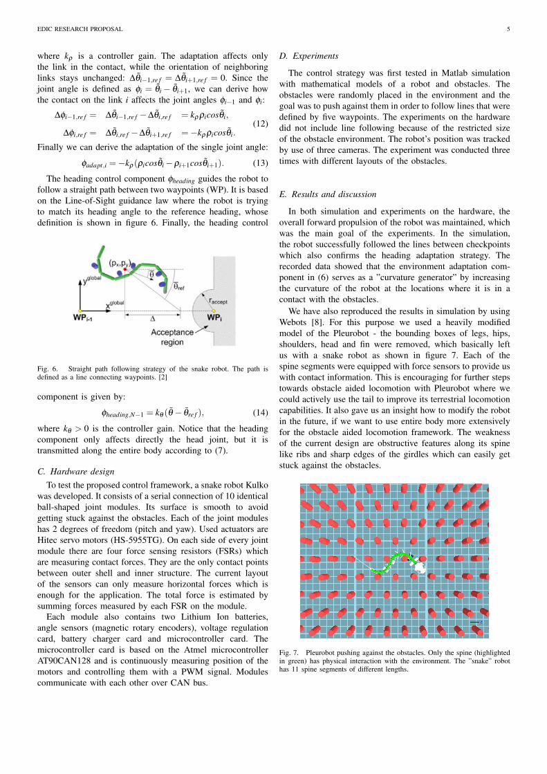
The heading control component φheading guides the robot tofollow a straight path between two waypoints (WP). It is basedon the Line-of-Sight guidance law where the robot is tryingto match its heading angle to the reference heading, whosedefinition is shown in figure 6. Finally, the heading control
Fig. 6. Straight path following strategy of the snake robot. The path isdefined as a line connecting waypoints. [2]
component is given by:
φheading,N−1 = kθ (θ − θre f ), (14)
where kθ > 0 is the controller gain. Notice that the headingcomponent only affects directly the head joint, but it istransmitted along the entire body according to (7).
C. Hardware designTo test the proposed control framework, a snake robot Kulko
was developed. It consists of a serial connection of 10 identicalball-shaped joint modules. Its surface is smooth to avoidgetting stuck against the obstacles. Each of the joint moduleshas 2 degrees of freedom (pitch and yaw). Used actuators areHitec servo motors (HS-5955TG). On each side of every jointmodule there are four force sensing resistors (FSRs) whichare measuring contact forces. They are the only contact pointsbetween outer shell and inner structure. The current layoutof the sensors can only measure horizontal forces which isenough for the application. The total force is estimated bysumming forces measured by each FSR on the module.
Each module also contains two Lithium Ion batteries,angle sensors (magnetic rotary encoders), voltage regulationcard, battery charger card and microcontroller card. Themicrocontroller card is based on the Atmel microcontrollerAT90CAN128 and is continuously measuring position of themotors and controlling them with a PWM signal. Modulescommunicate with each other over CAN bus.
D. Experiments
The control strategy was first tested in Matlab simulationwith mathematical models of a robot and obstacles. Theobstacles were randomly placed in the environment and thegoal was to push against them in order to follow lines that weredefined by five waypoints. The experiments on the hardwaredid not include line following because of the restricted sizeof the obstacle environment. The robot’s position was trackedby use of three cameras. The experiment was conducted threetimes with different layouts of the obstacles.
E. Results and discussion
In both simulation and experiments on the hardware, theoverall forward propulsion of the robot was maintained, whichwas the main goal of the experiments. In the simulation,the robot successfully followed the lines between checkpointswhich also confirms the heading adaptation strategy. Therecorded data showed that the environment adaptation com-ponent in (6) serves as a ”curvature generator” by increasingthe curvature of the robot at the locations where it is in acontact with the obstacles.
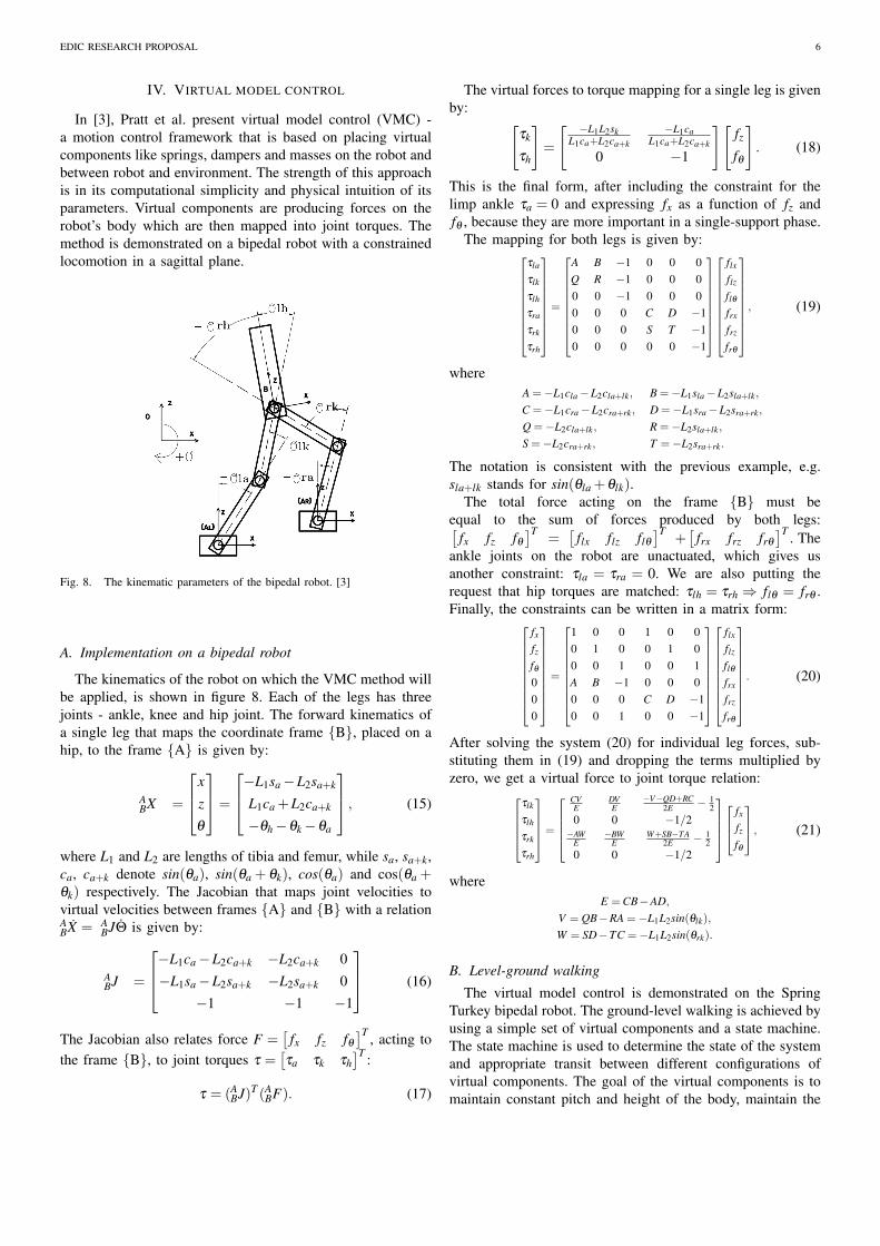
We have also reproduced the results in simulation by usingWebots [8]. For this purpose we used a heavily modifiedmodel of the Pleurobot - the bounding boxes of legs, hips,shoulders, head and fin were removed, which basically leftus with a snake robot as shown in figure 7. Each of thespine segments were equipped with force sensors to provide uswith contact information. This is encouraging for further stepstowards obstacle aided locomotion with Pleurobot where wecould actively use the tail to improve its terrestrial locomotioncapabilities. It also gave us an insight how to modify the robotin the future, if we want to use entire body more extensivelyfor the obstacle aided locomotion framework. The weaknessof the current design are obstructive features along its spinelike ribs and sharp edges of the girdles which can easily getstuck against the obstacles.
Fig. 7. Pleurobot pushing against the obstacles. Only the spine (highlightedin green) has physical interaction with the environment. The ”snake” robothas 11 spine segments of different lengths.
EDIC RESEARCH PROPOSAL 6
IV. VIRTUAL MODEL CONTROL
In [3], Pratt et al. present virtual model control (VMC) -a motion control framework that is based on placing virtualcomponents like springs, dampers and masses on the robot andbetween robot and environment. The strength of this approachis in its computational simplicity and physical intuition of itsparameters. Virtual components are producing forces on therobot’s body which are then mapped into joint torques. Themethod is demonstrated on a bipedal robot with a constrainedlocomotion in a sagittal plane.
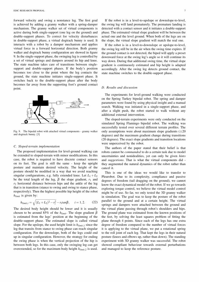
Fig. 8. The kinematic parameters of the bipedal robot. [3]
A. Implementation on a bipedal robot
The kinematics of the robot on which the VMC method willbe applied, is shown in figure 8. Each of the legs has threejoints - ankle, knee and hip joint. The forward kinematics ofa single leg that maps the coordinate frame {B}, placed on ahip, to the frame {A} is given by:
ABX =
x
z
θ
=
−L1sa−L2sa+k
L1ca +L2ca+k
−θh−θk−θa
, (15)
where L1 and L2 are lengths of tibia and femur, while sa, sa+k,ca, ca+k denote sin(θa), sin(θa + θk), cos(θa) and cos(θa +θk) respectively. The Jacobian that maps joint velocities tovirtual velocities between frames {A} and {B} with a relationABX = A
BJΘ is given by:
ABJ =
−L1ca−L2ca+k −L2ca+k 0−L1sa−L2sa+k −L2sa+k 0
−1 −1 −1
(16)
The Jacobian also relates force F =[
fx fz fθ
]T , acting tothe frame {B}, to joint torques τ =
[τa τk τh
]T :
τ = (ABJ)T (A
BF). (17)
The virtual forces to torque mapping for a single leg is givenby: [
τk
τh
]=
[ −L1L2skL1ca+L2ca+k
−L1caL1ca+L2ca+k
0 −1
][fz
fθ
]. (18)
This is the final form, after including the constraint for thelimp ankle τa = 0 and expressing fx as a function of fz andfθ , because they are more important in a single-support phase.
The mapping for both legs is given by:
τla
τlk
τlh
τra
τrk
τrh
=
A B −1 0 0 0Q R −1 0 0 00 0 −1 0 0 00 0 0 C D −10 0 0 S T −10 0 0 0 0 −1
flx
flz
flθ
frx
frz
frθ
, (19)
whereA =−L1cla−L2cla+lk, B =−L1sla−L2sla+lk,
C =−L1cra−L2cra+rk, D =−L1sra−L2sra+rk,
Q =−L2cla+lk, R =−L2sla+lk,
S =−L2cra+rk, T =−L2sra+rk.
The notation is consistent with the previous example, e.g.sla+lk stands for sin(θla +θlk).
The total force acting on the frame {B} must beequal to the sum of forces produced by both legs:[
fx fz fθ
]T=[
flx flz flθ]T
+[
frx frz frθ
]T . Theankle joints on the robot are unactuated, which gives usanother constraint: τla = τra = 0. We are also putting therequest that hip torques are matched: τlh = τrh ⇒ flθ = frθ .Finally, the constraints can be written in a matrix form:
fx
fz
fθ
000
=
1 0 0 1 0 00 1 0 0 1 00 0 1 0 0 1A B −1 0 0 00 0 0 C D −10 0 1 0 0 −1
flx
flz
flθ
frx
frz
frθ
. (20)
After solving the system (20) for individual leg forces, sub-stituting them in (19) and dropping the terms multiplied byzero, we get a virtual force to joint torque relation:
τlk
τlh
τrk
τrh
=
CVE
DVE
−V−QD+RC2E − 1
20 0 −1/2−AW
E−BW
EW+SB−TA
2E − 12
0 0 −1/2
fx
fz
fθ
, (21)
whereE =CB−AD,
V = QB−RA =−L1L2sin(θlk),
W = SD−TC =−L1L2sin(θrk).
B. Level-ground walking
The virtual model control is demonstrated on the SpringTurkey bipedal robot. The ground-level walking is achieved byusing a simple set of virtual components and a state machine.The state machine is used to determine the state of the systemand appropriate transit between different configurations ofvirtual components. The goal of the virtual components is tomaintain constant pitch and height of the body, maintain the
EDIC RESEARCH PROPOSAL 7
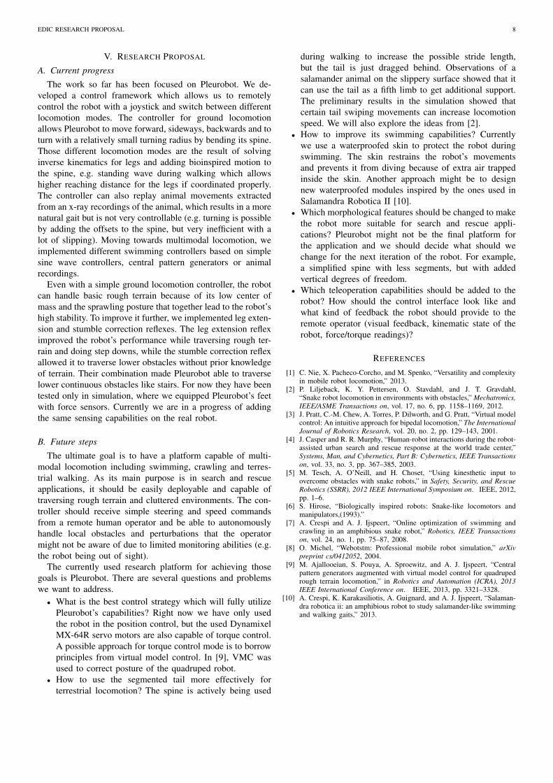
forward velocity and swing a nonstance leg. The first goalis achieved by adding a granny walker with a spring-dampermechanism. The granny walker set of virtual components isactive during both single-support (one leg on the ground) anddouble-support phases. To correct for velocity disturbancesin double-support phase, a virtual dogtrack bunny is used. Itinteracts with a robot by a damper mechanism and appliesvirtual force in a forward horizontal direction. Both grannywalker and dogtrack bunny configuration are showed in figure9. In the single-support phase, the swinging leg is controlled bya set of virtual springs and dampers around its hip and knee.The state machine takes care of transitions between single-support and double-support phases. If the body’s positionbecomes too close to the point where the leg contacts theground, the state machine initiates single-support phase. Itswitches back to the double-support phase after the bodybecomes far away from the supporting foot’s ground contactpoint.
Fig. 9. The bipedal robot with attached virtual components - granny walkerand dogtrack bunny. [3]
C. Sloped-terrain implementation
The proposed implementation for level-ground walking canbe extended to sloped-terrain with minor modifications. In thiscase, the robot is required to have discrete contact sensorson its feet. The goal is still the same - keep the uprightposture and maintain desired velocity. The height of theposture should be modified in a way that we avoid reachingsingular configurations, e.g. fully extended knee. Let L1 +L2be the total length of the leg, β the slope gradient, r1 andr2 horizontal distance between hips and the ankle of the legthat is in transition (stance to swing and swing to stance phase,respectively). Then the highest possible hip height of the robothlimit is given by:
hlimit,i =√(L1 +L2)2− r2
i − ritanβ , i = 1,2. (22)
The desired body height should be lower and it is usuallychosen to be around 85% of the hlimit . The slope gradient β
is estimated from the legs’ position at the beginning of thedouble-support phase. The estimated slope is called virtualslope. For the upslope, the used height limit is hlimit,1 since theleg that transits from stance to swing phase can reach singularconfiguration. For the downslope, both of the legs could endup in singular configuration. However, the strategy for endingthe swing phase is when the vertical projection of the hip isbetween both legs. In this case, only the swinging leg can getoverextended, so for the maximum body height hlimit,2 is used.
If the robot is in a level-to-upslope or downslope-to-level,the swing leg will land prematurely. The premature landing isdetected with a contact sensor and it initiates a double-supportphase. The estimated virtual slope gradient will be between theactual one and the level ground. When both of the legs are onthe slope, the virtual slope gradient will match the real one.
If the robot is in a level-to-downslope or upslope-to-level,the swing leg still be in the air when the swing time expires. Ifthe ground contact is not detected, the biped will apply a presetdownward force at the swing leg’s angle so it will continue itsway down. During that additional swing time, the virtual slopegradient is continuously estimated and hip height is adaptedaccordingly. After the swing leg detects ground contact, thestate machine switches to the double-support phase.
D. Results and discussion
The experiments for level-ground walking were conductedon the Spring Turkey bipedal robot. The spring and damperparameters were found by using physical insight and a manualsearch. Walking was initiated in a single-support phase, andafter a slight push, the robot started to walk without anyadditional external intervention.
The sloped-terrain experiments were only conducted on thesimulated Spring Flamingo bipedal robot. The walking wassuccessfully tested over several different terrain profiles. Theonly assumptions were about maximum slope gradients (±20degrees) and the maximum gradient change during transitions(20 degrees). The exact slope gradients and transition locationswere unperceived by the robot.
The authors of the paper stated that their belief is thatrobots cannot be commanded to do a certain task due to modeluncertainties and nonidealities, yet can only be given hintsand suggestions. That is what the virtual components did -they augmented the natural dynamics of the robot rather thancancel it.
This is one of the ideas we would like to transfer toPleurobot. Due to its complexity, compliance and passivedegrees of freedom (tail dragging on the ground), we cannotknow the exact dynamical model of the robot. If we go towardsexploring torque control, we believe the virtual model controlmight be of use. So far, we only tested the 3D granny walkerin simulation. The goal was to keep the posture of the robotparallel to the ground and at a certain height. The virtualsprings and dampers were attached between the ground andthe virtual plane passing through robot’s shoulders and hips.The ground plane was estimated from the known positions ofthe feet, by solving the least squares problem of fitting theplane through 4 points. Since each of the legs has one extradegree of freedom compared to the number of virtual forcesit is applying to the virtual plane, we put a rotational springto the roll joint of each leg. That kept the legs in their naturalposture (knees and elbows up, rather than down). The standingexperiment with 3D granny walker was successful. The robotshowed compliant behaviour towards external perturbationsand managed to keep the reference posture.
EDIC RESEARCH PROPOSAL 8
V. RESEARCH PROPOSAL
A. Current progress
The work so far has been focused on Pleurobot. We de-veloped a control framework which allows us to remotelycontrol the robot with a joystick and switch between differentlocomotion modes. The controller for ground locomotionallows Pleurobot to move forward, sideways, backwards and toturn with a relatively small turning radius by bending its spine.Those different locomotion modes are the result of solvinginverse kinematics for legs and adding bioinspired motion tothe spine, e.g. standing wave during walking which allowshigher reaching distance for the legs if coordinated properly.The controller can also replay animal movements extractedfrom an x-ray recordings of the animal, which results in a morenatural gait but is not very controllable (e.g. turning is possibleby adding the offsets to the spine, but very inefficient with alot of slipping). Moving towards multimodal locomotion, weimplemented different swimming controllers based on simplesine wave controllers, central pattern generators or animalrecordings.
Even with a simple ground locomotion controller, the robotcan handle basic rough terrain because of its low center ofmass and the sprawling posture that together lead to the robot’shigh stability. To improve it further, we implemented leg exten-sion and stumble correction reflexes. The leg extension refleximproved the robot’s performance while traversing rough ter-rain and doing step downs, while the stumble correction reflexallowed it to traverse lower obstacles without prior knowledgeof terrain. Their combination made Pleurobot able to traverselower continuous obstacles like stairs. For now they have beentested only in simulation, where we equipped Pleurobot’s feetwith force sensors. Currently we are in a progress of addingthe same sensing capabilities on the real robot.
B. Future steps
The ultimate goal is to have a platform capable of multi-modal locomotion including swimming, crawling and terres-trial walking. As its main purpose is in search and rescueapplications, it should be easily deployable and capable oftraversing rough terrain and cluttered environments. The con-troller should receive simple steering and speed commandsfrom a remote human operator and be able to autonomouslyhandle local obstacles and perturbations that the operatormight not be aware of due to limited monitoring abilities (e.g.the robot being out of sight).
The currently used research platform for achieving thosegoals is Pleurobot. There are several questions and problemswe want to address.• What is the best control strategy which will fully utilize
Pleurobot’s capabilities? Right now we have only usedthe robot in the position control, but the used DynamixelMX-64R servo motors are also capable of torque control.A possible approach for torque control mode is to borrowprinciples from virtual model control. In [9], VMC wasused to correct posture of the quadruped robot.
• How to use the segmented tail more effectively forterrestrial locomotion? The spine is actively being used
during walking to increase the possible stride length,but the tail is just dragged behind. Observations of asalamander animal on the slippery surface showed that itcan use the tail as a fifth limb to get additional support.The preliminary results in the simulation showed thatcertain tail swiping movements can increase locomotionspeed. We will also explore the ideas from [2].
• How to improve its swimming capabilities? Currentlywe use a waterproofed skin to protect the robot duringswimming. The skin restrains the robot’s movementsand prevents it from diving because of extra air trappedinside the skin. Another approach might be to designnew waterproofed modules inspired by the ones used inSalamandra Robotica II [10].
• Which morphological features should be changed to makethe robot more suitable for search and rescue appli-cations? Pleurobot might not be the final platform forthe application and we should decide what should wechange for the next iteration of the robot. For example,a simplified spine with less segments, but with addedvertical degrees of freedom.
• Which teleoperation capabilities should be added to therobot? How should the control interface look like andwhat kind of feedback the robot should provide to theremote operator (visual feedback, kinematic state of therobot, force/torque readings)?
REFERENCES
[1] C. Nie, X. Pacheco-Corcho, and M. Spenko, “Versatility and complexityin mobile robot locomotion,” 2013.
[2] P. Liljeback, K. Y. Pettersen, O. Stavdahl, and J. T. Gravdahl,“Snake robot locomotion in environments with obstacles,” Mechatronics,IEEE/ASME Transactions on, vol. 17, no. 6, pp. 1158–1169, 2012.
[3] J. Pratt, C.-M. Chew, A. Torres, P. Dilworth, and G. Pratt, “Virtual modelcontrol: An intuitive approach for bipedal locomotion,” The InternationalJournal of Robotics Research, vol. 20, no. 2, pp. 129–143, 2001.
[4] J. Casper and R. R. Murphy, “Human-robot interactions during the robot-assisted urban search and rescue response at the world trade center,”Systems, Man, and Cybernetics, Part B: Cybernetics, IEEE Transactionson, vol. 33, no. 3, pp. 367–385, 2003.
[5] M. Tesch, A. O’Neill, and H. Choset, “Using kinesthetic input toovercome obstacles with snake robots,” in Safety, Security, and RescueRobotics (SSRR), 2012 IEEE International Symposium on. IEEE, 2012,pp. 1–6.
[6] S. Hirose, “Biologically inspired robots: Snake-like locomotors andmanipulators,(1993).”
[7] A. Crespi and A. J. Ijspeert, “Online optimization of swimming andcrawling in an amphibious snake robot,” Robotics, IEEE Transactionson, vol. 24, no. 1, pp. 75–87, 2008.
[8] O. Michel, “Webotstm: Professional mobile robot simulation,” arXivpreprint cs/0412052, 2004.
[9] M. Ajallooeian, S. Pouya, A. Sproewitz, and A. J. Ijspeert, “Centralpattern generators augmented with virtual model control for quadrupedrough terrain locomotion,” in Robotics and Automation (ICRA), 2013IEEE International Conference on. IEEE, 2013, pp. 3321–3328.
[10] A. Crespi, K. Karakasiliotis, A. Guignard, and A. J. Ijspeert, “Salaman-dra robotica ii: an amphibious robot to study salamander-like swimmingand walking gaits,” 2013.