Embed Size (px)
Citation preview
MIL
LEN
NIU
M S
TEEL
200
8
192
Eddy current inspection in hot rolling millsEddy current testing is a common method for the surface inspection of semi-finished products. The general trend today is to perform eddy current testing on hot material during production, where it is able, to provide prompt feedback on process stability and product quality. It can identify a large variety of defects, including scabs, laps, pinholes and inclusions, as well as repetitive defects caused by defective rolls and rollers. This paper describes a fully automated hot testing system and presents practical experience with eddy current surface inspection on hot steel rod.
Increasing production speeds and customer demands for higher quality products have led to the development
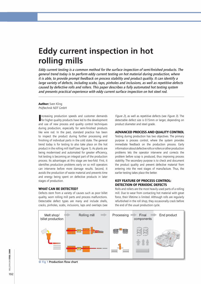
and use of new process and quality control techniques during production, especially for semi-finished products like wire rod. In the past, standard practice has been to inspect the product during further processing and finishing of individual parts in the cold state. The general trend today is for testing to also take place on the hot product in the rolling mill itself (see Figure 1). As plants are being modernised and automated for greater efficiency, hot testing is becoming an integral part of the production process. Its advantages at this stage are two-fold. First, it identifies production problems early on so mill operators can intervene before more damage results. Second, it avoids the production of waste material and prevents time and energy being spent on defective products in later stages of production.
WHAT CAN BE DETECTED?Defects stem from a variety of causes such as poor billet quality, worn rolling mill parts and process malfunctions. Detectable defect types are many and include shells, cracks, pinholes, scabs, inclusions, laps and overlaps (see
Author: Sven KlingPrüftechnik NDT GmbH
Figure 2), as well as repetitive defects (see Figure 3). The detectable defect size is 0.15mm or larger, depending on product diameter and steel grade.
ADVANCED PROCESS AND QUALITY CONTROLTesting during production has two objectives. The primary purpose is process control, where the system provides immediate feedback on the production process. Early information about defective rolls or rollers or other production problems lets the operator intervene and corrects the problem before scrap is produced, thus improving process stability. The secondary purpose is to check and document the product quality and prevent defective material from entering into the next stages of manufacture. Thus, the earlier testing takes place the better.
KEY FEATURE OF PROCESS CONTROL: DETECTION OF PERIODIC DEFECTSRolls and rollers are the most heavily used parts of a rolling mill. Due to wear from contacting hot material with great force, their lifetime is limited. Although rolls are regularly refurbished in the roll shop, they occasionally crack before the end of the usual production cycle.
r Fig 1 Production flow chart
FORMING PROcesses
MIL
LEN
NIU
M S
TEEL
200
8
193
a
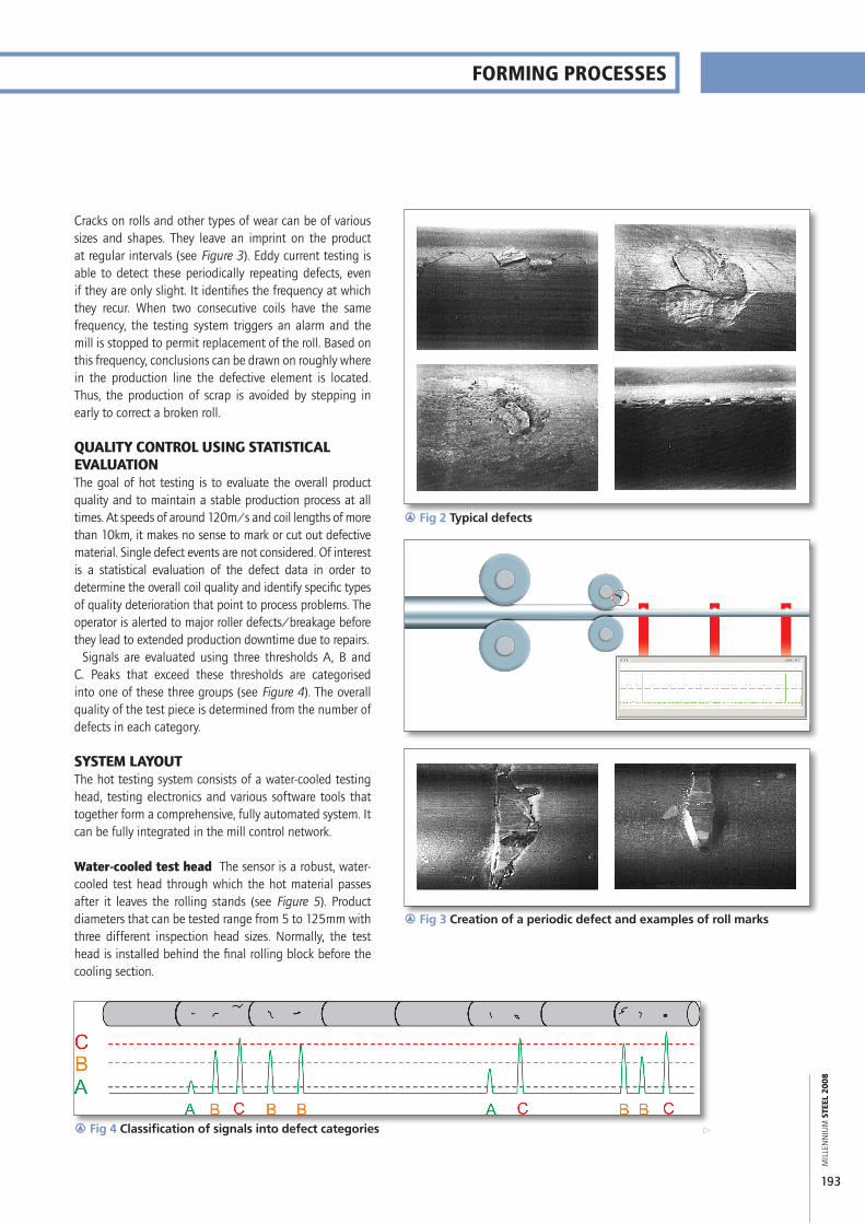
Cracks on rolls and other types of wear can be of various sizes and shapes. They leave an imprint on the product at regular intervals (see Figure 3). Eddy current testing is able to detect these periodically repeating defects, even if they are only slight. It identifies the frequency at which they recur. When two consecutive coils have the same frequency, the testing system triggers an alarm and the mill is stopped to permit replacement of the roll. Based on this frequency, conclusions can be drawn on roughly where in the production line the defective element is located. Thus, the production of scrap is avoided by stepping in early to correct a broken roll.
QUALITY CONTROL USING STATISTICAL EVALUATIONThe goal of hot testing is to evaluate the overall product quality and to maintain a stable production process at all times. At speeds of around 120m/s and coil lengths of more than 10km, it makes no sense to mark or cut out defective material. Single defect events are not considered. Of interest is a statistical evaluation of the defect data in order to determine the overall coil quality and identify specific types of quality deterioration that point to process problems. The operator is alerted to major roller defects/breakage before they lead to extended production downtime due to repairs.
Signals are evaluated using three thresholds A, B and C. Peaks that exceed these thresholds are categorised into one of these three groups (see Figure 4). The overall quality of the test piece is determined from the number of defects in each category.
SYSTEM LAYOUTThe hot testing system consists of a water-cooled testing head, testing electronics and various software tools that together form a comprehensive, fully automated system. It can be fully integrated in the mill control network.
Water-cooled test head The sensor is a robust, water-cooled test head through which the hot material passes after it leaves the rolling stands (see Figure 5). Product diameters that can be tested range from 5 to 125mm with three different inspection head sizes. Normally, the test head is installed behind the final rolling block before the cooling section.
r Fig 3 Creation of a periodic defect and examples of roll marks
r Fig 2 Typical defects
r Fig 4 Classification of signals into defect categories
MIL
LEN
NIU
M S
TEEL
200
8
194
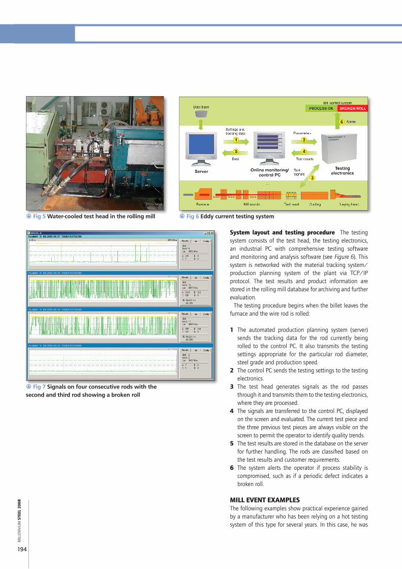
System layout and testing procedure The testing system consists of the test head, the testing electronics, an industrial PC with comprehensive testing software and monitoring and analysis software (see Figure 6). This system is networked with the material tracking system/production planning system of the plant via TCP/IP protocol. The test results and product information are stored in the rolling mill database for archiving and further evaluation.
The testing procedure begins when the billet leaves the furnace and the wire rod is rolled:
1 The automated production planning system (server) sends the tracking data for the rod currently being rolled to the control PC. It also transmits the testing settings appropriate for the particular rod diameter, steel grade and production speed.
2 The control PC sends the testing settings to the testing electronics.
3 The test head generates signals as the rod passes through it and transmits them to the testing electronics, where they are processed.
4 The signals are transferred to the control PC, displayed on the screen and evaluated. The current test piece and the three previous test pieces are always visible on the screen to permit the operator to identify quality trends.
5 The test results are stored in the database on the server for further handling. The rods are classified based on the test results and customer requirements.
6 The system alerts the operator if process stability is compromised, such as if a periodic defect indicates a broken roll.
MILL EVENT EXAMPLESThe following examples show practical experience gained by a manufacturer who has been relying on a hot testing system of this type for several years. In this case, he was
r Fig 7 Signals on four consecutive rods with the second and third rod showing a broken roll
r Fig 5 Water-cooled test head in the rolling mill r Fig 6 Eddy current testing system
FORMING PROcesses
MIL
LEN
NIU
M S
TEEL
200
8
195
evaluating the latest advancements in the eddy current testing system and evaluation technologies.
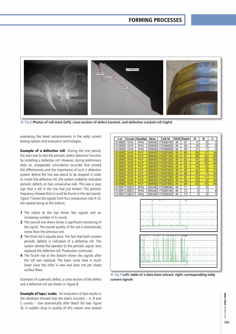
Example of a defective roll During the trial period, the plan was to test the periodic defect detection function by installing a defective roll. However, during preliminary tests an unexpected coincidence occurred that proved the effectiveness and the importance of such a detection system. Before the line was about to be stopped in order to install the defective roll, the system suddenly indicated periodic defects on two consecutive rods. This was a clear sign that a roll in the line had just broken. The periodic frequency showed that it could be found in the last stands. Figure 7 shows the signals from four consecutive rods A–D, the newest being at the bottom.
1 The oldest at the top shows few signals and an increasing number of A counts.
2 The second one down shows a significant worsening of the signal. The overall quality of the rod is dramatically worse than the previous one.
3 The third rod is equally poor. The fact that both contain periodic defects is indicative of a defective roll. The system alerted the operator to the periodic signal, who replaced the defective roll. Production continued.
4 The fourth rod at the bottom shows the signals after the roll was replaced. The basic noise level is much lower since the roller is new and does not yet create surface flaws.
Examples of a periodic defect, a cross-section of the defect and a defective roll are shown in Figure 8.
Example of laps/scabs An evaluation of test results in the database showed that the alarm counters – A, B and C counts – rose dramatically after Batch 60 (see Figure 9). A sudden drop in quality of this nature over several
r Fig 8 Photos of roll mark (left), cross-section of defect (centre), and defective cracked roll (right)
r Fig 9 Left: table of a data base extract; right: corresponding eddy current signals
a
MIL
LEN
NIU
M S
TEEL
200
8
196
FORMING PROcesses
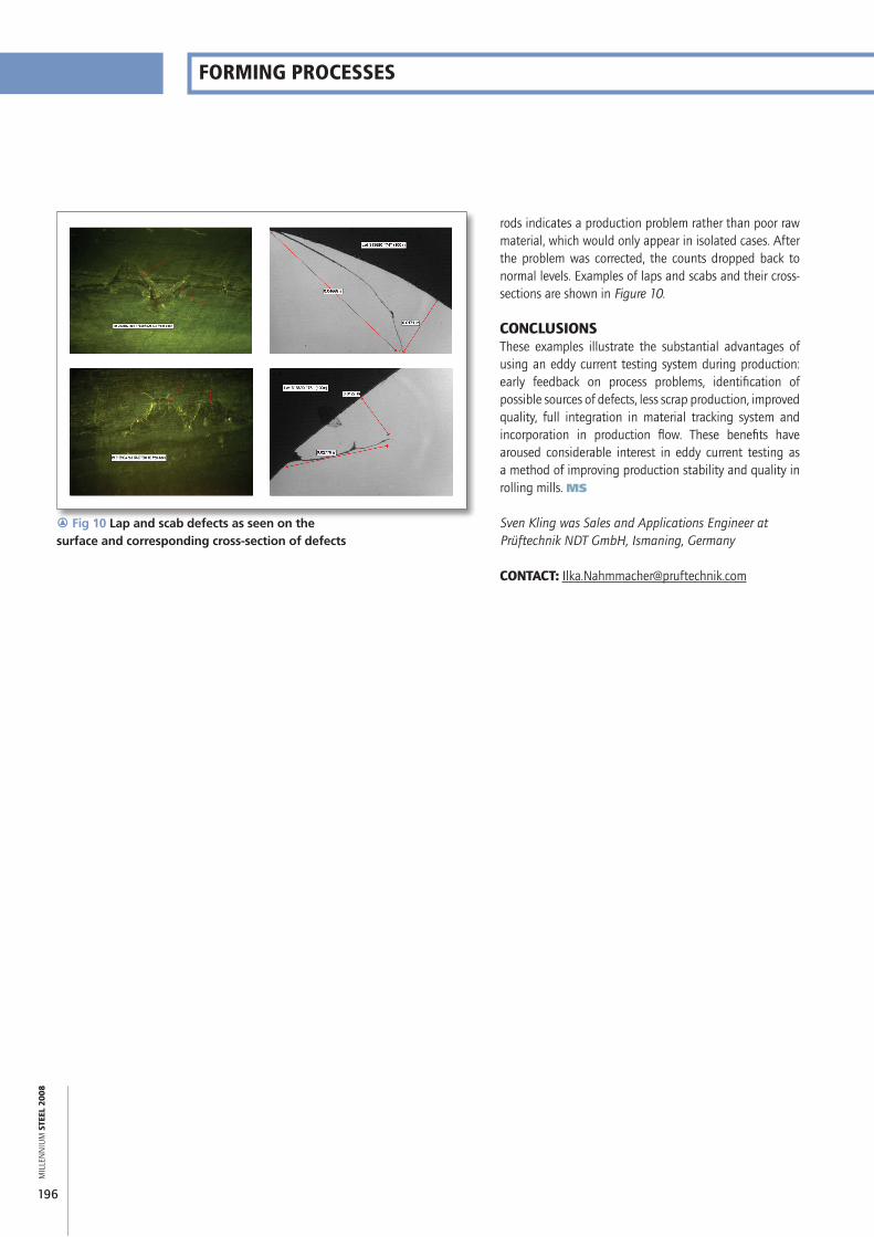
r Fig 10 Lap and scab defects as seen on the surface and corresponding cross-section of defects
rods indicates a production problem rather than poor raw material, which would only appear in isolated cases. After the problem was corrected, the counts dropped back to normal levels. Examples of laps and scabs and their cross- sections are shown in Figure 10.
CONCLUSIONSThese examples illustrate the substantial advantages of using an eddy current testing system during production: early feedback on process problems, identification of possible sources of defects, less scrap production, improved quality, full integration in material tracking system and incorporation in production flow. These benefits have aroused considerable interest in eddy current testing as a method of improving production stability and quality in rolling mills. MS
Sven Kling was Sales and Applications Engineer at Prüftechnik NDT GmbH, Ismaning, Germany
CONTACT: [email protected]


![[Webinar Slides] Advanced Eddy Current Weld Inspection 660 KB](https://img.pdfslide.us/doc/110x75/5849ae091a28aba93a927108/webinar-slides-advanced-eddy-current-weld-inspection-660-kb.jpg)