Embed Size (px)
Citation preview
Pulsed Eddy Current Testing (PECT) Inspection Technique
Innospection Limited Unit 1, Howemoss Avenue, Kirkhill Industrial Estate, Dyce, AB21 0GP, Aberdeen, United Kingdom
Tel : +44 (0)1224-724744 Fax : +44 (0)1224-774087 Web : www.innospection.com Email : [email protected]
© Copyright Innospection Ltd 2017. All rights reserved.
Introduction Pulsed Eddy Current Testing (PECT) is an inspection technique used for corrosion under insulation (CUI) screening on carbon steel structures as pipes, vessels, tanks and spherical tank legs without the need of contact with the steel surface. PECT is a static technique able to measure spot percentage variations in steel thickness through any non-conductive and non-magnetic material between the sensor and steel surface such as air, insulation material, concrete, plastics, coatings, paint, sea water, marine growth, deposits, oil, etc. PECT is a comparative technique where the percentage variations measured on the specimen are compared with a calibration value which is always assumed to be the full wall thickness.
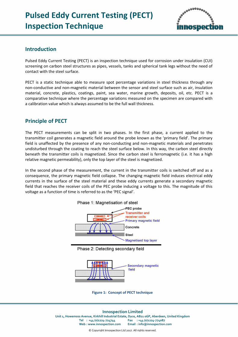
Principle of PECT The PECT measurements can be split in two phases. In the first phase, a current applied to the transmitter coil generates a magnetic field around the probe known as the ‘primary field’. The primary field is unaffected by the presence of any non-conducting and non-magnetic materials and penetrates undisturbed through the coating to reach the steel surface below. In this way, the carbon steel directly beneath the transmitter coils is magnetized. Since the carbon steel is ferromagnetic (i.e. it has a high relative magnetic permeability), only the top layer of the steel is magnetized. In the second phase of the measurement, the current in the transmitter coils is switched off and as a consequence, the primary magnetic field collapse. The changing magnetic field induces electrical eddy currents in the surface of the steel material and these eddy currents generate a secondary magnetic field that reaches the receiver coils of the PEC probe inducing a voltage to this. The magnitude of this voltage as a function of time is referred to as the ‘PEC signal’.
Figure 1: Concept of PECT technique
Pulsed Eddy Current Testing (PECT) Inspection Technique
© Copyright Innospection Ltd 2017. All rights reserved. Page 2 of 12
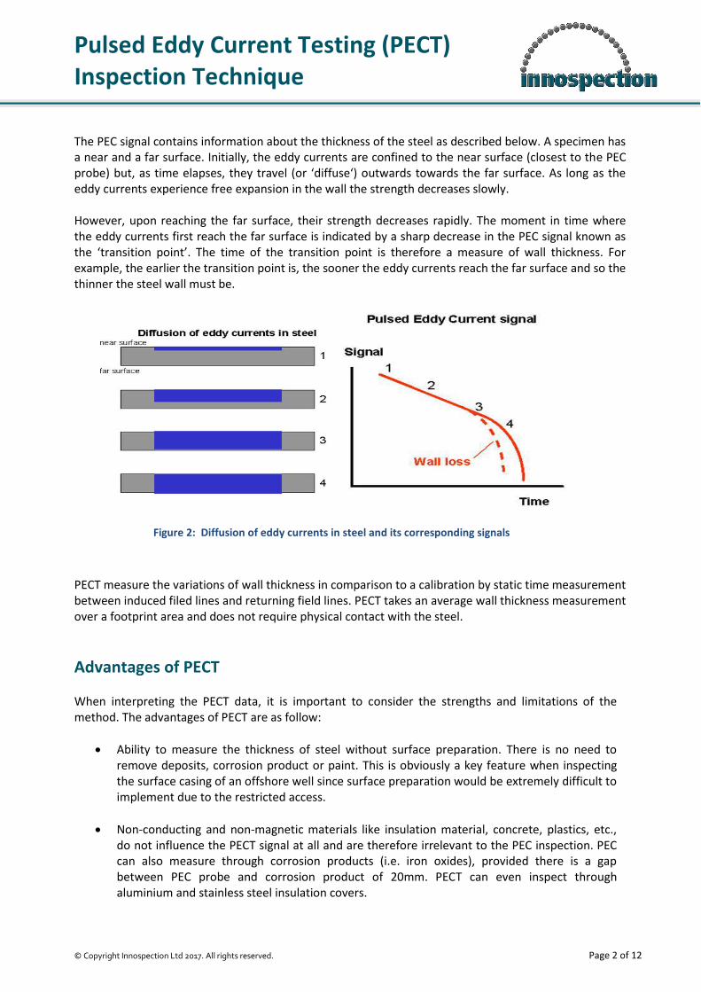
The PEC signal contains information about the thickness of the steel as described below. A specimen has a near and a far surface. Initially, the eddy currents are confined to the near surface (closest to the PEC probe) but, as time elapses, they travel (or ‘diffuse‘) outwards towards the far surface. As long as the eddy currents experience free expansion in the wall the strength decreases slowly. However, upon reaching the far surface, their strength decreases rapidly. The moment in time where the eddy currents first reach the far surface is indicated by a sharp decrease in the PEC signal known as the ‘transition point’. The time of the transition point is therefore a measure of wall thickness. For example, the earlier the transition point is, the sooner the eddy currents reach the far surface and so the thinner the steel wall must be.
PECT measure the variations of wall thickness in comparison to a calibration by static time measurement between induced filed lines and returning field lines. PECT takes an average wall thickness measurement over a footprint area and does not require physical contact with the steel.
Advantages of PECT When interpreting the PECT data, it is important to consider the strengths and limitations of the method. The advantages of PECT are as follow:
Ability to measure the thickness of steel without surface preparation. There is no need to remove deposits, corrosion product or paint. This is obviously a key feature when inspecting the surface casing of an offshore well since surface preparation would be extremely difficult to implement due to the restricted access.
Non-conducting and non-magnetic materials like insulation material, concrete, plastics, etc., do not influence the PECT signal at all and are therefore irrelevant to the PEC inspection. PEC can also measure through corrosion products (i.e. iron oxides), provided there is a gap between PEC probe and corrosion product of 20mm. PECT can even inspect through aluminium and stainless steel insulation covers.
Figure 2: Diffusion of eddy currents in steel and its corresponding signals
Pulsed Eddy Current Testing (PECT) Inspection Technique
© Copyright Innospection Ltd 2017. All rights reserved. Page 3 of 12
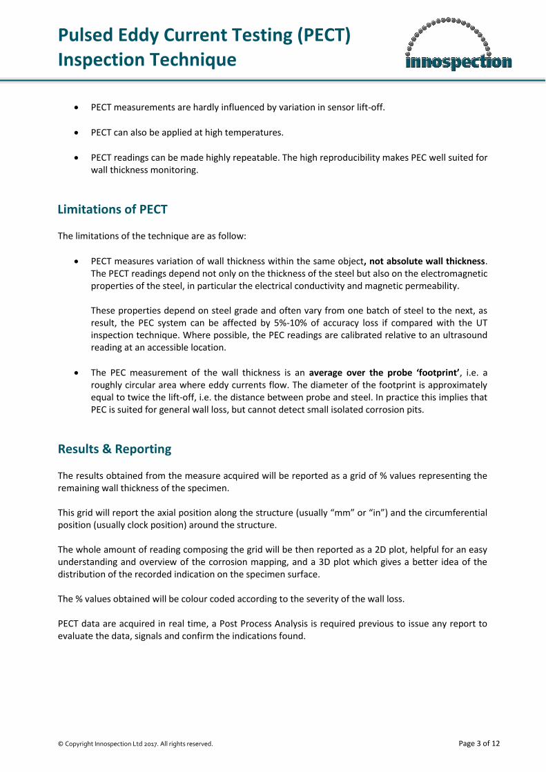
PECT measurements are hardly influenced by variation in sensor lift-off.
PECT can also be applied at high temperatures.
PECT readings can be made highly repeatable. The high reproducibility makes PEC well suited for wall thickness monitoring.
Limitations of PECT The limitations of the technique are as follow:
PECT measures variation of wall thickness within the same object, not absolute wall thickness. The PECT readings depend not only on the thickness of the steel but also on the electromagnetic properties of the steel, in particular the electrical conductivity and magnetic permeability. These properties depend on steel grade and often vary from one batch of steel to the next, as result, the PEC system can be affected by 5%-10% of accuracy loss if compared with the UT inspection technique. Where possible, the PEC readings are calibrated relative to an ultrasound reading at an accessible location.
The PEC measurement of the wall thickness is an average over the probe ‘footprint’, i.e. a roughly circular area where eddy currents flow. The diameter of the footprint is approximately equal to twice the lift-off, i.e. the distance between probe and steel. In practice this implies that PEC is suited for general wall loss, but cannot detect small isolated corrosion pits.
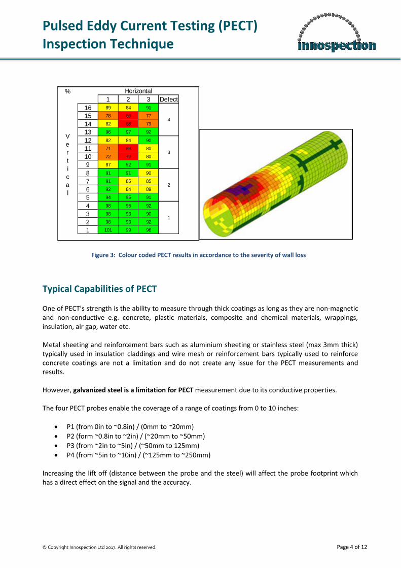
Results & Reporting The results obtained from the measure acquired will be reported as a grid of % values representing the remaining wall thickness of the specimen. This grid will report the axial position along the structure (usually “mm” or “in”) and the circumferential position (usually clock position) around the structure. The whole amount of reading composing the grid will be then reported as a 2D plot, helpful for an easy understanding and overview of the corrosion mapping, and a 3D plot which gives a better idea of the distribution of the recorded indication on the specimen surface. The % values obtained will be colour coded according to the severity of the wall loss. PECT data are acquired in real time, a Post Process Analysis is required previous to issue any report to evaluate the data, signals and confirm the indications found.
Pulsed Eddy Current Testing (PECT) Inspection Technique
© Copyright Innospection Ltd 2017. All rights reserved. Page 4 of 12
Typical Capabilities of PECT One of PECT’s strength is the ability to measure through thick coatings as long as they are non-magnetic and non-conductive e.g. concrete, plastic materials, composite and chemical materials, wrappings, insulation, air gap, water etc. Metal sheeting and reinforcement bars such as aluminium sheeting or stainless steel (max 3mm thick) typically used in insulation claddings and wire mesh or reinforcement bars typically used to reinforce concrete coatings are not a limitation and do not create any issue for the PECT measurements and results. However, galvanized steel is a limitation for PECT measurement due to its conductive properties. The four PECT probes enable the coverage of a range of coatings from 0 to 10 inches:
P1 (from 0in to ~0.8in) / (0mm to ~20mm)
P2 (form ~0.8in to ~2in) / (~20mm to ~50mm)
P3 (from ~2in to ~5in) / (~50mm to 125mm)
P4 (from ~5in to ~10in) / (~125mm to ~250mm) Increasing the lift off (distance between the probe and the steel) will affect the probe footprint which has a direct effect on the signal and the accuracy.
%
1 2 3 Defect
16 89 84 91
15 78 60 77
14 82 68 79
13 96 97 92
12 82 84 90
11 71 69 80
10 72 70 80
9 87 92 91
8 91 91 90
7 91 85 85
6 92 84 89
5 94 95 91
4 98 96 92
3 98 93 90
2 98 93 92
1 101 99 96
Horizontal
V
e
r
t
i
c
a
l
4
3
2
1
Figure 3: Colour coded PECT results in accordance to the severity of wall loss
Pulsed Eddy Current Testing (PECT) Inspection Technique
© Copyright Innospection Ltd 2017. All rights reserved. Page 5 of 12
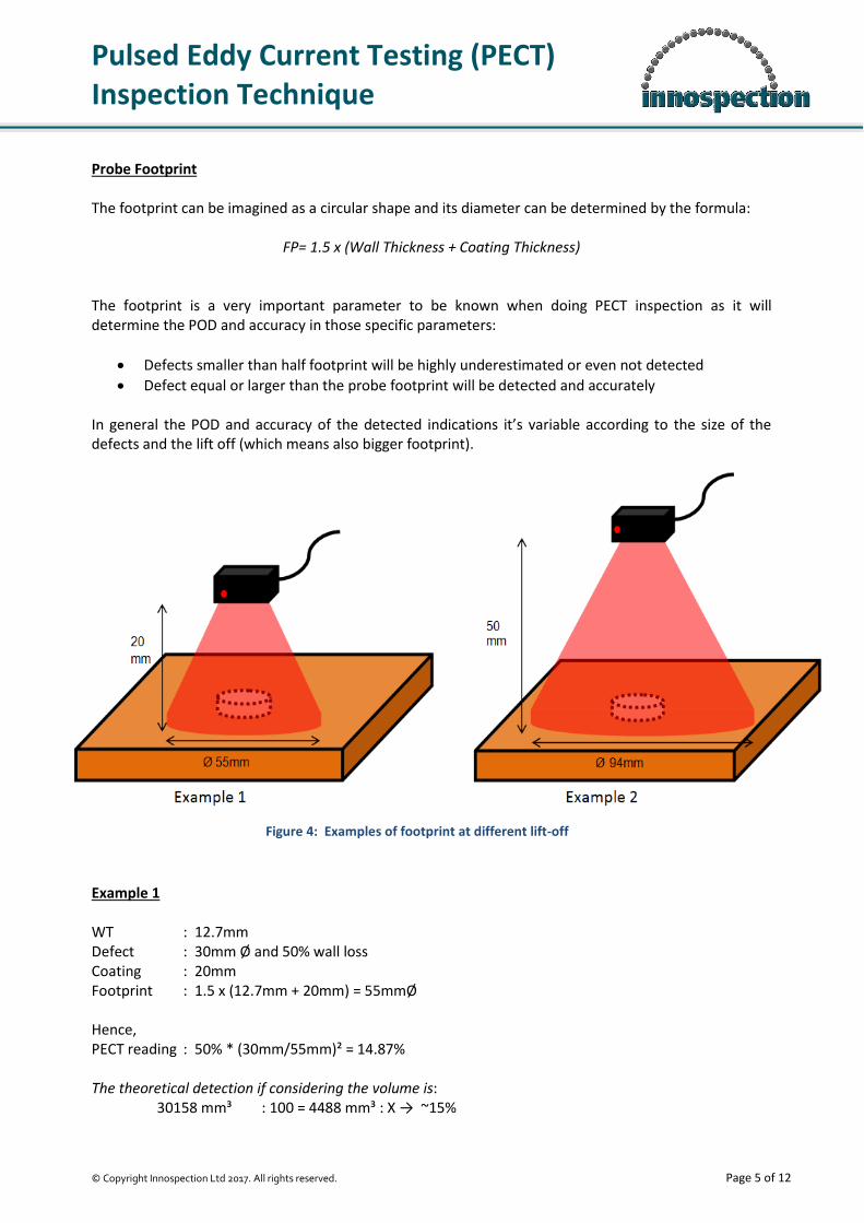
Probe Footprint The footprint can be imagined as a circular shape and its diameter can be determined by the formula:
FP= 1.5 x (Wall Thickness + Coating Thickness) The footprint is a very important parameter to be known when doing PECT inspection as it will determine the POD and accuracy in those specific parameters:
Defects smaller than half footprint will be highly underestimated or even not detected
Defect equal or larger than the probe footprint will be detected and accurately In general the POD and accuracy of the detected indications it’s variable according to the size of the defects and the lift off (which means also bigger footprint). Example 1 WT : 12.7mm Defect : 30mm Ø and 50% wall loss Coating : 20mm Footprint : 1.5 x (12.7mm + 20mm) = 55mmØ Hence, PECT reading : 50% * (30mm/55mm)² = 14.87% The theoretical detection if considering the volume is: 30158 mm³ : 100 = 4488 mm³ : X → ~15%
Figure 4: Examples of footprint at different lift-off
Pulsed Eddy Current Testing (PECT) Inspection Technique
© Copyright Innospection Ltd 2017. All rights reserved. Page 6 of 12
Example 2 WT : 12.7mm Defect : 30mm Ø and 50% wall loss Coating : 50mm Footprint : 1.5 x (12.7mm + 50mm) = 94mmØ Hence, PECT reading : 50% * (30mm/94mm)² = 5% The theoretical detection if considering the volume is: 88090 mm³ : 100 = 4488 mm³ : X → ~5% PECT is not designed for isolated pitting detection but it gives its best performance on general corrosion mapping as the larger the area of corrosion, the more accurate the detection will be. In general, it can be concluded that:
Defect smaller than half footprint will probably not be detected or very underestimated
Defect larger than half footprint or equal to it will be detected but probably underestimated
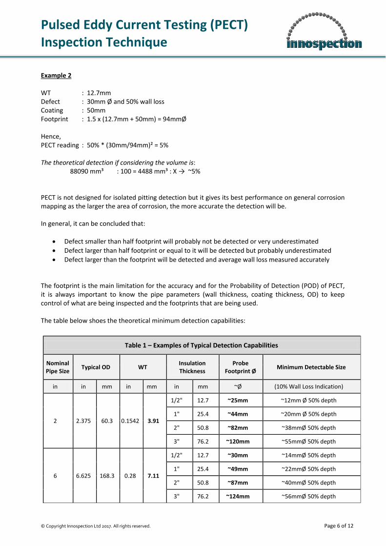
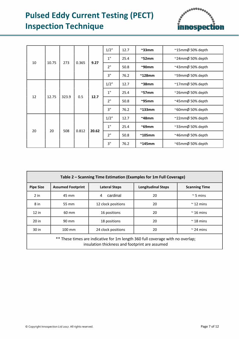
Defect larger than the footprint will be detected and average wall loss measured accurately The footprint is the main limitation for the accuracy and for the Probability of Detection (POD) of PECT, it is always important to know the pipe parameters (wall thickness, coating thickness, OD) to keep control of what are being inspected and the footprints that are being used. The table below shoes the theoretical minimum detection capabilities:
Table 1 – Examples of Typical Detection Capabilities
Nominal Pipe Size
Typical OD WT Insulation Thickness
Probe Footprint Ø
Minimum Detectable Size
in in mm in mm in mm ~Ø (10% Wall Loss Indication)
2 2.375 60.3 0.1542 3.91
1/2" 12.7 ~25mm ~12mm Ø 50% depth
1" 25.4 ~44mm ~20mm Ø 50% depth
2" 50.8 ~82mm ~38mmØ 50% depth
3" 76.2 ~120mm ~55mmØ 50% depth
6 6.625 168.3 0.28 7.11
1/2" 12.7 ~30mm ~14mmØ 50% depth
1" 25.4 ~49mm ~22mmØ 50% depth
2" 50.8 ~87mm ~40mmØ 50% depth
3" 76.2 ~124mm ~56mmØ 50% depth
Pulsed Eddy Current Testing (PECT) Inspection Technique
© Copyright Innospection Ltd 2017. All rights reserved. Page 7 of 12
10 10.75 273 0.365 9.27
1/2" 12.7 ~33mm ~15mmØ 50% depth
1" 25.4 ~52mm ~24mmØ 50% depth
2" 50.8 ~90mm ~43mmØ 50% depth
3" 76.2 ~128mm ~59mmØ 50% depth
12 12.75 323.9 0.5 12.7
1/2" 12.7 ~38mm ~17mmØ 50% depth
1" 25.4 ~57mm ~26mmØ 50% depth
2" 50.8 ~95mm ~45mmØ 50% depth
3" 76.2 ~133mm ~60mmØ 50% depth
20 20 508 0.812 20.62
1/2" 12.7 ~48mm ~22mmØ 50% depth
1" 25.4 ~69mm ~33mmØ 50% depth
2" 50.8 ~105mm ~46mmØ 50% depth
3" 76.2 ~145mm ~65mmØ 50% depth
Table 2 – Scanning Time Estimation (Examples for 1m Full Coverage)
Pipe Size Assumed Footprint Lateral Steps Longitudinal Steps Scanning Time
2 in 45 mm 4 cardinal 20 ~ 5 mins
8 in 55 mm 12 clock positions 20 ~ 12 mins
12 in 60 mm 16 positions 20 ~ 16 mins
20 in 90 mm 18 positions 20 ~ 18 mins
30 in 100 mm 24 clock positions 20 ~ 24 mins
** These times are indicative for 1m length 360 full coverage with no overlap; insulation thickness and footprint are assumed
Pulsed Eddy Current Testing (PECT) Inspection Technique
© Copyright Innospection Ltd 2017. All rights reserved. Page 8 of 12
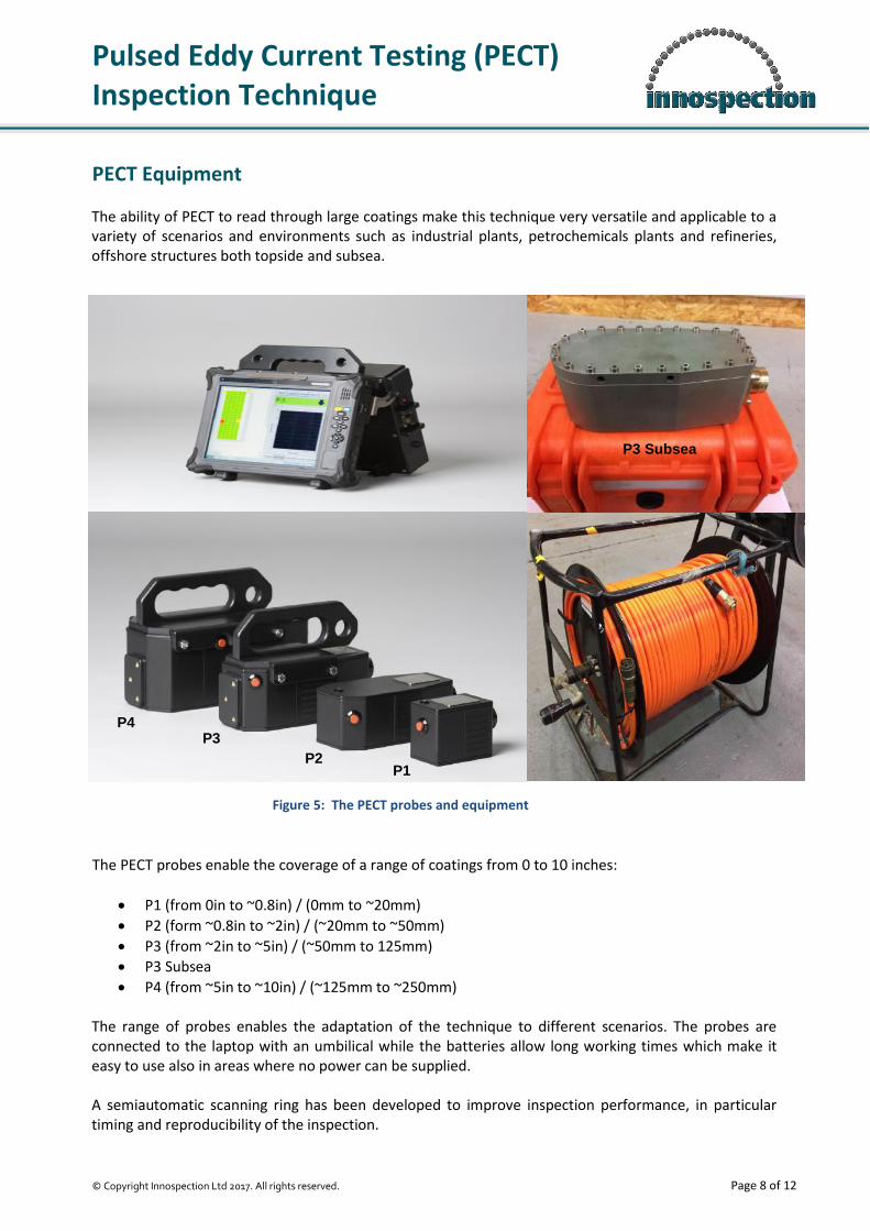
PECT Equipment The ability of PECT to read through large coatings make this technique very versatile and applicable to a variety of scenarios and environments such as industrial plants, petrochemicals plants and refineries, offshore structures both topside and subsea. The PECT probes enable the coverage of a range of coatings from 0 to 10 inches:
P1 (from 0in to ~0.8in) / (0mm to ~20mm)
P2 (form ~0.8in to ~2in) / (~20mm to ~50mm)
P3 (from ~2in to ~5in) / (~50mm to 125mm)
P3 Subsea
P4 (from ~5in to ~10in) / (~125mm to ~250mm) The range of probes enables the adaptation of the technique to different scenarios. The probes are connected to the laptop with an umbilical while the batteries allow long working times which make it easy to use also in areas where no power can be supplied. A semiautomatic scanning ring has been developed to improve inspection performance, in particular timing and reproducibility of the inspection.
P3 Subsea
P1 P2
P3 P4
Figure 5: The PECT probes and equipment
Pulsed Eddy Current Testing (PECT) Inspection Technique
© Copyright Innospection Ltd 2017. All rights reserved. Page 9 of 12
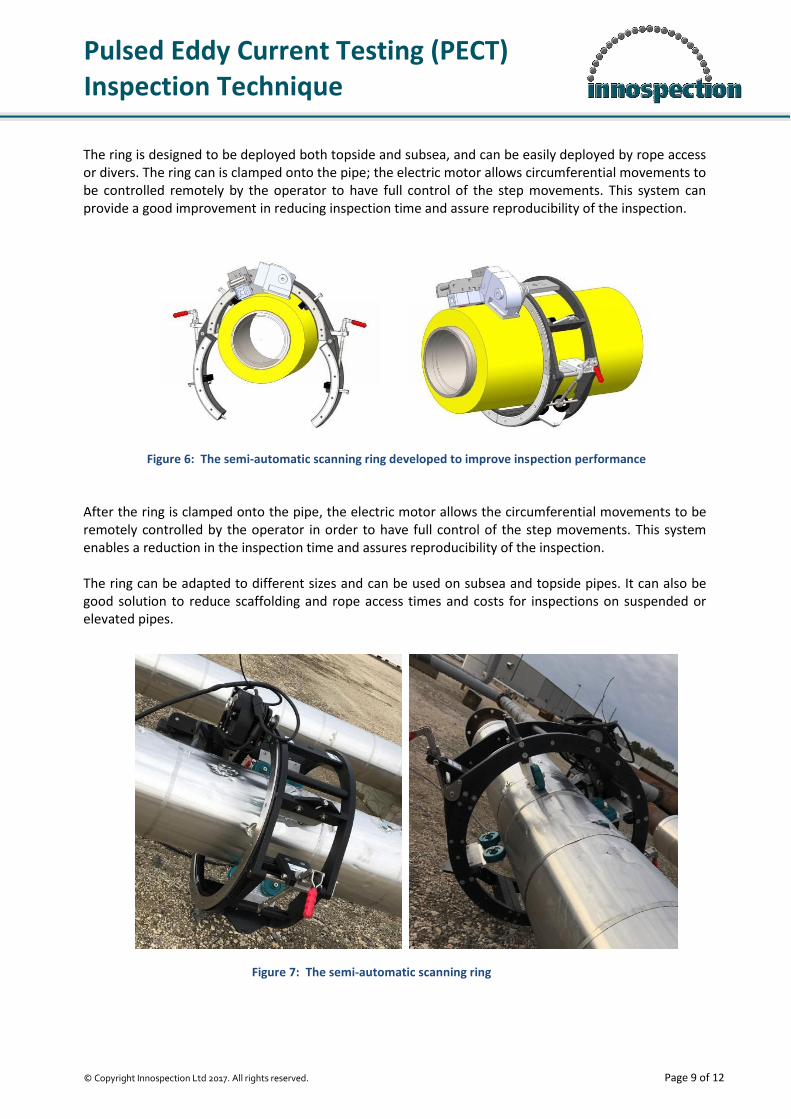
The ring is designed to be deployed both topside and subsea, and can be easily deployed by rope access or divers. The ring can is clamped onto the pipe; the electric motor allows circumferential movements to be controlled remotely by the operator to have full control of the step movements. This system can provide a good improvement in reducing inspection time and assure reproducibility of the inspection. After the ring is clamped onto the pipe, the electric motor allows the circumferential movements to be remotely controlled by the operator in order to have full control of the step movements. This system enables a reduction in the inspection time and assures reproducibility of the inspection. The ring can be adapted to different sizes and can be used on subsea and topside pipes. It can also be good solution to reduce scaffolding and rope access times and costs for inspections on suspended or elevated pipes.
Figure 6: The semi-automatic scanning ring developed to improve inspection performance
Figure 7: The semi-automatic scanning ring

Pulsed Eddy Current Testing (PECT) Inspection Technique
© Copyright Innospection Ltd 2017. All rights reserved. Page 10 of 12
Topside Applications of PECT PECT is a versatile inspection technique that can be applied in different working scenarios and environments such as industrial plant, petrochemical plants, refineries, platforms topside and subsea pipes, storage tanks and insulated pressure vessel.
Corrosion Under Insulation (CUI) CUI is a big challenge for the inspection and asset integrity management. Insulated pipes can be found in a variety of production environments such as industrial plants, petrochemical plants, refineries and platforms. The ability to read through thick coatings and not being affected by the usual aluminium or stainless steel sheeting covering these pipes makes PECT a perfect solution for CUI.
Insulated Pressure Vessels Insulated pressure vessels can be inspected with the PECT technique. Insulated pressure vessels can be considered as insulated pipes and the stainless steel or aluminium external sheeting is not a limitation for PECT. Only galvanized sheeting cannot be inspected by PECT.
Insulated Tanks Insulated tanks can also be inspected using PECT. The inspection can be carried out from external wall to corrosion screening the internal wall of the tank. Particular attention must be taken during inspection of tanks to consider structure inside the insulation layers that may have an effect on the PECT readings.

Pulsed Eddy Current Testing (PECT) Inspection Technique
© Copyright Innospection Ltd 2017. All rights reserved. Page 11 of 12
Spherical Tank Legs Concreted coated spherical tank legs are subjected to huge stress and their integrity is crucial and needs to be assessed. PECT is again a fast and cost effective method for corrosion screening on these structures due to its capability of inspection without the removal of the concrete coating.
Composite Repairs Composite materials usually used for repairing damaged or corroded areas on pipes can be a limitation for other inspection techniques but not for PECT. PECT can be used to map the area of corrosion and monitor it periodically to evaluate changes in its shape and severity. It might help to keep the assets working time as long as possible.
Splash Zone & Subsea Applications of PECT The PECT technique with its ability to inspect through thick coatings without the need for coating removal makes it uniquely suitable for offshore, splash zone and subsea applications.
Concrete Coated & Reinforced Concrete Coated Subsea Pipelines Subsea pipelines are usually reinforced with concrete coating which are often further reinforced with bars or wire mesh placed in the middle of the coating. PECT has the capability to inspect through these reinforcements to provide information on the pipe status without the need for the concrete removal. Hence, it offers a cost and time effective inspection operation.

Pulsed Eddy Current Testing (PECT) Inspection Technique
© Copyright Innospection Ltd 2017. All rights reserved. Page 12 of 12
Risers, Caissons & Conductors PECT is a suitable technique for the splash zone and subsea inspection of the typically coated risers, caissons and conductors. The light weight of PECT probes allows them to be easily deployed by rope access personnel to perform inspection on risers, caissons, conductors and other vertical or elevated structures which are easily assessable.