Embed Size (px)
Citation preview
ECONOFLAME R300 GAS FIRED CONDENSING
HEATING/HOT WATER BOILERS (INCLUDING SUPPLEMENT)
INSTALLATION, OPERATION & MAINTENANCE
DOCUMENTATION
STOKVIS ENERGY SYSTEMS 96R WALTON ROAD EAST MOLESEY SURREY KT8 0DL TEL: 020 8783 3050 / 08707 707 747 FAX: 020 8783 3051 / 08707 707 767 E-MAIL: [email protected] WEBSITE: www.stokvisboilers.com
50CV02B&C 180504

50CV02BII
Edition 50CV02B, 17-06-2001
© 2001 Stokvis.
All rights reserved.No part of this publication may be reproduced, stored in a retrieval system, or transmitted inany form or by any means, electronic, mechanical, photocopying, recording or otherwise,without the prior permission in writing of Stokvis .
We aim to achieve continuous improvement in our products. Therefore, specifications aresubject to change without prior notice.
Due to changes the product can deviate from the information specified in this document.Therefore Stokvis rejects any responsibility for the differences between theproduct delivered and the information mentioned in this document.
50CV02B III
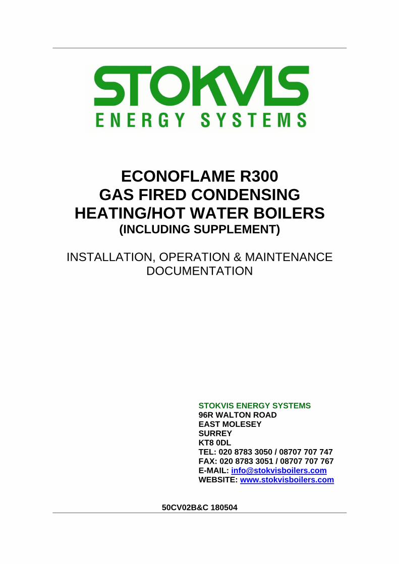
R300 TECHNICAL DATA
Type R301 R302 R303 R304 R305 R306 R307
Nominal heat output kW 70 86 114 139 185 230 274Nominal heat input (nett. CV) kW 74 91 121 147 194 243 289Minimum heat output kW 16 20 27 33 44 55 65
Gas consumptionnatural gas H (10,9 kWh/m ) m /h 6,79 8,35 11,10 13,49 17,80 22,29 26,513
propane (12,8 kWh/kg) kg/h 5,78 7,11 9,45 11,48 15,16 18,98 22,58
3
Gas inlet pressure natural gas (min.) mbar 17 17 17 17 17 17 17
natural gas (max.) mbar 25 25 25 25 25 25 25propane mbar 50 50 50 50 50 50 50
Water capacity dm 13 15 17 19 36 39 42Max. working pressure bar 6 6 6 6 6 6 6
3
Flue connection D mm 100 100 100 150 180 200 200Air supply (option) D1 mm 100 100 100 125 150 180 180
Gas connection G Rp¾" Rp¾" Rp¾" Rp¾" R1" R1½" R1½"
Water connections W R1½" R1½" R1½" R1½" R2" R2" R2"
Safety valve boiler connection ¾" ¾" ¾" ¾" ¾" 1" 1"(option) relief connection ¾" ¾" ¾" ¾" ¾" 1¼" 1¼"
standard setting bar 3 3 3 3 3 3 3
Power supply V 230 1N~ 230 1N~ 230 1N~ 230 1N~ 230 1N~ 230 1N~ 230 1N~Frequency Hz 50 50 50 50 50 50 50Fuse A 10 10 10 10 10 10 10
Max. electrical power consumptionunit W 135 135 370 370 370 370 370
pump (option) maximum W 245 245 245 245 380 380 380total W 380 380 615 615 750 750 750
Boiler weight, empty, ± 5 % kg 120 140 160 180 250 270 290
Table 1 Technical data R300
50CV02BIV
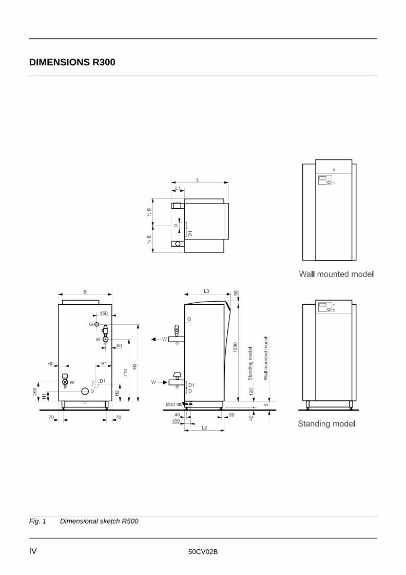
Fig. 1 Dimensional sketch R500
DIMENSIONS R300
50CV02B V
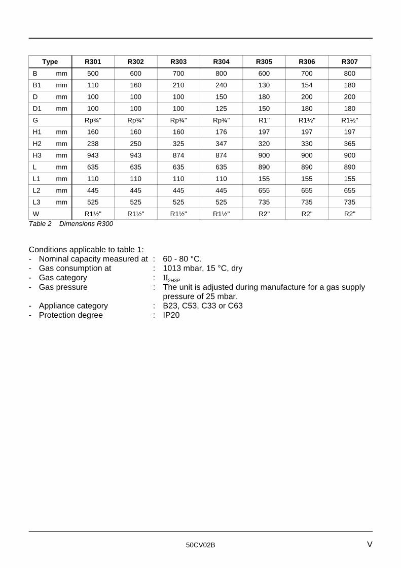
Type R301 R302 R303 R304 R305 R306 R307B mm 500 600 700 800 600 700 800
B1 mm 110 160 210 240 130 154 180
D mm 100 100 100 150 180 200 200
D1 mm 100 100 100 125 150 180 180
G Rp¾" Rp¾" Rp¾" Rp¾" R1" R1½" R1½"
H1 mm 160 160 160 176 197 197 197
H2 mm 238 250 325 347 320 330 365
H3 mm 943 943 874 874 900 900 900
L mm 635 635 635 635 890 890 890
L1 mm 110 110 110 110 155 155 155
L2 mm 445 445 445 445 655 655 655
L3 mm 525 525 525 525 735 735 735
W R1½" R1½" R1½" R1½" R2" R2" R2"Table 2 Dimensions R300
Conditions applicable to table 1:- Nominal capacity measured at : 60 - 80 °C.- Gas consumption at : 1013 mbar, 15 °C, dry- Gas category : II2H3P- Gas pressure : The unit is adjusted during manufacture for a gas supply
pressure of 25 mbar.- Appliance category : B23, C53, C33 or C63- Protection degree : IP20

50CV02BVI
50CV02B
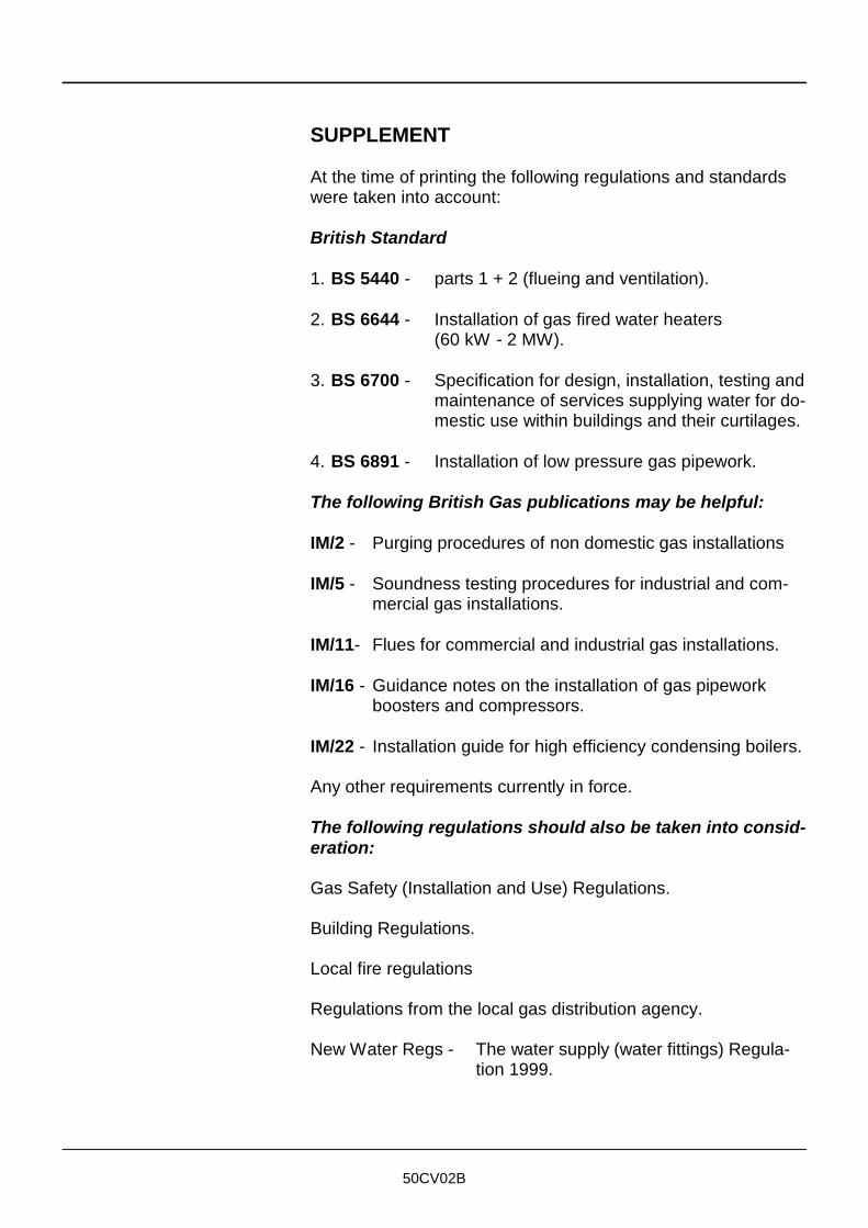
SUPPLEMENT
At the time of printing the following regulations and standardswere taken into account:
British Standard
1. BS 5440 - parts 1 + 2 (flueing and ventilation).
2. BS 6644 - Installation of gas fired water heaters (60 kW - 2 MW).
3. BS 6700 - Specification for design, installation, testing andmaintenance of services supplying water for do-mestic use within buildings and their curtilages.
4. BS 6891 - Installation of low pressure gas pipework.
The following British Gas publications may be helpful:
IM/2 - Purging procedures of non domestic gas installations
IM/5 - Soundness testing procedures for industrial and com-mercial gas installations.
IM/11- Flues for commercial and industrial gas installations.
IM/16 - Guidance notes on the installation of gas pipeworkboosters and compressors.
IM/22 - Installation guide for high efficiency condensing boilers.
Any other requirements currently in force.
The following regulations should also be taken into consid-eration:
Gas Safety (Installation and Use) Regulations.
Building Regulations.
Local fire regulations
Regulations from the local gas distribution agency.
New Water Regs - The water supply (water fittings) Regula-tion 1999.

50CV02B
50CV02C VII
TABLE OF CONTENTS
R300 Technical data . . . . . . . . . . . . . . . . . . . . . . . . . IIIDimensions R300 . . . . . . . . . . . . . . . . . . . . . . . . . . . IVTable of contents . . . . . . . . . . . . . . . . . . . . . . . . . . . VII
1 INTRODUCTION . . . . . . . . . . . . . . . . . . . . . . . . . . . . 11.1 Stokvis . . . . . . . . . . . . . . . . . . . . . . . . . . . . . . . . . . . . 11.2 Supplier . . . . . . . . . . . . . . . . . . . . . . . . . . . . . . . . . . . 11.3 This document . . . . . . . . . . . . . . . . . . . . . . . . . . . . . . 11.4 Service . . . . . . . . . . . . . . . . . . . . . . . . . . . . . . . . . . . . 21.5 General restrictions . . . . . . . . . . . . . . . . . . . . . . . . . . 2
2 DESCRIPTION . . . . . . . . . . . . . . . . . . . . . . . . . . . . . 32.1 General . . . . . . . . . . . . . . . . . . . . . . . . . . . . . . . . . . . 32.2 Main components . . . . . . . . . . . . . . . . . . . . . . . . . . . . 52.2.1 Description of principal components . . . . . . . . . . . . . 62.3 Boiler control . . . . . . . . . . . . . . . . . . . . . . . . . . . . . . . 82.4 Safety aspects . . . . . . . . . . . . . . . . . . . . . . . . . . . . . . 8
3 SAFETY . . . . . . . . . . . . . . . . . . . . . . . . . . . . . . . . . . . 9
4 DELIVERY AND TRANSPORT . . . . . . . . . . . . . . . . 124.1 Delivery . . . . . . . . . . . . . . . . . . . . . . . . . . . . . . . . . . 124.2 Packaging . . . . . . . . . . . . . . . . . . . . . . . . . . . . . . . . 124.3 Transport . . . . . . . . . . . . . . . . . . . . . . . . . . . . . . . . . 12
5 INSTALLATION . . . . . . . . . . . . . . . . . . . . . . . . . . . . 135.1 Regulations . . . . . . . . . . . . . . . . . . . . . . . . . . . . . . . 135.2 Boiler room . . . . . . . . . . . . . . . . . . . . . . . . . . . . . . . . 135.2.1 General . . . . . . . . . . . . . . . . . . . . . . . . . . . . . . . . . . 135.2.2 Set up . . . . . . . . . . . . . . . . . . . . . . . . . . . . . . . . . . . 135.2.3 Ventilation . . . . . . . . . . . . . . . . . . . . . . . . . . . . . . . . 145.3 Connections . . . . . . . . . . . . . . . . . . . . . . . . . . . . . . . 145.3.1 Gas connection . . . . . . . . . . . . . . . . . . . . . . . . . . . . 145.3.2 Electrical connection . . . . . . . . . . . . . . . . . . . . . . . . 145.3.3 Water connections . . . . . . . . . . . . . . . . . . . . . . . . . . 195.3.4 Combustion air supply . . . . . . . . . . . . . . . . . . . . . . . 205.3.4.1 General . . . . . . . . . . . . . . . . . . . . . . . . . . . . . . . . . . 205.3.4.2 Air supply pipe . . . . . . . . . . . . . . . . . . . . . . . . . . . . . 205.3.5 The flue system . . . . . . . . . . . . . . . . . . . . . . . . . . . . 225.3.5.1 General . . . . . . . . . . . . . . . . . . . . . . . . . . . . . . . . . . 225.3.5.2 Chimney . . . . . . . . . . . . . . . . . . . . . . . . . . . . . . . . . . 225.3.6 Condensate discharge . . . . . . . . . . . . . . . . . . . . . . . 24
50CV02CVIII
5.4 Hydraulic system . . . . . . . . . . . . . . . . . . . . . . . . . . . 255.4.1 General . . . . . . . . . . . . . . . . . . . . . . . . . . . . . . . . . . 255.4.2 Water flow . . . . . . . . . . . . . . . . . . . . . . . . . . . . . . . . 255.4.2.1 Flow rate and resistance . . . . . . . . . . . . . . . . . . . . . 255.4.2.2 Pump characteristics . . . . . . . . . . . . . . . . . . . . . . . . 275.4.2.3 Isolating valves . . . . . . . . . . . . . . . . . . . . . . . . . . . . 295.4.2.4 Valves . . . . . . . . . . . . . . . . . . . . . . . . . . . . . . . . . . . 295.4.2.5 Water flow protection . . . . . . . . . . . . . . . . . . . . . . . . 295.4.3 Water pressure . . . . . . . . . . . . . . . . . . . . . . . . . . . . 295.4.3.1 Operating pressure . . . . . . . . . . . . . . . . . . . . . . . . . 295.4.3.2 Boiler expansion tank . . . . . . . . . . . . . . . . . . . . . . . . 295.4.3.3 System expansion tank . . . . . . . . . . . . . . . . . . . . . . 295.4.3.4 Water pressure protection . . . . . . . . . . . . . . . . . . . . 295.4.4 Water temperature . . . . . . . . . . . . . . . . . . . . . . . . . . 295.4.5 Water quality . . . . . . . . . . . . . . . . . . . . . . . . . . . . . . 295.4.6 Examples of hydraulic systems . . . . . . . . . . . . . . . . 31
6 OPERATING INSTRUCTIONS . . . . . . . . . . . . . . . . 356.1 Function . . . . . . . . . . . . . . . . . . . . . . . . . . . . . . . . . . 356.2 Regulation . . . . . . . . . . . . . . . . . . . . . . . . . . . . . . . . 356.3 Control module . . . . . . . . . . . . . . . . . . . . . . . . . . . . . 356.4 Fault indications . . . . . . . . . . . . . . . . . . . . . . . . . . . . 386.5 Start-up . . . . . . . . . . . . . . . . . . . . . . . . . . . . . . . . . . 396.6 Shut-down . . . . . . . . . . . . . . . . . . . . . . . . . . . . . . . . 396.7 Warnings . . . . . . . . . . . . . . . . . . . . . . . . . . . . . . . . . 39
7 COMMISSIONING . . . . . . . . . . . . . . . . . . . . . . . . . . 407.1 General . . . . . . . . . . . . . . . . . . . . . . . . . . . . . . . . . . 407.2 Commissioning . . . . . . . . . . . . . . . . . . . . . . . . . . . . 40
8 MAINTENANCE . . . . . . . . . . . . . . . . . . . . . . . . . . . 448.1 Safety . . . . . . . . . . . . . . . . . . . . . . . . . . . . . . . . . . . . 448.2 General . . . . . . . . . . . . . . . . . . . . . . . . . . . . . . . . . . 448.3 Procedure . . . . . . . . . . . . . . . . . . . . . . . . . . . . . . . . 448.4 Cleaning the burner and heat exchangers . . . . . . . . 458.5 Cleaning the filter/screen in the gas
combination block . . . . . . . . . . . . . . . . . . . . . . . . . . 458.6 Ionisation measurement . . . . . . . . . . . . . . . . . . . . . . 458.7 Service . . . . . . . . . . . . . . . . . . . . . . . . . . . . . . . . . . . 45
9 CONVERSION FORMULAE AND FACTORS . . . . . 46
SUPPLEMENT
Edition 50CV02C, 31-10-2001
© 2001 Stokvis
50CV02C 1
1 INTRODUCTION
1.1 Stokvis. Since its beginning in 1985, Stokvis has built up a strong reputation in industry for the development, produc-
tion and marketing of gas-fired, high efficiency boilers andISO9002 water heaters in the 60 to 1200 kW range.
1.2 Supplier STOKVIS ENERGY SYSTEMS
1.3 This document This documentation has been produced to aid the following
Through their unique construction, these central heating unitsand water heaters are renowned for their:- high thermal efficiency- environmental friendliness- light weight and small dimensions- durability- low noise production- large regulating range- available with many different options.
Continual research and development means that Stokvis remains at the forefront of boiler technology.
96R Walton Road, East MoleseySurrey KT8 0DLTel.: 08707 707 747Fax: 08707 707 767
target groups:- the consulting engineer- the heating installer- the service engineer- the user.
Because these target groups require mostly similar informationand also specific information, our technical documentation hasbeen integrated to provide these target groups with the neces-sary general and specific information to install, service andoperate this product.The supplier (see 1.2) will be able to provide any further orsupplemental information.
50CV02C2
1.4 Service The Stokvis service department is always
1.5 General restrictions The application, installation and maintenance of Stokvis
The following aspects of the units are dealt with:- General description- Technical specifications- The facilities necessary for design and installation- Installation examples- Maintenance instructions.
The operating instructions needed by the user are attached tothe unit; these are also to be found in Section 6.
available for commissioning and for providing service andmaintenance. For details see 1.2.
products must always be carried out in accordancewith the requirements (legal or otherwise), specifications andstandards applicable to such installations.
All data, information and suggestions provided by Stokvisin relation to its products are based on carefulinvestigation. Nevertheless, neither Stokvis nor any other organisation connected with Stokvis accepts any liability for application, installation that occursoutside its sphere of influence.
Changes may be incorporated without prior notice. Stokvis accepts no obligation to adaptpreviously delivered products to incorporate suchchanges.
50CV02C 3
2 DESCRIPTION
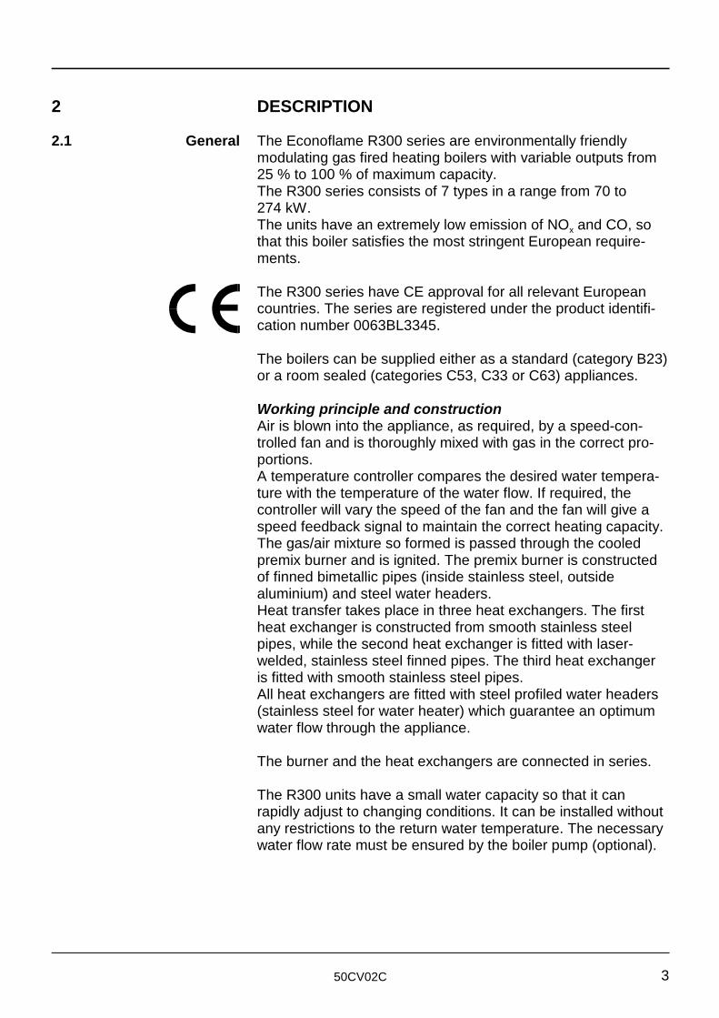
2.1 General The Econoflame R300 series are environmentally friendly
The R300 series have CE approval for all relevant European
modulating gas fired heating boilers with variable outputs from25 % to 100 % of maximum capacity. The R300 series consists of 7 types in a range from 70 to 274 kW.The units have an extremely low emission of NO and CO, soxthat this boiler satisfies the most stringent European require-ments.
countries. The series are registered under the product identifi-cation number 0063BL3345.
The boilers can be supplied either as a standard (category B23)or a room sealed (categories C53, C33 or C63) appliances.
Working principle and constructionAir is blown into the appliance, as required, by a speed-con-trolled fan and is thoroughly mixed with gas in the correct pro-portions.A temperature controller compares the desired water tempera-ture with the temperature of the water flow. If required, thecontroller will vary the speed of the fan and the fan will give aspeed feedback signal to maintain the correct heating capacity.The gas/air mixture so formed is passed through the cooledpremix burner and is ignited. The premix burner is constructedof finned bimetallic pipes (inside stainless steel, outsidealuminium) and steel water headers.Heat transfer takes place in three heat exchangers. The firstheat exchanger is constructed from smooth stainless steelpipes, while the second heat exchanger is fitted with laser-welded, stainless steel finned pipes. The third heat exchangeris fitted with smooth stainless steel pipes.All heat exchangers are fitted with steel profiled water headers(stainless steel for water heater) which guarantee an optimumwater flow through the appliance.
The burner and the heat exchangers are connected in series.
The R300 units have a small water capacity so that it canrapidly adjust to changing conditions. It can be installed withoutany restrictions to the return water temperature. The necessarywater flow rate must be ensured by the boiler pump (optional).
50CV02C4
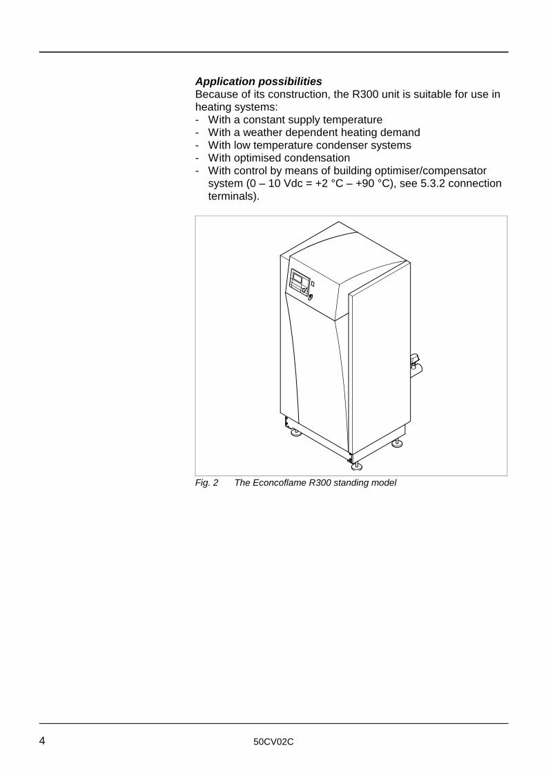
Fig. 2 The Econcoflame R300 standing model
Application possibilitiesBecause of its construction, the R300 unit is suitable for use inheating systems:- With a constant supply temperature- With a weather dependent heating demand- With low temperature condenser systems- With optimised condensation- With control by means of building optimiser/compensator
system (0 – 10 Vdc = +2 °C – +90 °C), see 5.3.2 connectionterminals).
50CV02C 5
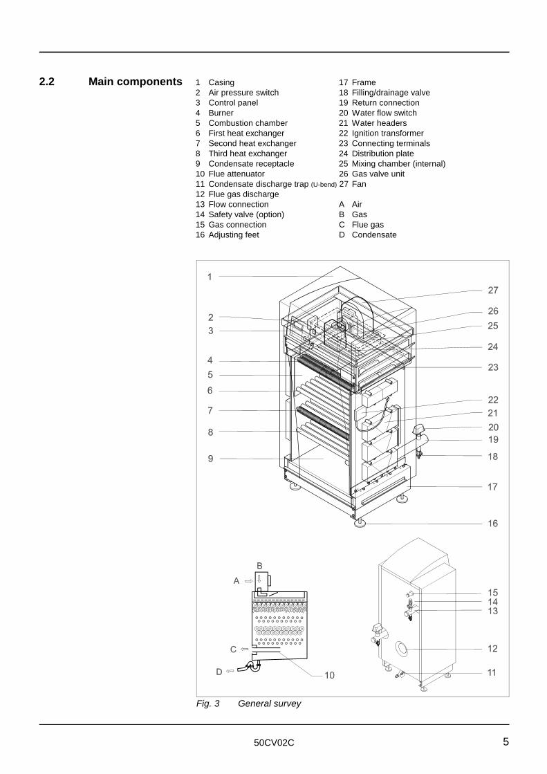
Fig. 3 General survey
2.2 Main components 1 Casing 17 Frame2 Air pressure switch 18 Filling/drainage valve3 Control panel 19 Return connection4 Burner 20 Water flow switch5 Combustion chamber 21 Water headers6 First heat exchanger 22 Ignition transformer7 Second heat exchanger 23 Connecting terminals8 Third heat exchanger 24 Distribution plate9 Condensate receptacle 25 Mixing chamber (internal)10 Flue attenuator 26 Gas valve unit11 Condensate discharge trap (U-bend) 27 Fan12 Flue gas discharge13 Flow connection A Air14 Safety valve (option) B Gas15 Gas connection C Flue gas16 Adjusting feet D Condensate
50CV02C6
2.2.1 Description of The boiler is constructed from the following principal compo-principal components nents:
Fan [27]The DC fan, which is equipped with speed feedback, draws inthe combustion air and increases the air pressure. The speedfeedback signal is relayed to the regulator, which adjusts thespeed if need be.
Gas train The principal component of the gas train is the main gas valve[26]. The quantity of gas is adjusted in proportion to the quantityof air being supplied. The quantity of air depends on the speedof the fan. As an option, the unit can be equipped with a gasfilter.
Mixing chamber [30]This area is used for the thorough mixing of the gas and thecombustion air. The chamber is situated inside the unit.
Burner [4]After the gas/air mixture has been distributed over the burnerusing a distribution plate, the mixture is burnt on the burnersurface such that the flame is directed downward. The burner isboth air and water-cooled. The water headers are constructedof steel (stainless steel for water heater), and ensure a two-pass flow through the burner.
Heat exchangers [6, 7 and 8]The first heat exchanger is constructed of smooth stainlesssteel pipes and transfers most of the combustion energy to thesystem water. The second heat exchanger is constructed oflaser-welded, stainless steel finned pipes. The third heatexchanger is constructed of smooth stainless steel pipes. Thesecond and third heat exchanger transfer the heat from thecombustion gasses to the system water. All water headers areconstructed of steel (stainless steel for water heaters), andensure a five-pass or three-pass flow through the heatexchangers (depending on the type). The space between theburner and the first heat exchanger constitutes the combustionchamber.
Water headers [21]The water headers are part of the burner and the heatexchangers.
50CV02C 7
Water connectionsThese consist of a flow connection [13] and a return connection[19]. Both of these connections are provided with a filling/drainvalve [18]. The connection for the optional safety valve [14] isfitted on the supply line. The flow switch [20] is fitted on thereturn line.
Boiler pump (optional)The boiler pump must be mounted on the return connection tothe unit and can be directly connected electrically to theappropriate terminals in the connection box. The capacity andthe working head of the pump is sufficient to overcome both theresistance of the boiler and some system resistance. As anoption, the pump is supplied as a separate item with the boiler.
Condensate receptacle [9]A condensate receptacle is fitted underneath the last heatexchanger. This receptacle is equipped with a condensate andflue gas outlet.
Frame [17]The frame is constructed from steel profile sections and is fittedwith vibration absorbing adjusting feet [16].
Casing [1]The casing consists of easy-to-remove panels. Once the coverhas been opened (using tools), all other panels can beremoved without using tools.
The electrical sectionThis includes the control and safety circuits for the unit.
Connecting terminals [23]The boiler power supply, the connecting terminals, the pumpconnection and the pump relay are all fitted on top of the boiler.The terminal strip is located under the cover, on the right handside.
50CV02C8
2.3 Boiler control The principle employed for the Boiler Management Unit is as
2.4 Safety aspects The boiler contains the following safety components:
follows: The boiler begins operating on receipt of a heatingdemand. This heating demand is generated either:A If the measured supply temperature is lower than the
desired temperatureB As a result of “service operation” mode having been
selected (j)C in standby mode, when the water temperature falls below
the frost protection temperature.
After the unit has started up, the PID controller sends a signalto the fan, thus controlling the fan speed. Depending on thequantity of air displaced by the fan, the proportional pressureregulator will add the corresponding quantity of gas. In this way,the boiler power is continuously modulated, enabling the boilerto accurately follow the demand for heat. The fan is equippedwith a speed feedback, enabling an even more accurate controlbehaviour. Once the supply water temperature exceeds the desired value,the unit will shut down. As soon as the supply watertemperature falls below the set value, the boiler re-starts.
- Flame protection (1x re-start)- Water flow protection- Maximum water temperature protection- Gas valve test- overload and underload protection.
If one of these components operates, this results in a lockoutfault. Lockout faults can only be cancelled by resetting the unit.
50CV02C 9
3 SAFETY
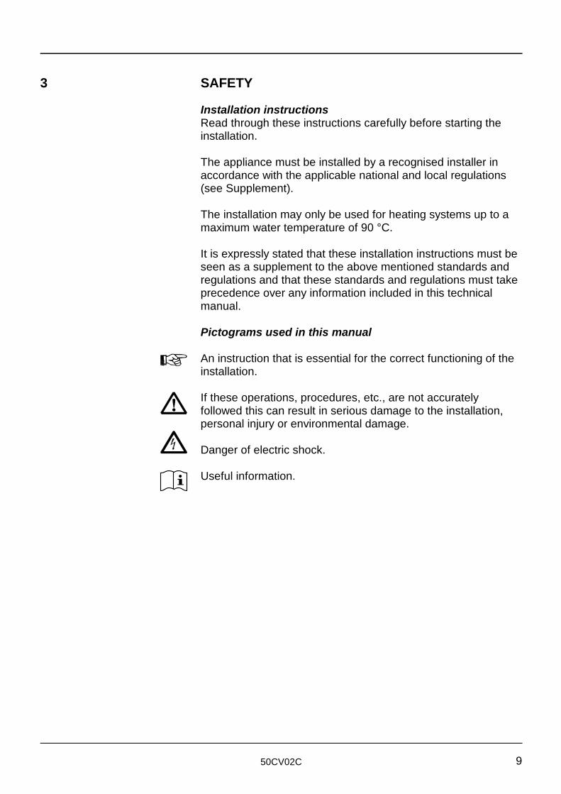
Pictograms used in this manual
An instruction that is essential for the correct functioning of the
If these operations, procedures, etc., are not accurately
Useful information.
Installation instructionsRead through these instructions carefully before starting theinstallation.
The appliance must be installed by a recognised installer inaccordance with the applicable national and local regulations(see Supplement).
The installation may only be used for heating systems up to amaximum water temperature of 90 °C.
It is expressly stated that these installation instructions must beseen as a supplement to the above mentioned standards andregulations and that these standards and regulations must takeprecedence over any information included in this technicalmanual.
installation.
followed this can result in serious damage to the installation,personal injury or environmental damage.
Danger of electric shock.
50CV02C10
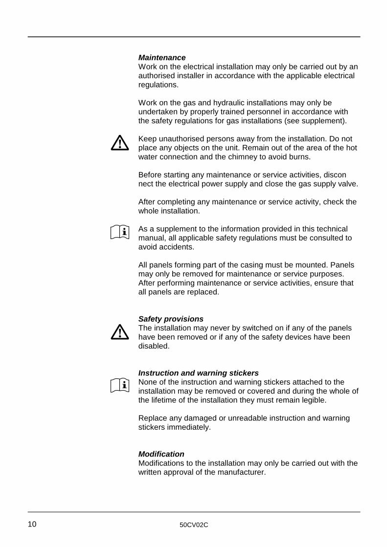
Keep unauthorised persons away from the installation. Do not
As a supplement to the information provided in this technical
The installation may never by switched on if any of the panels
None of the instruction and warning stickers attached to the
MaintenanceWork on the electrical installation may only be carried out by anauthorised installer in accordance with the applicable electricalregulations.
Work on the gas and hydraulic installations may only beundertaken by properly trained personnel in accordance withthe safety regulations for gas installations (see supplement).
place any objects on the unit. Remain out of the area of the hotwater connection and the chimney to avoid burns.
Before starting any maintenance or service activities, disconnect the electrical power supply and close the gas supply valve.
After completing any maintenance or service activity, check thewhole installation.
manual, all applicable safety regulations must be consulted toavoid accidents.
All panels forming part of the casing must be mounted. Panelsmay only be removed for maintenance or service purposes.After performing maintenance or service activities, ensure thatall panels are replaced.
Safety provisions
have been removed or if any of the safety devices have beendisabled.
Instruction and warning stickers
installation may be removed or covered and during the whole ofthe lifetime of the installation they must remain legible.
Replace any damaged or unreadable instruction and warningstickers immediately.
ModificationModifications to the installation may only be carried out with thewritten approval of the manufacturer.
50CV02C 11
Danger of explosionWhen activities are being undertaken in the boiler room, alwaysfollow the applicable instructions “Working in an area wherethere is a danger of explosion”.
InstallationThe appliance must be installed by an authorised installer inaccordance with the applicable national and local specificationsand regulations.
Carefully follow all the safety instructions.
OperationIn the event of a gas leak, switch off the unit and close the gassupply valve. Open doors and windows and warn theappropriate authorities.
When the installation is re-commissioned, always follow theinstructions for use.
Technical specificationsThe specifications listed in this technical manual cannot beignored.
50CV02C12
4 DELIVERY AND TRANSPORT
4.1 Delivery The unit comes as standard fully assembled, tested and
4.2 Packaging The unit is supplied in cardboard packaging on a pallet.
4.3 Transport Remove the packaging preferably after transportation andpositioning in the boiler room or remove the panels before
casing panels.
If the unit is out of use during the winter months there is a
packaged.
After delivery and removal of the protective covering, check theappliance for damage.
Check that the equipment delivered is in accordance with theorder and the delivery note.
On delivery, check the data plate for the correct boiler type andgas supply pressure.
For transport, consult the technical details for dimensions andweight.
transporting the appliance. This is to prevent damage to the
Moving the applianceA pallet truck or fork lift truck used at the front or side of theunit.
Standard door widthThe dimensions of the unit are such that after removing thepallet, all types will fit through a standard width door opening of80 cm (remove the outside panels of type R307).
PositioningOnce the boiler has been installed, it can be adjustedhorizontally using the adjusting feet. Subsequently, the water,gas, condensate and electrical connections can be made.
Protection against frost
danger of freezing. Drain the water from the installation usingthe filling/drainage valves.
50CV02C 13
5 INSTALLATION
5.1 Regulations The appliance must be installed by a recognised installer in
5.2 Boiler room
5.2.1 General - The construction of the unit ensures that losses through
5.2.2 Set up In order to avoid any difficulties, the following rules apply to the
accordance with the applicable national and local specificationsand regulations (see Supplement).
Commissioning should be carried out by the service departmentof your supplier.
radiation can be neglected- Because of the low noise level, additional sound insulation of
the boiler room is unnecessary- Because of the position of the electrical components, a plinth
is not required- The unit is so constructed that the space required for it is
small- The range of applications for the boiler is that much greater
because of the possibility to supply it as a room sealedappliance (see Section 5.3.4)
- Boiler types 1 - 3 can also be suspended on a wall using theoptional suspension bracket.
boiler room:
a Install the appliance in a frost-proof roomb Pay particular attention to the positioning of the appliance to
ensure protection from freezing and/or high temperaturesc Ensure that the boiler room is sufficiently large, so that there
is sufficient space on all sides of the unit to permitmaintenance and possible replacement of components to becarried out.
The recommended minimum free space is:- 250 mm at both sides- 1000 mm at the front (space for free movement).
If you do not observe the recommended space requirements,future maintenance might be more difficult.
Installation on a roof When the appliance is installed on a roof or when the boilerroom is the highest point in the system, the following protectivemeasures are important:
50CV02C14
The unit itself may NEVER be the highest point of the
5.2.3 Ventilation The ventilation of the boiler room must satisfy the applicable
a Observe the applicable national and local standards and
5.3 Connections
5.3.1 Gas connection The gas connection must be made by a recognised installer in
5.3.2 Electrical connection The electrical connections and provisions must comply with the
installation; in other words, the flow and return pipes fromthe boiler (as seen from the boiler) must first run upwardbefore running down to the boiler.Despite the fact that every unit is provided with water flowprotection, local authorities often require low water levelprotection to be fitted. When multiple units are installed, it isonly necessary to fit one additional protective device.
national and local standards and regulations (see Supplement).
With regard to ventilation, pay particular attention to thefollowing points:
regulations for the dimensions of the openings and theprotection for any mechanical ventilation
b Ensure that the air inlet openings are transversely placed intwo opposite walls
c Fit inlet grills with a large width and a small heightd Ensure that the correct amount of high level ventilation existse If the air supply is inadequate, it may be necessary to fit a
mechanical means of providing adequate ventilation.
accordance with the applicable national and local standardsand regulations (see Supplement).
The gas connection is made at the rear of the boiler.
The pressure of the gas supplied to the unit must be reduced to25 mbar for natural gas or 50 mbar for propane with the use ofa gas pressure regulator.
The loss of pressure in the connecting pipes must be such that,at maximum boiler capacity, the pressure must never fall below17 mbar for natural gas or 30 mbar for propane.
applicable national and local standards and regulations (seeSupplement).
The units are wired in accordance with the electrical diagramsupplied with the appliance.
50CV02C 15
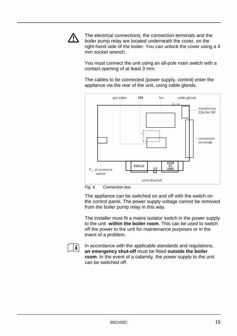
Fig. 4 Connection box
The electrical connections, the connection terminals and the
to the unit within the boiler room. This can be used to switch
In accordance with the applicable standards and regulations,
boiler pump relay are located underneath the cover, on theright-hand side of the boiler. You can unlock the cover using a 4mm socket wrench.
You must connect the unit using an all-pole main switch with acontact opening of at least 3 mm.
The cables to be connected (power supply, control) enter theappliance via the rear of the unit, using cable glands.
The appliance can be switched on and off with the switch onthe control panel. The power supply voltage cannot be removedfrom the boiler pump relay in this way.
The installer must fit a mains isolator switch in the power supply
off the power to the unit for maintenance purposes or in theevent of a problem.
an emergency shut-off must be fitted outside the boilerroom. In the event of a calamity, the power supply to the unitcan be switched off.
50CV02C16
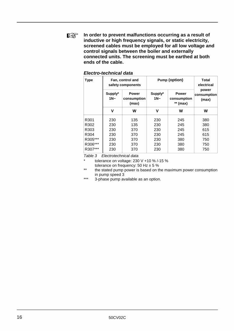
In order to prevent malfunctions occurring as a result ofinductive or high frequency signals, or static electricity,screened cables must be employed for all low voltage andcontrol signals between the boiler and externallyconnected units. The screening must be earthed at bothends of the cable.
Electro-technical dataType Fan, control and Pump (option) Total
safety components electricalpower
consumption(max)
Supply* Power Supply* Power1N~ consumption 1N~ consumption
(max) ** (max)
V W V W W
R301 230 135 230 245 380R302 230 135 230 245 380R303 230 370 230 245 615R304 230 370 230 245 615R305*** 230 370 230 380 750R306*** 230 370 230 380 750R307*** 230 370 230 380 750Table 3 Electrotechnical data* tolerance on voltage: 230 V +10 % /-15 %
tolerance on frequency: 50 Hz ± 5 %** the stated pump power is based on the maximum power consumption
in pump speed 3*** 3-phase pump available as an option.
50CV02C 17
Control and optionsThe appliances are fitted with a proportional regulation system.This can be made temperature dependent with the aid of a 0 – 10 VDC (= +2 °C – +90 °C) signal. In addition, the boilerregulating system can be extended by fitting one of the threeoptions described below:
BME optionThis is a weather-compensated regulator with the followingpossibilities:- Three on/off periods per day with three different temperatures- Night-time temperature reduction- Domestic hot water priority with time programming- Anti-legionella provision- Optimum start- Room-temperature sensor (can be switched off)- Two-wire communication bus connection- Multi-language display- External control.
E6 optionThis is a regulator with which two secondary groups can beweather-dependently controlled. In addition, domestic hot watertemperature can also be regulated. All the settings can beadjusted independently for each group. This E6 regulator canbe further extended with an optimizing controller for each group(BM). The boiler is then directly weather-dependentlycontrolled.
KKM optionThis is a boiler cascade manager permitting up to eight boilersto be switched in cascade. The KKM also has the samepossibilities as the E6 option.
Connection terminalsThe operation of the appliance can be influenced by externallygenerated signals applied to the appropriate terminals.Terminal DescriptionL1-N-E Boiler power supply; must be fused at 10 A. 8 - 9 Domestic hot water primary pump control. This
output provides a voltage (230 V) when the boiler isoperational as a result of a domestic hot water hea-ting demand.
10 - 11 Boiler enable (230 V). When these terminals areconnected the primary pump will be started and theboiler will be enabled. When there is an open circuitbetween them the boiler will be shut down. The pump will also stop after the set run on time.These terminals can be used, among other things,for setting the boilers to standby during the summer
50CV02C18
months whilst continuing to provide domestic hotwater priority.
12 Operation signal. If a fault has occurred 3 times ormore within 6 minutes, the fault code will appear inthe display with a "3" and the operation signal fallsoff (230 V, 50 Hz, 1 A ).
14 - 15 Control voltage for an external gas valve. This outputbegins to provide 230 V before the boiler starts up;the voltage ceases after the boiler shuts down. Thisoutput can be used to open hydraulic valves or tooperate boiler room ventilation.
16 - 17 Calorifier thermostat (230- V). When these terminalsare interconnected the boiler will try to provide theset flow temperature programmed for the boiler. Thisinput only functions if terminals 34 - 35 areinterconnected.
18 - 19 Interlock input (230 V). If the connection betweenthese terminals is interrupted, the boiler will bedeactivated and wait until the connection is restored(after 6 minutes or if the same fault has occurredthree times within 6 minutes, this input will lock out).
20 - 21 Lockout input (230 V). If the connection betweenthese terminals is broken the boiler will enter thefault mode. Reinstate the connection and press thereset push-button.
30 - 31 External sensor*. After a suitable sensor has beenconnected it will be automatically recognised whenthe power supply is switched on.
32 - 33 Low velocity header sensor*. This sensor canmeasure the temperature of a low velocity header.
35 - 36 Calorifier temperature sensor*. After a suitablesensor has been connected it will be automaticallyrecognised when the power supply voltage isswitched on. The terminals 34 - 35 must not beinterconnected. The purpose of this function, incomparison with the calorifier thermostat, is to makepossible a night time temperature reduction and ananti- legionella switching (only with BME, E6 orKKM).
37 - 38 External influence input (2 – 10 VDC = +10 °C – +90°C)*. At voltages below 2 V the boiler will switch to“constant supply temperature operation”.
39 - 40 External capacity output*. Only if programmed for fanspeed control. This signal provides information for acapacity display. 0 – 100 % = 0 – 10 VDC. Themaximum current is 0.5 mA.
41 - 42 SCOM bus connection (make sure to use the correctpolarity).
43 - 44 Primary boiler pump control (0 – 10 V).* In order to avoid faults caused by inductive currents, static
electricity or high frequency signals, the use of screenedcables is necessary.
50CV02C 19
5.3.3 Water connections The appliance must be installed by a recognised installer in
The boiler pump is however not a system pump
In order to limit the losses occurring in a non-operational boiler,
accordance with the applicable national and local specificationsand regulations (see Supplement). The flow and returnconnections are made at the rear of the unit.
Water connection supportsWe recommend that the supply and return pipes be properlysupported using brackets to prevent mechanically overloadingthe lines and to simplify maintenance.
The unit is a constant water flow appliance and is suitable foruse in both open vented (non-pressurised) systems and sealed(pressurised) systems provided the minimum pressurerequirements, as per table 10, are met. The unit is optionally fitted with a boiler pump which guarantees the required watercirculation through the boiler. The capacity and working head ofthe pump is sufficient to overcome both the resistance of theboiler and some resistance offered by the system.
If the resistance of the system exceeds the available workinghead, the boiler will be shut down by the flow switch. In order toprevent this happening, the length and diameter of the primarypipework between the boiler and the low velocity header mustbe chosen such that the remaining working head of the pump(see table 8) will not be exceeded.It is recommended that manually operated valves be fittedbetween the water connections and the installation.
Connect the boiler pump on the return side, making sure tokeep a distance to the flow switch of at least 5 x d.
The boiler pump (optional) can be installed horizontally orvertically.
a motorised valve is sometimes fitted in the flow or the returnpipe or a mechanical non-return valve is used for this purpose. Standby losses can be reduced even further by shutting downthe boiler via the “boiler enable” terminals. A properlydimensioned low velocity header ensures that the natural flowthrough the boiler can be neglected.
50CV02C20
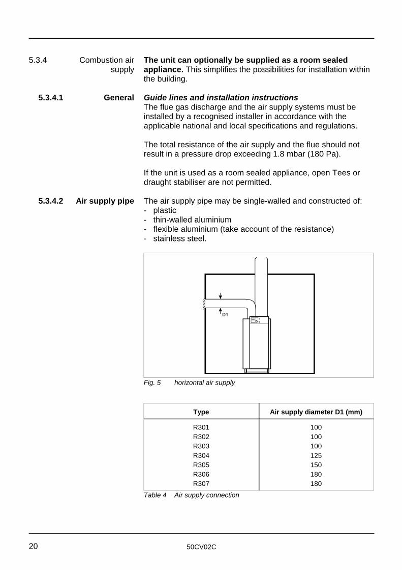
Fig. 5 horizontal air supply
5.3.4 Combustion air The unit can optionally be supplied as a room sealedsupply appliance. This simplifies the possibilities for installation within
5.3.4.1 General Guide lines and installation instructions
5.3.4.2 Air supply pipe The air supply pipe may be single-walled and constructed of:
the building.
The flue gas discharge and the air supply systems must beinstalled by a recognised installer in accordance with theapplicable national and local specifications and regulations.
The total resistance of the air supply and the flue should notresult in a pressure drop exceeding 1.8 mbar (180 Pa).
If the unit is used as a room sealed appliance, open Tees ordraught stabiliser are not permitted.
- plastic- thin-walled aluminium- flexible aluminium (take account of the resistance)- stainless steel.
Type Air supply diameter D1 (mm)
R301 100R302 100R303 100R304 125R305 150R306 180R307 180
Table 4 Air supply connection
50CV02C 21
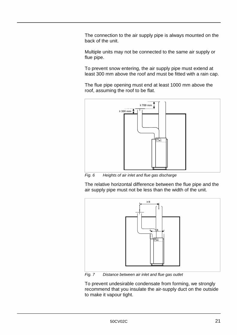
Fig. 6 Heights of air inlet and flue gas discharge
Fig. 7 Distance between air inlet and flue gas outlet
The connection to the air supply pipe is always mounted on theback of the unit.
Multiple units may not be connected to the same air supply orflue pipe.
To prevent snow entering, the air supply pipe must extend atleast 300 mm above the roof and must be fitted with a rain cap.
The flue pipe opening must end at least 1000 mm above theroof, assuming the roof to be flat.
The relative horizontal difference between the flue pipe and theair supply pipe must not be less than the width of the unit.
To prevent undesirable condensate from forming, we stronglyrecommend that you insulate the air-supply duct on the outsideto make it vapour tight.
50CV02C22
5.3.5 The Flue system
5.3.5.1 General The flue system must be installed by a recognised installer in
The condensate drain must never become blocked!
5.3.5.2 Chimney
accordance with the applicable national and local specificationsand regulations.The flue pipe connection is at the back of the appliance andhas been designed for direct connection to a corrosion resistingflue pipe.
When the boiler functions as a high capacity boiler, the highefficiency can lead to the formation of condensation in thechimney.
Direct connection to brick built stacks is not permitted becausethe combustion efficiency of the boiler is > 83 %.
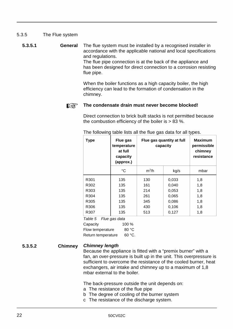
The following table lists all the flue gas data for all types.Type Flue gas Flue gas quantity at full Maximum
temperature capacity permissibleat full chimney
capacity resistance(approx.)
°C m /h kg/s mbar3
R301 135 130 0,033 1,8R302 135 161 0,040 1,8R303 135 214 0,053 1,8R304 135 261 0,065 1,8R305 135 345 0,086 1,8R306 135 430 0,106 1,8R307 135 513 0,127 1,8
Table 5 Flue gas dataCapacity 100 %Flow temperature 80 °CReturn temperature 60 °C.
Chimney lengthBecause the appliance is fitted with a “premix burner” with afan, an over-pressure is built up in the unit. This overpressure issufficient to overcome the resistance of the cooled burner, heatexchangers, air intake and chimney up to a maximum of 1,8mbar external to the boiler.
The back-pressure outside the unit depends on:a The resistance of the flue pipeb The degree of cooling of the burner systemc The resistance of the discharge system.
50CV02C 23
The degree of cooling of the flue gasses depends on:a the insulation value of the chimneyb the local ambient temperaturec the discharge system.
The flue connection diameters of the units have been chosensuch that the speed of the flue gas will always be approximately5 m/s. For the appliance there will be a maximum overpressureof approximately 1.8 mbar (180 Pa) for the flue system.
Owing to their high resistance, bends with an R/D ratio smallerthan 1 should be avoided.
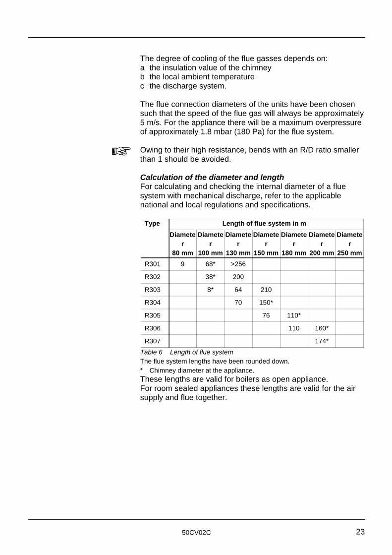
Calculation of the diameter and lengthFor calculating and checking the internal diameter of a fluesystem with mechanical discharge, refer to the applicablenational and local regulations and specifications.
Type Length of flue system in m Diamete Diamete Diamete Diamete Diamete Diamete Diamete
r r r r r r r80 mm 100 mm 130 mm 150 mm 180 mm 200 mm 250 mm
R301 9 68* >256
R302 38* 200
R303 8* 64 210
R304 70 150*
R305 76 110*
R306 110 160*
R307 174*Table 6 Length of flue systemThe flue system lengths have been rounded down.* Chimney diameter at the appliance.These lengths are valid for boilers as open appliance.For room sealed appliances these lengths are valid for the airsupply and flue together.
50CV02C24
5.3.6 Condensate discharge
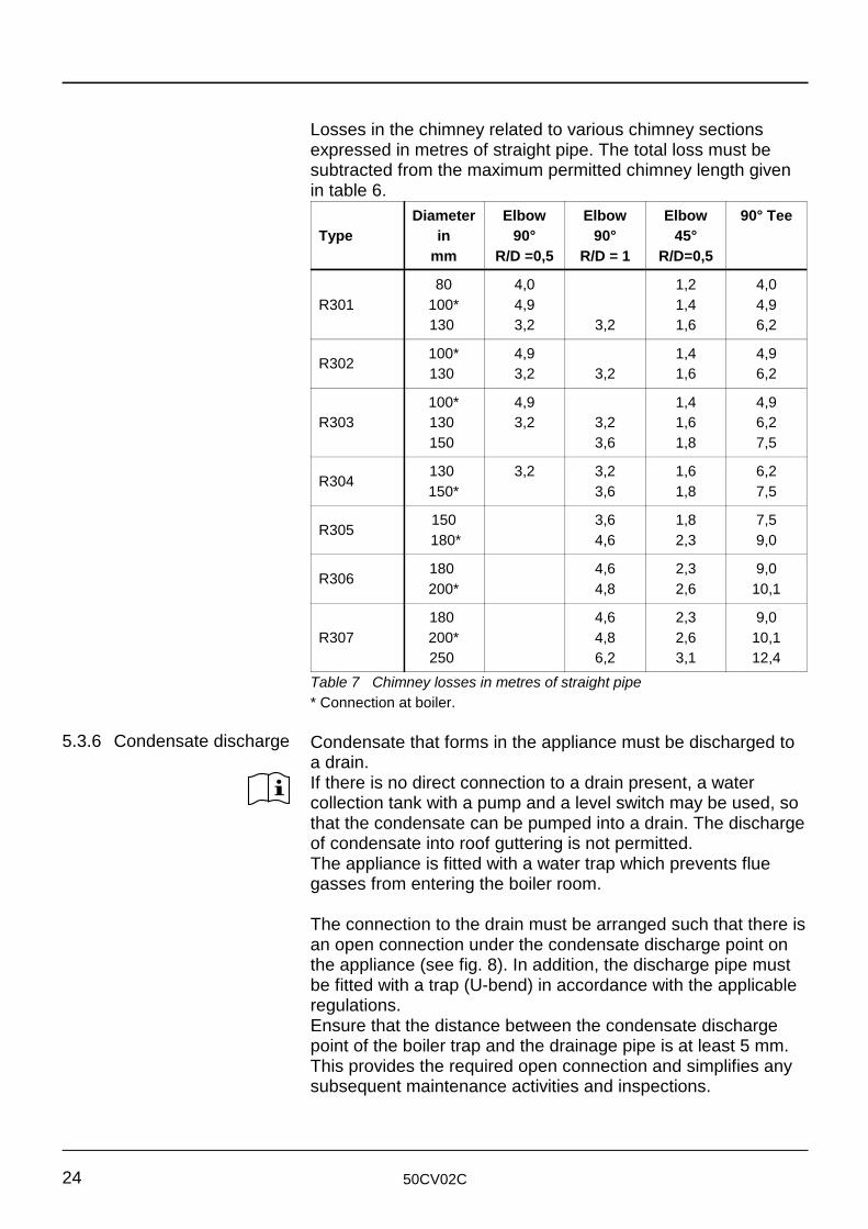
Losses in the chimney related to various chimney sectionsexpressed in metres of straight pipe. The total loss must besubtracted from the maximum permitted chimney length givenin table 6.
Type in 90° 90° 45°Diameter Elbow Elbow Elbow 90° Tee
mm R/D =0,5 R/D = 1 R/D=0,5
R301 100* 4,9 1,4 4,980 4,0 1,2 4,0
130 3,2 3,2 1,6 6,2
R302 100* 4,9 1,4 4,9130 3,2 3,2 1,6 6,2
R303 130 3,2 3,2 1,6 6,2100* 4,9 1,4 4,9
150 3,6 1,8 7,5
R304130 3,2 3,2 1,6 6,2150* 3,6 1,8 7,5
R305150 3,6 1,8 7,5
180* 4,6 2,3 9,0
R306180 4,6 2,3 9,0200* 4,8 2,6 10,1
R307 200* 4,8 2,6 10,1180 4,6 2,3 9,0
250 6,2 3,1 12,4Table 7 Chimney losses in metres of straight pipe* Connection at boiler.
Condensate that forms in the appliance must be discharged toa drain.If there is no direct connection to a drain present, a watercollection tank with a pump and a level switch may be used, sothat the condensate can be pumped into a drain. The dischargeof condensate into roof guttering is not permitted.The appliance is fitted with a water trap which prevents fluegasses from entering the boiler room.
The connection to the drain must be arranged such that there isan open connection under the condensate discharge point onthe appliance (see fig. 8). In addition, the discharge pipe mustbe fitted with a trap (U-bend) in accordance with the applicableregulations.Ensure that the distance between the condensate dischargepoint of the boiler trap and the drainage pipe is at least 5 mm.This provides the required open connection and simplifies anysubsequent maintenance activities and inspections.

50CV02C 25
Fig. 8 Condensate discharge
5.4 Hydraulic system
5.4.1 General Although it is not the intention to provide a complete handbook
5.4.2 Water flow
5.4.2.1 Flow rate and The rate of water flow through the appliance must never fallresistance below the required minimum (otherwise the water flow switch
covering the most divergent hydraulic systems, the data is moreextensive than would generally be provided in the case ofconventional central heating boilers.
The R300 unit is a low water content boiler for which the waterflow rates must be within minimum and maximum values.
Tables 8 + 10 list the required relationship between the threeparameters Q (water flow), P (pressure) and t (temperature) atmaximum capacity. Because of the high flow rate, theappliance is less sensitive to water hardness. Therefore, thewater hardness may not exceed 250 ppm with a supplytemperature of 80 °C (see 5.4.5 Water quality).
will be activated and the appliance will be shut down). The useof valves, non-return valves, systems in which severalappliances are connected to a common transport system, etc.,must not interfere with the required water circulation.
50CV02C26
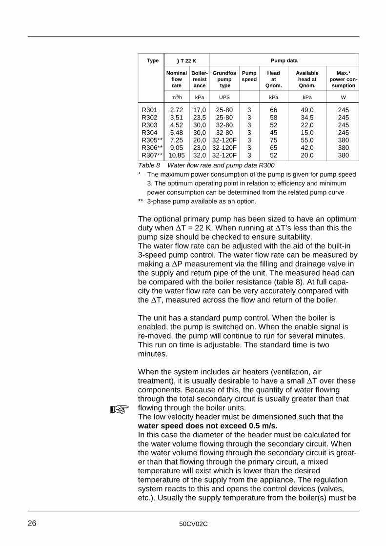
Type Pump data))))T 22 K
Nominal Boiler- Grundfos Pump Head Available Max.*flow resist pump speed at head at power con-rate ance type Qnom. Qnom. sumption
m /h kPa UPS kPa kPa W3
R301 2,72 17,0 25-80 3 66 49,0 245R302 3,51 23,5 25-80 3 58 34,5 245R303 4,52 30,0 32-80 3 52 22,0 245R304 5,48 30,0 32-80 3 45 15,0 245R305** 7,25 20,0 32-120F 3 75 55,0 380R306** 9,05 23,0 32-120F 3 65 42,0 380R307** 10,85 32,0 32-120F 3 52 20,0 380
Table 8 Water flow rate and pump data R300* The maximum power consumption of the pump is given for pump speed
3. The optimum operating point in relation to efficiency and minimumpower consumption can be determined from the related pump curve
** 3-phase pump available as an option.
The optional primary pump has been sized to have an optimumduty when ∆T = 22 K. When running at ∆T’s less than this thepump size should be checked to ensure suitability.The water flow rate can be adjusted with the aid of the built-in3-speed pump control. The water flow rate can be measured bymaking a ∆P measurement via the filling and drainage valve inthe supply and return pipe of the unit. The measured head canbe compared with the boiler resistance (table 8). At full capa-city the water flow rate can be very accurately compared withthe ∆T, measured across the flow and return of the boiler.
The unit has a standard pump control. When the boiler isenabled, the pump is switched on. When the enable signal isre-moved, the pump will continue to run for several minutes.This run on time is adjustable. The standard time is twominutes.
When the system includes air heaters (ventilation, airtreatment), it is usually desirable to have a small ∆T over thesecomponents. Because of this, the quantity of water flowingthrough the total secondary circuit is usually greater than thatflowing through the boiler units.The low velocity header must be dimensioned such that thewater speed does not exceed 0.5 m/s. In this case the diameter of the header must be calculated forthe water volume flowing through the secondary circuit. Whenthe water volume flowing through the secondary circuit is great-er than that flowing through the primary circuit, a mixedtemperature will exist which is lower than the desiredtemperature of the supply from the appliance. The regulationsystem reacts to this and opens the control devices (valves,etc.). Usually the supply temperature from the boiler(s) must be
50CV02C 27
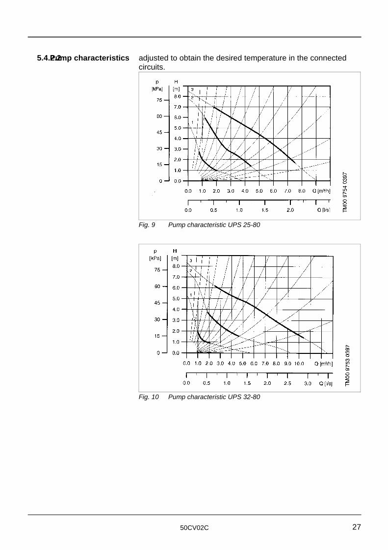
Fig. 9 Pump characteristic UPS 25-80
Fig. 10 Pump characteristic UPS 32-80
5.4.2.2Pump characteristics adjusted to obtain the desired temperature in the connectedcircuits.
50CV02C28
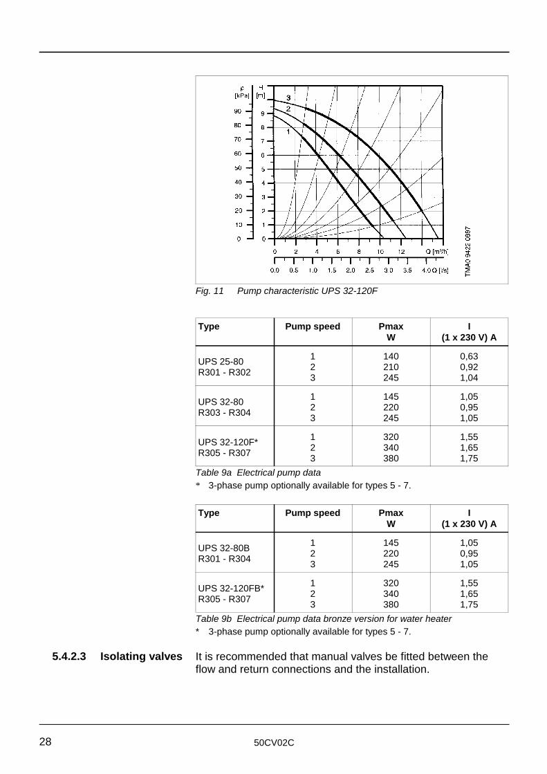
Fig. 11 Pump characteristic UPS 32-120F
5.4.2.3 Isolating valves
Type Pump speed Pmax IW (1 x 230 V) A
UPS 25-80R301 - R302
1 140 0,632 210 0,923 245 1,04
UPS 32-80R303 - R304
1 145 1,052 220 0,953 245 1,05
UPS 32-120F*R305 - R307
1 320 1,552 340 1,653 380 1,75
Table 9a Electrical pump data* 3-phase pump optionally available for types 5 - 7.
Type Pump speed Pmax IW (1 x 230 V) A
UPS 32-80BR301 - R304
1 145 1,052 220 0,953 245 1,05
UPS 32-120FB*R305 - R307
1 320 1,552 340 1,653 380 1,75
Table 9b Electrical pump data bronze version for water heater* 3-phase pump optionally available for types 5 - 7.
It is recommended that manual valves be fitted between theflow and return connections and the installation.
50CV02C 29
5.4.2.4 Valves
5.4.2.5 Water flowprotection
5.4.3 Water pressure
5.4.3.1Operating pressure
5.4.3.2 Boiler expansion
tank
5.4.3.3System expansiontank
5.4.3.4 Water pressureprotection
5.4.4 Water temperature
5.4.5 Water quality
Mechanical non-return valve can be used. This is required soas to avoid short-circuiting the appliance on the water side.
The unit is provided with water flow switch. This shuts theappliance down in the event that the flow of water through theappliance falls below the minimum required value.
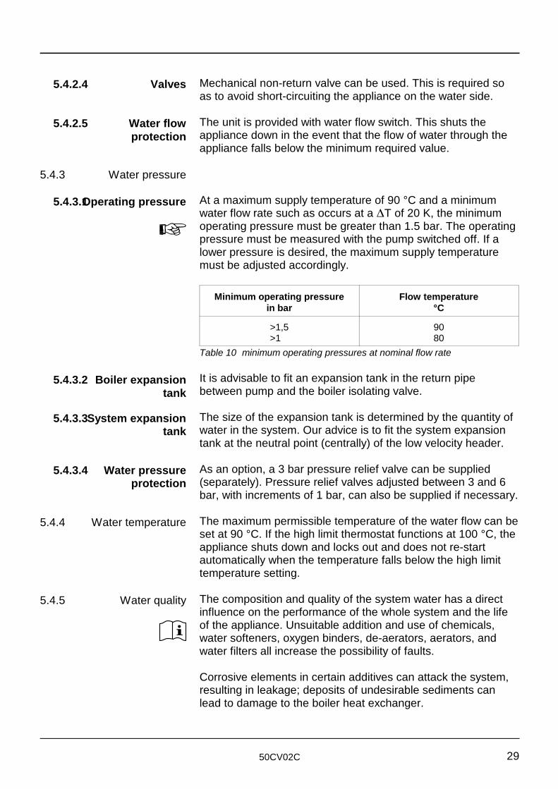
At a maximum supply temperature of 90 °C and a minimumwater flow rate such as occurs at a ∆T of 20 K, the minimumoperating pressure must be greater than 1.5 bar. The operatingpressure must be measured with the pump switched off. If alower pressure is desired, the maximum supply temperaturemust be adjusted accordingly.
Minimum operating pressure Flow temperaturein bar °C
>1,5 90>1 80
Table 10 minimum operating pressures at nominal flow rate
It is advisable to fit an expansion tank in the return pipebetween pump and the boiler isolating valve.
The size of the expansion tank is determined by the quantity of water in the system. Our advice is to fit the system expansiontank at the neutral point (centrally) of the low velocity header.
As an option, a 3 bar pressure relief valve can be supplied(separately). Pressure relief valves adjusted between 3 and 6bar, with increments of 1 bar, can also be supplied if necessary.
The maximum permissible temperature of the water flow can beset at 90 °C. If the high limit thermostat functions at 100 °C, theappliance shuts down and locks out and does not re-startautomatically when the temperature falls below the high limittemperature setting.
The composition and quality of the system water has a directinfluence on the performance of the whole system and the lifeof the appliance. Unsuitable addition and use of chemicals,water softeners, oxygen binders, de-aerators, aerators, andwater filters all increase the possibility of faults.
Corrosive elements in certain additives can attack the system,resulting in leakage; deposits of undesirable sediments canlead to damage to the boiler heat exchanger.
50CV02C30
The system must contain soft to moderately hard water
For water hardness, a distinction must be made between:a Temporary hardness
This is also referred to as carbonate hardness. Deposits areformed at higher temperatures and are easy to remove
b Permanent hardnessMinerals (for example, calcium sulphate) dissolved in thewater can be deposited as a function of very high surfacetemperatures.
In general, water hardness is expressed in mg/litre (ppm) and isgiven the following divisions:Very soft less than 50 ppmSoft approx. 50 - 160 ppmModerately hard approx. 160 - 250 ppmHard and very hard over 250 ppm.
with a water hardness not exceeding 250 ppm with asupply temperature of 80 °C and ∆∆∆∆T = 20 K.
Before the water is topped up, the hardness and the chloridecontent of the water must be determined.During the construction of larger installations, one of theappliances may be operational. New circuits may be regularlyswitched in, which must occur together with the addition offresh water. In addition, it can happen that, because of leakage,some circuits must be disconnected, repaired and re-filled. Inthese circumstances the only appliance in operation oftenfunctions at full capacity and the chance of boiler scaleformation is present. For this reason the make-up water mustbe softened. To ensure proper functioning of the appliance andthe system, the use of water softeners is recommended.
Large stationary bubbles with widely different compositions canform at “dead points” in the system (in addition to oxygen andnitrogen, hydrogen and methane have also been detected).Oxygen promotes corrosion. Corrosion products, together withother pollutants, form a sludge deposit (magnetite) which caus-es pitting under the influence of oxygen.
The use of an air separator with an automatic de-aerator isstrongly recommended. This should preferably be fitted in ahorizontal section of the return pipe to the pump. If a verticallow velocity header is employed, the air separator should befitted above the header.
ø =
Q3600
x 1,28
v
50CV02C 31
The chloride concentration must not exceed 200 mg/l. If this
5.4.6 Examples of The hydraulic systems shown are only examples. They musthydraulic systems not be employed in practice without professional analysis.
level is exceeded, the cause must be located. Compare thechloride concentration of the additional water with that of thesystem water. If this concentration is higher, this indicatesevaporation if no chloride containing materials have beenadded. If chloride is present in high concentrations the waterwill be more aggressive (due to, among other things, incorrectlyregeneration of the water softener). The system must then beflushed out and re-filled with low chloride content water.
To reduce the effects of unnecessary wear and blockagesresulting from any pollution present we advise the use of a filtersystem with a mesh opening of 100 microns. Always fit this inthe return pipe of the secondary part of the system.In order to guarantee a well functioning system and a long life,any suspended and corrosion producing particles must beremoved with the aid of a well chosen and fitted filter system.The analysis of system water and the cleaning of filters mustform part of the periodic inspection procedure.
If there is an intention to add chemicals (such as inhibitors) tothe water, contact must be made with the supplier. The suppliercan provide advice on filter systems and other requirements.
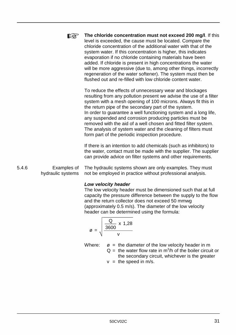
Low velocity headerThe low velocity header must be dimensioned such that at fullcapacity the pressure difference between the supply to the flowand the return collector does not exceed 50 mmwg(approximately 0.5 m/s). The diameter of the low velocityheader can be determined using the formula:
Where: ø = the diameter of the low velocity header in mQ = the water flow rate in m /h of the boiler circuit or3
the secondary circuit, whichever is the greaterv = the speed in m/s.
50CV02C32
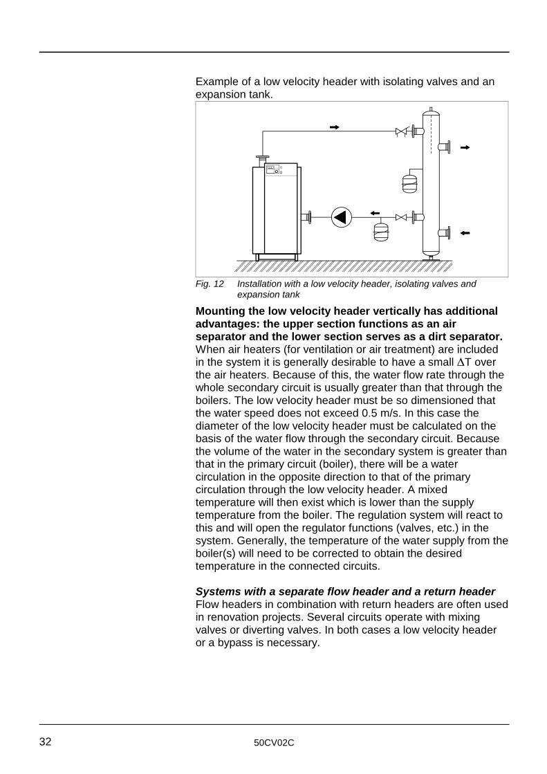
Fig. 12 Installation with a low velocity header, isolating valves andexpansion tank
Example of a low velocity header with isolating valves and anexpansion tank.
Mounting the low velocity header vertically has additionaladvantages: the upper section functions as an airseparator and the lower section serves as a dirt separator.When air heaters (for ventilation or air treatment) are includedin the system it is generally desirable to have a small ∆T overthe air heaters. Because of this, the water flow rate through thewhole secondary circuit is usually greater than that through theboilers. The low velocity header must be so dimensioned thatthe water speed does not exceed 0.5 m/s. In this case thediameter of the low velocity header must be calculated on thebasis of the water flow through the secondary circuit. Becausethe volume of the water in the secondary system is greater thanthat in the primary circuit (boiler), there will be a watercirculation in the opposite direction to that of the primarycirculation through the low velocity header. A mixedtemperature will then exist which is lower than the supplytemperature from the boiler. The regulation system will react tothis and will open the regulator functions (valves, etc.) in thesystem. Generally, the temperature of the water supply from theboiler(s) will need to be corrected to obtain the desiredtemperature in the connected circuits.
Systems with a separate flow header and a return headerFlow headers in combination with return headers are often usedin renovation projects. Several circuits operate with mixingvalves or diverting valves. In both cases a low velocity headeror a bypass is necessary.
50CV02C 33
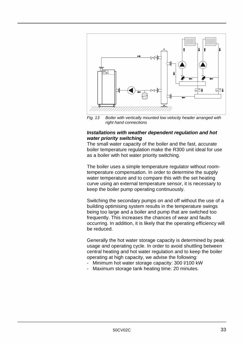
Fig. 13 Boiler with vertically mounted low velocity header arranged withright hand connections
Installations with weather dependent regulation and hotwater priority switchingThe small water capacity of the boiler and the fast, accurateboiler temperature regulation make the R300 unit ideal for useas a boiler with hot water priority switching.
The boiler uses a simple temperature regulator without room-temperature compensation. In order to determine the supplywater temperature and to compare this with the set heatingcurve using an external temperature sensor, it is necessary tokeep the boiler pump operating continuously.
Switching the secondary pumps on and off without the use of abuilding optimising system results in the temperature swingsbeing too large and a boiler and pump that are switched toofrequently. This increases the chances of wear and faultsoccurring. In addition, it is likely that the operating efficiency willbe reduced.
Generally the hot water storage capacity is determined by peakusage and operating cycle. In order to avoid shuttling betweencentral heating and hot water regulation and to keep the boileroperating at high capacity, we advise the following:- Minimum hot water storage capacity: 300 l/100 kW- Maximum storage tank heating time: 20 minutes.
50CV02C34
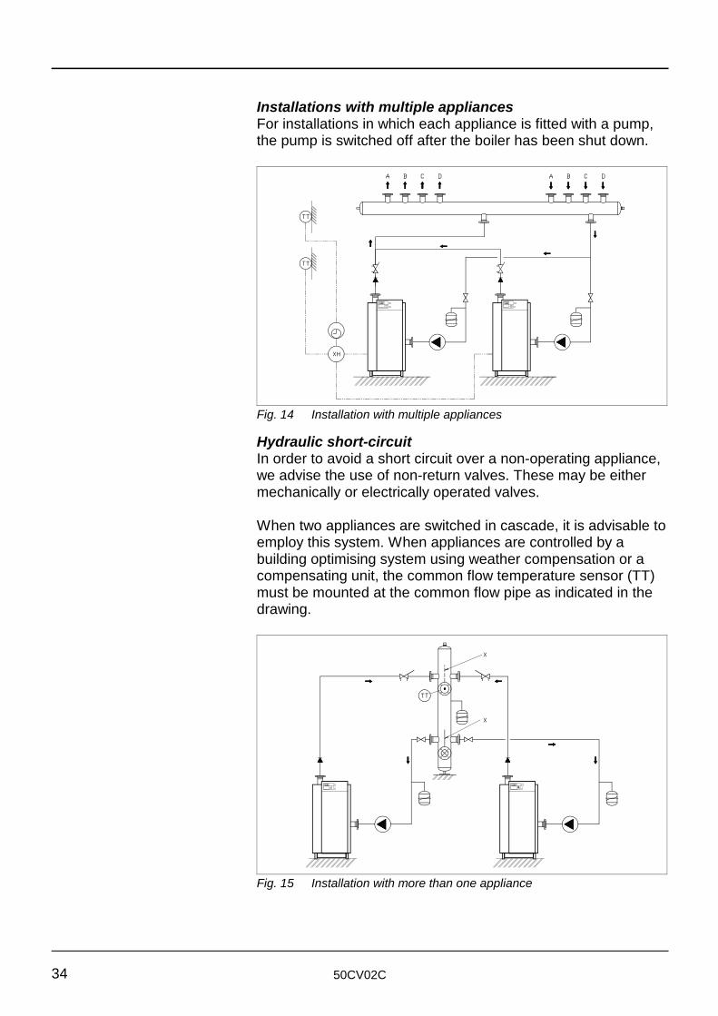
Fig. 14 Installation with multiple appliances
Fig. 15 Installation with more than one appliance
Installations with multiple appliancesFor installations in which each appliance is fitted with a pump,the pump is switched off after the boiler has been shut down.
Hydraulic short-circuit In order to avoid a short circuit over a non-operating appliance,we advise the use of non-return valves. These may be eithermechanically or electrically operated valves.
When two appliances are switched in cascade, it is advisable toemploy this system. When appliances are controlled by abuilding optimising system using weather compensation or acompensating unit, the common flow temperature sensor (TT)must be mounted at the common flow pipe as indicated in thedrawing.
50CV02C 35
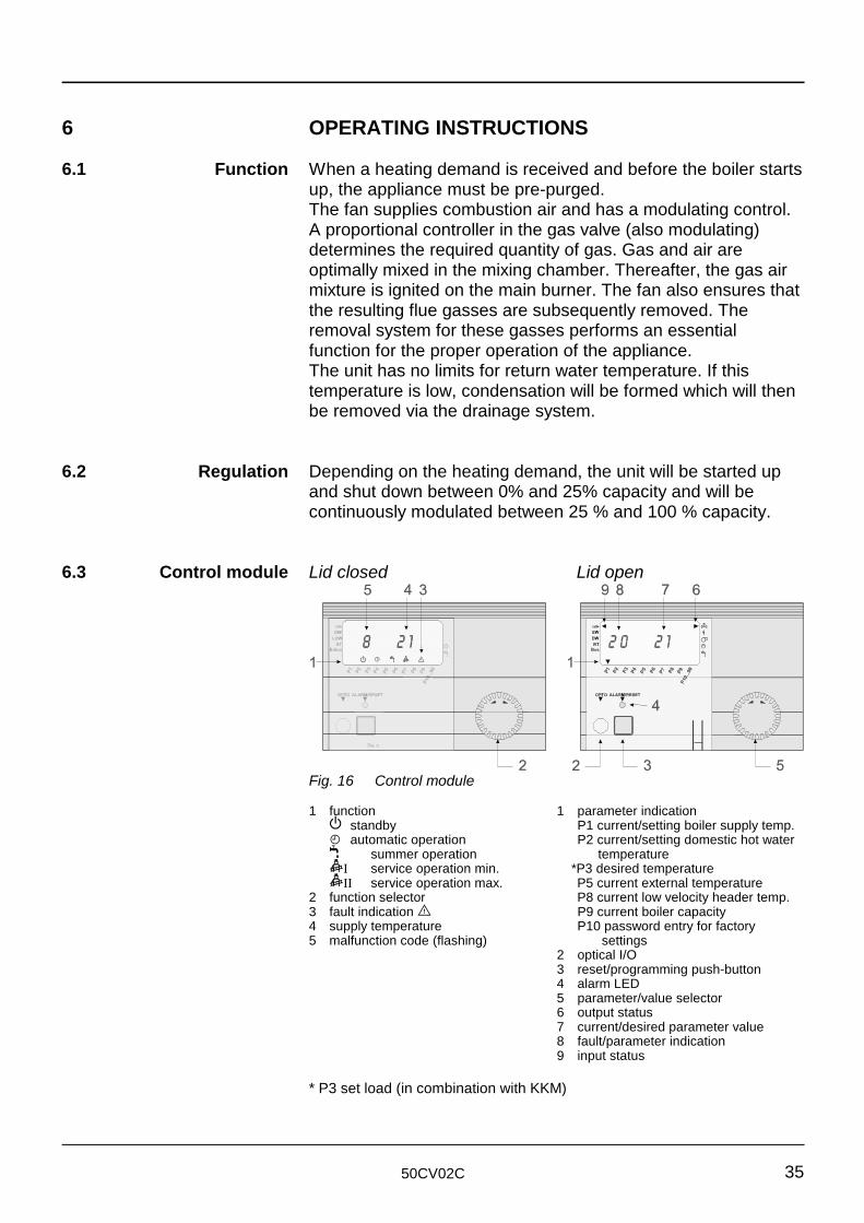
Fig. 16 Control module
6 OPERATING INSTRUCTIONS
6.1 Function When a heating demand is received and before the boiler starts
6.2 Regulation Depending on the heating demand, the unit will be started up
6.3 Control module Lid closed Lid open
up, the appliance must be pre-purged.The fan supplies combustion air and has a modulating control.A proportional controller in the gas valve (also modulating)determines the required quantity of gas. Gas and air areoptimally mixed in the mixing chamber. Thereafter, the gas airmixture is ignited on the main burner. The fan also ensures thatthe resulting flue gasses are subsequently removed. Theremoval system for these gasses performs an essentialfunction for the proper operation of the appliance. The unit has no limits for return water temperature. If thistemperature is low, condensation will be formed which will thenbe removed via the drainage system.
and shut down between 0% and 25% capacity and will becontinuously modulated between 25 % and 100 % capacity.
1 function 1 parameter indicationi standby P1 current/setting boiler supply temp.F automatic operation P2 current/setting domestic hot water
F summer operation temperaturejI service operation min. *P3 desired temperaturejII service operation max. P5 current external temperature
2 function selector P8 current low velocity header temp.3 fault indication E P9 current boiler capacity4 supply temperature P10 password entry for factory5 malfunction code (flashing) settings
2 optical I/O3 reset/programming push-button4 alarm LED5 parameter/value selector6 output status7 current/desired parameter value8 fault/parameter indication9 input status
* P3 set load (in combination with KKM)
50CV02C36
Operating mode (cover closed)With the cover closed and by using the rotational switch (pos.No. 2) clockwise or anti-clockwise the boilers’ operating modecan be set.
The operating modes are:-K standby the boiler switched off but frost protection is
activeF automatic the boiler can operate in heating or direct
hot water modeF summer mode the boiler will only react to a direct hot water
demandjI service, low capacity the boiler will run at low capacityjII service, high capacity the boiler will run at full capacity.
Information modeWith the cover open and by turning the rotational switch (Pos.No 5) clockwise or anti-clockwise it is possible to read outcertain information from the boiler management unit.
There are 10 possibilities. An arrow at the bottom of the LCDdisplay will indicate which parameter has been selected. Thefollowing parameters are readable:-
ParameterP1 actual/setting flow temperatureP2 actual/setting direct hot water temperature (if used)P3 setpoint temperature (* P3 set load in comb. with KKM)P5 actual outside temperature (if used)P8 temperature at the low velocity header (if used)P9 actual boiler capacityP10 only for trained service engineers.
Summary of input and output indications (cover open)Input indications: -H Flame Ionisation detectedSW Water flow switch in operating positionDW APS in operating positionRT Boiler enabled by BMS Bus Data-bus detected.
Output indications: -Power to Main Gas Valve
Power to IgnitorControl signal to fan
Z Power to Primary Boiler PumpF Power to Primary DHW Pump.
50CV02C 37
Setting the flow temperature for Central Heating (coveropen)Only applicable to boilers without weather compensated flowtemperature or a 0 - 10 Volt control signal.
N.B. Only applicable if outside temperature compensation or a0 - 10 V signal is not used.
- Open the lid (the arrow at the bottom of the LCD displayindicates parameter P1)
- Push the Reset/Programming key (pos.3), the LED will light, turn the rotary switch (pos.5) until the desired water flowtemperature has been reached
- Push the Reset/Programming key, the LED will go out- Close the cover.
Setting the flow temperature for Domestic Hot Water (coveropen)N.B. Only applicable if the Direct Hot Water function is usedwith the BM-E expansion module.
- Open the lid- Turn the rotational switch (pos.5) clockwise until the arrow at
the bottom of the LCD display indicates parameter P2- Push the Reset/Programming key (pos.3), the LED will light,
turn the rotary switch until the desired Domestic Hot Waterflow temperature has been reached
- Push the Reset/Programming key, the LED will go out- Close the cover.
50CV02C38
6.4 Fault indications A fault always results in a flashing E symbol and a fault codeappearing in the display. When a fault occurs, the cause mustalways be found and corrected before the related protectivefunction is reset. If a fault has occurred 3 times or more within 6minutes, the fault code will appear in the display with a "3"above it. If the supplementary fault code "3" is present for 6minutes or if a deactivating fault is detected for more than 6minutes, a fault signal (terminals 12 - 13) will follow. The boilercan be nevertheless in operation.
1 The high limit thermostat has operated. The boilertemperature has exceeded 100 °C. Press the reset button.
2/3 The interlocking input has been interrupted. Correct theexternal error and press reset.
4 Flame signal fault. No flame detected at burner start. Onerestart possible. Correct fault and press reset.
5 Flames go out during operation. If this fault occurs 3 timeswithin 6 minutes, the fault will be lock out. Correct the faultand press reset.
6 Temperature protection has operated. The boiler temp. hasexceeded the setting. Press reset.
7 The lockout input has been interrupted. Correct the externalfault and press reset.
11 Error in flame signal. A flame has been detected duringstart-up. Correct the fault and press reset.
12 Flow temperature sensor is faulty. Correct fault.13 Wiring of the CXE/EM extension module is defective.
Correct fault.14 Hot water temp. sensor is defective. Correct fault.15 External temp. sensor is defective. Correct fault.18 Header temp. sensor is defective. Correct fault.20 Error in the control of gas valve 1. After burner has stopped
a flame has been detected for a period of 5 seconds. Thisin spite of the fact that valve has been sent a close signal.Correct fault.
21 Error in the control of gas valve 2. After burner has stoppeda flame has been detected for a period of 5 seconds. Thisin spite of the fact that valve has been sent a close signal.Correct fault.
22 Air flow too low. The air pressure switch has not operated.Press reset.
23 The air pressure switch has not switched off. Press reset.24 The fan does not reach the set speed during pre-ventilating.
Correct fault.25 The fan does not reach the set speed during ignition.
Correct fault.26 The fan does not come to a standstill. Correct fault.27 The air pressure switch switched off during operation.30 CRC error in EEprom data group “Boiler”. Press reset.
50CV02C 39
6.5 Start-up 1 Open the gas valve
6.6 Shut-down The unit can be shut down in three different ways:
6.7 Warnings The unit must be installed by a recognised installer. The
31 CRC error in EEprom data group “Burner”. Press reset.32 Fault in 24 V circuit. Correct fault.40 Error detected in the position of the flow switch. Correct
fault.X.Y. An internal fault has been detected during the self-test.
Press reset.
2 Switch on the appliance using the on/off switch on thecontrol panel
3 Select the function “automatic operation q” using thefunction selector (see also the operating instructions on theboiler).
A The boiler continues to supply domestic hot water. Selectthe F function with the function switch
B The boiler is not operating and will only start up forautomatic frost protection. Select the i function using thefunction selector
C Shut down the boiler:1 Switch off the boiler using the on/off switch on the
control panel2 Close the gas valve.
operating instructions must be strictly observed.
If the source of the fault cannot be found, the serviceorganisation must be contacted. Never repair the applianceyourself.
The condensate drain may never be modified or closed off.When a boiler is completely shut down in the winter period,there is a danger of freezing. Drain the water out with the aid ofthe filling/drainage valve. The user must never make anymodifications to the appliance or the discharge system.
Annual checking and good maintenance are necessary in orderto guarantee optimum performance.
50CV02C40
7 COMMISSIONING
7.1 General Commissioning must be carried out by skilled personnel.
7.2 Commissioning Water and the hydraulic system
This may never exceed 200 mg/l. If this concentration is
Failure to observe this condition will invalidate the guarantee.
Take a sample of the water from the filling/drainage valve onthe boiler and a sample of the make-up water. Determine thewater hardness using the titration method. The water hardnessmust be less than 250 ppm. If the measured hardness is toohigh, the water must be softened.Determine the concentration of chloride in the system water.
exceeded, the system must be flushed through and re-filledwith low chloride water.Check the pressure of the system water. This must have atleast the minimum value given in table 10 (Operatingpressures).Check that there is a by-pass or a low velocity header fitted inthe hydraulic system. This is a requirement.
Check and bleed the pumpSwitch on the power supply to the boiler at the on/off switch andcheck the direction of rotation of the boiler pump after removingthe end cap from the pump motor housing. Before the appliance is started up, any air present must be bledout of the pump by removing the end cap from the pump motorhousing. This must be repeated after the appliance has been inoperation for a short time.
Check the chimneyCheck the chimney. Ensure that the connection between theappliance and the chimney is such that gasses cannot escape.If necessary, apply an appropriate sealing tape.
Bleed the gas pipeworkOpen the gas valve. Check that the gas piping is gas-tight.Remove any air between the gas valve and the appliance.
50CV02C 41
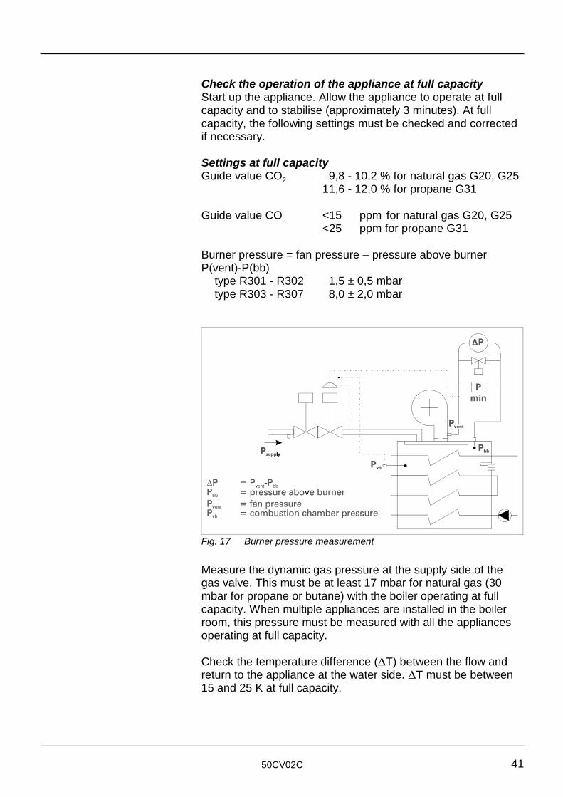
Fig. 17 Burner pressure measurement
Check the operation of the appliance at full capacityStart up the appliance. Allow the appliance to operate at fullcapacity and to stabilise (approximately 3 minutes). At fullcapacity, the following settings must be checked and correctedif necessary.
Settings at full capacityGuide value CO 9,8 - 10,2 % for natural gas G20, G252
11,6 - 12,0 % for propane G31
Guide value CO <15 ppm for natural gas G20, G25<25 ppm for propane G31
Burner pressure = fan pressure – pressure above burner P(vent)-P(bb)
type R301 - R302 1,5 ± 0,5 mbartype R303 - R307 8,0 ± 2,0 mbar
Measure the dynamic gas pressure at the supply side of thegas valve. This must be at least 17 mbar for natural gas (30mbar for propane or butane) with the boiler operating at fullcapacity. When multiple appliances are installed in the boilerroom, this pressure must be measured with all the appliancesoperating at full capacity.
Check the temperature difference (∆T) between the flow andreturn to the appliance at the water side. ∆T must be between15 and 25 K at full capacity.
50CV02C42
Check the appliance at minimum capacityAdjust the appliance to operate at minimum capacity. Atminimum capacity the following settings must be checked andcorrected if necessary:
Settings at minimum capacityGuide value CO 9,0 - 9,4 % for natural gas G20, G252
10,8 - 11,2 % for propane G31
Guide value CO <15 ppm for natural gas G20, G25<25 ppm for propane G31
Setting air pressure switchtype 3 - 7 0,5 ± 0,05 mbar
Burner pressure = fan pressure – pressure above burnerP(vent)-P(bb)
type 1 - 2 0,1 ± 0,05 mbartype 3 - 7 0,7 ± 0,2 mbar
Adjusting the gas valve R301 - R302An adjusting screw is located at the rear of the boiler which canbe used to adjust the gas volume (CO value).2 Run the boiler at full load and check the CO value. Adjust if2necessary using the adjusting screw.
Adjusting the gas valve R303 - R307If the CO values at minimum and/or full load appear to be2incorrect, you can adjust these using the V and N adjustingscrews on the gas valve.Procedure: Run the boiler at full load (100%) and check theCO value. Adjust, if necessary, using the V adjusting screw.2Then, run the boiler at minimum load and check the CO value2again. Adjust, if necessary, using the N adjusting screw.
Adjusting the air-pressure switch R301 and R302In this example, the air-pressure switch is set at 80 % of the fanspeed when pre-ventilating.Pre-ventilating takes place at 80 % of the max. speed (P9). Theair-pressure switch is set to 0.8 x 80 = 64 turn/min. The actual switching moment can be read on the display.
Checking the air-pressure switch R303 - R307Check the function ∆P pressure switch by carefully placing aminboard (for example, a piece of strong cardboard) in front of thesupply opening to the fan and slowly slide the board so as toclose off the opening until the boiler shuts down.
50CV02C 43
If the appliance is checked in the manner indicated, andcorrected as necessary, the following pressures, at fullcapacity, must be recorded for reference on the commissioningreport note:PventPbbP -P (measure separately!)vent bbPvh∆T.
50CV02C44
8 MAINTENANCE
8.1 Safety During maintenance activities, always wear suitable clothing
8.2 General In order to ensure continued good and safe operation of the
8.3 Procedure a) Disconnect the power supply
and shoes. Consider your own safety, particularly in respect ofjewellery and loose clothing.
appliance, this must be inspected at least once per year.
The following activities must be carried out (for an extensivedescription of these activities, see 8.3):- Renew the ignition and ionisation electrodes- Clean the air inlet damper (option)- Clean the fan blades- Clean the condensate receptacle- Clean the condensate trap and the drainage pipe from the
appliance- Inspect all pressure measurement pipes and nipples- After removing the panels from the left hand side of the
appliance, ignition and burning can be observed via a sightglass
- Test the unit at the flue gas side for CO and CO and correct2these at both full and minimum capacity if necessary
- Check all the safety functions, and make any necessaryadjustments
- Measure the water temperature difference ∆T as a measureof the flow rate
- Check the water pressure- Check the water quality: hardness and chloride content- Record all data- Clean the outside of all the panels and ensure that these all
have a smart appearance.
b) Close the gas supply valve
- The ignition and ionisation electrodes are fitted at the rear ofthe appliance
- Remove the spark plug caps from the ignition and ionisationelectrodes and inspect them for possible damage, such asindications of burning or pollution (renew the spark plug capsif damaged).
50CV02C 45
8.4 Cleaning the burner The burner and the heat exchangers can be cleaned internallyand heat exchangers with suitable media. For advice concerning suitable media,
8.5 Cleaning the filter/ In order to clean the filter/screen in the gas combination block,screen in the gas this must first be removed.
combination block
8.6 Ionisation In order to carry out an ionisation measurement, a micro-measurement ammeter with a measuring range of 0 - 200 µA DC must be
8.7 Service For service and maintenance the service department of your
In order to carry out the following activities, the panels must firstbe removed.- In order to clean the air inlet damper this must first be
removed. Clean it with a vacuum cleaner- For appliances installed in a dusty environment, the fan
blades may become dirty. This will result in the air supplybeing reduced and the fan becoming unbalanced. Clean thefan blades with a brush. All loose dirt can be removed in thisway
- A trap is fitted under the condensate plate. Unscrew the trapand clean it
- Inspect all the pressure measurement pipes. Ensure thatthese are securely fastened and tighten the connection nutsif necessary
- Inspect the screws in the measuring nipples; renew themeasuring nipples if they have become damaged
- In order to measure gas and air pressures and to performmeasurements at the flue gas side, calibrated test equipmentmust be employed
- All test data must be recorded on the applicable test forms.
consult the service department of your supplier.
connected in the ionisation circuit. In this way the ionisationprotection function can be checked. The nominal ionisationcurrent is between 10 and 25 µA. The minimum ionisation current is 2.8 µA.
supplier is always available.
STOKVIS ENERGY SYSTEMS96 R WALTON ROAD, EAST MOLESEYSURREY KT8 0DLTel.: 08707 707 747Fax: 08707 707 767
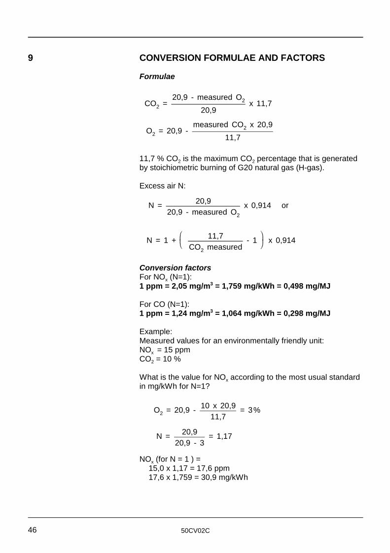
CO2 =20,9 - measured O2
20,9x 11,7
O2 = 20,9 -measured CO2 x 20,9
11,7
N = 20,920,9 - measured O2
x 0,914 or
N = 1 + 11,7CO2 measured
- 1 x 0,914
O2 = 20,9 - 10 x 20,911,7
= 3%
N = 20,920,9 - 3
= 1,17
50CV02C46
9 CONVERSION FORMULAE AND FACTORS
Formulae
11,7 % CO is the maximum CO percentage that is generated2 2by stoichiometric burning of G20 natural gas (H-gas).
Excess air N:
Conversion factorsFor NO (N=1):x1 ppm = 2,05 mg/m = 1,759 mg/kWh = 0,498 mg/MJ3
For CO (N=1):1 ppm = 1,24 mg/m = 1,064 mg/kWh = 0,298 mg/MJ3
Example:Measured values for an environmentally friendly unit:NO = 15 ppmx CO = 10 %2
What is the value for NO according to the most usual standardxin mg/kWh for N=1?
NO (for N = 1 ) =x15,0 x 1,17 = 17,6 ppm17,6 x 1,759 = 30,9 mg/kWh
ηb = 90 - 0,339CO2
+ 0,008 x ∆T
ηo = 100 - 0,377CO2
+ 0,009 x ∆T
ηb = 90 - 0,339CO2
+ 0,008 x ∆T + A (7,5 + 0,006 ∆T)
50CV02C 47
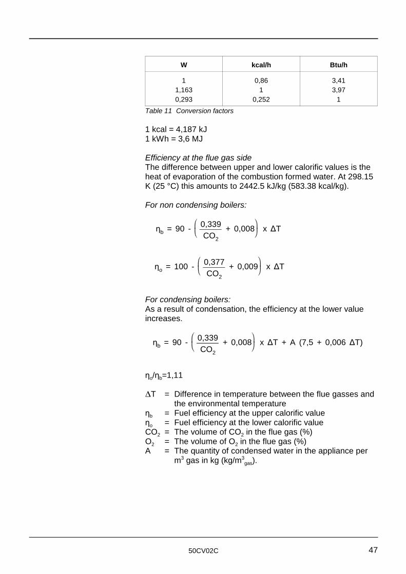
W kcal/h Btu/h
1 0,86 3,411,163 1 3,970,293 0,252 1
Table 11 Conversion factors
1 kcal = 4,187 kJ1 kWh = 3,6 MJ
Efficiency at the flue gas sideThe difference between upper and lower calorific values is theheat of evaporation of the combustion formed water. At 298.15K (25 °C) this amounts to 2442.5 kJ/kg (583.38 kcal/kg).
For non condensing boilers:
For condensing boilers:As a result of condensation, the efficiency at the lower valueincreases.
η /η =1,11o b
∆T = Difference in temperature between the flue gasses andthe environmental temperature
η = Fuel efficiency at the upper calorific valuebη = Fuel efficiency at the lower calorific valueoCO = The volume of CO in the flue gas (%)2 2O = The volume of O in the flue gas (%)2 2A = The quantity of condensed water in the appliance per
m gas in kg (kg/m ).3 3gas
50CV02C48
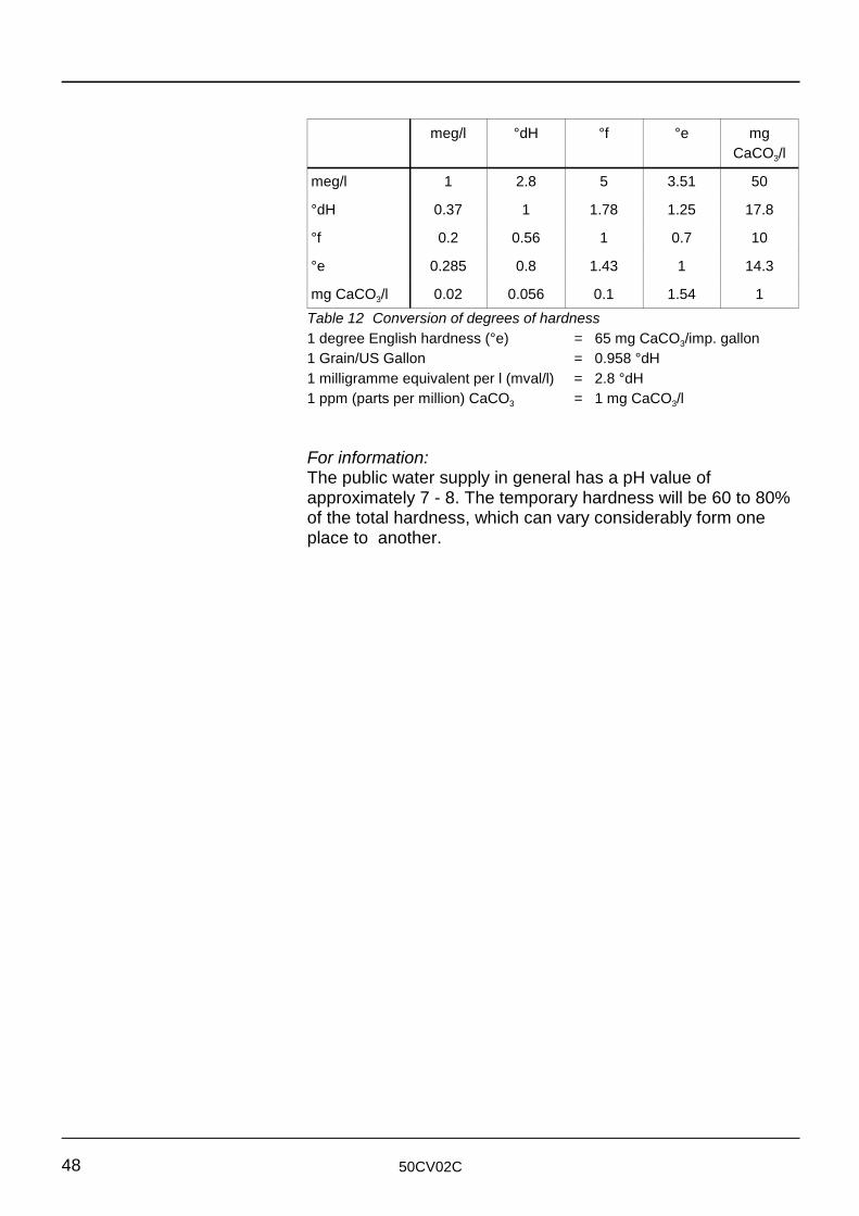
meg/l °dH °f °e mgCaCO /l3
meg/l 1 2.8 5 3.51 50
°dH 0.37 1 1.78 1.25 17.8
°f 0.2 0.56 1 0.7 10
°e 0.285 0.8 1.43 1 14.3
mg CaCO /l 0.02 0.056 0.1 1.54 13
Table 12 Conversion of degrees of hardness1 degree English hardness (°e) = 65 mg CaCO /imp. gallon3
1 Grain/US Gallon = 0.958 °dH1 milligramme equivalent per l (mval/l) = 2.8 °dH1 ppm (parts per million) CaCO = 1 mg CaCO /l3 3
For information:The public water supply in general has a pH value ofapproximately 7 - 8. The temporary hardness will be 60 to 80%of the total hardness, which can vary considerably form oneplace to another.

50CV02C 49
ECONOFLAME R300 SUPPLEMENT FOR UNITS FITTED WITH
HONEYWELL CVI MAIN GAS VALVE (DOC730/50CV02C)
STOKVIS ENERGY SYSTEMS 96R WALTON ROAD EAST MOLESEY SURREY KT8 0DL TEL: 020 8783 3050 / 08707 707 747 FAX: 020 8783 3051 / 08707 707 767 E-MAIL: [email protected] WEBSITE: www.stokvisboilers.com
50CV02B&C DOC730/50CV02C 011003

Edition 50CV02C, 15-03-2004
©2004 Rendamax B.V.All rights reserved.No part of this publication may be reproduced, stored in aretrieval system, or transmitted in any form or by any means, electronic, me-chanical, photocopying, recording or otherwise, without the prior permission in writing of Rendamax B.V..
We aim to achieve continuous improvement in our products. Therefore, specifi cations are subject to change without prior notice.
Due to changes the product can deviate from the information specifi ed in this document. Therefore Rendamax B.V. rejects any responsi-bility for the differences between the product delivered and the information mentioned in this document.
Doc730/50CVo2C
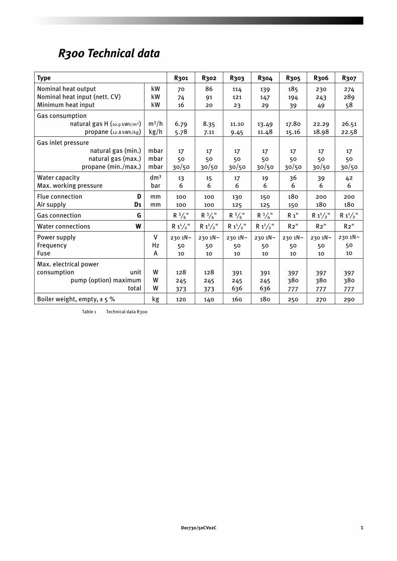
Doc730/50CVo2C 1
R300 Technical data
Type R301 R302 R303 R304 R305 R306 R307
Nominal heat output Nominal heat input (nett. CV)Minimum heat input
kWkWkW
707416
869120
11412123
13914729
18519439
23024349
27428958
Gas consumption natural gas H (10.9 kWh/m3) propane (12.8 kWh/kg)
m3/hkg/h
6.795.78
8.357.11
11.109.45
13.4911.48
17.8015.16
22.2918.98
26.5122.58
Gas inlet pressure natural gas (min.) natural gas (max.) propane (min./max.)
mbarmbarmbar
1750
30/50
1750
30/50
1750
30/50
1750
30/50
1750
30/50
1750
30/50
1750
30/50
Water capacityMax. working pressure
dm3 bar
136
156
176
196
366
396
426
Flue connection DAir supply D1
mmmm
100100
100100
130125
150125
180150
200180
200180
Gas connection G R 3⁄4" R 3⁄4" R 3⁄4" R 3⁄4" R 1" R 11⁄2" R 11⁄2"
Water connections W R 11⁄2" R 11⁄2" R 11⁄2" R 11⁄2" R2" R2" R2"
Power supplyFrequencyFuse
VHzA
230 1N~5010
230 1N~5010
230 1N~5010
230 1N~5010
230 1N~5010
230 1N~5010
230 1N~5010
Max. electrical power consumption unit pump (option) maximum total
WWW
128245373
128245373
391245636
391245636
397380777
397380777
397380777
Boiler weight, empty, ± 5 % kg 120 140 160 180 250 270 290
Table 1 Technical data R300
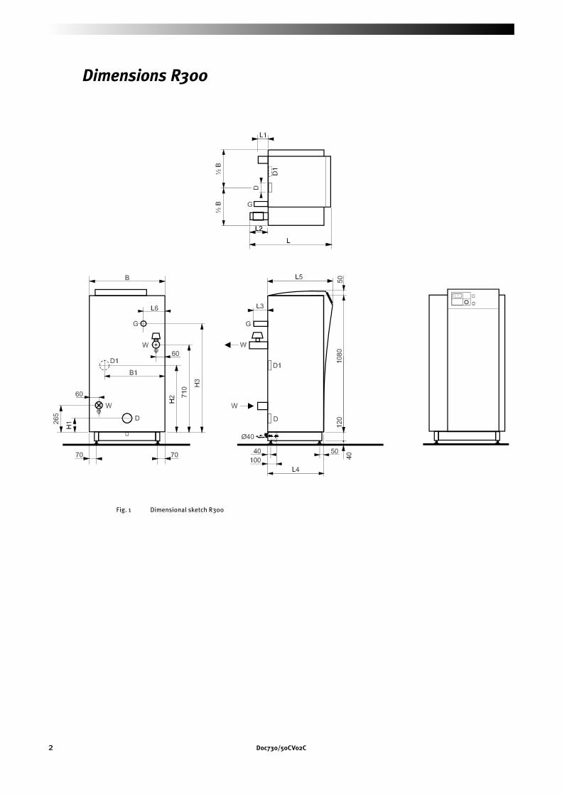
2 Doc730/50CVo2C
Dimensions R300
Fig. 1 Dimensional sketch R300
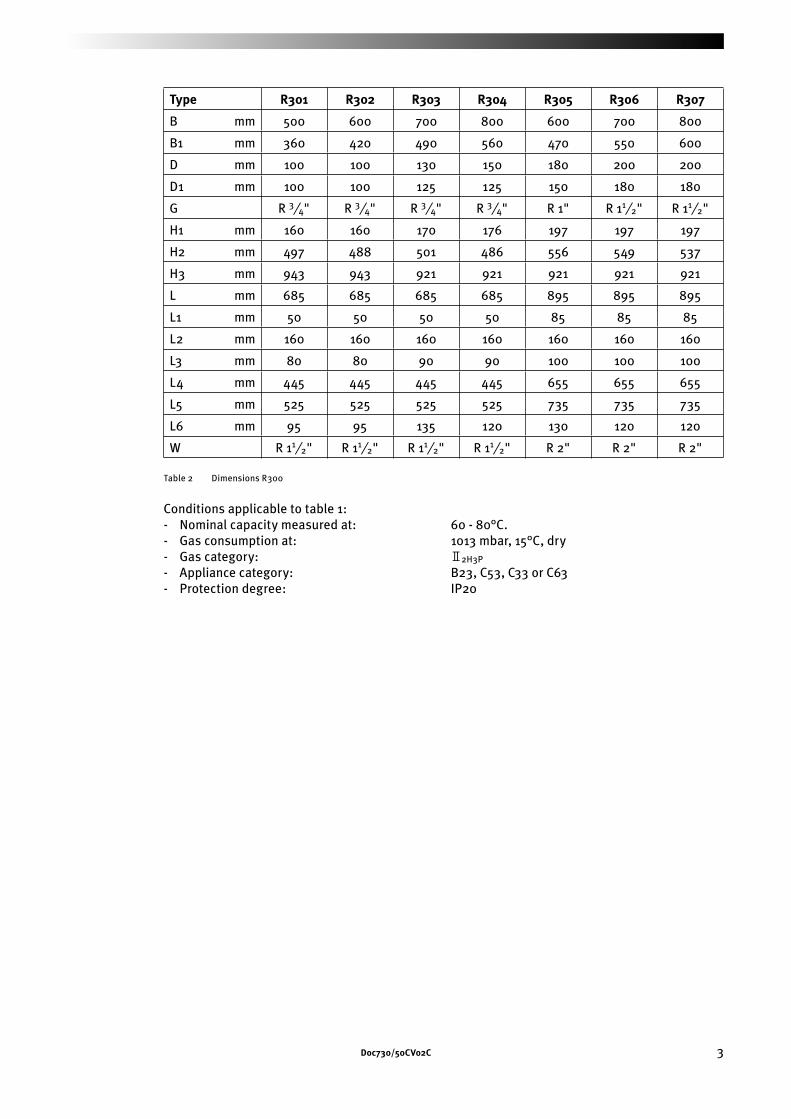
Doc730/50CVo2C 3
Type R301 R302 R303 R304 R305 R306 R307
B mm 500 600 700 800 600 700 800
B1 mm 360 420 490 560 470 550 600
D mm 100 100 130 150 180 200 200
D1 mm 100 100 125 125 150 180 180
G R 3⁄4" R 3⁄4" R 3⁄4" R 3⁄4" R 1" R 11⁄2" R 11⁄2"
H1 mm 160 160 170 176 197 197 197
H2 mm 497 488 501 486 556 549 537
H3 mm 943 943 921 921 921 921 921
L mm 685 685 685 685 895 895 895
L1 mm 50 50 50 50 85 85 85
L2 mm 160 160 160 160 160 160 160
L3 mm 80 80 90 90 100 100 100
L4 mm 445 445 445 445 655 655 655
L5 mm 525 525 525 525 735 735 735
L6 mm 95 95 135 120 130 120 120
W R 11⁄2" R 11⁄2" R 11⁄2" R 11⁄2" R 2" R 2" R 2"
Table 2 Dimensions R300
Conditions applicable to table 1:- Nominal capacity measured at: 60 - 80°C.- Gas consumption at: 1013 mbar, 15°C, dry- Gas category: 22H3P
- Appliance category: B23, C53, C33 or C63- Protection degree: IP20
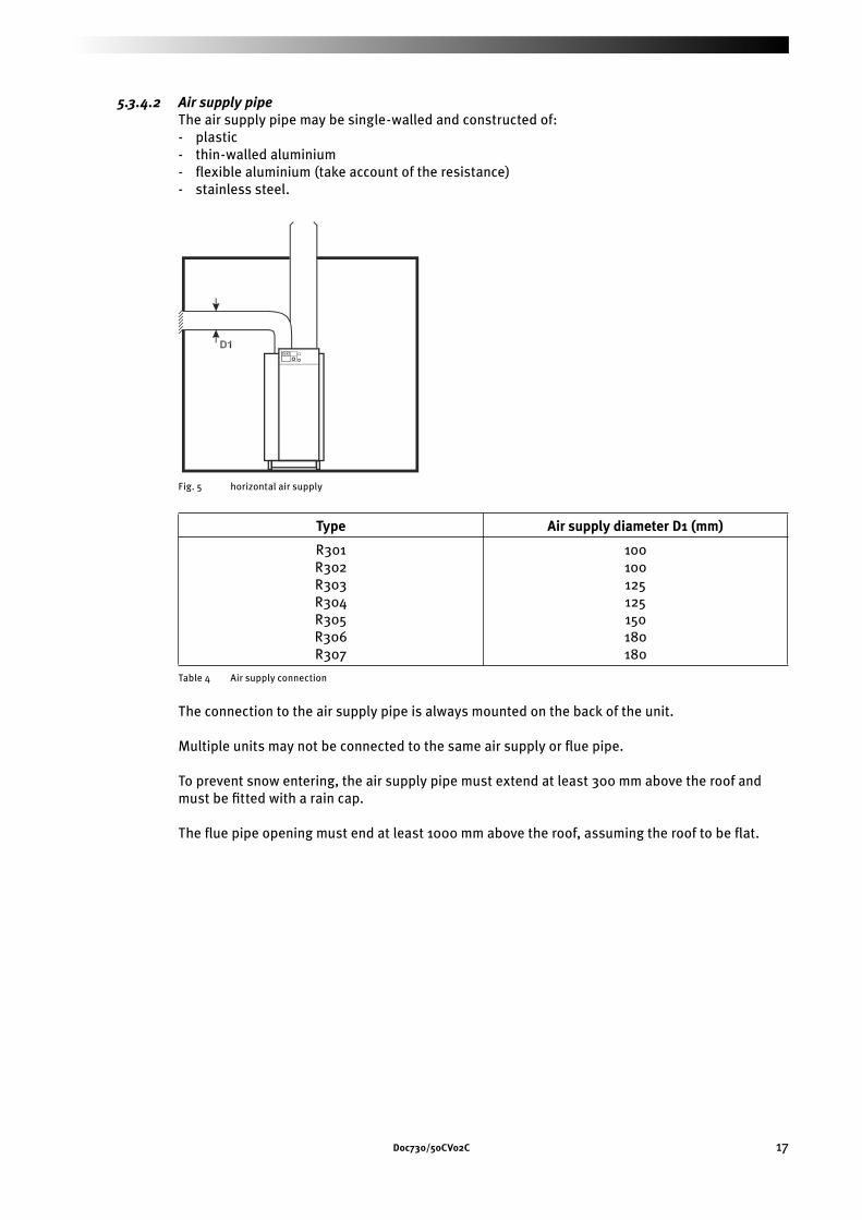
Doc730/50CVo2C 17
5.3.4.2 Air supply pipeThe air supply pipe may be single-walled and constructed of:- plastic- thin-walled aluminium- fl exible aluminium (take account of the resistance)- stainless steel.
Fig. 5 horizontal air supply
Type Air supply diameter D1 (mm)
R301R302R303R304R305R306R307
100100125125150180180
Table 4 Air supply connection
The connection to the air supply pipe is always mounted on the back of the unit.
Multiple units may not be connected to the same air supply or fl ue pipe.
To prevent snow entering, the air supply pipe must extend at least 300 mm above the roof and must be fi tted with a rain cap.
The fl ue pipe opening must end at least 1000 mm above the roof, assuming the roof to be fl at.
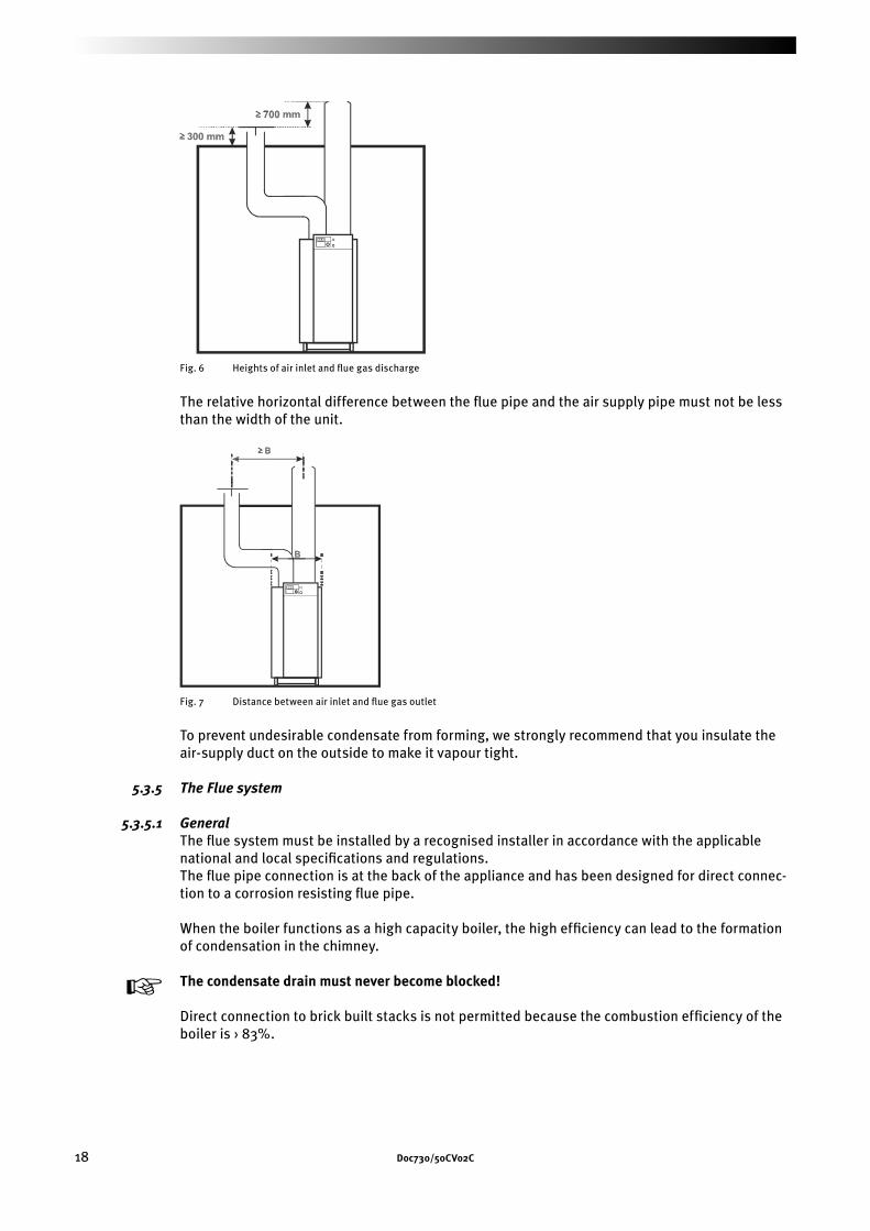
18 Doc730/50CVo2C
Fig. 6 Heights of air inlet and fl ue gas discharge
The relative horizontal difference between the fl ue pipe and the air supply pipe must not be less than the width of the unit.
Fig. 7 Distance between air inlet and fl ue gas outlet
To prevent undesirable condensate from forming, we strongly recommend that you insulate the air-supply duct on the outside to make it vapour tight.
5.3.5 The Flue system
5.3.5.1 GeneralThe fl ue system must be installed by a recognised installer in accordance with the applicable national and local specifi cations and regulations.The fl ue pipe connection is at the back of the appliance and has been designed for direct connec-tion to a corrosion resisting fl ue pipe.
When the boiler functions as a high capacity boiler, the high effi ciency can lead to the formation of condensation in the chimney.
y The condensate drain must never become blocked!
Direct connection to brick built stacks is not permitted because the combustion effi ciency of the boiler is › 83%.
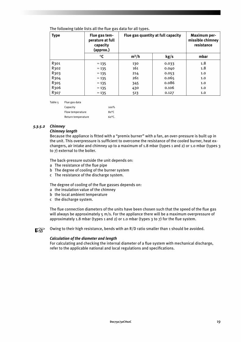
Doc730/50CVo2C 19
The following table lists all the fl ue gas data for all types.
Type Flue gas tem-perature at full
capacity(approx.)
Flue gas quantity at full capacity Maximum per-missible chimney
resistance
°C m3/h kg/s mbar
R301R302R303R304R305R306R307
≈ 135≈ 135≈ 135≈ 135≈ 135≈ 135≈ 135
130161214261345430513
0.0330.0400.0530.0650.0860.1060.127
1.81.81.01.01.01.01.0
Table 5 Flue gas data
Capacity 100%
Flow temperature 80°C
Return temperature 60°C.
5.3.5.2 ChimneyChimney lengthBecause the appliance is fi tted with a “premix burner” with a fan, an over-pressure is built up in the unit. This overpressure is suffi cient to overcome the resistance of the cooled burner, heat ex-changers, air intake and chimney up to a maximum of 1.8 mbar (types 1 and 2) or 1.0 mbar (types 3 to 7) external to the boiler.
The back-pressure outside the unit depends on:a The resistance of the fl ue pipeb The degree of cooling of the burner systemc The resistance of the discharge system.
The degree of cooling of the fl ue gasses depends on:a the insulation value of the chimneyb the local ambient temperaturec the discharge system.
The fl ue connection diameters of the units have been chosen such that the speed of the fl ue gas will always be approximately 5 m/s. For the appliance there will be a maximum overpressure of approximately 1.8 mbar (types 1 and 2) or 1.0 mbar (types 3 to 7) for the fl ue system.
y Owing to their high resistance, bends with an R/D ratio smaller than 1 should be avoided.
Calculation of the diameter and lengthFor calculating and checking the internal diameter of a fl ue system with mechanical discharge, refer to the applicable national and local regulations and specifi cations.
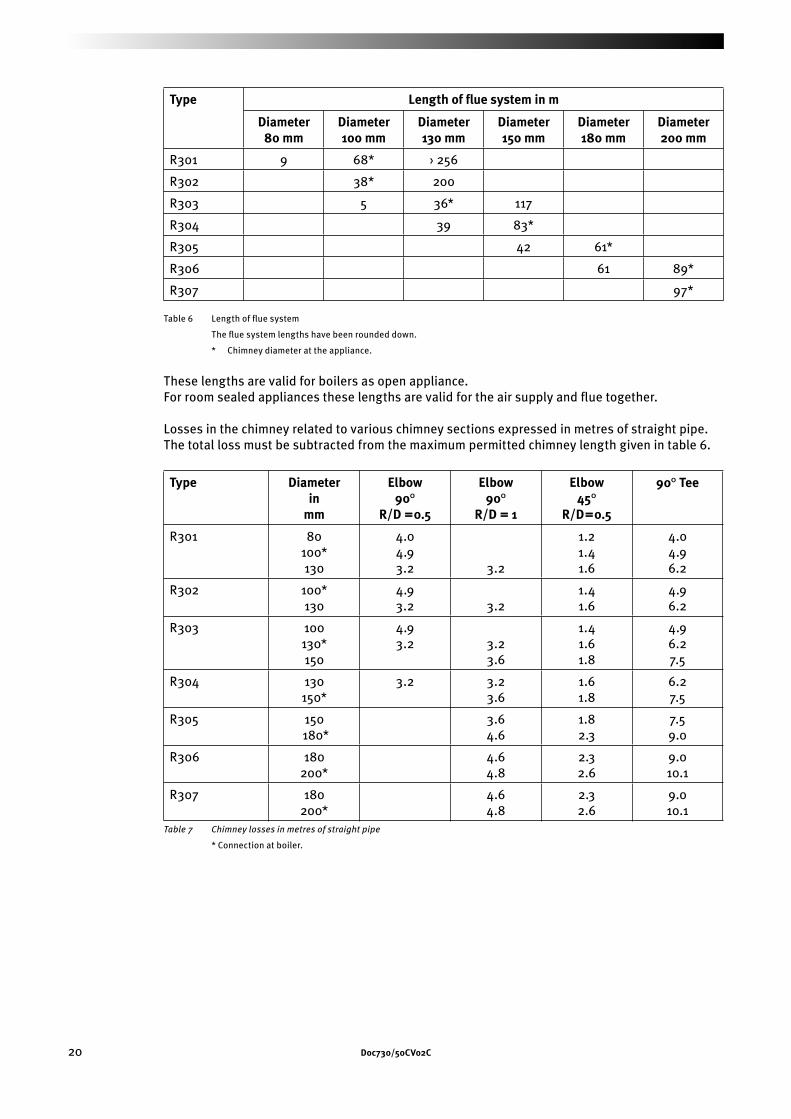
20 Doc730/50CVo2C
Type Length of fl ue system in m
Diameter80 mm
Diameter100 mm
Diameter130 mm
Diameter150 mm
Diameter180 mm
Diameter200 mm
R301 9 68* › 256
R302 38* 200
R303 5 36* 117
R304 39 83*
R305 42 61*
R306 61 89*
R307 97*
Table 6 Length of fl ue system
The fl ue system lengths have been rounded down.
* Chimney diameter at the appliance.
These lengths are valid for boilers as open appliance.For room sealed appliances these lengths are valid for the air supply and fl ue together.
Losses in the chimney related to various chimney sections expressed in metres of straight pipe. The total loss must be subtracted from the maximum permitted chimney length given in table 6.
Type Diameterin
mm
Elbow90°
R/D =0.5
Elbow90°
R/D = 1
Elbow45°
R/D=0.5
90° Tee
R301 80100*130
4.04.93.2 3.2
1.21.41.6
4.04.96.2
R302 100*130
4.93.2 3.2
1.41.6
4.96.2
R303 100130*150
4.93.2 3.2
3.6
1.41.61.8
4.96.27.5
R304 130 150*
3.2 3.23.6
1.61.8
6.27.5
R305 150 180*
3.64.6
1.82.3
7.59.0
R306 180 200*
4.64.8
2.32.6
9.010.1
R307 180 200*
4.64.8
2.32.6
9.010.1
Table 7 Chimney losses in metres of straight pipe
* Connection at boiler.
Doc730/50CVo2C 33
7 Commissioning
7.1 General
Commissioning must be carried out by skilled personnel. Failure to observe this condition will invalidate the guarantee.
7.2 Commissioning Water and the hydraulic systemTake a sample of the water from the fi lling/drainage valve on the boiler and a sample of the make-up water. Determine the water hardness using the titration method. The water hardness must be less than 250 ppm. If the measured hardness is too high, the water must be softened.
y Determine the concentration of chloride in the system water. This may never exceed 200 mg/l. If this concentration is exceeded, the system must be fl ushed through and re-fi lled with low chlo-ride water.Check the pressure of the system water. This must have at least the minimum value given in table 10 (Operating pressures).Check that there is a by-pass or a low velocity header fi tted in the hydraulic system. This is a requirement.
Check and bleed the pumpSwitch on the power supply to the boiler at the on/off switch and check the direction of rotation of the boiler pump after removing the end cap from the pump motor housing. If the direction of rota-tion is incorrect, two of the three phase connections must be swapped (only 400 V).Before the appliance is started up, any air present must be bled out of the pump by removing the end cap from the pump motor housing. This must be repeated after the appliance has been in operation for a short time.
Check the chimneyCheck the chimney. Ensure that the connection between the appliance and the chimney is such that gasses cannot escape. If necessary, apply an appropriate sealing tape.
Bleed the gas pipeworkOpen the gas valve. Check that the gas piping is gas-tight. Remove any air between the gas valve and the appliance.
Check the operation of the appliance at full capacityStart up the appliance. Allow the appliance to operate at full capacity and to stabilise (approxi-mately 3 minutes). At full capacity, the following settings must be checked and corrected if neces-sary.
Settings at full capacityGuide value CO2 9.8 - 10.2% for natural gas G20, G25 11.6 - 12.0% for propane G31 13.6 - 14.0% for butane G30
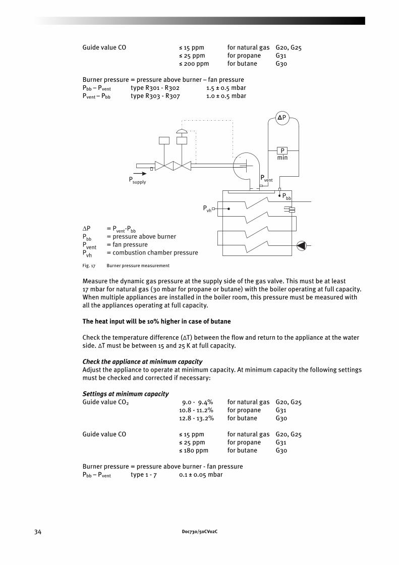
34 Doc730/50CVo2C
Guide value CO ≤ 15 ppm for natural gas G20, G25 ≤ 25 ppm for propane G31 ≤ 200 ppm for butane G30
Burner pressure = pressure above burner – fan pressurePbb – Pvent type R301 - R302 1.5 ± 0.5 mbarPvent – Pbb type R303 - R307 1.0 ± 0.5 mbar
Psupply
Pmin
Pvh
Pbb
P
∆P = Pvent-PbbPbb = pressure above burnerPvent = fan pressurePvh = combustion chamber pressure
PventventPvent
Fig. 17 Burner pressure measurement
Measure the dynamic gas pressure at the supply side of the gas valve. This must be at least 17 mbar for natural gas (30 mbar for propane or butane) with the boiler operating at full capacity. When multiple appliances are installed in the boiler room, this pressure must be measured with all the appliances operating at full capacity.
The heat input will be 10% higher in case of butane
Check the temperature difference (∆T) between the fl ow and return to the appliance at the water side. ∆T must be between 15 and 25 K at full capacity.
Check the appliance at minimum capacityAdjust the appliance to operate at minimum capacity. At minimum capacity the following settings must be checked and corrected if necessary:
Settings at minimum capacityGuide value CO2 9.0 - 9.4% for natural gas G20, G25 10.8 - 11.2% for propane G31 12.8 - 13.2% for butane G30
Guide value CO ≤ 15 ppm for natural gas G20, G25 ≤ 25 ppm for propane G31 ≤ 180 ppm for butane G30
Burner pressure = pressure above burner - fan pressurePbb – Pvent type 1 - 7 0.1 ± 0.05 mbar
Doc730/50CVo2C 35
Adjusting the gas valve R301 - R307Two screws are located at the gas valve which can be used to adjust the gas volume (CO2 value).Run the boiler at full load and check the CO2 value. Adjust if necessary using the fl at screw (types 1 and 2) or the inbus screw (types 3 to 7).Run the boiler at minimum load and check the CO2 value. Adjust if necessary using the torcx screw.
Adjusting the air-pressure switch R301 - R307The air-pressure switch is set at 80% of the fan speed when pre-ventilating.
For example: Pre-ventilating takes place at 80 rps. The air-pressure switch is set to 0.8 x 80 = 64 rps. The actual switching moment can be read on the display.
If the appliance is checked in the manner indicated, and corrected as necessary, the following pressures, at full capacity, must be recorded for reference on the commissioning report note:Pvent
Pbb
Pvent-Pbb (measure separately!)Pvh
∆T.