Embed Size (px)
Citation preview
FOR QUESTIONS REGARDING THIS SPECIFICATION DOCUMENT CONTACT:MARK KERFOOT - TECHNICAL COORDINATOR - [email protected] | 405-212-3138
BUILDBLOCK BUILDING SYSTEMS, LLC, 9705 N. BROADWAY EXT., SUITE 200, OKLAHOMA CITY, OK 73114OFFICE: 405-840-3386 | TOLL FREE: 866-222-2575 | FAX: 831-597-0792 | BUILDBLOCK.COM
TECHNICAL DATA
Footing to Wall ConnectionsOVERVIEW:
The connection between the footing and an ICF wall is very important. Too often, this connection is omitted from
the discussion about reinforcing an ICF wall. There are a number of factors that have to be taken into account.
These include the wind-loads, exposure categories, and seismic zones.
The typical connections between the footing and the ICF wall are either a keyway or dowels. Keyways are made
by setting a 2x4 into the top of the footing when it is being poured, and floating the concrete flush with the top
of the board. When this is removed, it leaves a shallow trench for the concrete from the wall to fill into, and will
prevent the wall from sliding transverse across the top of the footing.
Dowels are lengths of rebar which extend from near the bottom of the footing up into the cavity area of the forms,
and are used to control a transverse sliding movement, as well as pulling or tipping movement. A good ICF
footing will be at least 11” deep, allowing for 8” of the dowel to be embedded into the concrete (a 4 to 6-inch
“L” at the bottom further strengthens this connection). The Prescriptive Method recommends that the dowel then
should extend at least 8” from the top of the footing into the ICF wall. The minimum spacing for these is 4’o.c.
BuildBlock always recommends 40 bar diameters extending from the top of the footing.
In areas listed with 130mph+ for 3 second gusts or seismic zones the spacing of these dowels should be tightened
to no more than 18”o.c. The length of the embedment into the ICF wall should also be increased to 20” - 24”
for #4 or #5 rebar, and align these with the vertical steel. In seismic zones it is further recommended to put a 90
degree bend, 6” long at the top of the wall as well.
It is permitted to insert the vertical steel so that it is embedded into the footing by 8” as an alternative to dowels.
This is best accomplished with a monopour or at least wet-set installation, or when using knockdown forms. Other
than the monopour, this method will generally increase the block stacking time; the dowel method is preferred.
Lintels around doors and windows should also be installed with the vertical rebar on each side of the opening
having a corresponding dowel from the footing, and should maintain the minimum 40 bar diameter splice length.
This will ensure that the lintel is reinforced properly. Lintels over 2 feet in width must use rebar extending 24” into
the wall horizontally each side.
Saferooms should have dowels placed to match the vertical steel, on 12” centers, and extending into the
wall cavity 24”. This is especially important as the loads that the safe room is designed to handle require a
deeper foundation and larger footings to prevent the walls from being compromised during a storm. It is also
recommended to use an “L” on the bottom of the dowel in the footing, pushed to the bottom of the footing, and
lifted 3”.
It is important to note, that while the interior slab will prevent the wall being pushed inwards by backfill dirt, it
doesn’t control any movement toward the outside of the footing. The backfill, properly graded and compacted
will retain the walls, but having a keyway or dowels in place will eliminate any chances of movement before the
backfill is in place.
FOR QUESTIONS REGARDING THIS SPECIFICATION DOCUMENT CONTACT:MARK KERFOOT - TECHNICAL COORDINATOR - [email protected] | 405-212-3138
BUILDBLOCK BUILDING SYSTEMS, LLC, 9705 N. BROADWAY EXT., SUITE 200, OKLAHOMA CITY, OK 73114OFFICE: 405-840-3386 | TOLL FREE: 866-222-2575 | FAX: 831-597-0792 | BUILDBLOCK.COM
TECHNICAL DATA
The goal is to tie the footing to the top of the wall. By doing this, the structure has no weak points, and can
withstand a variety of forces acting on it. A wind load can be both positive and negative pressure, and can
cause forces to be exerted on the exterior or the interior. The more the structure is moving as a unit, the more
resilient it will be under load. When the parts move independently, the forces required to damage the structure
decreases dramatically, and a failure is more likely. One large advantage of concrete over wood framing, is that
the concrete can actually be monolithic for the most part, whereas, wood, being made up of individual boards
with fasteners is much more susceptible to independent movement, and will have a lower failure limit compared
to a similarly sized concrete structure. In addition, most ICF walls are thicker than the wood frames used even in
upscale construction, and thereby provide additional strength and protection.
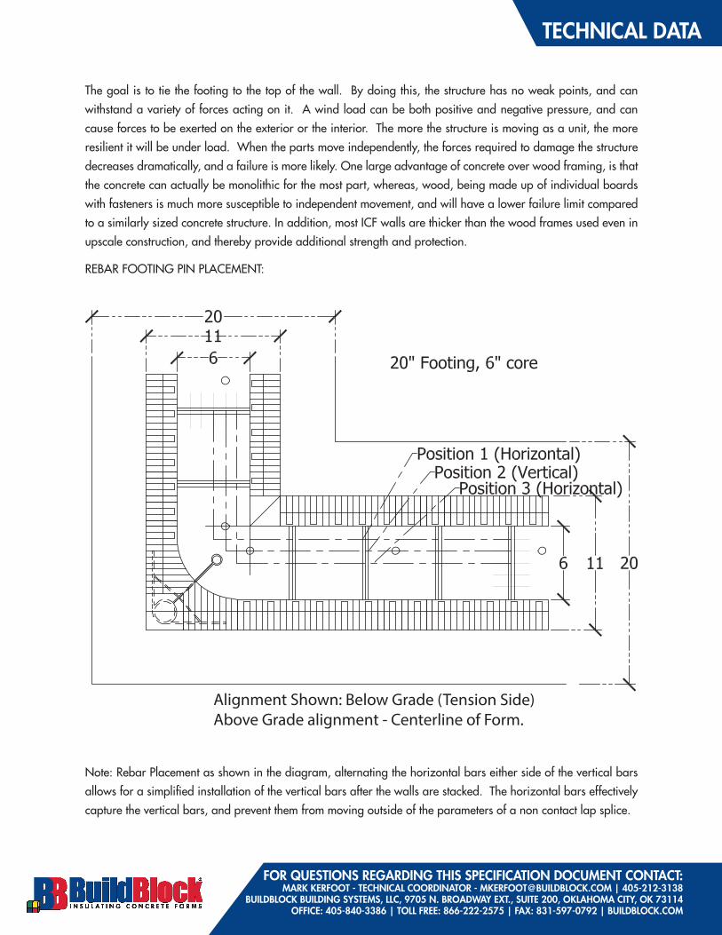
REBAR FOOTING PIN PLACEMENT:
Alignment Shown: Below Grade (Tension Side)Above Grade alignment - Centerline of Form.
Note: Rebar Placement as shown in the diagram, alternating the horizontal bars either side of the vertical bars
allows for a simplified installation of the vertical bars after the walls are stacked. The horizontal bars effectively
capture the vertical bars, and prevent them from moving outside of the parameters of a non contact lap splice.
FOR QUESTIONS REGARDING THIS SPECIFICATION DOCUMENT CONTACT:MARK KERFOOT - TECHNICAL COORDINATOR - [email protected] | 405-212-3138
BUILDBLOCK BUILDING SYSTEMS, LLC, 9705 N. BROADWAY EXT., SUITE 200, OKLAHOMA CITY, OK 73114OFFICE: 405-840-3386 | TOLL FREE: 866-222-2575 | FAX: 831-597-0792 | BUILDBLOCK.COM
TECHNICAL DATA
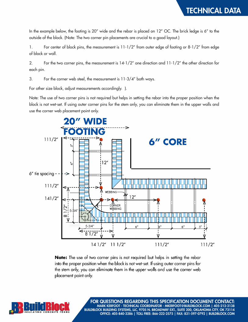
In the example below, the footing is 20” wide and the rebar is placed on 12” OC. The brick ledge is 6” to the
outside of the block. (Note: The two corner pin placements are crucial to a good layout.)
1. For center of block pins, the measurement is 11-1/2” from outer edge of footing or 8-1/2” from edge
of block or wall.
2. For the two corner pins, the measurement is 14-1/2” one direction and 11-1/2” the other direction for
each pin.
3. For the corner web steel, the measurement is 11-3/4” both ways.
For other size block, adjust measurements accordingly. ).
Note: The use of two corner pins is not required but helps in setting the rebar into the proper position when the
block is not wet-set. If using outer corner pins for the stem only, you can eliminate them in the upper walls and
use the corner web placement point only.
FOR QUESTIONS REGARDING THIS SPECIFICATION DOCUMENT CONTACT:MARK KERFOOT - TECHNICAL COORDINATOR - [email protected] | 405-212-3138
BUILDBLOCK BUILDING SYSTEMS, LLC, 9705 N. BROADWAY EXT., SUITE 200, OKLAHOMA CITY, OK 73114OFFICE: 405-840-3386 | TOLL FREE: 866-222-2575 | FAX: 831-597-0792 | BUILDBLOCK.COM
TECHNICAL DATA
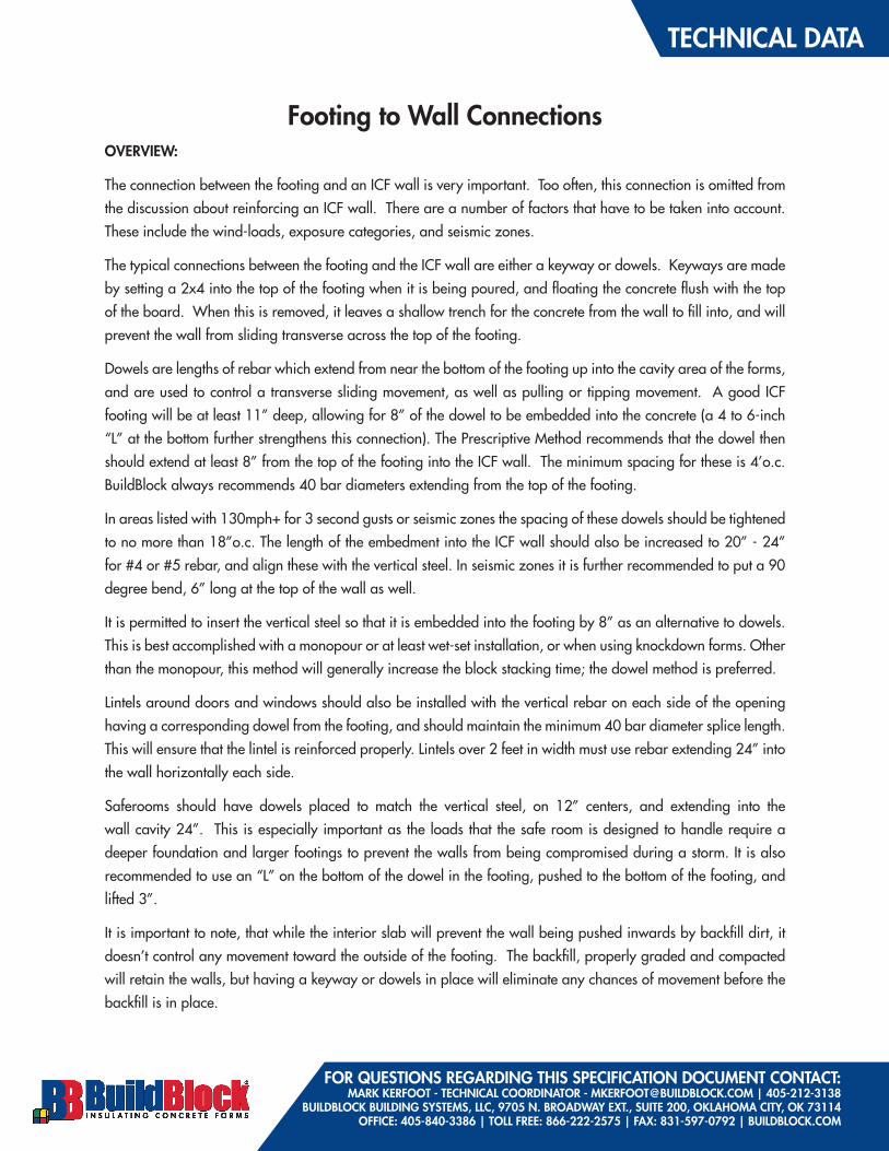
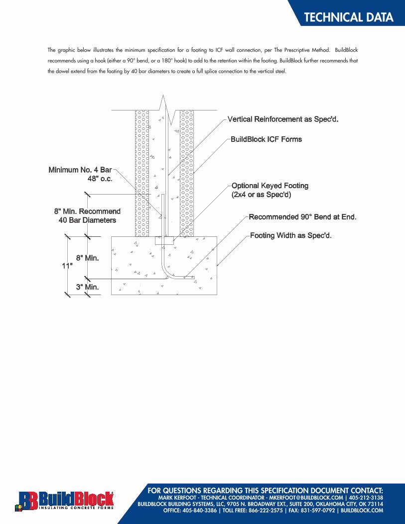
The graphic below illustrates the minimum specification for a footing to ICF wall connection, per The Prescriptive Method. BuildBlock
recommends using a hook (either a 90° bend, or a 180° hook) to add to the retention within the footing. BuildBlock further recommends that
the dowel extend from the footing by 40 bar diameters to create a full splice connection to the vertical steel.