Embed Size (px)
Citation preview

7/23/2019 10 - Design of Wall Footing
http://slidepdf.com/reader/full/10-design-of-wall-footing 1/14
1 Dr. Qaiser Iqbal (UET Peshawar)
Example 2‐Part B
Determine the required wall thickness and flexural steel at the bottom of the
stem. Use f ̕c= 4000 lb/in2 and fy = 60 k/in
2
Check shear at bottom of stem
The most critical section for shear occurs at the bottom of the stem. Since there
are no stirrups, the concrete must be sufficient to resist this shear force (i.e., we
neglect any shear resistance provided by the flexural steel).
Combining with Equation and solving produces d ≥ 6.79 in
This steel area will need to be added to the computed flexural steel area.
Evaluate flexural stresses at base of stem and design flexural steel. Using Equation
9.13

7/23/2019 10 - Design of Wall Footing
http://slidepdf.com/reader/full/10-design-of-wall-footing 2/14
2 Dr. Qaiser Iqbal (UET Peshawar)
Per Table 1 (previous lecture), the steel ratio must be no greater than 0.0214, and
preferably between about 0.0100 and 0.0143. The minimum acceptable steel area
is (0.0012)(11)(12) = 0.16 in2/ft. Therefore, the computed steel ratio is acceptable.
The total required vertical steel area, As is 0.561 + 0.143 = 0.704 in2/ft.
Use #7 bars at 9 in C/C
This steel area is sufficient to provide both flexural reinforcement and the normal
force required for shear transfer.
Design remainder of stem steel
We will use a tapered stem, with a thickness of 8 in (d = 4.5 in) at the top and 11
in (d = 7.5 in) at the bottom. The steel at the bottom of the stem will be spaced at
9 inches on center, but at some height we will cut off every other bar, leaving
steel at 18 inches on center. The maximum permissible steel spacing is 3T or 18
in, whichever is less [ACI 7 .6.5), so we cannot cut off any more bars.

7/23/2019 10 - Design of Wall Footing
http://slidepdf.com/reader/full/10-design-of-wall-footing 3/14
3 Dr. Qaiser Iqbal (UET Peshawar)
Compute ρ at the top and bottom of the stem for each steel spacing using
Equation 9.12, then use Equations 9.10 and 9.11 with φ= 0.9 to determine the
corresponding moment capacities.
Sample computation:
The factored moment and nominal moment capacities along the height of the
stem are shown in Figure 1. We use this diagram to determine the cutoff location,
which is one development length higher than the intersection of the #7 @ 18‐in
curve with the factored moment curve. In other words, this intersection is where
the wider steel spacing provides enough flexural capacity, but we need to extend
the steel one development length past this point to provide sufficient anchorage.

7/23/2019 10 - Design of Wall Footing
http://slidepdf.com/reader/full/10-design-of-wall-footing 4/14
4 Dr. Qaiser Iqbal (UET Peshawar)
Figure 1: Factored moments and flexural capacity along stem for Example 2
Per Equation 9.14 the required development length l d is:
C= clear cover
Ktr = 0 for spread footings
db = dia of the bar
Based on this information use the following steel in the stem:
7/23/2019 10 - Design of Wall Footing
http://slidepdf.com/reader/full/10-design-of-wall-footing 5/14
5 Dr. Qaiser Iqbal (UET Peshawar)
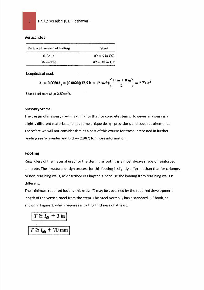
Vertical steel:
Masonry Stems
The design of masonry stems is similar to that for concrete stems. However, masonry is a
slightly different material, and has some unique design provisions and code requirements.
Therefore we will not consider that as a part of this course for those interested in further
reading see Schneider and Dickey (1987) for more information.
Footing
Regardless of the material used for the stem, the footing is almost always made of reinforced
concrete. The structural design process for this footing is slightly different than that for columns
or non‐retaining walls, as described in Chapter 9, because the loading from retaining walls is
different.
The minimum required footing thickness, T, may be governed by the required development
length of the vertical steel from the stem. This steel normally has a standard 90° hook, as
shown in Figure 2, which requires a footing thickness of at least:

7/23/2019 10 - Design of Wall Footing
http://slidepdf.com/reader/full/10-design-of-wall-footing 6/14
6 Dr. Qaiser Iqbal (UET Peshawar)
The total footing thickness, T, should be a multiple of 100 mm or 3 in, and never less than 300
mm or 12 in. The required development length for hooked bars made of grade 60 (metric grade
420) steel is [ACI 12.5]:
(top English, bottom SI)
The development length computed from Equation may be modified by the following factors
[ACI 12.5.3]1:
For standard reinforcing bars with yield strength other than 60,000 lb/in2: fy/60,000
For metric reinforcing bars with yield strength other than 420 lb/in2 :fy/420
With at least 50 mm (2 in) of cover beyond the end of the hook: 0.7
Next we design the heel extension, which is the portion of the footing beneath the backfill. The
shear and flexural stresses in this portion of the footing are due to the weight of the backfill soil
immediately above the footing plus the weight of the footing heel extension.
We ignore the bearing pressure acting along the bottom of the heel extension, which is
conservative. Thus, the heel extension is designed as a cantilever beam, as shown in Figure 2.
There is no need to develop shear and moment diagrams for the footing. Simply compute the factored shear and moment along a vertical plane immediately below the back of the wall and
use this information to check the shear capacity of the footing and to select the required
flexural reinforcement. Since the weight of the backfill is a dead load, use a load factor of 1.4.

7/23/2019 10 - Design of Wall Footing
http://slidepdf.com/reader/full/10-design-of-wall-footing 7/14
7 Dr. Qaiser Iqbal (UET Peshawar)
The flexural analysis may be performed using Equation 9.13 with the effective depth obtained
from the anchorage analysis. The steel area must satisfy the minimum and maximum steel
requirements described earlier in this section. The reinforcing steel should be placed 70 mm (3
in) from the top of the footing, and should extend to 70 mm (3 in) from the end. The shear
analysis should be based on Equations 9.2 and 9.9.
The toe extension also is designed as a cantilever beam. However, it bends in the opposite
direction (i.e., concave upward). so the flexural steel must be near the bottom. In this case, the
load is due the bearing pressure acting on the bottom of the footing and the weight of the
footing toe extension. For conservatism and simplicity, we ignore any soil that may be present
above this part of the footing. Since this bearing pressure is primarily due to the lateral earth
pressure acting on the stem, use a load factor of 1. 7.
The footing also should have longitudinal steel. A steel ratio of 0.0015 to 0.0020 is normally
appropriate. There is no need to do a longitudinal flexure analysis.
Figure 2: Loading for design of heel and toe extensions.

7/23/2019 10 - Design of Wall Footing
http://slidepdf.com/reader/full/10-design-of-wall-footing 8/14
8 Dr. Qaiser Iqbal (UET Peshawar)
Example 2‐Part C
Anchorage of vertical steel from stem
This analysis must be based on the footing concrete, which is cast separately from that in the
stem. Use fc'= 3000 lb/in2 and fy= 60,000 lb/in
2
T ≥ d + db/2 + 3 = 20.5 in
The shear analysis controls the required footing thickness, so use T = 21 in (a multiple of
3 in), d = T
‐3 in ‐ d b /2
= 21 ‐ 3 ‐ 0.5 = 17.5 in. Although this is larger than the 15 inch thickness
used in the external stability analysis, there is no need to redo that analysis.

7/23/2019 10 - Design of Wall Footing
http://slidepdf.com/reader/full/10-design-of-wall-footing 9/14
9 Dr. Qaiser Iqbal (UET Peshawar)
Heel extension‐flexure
Use #8 bars at 9 in OC (As /b = 1.05 in2/ft)
Note: This is the same spacing as the vertical stem steel, which will avoid interference problems
and facilitate tying the steel together
Longitudinal steel (per discussion in Chapter 9):
A, = 0.0018A, = (0.0018)(21 in)(8.5 ft)(l2 in/ft) = 3.86 in2
Use 14 #5 bars (As= 4.34 in2 ).

7/23/2019 10 - Design of Wall Footing
http://slidepdf.com/reader/full/10-design-of-wall-footing 10/14
10 Dr. Qaiser Iqbal (UET Peshawar)
Final design:
The final design is shown in Figure 3
Figure 3: Loading design for Example 2
DRAINAGE AND WATERPROOFING
The discussion on the effect of groundwater on loads acting on the wall demonstrated the
impact of groundwater on lateral earth pressures. Because groundwater increases earth

7/23/2019 10 - Design of Wall Footing
http://slidepdf.com/reader/full/10-design-of-wall-footing 11/14
11 Dr. Qaiser Iqbal (UET Peshawar)
pressures so dramatically, engineers provide a means of drainage whenever possible to prevent
the groundwater table from building up behind the wall. Two types of drains are commonly
used: weep holes
and perforated
pipe
drains.
Both are shown in Figure 4. It is also helpful to
include a means of intercepting water and bringing it to the drain.
.
Figure 4: Methods of draining the soil behind retaining walls: (a) weep holes; (b) perforated pipe drains
In addition to control ground water it is also important to control the migration of moisture
through the wall. This is especially important on basement walls because excessive moisture
inside basements can be both nuisance and a health hazard. Even in exterior walls, excessive
moisture migration can be an aesthetic problem. These materials may be categorized as follows
(Meyers, 1996):
• Damp‐proofing is the treatment of the wall surface to retard dampness or water penetration
under nonhydrostatic conditions. These methods are used when the wall is always above the
groundwater table, but the adjacent soil may be subject to moisture from rainfall, irrigation,
capillary rise, or other sources.

7/23/2019 10 - Design of Wall Footing
http://slidepdf.com/reader/full/10-design-of-wall-footing 12/14
12 Dr. Qaiser Iqbal (UET Peshawar)
• Waterproofing is the treatment of the wall surface to prevent passage of water under
intermittent or full hydrostatic pressure conditions. These methods are used when the wall is
occasionally or permanently below the groundwater table.
Damp‐proofing methods include:
• Thin bituminous coatings
• Thin cementitious coatings
• Acrylic latex coatings
• 6‐mil polyethylene sheets
Waterproofing methods are more expensive, and more effective. They include:
• Bituminous membranes, which consist of multiple layers of mopped‐on bituminous material
(i.e., asphalt or coal tar) with alternating layers of reinforcing fabric or felt. The final product is
similar to built‐up roofing.
• Liquid‐applied elastometric waterproofing, which consists of special chemicals applied to the
wall.
• Sheet‐applied elastometric waterproofing, which are prefabricated sheets applied to the wall.
• Cementitious waterproofing that consists of several coats of a special mortar.
• Bentonite clay panels
• Troweled on mixtures of bentonite clay and a binding agent
Alternatively, special admixtures may be used with the concrete in the wall to make it more
impervious. This method is sometimes called integral waterproofing. However, its success
depends on the absence of significant cracks, which is difficult to achieve. In addition, this
method requires special waterstops, which are plastic or rubber strips, at construction joints,
such as that between the stem and the footing.

7/23/2019 10 - Design of Wall Footing
http://slidepdf.com/reader/full/10-design-of-wall-footing 13/14
13 Dr. Qaiser Iqbal (UET Peshawar)
AVOIDANCE OF FROST HEAVE PROBLEMS
Concrete is a relatively poor insulator of heat, so retaining walls located in areas with frost
heave problems may be damaged as a result of the formation of ice lenses behind the wall. In
some cases, ice lenses have caused retaining walls to move so far out of position that they
became unusable.
Reduce frost heave problems by using all of the following preventive measures:
• Incorporate good drainage details in the design to avoid the buildup of free water behind the
wall. Deep perforated drainage pipes are usually a better choice than weep holes because they
are less likely to become blocked by frozen water.
• Use non frost‐susceptible soil for the portion of the backfill immediately behind the wall. This
zone should extend horizontally behind the wall for a distance equal to the depth of frost
penetration in that locality.
Even with these precautions, engineers working in cold climates often design retaining walls
with an additional 5 to 10 kPa (100‐200 lb/ft2) surcharge pressure acting on the ground surface.
The resulting lateral earth pressure from this surcharge results in a stronger wall design that is
better able to resist frost heave.
SUMMARY
Major Points
1. Cantilever retaining walls are the most common type of earth retaining structure.
2. Cantilever retaining walls must satisfy two major requirements: external stability (to avoid
failure in the soil) and internal stability (to avoid failure in the structure).
3. External stability requirements include the following:
• Sliding
• Overturning
• Resultant in middle third
• Bearing capacity

7/23/2019 10 - Design of Wall Footing
http://slidepdf.com/reader/full/10-design-of-wall-footing 14/14
14 Dr. Qaiser Iqbal (UET Peshawar)
• Deep‐seated shear
• Settlement
4. Internal stability requirements are satisfied by providing a structural design that satisfies the
following requirements:
• Sufficient flexural strength in the stem
• Sufficient shear strength in the stem
• Adequate connection between the stem and the footing
• Sufficient anchorage of the stem steel into the footing
• Sufficient flexural strength in the footing
5. Walls also must have proper drainage and water proofing details.
6. In regions with cold climates, walls must be protected against frost heave problems.