Embed Size (px)
Citation preview

ECE 7800: Renewable Energy SystemsTopic 14: Concentrated Solar Power
Spring 2010
© Pritpal Singh, 2010

Introduction Concentrating solar power (CSP)
technologies convert sunlight to thermal energy to run a heat engine to generate electricity.
Three approaches:1) Parabolic dish systems with
Stirling engines; 2) Linear solar trough systems;
3) Power tower concept (with heliostats)
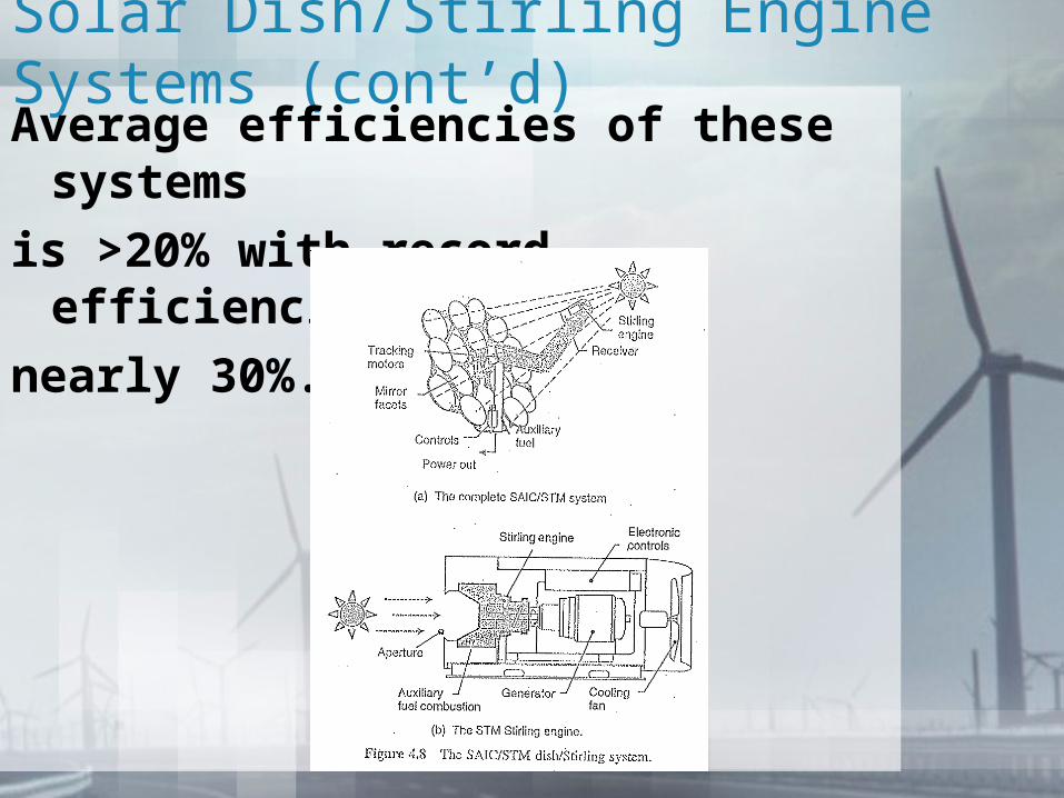
Solar Dish/Stirling Engine SystemsA set of mirrors approximate a
parabolic dish. The dish tracks the sun
and focuses the sunlight onto a thermal
receiver. The thermal receiver absorbs
the solar energy and using a heat
transfer medium, such as a bank of
tubes that contain H2 or He as the
working fluid, run a Stirling engine.
Solar Dish/Stirling Engine Systems (cont’d)Another approach is to use heat pipes
for boiling and condensing an
intermediate fluid between the receiver
and the Stirling engine. The cold side
is maintained with a water-cooled
automotive radiator-type system. This
is a closed system and consumes little
water. A fuel can be burned when
solar energy is not available to provide
continuous power output.
Solar Dish/Stirling Engine Systems (cont’d)Average efficiencies of these systems
is >20% with record efficiencies of
nearly 30%.
Solar Dish/Stirling Engine Systems (cont’d)The SAIC dish comprises 16
stretched-membrane, mirrored facets
approx. 3.2 m in diameter around a
steel ring (like a drum). The mirror is
either a thin glass mirror or a
metallized polymer. Evacuating
between the stretched membranes
allows curving of the mirrors to focus
on the receiver.
Solar Dish/Stirling Engine Systems (cont’d)The concentrated sunlight creates a
temperature of 725ºC on the Stirling
engine. The engine itself has four
cylinders, each with a double-acting
piston. Connecting rods convert the
back and forth motion of the pistons
to rotary motion for the generator.

Solar Dish/Stirling Engine Systems (cont’d)The below table shows the efficiencies of the SAIC/STM system from solar to electrical power conversion.
Land requirement with these systems is about 1MW/4 acres.

Solar Dish/Stirling Engine Systems (cont’d)
This Science Application International Corporation/STM Power Inc. 25 kW Dish-Stirling System is operating at a Salt River Project site in Phoenix, AZ. (Courtesy: Sandia National Labs)
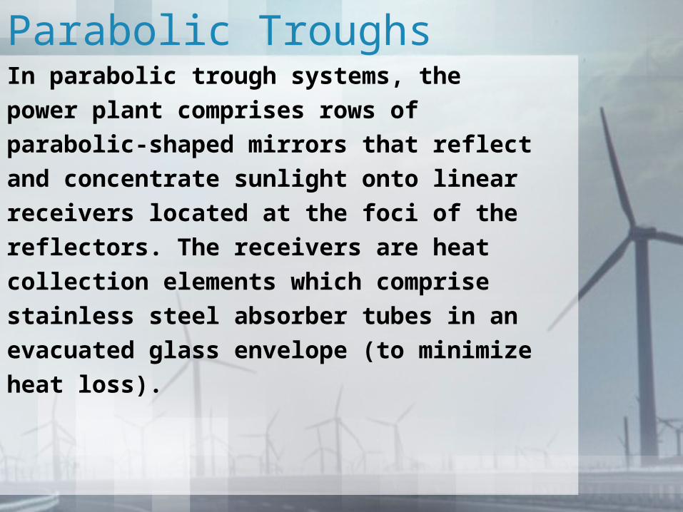
Parabolic TroughsIn parabolic trough systems, the
power plant comprises rows of
parabolic-shaped mirrors that reflect
and concentrate sunlight onto linear
receivers located at the foci of the
reflectors. The receivers are heat
collection elements which comprise
stainless steel absorber tubes in an
evacuated glass envelope (to minimize
heat loss).

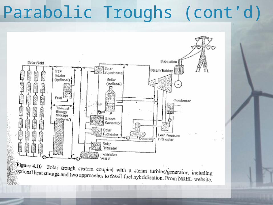
Parabolic Troughs (cont’d)A heat transfer fluid runs through the
stainless steel tubes and delivers the
heat to a conventional steam
turbine/generator.
Parabolic Troughs (cont’d)
Parabolic Troughs (cont’d)The heat transfer fluid is heated to
approximately 400ºC in the receiver
tubes. This fluid is passed through a
series of heat exchangers to generate
high-pressure, superheated steam for
the turbine. Thermal storage and/or
auxiliary fuel can be used to run the
plant when sufficient solar energy is
not available. This system uses a
considerable amount of cooling water.
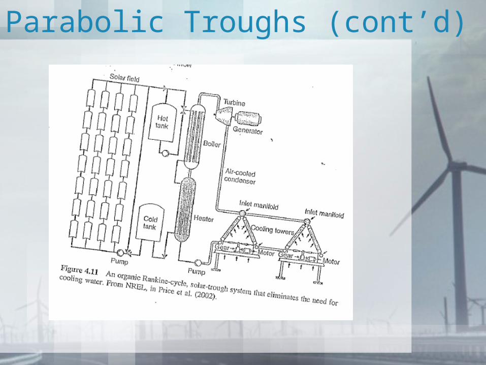
Parabolic Troughs (cont’d)One approach to avoiding precious
water consumption is based on a
modified, organic working fluid,
Rankine cycle technology (used in
geothermal plants). This fluid can be
condensed at above-atmospheric
pressures using air-cooled, fan-driven
cooling towers. This approach is
under evaluation.
Parabolic Troughs (cont’d)
Parabolic Troughs (cont’d) Existing parabolic trough power
plants include the SEGS power plants located in the Mojave desert near Bairstow, CA. This is a 354 MW facility. This system has operated reliably and cost-effectively (at a cost of about 12¢/kWh (2001 dollars)).
Parabolic Troughs (cont’d)
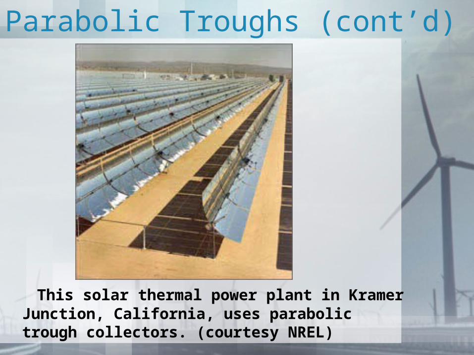
This solar thermal power plant in Kramer Junction, California, uses parabolic trough collectors. (courtesy NREL)
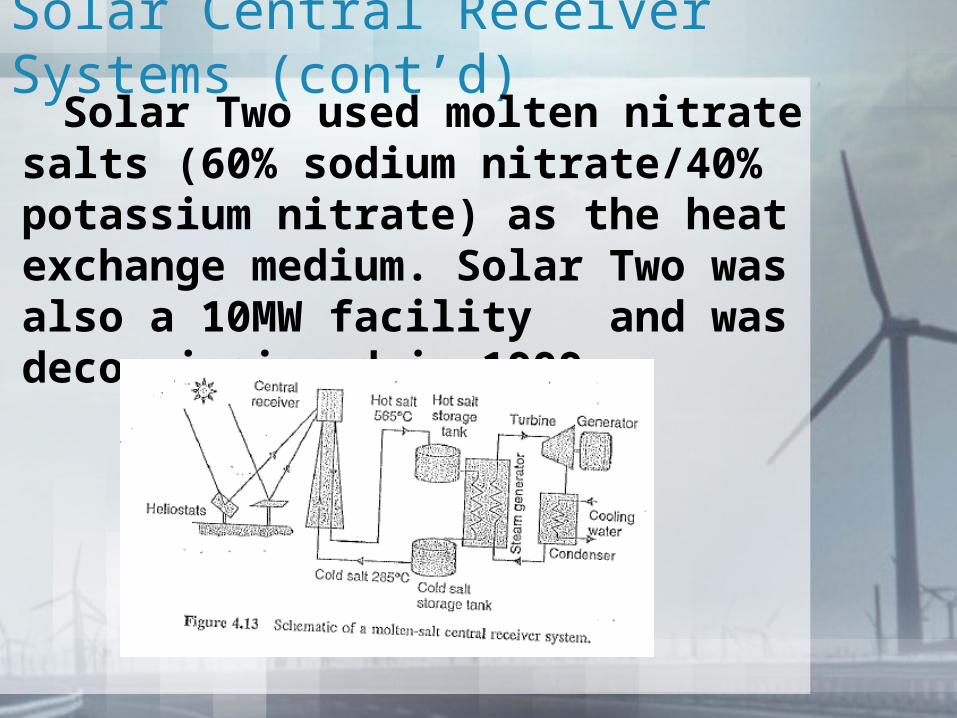
Solar Central Receiver Systems In this approach, heliostats (computer-
controlled mirrors) focus sunlight onto a central tower. This system is also sometimes referred to as a “power tower”. The first system, developed by Sandia National Labs, comprised a 90m tall tower and used water as the working fluid. The first plant, Solar One, was a 10MW power plant located near Barstow, CA. This ran from 1982-1988 after which Solar Two was built.
Solar Central Receiver Systems (cont’d)
Solar Two used molten nitrate salts (60% sodium nitrate/40% potassium nitrate) as the heat exchange medium. Solar Two was also a 10MW facility and was decommissioned in 1999.
Solar Central Receiver Systems
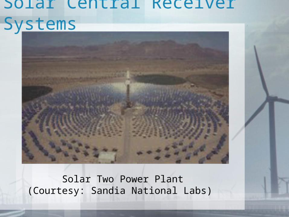
Solar Two Power Plant (Courtesy: Sandia National Labs)
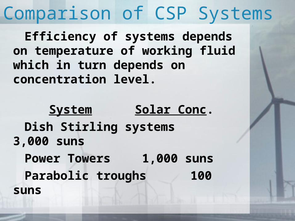
Comparison of CSP Systems Efficiency of systems depends on
temperature of working fluid which in turn depends on concentration level.
System Solar Conc.
Dish Stirling systems 3,000 suns
Power Towers 1,000 suns
Parabolic troughs 100 suns
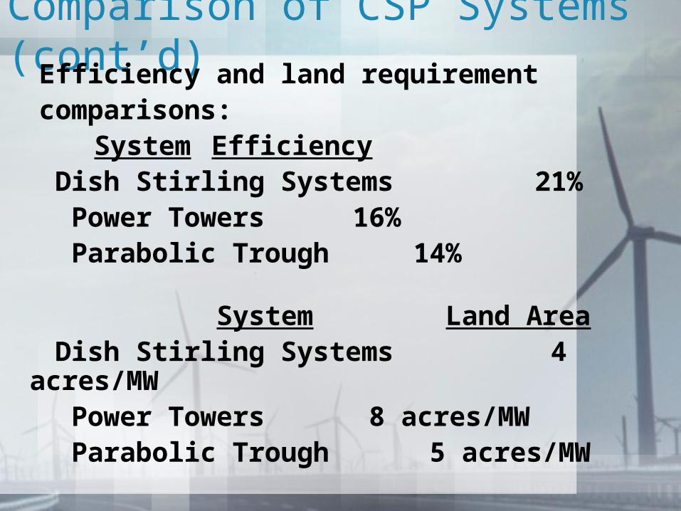
Comparison of CSP Systems (cont’d) Efficiency and land requirement comparisons:
System Efficiency Dish Stirling Systems 21% Power Towers 16% Parabolic Trough 14%
System Land Area Dish Stirling Systems 4 acres/MW Power Towers 8 acres/MW Parabolic Trough 5 acres/MW