Embed Size (px)
Citation preview

George Mason University
Dataflow Modeling of Combinational Logic
ECE 545 Lecture 5

2
Required reading
• P. Chu, RTL Hardware Design using VHDL Chapter 4, Concurrent Signal Assignment Statements of VHDL
3 ECE 448 – FPGA and ASIC Design with VHDL
Dataflow VHDL Design Style

4
VHDL Design Styles
Components and interconnects
structural
VHDL Design Styles
dataflow
Concurrent statements
behavioral (sequential)
• Registers • State machines • Instruction decoders
Sequential statements
Subset most suitable for synthesis
• Testbenches

5
Synthesizable VHDL
Dataflow VHDL Design Style
VHDL code synthesizable
VHDL code synthesizable
Dataflow VHDL Design Style

6
Register Transfer Level (RTL) Design Description
Combinational Logic
Combinational Logic
Registers
…
Today’s Topic

7
Data-Flow VHDL
• simple concurrent signal assignment (⇐)
• conditional concurrent signal assignment (when-else)
• selected concurrent signal assignment (with-select-when)
• generate scheme for equations (for-generate)
Concurrent Statements

8
Data-Flow VHDL
• simple concurrent signal assignment (⇐)
• conditional concurrent signal assignment (when-else)
• selected concurrent signal assignment (with-select-when)
• generate scheme for equations (for-generate)
Concurrent Statements

9 ECE 448 – FPGA and ASIC Design with VHDL
Wires and Buses

10
Signals
SIGNAL a : STD_LOGIC;
SIGNAL b : STD_LOGIC_VECTOR(7 DOWNTO 0);
wire
a
bus
b
1
8

11
Merging wires and buses
SIGNAL a: STD_LOGIC_VECTOR(3 DOWNTO 0); SIGNAL b: STD_LOGIC_VECTOR(4 DOWNTO 0); SIGNAL c: STD_LOGIC; SIGNAL d: STD_LOGIC_VECTOR(9 DOWNTO 0); d <= a & b & c;
4
5
10
a
b
c
d

12
Splitting buses
SIGNAL a: STD_LOGIC_VECTOR(3 DOWNTO 0); SIGNAL b: STD_LOGIC_VECTOR(4 DOWNTO 0); SIGNAL c: STD_LOGIC; SIGNAL d: STD_LOGIC_VECTOR(9 DOWNTO 0); a <= d(9 downto 6); b <= d(5 downto 1); c <= d(0);
4
5
10
a
b
c
d

13
Data-flow VHDL: Example
x y
cin s
cout

14
Data-flow VHDL: Example (1)
LIBRARY ieee ; USE ieee.std_logic_1164.all ; ENTITY fulladd IS
PORT ( x : IN STD_LOGIC ; y : IN STD_LOGIC ; cin : IN STD_LOGIC ;
s : OUT STD_LOGIC ; cout : OUT STD_LOGIC ) ; END fulladd ;

15
Data-flow VHDL: Example (2)
ARCHITECTURE dataflow OF fulladd IS BEGIN
s <= x XOR y XOR cin ; cout <= (x AND y) OR (cin AND x) OR (cin AND y) ;
END dataflow ;

16
Logic Operators
• Logic operators
• Logic operators precedence
and or nand nor xor not xnor
not and or nand nor xor xnor
Highest
Lowest
only in VHDL-93 or later

17
Wanted: y = ab + cd Incorrect y <= a and b or c and d ; equivalent to y <= ((a and b) or c) and d ; equivalent to y = (ab + c)d Correct y <= (a and b) or (c and d) ;
No Implied Precedence

RTL Hardware Design Chapter 4 18
• E.g., status <= '1'; even <= (p1 and p2) or (p3 and p4); arith_out <= a + b + c - 1;
• Implementation of last statement

RTL Hardware Design Chapter 4 19
Signal assignment statement with a closed feedback loop
• a signal appears in both sides of a concurrent assignment statement
• E.g., q <= ((not q) and (not en)) or (d and en);
• Syntactically correct • Form a closed feedback loop • Should be avoided

20
Data-Flow VHDL
• simple concurrent signal assignment (⇐)
• conditional concurrent signal assignment (when-else)
• selected concurrent signal assignment (with-select-when)
• generate scheme for equations (for-generate)
Concurrent Statements

21
Conditional concurrent signal assignment
target_signal <= value1 when condition1 else value2 when condition2 else . . . valueN-1 when conditionN-1 else valueN;
When - Else

22
Most often implied structure
target_signal <= value1 when condition1 else value2 when condition2 else . . . valueN-1 when conditionN-1 else valueN;
When - Else
.… Value N
Value N-1
Condition N-1
Condition 2 Condition 1
Value 2 Value 1
Target Signal
… 0 1
0 1
0 1

RTL Hardware Design Chapter 4 23
2-to-1 “abstract” mux • sel has a data type of boolean • If sel is true, the input from “T” port is connected
to output. • If sel is false, the input from “F” port is
connected to output.

RTL Hardware Design Chapter 4 24
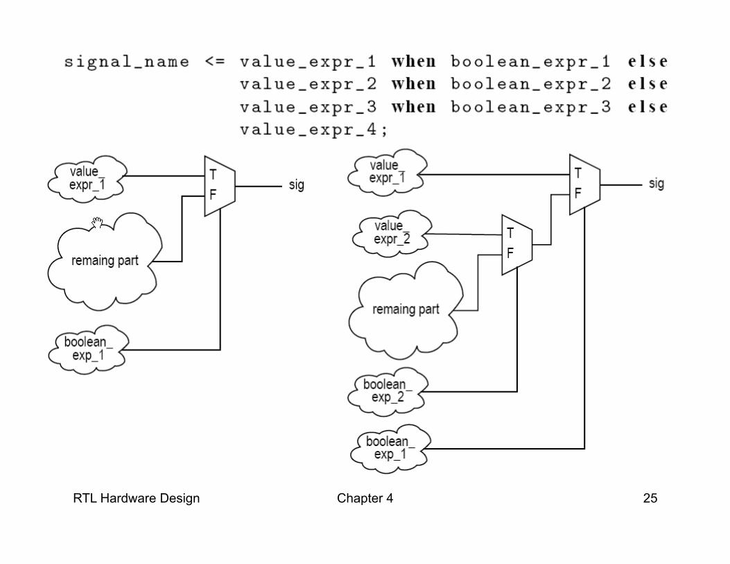
RTL Hardware Design Chapter 4 25

RTL Hardware Design Chapter 4 26

RTL Hardware Design Chapter 4 27
• E.g.,

RTL Hardware Design Chapter 4 28
• E.g.,

29
Signed and Unsigned Types
Behave exactly like STD_LOGIC_VECTOR plus, they determine whether a given vector should be treated as a signed or unsigned number. Require USE ieee.numeric_std.all;

30
Operators
• Relational operators
• Logic and relational operators precedence
= /= < <= > >=
not = /= < <= > >= and or nand nor xor xnor
Highest
Lowest

31
compare a = bc Incorrect … when a = b and c else … equivalent to … when (a = b) and c else … Correct … when a = (b and c) else …
Priority of logic and relational operators

32
Data-Flow VHDL
• simple concurrent signal assignment (⇐)
• conditional concurrent signal assignment (when-else)
• selected concurrent signal assignment (with-select-when)
• generate scheme for equations (for-generate)
Concurrent Statements
33
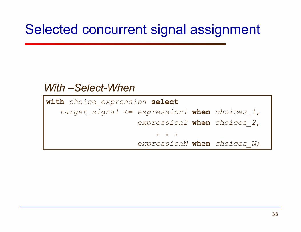
Selected concurrent signal assignment
with choice_expression select target_signal <= expression1 when choices_1, expression2 when choices_2, . . . expressionN when choices_N;
With –Select-When

34
Most Often Implied Structure
with choice_expression select target_signal <= expression1 when choices_1, expression2 when choices_2, . . . expressionN when choices_N;
With –Select-When
choices_1
choices_2
choices_N
expression1
target_signal
choice expression
expression2
expressionN

35
Allowed formats of choices_k
WHEN value WHEN value_1 | value_2 | .... | value N WHEN OTHERS
36
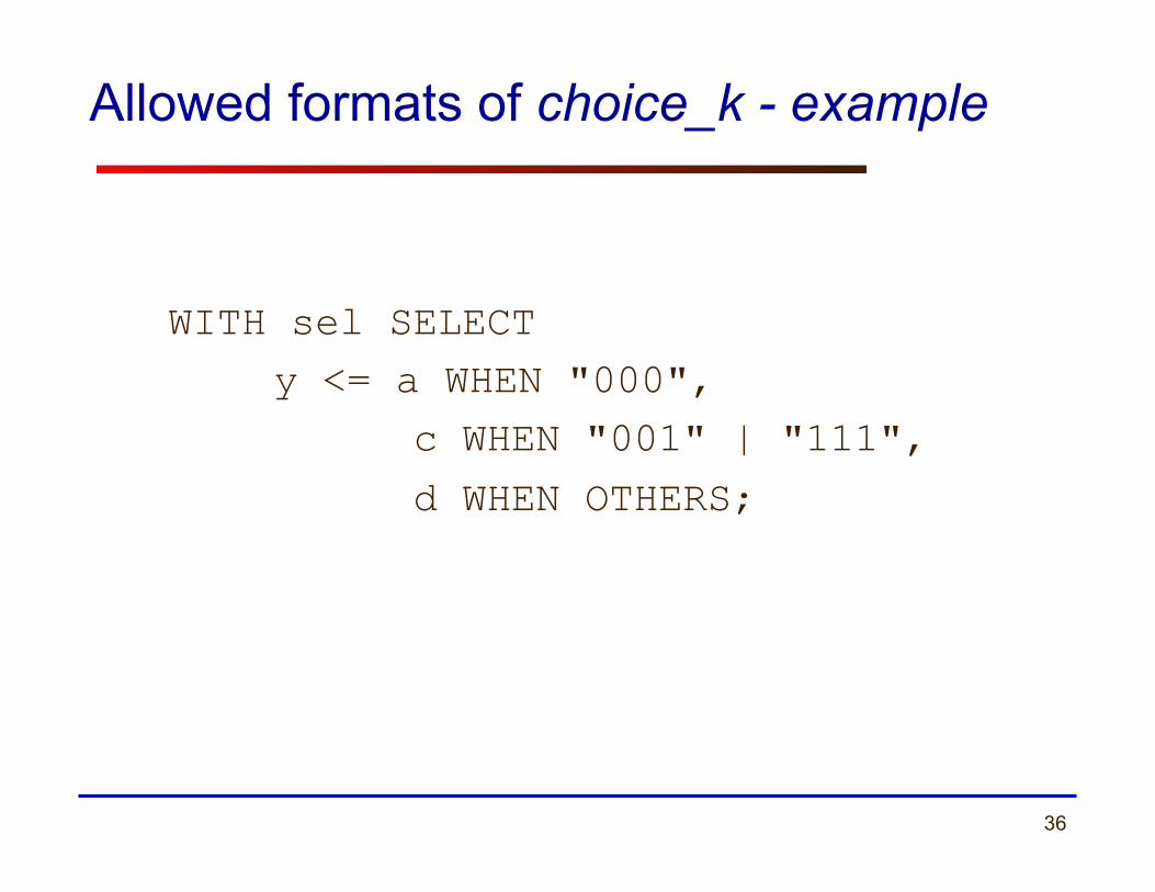
Allowed formats of choice_k - example
WITH sel SELECT y <= a WHEN "000",
c WHEN "001" | "111",
d WHEN OTHERS;

RTL Hardware Design Chapter 4 37
Syntax
• Simplified syntax: with select_expression select signal_name <= value_expr_1 when choice_1, value_expr_2 when choice_2, value_expr_3 when choice_3, . . . value_expr_n when choice_n;

RTL Hardware Design Chapter 4 38
• select_expression – Discrete type or 1-D array – With finite possible values
• choice_i – A value of the data type
• Choices must be – mutually exclusive – all inclusive – others can be used as last choice_i

RTL Hardware Design Chapter 4 39
E.g., 4-to-1 mux

RTL Hardware Design Chapter 4 40
• Can “11” be used to replace others?
RTL Hardware Design Chapter 4 41
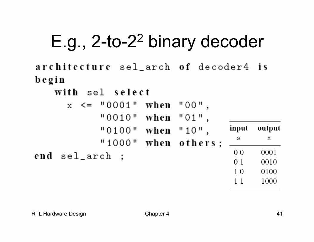
E.g., 2-to-22 binary decoder
RTL Hardware Design Chapter 4 42
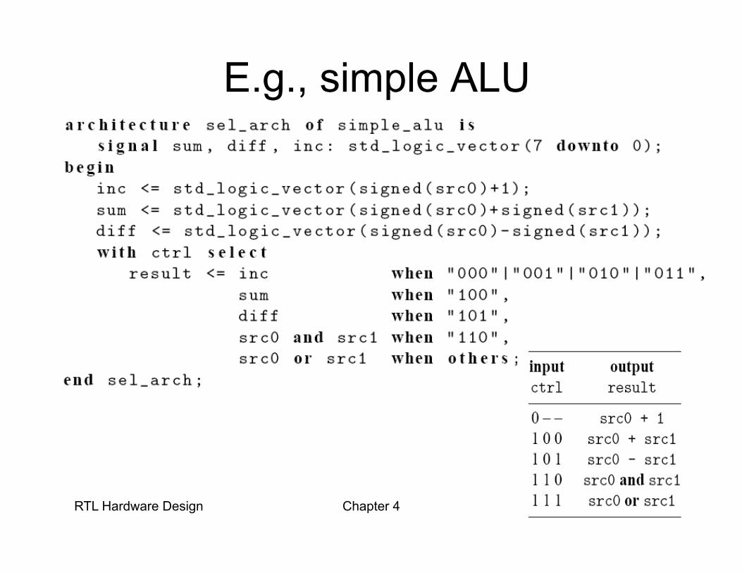
E.g., simple ALU

RTL Hardware Design Chapter 4 43
E.g., Truth table

RTL Hardware Design Chapter 4 44
Conceptual implementation
• Achieved by a multiplexing circuit
• Abstract (k+1)-to-1 multiplexer – sel is with a data type
of (k+1) values: c0, c1, c2, . . . , ck

RTL Hardware Design Chapter 4 45
– select_expression is with a data type of 5 values: c0, c1, c2, c3, c4

RTL Hardware Design Chapter 4 46

RTL Hardware Design Chapter 4 47
• E.g.,

RTL Hardware Design Chapter 4 48
3. Conditional vs. selected signal assignment
• Conversion between conditional vs. selected signal assignment
• Comparison

RTL Hardware Design Chapter 4 49
From selected assignment to conditional assignment

RTL Hardware Design Chapter 4 50
From conditional assignment to selected assignment

RTL Hardware Design Chapter 4 51
Comparison
• Selected signal assignment: – good match for a circuit described by a
functional table – E.g., binary decoder, multiplexer – Less effective when an input pattern is given a
preferential treatment

RTL Hardware Design Chapter 4 52
• Conditional signal assignment: – good match for a circuit that needs to give
preferential treatment for certain conditions or to prioritize the operations
– E.g., priority encoder – Can handle complicated conditions. e.g.,

RTL Hardware Design Chapter 4 53
– May “over-specify” for a functional table based circuit.
– E.g., mux

ECE 448 – FPGA and ASIC Design with VHDL
Modeling Common Combinational Logic Components
Using Dataflow VHDL

55 ECE 448 – FPGA and ASIC Design with VHDL
Fixed Shifters & Rotators

56
Fixed Logical Shift Right in VHDL
A(3) A(2) A(1) A(0)
‘0’ A(3) A(2) A(1)
SIGNAL A : STD_LOGIC_VECTOR(3 DOWNTO 0); SIGNAL C: STD_LOGIC_VECTOR(3 DOWNTO 0);
A
C =
C
4
4
A
C >>1

57
Fixed Arithmetic Shift Right in VHDL
A(3) A(2) A(1) A(0)
A(3) A(2) A(1)
SIGNAL A : STD_LOGIC_VECTOR(3 DOWNTO 0); SIGNAL C: STD_LOGIC_VECTOR(3 DOWNTO 0);
A
C =
C
4
4
A
C >>1
A(3)

58
Fixed Rotation in VHDL
A(3) A(2) A(1) A(0)
A(2) A(1) A(0) A(3)
SIGNAL A : STD_LOGIC_VECTOR(3 DOWNTO 0); SIGNAL C: STD_LOGIC_VECTOR(3 DOWNTO 0);
A 4
4
A
C <<< 1
C

59 ECE 448 – FPGA and ASIC Design with VHDL
Multiplexers

60 ECE 448 – FPGA and ASIC Design with VHDL
2-to-1 Multiplexer
(a) Graphical symbol (b) Truth table
0
1
f s
w 0
w 1
f
s
w 0
w 1
0
1

61 ECE 448 – FPGA and ASIC Design with VHDL
VHDL code for a 2-to-1 Multiplexer
LIBRARY ieee ; USE ieee.std_logic_1164.all ; ENTITY mux2to1 IS
PORT ( w0, w1, s : IN STD_LOGIC ; f : OUT STD_LOGIC ) ;
END mux2to1 ; ARCHITECTURE dataflow OF mux2to1 IS BEGIN
f <= w0 WHEN s = '0' ELSE w1 ; END dataflow ;

62 ECE 448 – FPGA and ASIC Design with VHDL
Cascade of two multiplexers
s1
w 3
w 1
0
1
s2
w 2
0
1 y

63 ECE 448 – FPGA and ASIC Design with VHDL
VHDL code for a cascade of two multiplexers
LIBRARY ieee ; USE ieee.std_logic_1164.all ; ENTITY mux_cascade IS
PORT ( w1, w2, w3: IN STD_LOGIC ; s1, s2 : IN STD_LOGIC ; f : OUT STD_LOGIC ) ;
END mux_cascade ; ARCHITECTURE dataflow OF mux2to1 IS BEGIN
f <= w1 WHEN s1 = ‘1' ELSE w2 WHEN s2 = ‘1’ ELSE w3 ; END dataflow ;
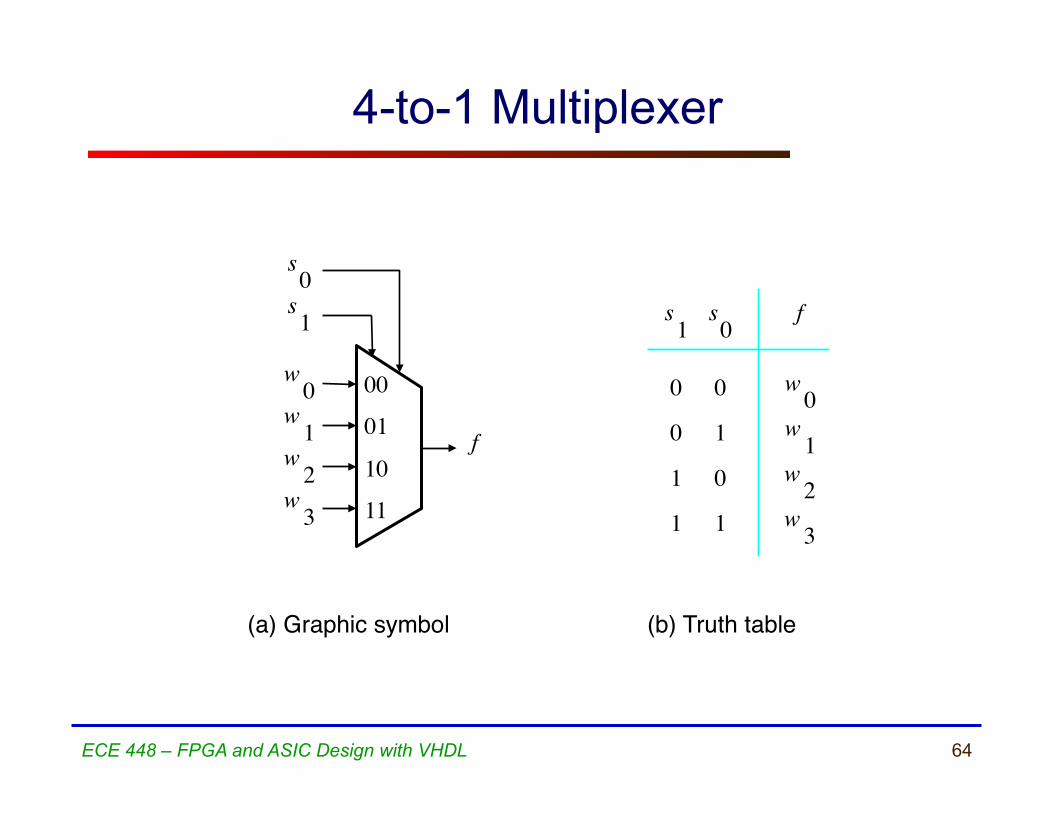
64 ECE 448 – FPGA and ASIC Design with VHDL
f
s 1
w 0
w 1
00
01
(b) Truth table
w 0
w 1
s 0
w 2
w 3
10
11
0
0
1
1
1
0
1
f s 1
0
s 0
w 2
w 3
(a) Graphic symbol
4-to-1 Multiplexer

65 ECE 448 – FPGA and ASIC Design with VHDL
VHDL code for a 4-to-1 Multiplexer
LIBRARY ieee ; USE ieee.std_logic_1164.all ; ENTITY mux4to1 IS
PORT ( w0, w1, w2, w3 : IN STD_LOGIC ; s : IN STD_LOGIC_VECTOR(1 DOWNTO 0) ; f : OUT STD_LOGIC ) ;
END mux4to1 ; ARCHITECTURE dataflow OF mux4to1 IS BEGIN
WITH s SELECT f <= w0 WHEN "00", w1 WHEN "01", w2 WHEN "10", w3 WHEN OTHERS ;
END dataflow ;

66 ECE 448 – FPGA and ASIC Design with VHDL
Variable Rotators

67 ECE 448 – FPGA and ASIC Design with VHDL
8-bit Variable Rotator Left
8
8
3
A
B
C
A <<< B

68 ECE 448 – FPGA and ASIC Design with VHDL
Adders

69
Adder mod 28
8 8
X Y
8
S

70
VHDL code for an Adder mod 28
LIBRARY ieee ; USE ieee.std_logic_1164.all ; USE ieee.std_logic_unsigned.all ; ENTITY adder16 IS
PORT ( X : IN STD_LOGIC_VECTOR(7 DOWNTO 0) ; Y : IN STD_LOGIC_VECTOR(7 DOWNTO 0) ; S : OUT STD_LOGIC_VECTOR(7 DOWNTO 0) ) ;
END adder16 ; ARCHITECTURE dataflow OF adder16 IS BEGIN
S <= X + Y ; END dataflow ;
71 ECE 448 – FPGA and ASIC Design with VHDL
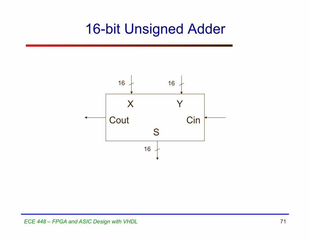
16-bit Unsigned Adder
16 16
X Y
16
Cin Cout S

72 ECE 448 – FPGA and ASIC Design with VHDL
Operations on Unsigned Numbers For operations on unsigned numbers USE ieee.std_logic_unsigned.all and signals of the type STD_LOGIC_VECTOR OR USE ieee.numeric_std.all, signals of the type UNSIGNED and conversion functions: std_logic_vector(), unsigned()
73 ECE 448 – FPGA and ASIC Design with VHDL
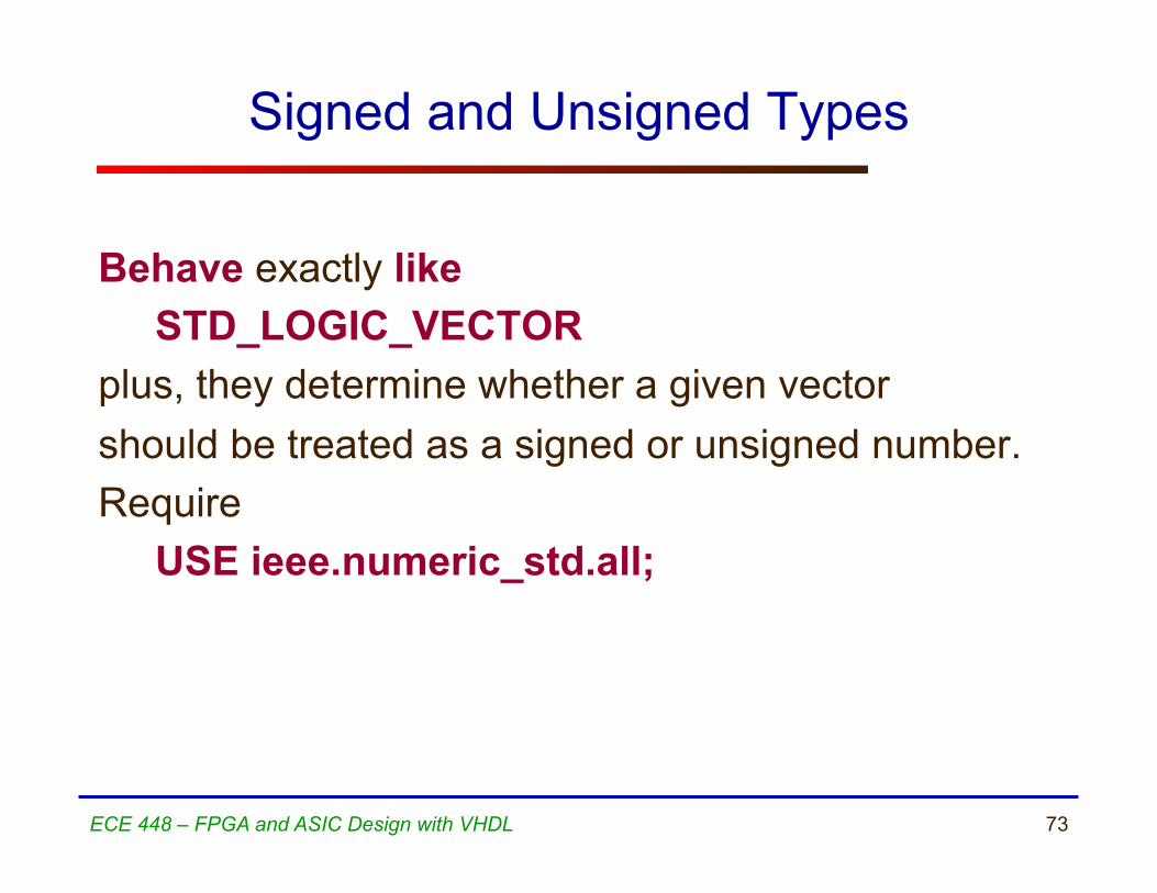
Signed and Unsigned Types
Behave exactly like STD_LOGIC_VECTOR plus, they determine whether a given vector should be treated as a signed or unsigned number. Require USE ieee.numeric_std.all;

74
VHDL code for a 16-bit Unsigned Adder
LIBRARY ieee ; USE ieee.std_logic_1164.all ; USE ieee.std_logic_unsigned.all ; ENTITY adder16 IS
PORT ( Cin : IN STD_LOGIC ; X : IN STD_LOGIC_VECTOR(15 DOWNTO 0) ; Y : IN STD_LOGIC_VECTOR(15 DOWNTO 0) ; S : OUT STD_LOGIC_VECTOR(15 DOWNTO 0) ; Cout : OUT STD_LOGIC ) ;
END adder16 ; ARCHITECTURE dataflow OF adder16 IS
SIGNAL Sum : STD_LOGIC_VECTOR(16 DOWNTO 0) ; BEGIN
Sum <= ('0' & X) + Y + Cin ; S <= Sum(15 DOWNTO 0) ; Cout <= Sum(16) ;
END dataflow ;

75 ECE 448 – FPGA and ASIC Design with VHDL
Addition of Unsigned Numbers (1)
LIBRARY ieee ; USE ieee.std_logic_1164.all ; USE ieee.numeric_std.all ; ENTITY adder16 IS
PORT ( Cin : IN STD_LOGIC ; X : IN STD_LOGIC_VECTOR(15 DOWNTO 0) ; Y : IN STD_LOGIC_VECTOR(15 DOWNTO 0) ; S : OUT STD_LOGIC_VECTOR(15 DOWNTO 0) ; Cout : OUT STD_LOGIC ) ;
END adder16 ;
76 ECE 448 – FPGA and ASIC Design with VHDL
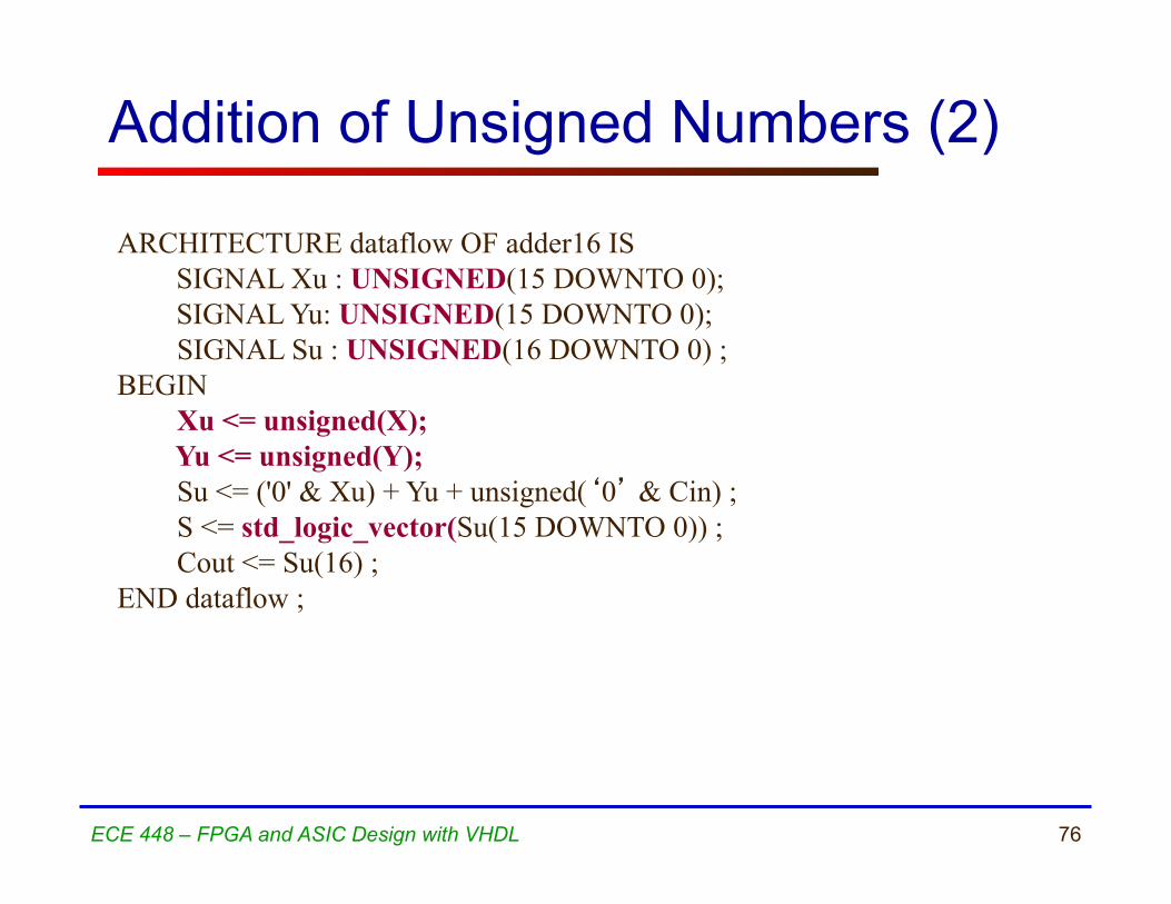
Addition of Unsigned Numbers (2) ARCHITECTURE dataflow OF adder16 IS SIGNAL Xu : UNSIGNED(15 DOWNTO 0); SIGNAL Yu: UNSIGNED(15 DOWNTO 0);
SIGNAL Su : UNSIGNED(16 DOWNTO 0) ; BEGIN
Xu <= unsigned(X); Yu <= unsigned(Y);
Su <= ('0' & Xu) + Yu + unsigned(‘0’ & Cin) ; S <= std_logic_vector(Su(15 DOWNTO 0)) ; Cout <= Su(16) ;
END dataflow ;

77 ECE 448 – FPGA and ASIC Design with VHDL
Operations on Signed Numbers
For operations on signed numbers USE ieee.std_logic_signed.all and signals of the type STD_LOGIC_VECTOR OR USE ieee.numeric_std.all, signals of the type SIGNED, and conversion functions: std_logic_vector(), signed()

78 ECE 448 – FPGA and ASIC Design with VHDL
Multipliers

79 ECE 448 – FPGA and ASIC Design with VHDL
Unsigned vs. Signed Multiplication
1111 1111 x
11100001
15 15 x
225
1111 1111 x
00000001
-1 -1 x
1
Unsigned Signed
80 ECE 448 – FPGA and ASIC Design with VHDL
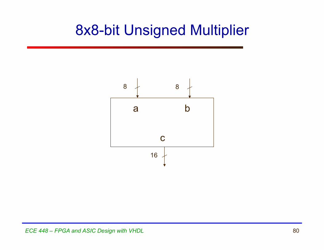
8x8-bit Unsigned Multiplier
8 8
a b
16
c

81 ECE 448 – FPGA and ASIC Design with VHDL
Multiplication of unsigned numbers
LIBRARY ieee; USE ieee.std_logic_1164.all; USE ieee.std_logic_unsigned.all ; entity multiply is
port( a : in STD_LOGIC_VECTOR(7 downto 0); b : in STD_LOGIC_VECTOR(7 downto 0); c : out STD_LOGIC_VECTOR(15 downto 0) );
end multiply; architecture dataflow of multiply is begin
c <= a * b; end dataflow;

82 ECE 448 – FPGA and ASIC Design with VHDL
8x8-bit Signed Multiplier
8 8
a b
16
c

83 ECE 448 – FPGA and ASIC Design with VHDL
Multiplication of signed numbers
LIBRARY ieee; USE ieee.std_logic_1164.all; USE ieee.std_logic_signed.all ; entity multiply is
port( a : in STD_LOGIC_VECTOR(7 downto 0); b : in STD_LOGIC_VECTOR(7 downto 0); c : out STD_LOGIC_VECTOR(15 downto 0) );
end multiply; architecture dataflow of multiply is begin
c <= a * b; end dataflow;

84 ECE 448 – FPGA and ASIC Design with VHDL
8x8-bit Unsigned and Signed Multiplier
8 8
a b
16
cu
16
cs
85 ECE 448 – FPGA and ASIC Design with VHDL
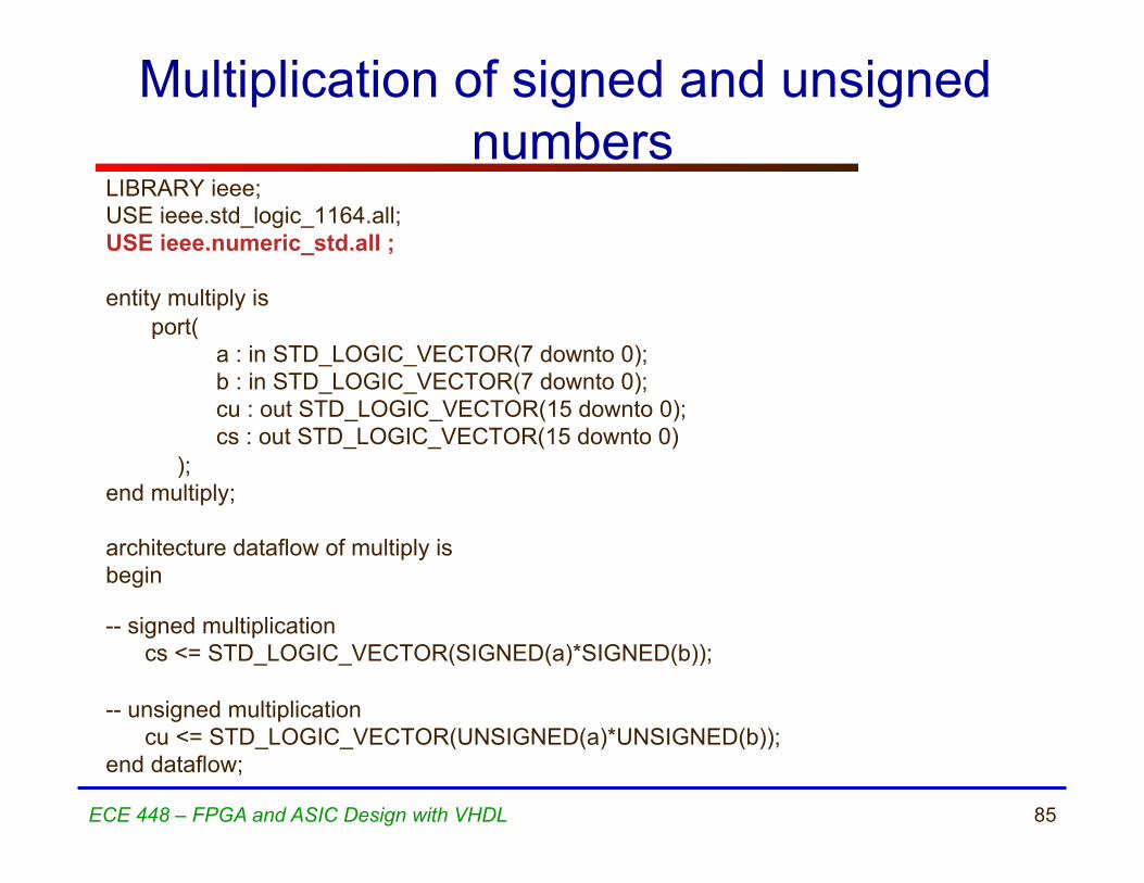
Multiplication of signed and unsigned numbers
LIBRARY ieee; USE ieee.std_logic_1164.all; USE ieee.numeric_std.all ; entity multiply is
port( a : in STD_LOGIC_VECTOR(7 downto 0); b : in STD_LOGIC_VECTOR(7 downto 0); cu : out STD_LOGIC_VECTOR(15 downto 0); cs : out STD_LOGIC_VECTOR(15 downto 0) );
end multiply; architecture dataflow of multiply is begin
-- signed multiplication
cs <= STD_LOGIC_VECTOR(SIGNED(a)*SIGNED(b)); -- unsigned multiplication
cu <= STD_LOGIC_VECTOR(UNSIGNED(a)*UNSIGNED(b)); end dataflow;

86 ECE 448 – FPGA and ASIC Design with VHDL
Comparators

87 ECE 448 – FPGA and ASIC Design with VHDL
4-bit Number Comparator
4
4
A
B
AeqB AgtB
AltB

88 ECE 448 – FPGA and ASIC Design with VHDL
VHDL code for a 4-bit Unsigned Number Comparator
LIBRARY ieee ; USE ieee.std_logic_1164.all ; USE ieee.std_logic_unsigned.all ; ENTITY compare IS
PORT ( A, B : IN STD_LOGIC_VECTOR(3 DOWNTO 0) ; AeqB, AgtB, AltB : OUT STD_LOGIC ) ;
END compare ; ARCHITECTURE dataflow OF compare IS BEGIN
AeqB <= '1' WHEN A = B ELSE '0' ; AgtB <= '1' WHEN A > B ELSE '0' ; AltB <= '1' WHEN A < B ELSE '0' ;
END dataflow ;
89 ECE 448 – FPGA and ASIC Design with VHDL
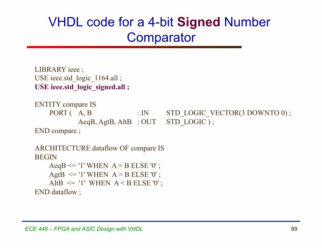
VHDL code for a 4-bit Signed Number Comparator
LIBRARY ieee ; USE ieee.std_logic_1164.all ; USE ieee.std_logic_signed.all ; ENTITY compare IS
PORT ( A, B : IN STD_LOGIC_VECTOR(3 DOWNTO 0) ; AeqB, AgtB, AltB : OUT STD_LOGIC ) ;
END compare ; ARCHITECTURE dataflow OF compare IS BEGIN
AeqB <= '1' WHEN A = B ELSE '0' ; AgtB <= '1' WHEN A > B ELSE '0' ; AltB <= '1' WHEN A < B ELSE '0' ;
END dataflow ;

90 ECE 448 – FPGA and ASIC Design with VHDL
Arithmetic operations
Synthesizable arithmetic operations: • Addition, + • Subtraction, - • Comparisons, >, >=, <, <= • Multiplication, * • Division by a power of 2, /2**6
(equivalent to right shift)

91 ECE 448 – FPGA and ASIC Design with VHDL
Arithmetic operations
The result of synthesis of an arithmetic operation is a - combinational circuit - without pipelining. The exact internal architecture used (and thus delay and area of the circuit) may depend on the timing constraints specified during synthesis (e.g., the requested maximum clock frequency).

92 ECE 448 – FPGA and ASIC Design with VHDL
Integer Types
Operations on signals of the integer types: INTEGER, NATURAL, and their sybtypes, such as TYPE day_of_month IS RANGE 1 TO 31; are synthesizable in the range
-(231-1) .. 231 -1 for INTEGERs and their subtypes 0 .. 231 -1 for NATURALs and their subtypes

93 ECE 448 – FPGA and ASIC Design with VHDL
Integer Types
Operations on signals (variables) of the integer types: INTEGER, NATURAL, are less flexible and more difficult to control than operations on signals (variables) of the type
STD_LOGIC_VECTOR UNSIGNED SIGNED, and thus
are recommened to be avoided by beginners.

94 ECE 448 – FPGA and ASIC Design with VHDL
ROM

95 ECE 448 – FPGA and ASIC Design with VHDL
8-bit Variable Rotator Left
3
16
Addr
C
8x16 ROM Dout

96
Instruction ROM example (1)
LIBRARY ieee; USE ieee.std_logic_1164.all; USE ieee.numeric_std.all; ENTITY rom IS
PORT ( Addr : IN STD_LOGIC_VECTOR(2 DOWNTO 0); Dout : OUT STD_LOGIC_VECTOR(15 DOWNTO 0) );
END rom;

97
Instruction ROM example (2) ARCHITECTURE dataflow OF rom IS SIGNAL temp: INTEGER RANGE 0 TO 7; TYPE vector_array IS ARRAY (0 to 7) OF STD_LOGIC_VECTOR(15 DOWNTO 0); CONSTANT memory : vector_array :=
( X”800A", X"D459", X"A870", X"7853", X"650D", X"642F", X"F742", X"F548");
BEGIN temp <= to_integer(unsigned(Addr));
Dout <= memory(temp);
END dataflow;

98 ECE 448 – FPGA and ASIC Design with VHDL
Decoders

99 ECE 448 – FPGA and ASIC Design with VHDL
2-to-4 Decoder
0
0
1
1
1
0
1
y 3
w 1
0
w 0
x x
1
1
0
1
1
En
0
0
1
0
0
y 2
0
1
0
0
0
y 1
1
0
0
0
0
y 0
0
0
0
1
0
w 1
En
y 3
w 0
y 2
y 1
y 0
(a) Truth table (b) Graphical symbol

100 ECE 448 – FPGA and ASIC Design with VHDL
VHDL code for a 2-to-4 Decoder LIBRARY ieee ; USE ieee.std_logic_1164.all ; ENTITY dec2to4 IS
PORT ( w : IN STD_LOGIC_VECTOR(1 DOWNTO 0) ; En : IN STD_LOGIC ; y : OUT STD_LOGIC_VECTOR(3 DOWNTO 0) ) ;
END dec2to4 ; ARCHITECTURE dataflow OF dec2to4 IS
SIGNAL Enw : STD_LOGIC_VECTOR(2 DOWNTO 0) ; BEGIN
Enw <= En & w ; WITH Enw SELECT y <= “0001" WHEN "100", "0010" WHEN "101", "0100" WHEN "110", “1000" WHEN "111", "0000" WHEN OTHERS ;
END dataflow ;

101 ECE 448 – FPGA and ASIC Design with VHDL
Encoders

102 ECE 448 – FPGA and ASIC Design with VHDL
Priority Encoder
w 0
w 3
y 0 y 1
d 0 0 1
0 1 0
w 0 y 1 d
y 0
1 1
0 1
1
1 1
z
1 x x
0
x
w 1
0 1 x
0
x
w 2
0 0 1
0
x
w 3
0 0 0
0
1
z
w 1 w 2

103 ECE 448 – FPGA and ASIC Design with VHDL
VHDL code for a Priority Encoder LIBRARY ieee ; USE ieee.std_logic_1164.all ; ENTITY priority IS
PORT ( w : IN STD_LOGIC_VECTOR(3 DOWNTO 0) ; y : OUT STD_LOGIC_VECTOR(1 DOWNTO 0) ; z : OUT STD_LOGIC ) ;
END priority ; ARCHITECTURE dataflow OF priority IS BEGIN
y <= "11" WHEN w(3) = '1' ELSE "10" WHEN w(2) = '1' ELSE "01" WHEN w(1) = '1' ELSE "00" ; z <= '0' WHEN w = "0000" ELSE '1' ;
END dataflow ;

104 ECE 448 – FPGA and ASIC Design with VHDL
Buffers

105 ECE 448 – FPGA and ASIC Design with VHDL
(b) Equivalent circuit
(c) Truth table
x f
e
(a) A tri-state buffer
0 0 1 1
0 1 0 1
Z Z 0 1
f e x
x f
e = 0
e = 1 x f
Tri-state Buffer
106 ECE 448 – FPGA and ASIC Design with VHDL
x f
e
(b)
x f
e
(a)
x f
e
(c)
x f
e
(d)
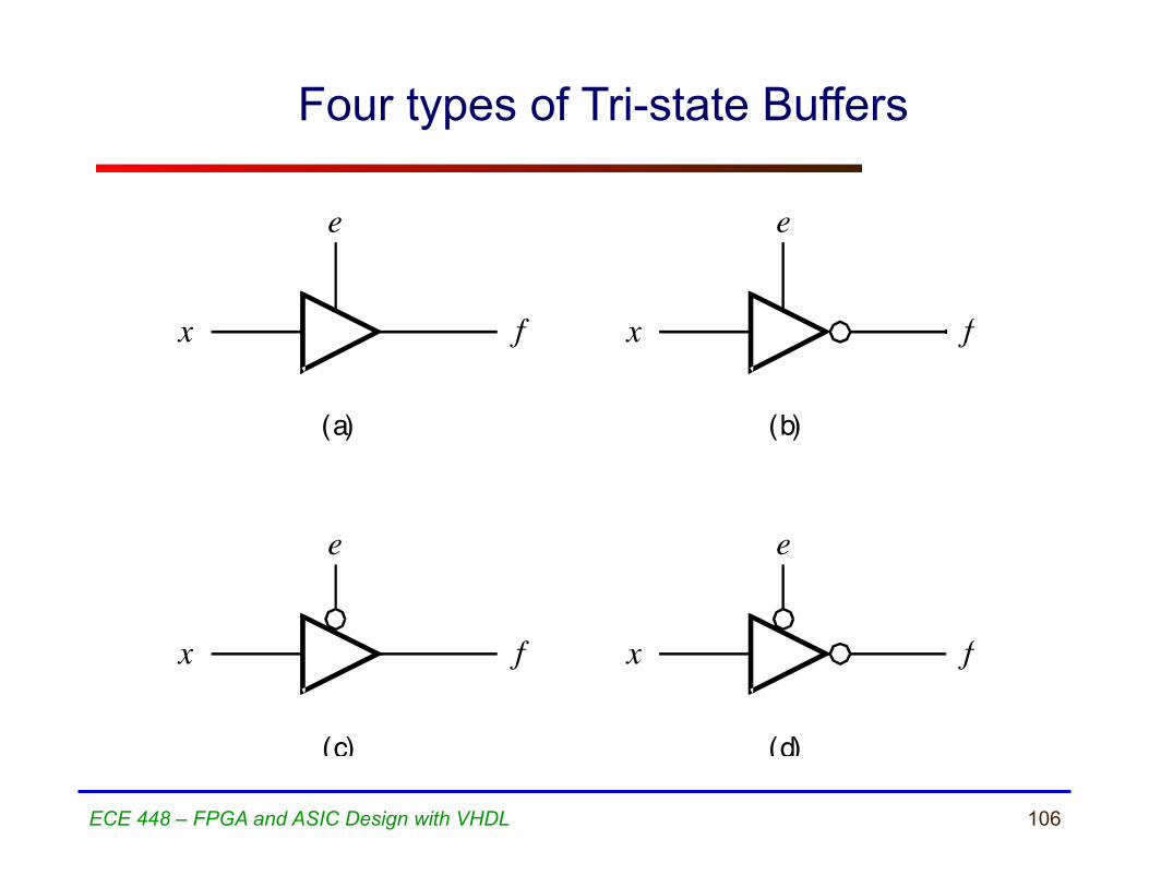
Four types of Tri-state Buffers
107 ECE 448 – FPGA and ASIC Design with VHDL
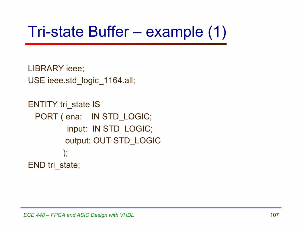
Tri-state Buffer – example (1)
LIBRARY ieee; USE ieee.std_logic_1164.all; ENTITY tri_state IS PORT ( ena: IN STD_LOGIC;
input: IN STD_LOGIC; output: OUT STD_LOGIC ); END tri_state;

108 ECE 448 – FPGA and ASIC Design with VHDL
Tri-state Buffer – example (2)
ARCHITECTURE dataflow OF tri_state IS BEGIN output <= input WHEN (ena = ‘1’) ELSE ‘Z’; END dataflow;

109
MLU Example

110
MLU Block Diagram
B
A
NEG_A
NEG_B
IN0 IN1 IN2 IN3
OUTPUT SEL1 SEL0
MUX_4_1
L0 L1
NEG_Y
Y Y1
A1
B1
MUX_0
MUX_1 MUX_2
MUX_3
0 1
0 1
0 1

111
MLU: Entity Declaration
LIBRARY ieee; USE ieee.std_logic_1164.all; ENTITY mlu IS
PORT( NEG_A : IN STD_LOGIC; NEG_B : IN STD_LOGIC; NEG_Y : IN STD_LOGIC; A : IN STD_LOGIC; B : IN STD_LOGIC; L1 : IN STD_LOGIC; L0 : IN STD_LOGIC; Y : OUT STD_LOGIC );
END mlu;

112
MLU: Architecture Declarative Section
ARCHITECTURE mlu_dataflow OF mlu IS
SIGNAL A1 : STD_LOGIC; SIGNAL B1 : STD_LOGIC; SIGNAL Y1 : STD_LOGIC; SIGNAL MUX_0 : STD_LOGIC; SIGNAL MUX_1 : STD_LOGIC; SIGNAL MUX_2 : STD_LOGIC; SIGNAL MUX_3 : STD_LOGIC; SIGNAL L: STD_LOGIC_VECTOR(1 DOWNTO 0);
113
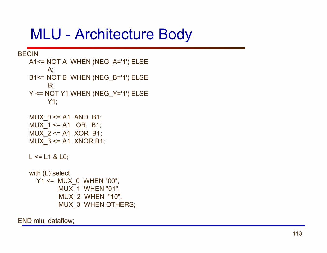
MLU - Architecture Body BEGIN
A1<= NOT A WHEN (NEG_A='1') ELSE A; B1<= NOT B WHEN (NEG_B='1') ELSE B; Y <= NOT Y1 WHEN (NEG_Y='1') ELSE Y1; MUX_0 <= A1 AND B1; MUX_1 <= A1 OR B1; MUX_2 <= A1 XOR B1; MUX_3 <= A1 XNOR B1;
L <= L1 & L0;
with (L) select Y1 <= MUX_0 WHEN "00",
MUX_1 WHEN "01", MUX_2 WHEN "10", MUX_3 WHEN OTHERS;
END mlu_dataflow;