Embed Size (px)
Citation preview
1
ECE 545—Digital System Design with VHDL Lecture 1
Digital Logic Refresher Part A – Combinational Logic Building Blocks
2
Lecture Roadmap – Combinational Logic
• Basic Logic Review • Basic Gates • De Morgan’s Law
• Combinational Logic Building Blocks • Multiplexers • Decoders, Demultiplexers • Encoders, Priority Encoders • Arithmetic circuits • ROM. Implementing combinational logic using ROM. • Tri-state buffers.
3
Textbook References
• Combinational Logic Review
• Stephen Brown and Zvonko Vranesic,
Fundamentals of Digital Logic with VHDL Design, 2nd or 3rd Edition
§ Chapter 2 Introduction to Logic Circuits (2.1-2.8 only)
§ Chapter 6 Combinational-Circuit Building Blocks (6.1-6.5 only)
• OR your undergraduate digital logic textbook (chapters on combinational logic)
4
Basic Logic Review
some slides modified from: S. Dandamudi, “Fundamentals of Computer Organization and Design”
5
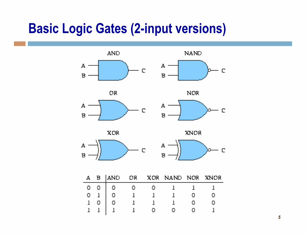
Basic Logic Gates (2-input versions)
6
Basic Logic Gates Generalized
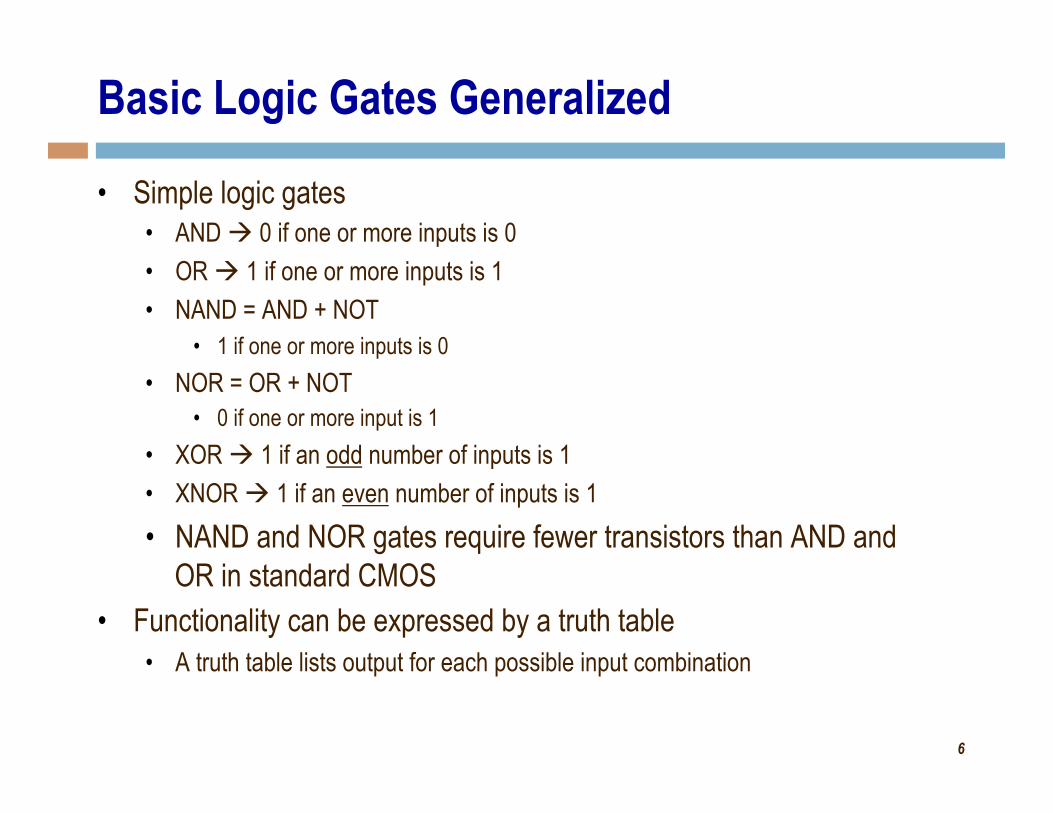
• Simple logic gates • AND à 0 if one or more inputs is 0 • OR à 1 if one or more inputs is 1 • NAND = AND + NOT
• 1 if one or more inputs is 0 • NOR = OR + NOT
• 0 if one or more input is 1 • XOR à 1 if an odd number of inputs is 1 • XNOR à 1 if an even number of inputs is 1 • NAND and NOR gates require fewer transistors than AND and
OR in standard CMOS • Functionality can be expressed by a truth table
• A truth table lists output for each possible input combination
7
Number of Functions
• Number of functions • With N logical variables, we can define
22N functions • Some of them are useful
• AND, NAND, NOR, XOR, … • Some are not useful:
• Output is always 1 • Output is always 0
• “Number of functions” definition is useful in proving completeness property
8
Complete Set of Gates
• Complete sets • A set of gates is complete
• if we can implement any logic function using only the type of gates in the set
• Some example complete sets • {AND, OR, NOT} Not a minimal complete set • {AND, NOT} • {OR, NOT} • {NAND} • {NOR}
• Minimal complete set • A complete set with no redundant elements.
9
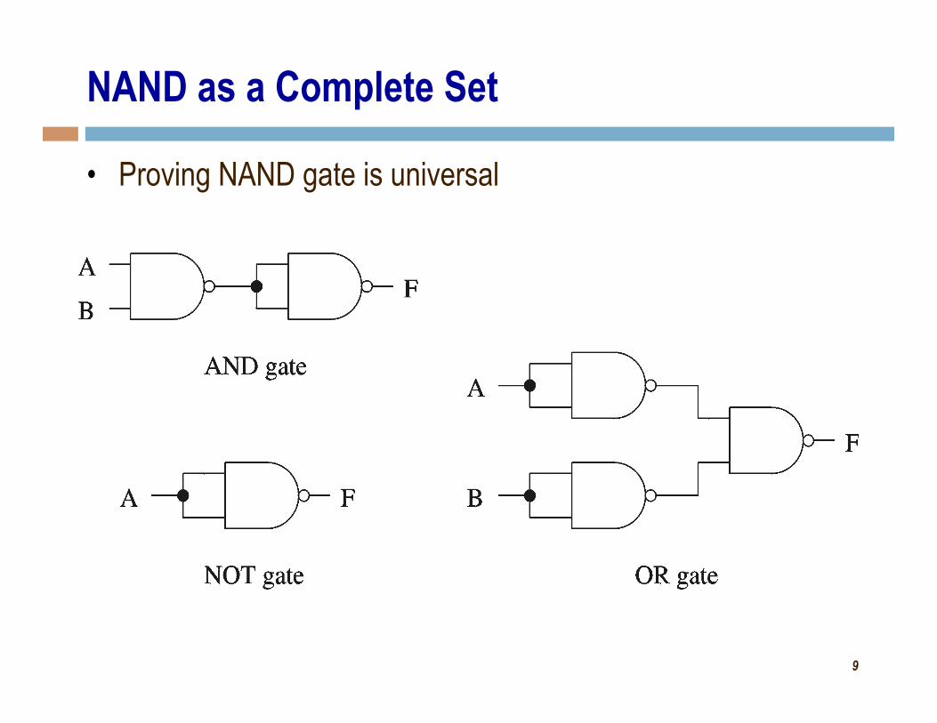
NAND as a Complete Set
• Proving NAND gate is universal
10
Logic Functions
• Logic functions can be expressed in several ways: • Truth table • Logical expressions • Graphical schematic form • HDL code
• Example: • Majority function
• Output is one whenever majority of inputs is 1 • We use 3-input majority function

11
Alternative Representations of Logic Function
Truth table A B C F
0 0 0 0 0 0 1 0 0 1 0 0 0 1 1 1 1 0 0 0 1 0 1 1 1 1 0 1 1 1 1 1
Logical expression form F = A B + B C + A C
Graphical schematic form
F <= (A AND B) OR (B AND C) OR (A AND C) ; HDL code:
12
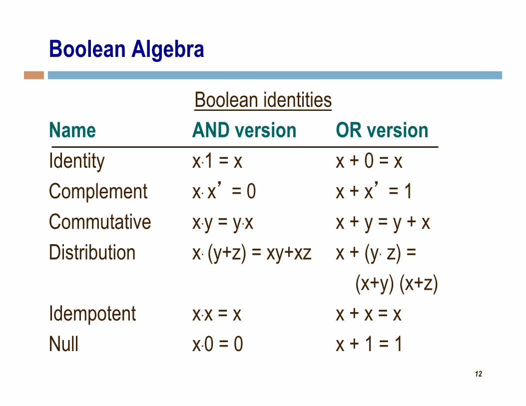
Boolean Algebra
Boolean identities Name AND version OR version Identity x.1 = x x + 0 = x Complement x. x’ = 0 x + x’ = 1 Commutative x.y = y.x x + y = y + x Distribution x. (y+z) = xy+xz x + (y. z) =
(x+y) (x+z) Idempotent x.x = x x + x = x Null x.0 = 0 x + 1 = 1
13
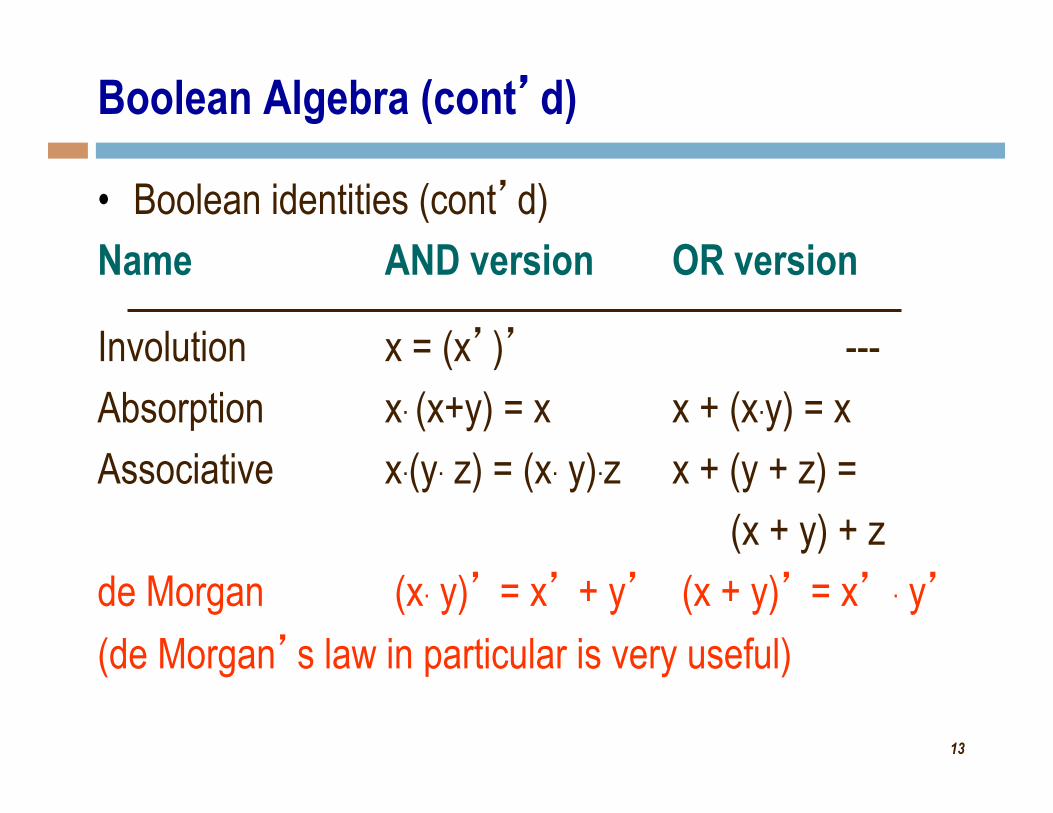
Boolean Algebra (cont’d)
• Boolean identities (cont’d) Name AND version OR version Involution x = (x’)’ --- Absorption x. (x+y) = x x + (x.y) = x Associative x.(y. z) = (x. y).z x + (y + z) =
(x + y) + z de Morgan (x. y)’ = x’ + y’ (x + y)’ = x’ . y’ (de Morgan’s law in particular is very useful)
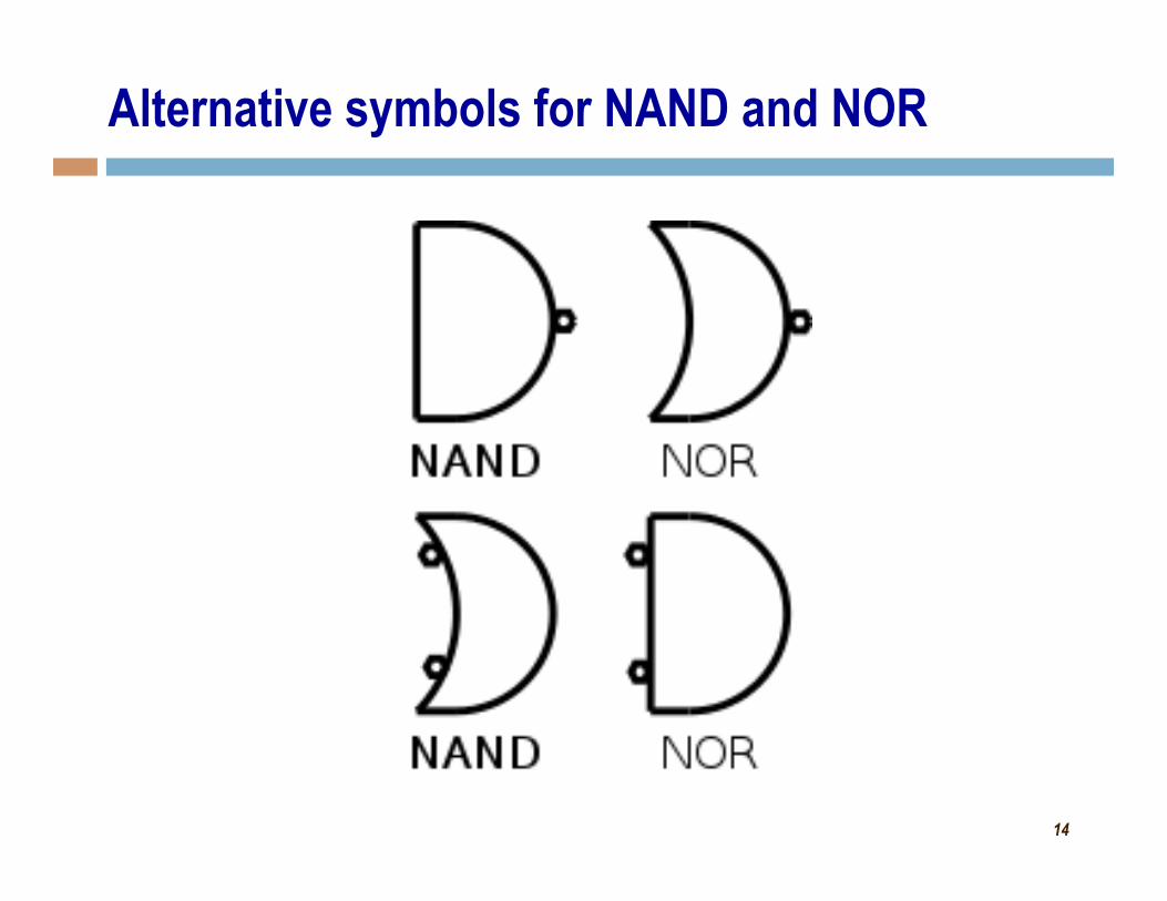
14
Alternative symbols for NAND and NOR
15
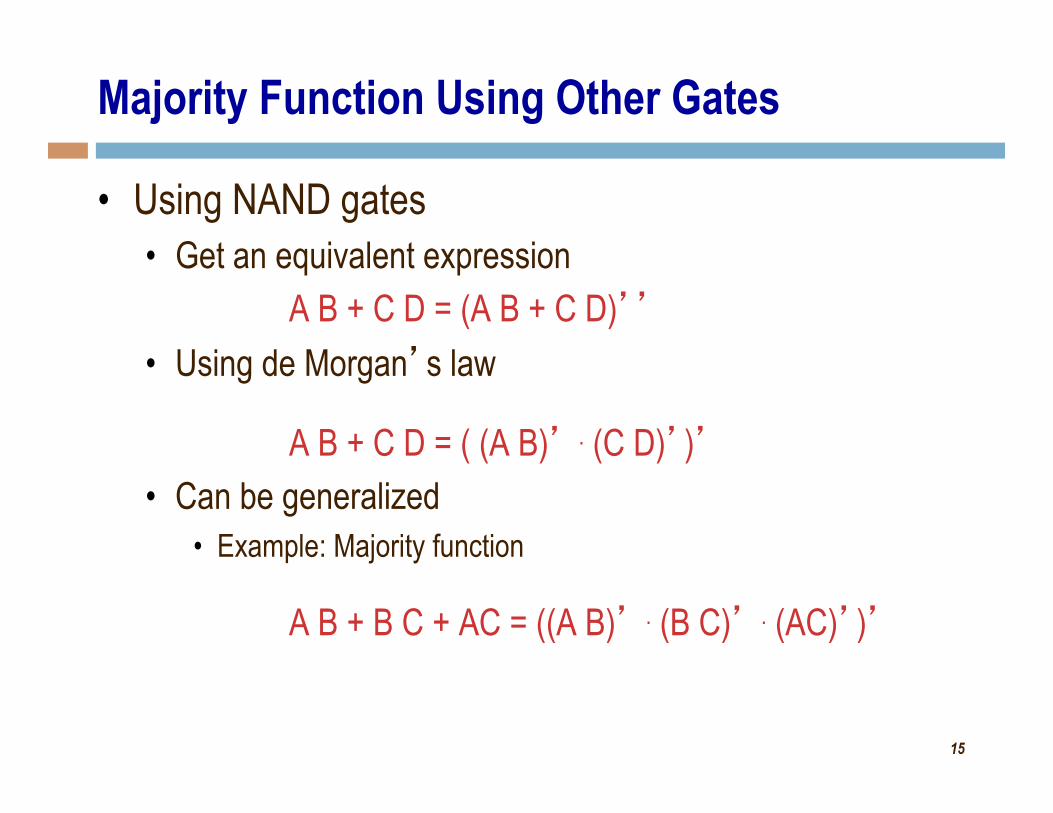
Majority Function Using Other Gates
• Using NAND gates • Get an equivalent expression
A B + C D = (A B + C D)’’ • Using de Morgan’s law
A B + C D = ( (A B)’ . (C D)’)’ • Can be generalized
• Example: Majority function
A B + B C + AC = ((A B)’ . (B C)’ . (AC)’)’
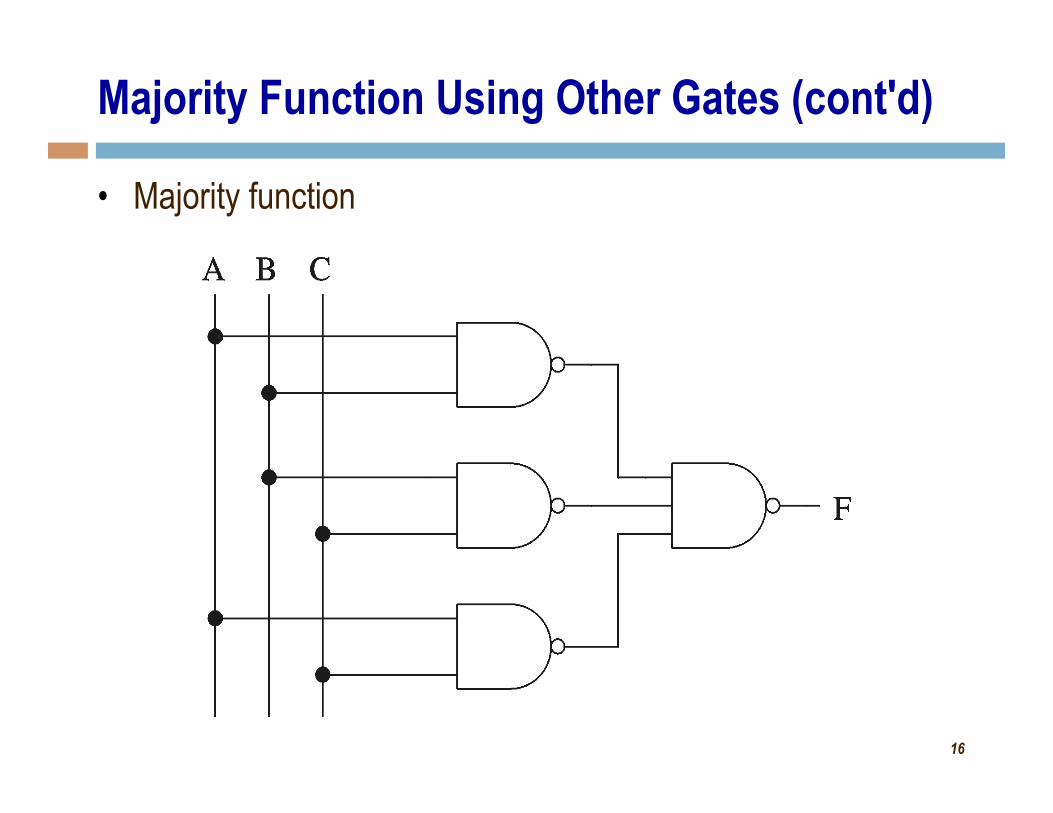
16
Majority Function Using Other Gates (cont'd)
• Majority function
17
Combinational Logic Building Blocks
Some slides modified from: S. Dandamudi, “Fundamentals of Computer Organization and Design”
S. Brown and Z. Vranesic, "Fundamentals of Digital Logic"
18
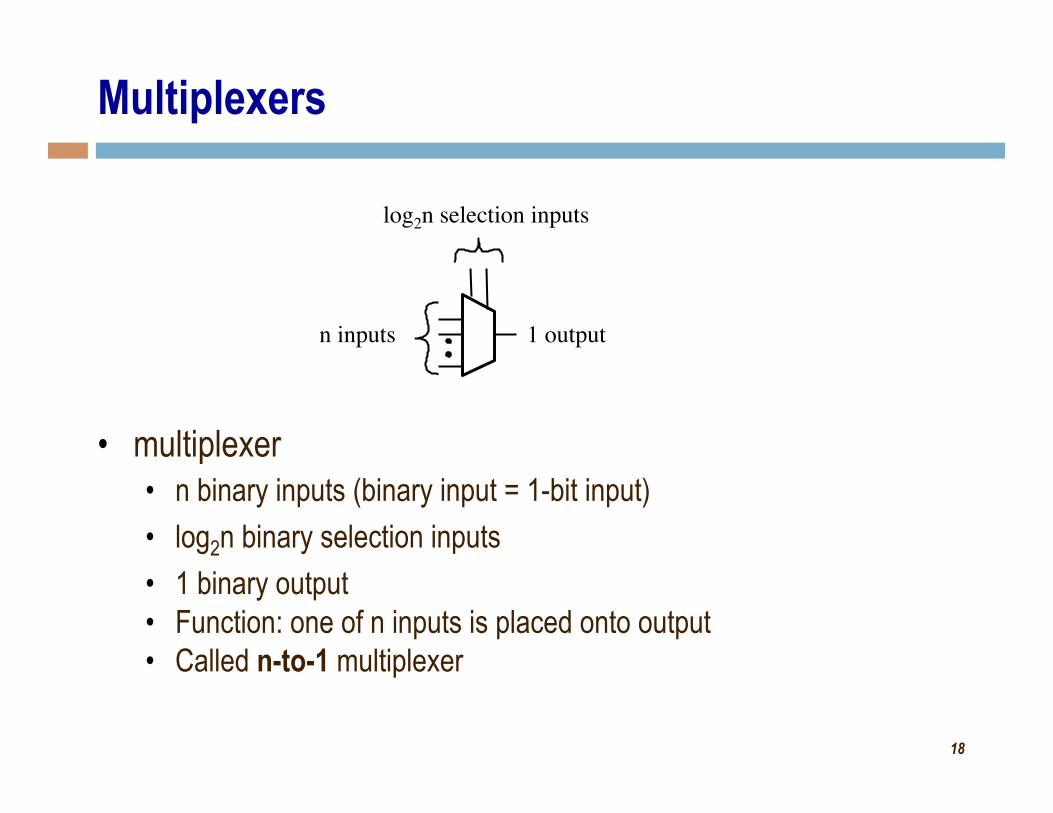
Multiplexers
• multiplexer • n binary inputs (binary input = 1-bit input) • log2n binary selection inputs • 1 binary output • Function: one of n inputs is placed onto output • Called n-to-1 multiplexer
n inputs 1 output
log2n selection inputs
19
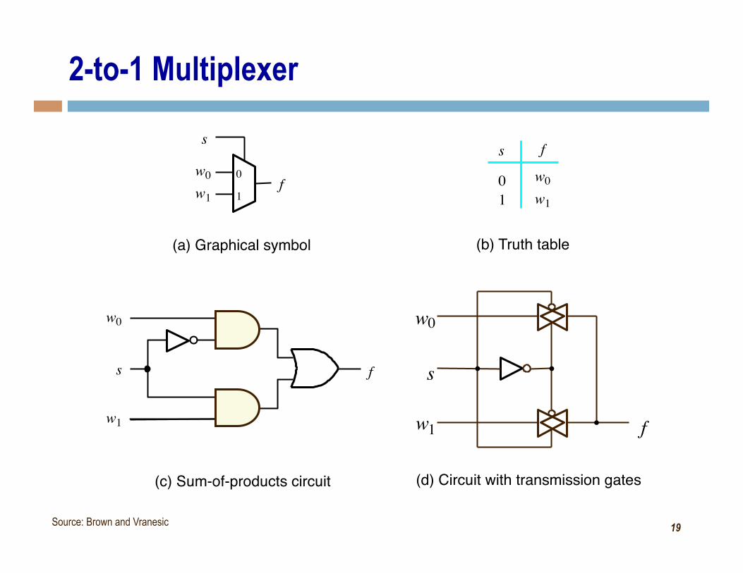
2-to-1 Multiplexer
(a) Graphical symbol
f
s w 0 w 1
0 1
(b) Truth table
0 1
f
f s
w 0
w 1
(c) Sum-of-products circuit
s w 0 w 1
(d) Circuit with transmission gates
w 0
w 1 f
s
Source: Brown and Vranesic
20
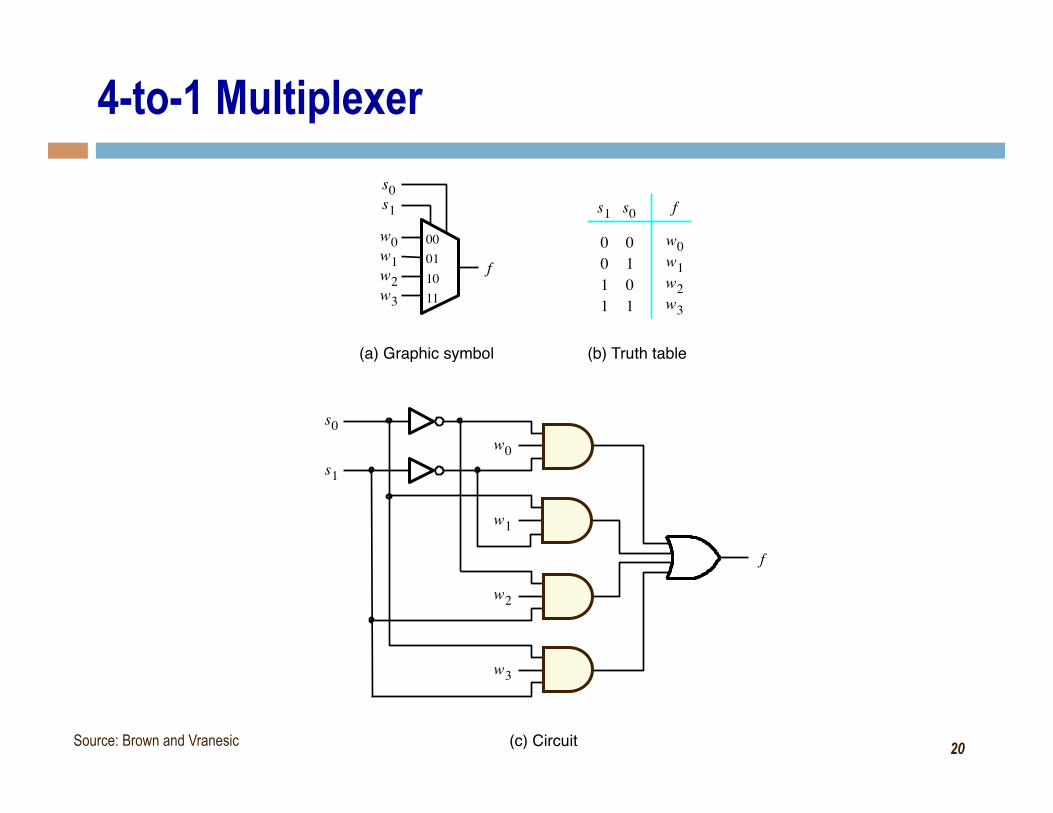
4-to-1 Multiplexer
f
s 1 w 0 w 1
00 01
(b) Truth table
w 0 w 1
s 0
w 2 w 3
10 11
0 0 1 1
1 0 1
f s 1 0 s 0
w 2 w 3
f
(c) Circuit
s 1 w 0
w 1
s 0
w 2
w 3
(a) Graphic symbol
Source: Brown and Vranesic
21
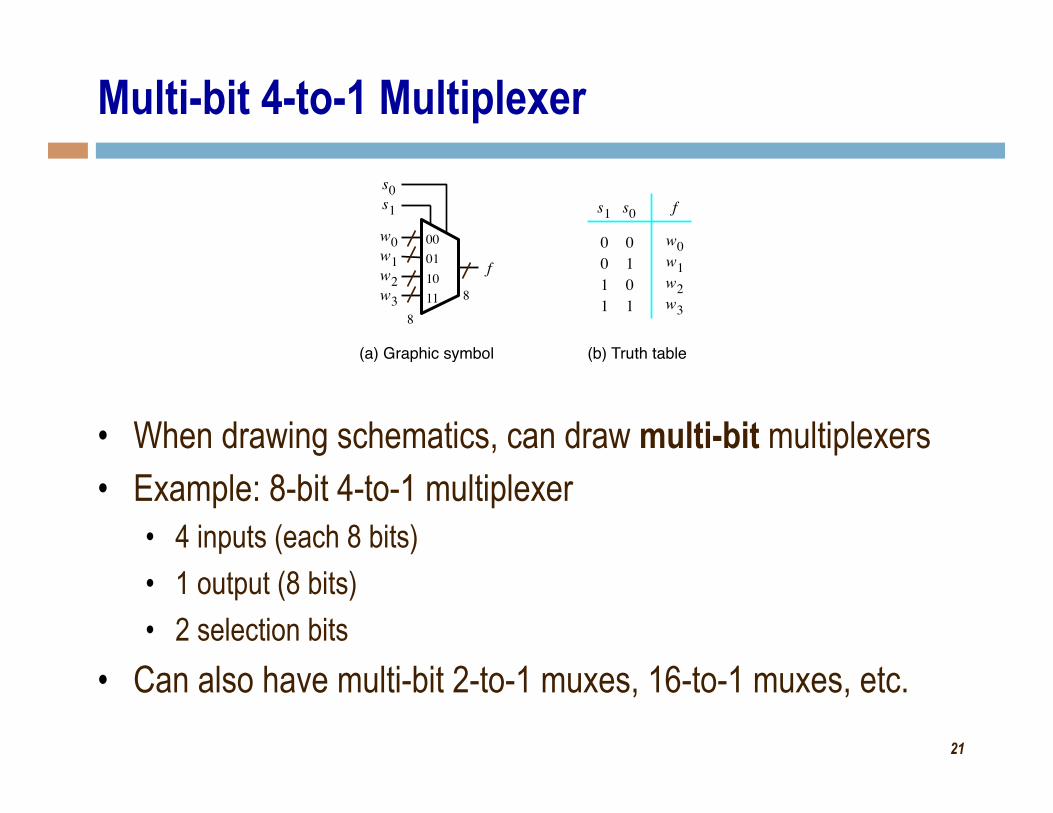
Multi-bit 4-to-1 Multiplexer
• When drawing schematics, can draw multi-bit multiplexers • Example: 8-bit 4-to-1 multiplexer
• 4 inputs (each 8 bits) • 1 output (8 bits) • 2 selection bits
• Can also have multi-bit 2-to-1 muxes, 16-to-1 muxes, etc.
f
s 1 w 0 w 1
00 01
(b) Truth table
w 0 w 1
s 0
w 2 w 3
10 11
0 0 1 1
1 0 1
f s 1 0 s 0
w 2 w 3
(a) Graphic symbol 8
8
22
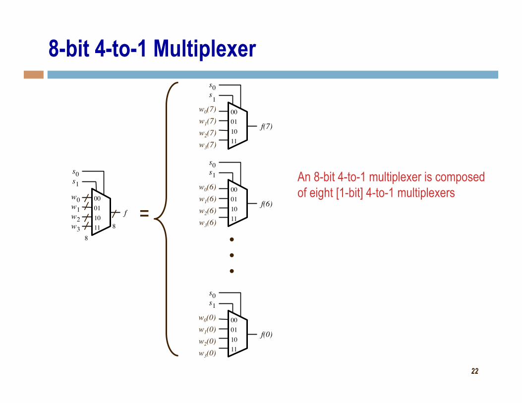
8-bit 4-to-1 Multiplexer
f(7)
s 1
00 01
s 0
10 11
f(6)
s 1 00 01
s 0
10 11
f(0)
s 1 00 01
s 0
10 11
w0(7) w1(7) w2(7) w3(7)
w0(6) w1(6) w2(6) w3(6)
w0(0) w1(0) w2(0) w3(0)
An 8-bit 4-to-1 multiplexer is composed of eight [1-bit] 4-to-1 multiplexers
f
s 1 w 0 w 1
00 01
s 0
w 2 w 3
10 11
8 8 =
23
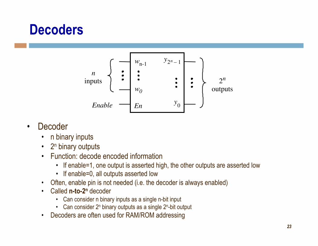
Decoders
• Decoder • n binary inputs • 2n binary outputs • Function: decode encoded information
• If enable=1, one output is asserted high, the other outputs are asserted low • If enable=0, all outputs asserted low
• Often, enable pin is not needed (i.e. the decoder is always enabled) • Called n-to-2n decoder
• Can consider n binary inputs as a single n-bit input • Can consider 2n binary outputs as a single 2n-bit output
• Decoders are often used for RAM/ROM addressing
n-1
w 0
n inputs
En Enable
2 n outputs
y 0
w y 2 n 1 –
24
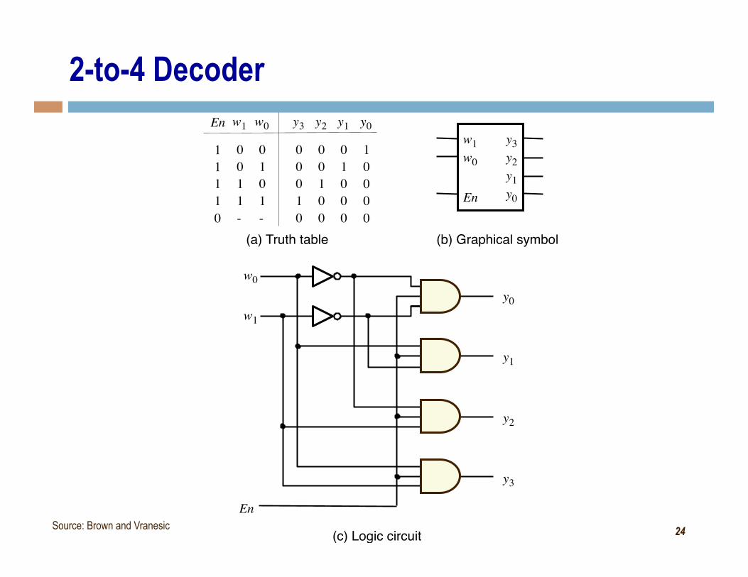
2-to-4 Decoder
0 0 1 1
1 0 1
y 3 w 1 0
w 0
(c) Logic circuit
w 1
w 0
- -
1 1
0 1 1
En
0 0 1
0
0
y 2
0 1 0
0
0
y 1
1 0 0
0
0
y 0
0 0 0
1
0
y 0
y 1
y 2
y 3 En
w 1
En
y 3 w 0 y 2
y 1 y 0
(a) Truth table (b) Graphical symbol
Source: Brown and Vranesic
25
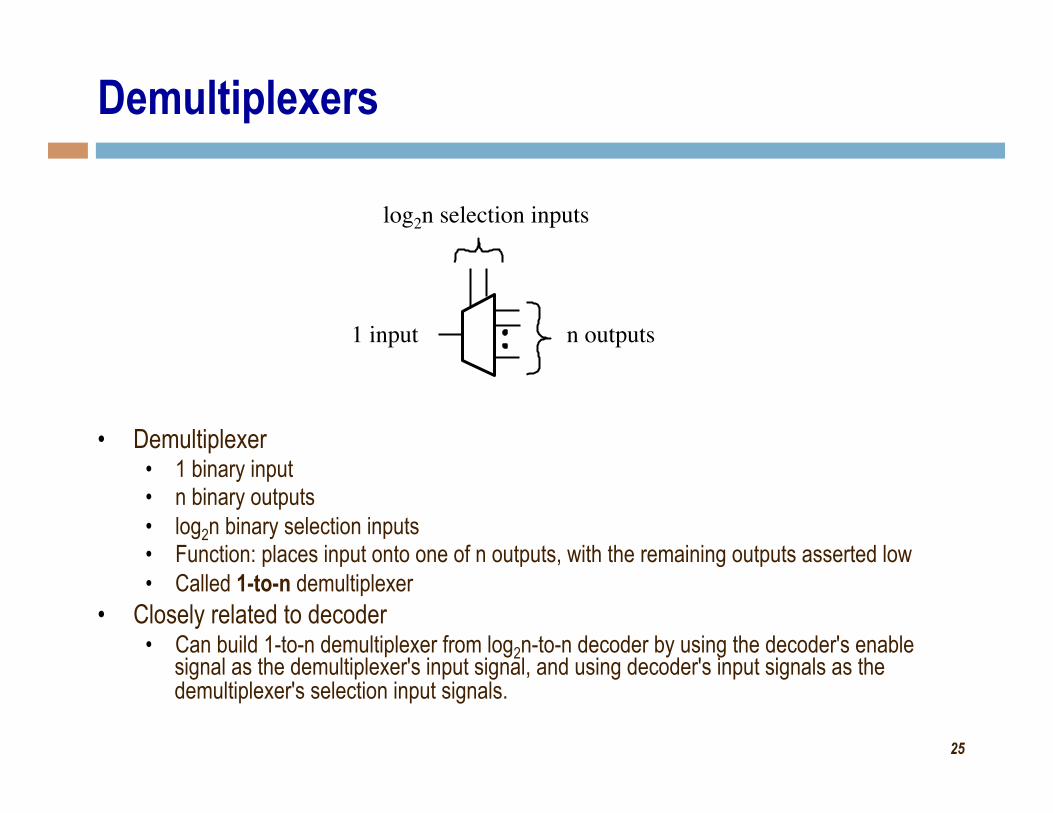
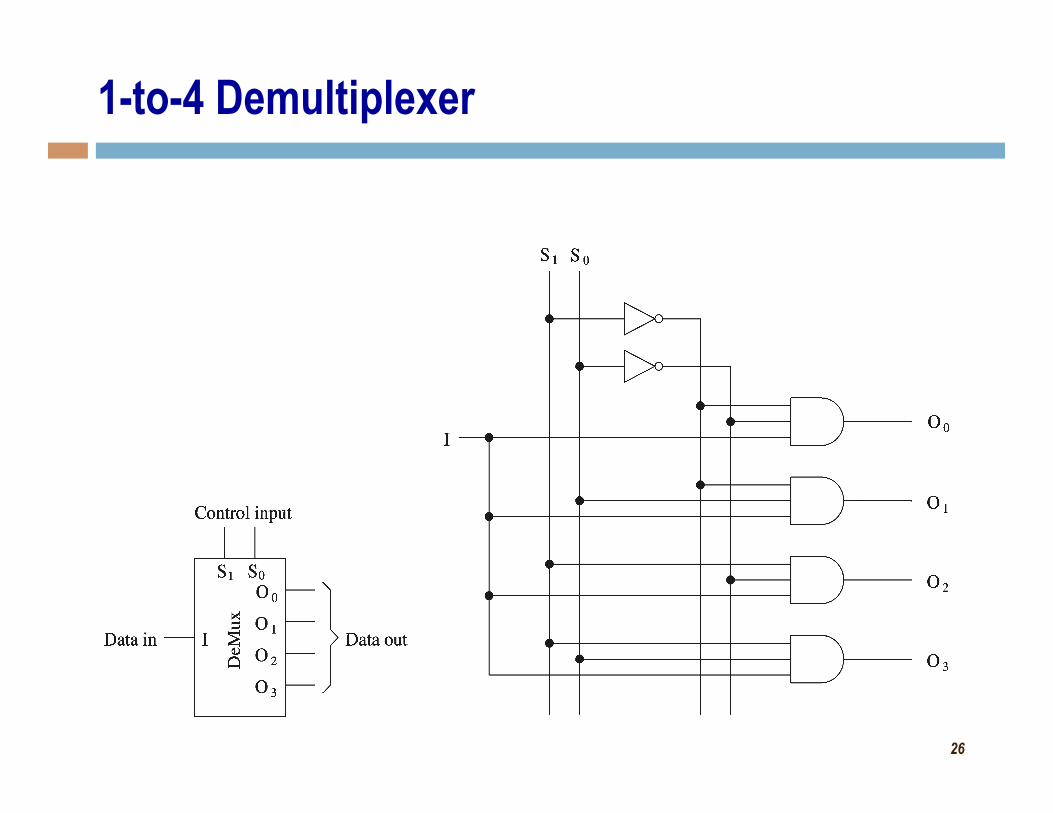
Demultiplexers
• Demultiplexer • 1 binary input • n binary outputs • log2n binary selection inputs • Function: places input onto one of n outputs, with the remaining outputs asserted low • Called 1-to-n demultiplexer
• Closely related to decoder • Can build 1-to-n demultiplexer from log2n-to-n decoder by using the decoder's enable
signal as the demultiplexer's input signal, and using decoder's input signals as the demultiplexer's selection input signals.
n outputs 1 input
log2n selection inputs
26
1-to-4 Demultiplexer
27
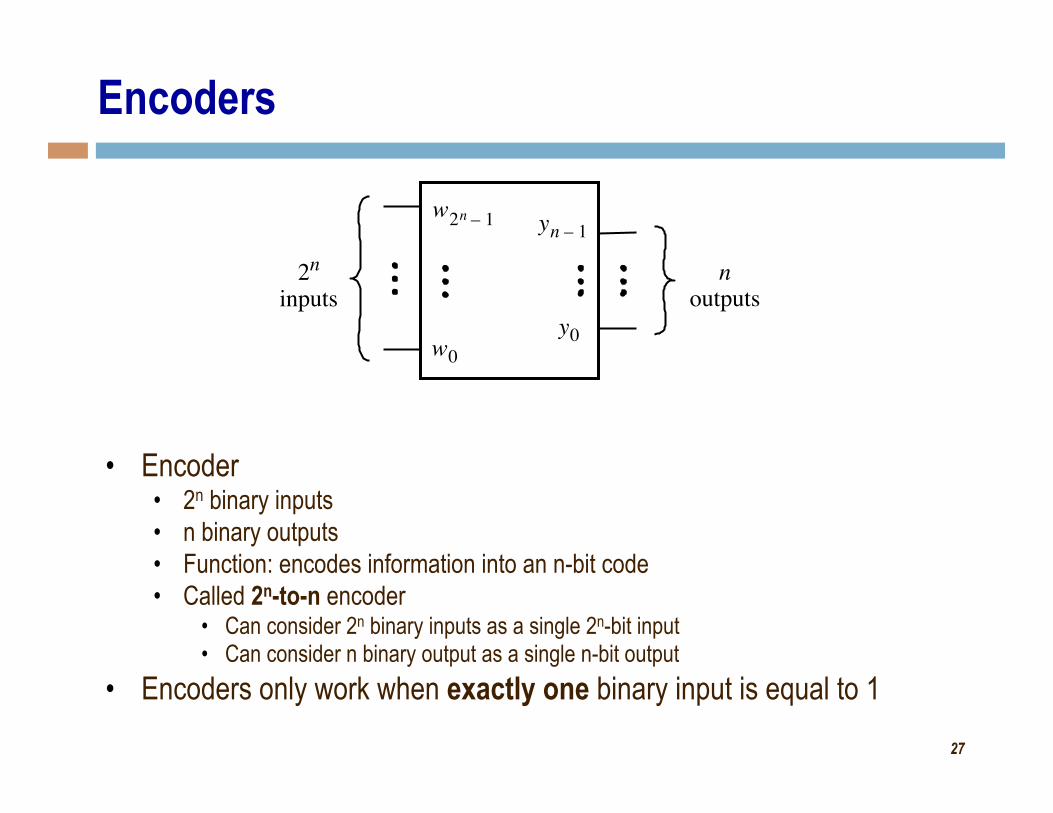
Encoders
2 n inputs
w 0 y 0
y n 1 – n
outputs
• Encoder • 2n binary inputs • n binary outputs • Function: encodes information into an n-bit code • Called 2n-to-n encoder
• Can consider 2n binary inputs as a single 2n-bit input • Can consider n binary output as a single n-bit output
• Encoders only work when exactly one binary input is equal to 1
w 2 n 1 –
28
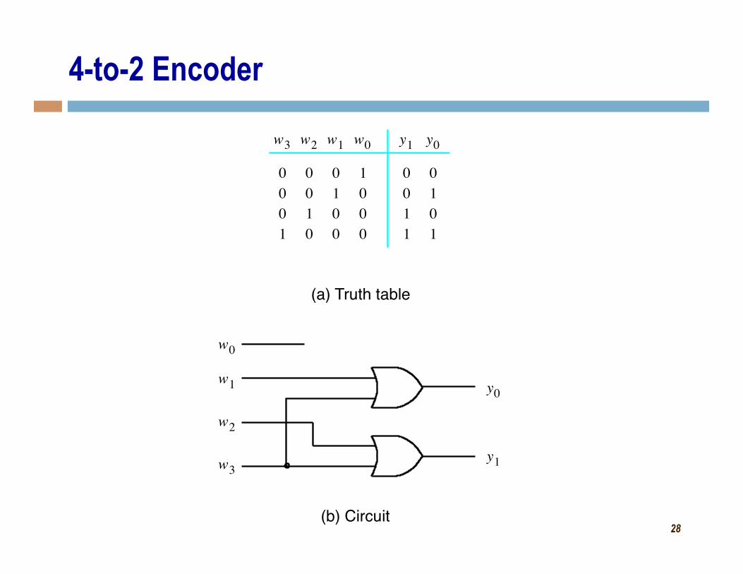
4-to-2 Encoder
0 0 1 1
1 0 1
w 3 y 1 0 y 0
(b) Circuit
w 1
w 0
0 0 1
0 w 2
0 1 0
0 w 1
1 0 0
0 w 0
0 0 0
1
y 0 w 2
w 3 y 1
(a) Truth table
29
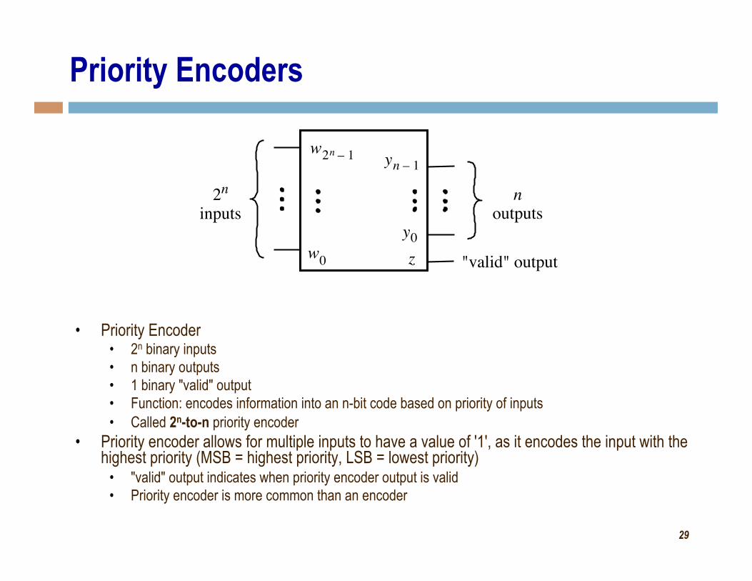
Priority Encoders
2 n inputs
w 0
w 2 n 1 –
y 0
y n 1 – n
outputs
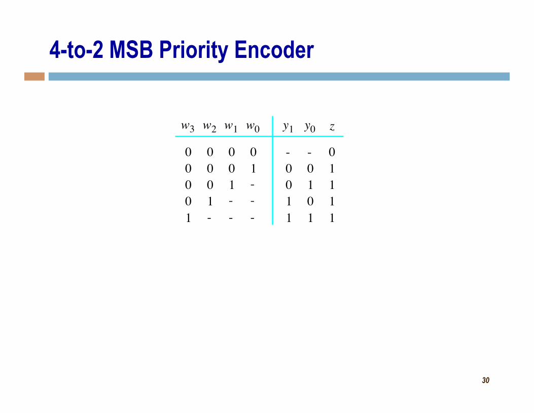
• Priority Encoder • 2n binary inputs • n binary outputs • 1 binary "valid" output • Function: encodes information into an n-bit code based on priority of inputs • Called 2n-to-n priority encoder
• Priority encoder allows for multiple inputs to have a value of '1', as it encodes the input with the highest priority (MSB = highest priority, LSB = lowest priority)
• "valid" output indicates when priority encoder output is valid • Priority encoder is more common than an encoder
z "valid" output
30
4-to-2 MSB Priority Encoder
- 0 0 1
0 1 0
w 0 y 1 -
y 0
1 1
0 1
1
1 1
z
1 - -
0
-
w 1
0 1 -
0
-
w 2
0 0 1
0
-
w 3
0 0 0
0
1
31
Single-Bit Adders
• Half-adder • Adds two binary (i.e. 1-bit) inputs A and B
• Produces a sum and carryout • Problem: Cannot use it alone to build larger adders
• Full-adder • Adds three binary (i.e. 1-bit) inputs A, B, and carryin
• Like half-adder, produces a sum and carryout • Allows building M-bit adders (M > 1)
• Simple technique • Connect Cout of one adder to Cin of the next
• These are called ripple-carry adders
32
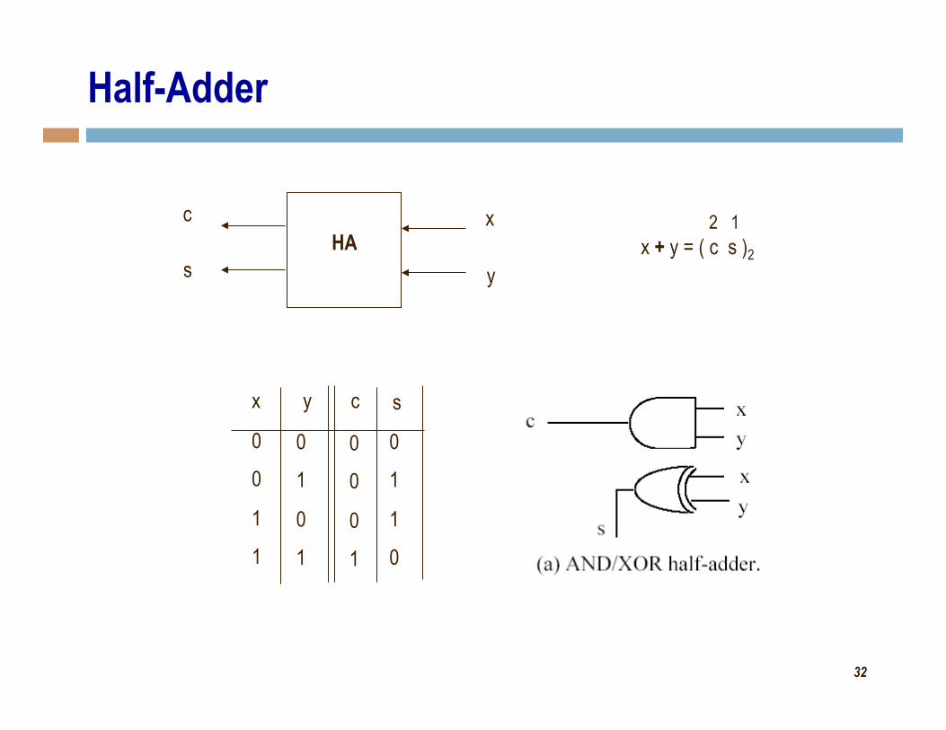
Half-Adder
x
y
c
s HA x + y = ( c s )2
2 1
x y c s
0
0
1
1
0
1
0
1
0
0
0
1
0
1
1
0
33
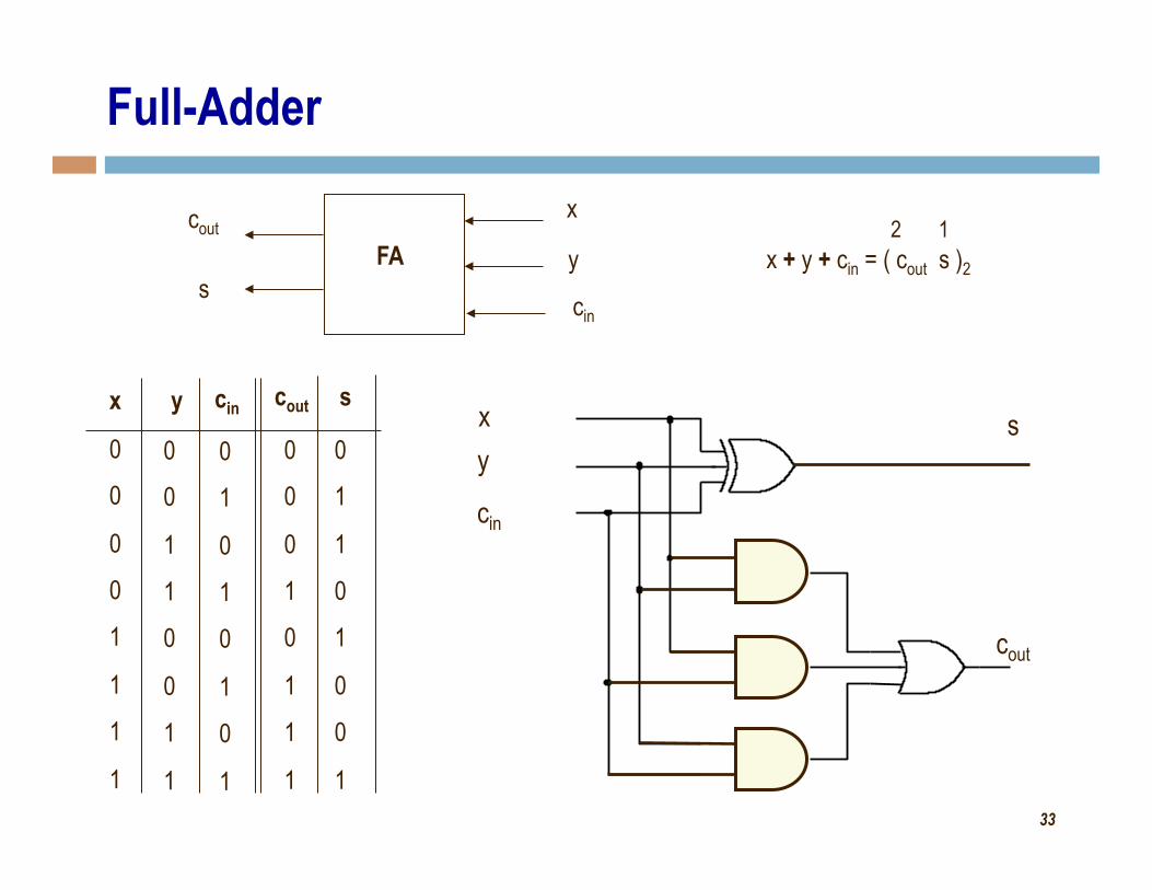
Full-Adder x
y cout
s FA x + y + cin = ( cout s )2
2 1
x y cout s
0
0
0
0
1
1
1
1
0
0
1
1
0
0
1
1
0
0
0
1
0
1
1
1
0
1
1
0
1
0
0
1
cin
0
1
0
1
0
1
0
1
cin x y
cin
s
cout
34
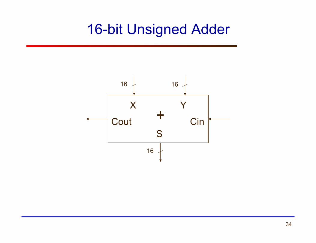
16-bit Unsigned Adder
16 16
X Y
16
Cin Cout S
+
35
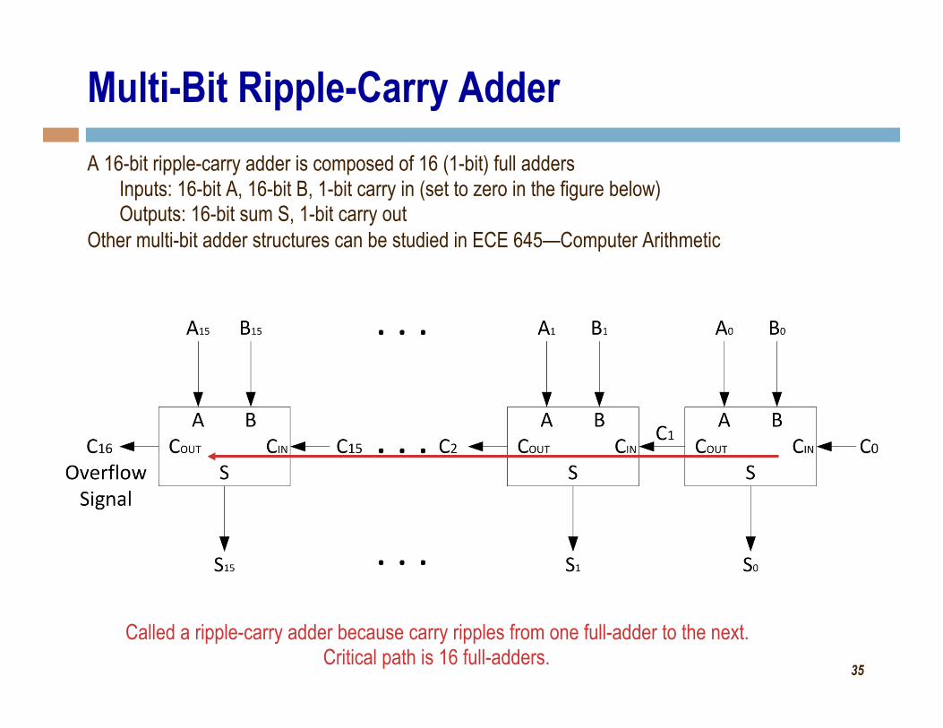
Multi-Bit Ripple-Carry Adder A 16-bit ripple-carry adder is composed of 16 (1-bit) full adders
Inputs: 16-bit A, 16-bit B, 1-bit carry in (set to zero in the figure below) Outputs: 16-bit sum S, 1-bit carry out
Other multi-bit adder structures can be studied in ECE 645—Computer Arithmetic
Called a ripple-carry adder because carry ripples from one full-adder to the next. Critical path is 16 full-adders.
36
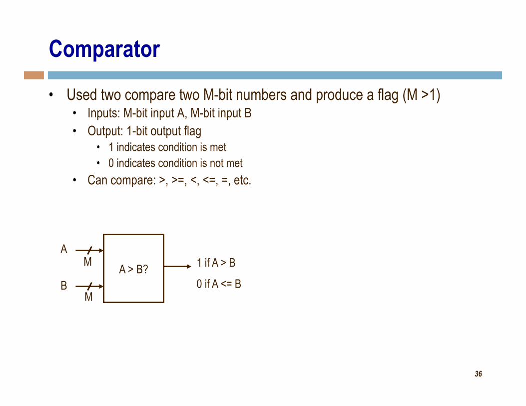
Comparator
• Used two compare two M-bit numbers and produce a flag (M >1) • Inputs: M-bit input A, M-bit input B • Output: 1-bit output flag
• 1 indicates condition is met • 0 indicates condition is not met
• Can compare: >, >=, <, <=, =, etc.
A > B? A
B
1 if A > B
0 if A <= B
M
M
37
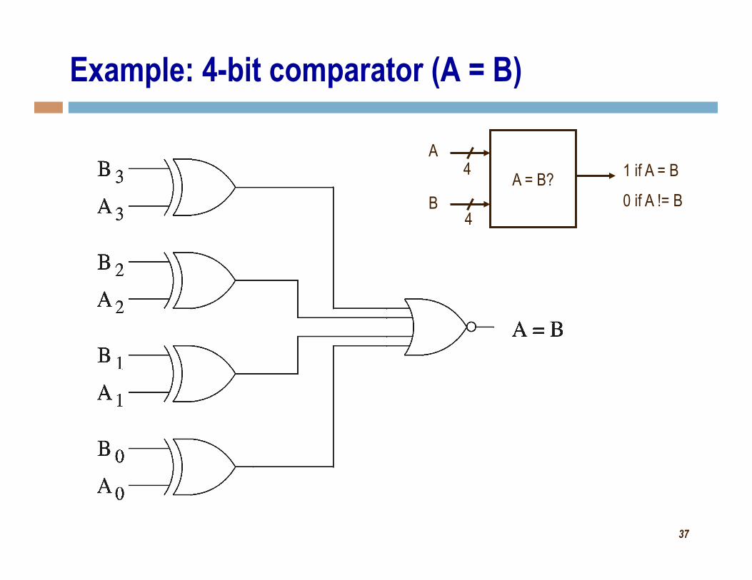
Example: 4-bit comparator (A = B)
A = B? A
B
1 if A = B
0 if A != B
4
4
38
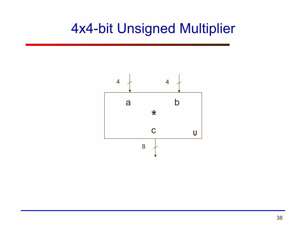
4x4-bit Unsigned Multiplier
4 4
a b
8
c*
U
39
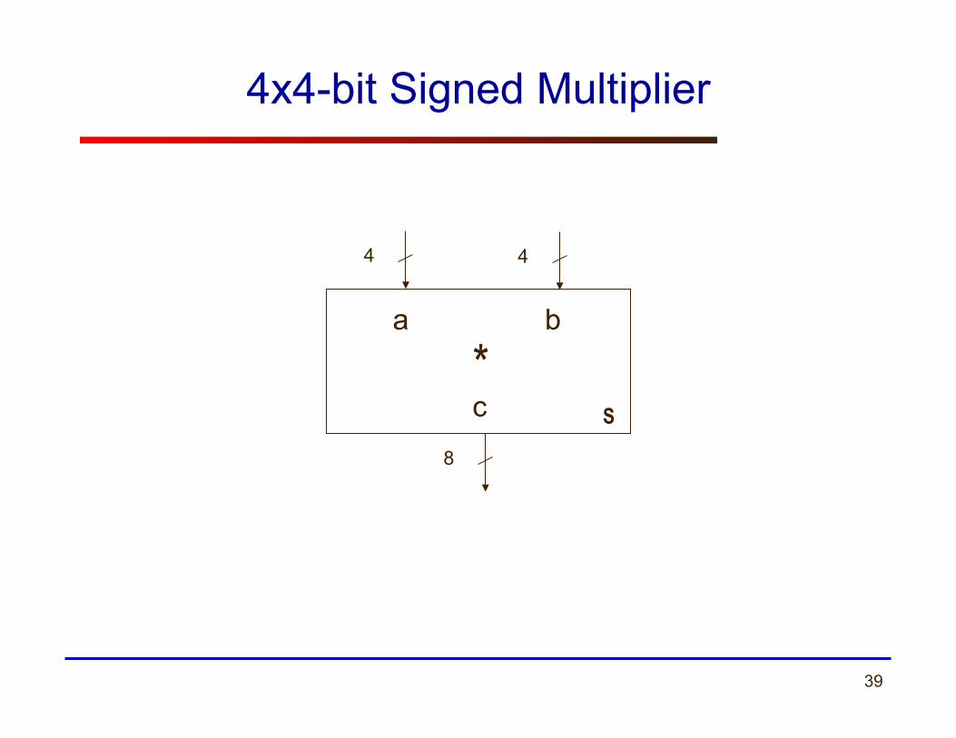
4x4-bit Signed Multiplier
4 4
a b
8
c S
*
40
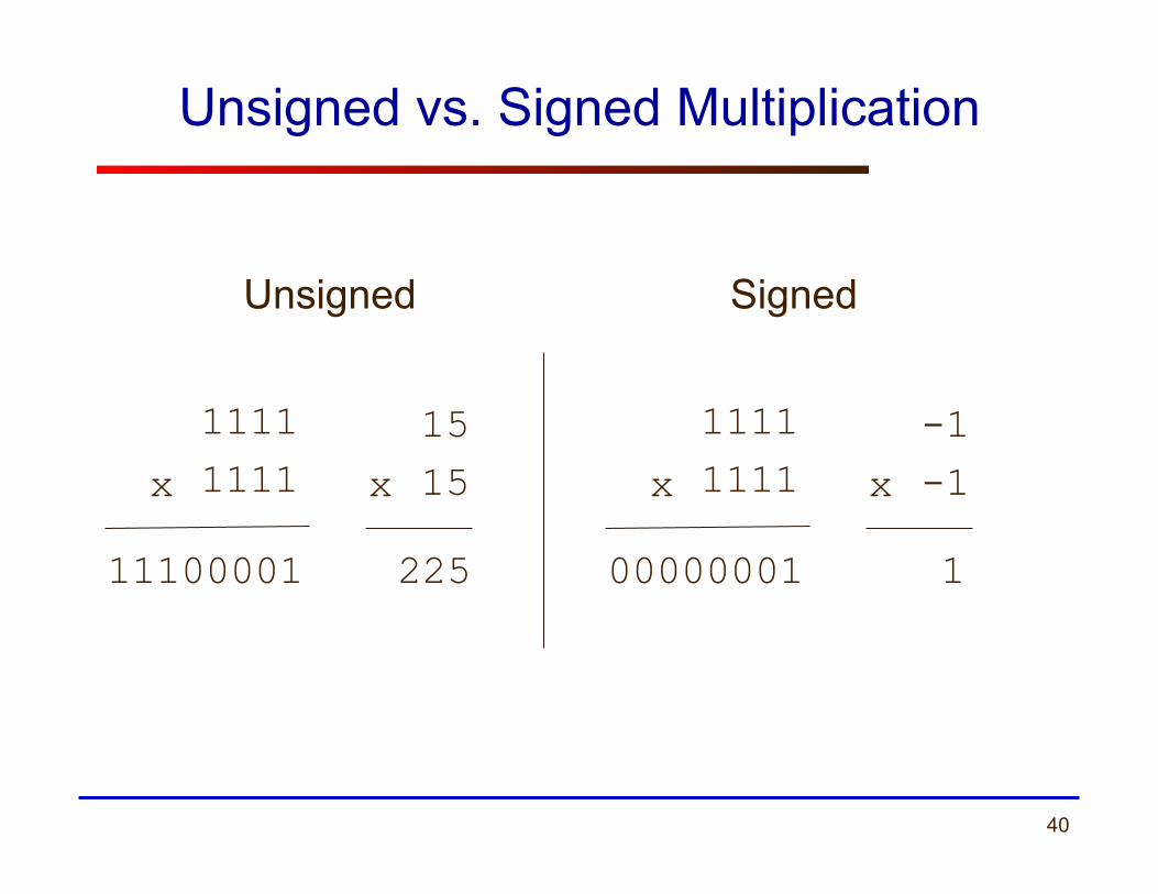
Unsigned vs. Signed Multiplication
1111 1111 x
11100001
15 15 x
225
1111 1111 x
00000001
-1 -1 x
1
Unsigned Signed
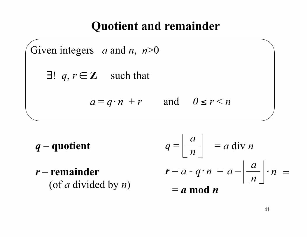
Quotient and remainder
Given integers a and n, n>0
∃! q, r ∈ Z such that a = q⋅ n + r and 0 ≤ r < n
q – quotient r – remainder (of a divided by n)
q = a n = a div n
r = a - q⋅ n = a – a n ⋅ n =
= a mod n
41
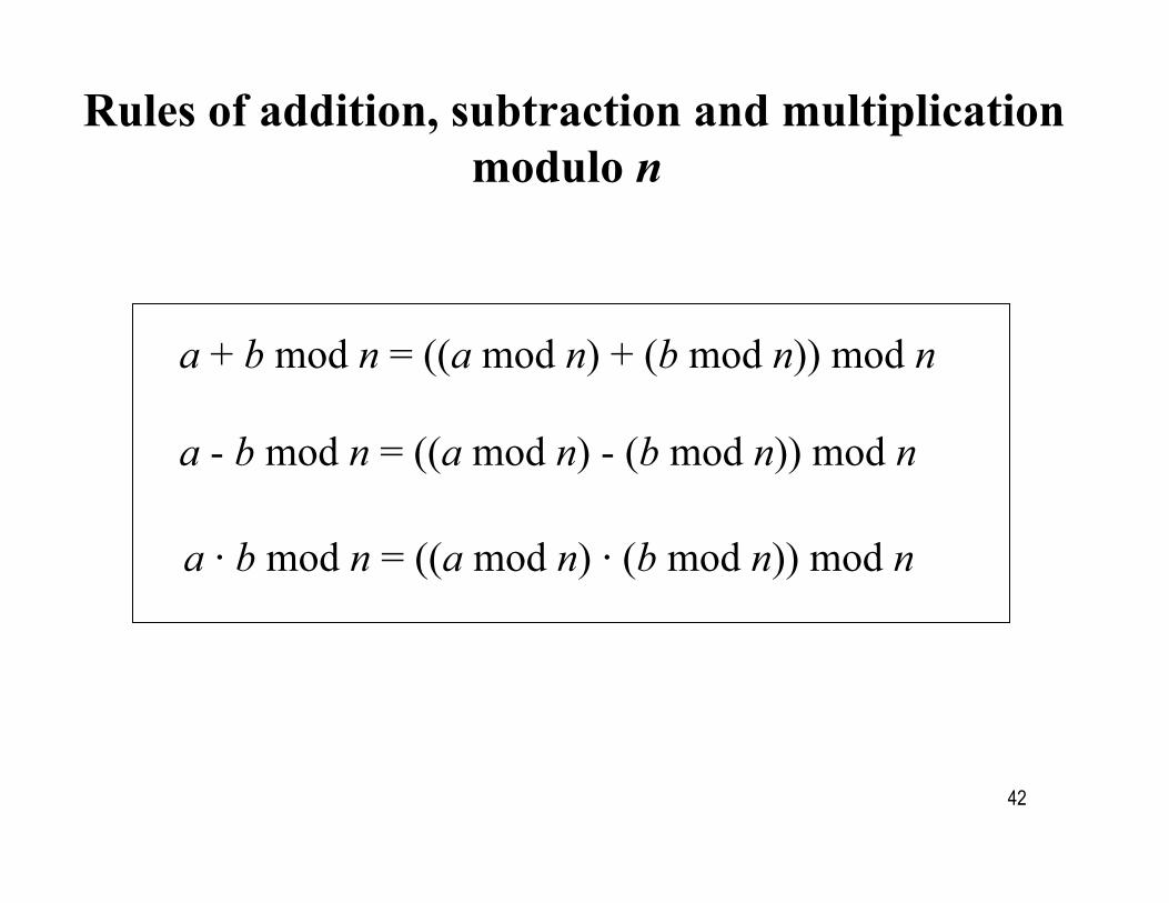
Rules of addition, subtraction and multiplication modulo n
a + b mod n = ((a mod n) + (b mod n)) mod n
a - b mod n = ((a mod n) - (b mod n)) mod n
a ⋅ b mod n = ((a mod n) ⋅ (b mod n)) mod n
42
43
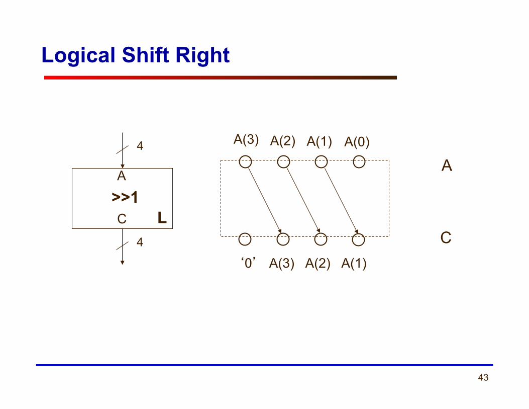
Logical Shift Right
A(3) A(2) A(1) A(0)
‘0’ A(3) A(2) A(1)
A
C
4
4
A
C >>1
L
44
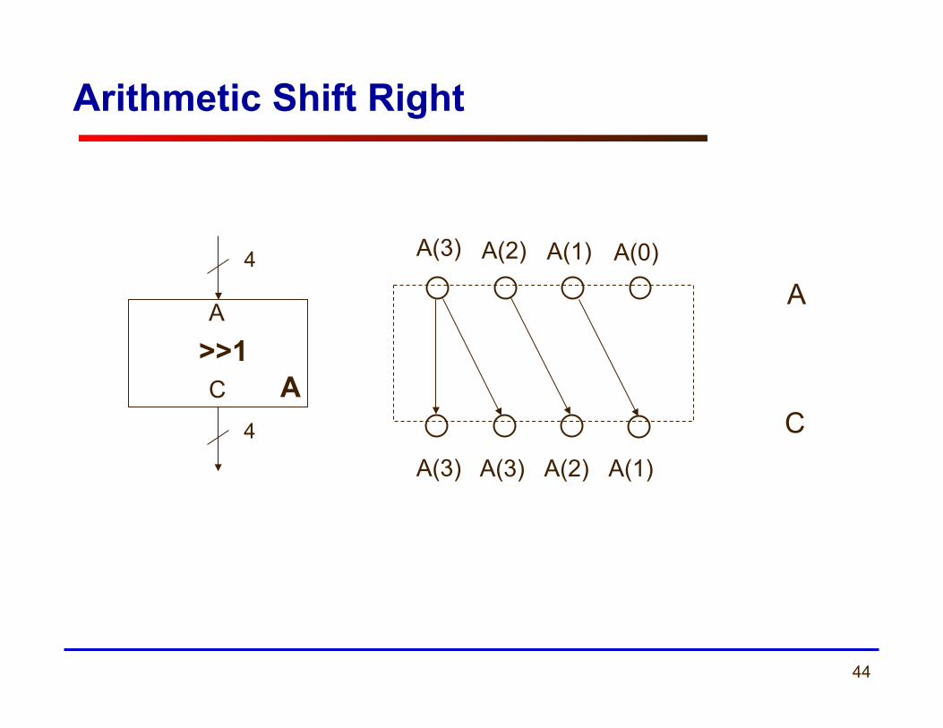
Arithmetic Shift Right
A(3) A(2) A(1) A(0)
A(3) A(2) A(1)
A
C
4
4
A
C >>1
A(3)
A
45
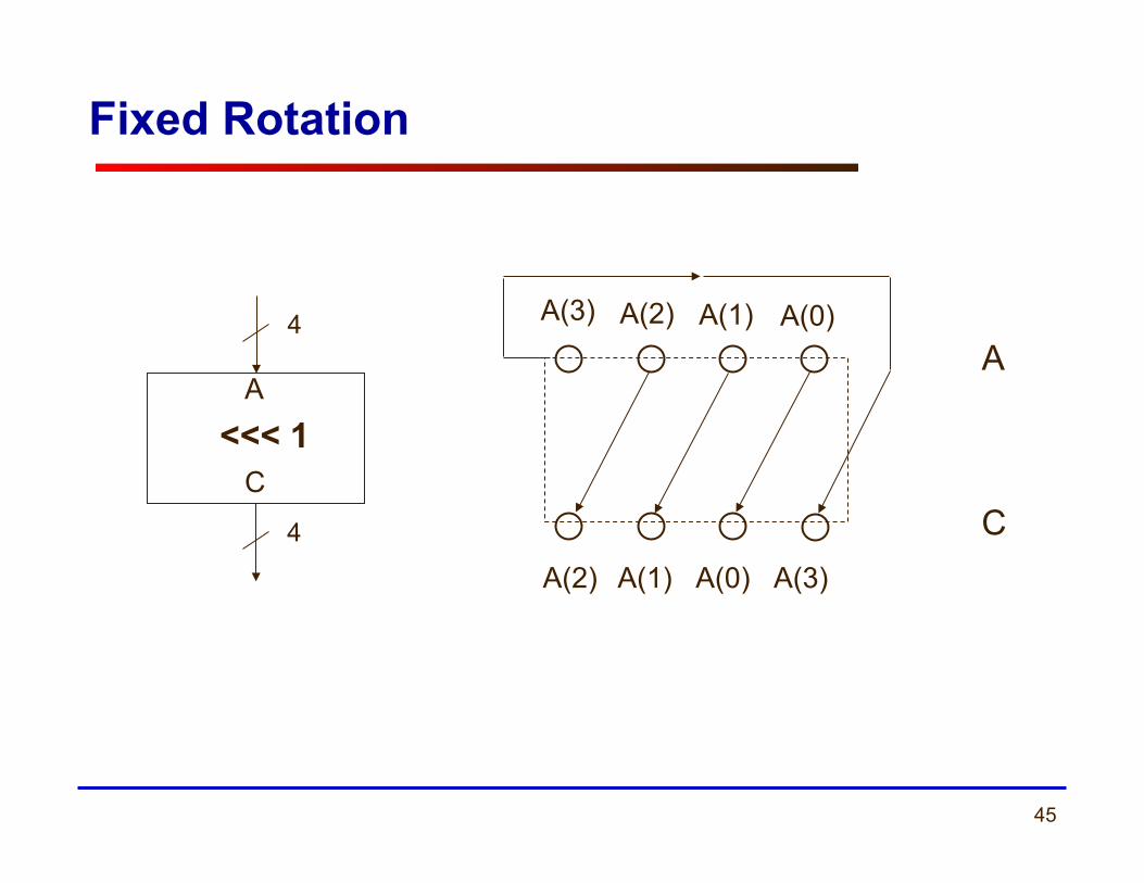
Fixed Rotation
A(3) A(2) A(1) A(0)
A(2) A(1) A(0) A(3)
A 4
4
A
C <<< 1
C
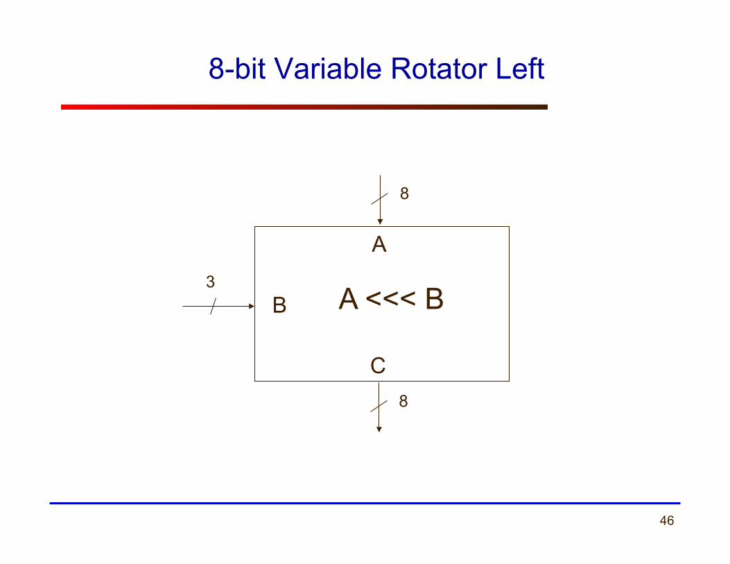
46
8-bit Variable Rotator Left
8
8
3
A
B
C
A <<< B
47
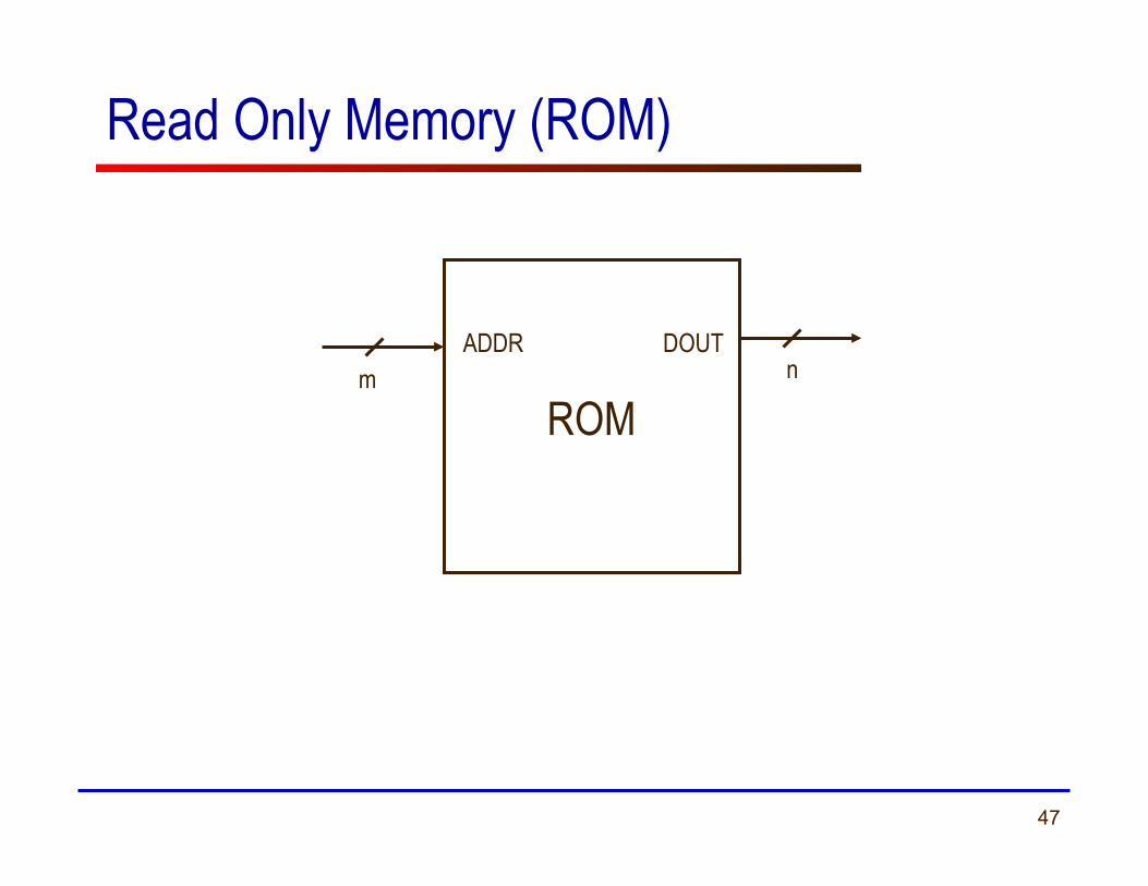
Read Only Memory (ROM)
ROM
ADDR DOUT m n
48
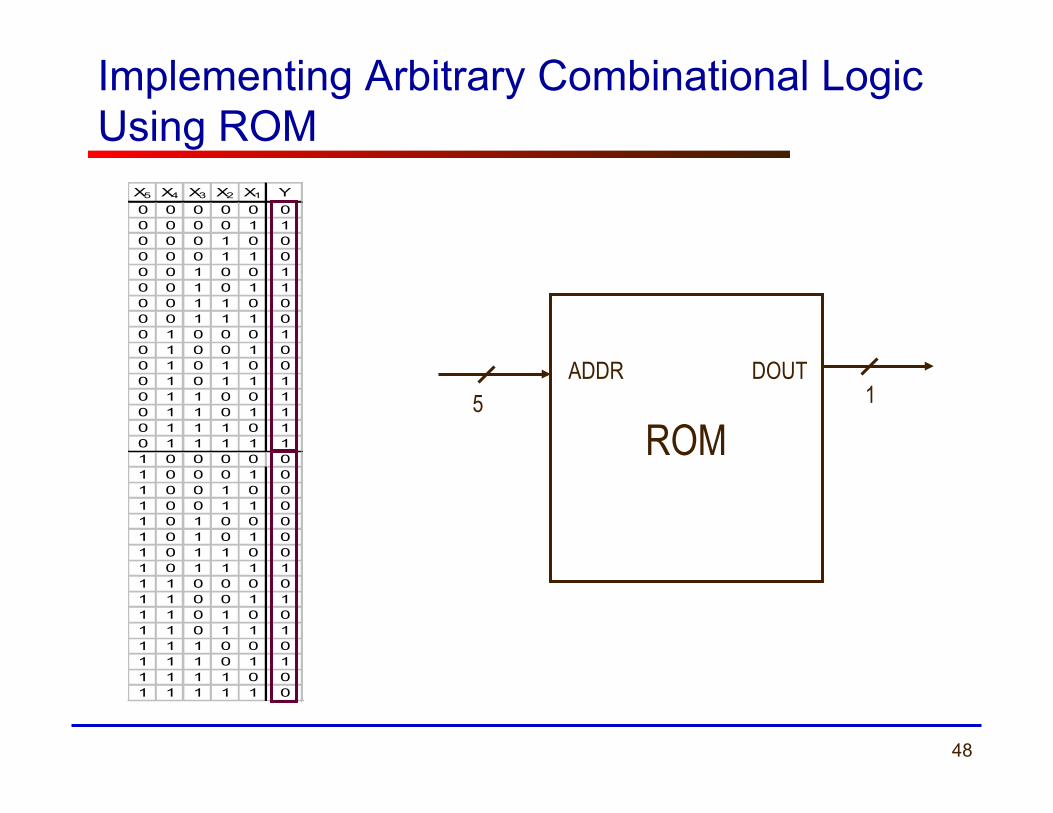
Implementing Arbitrary Combinational Logic Using ROM
X5 X4 X3 X2 X1 Y0 0 0 0 0 00 0 0 0 1 10 0 0 1 0 00 0 0 1 1 00 0 1 0 0 10 0 1 0 1 10 0 1 1 0 00 0 1 1 1 00 1 0 0 0 10 1 0 0 1 00 1 0 1 0 00 1 0 1 1 10 1 1 0 0 10 1 1 0 1 10 1 1 1 0 10 1 1 1 1 11 0 0 0 0 01 0 0 0 1 01 0 0 1 0 01 0 0 1 1 01 0 1 0 0 01 0 1 0 1 01 0 1 1 0 01 0 1 1 1 11 1 0 0 0 01 1 0 0 1 11 1 0 1 0 01 1 0 1 1 11 1 1 0 0 01 1 1 0 1 11 1 1 1 0 01 1 1 1 1 0
ROM
ADDR DOUT 5 1
49
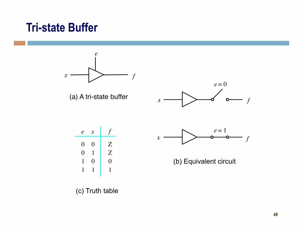
(b) Equivalent circuit
(c) Truth table
x f
e
(a) A tri-state buffer
0 0 1 1
0 1 0 1
Z Z 0 1
f e x
x f
e = 0
e = 1 x f
Tri-state Buffer
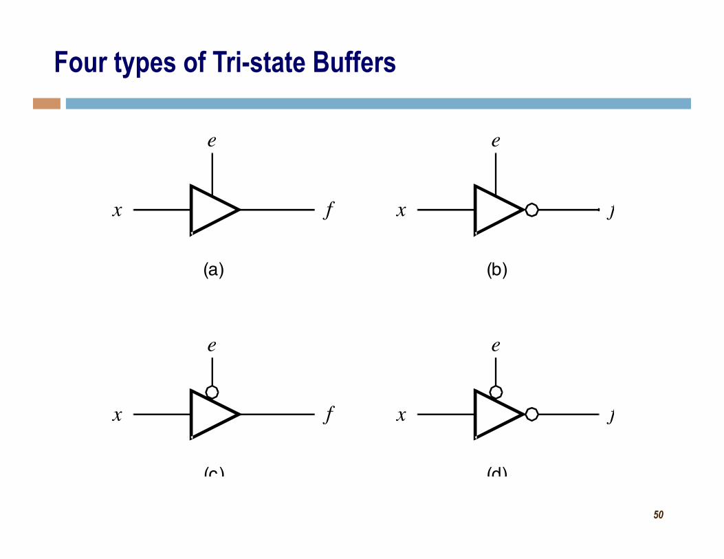
50
x f
e
(b)
x f
e
(a)
x f
e
(c)
x f
e
(d)
Four types of Tri-state Buffers