Embed Size (px)
Citation preview
Translation of original instructions
EB 8355-2 EN
Edition October 2018
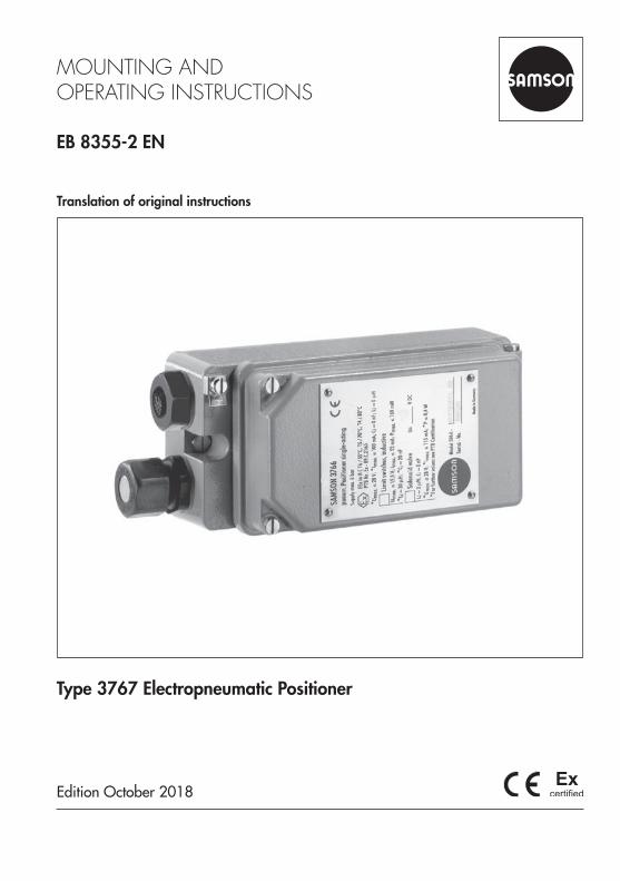
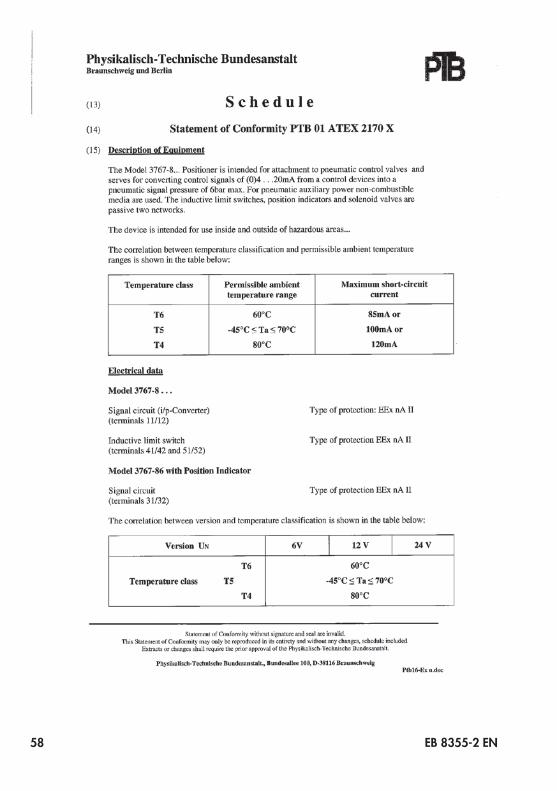
Type 3767 Electropneumatic Positioner
Note on these mounting and operating instructions
These mounting and operating instructions assist you in mounting and operating the device safely. The instructions are binding for handling SAMSON devices.
Î For the safe and proper use of these instructions, read them carefully and keep them for later reference.
Î If you have any questions about these instructions, contact SAMSON‘s After-sales Service Department ([email protected]).
The mounting and operating instructions for the devices are included in the scope of delivery. The latest documentation is available on our website at www.samson.de > Service & Support > Downloads > Documentation.
Definition of signal words
Hazardous situations which, if not avoided, will result in death or serious injury
Hazardous situations which, if not avoided, could result in death or serious injury
Property damage message or malfunction
Additional information
Recommended action
DANGER!
WARNING!
NOTICE!
Note
Tip
2 EB 8355-2 EN
Contents
EB 8355-2 EN 3
1 General safety instructions .............................................................................52 Design and principle of operation ..................................................................62.1 Versions and article code ................................................................................92.2 Technical data .............................................................................................102.3 Additional equipment ...................................................................................112.4 Summary of explosion protection approvals ...................................................123 Mounting on control valves ..........................................................................133.1 DirectattachmenttoType 3277Actuator .......................................................133.2 AttachmentaccordingtoIEC 60534-6 ...........................................................193.2.1 Mounting sequence ......................................................................................203.2.2 Initial adjustment of travel .............................................................................203.3 Attachment to rotary actuators ......................................................................233.3.1 Mounting the lever with feeler roll ..................................................................243.3.2 Mounting the intermediate piece ...................................................................243.3.3 Basic setting of the cam disk .........................................................................263.3.4 Reversingamplifierfordouble-actingactuators ..............................................304 Connections ................................................................................................324.1 Pneumatic connections..................................................................................324.1.1 Pressure gauges ...........................................................................................324.1.2 Supply pressure ...........................................................................................324.2 Electrical connections ...................................................................................344.2.1 Switchingamplifier ......................................................................................354.2.2 Accessories .................................................................................................365 Operation ...................................................................................................375.1 Tuningthepositionermountedontothecontrolvalve .......................................375.1.1 AdjustingtheproportionalbandXpandairdeliveryQ ..................................385.1.2 Settingsforactuatorwith“actuatorstemextends”fail-safeaction .....................395.1.3 Settingsforactuatorwith“actuatorstemretracts”fail-safeaction .....................395.2 Changingtheoperatingdirection ..................................................................405.3 Adjustingthelimitcontacts ...........................................................................415.4 Adjustingthepositiontransmitter...................................................................43
Contents
4 EB 8355-2 EN
6 Upgrading and retrofitting the positioner......................................................466.1 Convertingfromelectropneumatictopneumatic .............................................466.2 Installingthelimitcontacts ............................................................................476.3 Installingasolenoidvalve .............................................................................476.4 Removingthesolenoidvalve .........................................................................487 Servicing explosion-protected devices ..........................................................488 Dimensions in mm .......................................................................................49
EB 8355-2 EN 5
General safety instructions
1 General safety instructionsFor your own safety, follow these instructions concerning the mounting, start up and opera-tion of the device: − The device is to be mounted, started up or operated only by trained and experienced
personnel familiar with the product. According to these mounting and operating instruc-tions, trained personnel refers to individuals who are able to judge the work they are as-signed to and recognize possible dangers due to their specialized training, their knowl-edge and experience as well as their knowledge of the applicable standards.
− Any hazards that could be caused in the valve by the process medium, the signal pres-sure or by moving parts are to be prevented by taking appropriate precautions.If inadmissible motions or forces are produced in the pneumatic actuator as a result of the supply pressure level, it must be restricted using a suitable supply pressure reducing station.
− Explosion-protected versions of this device are to be operated only by personnel who has undergone special training or instructions or who is authorized to work on explosion-pro-tecteddevicesinhazardousareas.Seesection7.
To avoid damage to any equipment, the following also applies: − Proper shipping and storage are assumed.
The device with a CE marking fulfills the requirements of the Directive 2014/34/EU and the Directive 2014/30/EU. The declarations of conformity are included at the end of these in-structions.
Note
6 EB 8355-2 EN
Design and principle of operation
2 Design and principle of oper-ation
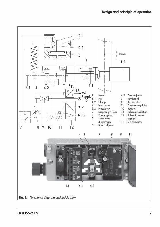
The positioner consists of an electropneumat-ic converter and a pneumatic unit equipped with a lever for travel pick-up, a measuring diaphragm and the pneumatic control system withnozzle,diaphragmlever(flapperplate)and booster.The positioner is designed either for direct at-tachmenttoSAMSONType 3277Actua-tors or for attachment to actuators according to NAMUR (IEC 60534-6) using an adapt-er housing.The positioner can be additionally equipped with either inductive limit contacts and/or a solenoid valve or position transmitter.Thecontrolsignal,e.g.4to20 mA,issuedbythe controller is transmitted to the electropneu-matic converter (13) where it is converted into a proportional pressure signal pe.The positioner operates according to the force-balance principle. The valve travel, i.e. the valve position, is transmitted to the pick-up lever (1) over the pin (1.1) and determines the force of the range spring (4). This force is compared to the positioning force generat-ed by the pressure pe at the measuring dia-phragm(5).If either the control signal or the valve posi-tion changes, the diaphragm lever (3) moves, altering the distance to the nozzle (2.1 or 2.2), depending on the adjusted direction of action of the positioner.The supply air is supplied to the booster (10) and the pressure regulator (9).
ThecontrolledsupplyairflowsthroughtheXp restriction (8) and the nozzle (2.1, 2.2) and hitsthediaphragmlever(flapperplate).Any change in the reference variable or the valve position causes the pressure to change upstream or downstream of the booster.The air controlled by the booster (signal pres-sure pst)flowsthroughthevolumerestriction(11) to the pneumatic actuator, causing the plug stem to move to a position correspond-ing to the reference variable.TheadjustableXp restriction (8) and volume restriction (11) are used to optimize the posi-tioner control loop.The pick-up lever (1) and the range spring (4) must be selected to match the rated valve travel and the nominal span of the reference variable.
Positioner with inductive limit contactsIn this version, the rotary shaft of the position-er carries two adjustable tags which actuate the built-in proximity switches.
Positioner with solenoid valveWhen the positioner is equipped with a solenoid valve, the valve can be moved to the fail-safe position, regardless of the positioner's output signal. If a control signal corresponding to the binary signal '0' (OFF) is applied to the input, the signal pressure pst is shut off and the actuator is vented. The actuator springs move the valve to its fail-safe position.
EB 8355-2 EN 7
Design and principle of operation
1 Lever1.1 Pin1.2 Clamp2.1 Nozzle >>2.2 Nozzle <>3 Diaphragm lever4 Range spring5 Measuring
diaphragm6.1 Span adjuster
6.2 Zero adjuster7 Turnboard8 XP restriction9 Pressure regulator10 Booster11 Volume restriction12 Solenoid valve
(option)13 i/p converter
4
13 6.1 6.2
3 7 8 9 11
7 8 9 10 11 12
6.1 4 6.2
2.13
2.2
51
1.1
1.2
Pe
Supply 9
V
PstQXp
pi mA13
Travel
Fig. 1: Functional diagram and inside view
8 EB 8355-2 EN
Design and principle of operation
When a control signal corresponding to the binary signal '1' (ON) is applied to the in-put, the signal pressure pst is applied to the actuator, allowing the valve to move accord-ing to the input signal issued by the control equipment.
Positioner with position transmitterA positioner containing a position transmit-ter cannot be equipped with integrated limit contacts or an integrated solenoid valve since the position transmitter requires most of the space inside.The position transmitter is used to assign the valve position, i.e. the valve travel, to an out-putsignalof4to20 mA.Thetuningoftheposition transmitter ensures that both end positions "valve CLOSED" or "valve OPEN" as well as all intermediate positions can be signalized. Since the valve position is signal-ized independently of the input signal to the positioner, the position transmitter is a suit-able option for checking the actual valve po-sition.
EB 8355-2 EN 9
Design and principle of operation
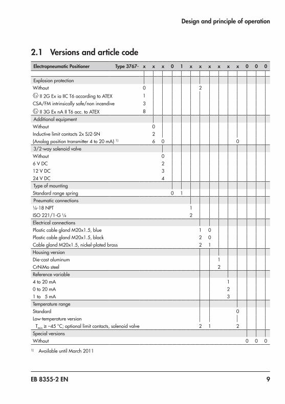
2.1 Versions and article codeElectropneumatic Positioner Type 3767- x x x 0 1 x x x x x x 0 0 0
Explosion protectionWithout 0 2
II2GEx iaIICT6accordingtoATEX 1CSA/FM intrinsically safe/non incendive 3
II3GExnAIIT6acc.toATEX 8Additional equipmentWithout 0Inductive limit contacts 2x SJ2-SN 2(Analogpositiontransmitter4to20 mA)1) 6 0 03/2-way solenoid valveWithout 06 V DC 212 VDC 324 V DC 4Type of mountingStandard range spring 0 1Pneumatic connections¼-18 NPT 1ISO 221/1-G ¼ 2Electrical connectionsPlasticcableglandM20x1.5,blue 1 0PlasticcableglandM20x1.5,black 2 0CableglandM20x1.5,nickel-platedbrass 2 1Housing versionDie-cast aluminum 1CrNiMo steel 2Reference variable4 to 20 mA 10 to 20 mA 21to 5 mA 3Temperature rangeStandard 0Low-temperature version Tmin ≥–45 °C;optionallimitcontacts,solenoidvalve 2 1 2Special versionsWithout 0 0 0
1) Available until March 2011
10 EB 8355-2 EN
Design and principle of operation
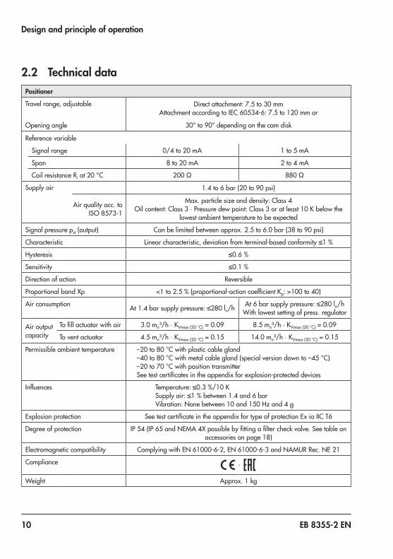
2.2 Technical dataPositioner
Travel range, adjustable Directattachment:7.5to30 mmAttachmentaccordingtoIEC 60534-6:7.5to120 mmor
Opening angle 30°to90°dependingonthecamdisk
Reference variable
Signal range 0/4to20 mA 1to5mA
Span 8 to 20 mA 2 to 4 mA
Coil resistance Riat20 °C 200 Ω 880 Ω
Supply air 1.4to6 bar(20to90 psi)
Air quality acc. to ISO 8573-1
Max. particle size and density: Class 4Oilcontent:Class3·Pressuredewpoint:Class3oratleast10 Kbelowthe
lowest ambient temperature to be expected
Signal pressure pst (output) Canbelimitedbetweenapprox.2.5to6.0 bar(38to90 psi)
Characteristic Linear characteristic, deviation from terminal-based conformity ≤1 %
Hysteresis ≤0.6 %
Sensitivity ≤0.1 %
Direction of action Reversible
ProportionalbandXp <1to2.5 %(proportional-actioncoefficientKp: >100 to 40)
Air consumption At 1.4 bar supply pressure: ≤280 ln/h At6barsupplypressure:≤280 ln/hWith lowest setting of press. regulator
Air output capacity
Tofillactuatorwithair 3.0 mn³/h·KVmax(20 °C) = 0.09 8.5 mn³/h·KVmax(20 °C) = 0.09
To vent actuator 4.5 mn³/h·KVmax(20 °C)=0.15 14.0 mn³/h·KVmax(20 °C)=0.15
Permissible ambient temperature –20to80 °Cwithplasticcablegland–40to80 °Cwithmetalcablegland(specialversiondownto–45 °C)–20to70 °CwithpositiontransmitterSeetestcertificatesintheappendixforexplosion-protecteddevices
Influences Temperature: ≤0.3 %/10 KSupplyair:≤1 %between1.4and6 barVibration:Nonebetween10and150 Hzand4 g
Explosion protection SeetestcertificateintheappendixfortypeofprotectionEx iaIICT6
Degree of protection IP 54(IP 65andNEMA4Xpossiblebyfittingafiltercheckvalve.Seetableonaccessoriesonpage 18)
Electromagnetic compatibility ComplyingwithEN 61000-6-2,EN 61000-6-3andNAMURRec.NE 21
Compliance ·
Weight Approx.1 kg
EB 8355-2 EN 11
Design and principle of operation
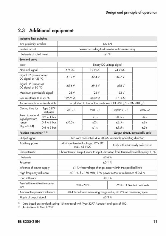
2.3 Additional equipmentInductive limit switches
Two proximity switches SJ2-SN
Control circuit Values according to downstream transistor relay
Hysteresis at rated travel ≤1 %
Solenoid valve
Input Binary DC voltage signal
Nominal signal 6 V DC 12 VDC 24 V DC
Signal '0' (no response) DCsignalat–25 °C ≤1.2 V ≤2.4 V ≤4.7 V
Signal '1' (response) DCsignalat80 °C ≥5.4 V ≥9.6 V ≥18 V
Maximum permissible signal 28 V 25 V 32 V
Coil resistance Riat20 °C 2909 Ω 5832 Ω 11714 Ω
Air consumption in steady state In addition to that of the positioner: OFF ≤60 ln/h · ON ≤10 ln/h
Closing time for
Rated travel and signal pressure range(KVS = 0.14)
Type 3277Actuator 120 cm² 240 cm² 350/355 cm² 700 cm²
0.2to1 bar
≤0.5s
≤1 s ≤1.5 s ≤4 s
0.4to2 bar ≤2 s ≤2.5 s ≤8 s
0.6to3 bar ≤1 s ≤1.5 s ≤5 s
Position transmitter 1), 2) – Output circuit, intrinsically safe
Output signal Two-wireconnection4to20 mA,reversibleoperatingdirection
Auxiliary power Minimumterminalvoltage:12 V DCmax.45 V DC Only with intrinsically safe circuit
Characteristic Characteristic: Output linear to input, deviation from terminal-based linearity ≤1 %
Hysteresis ≤0.6 %
Response ≤0.1 %
Influenceofpowersupply ≤1 %whenvoltagechangesoccurwithinthespecifiedlimits
High-frequencyinfluence ≤0.1 %,f=150 MHz,1 Wpoweroutputatadistanceof0.5 m
Loadinfluence ≤0.1 %
Permissible ambient tempera-ture –20to70 °C –20 to à See test certificate
Ambienttemperatureinfluence ≤0.4 %onlowermeasuringrangevalue,≤0.2 %onmeasuringspan
Ripple of output signal ≤0.3 %
1) Databasedonstandardspring(15 mmtravelwithType 3277Actuator)andgainof100.2) Available until March 2011
12 EB 8355-2 EN
Design and principle of operation
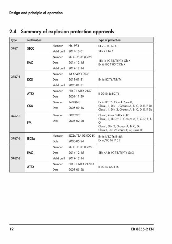
2.4 Summary of explosion protection approvalsType Certification Type of protection
3767 STCCNumber No.974 0ExiaIICT6X
2ExsIIT6XValid until 2017-10-01
3767-1
EACNumber RUCDE.08.00697
1ExiaIICT6/T5/T4GbXExtbIIICT80°CDbXDate 2014-12-15
Valid until 2019-12-14
KCSNumber 13-KB4BO-0037
ExiaIICT6/T5/T4Date 2013-01-31
Valid until 2020-01-31
ATEXNumber PTB01ATEX2167
II2GExiaIICT6Date 2001-11-29
3767-3
CSANumber 1607848 Ex iaIICT6:ClassI,Zone0;
ClassI,II,Div.1,GroupsA,B,C,D,E,F,D;ClassI,II,Div.2,GroupsA,B,C,D,E,F,D;Date 2005-09-16
FM
Number 3020228 ClassI,Zone0AEx iaIICClass I, II, III, Div. 1, Groups A, B, C, D, E, F, GClassI,Div.2,GroupsA,B,C,D;ClassII,Div.2GroupsF,G;ClassIII;
Date 2005-02-28
3767-6 IECExNumber IECExTSA05.0004X ExiaI/IICT6IP65,
ExnI/IICT6IP65Date 2005-05-24
3767-8
EACNumber RUCDE.08.00697
2ExnAicIICT6/T5/T4GcXDate 2014-12-15
Valid until 2019-12-14
ATEXNumber PTB01ATEX2170X
II3GExnAIIT6Date 2003-05-28
EB 8355-2 EN 13
Mounting on control valves
3 Mounting on control valvesThe positioner can be mounted either directly toSAMSONType 3277Actuatorortocon-trol valves with cast yokes or rod-type yokes accordingtoIEC 60534-6(NAMUR).Combined with an intermediate piece, the positioner can also be mounted on rotary actuators. The standard positioner is deliv-ered without accessories. Any additionally required accessories are listed together with their order numbers in the following tables.Do not remove the protective cover on the back of the positioner until you actually start to attach the positioner.
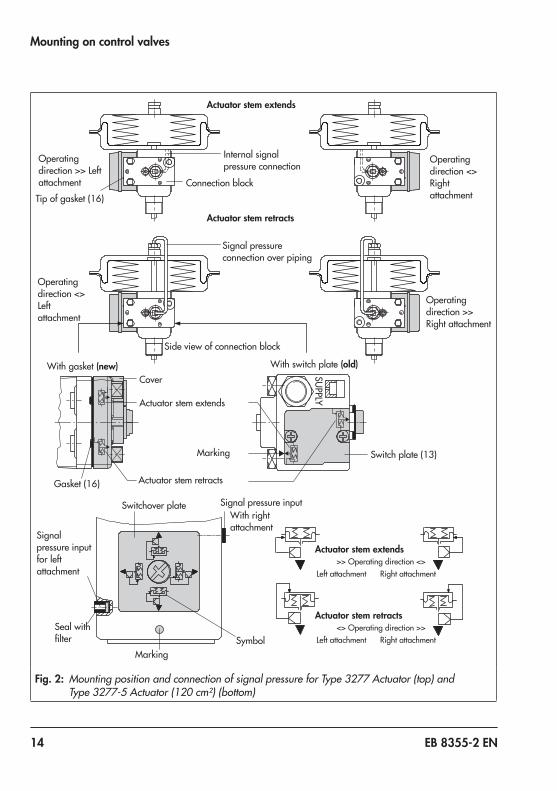
Mounting position and operating directionThe operating direction of the positioner also determines its mounting position on the actu-atorasillustratedinFig. 2,Fig. 3andFig. 5.Theturnboard(7inFig. 1)atthepositionermust be mounted correspondingly.For an increasing input signal (reference variable), the signal pressure pst can either be increasing (direct action >>) or decreas-ing (reverse action <>). Similarly, as the ref-erence variable decreases, the signal pres-sure can either decrease (direct action >>) or increase (reverse action <>).Ontheturnboard(7),theoperatingdirectionis indicated by symbols (direct >>, reverse <>). Depending on the position of the turn-board, the adjusted operating direction and the associated symbol become visible.If the required operating direction does not correspond to the visible symbol or if you want to change the operating direction, re-
move the fastening screw at the turnboard, turntheboardby180°andrefastentheturnboard. Make sure the three rubber gas-kets inserted in the housing remain in posi-tion.
When any subsequent changes are made, e.g. reversing the operating direction of the positioner control loop or changing the actu-ator fail-safe action from “actuator stem ex-tends” to “actuator stem retracts” or vice ver-sa, the positioner's mounting position must be changed accordingly.
3.1 Direct attachment to Type 3277 Actuator
The required accessories are listed in Table 1 to Table 4 on page 17.
The attachment of the positioner either on the left or right side of the actuator (always look-ing onto the signal pressure connection or switchover plate) is determined by the re-quired operating direction of the positioner, i.e. >> or <>.
NOTICE!
Note
14 EB 8355-2 EN
Mounting on control valves
SUPPLY
Actuator stem extends
Actuator stem retracts
Internal signal pressure connection
Side view of connection block
Signal pressure connection over piping
Connection block Tipofgasket(16)
Operating direction >> Left attachment
Operating direction <> Left attachment
With gasket (new) With switch plate (old)
Switch plate (13)
Gasket(16)
Cover
Switchover plate Signal pressure input
Signal pressure input for left attachment
Seal with filter
With right attachment
Marking
MarkingSymbol
Actuator stem extends
Actuator stem retracts
Operating direction <> Right attachment
Actuator stem extends>> Operating direction <>
Left attachment Right attachment
Actuator stem retracts<> Operating direction >>
Left attachment Right attachment
Operating direction >> Right attachment
Fig. 2: Mounting position and connection of signal pressure for Type 3277 Actuator (top) and Type 3277-5 Actuator (120 cm²) (bottom)
EB 8355-2 EN 15
Mounting on control valves
1. Fasten the clamp (1.2) to the actuator stem, making sure that the fastening screw rests in the groove of the actuator stem.
2. Fasten the associated pick-up lever D1 or D2(with355/700 cm²actuators)tothefeedback lever of the positioner.
3. Securetheintermediateplate(15)withthe gasket facing towards the actuator yoke.
4. Position the positioner such that the pick-up lever slides in line over the pin (1.1) of the clamp (1.2). Fasten the positioner totheintermediateplate(15).
5. Mountcover(16).6. Check whether the correct range spring
hasbeeninstalledaslistedinTable 4!Range spring 1 is installed as standard. If necessary, replace it with range spring 2includedintheaccessoriesandfixitatthe outer hook-in holes.
Actuators with 240, 350, 355 and 700 cm² diaphragm areas7. Makesurethatthetipofthegasket (16)
projecting from the side of the connec-tionblock(Fig. 2,middle)ispositionedto match the actuator symbol for the ac-tuator's fail-safe action "actuator stem extends" or "actuator stem retracts".If this is not the case, unscrew the three fastening screws and lift off the cover. Turnthegasket(16)by180°andre-in-sert it.The old connection block version requires the switch plate (13) to be turned to align
the actuator symbol with the arrow mark-ing.
8. Place the connection block with the asso-ciated gaskets against the positioner and the actuator yoke. Fasten it using the screw.For actuators with fail-safe action "actua-tor stem retracts", additionally mount the external signal pressure pipe.
Actuator (120 cm²)The signal pressure is transmitted to the dia-phragm chamber over the switchover plate (Fig. 2andFig. 3,bottom).7. Removescrewplugonthebackofthe
positioner(Fig. 4)andsealthesidesig-nal pressure output with the stopper in-cluded in the accessories.
8. Mount the positioner so that the hole in theintermediateplate(15)coverstheseal in the hole of the actuator yoke.
9. Align the switchover plate with the corre-sponding actuator symbol. Fasten it to the actuator yoke.
If a solenoid valve or a similar device is ad-ditionally mounted onto a 120 cm² actuator, do not remove the M3 screw plug at the back of positioner. In this case, the signal pressure must be transmitted from the signal pressure output to the actuator over an addi-tional connecting plate (Table 2). The swi-tchover plate is not used in this case.
NOTICE!
16 EB 8355-2 EN
Mounting on control valves
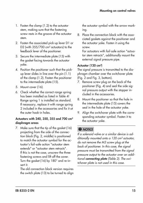
Air purging of the spring chamberIf the spring chamber of the actuator is to be purged with the exhaust air from the posi-tioner,usepiping(Table 3)toconnectthespring chamber (with "actuator stem ex-tends" version) to the connection block. To do so, remove the stopper from the connec-tion block. For an actuator with fail-safe ac-tion "actuator stem retracts" and in Type 3277-5Actuatorswithaneffectivedia-
phragmareaof120 cm²,theexhaustairfrom the positioner is connected to the spring chamber over an internal hole.
When the valve is installed, the side cover of the actuator must be mounted such that the vent plug points downward.
NOTICE!
1.2
D2
D1
15Vent plug
Vent plug must point downward when the valve is installed
View onto the signal pressure connectionLeft attachment Right attachment
Cover
Switchover plate
Intermediateplate(15)
Clamp (1.2)
Signal pressure borehole
240 cm²350 cm²355 cm²700 cm²
120 cm²
Type 3277
Type 3277-5
Fig. 3: Mounting the clamp
EB 8355-2 EN 17
Mounting on control valves
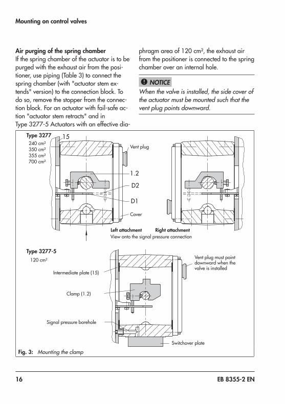
Table 1: Lever (see Fig. 3) Mounting kit
Actuator size Lever with associated clamp and intermediate plate Order no.
120 cm² D1 lever with stopper for output (38)Standard version 1400-7116
Version compatible with paint 1402-0944
240/350 cm² D1lever(33 mmlongwith17 mmclamp)Standard version 1400-6370
Version compatible with paint 1402-0942
355/700 cm² D2lever(44 mmlongwith13 mmclamp)Standard version 1400-6371
Version compatible with paint 1402-0943
Table 2: Switchover plates and connecting plates Order no.
Switchoverplate(for120 cm²actuator) Type3277-5xxxxxx.00 Actuator (old) 1400-6819
New switchover plate Type3277-5xxxxxx.01 Actuator (new) or higher 1400-6822
Connecting plate for additional attachmentof, e.g. a solenoid valve
Type3277-5xxxxxx.00Actuator(old),G 1/8
Type3277-5xxxxxx.00 Actuator (old), 1/8 NPT1400-68201400-6821
New connecting plateType3277-5xxxxxx.01 Actuator (new) or higherG 1/8 and 1/8 NPT
1400-6823
Note: Only new switchover and connecting plates can be used with new actuators (Index 01). Old and new plates are not interchangeable.
Requiredconnectionblockfor240,350,355and700 cm²actuator(including gaskets and fastening screw)
G ¼ 1400-8819
¼ NPT 1402-0901
Table 3: Pipe connection Material Actuatorsize[cm²] Order no.
Requiredpipeconnectionincludingscrewfitting
For actuator with "actuator stem retracts" or with air purging of the top diaphragm chamber
Steel 240 1400-6444
Stainless steel 240 1400-6445
Steel 350 1400-6446
Stainless steel 350 1400-6447
Steel 355/700 1400-6448
Stainless steel 355/700 1400-6449
Table 4: Range spring Travel[mm] Actuatorsize[cm²] Order no.
2(4.5coils) 7.5 120, 240 1400-6443
1(9.5coils,installedasstandard) 10to15 120,240and350 1400-6442
2 15 355/700 1400-6443
1 30 355/700 1400-6442
18 EB 8355-2 EN
Mounting on control valves
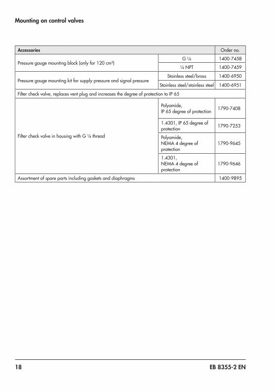
Accessories Order no.
Pressuregaugemountingblock(onlyfor120 cm²)G ¼ 1400-7458
¼ NPT 1400-7459
Pressure gauge mounting kit for supply pressure and signal pressureStainless steel/brass 1400-6950
Stainless steel/stainless steel 1400-6951
Filtercheckvalve,replacesventplugandincreasesthedegreeofprotectiontoIP 65
FiltercheckvalveinhousingwithG ¼thread
Polyamide, IP 65degreeofprotection 1790-7408
1.4301,IP 65degreeofprotection 1790-7253
Polyamide, NEMA 4 degree of protection
1790-9645
1.4301, NEMA 4 degree of protection
1790-9646
Assortment of spare parts including gaskets and diaphragms 1400-9895
EB 8355-2 EN 19
Mounting on control valves
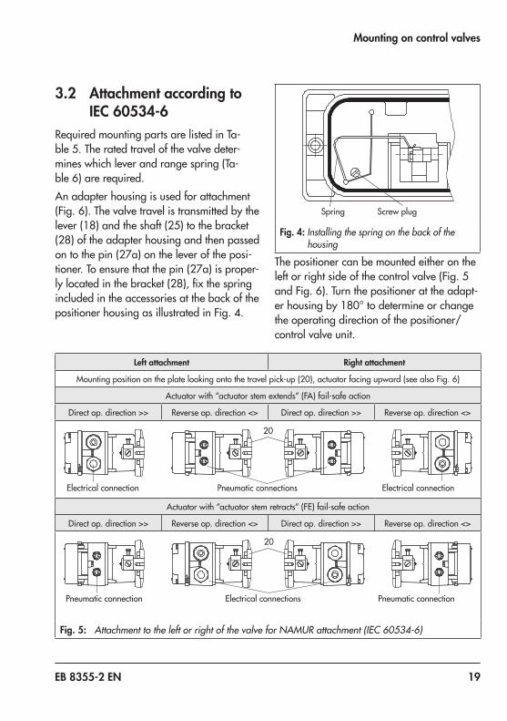
Left attachment Right attachment
Mountingpositionontheplatelookingontothetravelpick-up(20),actuatorfacingupward(seealsoFig. 6)
Actuatorwith“actuatorstemextends”(FA)fail-safeaction
Direct op. direction >> Reverse op. direction <> Direct op. direction >> Reverse op. direction <>
20
Pneumatic connections Electrical connectionElectrical connection
Actuatorwith“actuatorstemretracts”(FE)fail-safeaction
Direct op. direction >> Reverse op. direction <> Direct op. direction >> Reverse op. direction <>
Pneumatic connectionPneumatic connection Electrical connections
20
Fig. 5: Attachment to the left or right of the valve for NAMUR attachment (IEC 60534-6)
3.2 Attachment according to IEC 60534-6
Required mounting parts are listed in Ta-ble 5.Theratedtravelofthevalvedeter-mines which lever and range spring (Ta-ble 6)arerequired.An adapter housing is used for attachment (Fig. 6).Thevalvetravelistransmittedbythelever(18)andtheshaft(25)tothebracket(28) of the adapter housing and then passed ontothepin(27a)ontheleveroftheposi-tioner.Toensurethatthepin(27a)isproper-lylocatedinthebracket(28),fixthespringincluded in the accessories at the back of the positionerhousingasillustratedinFig. 4.
Spring Screw plug
Fig. 4: Installing the spring on the back of the housing
The positioner can be mounted either on the leftorrightsideofthecontrolvalve(Fig. 5andFig. 6).Turnthepositionerattheadapt-erhousingby180°todetermineorchangethe operating direction of the positioner/control valve unit.
20 EB 8355-2 EN
Mounting on control valves
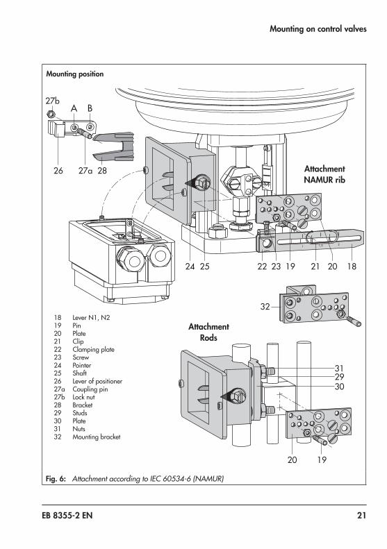
3.2.1 Mounting sequence Î Mounting parts and range spring: see Table 4/Table 5;mountingaccordingtoFig. 6.
Valve with cast yoke1. Screw the plate (20) to the stem connec-
tor of the actuator and plug stems using the countersunk screws.Use the additional bracket (32) for 2100 and2800 cm²actuatorswith120 mmtravel.
2. Remove the rubber stopper from the adapter housing and fasten the adapter housing either on the left or right of the NAMUR rib using the hexagon head screwasshowninFig. 5.
Valve with rod-type yoke1. Screw the plate (20) to the follower
clamp of the plug stem.2. Screw the studs (29) into the adapter
housing.3. Place the adapter housing with the plate
(30) onto either the left or right valve rod and screw tight using the nut (31). Make sure that the adapter housing is at the correct height to mount the lever (18) so that it is in a horizontal position when the valve is at mid-travel.
4. Screw the pin (19) into the middle row of holes on the plate (20) and lock it into position over the correct lever marking (1 or2)asindicatedinTable 6.
5. Clamp the clip (21) onto the lever (18). The clip must be clamped onto the lever (18) with the open side facing down-
ward when the positioner is attached with the air connection at the front.
6. Attach the lever (18) including clamping plate(22)totheshaft(25),makingsurethat the clip clasps the pin (19).
3.2.2 Initial adjustment of travel
1. Movethevalveto50 %travel.2. Movetheshaft(25)intheadapterhous-
ing so that the black pointer (24) match-es the cast marking on the adapter hous-ing.
3. Fasten the clamping plate (22) in this po-sition using the screw (23).
4. Screwthepin(27a)intothepositionerlever on the side where the press nut is located. Lock it in position with the hex nut on the other side, observing the mounting position A or B according to Table 6andFig. 6.
5. Place the positioner on the adapter hous-ing, taking into account the mounting di-rection. Fasten it, making sure that the pin(27a)restsagainstthebracket(28).The pin must not slip out of the bracket once installed.
6. Check whether the correct range spring hasbeeninstalledaslistedinTable 6.Range spring 1 is installed as standard. If necessary, replace it with range spring 2includedintheaccessoriesandfixitatthe outer hook-in holes.
7. Perform positioner setting as described in section 5.1.
EB 8355-2 EN 21
Mounting on control valves
21,51
24 25 22
32
31
20 19
19 21 2023 18
2930
2826
A B27b
27a
Mounting position
AttachmentNAMUR rib
AttachmentRods
18 Lever N1, N219 Pin20 Plate21 Clip22 Clamping plate23 Screw24 Pointer25 Shaft26 Lever of positioner27a Coupling pin27b Lock nut28 Bracket29 Studs30 Plate31 Nuts32 Mounting bracket
Fig. 6: Attachment according to IEC 60534-6 (NAMUR)
22 EB 8355-2 EN
Mounting on control valves
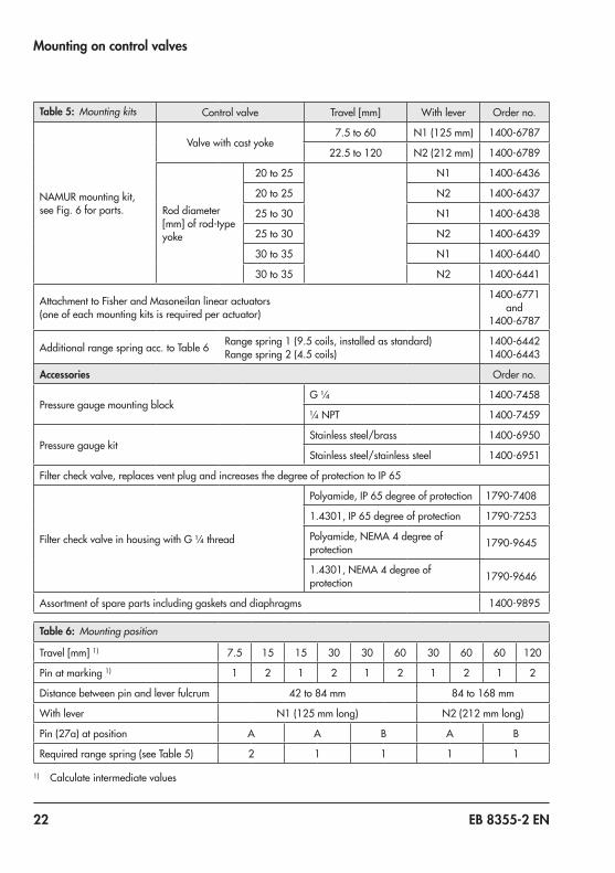
Table 5: Mounting kits Control valve Travel[mm] With lever Order no.
NAMUR mounting kit, seeFig. 6forparts.
Valve with cast yoke7.5to60 N1(125 mm) 1400-6787
22.5to120 N2(212 mm) 1400-6789
Rod diameter [mm]ofrod-typeyoke
20to25 N1 1400-6436
20to25 N2 1400-6437
25to30 N1 1400-6438
25to30 N2 1400-6439
30to35 N1 1400-6440
30to35 N2 1400-6441
Attachment to Fisher and Masoneilan linear actuators (one of each mounting kits is required per actuator)
1400-6771 and
1400-6787
Additionalrangespringacc.toTable 6 Rangespring1(9.5coils,installedasstandard)Rangespring2(4.5coils)
1400-64421400-6443
Accessories Order no.
Pressure gauge mounting blockG ¼ 1400-7458
¼ NPT 1400-7459
Pressure gauge kitStainless steel/brass 1400-6950
Stainless steel/stainless steel 1400-6951
Filtercheckvalve,replacesventplugandincreasesthedegreeofprotectiontoIP 65
FiltercheckvalveinhousingwithG ¼thread
Polyamide,IP 65degreeofprotection 1790-7408
1.4301,IP 65degreeofprotection 1790-7253
Polyamide, NEMA 4 degree of protection 1790-9645
1.4301, NEMA 4 degree of protection 1790-9646
Assortment of spare parts including gaskets and diaphragms 1400-9895
Table 6: Mounting position
Travel[mm]1) 7.5 15 15 30 30 60 30 60 60 120
Pin at marking 1) 1 2 1 2 1 2 1 2 1 2
Distance between pin and lever fulcrum 42to84 mm 84to168 mm
With lever N1(125 mmlong) N2(212 mmlong)
Pin(27a)atposition A A B A B
Requiredrangespring(seeTable 5) 2 1 1 1 1
1) Calculate intermediate values
EB 8355-2 EN 23
Mounting on control valves
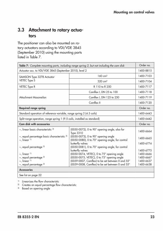
3.3 Attachment to rotary actua-tors
The positioner can also be mounted on ro-taryactuatorsaccordingtoVDI/VDE 3845(September 2010) using the mounting parts listedinTable 7.
Table 7: Complete mounting parts, including range spring 2, but not including the cam disk Order no.
Actuatoracc.toVDI/VDE 3845(September2010),level2 1400-8815
SAMSONType 3278ActuatorVETEC Type S
160 cm² 1400-7103
320 cm² 1400-7104
VETEC Type R R 110toR 250 1400-7117
Attachment Masoneilan
CamflexI,DN 25to100 1400-7118
CamflexI,DN 125to250 1400-7119
CamflexII 1400-7120
Required range spring Order no.
Standardoperationofreferencevariable,rangespring2(4.5coils) 1400-6443
Split-rangeoperation,rangespring1(9.5coils,installedasstandard) 1400-6442
Cam disk with accessories Order no.
~, linear basic characteristic 3)
~, equal percentage basic characteristic 3)
~, linear 1)
~, equal percentage 2)
~, linear 1)
~, equal percentage 2)
~, linear 1)
~, equal percentage 2)
(0050-0072),0to90°openingangle,alsoforType 3310(0050-0073),0to90°openingangle(0050-0080),0to70°openingangle,forcontrolbutterflyvalves(0050-0081),0to70°openingangle,forcontrolbutterflyvalves(0050-0074,VETEC),0to75°openingangle(0050-0075,VETEC),0to75°openingangle(0059-0007,Camflex)tobesetbetween0and55°(0059-0008,Camflex)tobesetbetween0and55°
1400-6664
1400-6665
1400-6774
1400-67751400-66661400-66671400-66371400-6638
Accessories
Seelistonpage 22
1) Linearizestheflowcharacteristic2) Createsanequalpercentageflowcharacteristic3) Based on opening angle
24 EB 8355-2 EN
Mounting on control valves
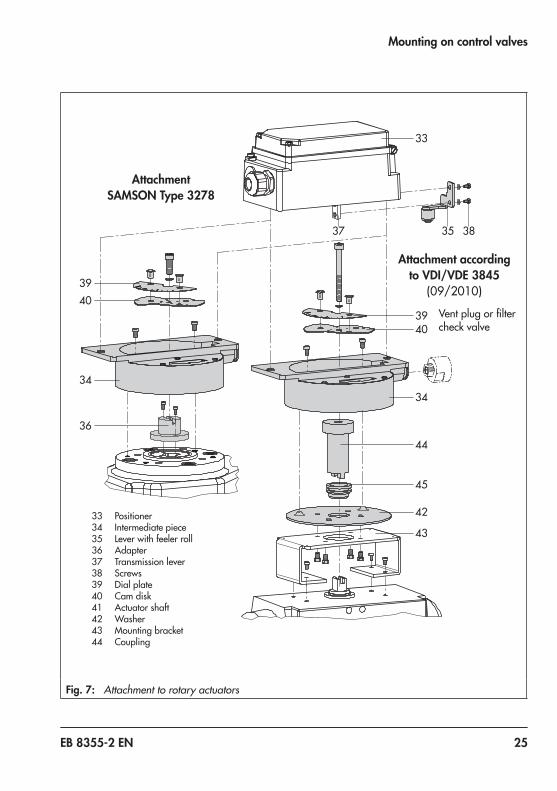
The rotary motion of these actuators is con-verted into a linear motion required by the pneumatic control unit of the positioner using the cam disk of the actuator shaft and a feel-er roll on the positioner lever.
Check whether the correct range spring has been installed as listed in Table 7. Range spring 1 is installed as standard. If neces-sary, replace it with range spring 2 included in the accessories and fix it at the outer hook-in holes.
Double-acting springless rotary actuators re-quire the use of a reversing amplifier on the connection side of the positioner housing (seesection 3.3.4).Whenusingareversingamplifier,thepres-sureregulator(9,Fig. 1)mustbeturnedclockwise as far as it will go (also see sec-tion 4.1.2).When attaching the positioner to the SAM-SONType 3278RotaryActuator(Fig. 7,left), the inside of the actuator and the un-used reverse side of the diaphragm are purged with the positioner's exhaust air. Ad-ditional piping is not required.When attaching the positioner to actuators fromothermanufacturers(Fig. 7,right),thereverse side of the diaphragm can be purged with air over a pipe connection in-stalled between the actuator and intermedi-ate piece.
3.3.1 Mounting the lever with feeler roll
1. Placetheleverwithfeelerroll(35)onthesideofthelever(37)oppositetowherethe press nuts are located and secure it using the supplied screws (38) and washers.
To ensure a close physical contact between the lever with feeler roll and the cam disk, attach the spring contained in the accesso-ries kit (order no. 1400-6660) to the back of the positioner housing (see Fig. 4).
3.3.2 Mounting the interme-diate piece
SAMSON Type 3278 Actuator1. Fastentheadapter(36)tothefreeshaft
end of the rotary actuator.2. Fasten the intermediate piece (34) to the
actuator housing using two screws. Align the intermediate piece so that the air connections of the positioner point to-ward the diaphragm case side.
3. Align the cam disk (40) and scale (39) as described in section 3.3.3 and fasten.
Actuators according to VDI/VDE 3845 (09/2010) (fixinglevel2)1. Place the assembled intermediate piece
(34,44,45and42)ontothemountingbracket included in the scope of actuator delivery and fasten.
2. Align the cam disk (40) and scale (39) as described in section 2.3.3 and fasten.
NOTICE!
NOTICE!
EB 8355-2 EN 25
Mounting on control valves
33
3835
39
39
40
34
36
40
34
44
45
42
43
37
Attachment according to VDI/VDE 3845
(09/2010)
AttachmentSAMSON Type 3278
33 Positioner34 Intermediate piece35 Lever with feeler roll36 Adapter37 Transmission lever38 Screws39 Dial plate40 Cam disk41 Actuator shaft42 Washer43 Mounting bracket44 Coupling
Ventplugorfiltercheck valve
Fig. 7: Attachment to rotary actuators
26 EB 8355-2 EN
Mounting on control valves
3.3.3 Basic setting of the cam disk
The valve model used determines the basic setting of the cam disk.
Cam disks tailored to the special characteris-tic of a valve cause the valve to open in a non-linear or non-equal percentage way.The visible difference between the set point (4 to 20 mA) and the actual position (open-ing angle) does not constitute a system devi-ation of the positioner.
Fig. 8andFig. 9showlinearcamdisks.Fig. 8illustratesacontrolvalveassemblywith a rotary actuator with spring-return mechanism that opens counterclockwise. The arrangement of the springs in the actuator determines the fail-safe position of the valve.Fig. 9showshowtoadjustthecamdiskwhen a double-acting springless rotary actu-ator is used. The direction of rotation (either counterclockwise or clockwise) depends on the actuator and valve model used. The cam disk must be set when the valve is closed.Usetheturnboard(7)toadjusttheoperatingdirection of the positioner, i.e. whether the valve opens or closes when the reference variable increases (direct >> or reverse <>).
Each cam disk carries two cam sections whose starting points are indicated by small holes. Depending on the operating direction of the rotary actuator (air-to-open or air-to-close), the starting point of the cam, either marked N (standard characteristic) or I (re-verse characteristic), must point towards the lever with feeler roll. When the starting point is located on the back of the cam disk, turn over the cam disk.
The starting point (hole) of the selected cam must be aligned so that the fulcrum of the cam disk and 0° position on the scale as well as the arrow on the window are in line with each other.
When aligning the cam disk, clip the dou-ble-sided scale disk on the cam disk, while making sure that the value on the scale matches the valve's direction of rotation.
Make sure the 0° position of the scale al-ways corresponds to CLOSED position.Therefore, for fail-open actuators and for springless actuators, the maximum supply pressure needs to be applied to the actuator before aligning the cam disk.
NOTICE!
NOTICE!
NOTICE!
EB 8355-2 EN 27
Mounting on control valves
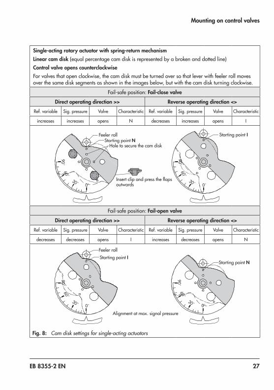
Single-acting rotary actuator with spring-return mechanismLinear cam disk (equal percentage cam disk is represented by a broken and dotted line)Control valve opens counterclockwiseFor valves that open clockwise, the cam disk must be turned over so that lever with feeler roll moves over the same disk segments as shown in the images below, but with the cam disk turning clockwise.
Fail-safe position: Fail-close valve
Direct operating direction >> Reverse operating direction <>Ref. variable Sig. pressure Valve Characteristic Ref. variable Sig. pressure Valve Characteristic
increases increases opens N decreases increases opens I
90˚60˚
30˚ 0˚
90˚60˚
30˚ 0˚
Feeler rollStarting point N
Starting point I
Hole to secure the cam disk
Insertclipandpresstheflapsoutwards
Fail-safe position: Fail-open valve
Direct operating direction >> Reverse operating direction <>Ref. variable Sig. pressure Valve Characteristic Ref. variable Sig. pressure Valve Characteristic
decreases decreases opens I increases decreases opens N
90˚60˚
30˚ 0˚
90˚60˚
30˚ 0˚
Feeler roll
Starting point NStarting point I
Alignment at max. signal pressure
Fig. 8: Cam disk settings for single-acting actuators
28 EB 8355-2 EN
Mounting on control valves
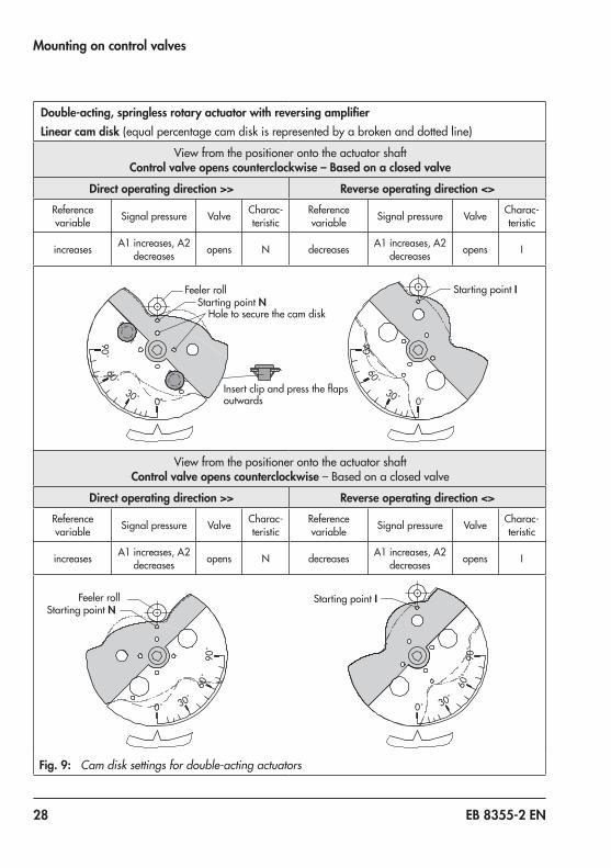
Double-acting, springless rotary actuator with reversing amplifierLinear cam disk (equal percentage cam disk is represented by a broken and dotted line)
View from the positioner onto the actuator shaftControl valve opens counterclockwise – Based on a closed valve
Direct operating direction >> Reverse operating direction <>Reference variable Signal pressure Valve Charac-
teristic
increases A1 increases, A2 decreases opens N
Reference variable Signal pressure Valve Charac-
teristic
decreases A1 increases, A2 decreases opens I
90˚60˚
30˚ 0˚
90˚60˚
30˚ 0˚
Feeler rollStarting point N
Starting point I
Hole to secure the cam disk
Insertclipandpresstheflapsoutwards
View from the positioner onto the actuator shaftControl valve opens counterclockwise – Based on a closed valve
Direct operating direction >> Reverse operating direction <>Reference variable Signal pressure Valve Charac-
teristic
increases A1 increases, A2 decreases opens N
Reference variable Signal pressure Valve Charac-
teristic
decreases A1 increases, A2 decreases opens I
0˚
90˚
60˚
30˚0˚
90˚
60˚
30˚
Feeler rollStarting point N
Starting point I
Fig. 9: Cam disk settings for double-acting actuators
EB 8355-2 EN 29
Mounting on control valves
Securing the aligned cam diskTo prevent the cam disk from turning, drill a holeintotheadapter(36)orcoupling(44)toallowa2 mmdowelpintobeinserted.Select one of the four holes located around the center hole of the cam disk to secure the cam disk in position.
30 EB 8355-2 EN
Mounting on control valves
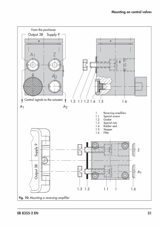
3.3.4 Reversing amplifier for double-acting actuators
For the use with double-acting actuators, the positionermustbefittedwithareversingam-plifier,e.g.theSAMSONType 3710Revers-ingAmplifier(seeMountingandOperatingInstructions u EB 8392).The signal pressure of the positioner is sup-plied at the output A1 of the reversing ampli-fier.Anopposingpressure,whichequalstherequired supply pressure Z when added to the pressure at A1, is applied at output A2. The rule A1 + A2 = Z applies.Ifadifferentreversingamplifier(itemno.1079-1118or1079-1119)isused,followthe mounting instructions described below:
Mounting
When using a reversing amplifier, the pres-sure regulator (9) must be turned as far as it will go in the clockwise direction.Remove the sealing plug (1.5) before mount-ing the reversing amplifier. The rubber seal (1.4) must remain installed.
1. Screw the special nuts (1.3) from the ac-cessoriesofthereversingamplifierintothe threaded connections of the position-er.
2. Insert the gasket (1.2) into the recess of thereversingamplifierandslideboththehollowed special screws (1.1) into the connecting boreholes A1 and Z.
3. Placethereversingamplifierontothepo-sitioner and screw tight using the two special screws (1.1).
4. Use a screwdriver (8 mm wide) to screw theenclosedfilters(1.6)intotheconnec-tion boreholes A1 and Z.
Signal pressure connectionsA1: Connect output A1 to the signal pressure connection on the actuator that causes the valve to open when the pressure rises.A2: Connect output A2 to the signal pressure connection on the actuator that causes the valve to close when the pressure rises.
Pressure gauge attachmentThemountingsequenceshowninFig. 10re-mains unchanged. Screw a pressure gauge bracket onto the connections A1 and Z.Pressure gauge bracket: − G ¼:1400-7106 − ¼NPT:1400-7107
Pressure gauges for supply air Z and output A1aslistedinTable 4andTable 5.
NOTICE!
EB 8355-2 EN 31
Mounting on control valves
1.3 1.2 1.1 1
Out
put 3
8Su
pply
9
A1
1.5 1.6
Z
A2
1.4A1 A2
Output 38 Supply 9
1.3 1.21.1
1.6
Z
A1
From the positioner
Control signals to the actuator
1 Reversingamplifiers1.1 Special screws1.2 Gasket1.3 Special nuts1.4 Rubber seal1.5 Stopper1.6 Filter
Fig. 10: Mounting a reversing amplifier
32 EB 8355-2 EN
Connections
4 Connections
4.1 Pneumatic connectionsThe pneumatic connections are optionally designedasaborewith¼ NPTorG ¼thread.Customaryfittingsformetalorcop-per tubing or plastic hoses can be used.
The supply air must be dry and free from oil and dust. The maintenance instructions for upstream pressure reducing stations must be observed.Blow through all air pipes and hoses thor-oughly before connecting them.
If the positioner is attached directly to the Type 3277Actuator,theconnectionofthepositioner's output pressure to the actuator is fixed.ForattachmentaccordingtoIEC 60534-6(NAMUR),thesignalpressurecan be routed to either the top or bottom di-aphragm chamber of the actuator, depend-ing on the actuator's fail-safe action "actua-tor stem extends" or "actuator stem retracts".
Exhaust airModelswithindex3767-x...x.03 and higher are equipped with a hinged cover without its own exhaust air port. The exhaust air con-nections for these models are included in the accessories.The vent plug is located on the plastic cover of the actuator for direct attachment, where-as for NAMUR attachment, it is located on the adapter housing. The vent plug is located
on the intermediate piece or reversing ampli-fierforattachmenttorotaryactuators.
If you intend to replace older models with in-dex 3767-x...x.02 or lower, the mounting parts may need to be replaced as well.
4.1.1 Pressure gaugesTo precisely tune the positioner, we recom-mend installing pressure gauges for the sup-ply air and signal pressure.The required parts are listed as accessories inTable 4,Table 5andTable 7.
4.1.2 Supply pressureThe required supply air pressure depends on the bench range and the actuator's operat-ing direction (fail-safe action).The bench range is written on the nameplate either as the bench range or signal pressure range. The operating direction is marked FA or FE or by a symbol.Actuator stem extends (FA):Fail-close(for globe and angle valves)Required supply pressure = Upperbenchrangevalue+0.2 bar, atleast1.4 bar.
NOTICE!
NOTICE!
EB 8355-2 EN 33
Connections
Actuator stem retracts (FE):Fail-open(for globe and angle valves)For tight-closing valves, the maximum signal pressure pstmax is roughly estimated as fol-lows:
pstmax = F + d²·π·∆p [bar]4 · A
d = Seatdiameter[cm]∆p = Differential pressure across the
valve[bar]A = Actuatorarea[cm²]F = Upper bench range value of the
actuator[bar]
If there are no specifications, calculate as follows:Required supply pressure =Upperbenchrangevalue+1 bar
Pressure regulatorAfter tilting the cover plate back, the pres-sure regulator (9) can be continuously ad-justed. When the adjuster is turned counter-clockwise as far as it will go, signal pres-suresforspringrangesupto2.5 bararecontrolled. When the adjuster is turned clockwise all the way, signal pressures for springrangesupto6.0 bararecontrolled.If the signal pressure must not exceed a cer-tain value, this limit can be adjusted using a pressure gauge (accessories).
34 EB 8355-2 EN
Connections
4.2 Electrical connections
For electrical installation, observe the rele-vant electrotechnical regulations and the ac-cident prevention regulations that apply in the country of use. In Germany, these are the VDE regulations and the accident pre-vention regulations of the employers’ liability insurance.The following regulations apply to installa-tion in hazardous areas: EN 60079-14: 2008 (VDE 0165, Part 1) Explosive At-mospheres – Electrical Installations Design, Selection and Erection.Adhere to the terminal assignment. Switch-ing the assignment of the electrical terminals may cause the explosion protection to be-come ineffective. Do not loosen enameled screws in or on the housing. The maximum permissible values specified in the EC-type examination certificates apply when inter-connecting intrinsically safe electrical equip-ment (Ui or U0, li or I0, Pi or P0, Ci or C0 and Li or L0).
Selecting cables and wiresObserve clause 12 of EN 60079-14: 2008 (VDE 0165,Part 1)forinstallationofthein-trinsically safe circuits.Clause 12.2.2.7applieswhenrunningmulti-core cables and wires with more than one intrinsically safe circuit.The radial thickness of the insulation of a conductor for common insulating materials
(e.g. polyethylene) must not be smaller than 0.2 mm.The diameter of an individual wire in a fine-strandedconductormustnotbesmallerthan0.1 mm.Protecttheconductorendsagainst splicing, e.g. by using wire-end fer-rules.When two separate cables are used for con-nection, an additional cable gland can be installed.Seal cable entries left unused with plugs.Fit equipment used in ambient temperatures below –20 °C with metal cable entries.
Zone 2/Zone 22In equipment operated according to type of protectionEx nAII(non-sparkingequipment)accordingtoEN 60079-15:2003,circuitsmay be connected, interrupted or switched while energized only during installation, maintenance or repair.Equipment connected to energy-limited cir-cuitswithtypeofprotectionEx nLaccordingtoEN 60079-15:2003maybeswitchedun-der normal operating conditions.The maximum permissible values specified in the statement of conformity and its ad-denda apply when interconnecting the equipment with energy-limited circuits in type of protection Ex nL IIC.
DANGER!
EB 8355-2 EN 35
Connections
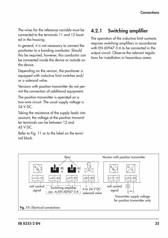
The wires for the reference variable must be connected to the terminals 11 and 12 locat-ed in the housing.In general, it is not necessary to connect the positioner to a bonding conductor. Should this be required, however, this conductor can be connected inside the device or outside on the device.Depending on the version, the positioner is equipped with inductive limit switches and/or a solenoid valve.Versions with position transmitter do not per-mit the connection of additional equipment.The position transmitter is operated on a two-wire circuit. The usual supply voltage is 24 V DC.Taking the resistance of the supply leads into account, the voltage at the position transmit-ter terminals can be between 12 and 45 V DC.RefertoFig. 11ortothelabelonthetermi-nal block.
4.2.1 Switching amplifierThe operation of the inductive limit contacts requiresswitchingamplifiersinaccordancewithEN 60947-5-6tobeconnectedintheoutput circuit. Observe the relevant regula-tions for installation in hazardous areas.
+41 –42 +51 –52 +81 –82 +31 –32
GEi
+ –
+ –
(B)A
(A)B
A
+11 –12 +11 –12
Ei/Ei/ AA
mA control signal
mA control signal6to24 V DC
solenoid valveTransmitter supply voltage
for position transmitter only
Rear Version with position transmitter
Switchingamplifieracc.toEN 60947-5-6
Fig. 11: Electrical connections
36 EB 8355-2 EN
Connections
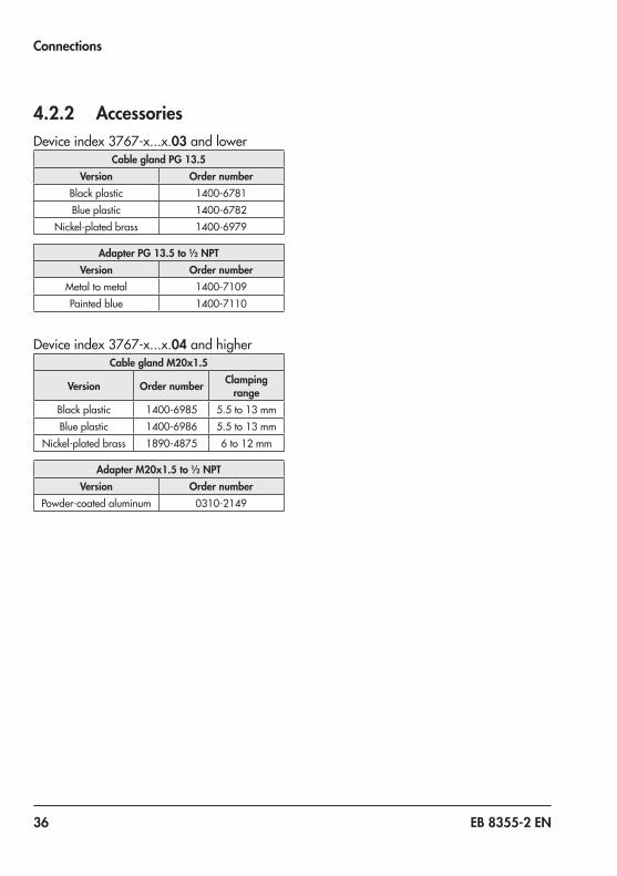
4.2.2 AccessoriesDeviceindex3767-x...x.03 and lower
Cable gland PG 13.5Version Order number
Black plastic 1400-6781Blue plastic 1400-6782
Nickel-plated brass 1400-6979
Adapter PG 13.5 to ½ NPTVersion Order number
Metal to metal 1400-7109Painted blue 1400-7110
Deviceindex3767-x...x.04 and higherCable gland M20x1.5
Version Order number Clamping range
Black plastic 1400-6985 5.5to13 mmBlue plastic 1400-6986 5.5to13 mm
Nickel-plated brass 1890-4875 6to12 mm
Adapter M20x1.5 to ½ NPTVersion Order number
Powder-coated aluminum 0310-2149
EB 8355-2 EN 37
Operation
5 Operation
5.1 Tuning the positioner mounted onto the control valve
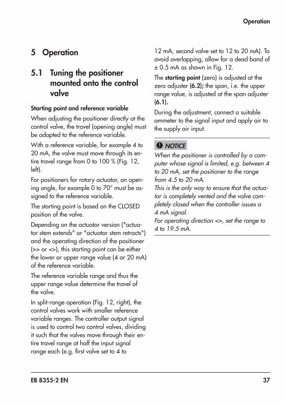
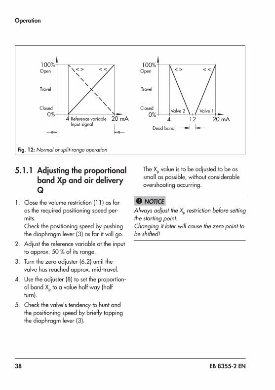
Starting point and reference variableWhen adjusting the positioner directly at the control valve, the travel (opening angle) must be adapted to the reference variable.With a reference variable, for example 4 to 20 mA,thevalvemustmovethroughitsen-tiretravelrangefrom0to100 %(Fig. 12,left).For positioners for rotary actuator, an open-ingangle,forexample0to70°mustbeas-signed to the reference variable.The starting point is based on the CLOSED position of the valve.Depending on the actuator version ("actua-tor stem extends" or "actuator stem retracts") and the operating direction of the positioner (>> or <>), this starting point can be either thelowerorupperrangevalue(4or20 mA)of the reference variable.The reference variable range and thus the upper range value determine the travel of the valve.Insplit-rangeoperation(Fig. 12,right),thecontrol valves work with smaller reference variable ranges. The controller output signal is used to control two control valves, dividing it such that the valves move through their en-tire travel range at half the input signal rangeeach(e.g.firstvalvesetto4to
12 mA,secondvalvesetto12to20 mA).Toavoid overlapping, allow for a dead band of ±0.5 mAasshowninFig. 12.The starting point (zero) is adjusted at the zero adjuster (6.2); the span, i.e. the upper range value, is adjusted at the span adjuster (6.1).During the adjustment, connect a suitable ammeter to the signal input and apply air to the supply air input.
When the positioner is controlled by a com-puter whose signal is limited, e.g. between 4 to 20 mA, set the positioner to the range from 4.5 to 20 mA.This is the only way to ensure that the actua-tor is completely vented and the valve com-pletely closed when the controller issues a 4 mA signal.For operating direction <>, set the range to 4 to 19.5 mA.
NOTICE!
38 EB 8355-2 EN
Operation
100%
0%4 20 mA124 20 mA
100%
0%
< > < < < > < <
Reference variable Input signal
Dead band
OpenOpen
TravelTravel
ClosedClosed Valve 2 Valve 1
Fig. 12: Normal or split-range operation
5.1.1 Adjusting the proportional band Xp and air delivery Q
1. Close the volume restriction (11) as far as the required positioning speed per-mits.Check the positioning speed by pushing the diaphragm lever (3) as far it will go.
2. Adjust the reference variable at the input toapprox.50 %ofitsrange.
3. Turnthezeroadjuster(6.2)untilthevalve has reached approx. mid-travel.
4. Use the adjuster (8) to set the proportion-albandXp to a value half way (half turn).
5. Check the valve's tendency to hunt and thepositioningspeedbybrieflytappingthe diaphragm lever (3).
TheXp value is to be adjusted to be as small as possible, without considerable overshooting occurring.
Always adjust the Xp restriction before setting the starting point.Changing it later will cause the zero point to be shifted!
NOTICE!
EB 8355-2 EN 39
Operation
5.1.2 Settings for actuator with “actuator stem ex-tends” fail-safe action
Starting point (e.g. 4 mA)1. Set the input signal at the ammeter to
4.5 mA2. Turnthezeroadjuster(6.2)untilthe
valve just starts to move from its initial position.
3. Reducetheinputsignalto0 mAandslowly increase it again. Check whether the valve starts to move at exactly 4.5 mA.Correctanydeviationattheze-roadjuster(6.2).
Upper range value (span) e.g. 20 mA1. Once the starting point has been set, in-
creasetheinputsignalto20 mAattheammeter.
Atexactly20 mA,theplugstemmuststandstill,havingmovedthrough100 %travel(watch the travel indicator at the valve).If the upper range value is incorrect, turn the span adjuster (travel). Four turns correspond toatravelchangeof10 %instandardoper-ation. In split-range operation, this value is reduced by half.Turn the adjuster clockwise to reduce the travel and counterclockwise to increase it.2. After the correction has been completed,
reduce the input signal and slowly in-crease it again.Check the starting point and the upper range value. Repeat the correction pro-cedure until both values are correct.
When setting the zero adjuster (6.2), check whether the actuator is relieved of pressure.When the input signal is 4 mA and the oper-ating direction >> or the input signal is 20 mA and the operating direction <>, the pressure gauge must indicate 0 bar.Correct zero accordingly!
5.1.3 Settings for actuator with “actuator stem retracts” fail-safe action
When using an actuator with fail-safe action "actuator stem retracts", the diaphragm chamber must be pressurized with a signal pressure that is high enough to tightly close the valve against the upstream pressure in the plant. This applies to an upper range val-ue of the reference variable (20 mA) with operating direction >> as well as a lower range value of the reference variable (4 mA) with operating direction <>.
The required signal pressure is either indi-cated on the positioner label or the required supply pressure can be roughly calculated as described in section 4.1.2.
Starting point (e.g. 20 mA)1. Set the input signal at the ammeter to
20 mA2. Turnthezeroadjuster(6.2)untilthe
valve just starts to move from its initial position.
NOTICE!
NOTICE!
40 EB 8355-2 EN
Operation
3. Increase the input signal and slowly re-duceitagainto20 mA.Checkwhetherthe valve starts to move at exactly 20 mA.
4. Correct any deviation at the zero adjust-er(6.2).Turningtheadjustercounter-clockwise causes the valve to move from itsendpositionearlier;turningclockwisecauses the valve to move from its end po-sition later.
Upper range value (span) e.g. 4 mA1. Once the starting point has been set, in-
creasetheinputsignalto4 mAattheammeter.Atexactly4 mA,theplugstemmust stand still, having moved through 100 %travel(watchthetravelindicatorat the valve).
2. If the upper range value is incorrect, turn the span adjuster (travel). Four turns cor-respondtoatravelchangeof10 %instandard operation. In split-range opera-tion, this value is reduced by half.Turn the adjuster clockwise to reduce the travel and counterclockwise to increase it.
3. After the correction has been completed, settheinputsignalto20 mAagain.
4. Turnthezeroadjuster(6.2)againuntilthe pressure gauge indicates the re-quired signal pressure (see section 4.1.2).
After mounting and tuning the positioner, make sure that the vent plug of the housing cover faces downward when the valve is in-stalled.
5.2 Changing the operating direction
If the operating direction of directly attached positioners(Fig. 2)istobechangedafterthey have been installed, turn the turnboard (7)andchangethepositionoftheconnec-tion block, positioner and clamp (1.2).ForattachmentaccordingtoIEC 60534-6(NAMUR),turntheturnboard(7)andthepositionerontheadapterhousing(Fig. 5).In positioners for rotary actuators, reassign thecamdiskasshowninFig. 8andFig. 9.Fordetailsonchangingtheturnboard(7)re-fer to section 3.
NOTICE!
EB 8355-2 EN 41
Operation
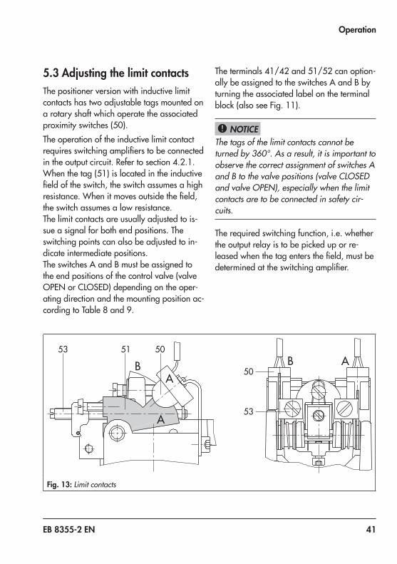
5.3 Adjusting the limit contactsThe positioner version with inductive limit contacts has two adjustable tags mounted on a rotary shaft which operate the associated proximityswitches(50).The operation of the inductive limit contact requiresswitchingamplifierstobeconnectedintheoutputcircuit.Refertosection 4.2.1.Whenthetag(51)islocatedintheinductivefieldoftheswitch,theswitchassumesahighresistance.Whenitmovesoutsidethefield,the switch assumes a low resistance.The limit contacts are usually adjusted to is-sue a signal for both end positions. The switching points can also be adjusted to in-dicate intermediate positions.The switches A and B must be assigned to the end positions of the control valve (valve OPEN or CLOSED) depending on the oper-ating direction and the mounting position ac-cordingtoTable 8and9.
Theterminals41/42and51/52canoption-ally be assigned to the switches A and B by turning the associated label on the terminal block(alsoseeFig. 11).
The tags of the limit contacts cannot be turned by 360°. As a result, it is important to observe the correct assignment of switches A and B to the valve positions (valve CLOSED and valve OPEN), especially when the limit contacts are to be connected in safety cir-cuits.
The required switching function, i.e. whether the output relay is to be picked up or re-leasedwhenthetagentersthefield,mustbedeterminedattheswitchingamplifier.
NOTICE!
Fig. 13: Limit contacts
42 EB 8355-2 EN
Operation
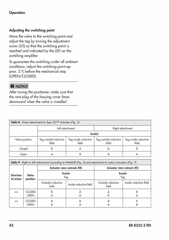
Adjusting the switching pointMove the valve to the switching point and adjust the tag by turning the adjustment screw(53)sothattheswitchingpointisreached and indicated by the LED on the switchingamplifier.To guarantee the switching under all ambient conditions, adjust the switching point ap-prox.2 %beforethemechanicalstop(OPEN/CLOSED).
After tuning the positioner, make sure that the vent plug of the housing cover faces downward when the valve is installed.
NOTICE!
Table 8: Direct attachment to Type 3277 Actuator (Fig. 2)
Left attachment Right attachment
Switch
Valve position Tag outside inductive field
Tag inside inductive field
Tag outside inductive field
Tag inside inductive field
Closed B A A B
Open A B B A
Table 9: Right or left attachment according to NAMUR (Fig. 5) and attachment to rotary actuators (Fig. 7)
Direction of action
Valve position
Actuator stem extends (FA) Actuator stem retracts (FE)
SwitchTag
SwitchTag
Outside inductive field Insideinductivefield Outside inductive
fieldInsideinductivefield
>> CLOSED OPEN
B A
A B
A B
B A
<> CLOSED OPEN
A B
B A
B A
A B
EB 8355-2 EN 43
Operation
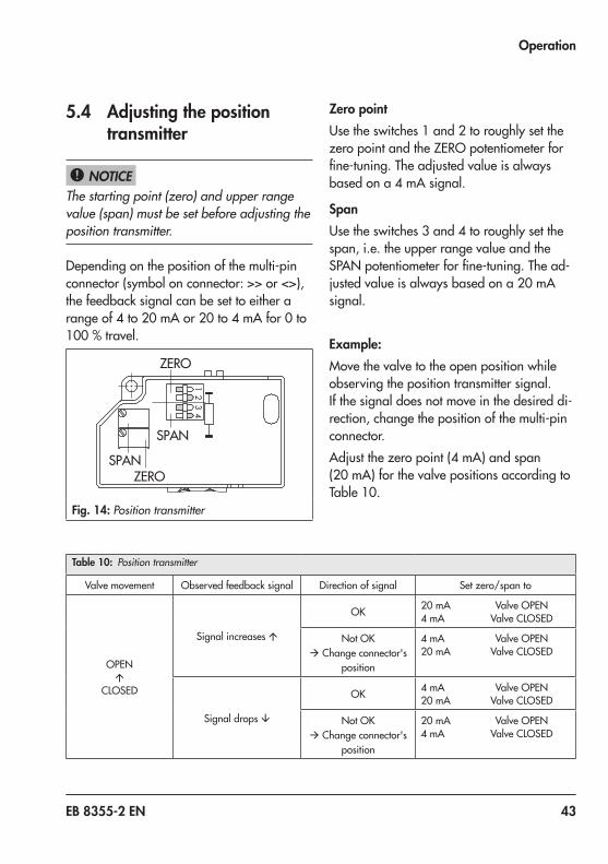
5.4 Adjusting the position transmitter
The starting point (zero) and upper range value (span) must be set before adjusting the position transmitter.
Depending on the position of the multi-pin connector (symbol on connector: >> or <>), the feedback signal can be set to either a rangeof4to20 mAor20to4 mAfor0to100 %travel.
Fig. 14: Position transmitter
Zero pointUse the switches 1 and 2 to roughly set the zero point and the ZERO potentiometer for fine-tuning.Theadjustedvalueisalwaysbasedona4 mAsignal.
SpanUse the switches 3 and 4 to roughly set the span, i.e. the upper range value and the SPANpotentiometerforfine-tuning.Thead-justedvalueisalwaysbasedona20 mAsignal.
Example:Move the valve to the open position while observing the position transmitter signal.If the signal does not move in the desired di-rection, change the position of the multi-pin connector.Adjustthezeropoint(4 mA)andspan(20 mA)forthevalvepositionsaccordingtoTable 10.
NOTICE!
Table 10: Position transmitter
Valve movement Observed feedback signal Direction of signal Set zero/span to
OPEN á
CLOSED
Signal increases á
OK 20 mA ValveOPEN4 mA ValveCLOSED
NotOK à Change connector's
position
4 mA ValveOPEN20 mA ValveCLOSED
Signal drops â
OK 4 mA ValveOPEN20 mA ValveCLOSED
NotOK à Change connector's
position
20 mA ValveOPEN4 mA ValveCLOSED
44 EB 8355-2 EN
Operation
Zero point adjustment1. Use the input signal of the positioner to
move the valve to closed position (valve CLOSED,travel0 %).
2. The ammeter must now indicate approx. 4 mA.
3. Correct smaller deviations at the ZERO potentiometer until the meter shows ex-actly4 mA.For larger deviations that cannot be cor-rected using the potentiometer (adjust-ment range of approx. 20 turns), set the switches 1 and 2 to indicate an mA val-ue which is within the adjustment range of the ZERO potentiometer.
4. Setthezeropointtoexactly4 mAusingthe ZERO potentiometer.
Adjusting the span1. Use the input signal of the positioner to
move the valve to closed position (valve CLOSED,travel100 %).
2. The ammeter must now indicate approx. 20 mA.
3. Correct smaller deviations at the SPAN potentiometer until the meter shows ex-actly20 mA.Ifdeviationsaretoohigh,set the switches 3 and 4 to indicate an mA signal which is within the adjustment range of the SPAN potentiometer.
4. Turn the SPAN potentiometer until the ammetershowsexactly20 mA.Since the zero point and span have a mutualinfluenceoneachother,repeatthe correction procedure at both potenti-ometers until both values are correct.
EB 8355-2 EN 45
Operation
The following applies to positioners with adapter housing for NAMUR attachment:When the positioner and the position trans-mitter signal have different operating direc-tions (<< and <>), it may be impossible to adjust the zero point of the transmitter signal due to the additional deflection caused by the bracket (28) of the adapter housing.In this case, readjust the black pointer (sec-tion 3.2.2 on page 16) so that the sensor of the position transmitter reaches the control range.Unscrew the clamp. For “actuator stem ex-tends” (FA), shift the pointer upward towards the actuator; for "actuator stem retracts" (FE), shift the pointer downward towards the valve. For valves with rod-type yoke, slightly shift the positioner on the rod in the down-ward (FE) or upward (FA) direction.
Every time you make a change as described above, the zero point and span of the posi-tioner must be readjusted before adjusting the position transmitter.After tuning the positioner, make sure that the vent plug of the housing cover faces downward when the valve is installed.
Note NOTICE!
46 EB 8355-2 EN
Upgrading and retrofitting the positioner
6 Upgrading and retrofitting the positioner
Read instructions in section 7 for explo-sion-protected versions!
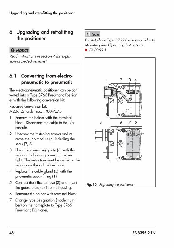
6.1 Converting from electro-pneumatic to pneumatic
The electropneumatic positioner can be con-vertedintoaType 3766PneumaticPosition-er with the following conversion kit:Required conversion kit:M20x1.5,orderno.:1400-75751. Remove the holder with the terminal
block. Disconnect the cable to the i/p module.
2. Unscrew the fastening screws and re-movethei/pmodule(6)includingtheseals(7,8).
3. Place the connecting plate (3) with the seal on the housing bores and screw tight. The restriction must be seated in the seal above the right inner bore.
4. Replacethecablegland(5)withthepneumaticscrewfitting(1).
5. Connect the silicone hose (2) and insert the guard plate (4) into the housing.
6. Remount the holder with terminal block.7. Change type designation (model num-
ber)onthenameplatetoType 3766Pneumatic Positioner.
For details on Type 3766 Positioners, refer to Mounting and Operating Instructions u EB 8355-1.
1 2 3 4
5 6 7 8
Fig. 15: Upgrading the positioner
NOTICE!
Note
EB 8355-2 EN 47
Upgrading and retrofitting the positioner
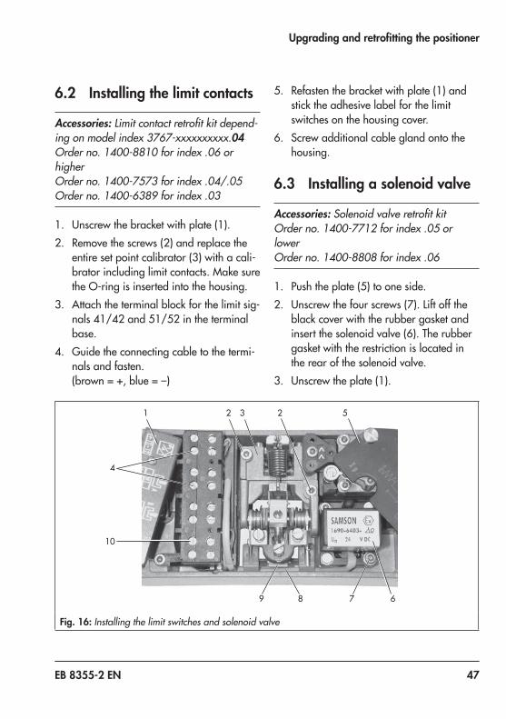
6.2 Installing the limit contacts
Accessories: Limit contact retrofit kit depend-ing on model index 3767-xxxxxxxxxx.04Order no. 1400-8810 for index .06 or higherOrder no. 1400-7573 for index .04/.05Order no. 1400-6389 for index .03
1. Unscrew the bracket with plate (1).2. Removethescrews (2)andreplacethe
entiresetpointcalibrator (3)withacali-brator including limit contacts. Make sure the O-ring is inserted into the housing.
3. Attach the terminal block for the limit sig-nals41/42and51/52intheterminalbase.
4. Guide the connecting cable to the termi-nals and fasten.(brown = +, blue = –)
5. Refasten the bracket with plate (1) and stick the adhesive label for the limit switches on the housing cover.
6. Screw additional cable gland onto the housing.
6.3 Installing a solenoid valve
Accessories: Solenoid valve retrofit kitOrder no. 1400-7712 for index .05 or lowerOrder no. 1400-8808 for index .06
1. Pushtheplate(5)tooneside.2. Unscrewthefourscrews(7).Liftoffthe
black cover with the rubber gasket and insertthesolenoidvalve(6).Therubbergasket with the restriction is located in the rear of the solenoid valve.
3. Unscrew the plate (1).
1 2 23
4
5
6789
10
Fig. 16: Installing the limit switches and solenoid valve
48 EB 8355-2 EN
Servicing explosion-protected devices
4. Attach the terminal block (10) for the so-lenoid valve in the terminal base.
5. Insertthepanel (9)attherearofthepo-sitioner and attach it to the set point cali-brator using two screws.
6. Guide the connecting cable down behind the mounted panel of the set point cali-brator and up again to terminals 81/82 and fasten.(brown = +, blue = –)
7. Screw on the bracket with plate (1).8. Screw additional cable gland onto the
housing.
6.4 Removing the solenoid valve
Accessories: Retrofit kit containing cover for solenoid valve opening: order no. 1400-6949
1. Unscrew bracket with plate (1). Remove the connecting cable of the solenoid valve from terminals 81/82.
2. Unscrewthetwoscrews(7)thatarenotsealed with paint and remove the sole-noid valve with its connecting cable.
3. Place the rubber gasket on the spigot of the cover and screw it into the housing.
4. Screw on the bracket with plate (1).
7 Servicing explosion-protected devices
If a part of the device on which the explosion protection is based needs to be serviced, the device must not be put back into operation untilaqualifiedinspectorhasassesseditac-cording to explosion protection require-ments,hasissuedaninspectioncertificateorgiven the device a mark of conformity.Inspectionbyaqualifiedinspectorisnotre-quired if the manufacturer performs a rou-tine test on the device before putting it back into operation. Document the passing of the routine test by attaching a mark of conformi-ty to the device.Replace explosion-protected components on-ly with original, routine-tested components by the manufacturer.Devices that have already been used out-side hazardous areas and are intended for future use inside hazardous areas must comply with the safety requirements placed on serviced devices. Before being operated inside hazardous areas, test the devices ac-cording to the specifications for servicing explosion-protected devices. Observe EN 60079-17 during servicing.
EB 8355-2 EN 49
Dimensions in mm
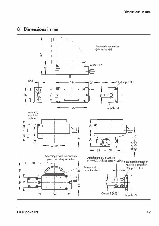
8 Dimensions in mm
44
19.5
3539
164
4676 50
36N
1=11
3 N
2=20
0
5856
68
28
1429
150
16419.5
37
6818
5
76
Ø110
82
5666
50
M20 x 1.5
28.5
28.5
Output 1 (A1)
Output 2 (A2) Supply (Z)
50
Output (38)
Supply (9)
Pneumatic connectionsG ¼or¼ NPT
Reversing amplifier(optional)
Attachment with intermediate piece for rotary actuators AttachmentIEC 60534-6
(NAMUR) with adapter housing
Fulcrum of actuator shaft
Pneumatic connection reversingamplifier
50 EB 8355-2 EN
���
Ptb16-3767.doc
�������������������������������������
�����������������������
�� ����������������
��� ���������������������� ��������
� � ����������������������������������������������������������������������
�����������������������������
��� ��� ������������������������������
���� ���������
��� �������� �������������������������
��� ������������� �������������������������������
��� �������� �����������������������������������������������
��� �������������������������������������������������������������������
�����������������������������
��� ���������������� ������������������������������������������������ �������������
���������������������������������������������� ���������������������������������
�������������������������������������������������������������������
����������������������������������������������������������������������������
�����������������������������������������������������������������������������
�����������������
��� �������������������������������������������������������������������������
���� ��������������� ���� � �����
���� ���������������������������������������������������������������������������
��������������������������������������������������������������������������������
��������������������
���� �������������������������������������������� ���������������������������������
�������������������������������������������������������������������������
�����������������������������������������������������������������������������
��������
EB 8355-2 EN 51
���
Ptb16-3767.doc
�������������������������������������
�����������������������
��� �����������������������������������������������������
���������� ����
������������������������������������ �������������������������� �
������
���������� �����
����������������������
����������������
52 EB 8355-2 EN
���
Ptb16-3767.doc
�������������������������������������
�����������������������
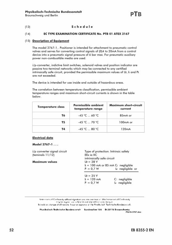
��� ��������������
��� �������������������������������������������������
��� ����������������������
�������������������������������������������������������������������������
������������������������������������������������������ ����������������������
������������������������������������������������� ���������������� ������
�����������������������������������
����������������������������������������������������������������������������������
�������������������������������������������������������������������
����������������������������������������������������� �������������� �� �������
��������� �������
��������������������������������������������������������������������
�������������������������������������������������������������������
����������������������� �����������������������������������������������
������
���������������������������������
��������������
�������������������
�����
�� ���������������� ������
�� ���������������� �������
�� ���������������� ����
��������������
������������������
���������������������������� �����������������������������������
�������������� �� �������
��������������������������
�������������� � ������
� ����������������� ����������
� ������� �� ��������������
� ������
� �������� ������� ����������
� ������� ������������������ ����������
EB 8355-2 EN 53
���
Ptb16-3767.doc
�������������������������������������
�����������������������
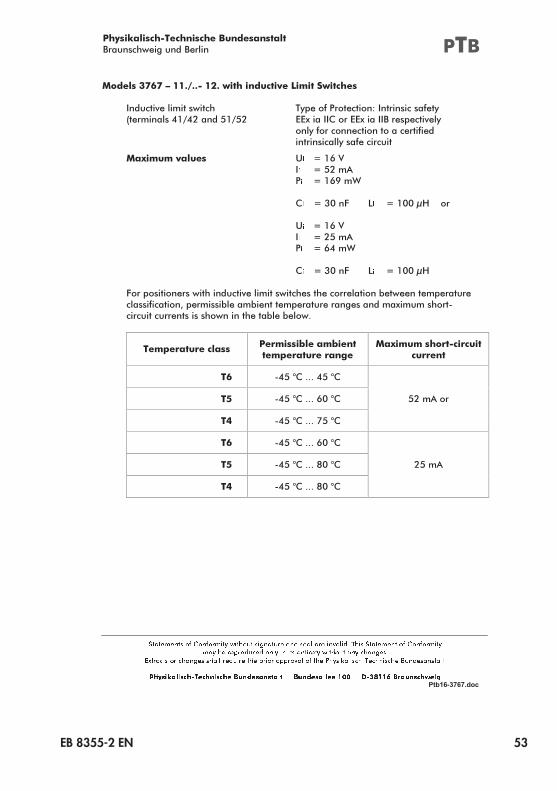
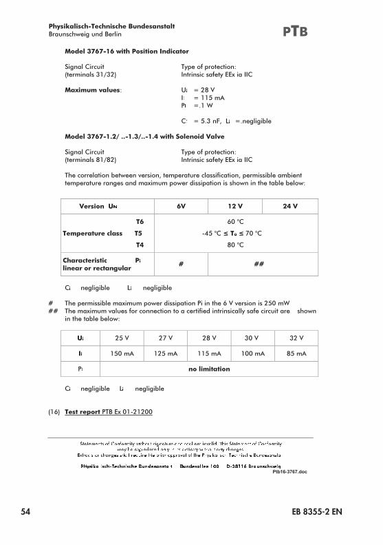
���������������������������������������������������
������������ ��������� ��������������������������������
���� ��������������������� �����������������������������������
�����������������������������
��������������������������
������������� � ��� �
� ����� �
� ��� �� �
� ������� � �������������
� ��� �
� ����� �
� �� �� �
� ������� � ��������
����������������������������� ������������������������������������ �������
����������������� ��������� �������� ������������������� ��� � ������
�������������������������������������������
������������������������������������
��������������� �
��������������������
�������
� ����������������
� ����������� ���� ��� ���
�� ����������������
� ����������� ����
� ���������������� ��� �
�� ����������������
54 EB 8355-2 EN
���
Ptb16-3767.doc
�������������������������������������
�����������������������
��������������������������������
�������������� ��������������
����������������� ��������������������������
�������������� � �����
� �������
� �����
� ����������� ������������
���������������������������������������������
�������������� ��������������
����������������� ��������������������������
��������������������������������������������������������������������������
�������������������������������������������������������������������������
���������� � ���� ����
�
��� ��������������������
��
���������������������������������
������������������������ � �����
���������������������������������
�����������������������������
���������������������
� ��
� ������������������������� ���������������
� ��������������������������������������������������� ����������������
�� ������������������������������������������������������������������������ ����
������������������
� �� ��� ��� ��� ���
� ����� ����� ����� ������ ����
� �������������
� ��������������������� ���������������
���� ������� ����� �������������
EB 8355-2 EN 55
���
Ptb16-3767.doc
�������������������������������������
�����������������������
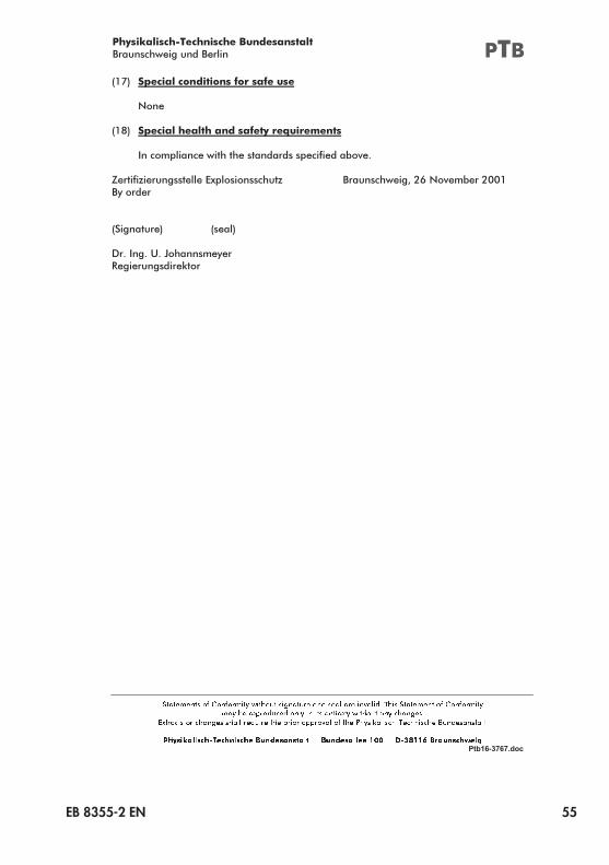
��� ���������������������������
����
�� ����������������������������������
������������������������������������������������
�������������������������������������� ��������������������������� �
�������
���������� �����
����������������������
������������������
56 EB 8355-2 EN
EB 8355-2 EN 57
58 EB 8355-2 EN
EB 8355-2 EN 59
60 EB 8355-2 EN
EB 8355-2 EN 61
62 EB 8355-2 EN
EB 8355-2 EN 63
64 EB 8355-2 EN
EB 8355-2 EN 65
66 EB 8355-2 EN
EB 8355-2 EN 67
68 EB 8355-2 EN
EB 8355-2 EN 69
70 EB 8355-2 EN
EB 8355-2 EN 71
72 EB 8355-2 EN
EB 8355-2 EN 73
74 EB 8355-2 EN

EB 8355-2 EN 75
2019
-07-12·English
SAMSON AKTIENGESELLSCHAFTWeismüllerstraße 3 · 60314 Frankfurt am Main, GermanyPhone: +49 69 4009-0 · Fax: +49 69 [email protected] · www.samson.de
EB 8355-2 EN