Embed Size (px)
Citation preview

INSTALLATION GUIDE
NI RMC-8355This guide includes installation information for the NI RMC-8355. For more information about configuring, using, and maintaining the NI RMC-8355, refer to the NI RMC-8355 User Manual. You can download the user manual in PDF format at ni.com/manuals.
ContentsRelated Documentation ............................................................................................................ 2Unpacking................................................................................................................................. 3What You Need to Get Started ................................................................................................. 3Key Features ............................................................................................................................. 4
Mainboard Features .......................................................................................................... 4CPU .......................................................................................................................... 4Chipset ...................................................................................................................... 4Memory .................................................................................................................... 4Slots .......................................................................................................................... 4Video ........................................................................................................................ 4HDD.......................................................................................................................... 4DVD-R/W................................................................................................................. 4Onboard LAN........................................................................................................... 4Onboard I/O.............................................................................................................. 5Power Supply............................................................................................................ 5Fan ............................................................................................................................ 5Power Management Features.................................................................................... 5Front Panel LEDs ..................................................................................................... 5System Management................................................................................................. 5
NI RMC-8355 Description ....................................................................................................... 6Upgrade/Optional Equipment................................................................................................... 7
Memory Upgrades ............................................................................................................ 7Upgrade Options............................................................................................................... 7
NI RMC-8355 Overview .......................................................................................................... 8Safety Information.................................................................................................................... 8Chassis Cooling Considerations ............................................................................................... 9
Providing Adequate Clearance ......................................................................................... 9Installation ................................................................................................................................ 9Installing the LabVIEW Real-Time Module ............................................................................ 10NI RMC-8355 Mounting Brackets ........................................................................................... 12Cable Retention Bracket ........................................................................................................... 13Connecting Safety Ground ....................................................................................................... 13Connecting to Power Source .................................................................................................... 13

2 | ni.com | NI RMC-8355 Installation Guide
Rack Mounting .........................................................................................................................14Installing the Inner Slides .................................................................................................14Installing the Slide Mounting Brackets in the Rack .........................................................15Installing the Outer Slides in the Rack .............................................................................16Installing the Chassis into the Rack..................................................................................17
OS Reinstallation and Recovery ...............................................................................................17Cleaning ....................................................................................................................................18
Exterior Cleaning.............................................................................................................. 18Specifications............................................................................................................................18
Electrical ...........................................................................................................................18AC Input ...................................................................................................................18DC Input ...................................................................................................................19
Mainboard .........................................................................................................................19CPU...................................................................................................................................20Hard Disk Drive................................................................................................................ 20Memory.............................................................................................................................20Mechanical........................................................................................................................20Shock and Vibration .........................................................................................................21
Operational Random.................................................................................................21Non-Operational Random.........................................................................................21Random Vibration Test Procedures ..........................................................................21
Environmental...................................................................................................................22Acoustic Emissions...........................................................................................................22Safety ................................................................................................................................22Electromagnetic Compatibility .........................................................................................23CE Compliance .................................................................................................................23Online Product Certification.............................................................................................23Environmental Management.............................................................................................23
Worldwide Support and Services .............................................................................................24
Related DocumentationThe following documents contain information that you may find helpful as you read this manual:
• CompactPCI Specification PICMG 2.0 R 3.0
• PXI Hardware Specification, Revision 2.1
• PXI Software Specification, Revision 2.1
• ANSI/IEEE Standard 1014-1987, IEEE Standard for a Versatile Backplane Bus: VMEbus
• ANSI/VITA 1-1994, VME64
• NI-VISA User Manual
• NI-VISA Programmer Reference Manual
• Read Me First: Safety and Electromagnetic Compatibility, National Instruments

NI RMC-8355 Installation Guide | © National Instruments | 3
UnpackingCarefully inspect the shipping container and the NI RMC-8355 for damage. Check for visible damage to the metal work. Check to make sure all hardware and switches are undamaged. If damage appears to have been caused during shipment, file a claim with the carrier. Retain the packing material for possible inspection and/or reshipment.
What You Need to Get StartedThe NI RMC-8355 kit contains the following items:
NI RMC-8355 rack mount controller
NI RMC-8355 User Manual
Windows recovery CD/DVD (not included in the RT version)
Bracket for rear cable retention
AC power cable (refer to Table 1 for a list of AC power cables)
23-36 VDC 3-pin connector (ships with the DC option)
The unit comes with the standard 120 V (USA) cable. If you have the incorrect AC power cable, contact National Instruments.
Table 1. AC Power Cables
Power Cable Reference Standards
Standard 120 V (USA) ANSI C73.11/NEMA 5-15-P/IEC83
Switzerland 220 V SEV
Australia 240 V AS C112
Universal Euro 230 V CEE (7), II, IV, VII IEC83
North America 240 V ANSI C73.20/NEMA 5-15-P/IEC83
United Kingdom 230 V BS 1363/IEC83
Japan 100 V ANSI C73.11/NEMA 5-15-P/IEC83

4 | ni.com | NI RMC-8355 Installation Guide
Key FeaturesThe NI RMC-8355 offers the performance of a high-end PC in a compact 1U rack-mountable form factor for controlling a PXI or PXI Express system using a National Instruments remote controller.
Mainboard Features
CPU• Dual Intel Xeon E5620 2.4 GHZ, 80 W, LGA1366 (second processor optional upgrade)
Chipset• Intel 5520 chipset, including the 5520 (North Bridge) and ICH10R (South Bridge)
Memory• 3 GB RDIMM ECC DDR3 memory standard (3 × 1 GB)
• Maximum memory supported: 48 GB registered ECC DDR3-800/1066 in 6 DIMM sockets (per processor)
Slots• One PCI Express 2.0 x16 slot
• One PCI Express 2.0 x8 slot (requires a custom PCI Express bracket)
Note The x8 bottom slot requires a custom bracket and supports only half-height cards.
Video• Matrox G200eW 16 MB DDR2 (max resolution 1280 × 1024)
HDD• 1 × 500 GB or 2 × 500 GB SATA (3 Gbps) hard drive JBOD/RAID0/1
• Upgrade option: 1 × 300 GB or 2 × 300 GB SATA (3 Gbps) SSD JBOD/RAID0/1
DVD-R/W• Front removable slim slot load DVD-R/W drive
Onboard LAN• 2 × Intel 82576 Gigabit Ethernet controller

NI RMC-8355 Installation Guide | © National Instruments | 5
Onboard I/O• PS/2 keyboard port
• PS/2 mouse port
• Serial port
• VGA port
• Two USB 2.0 ports (rear)
• Two USB 2.0 ports (front)
• Two RJ-45 ports
Power Supply• Supports redundant AC and DC power supplies
Fan• Accessible and hot swappable fans
Power Management Features• ACPI/ACPM power management
• Main switch override mechanism
• Wake-On-LAN (WOL) header
• Wake up on keyboard/mouse from Soft-Off
• Power-on mode from AC power recovery
Front Panel LEDs• Power indicator
• Power shuttle indicators
• LAN status indicators
• HDD indicator
• System temp (overheat) and fan (fail) warning indicator
System Management• Monitoring for CPU and chassis environment
• CPU thermal trip support
• +5 V standby alert LED
• Fan speed control

6 | ni.com | NI RMC-8355 Installation Guide
NI RMC-8355 DescriptionFigure 1 shows the key features of the NI RMC-8355 front panel. For detailed information about the NI RMC-8355 rear panel, refer to Chapter 3, I/O Information, in the NI RMC-8355 User Manual.
Figure 1. Front View of the NI RMC-8355
The front panel includes the following LEDs:
• Hard drive activity indicator—glows when there is hard drive activity.
• Power shuttle indicators—glow when power shuttles are powered on.
• LAN status indicators—flash when there is activity on LAN1 or LAN2.
• Overheat/fan fail indicator
– Off—Normal
– On—Overheat
– Flashing—Fan failure warning
• Power indicator—glows when the NI RMC-8355 is powered on.
1 DVD R/W Drive2 Hard Drives3 Hard Drive Ejector Buttons4 USB Ports5 Hard Drive Activity Indicator6 Power Shuttle 1 Indicator
7 Power Shuttle 2 Indicator8 LAN1 Status Indicator9 LAN2 Status Indicator10 System Temp and Fan Warning Indicator11 Power Indicator12 Power Switch
4122
1
3 32
98765 10 11

NI RMC-8355 Installation Guide | © National Instruments | 7
Upgrade/Optional Equipment
Memory UpgradesYou can upgrade the NI RMC-8355 memory to a maximum of 96 GB (48 GB per processor).
Note A 32-bit operating system such as Windows XP Pro addresses a maximum of 4 GB.
The NI RMC-8355 supports tri-channel DDR-3 SDRAM registered memory in four 240-pin RDIMM sockets. The NI RMC-8355 is compatible with ECC memory.
Note Supported RDIMM sizes are 1 GB, 4 GB, and 8 GB.
Note National Instruments has tested and verified that the DDR-3 RDIMMs we offer work with the NI RMC-8355. We recommend you purchase your DDR-3 RDIMM modules from National Instruments. Other off-the-shelf DDR-3 RDIMM modules are not guaranteed to work properly.
Upgrade OptionsTable 2 lists upgrade options available for the NI RMC-8355.
Table 2. NI RMC-8355 Upgrade Options
Orderable P/N Description
782116-01 Spare optical drive for NI RMC-8355
783524-01 Spare/replacement Blu-ray disk drive for NI RMC-8355
782117-01 Spare 250 GB SSD and drive bay for NI RMC-8355
782314-01 Spare 500 GB HDD and drive bay for NI RMC-8355
782301-01 PCI Express plug-in video card with dual digital display outputs
782302-01 Rack mount rails for NI RMC-8355
782544-01 Spare/replacement AC power supply for NI RMC-8355
782545-01 Spare/replacement DC power supply for NI RMC-8355
782547-01 DC power cable for NI RMC-8355
782546-01 Spare/replacement fan for NI RMC-8355
782567-1024 1 GB RAM replacement/upgrade for NI RMC-8355
782567-4096 4 GB RAM replacement/upgrade for NI RMC-8355
782567-8192 8 GB RAM replacement/upgrade for NI RMC-8355
782596-01 Dual CPU Upgrade, Intel Xeon E5620

8 | ni.com | NI RMC-8355 Installation Guide
NI RMC-8355 OverviewThe NI RMC-8355 is a rugged 1U PC-based controller for remote control of PXI chassis. The controller provides leading-edge processing power with Intel Xeon 5620 processors, high disk bandwidth with hardware RAID support, high I/O bandwidth with a PCI Express 2.0 x16 and x8 slot, and up to 48 GB of RDIMM ECC memory per processor.
Safety Information
Caution Before undertaking any troubleshooting, maintenance, or exploratory procedure, carefully read the following caution notices.
Caution Product functionality can be disrupted if the knurled thumbscrews on the back of the top cover are subjected to Electrostatic Discharge (ESD). To prevent damage, you must employ industry-standard ESD prevention measures during installation, maintenance, and operation.
Caution Overloading the circuits may damage supply wiring. Do not exceed the ratings on the equipment nameplate when connecting equipment to the supply circuit.
Note Tighten the thumbscrew for the top panel cover with a tool after both initial installation and subsequent access.
Caution To avoid risk of explosion, do not replace the battery (JBAT1) with an incorrect battery type. Dispose of used batteries according to the battery instructions.
This equipment contains voltage hazardous to human life and safety, and is capable of inflicting personal injury.
• Chassis Grounding—The NI RMC-8355 requires a connection from the premise wire safety ground to the NI RMC-8355 chassis ground. The earth safety ground must be connected during use of this equipment to minimize shock hazards. Refer to the Connecting Safety Ground section for instructions on connecting safety ground.
• Mechanical Loading—To avoid a hazardous load condition, be sure the mechanical load is even when rack mounting the equipment.
• Live Circuits—Operating personnel and service personnel must not remove protective covers when operating or servicing the NI RMC-8355. Adjustments and service to internal components must be undertaken by qualified service technicians. During service of this product, the mains connector to the premise wiring must be disconnected. Dangerous voltages may be present under certain conditions; use extreme caution.
• Explosive Atmosphere—Do not operate the chassis in conditions where flammable gases are present. Under such conditions, this equipment is unsafe and may ignite the gases or gas fumes.
NI RMC-8355 Installation Guide | © National Instruments | 9
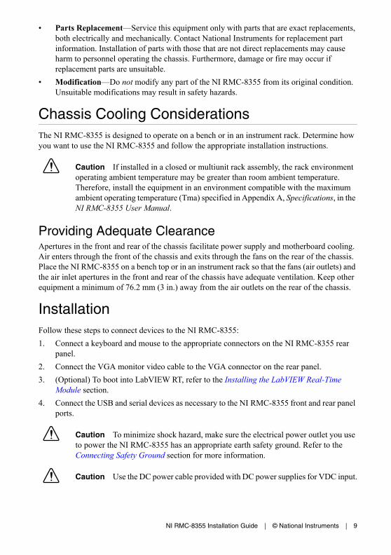
• Parts Replacement—Service this equipment only with parts that are exact replacements, both electrically and mechanically. Contact National Instruments for replacement part information. Installation of parts with those that are not direct replacements may cause harm to personnel operating the chassis. Furthermore, damage or fire may occur if replacement parts are unsuitable.
• Modification—Do not modify any part of the NI RMC-8355 from its original condition. Unsuitable modifications may result in safety hazards.
Chassis Cooling ConsiderationsThe NI RMC-8355 is designed to operate on a bench or in an instrument rack. Determine how you want to use the NI RMC-8355 and follow the appropriate installation instructions.
Caution If installed in a closed or multiunit rack assembly, the rack environment operating ambient temperature may be greater than room ambient temperature. Therefore, install the equipment in an environment compatible with the maximum ambient operating temperature (Tma) specified in Appendix A, Specifications, in the NI RMC-8355 User Manual.
Providing Adequate ClearanceApertures in the front and rear of the chassis facilitate power supply and motherboard cooling. Air enters through the front of the chassis and exits through the fans on the rear of the chassis. Place the NI RMC-8355 on a bench top or in an instrument rack so that the fans (air outlets) and the air inlet apertures in the front and rear of the chassis have adequate ventilation. Keep other equipment a minimum of 76.2 mm (3 in.) away from the air outlets on the rear of the chassis.
InstallationFollow these steps to connect devices to the NI RMC-8355:
1. Connect a keyboard and mouse to the appropriate connectors on the NI RMC-8355 rear panel.
2. Connect the VGA monitor video cable to the VGA connector on the rear panel.
3. (Optional) To boot into LabVIEW RT, refer to the Installing the LabVIEW Real-Time Module section.
4. Connect the USB and serial devices as necessary to the NI RMC-8355 front and rear panel ports.
Caution To minimize shock hazard, make sure the electrical power outlet you use to power the NI RMC-8355 has an appropriate earth safety ground. Refer to the Connecting Safety Ground section for more information.
Caution Use the DC power cable provided with DC power supplies for VDC input.

10 | ni.com | NI RMC-8355 Installation Guide
5. Connect the AC power cable to the AC inlet on the rear panel and to an AC power outlet. For more information, refer to the Connecting to Power Source section.
6. For the DC option, connect the DC positronic connector to the DC inlet on the rear panel and wire to a DC power source.
7. Power on the NI RMC-8355.
8. Verify that the NI RMC-8355 boots. If it does not boot, refer to the What if the NI RMC-8355 does not boot? section of Chapter 5, Troubleshooting, in the NI RMC-8355 User Manual.
Installing the LabVIEW Real-Time ModuleThis section explains software installation for the LabVIEW Real-Time Module on your NI RMC-8355, including the necessary steps to set up your NI RMC-8355 to run the LabVIEW Real-Time Module.
Note The onboard Ethernet ports on the NI RMC-8355 do not work with the LabVIEW Real-Time Module. You must use the PCI Express Ethernet board preinstalled in your system.
Complete the following steps to install the LabVIEW Real-Time Module software.
1. Boot the NI RMC-8355 into the real-time operating system using the USB RT key in the accessory box. Complete the following steps once the system boots into the Desktop PC Utility:
a. Select Available Actions»Format»Format Hard disk options.
b. Select (2) Erase all partitions.
c. Select FAT.
d. Type Yes to start formatting the hard disk.
e. Once the format completes, return to the boot menu and select Boot into safe mode.
f. Remove the USB key from the NI RMC-8355.
The RMC automatically boots into LabVIEW Real-Time Module Safe Mode when no software is installed. Safe Mode loads with the basic real-time operating system and automatically attempts to connect to the network using DHCP. If DHCP is not available, the controller connects to the network with a link-local IP address.
Note The remote system must have an IP address assigned to it before you can perform any additional configuration.
2. Open Measurement & Automation Explorer (MAX) on another computer in the same subnet and expand the Remote Systems branch. MAX lists the RMC as NI-GenericDesktopPC followed by the MAC address
Note The other computer must have LabVIEW, the LabVIEW Real-Time Module, and any desired drivers installed.

NI RMC-8355 Installation Guide | © National Instruments | 11
3. Click the appropriate entry to access the Network Settings tab in the right pane view. If the remote system is not already configured to obtain an IP address automatically, use the Network Settings tab to either manually specify an IP address or obtain one automatically.
4. (Optional) Enter a name for the RT target in the Name text box.
5. (Optional) Set the network configuration options of the RT target in the IP Settings section and click the Apply button.
For information about configuring network settings, refer to the Configuring Network Settings book, accessible by browsing to MAX Remote Systems Help»LabVIEW Real-Time Target Configuration»Configuring Network Settings from the Contents tab of MAX Help.
Note When any IP or identification settings are changed, you are prompted to reboot the controller for the changes to take effect. Click Yes to reboot the RT target automatically. You may also reboot the controller by right-clicking the target name under Remote Systems and selecting Reboot.
After rebooting the NI RMC-8355, it appears in the Remote Systems category with the assigned name.
6. Expand the NI RMC-8355 view in the Remote Systems branch and select Software.
7. Click the Add/Remove Software button in the toolbar to launch the LabVIEW Real-Time Software Wizard.
8. Install the LabVIEW Real-Time Module software and device drivers you require on the RT target. Refer to the National Instruments website at ni.com/info and enter the Info Code etspc for the latest information about supported software.
After installation of the software, the NI RMC-8355 automatically reboots. You now can program it using the LabVIEW Real-Time Module.
Tip Refer to the Getting Started with the LabVIEW Real-Time Module, available on your host computer, for more information about setting up your RT target.

12 | ni.com | NI RMC-8355 Installation Guide
NI RMC-8355 Mounting BracketsThe NI RMC-8355 includes the mounting brackets shown in Figure 2. For mounting instructions, refer to NI KnowledgeBase 6D8A2IBD on ni.com.
Figure 2. NI RMC-8355 Mounting Brackets
NI P/N 154952A-01for NI PCIe-8375
NI P/N 154903A-01for NI PCIe-8381
NI P/N 154902A-01for NI PCIe-8371
NI P/N 155882A-01for NI PCIe-8362

NI RMC-8355 Installation Guide | © National Instruments | 13
Cable Retention BracketThe NI RMC-8355 includes a cable retention bracket. Install the bracket with the retaining screws, as shown in Figure 3.
Figure 3. Cable Retention Bracket
Connecting Safety GroundThe NI RMC-8355 is designed with a three-position NEMA 5-15 style plug for the U.S. that connects the ground line to the chassis ground. To minimize shock hazard, make sure the electrical power outlet you use to power the chassis has an appropriate earth safety ground.
Note The NI RMC-8355 also includes a grounding screw (8-32 thread size nut) on the back of the chassis. (The nut is not supplied with the NI RMC-8355.)
Connecting to Power SourceAttach input power through the rear AC/DC inlet using the appropriate AC/DC power cable supplied.
Caution Overloading the circuits may damage supply wiring. Do not exceed the ratings on the equipment nameplate when connecting equipment to the supply circuit.
Caution To completely remove power, you must disconnect the AC/DC power cable.
Caution For a DC power supply, provide a 20 A max overcurrent protection device external to the equipment.
The power switch allows you to power on the chassis or place it in standby mode. Push the power switch to the On position (if not already on). Observe that all fans become operational and the power indicator is lit.
1 Retaining Screw (x2) 2 Cable Retention Bracket
1
2

14 | ni.com | NI RMC-8355 Installation Guide
Rack Mounting
Caution When mounting the equipment in the rack, do not create a hazardous condition due to uneven mechanical loading.
The NI RMC-8355 rack mounting hardware includes:
• One pair of inner slides to be installed on the chassis.
• One pair of outer slides to be installed in the rack.
• Two pairs of brackets (4 in. and 12 in.) for attaching the outer slides to racks of different depths.
• Bag of assorted fasteners.
Installing the Inner SlidesInstall the inner slides to the NI RMC-8355 as shown in Figure 4.
Figure 4. Installing Inner Slides
1 Retaining Screw (x14) 2 Inner Slide
1
2

NI RMC-8355 Installation Guide | © National Instruments | 15
Installing the Slide Mounting Brackets in the RackInstall the slide mounting brackets in the rack as shown in Figure 5.
Figure 5. Installing Slide Mounting Brackets in Rack
1 Retaining Screw (x4)2 Slide Mounting Bracket (x4)
3 Washer (x8)4 Nut (x4)
1
2 4
3

16 | ni.com | NI RMC-8355 Installation Guide
Installing the Outer Slides in the RackInstall the outer slides in the rack as shown in Figure 6.
Figure 6. Installing Outer Slides in Rack
1 Nut (x6) 2 Outer Slide 3 Retaining Screw (x6)
2
3
1

NI RMC-8355 Installation Guide | © National Instruments | 17
Installing the Chassis into the RackPush the inner slides, attached to the chassis, into the grooves of the outer slides in the rack and slide the NI RMC-8355 into the rack, as shown in Figure 7.
Figure 7. Installing NI RMC-8355 in Rack
OS Reinstallation and Recovery
Caution Recovering the OS using the hard drive-based recovery or the OS recovery CD/DVD erases the contents of your hard disk. Before recovering the OS, back up any files you want to keep.
The NI RMC-8355 includes a preinstalled OS from the factory. The NI RMC-8355 also includes two methods of restoring/reinstalling the OS to your system.
• Hard drive-based recovery stores a factory backup on a separate portion of your hard drive, allowing you to restore your server without additional media.
Note The hard drive recovery hot key is <F4>. To access the hard drive-based recovery tool, press and hold <F4> when video first appears during the boot process.
• The NI RMC-8355 also ships with an OS recovery CD/DVD you can use to reinstall your operating system onto your hard drive.
If you need to reinstall your operating system, you can use the included OS recovery CD/DVD. Boot the NI RMC-8355 using the OS recovery CD/DVD to recover the OS.

18 | ni.com | NI RMC-8355 Installation Guide
Note You also may need to update or reinstall software after using the OS reinstallation CD/DVD to recover your OS. The OS reinstallation CD/DVD may contain drivers that are older or newer than the factory-installed version of the OS and may not contain the latest RAID drivers. To ensure you have the latest drivers, go to www.intel.com and install the Intel Rapid Storage Technology (Intel RST) RAID software package.
Note After you reinstall or recover your OS, you may find shortcuts on the desktop that require you to install specific drivers or software (for example, video drivers). Due to driver and software packaging, it was not possible to preinstall this software during the OS installation.
Cleaning
Caution Always disconnect the AC/DC power cable before cleaning or servicing the chassis.
Exterior Cleaning
Cautions Avoid getting moisture inside the chassis during exterior cleaning, especially through the top vents.
Do not wash the front- or rear-panel connectors or switches. Cover these components while cleaning the chassis.
Do not use harsh chemical cleaning agents; they may damage the chassis. Avoid chemicals that contain benzene, toluene, xylene, acetone, or similar solvents.
Clean the exterior surfaces of the chassis with a dry lint-free cloth or a soft-bristle brush. Do not use abrasive compounds on any part of the chassis.
SpecificationsThis section lists the NI RMC-8355 electrical, mechanical, and environmental specifications.
Electrical
AC InputInput voltage range ...........................................100-240 VAC
Operating voltage range....................................90-264 VAC
Input frequency .................................................50/60 Hz
Operating frequency range................................47-63 Hz

NI RMC-8355 Installation Guide | © National Instruments | 19
Current rating.................................................... 4-2 A max (480 W max single power supply)
Power disconnect .............................................. The AC power cable provides main power disconnect. Depressing the front panel power switch enables or inhibits the internal power supply.
DC InputInput.................................................................. 23-36 V, 16-8 A ±10%
Current rating.................................................... +12 V, -41 A+5 VSB 0-3 A
DC output ......................................................... 360 W (max)
Note The connection to a DC mains supply is considered an energy hazard and must not be in an operator access area. The DC product must be located in a Restricted Access Location.
Caution Use the DC power cable provided with DC power supplies for VDC input.
Caution Using the NI RMC-8355 in a manner not described in this document may impair the protection the NI RMC-8355 provides.
MainboardSocket ............................................................... LGA 1366 (dual socket)
Chipset .............................................................. Intel 5520 chipset
Memory slots .................................................... Twelve 240-pin DIMM DDR3 slots, three channel 800/1066 96 GB max memory (six slots and 48 GB per processor)
PCI Express ...................................................... One PCI Express 2.0 x16 slot and one PCI Express 2.0 x8 slot
SATA................................................................. Two SATA ports compliant with the Serial-ATA 2.0 specification.
USB ports ......................................................... Four USB 2.0 ports
Keyboard .......................................................... PS/2 keyboard port
Mouse ............................................................... PS/2 mouse port
Video................................................................. VGA port, onboard Matrox G200eW 16 MB DDR2 (max resolution 1280 × 1024)
Serial ................................................................. One RS-232 serial port
LAN .................................................................. Two RJ45 LAN jacks
Onboard LAN controller .................................. Intel 82576 Dual-Port Gigabit Ethernet controller

20 | ni.com | NI RMC-8355 Installation Guide
CPUCPU...................................................................Xeon E5620 Quad Core
Clock speed.......................................................2.40 GHz
Max turbo frequency.........................................2.66 GHz
Intel Smart Cache..............................................12 MB
Package .............................................................LGA 1366
Hard Disk DriveCapacity ............................................................300 (SSD)/500 (HDD) GB in one or two-drive
configurations for maximum capacity of 600 GB/1 TB
Interface ............................................................Serial-ATA 2 (3 Gbps via ICH10R controller)
MemoryStandard memory ..............................................1 GB (128 M × 72 bit), DDR-III SDRAM,
RDIMM ECC 800/1066 MHz
4 GB memory upgrade (64-bit OS) ..................4 GB (128 M × 72 bit), DDR-III SDRAM, RDIMM ECC 800/1066 MHz
8 GB memory upgrade (64-bit OS) ..................8 GB (512 M × 72 bit), DDR-III SDRAM, RDIMM ECC 800/1066 MHz
Notes Six memory slots per CPU.
Maximum RAM per CPU is 48 GB (6 × 8 GB).
Standard shipping memory is 3 GB per CPU (3 × 1 GB).
MechanicalOverall dimensions (standard chassis)
Height........................................................1U
Width.........................................................432 mm (17.0 in.)
Depth.........................................................533 mm (21.0 in.)
Weight ...............................................................8.1 kg (17.8 lbs)

NI RMC-8355 Installation Guide | © National Instruments | 21
Shock and Vibration
Operational Random
Non-Operational Random
Random Vibration Test Procedures
Mechanical Shock
Operating 30 g, 11 ms
Test Procedures Standard
Operating IEC 68-2-27
Non-operating IEC 68-2-27
Frequency (Hz) Vibration Level
5-350 0.0002 g2/Hz
350-500 -3 dB/octave
500 0.00014 g2/Hz
Total grms = 0.31
Frequency (Hz) Vibration Level
5-100 0.02 g2/Hz
100-200 -3 dB/octave
200-350 0.01 g2/Hz
350-500 -3 dB/octave
500 0.007 g2/Hz
Total grms = 2.46
Test Standard
Operating IEC 68-2-64
Non-operating IEC 68-2-64

22 | ni.com | NI RMC-8355 Installation Guide
Environmental
Caution If installed in a closed or multiunit rack assembly, the rack environment operating ambient temperature may be greater than room ambient temperature. Therefore, install the equipment in an environment compatible with the maximum ambient temperature (Tma) the manufacturer specifies.
Operating temperature (Single Xeon)...............0 to 50 °C (CPU turbo mode off)(Tested in accordance with IEC-60068-2-1.)
Operating temperature (Single Xeon)...............0 to 45 °C (CPU turbo mode on)(Tested in accordance with IEC-60068-2-1.)
Operating temperature (Dual Xeon) .................0 to 45 °C (CPU turbo mode off)(Tested in accordance with IEC-60068-2-1.)
Operating temperature (Dual Xeon) .................0 to 40 °C (CPU turbo mode on) (Tested in accordance with IEC-60068-2-1.)
Storage temperature ..........................................-40 to 70 °C(Tested in accordance with IEC-60068-2-1 and IEC-60068-2-2.)
Relative humidity (tested in accordance with IEC-60068-2-56)
Operating ..................................................10 to 90% noncondensing
Nonoperational (storage) ..........................5 to 95% noncondensing
Operating location.............................................Indoor use only
Maximum altitude.............................................3,000 m
Installation Category.........................................II
Pollution Degree ...............................................2
Acoustic EmissionsSound pressure level (at operator position)
Minimum ..................................................56.3 dBA
Maximum..................................................67.2 dBA
Sound power
Minimum ..................................................62.1 dBA
Maximum..................................................73.8 dBA
SafetyThis product is designed to meet the requirements of the following standards of safety for information technology equipment:
• IEC 60950-1, EN 60950-1
• UL 60950-1, CSA 60950-1

NI RMC-8355 Installation Guide | © National Instruments | 23
Caution Overloading the circuits may damage supply wiring. Do not exceed the ratings on the equipment nameplate when connecting equipment to the supply circuit.
Note For UL and other safety certifications, refer to the product label or the Online Product Certification section.
Electromagnetic CompatibilityThis product meets the requirements of the following EMC standards for electrical equipment for measurement, control, and laboratory use:
• EN 61326 (IEC 61326): Class A emissions; Basic immunity
• EN 55011 (CISPR 11): Group 1, Class A emissions
• AS/NZS CISPR 11: Group 1, Class A emissions
• FCC 47 CFR Part 15B: Class A emissions
• ICES-001: Class A emissions
Note For the standards applied to assess the EMC of this product, refer to the Online Product Certification section.
Note For EMC compliance, operate this device with shielded cabling.
CE ComplianceThis product meets the essential requirements of applicable European Directives as follows:
• 2006/95/EC; Low-Voltage Directive (safety)
• 2004/108/EC; Electromagnetic Compatibility Directive (EMC)
Online Product CertificationRefer to the product Declaration of Conformity (DoC) for additional regulatory compliance information. To obtain product certifications and the DoC for this product, visit ni.com/certification, search by model number or product line, and click the appropriate link in the Certification column.
Environmental ManagementNI is committed to designing and manufacturing products in an environmentally responsible manner. NI recognizes that eliminating certain hazardous substances from our products is beneficial to the environment and to NI customers.
For additional environmental information, refer to the Minimize Our Environmental Impact web page at ni.com/environment. This page contains the environmental regulations and directives with which NI complies, as well as other environmental information not included in this document.

© 2012–2014 National Instruments. All rights reserved.
373830C-01 Mar14
Refer to the NI Trademarks and Logo Guidelines at ni.com/trademarks for more information on National Instruments trademarks. Other product and company names mentioned herein are trademarks or trade names of their respective companies. For patents covering National Instruments products/technology, refer to the appropriate location: Help»Patents in your software, the patents.txt file on your media, or the National Instruments Patents Notice at ni.com/patents. You can find information about end-user license agreements (EULAs) and third-party legal notices in the readme file for your NI product. Refer to the Export Compliance Information at ni.com/legal/export-compliance for the National Instruments global trade compliance policy and how to obtain relevant HTS codes, ECCNs, and other import/export data.
Waste Electrical and Electronic Equipment (WEEE)EU Customers At the end of the product life cycle, all products must be sent to a WEEE recycling center. For more information about WEEE recycling centers, National Instruments WEEE initiatives, and compliance with WEEE Directive 2002/96/EC on Waste and Electronic Equipment, visit ni.com/environment/weee.
Battery Replacement and DisposalBattery Directive This device contains a long-life coin cell battery. If you need to replace it, use the Return Material Authorization (RMA) process or contact an authorized National Instruments service representative. For more information about compliance with the EU Battery Directive 2006/66/EC about Batteries and Accumulators and Waste Batteries and Accumulators, visit ni.com/environment/batterydirective.
Worldwide Support and ServicesThe National Instruments website is your complete resource for technical support. At ni.com/support you have access to everything from troubleshooting and application development self-help resources to email and phone assistance from NI Application Engineers.
Visit ni.com/services for NI Factory Installation Services, repairs, extended warranty, and other services.
Visit ni.com/register to register your National Instruments product. Product registration facilitates technical support and ensures that you receive important information updates from NI.
National Instruments corporate headquarters is located at 11500 North Mopac Expressway, Austin, Texas, 78759-3504. National Instruments also has offices located around the world. For telephone support in the United States, create your service request at ni.com/support or dial 1 866 ASK MYNI (275 6964). For telephone support outside the United States, visit the Worldwide Offices section of ni.com/niglobal to access the branch office websites, which provide up-to-date contact information, support phone numbers, email addresses, and current events.
Cd/Hg/Pb
RoHSNational Instruments
(RoHS) National Instruments RoHS ni.com/environment/rohs_china (For information about China RoHS compliance, go to ni.com/environment/rohs_china.)