Embed Size (px)
DESCRIPTION
User’s and Programmer’s ReferenceVolume 1Core Spectrum Analyzer FunctionsPSA Series Spectrum Analyzers
Citation preview
User’s and Programmer’s ReferenceVolume 1
Core Spectrum Analyzer Functions
PSA Series Spectrum AnalyzersRefer to Volume 2 for one-button power measurements information.
This manual provides documentation for the following instruments:
Agilent Technologies PSA Series
E4440A (3 Hz - 26.5 GHz)E4443A (3 Hz - 6.7 GHz)
E4445A (3 Hz - 13.2 GHz) E4446A (3 Hz - 44.0 GHz)
E4447A (3 Hz - 42.98 GHz) E4448A (3 Hz - 50.0 GHz)
Manufacturing Part Number: E4440-90607Supersedes: Jume 2008
Printed in USASeptember 2011
© Copyright 2001-2011 Agilent Technologies, Inc.

Legal InformationThe information contained in this document is subject to change without notice.
Agilent Technologies makes no warranty of any kind with regard to this material, including but not limited to, the implied warranties of merchantability and fitness for a particular purpose. Agilent Technologies shall not be liable for errors contained herein or for incidental or consequential damages in connection with the furnishing, performance, or use of this material.
Where to Find the Latest Information
Documentation is updated periodically.
• For the latest information about Agilent Technologies PSA Spectrum Analyzers, including firmware upgrades and application information, please visit the following Internet URL:
http://www.agilent.com/find/psa
• To receive the latest updates by email, subscribe to Agilent Email Updates:
http://www.agilent.com/find/emailupdates
• Information on preventing spectrum analyzer damage can be found at:
http://www.agilent.com/find/tips
2
ContentsTable of C
ontents
1. Using This DocumentAbout the User’s and Programmer’s Information. . . . . . . . . . . . . . . . . . . . . . . . . . . . . . . . . . . . . . . . . . . . . 30
What is in This Book. . . . . . . . . . . . . . . . . . . . . . . . . . . . . . . . . . . . . . . . . . . . . . . . . . . . . . . . . . . . . . . . . 30Terms Used in This Book . . . . . . . . . . . . . . . . . . . . . . . . . . . . . . . . . . . . . . . . . . . . . . . . . . . . . . . . . . . . . 31
2. Instrument Functions: A − LAMPLITUDE / Y Scale . . . . . . . . . . . . . . . . . . . . . . . . . . . . . . . . . . . . . . . . . . . . . . . . . . . . . . . . . . . . . . . . 35
Ref Level . . . . . . . . . . . . . . . . . . . . . . . . . . . . . . . . . . . . . . . . . . . . . . . . . . . . . . . . . . . . . . . . . . . . . . . . . 35Attenuation . . . . . . . . . . . . . . . . . . . . . . . . . . . . . . . . . . . . . . . . . . . . . . . . . . . . . . . . . . . . . . . . . . . . . . . . 36Scale/Div . . . . . . . . . . . . . . . . . . . . . . . . . . . . . . . . . . . . . . . . . . . . . . . . . . . . . . . . . . . . . . . . . . . . . . . . . 37Scale Type . . . . . . . . . . . . . . . . . . . . . . . . . . . . . . . . . . . . . . . . . . . . . . . . . . . . . . . . . . . . . . . . . . . . . . . . 38Presel Center . . . . . . . . . . . . . . . . . . . . . . . . . . . . . . . . . . . . . . . . . . . . . . . . . . . . . . . . . . . . . . . . . . . . . . 38Presel Adjust . . . . . . . . . . . . . . . . . . . . . . . . . . . . . . . . . . . . . . . . . . . . . . . . . . . . . . . . . . . . . . . . . . . . . . 40Y Axis Units . . . . . . . . . . . . . . . . . . . . . . . . . . . . . . . . . . . . . . . . . . . . . . . . . . . . . . . . . . . . . . . . . . . . . . . 42Ref Lvl Offset . . . . . . . . . . . . . . . . . . . . . . . . . . . . . . . . . . . . . . . . . . . . . . . . . . . . . . . . . . . . . . . . . . . . . . 46Int Preamp . . . . . . . . . . . . . . . . . . . . . . . . . . . . . . . . . . . . . . . . . . . . . . . . . . . . . . . . . . . . . . . . . . . . . . . . 47Corrections . . . . . . . . . . . . . . . . . . . . . . . . . . . . . . . . . . . . . . . . . . . . . . . . . . . . . . . . . . . . . . . . . . . . . . . . 48Ext Amp Gain . . . . . . . . . . . . . . . . . . . . . . . . . . . . . . . . . . . . . . . . . . . . . . . . . . . . . . . . . . . . . . . . . . . . . . 52Atten Step . . . . . . . . . . . . . . . . . . . . . . . . . . . . . . . . . . . . . . . . . . . . . . . . . . . . . . . . . . . . . . . . . . . . . . . . . 53Max Mixer Lvl . . . . . . . . . . . . . . . . . . . . . . . . . . . . . . . . . . . . . . . . . . . . . . . . . . . . . . . . . . . . . . . . . . . . . 54
Auto Couple . . . . . . . . . . . . . . . . . . . . . . . . . . . . . . . . . . . . . . . . . . . . . . . . . . . . . . . . . . . . . . . . . . . . . . . . . 55Auto All. . . . . . . . . . . . . . . . . . . . . . . . . . . . . . . . . . . . . . . . . . . . . . . . . . . . . . . . . . . . . . . . . . . . . . . . . . . 55FFT & Sweep . . . . . . . . . . . . . . . . . . . . . . . . . . . . . . . . . . . . . . . . . . . . . . . . . . . . . . . . . . . . . . . . . . . . . . 56PhNoise Opt . . . . . . . . . . . . . . . . . . . . . . . . . . . . . . . . . . . . . . . . . . . . . . . . . . . . . . . . . . . . . . . . . . . . . . . 60Detector . . . . . . . . . . . . . . . . . . . . . . . . . . . . . . . . . . . . . . . . . . . . . . . . . . . . . . . . . . . . . . . . . . . . . . . . . . . 62Avg/VBW Type . . . . . . . . . . . . . . . . . . . . . . . . . . . . . . . . . . . . . . . . . . . . . . . . . . . . . . . . . . . . . . . . . . . . 62ADC Dither . . . . . . . . . . . . . . . . . . . . . . . . . . . . . . . . . . . . . . . . . . . . . . . . . . . . . . . . . . . . . . . . . . . . . . . 62ADC Ranging . . . . . . . . . . . . . . . . . . . . . . . . . . . . . . . . . . . . . . . . . . . . . . . . . . . . . . . . . . . . . . . . . . . . . . 64
BW/Avg . . . . . . . . . . . . . . . . . . . . . . . . . . . . . . . . . . . . . . . . . . . . . . . . . . . . . . . . . . . . . . . . . . . . . . . . . . . . 67Res BW . . . . . . . . . . . . . . . . . . . . . . . . . . . . . . . . . . . . . . . . . . . . . . . . . . . . . . . . . . . . . . . . . . . . . . . . . . . 67Video BW . . . . . . . . . . . . . . . . . . . . . . . . . . . . . . . . . . . . . . . . . . . . . . . . . . . . . . . . . . . . . . . . . . . . . . . . . 68VBW/RBW . . . . . . . . . . . . . . . . . . . . . . . . . . . . . . . . . . . . . . . . . . . . . . . . . . . . . . . . . . . . . . . . . . . . . . . 69Average . . . . . . . . . . . . . . . . . . . . . . . . . . . . . . . . . . . . . . . . . . . . . . . . . . . . . . . . . . . . . . . . . . . . . . . . . . . 71Avg/VBW Type . . . . . . . . . . . . . . . . . . . . . . . . . . . . . . . . . . . . . . . . . . . . . . . . . . . . . . . . . . . . . . . . . . . . 72Span/RBW. . . . . . . . . . . . . . . . . . . . . . . . . . . . . . . . . . . . . . . . . . . . . . . . . . . . . . . . . . . . . . . . . . . . . . . . . 74
Det/Demod . . . . . . . . . . . . . . . . . . . . . . . . . . . . . . . . . . . . . . . . . . . . . . . . . . . . . . . . . . . . . . . . . . . . . . . . . . 77Detector . . . . . . . . . . . . . . . . . . . . . . . . . . . . . . . . . . . . . . . . . . . . . . . . . . . . . . . . . . . . . . . . . . . . . . . . . . . 77
Display . . . . . . . . . . . . . . . . . . . . . . . . . . . . . . . . . . . . . . . . . . . . . . . . . . . . . . . . . . . . . . . . . . . . . . . . . . . . . 87Full Screen. . . . . . . . . . . . . . . . . . . . . . . . . . . . . . . . . . . . . . . . . . . . . . . . . . . . . . . . . . . . . . . . . . . . . . . . . 87Display Line . . . . . . . . . . . . . . . . . . . . . . . . . . . . . . . . . . . . . . . . . . . . . . . . . . . . . . . . . . . . . . . . . . . . . . . 87Active Fctn Position . . . . . . . . . . . . . . . . . . . . . . . . . . . . . . . . . . . . . . . . . . . . . . . . . . . . . . . . . . . . . . . . . 88Limits . . . . . . . . . . . . . . . . . . . . . . . . . . . . . . . . . . . . . . . . . . . . . . . . . . . . . . . . . . . . . . . . . . . . . . . . . . . . 91Title . . . . . . . . . . . . . . . . . . . . . . . . . . . . . . . . . . . . . . . . . . . . . . . . . . . . . . . . . . . . . . . . . . . . . . . . . . . . . 102Preferences . . . . . . . . . . . . . . . . . . . . . . . . . . . . . . . . . . . . . . . . . . . . . . . . . . . . . . . . . . . . . . . . . . . . . . . 103Display Enable (Remote Command Only) . . . . . . . . . . . . . . . . . . . . . . . . . . . . . . . . . . . . . . . . . . . . . . . 104
File . . . . . . . . . . . . . . . . . . . . . . . . . . . . . . . . . . . . . . . . . . . . . . . . . . . . . . . . . . . . . . . . . . . . . . . . . . . . . . . 105Catalog . . . . . . . . . . . . . . . . . . . . . . . . . . . . . . . . . . . . . . . . . . . . . . . . . . . . . . . . . . . . . . . . . . . . . . . . . . 107Save . . . . . . . . . . . . . . . . . . . . . . . . . . . . . . . . . . . . . . . . . . . . . . . . . . . . . . . . . . . . . . . . . . . . . . . . . . . . 111Load . . . . . . . . . . . . . . . . . . . . . . . . . . . . . . . . . . . . . . . . . . . . . . . . . . . . . . . . . . . . . . . . . . . . . . . . . . . . 117
3
ContentsTa
ble
of C
onte
nts
Delete . . . . . . . . . . . . . . . . . . . . . . . . . . . . . . . . . . . . . . . . . . . . . . . . . . . . . . . . . . . . . . . . . . . . . . . . . . . 121Copy . . . . . . . . . . . . . . . . . . . . . . . . . . . . . . . . . . . . . . . . . . . . . . . . . . . . . . . . . . . . . . . . . . . . . . . . . . . . 122Rename . . . . . . . . . . . . . . . . . . . . . . . . . . . . . . . . . . . . . . . . . . . . . . . . . . . . . . . . . . . . . . . . . . . . . . . . . 124Create Dir . . . . . . . . . . . . . . . . . . . . . . . . . . . . . . . . . . . . . . . . . . . . . . . . . . . . . . . . . . . . . . . . . . . . . . . . 126Delete All . . . . . . . . . . . . . . . . . . . . . . . . . . . . . . . . . . . . . . . . . . . . . . . . . . . . . . . . . . . . . . . . . . . . . . . . 127Query Trace Data (Remote Command Only) . . . . . . . . . . . . . . . . . . . . . . . . . . . . . . . . . . . . . . . . . . . . 127Move Data to a File (Remote Command Only) . . . . . . . . . . . . . . . . . . . . . . . . . . . . . . . . . . . . . . . . . . . 127Set Data Byte Order (Remote Command Only) . . . . . . . . . . . . . . . . . . . . . . . . . . . . . . . . . . . . . . . . . . . 128Format Numeric Data (Remote Command Only) . . . . . . . . . . . . . . . . . . . . . . . . . . . . . . . . . . . . . . . . . 128
FREQUENCY / Channel . . . . . . . . . . . . . . . . . . . . . . . . . . . . . . . . . . . . . . . . . . . . . . . . . . . . . . . . . . . . . . 131Center Freq . . . . . . . . . . . . . . . . . . . . . . . . . . . . . . . . . . . . . . . . . . . . . . . . . . . . . . . . . . . . . . . . . . . . . . 131Start Freq . . . . . . . . . . . . . . . . . . . . . . . . . . . . . . . . . . . . . . . . . . . . . . . . . . . . . . . . . . . . . . . . . . . . . . . . 132Stop Freq . . . . . . . . . . . . . . . . . . . . . . . . . . . . . . . . . . . . . . . . . . . . . . . . . . . . . . . . . . . . . . . . . . . . . . . . 133CF Step . . . . . . . . . . . . . . . . . . . . . . . . . . . . . . . . . . . . . . . . . . . . . . . . . . . . . . . . . . . . . . . . . . . . . . . . . . 134Freq Offset . . . . . . . . . . . . . . . . . . . . . . . . . . . . . . . . . . . . . . . . . . . . . . . . . . . . . . . . . . . . . . . . . . . . . . . 135Signal Track . . . . . . . . . . . . . . . . . . . . . . . . . . . . . . . . . . . . . . . . . . . . . . . . . . . . . . . . . . . . . . . . . . . . . . 136
Input/Output . . . . . . . . . . . . . . . . . . . . . . . . . . . . . . . . . . . . . . . . . . . . . . . . . . . . . . . . . . . . . . . . . . . . . . . . 137Input Port . . . . . . . . . . . . . . . . . . . . . . . . . . . . . . . . . . . . . . . . . . . . . . . . . . . . . . . . . . . . . . . . . . . . . . . . 137RF Coupling . . . . . . . . . . . . . . . . . . . . . . . . . . . . . . . . . . . . . . . . . . . . . . . . . . . . . . . . . . . . . . . . . . . . . . 138Input Mixer (Option AYZ only) . . . . . . . . . . . . . . . . . . . . . . . . . . . . . . . . . . . . . . . . . . . . . . . . . . . . . . . 138321.4 MHz IF Out Opt . . . . . . . . . . . . . . . . . . . . . . . . . . . . . . . . . . . . . . . . . . . . . . . . . . . . . . . . . . . . . . 139Microwave Preselector (E4440A, E4443A, and E4445A) . . . . . . . . . . . . . . . . . . . . . . . . . . . . . . . . . . . 140μW/mmW Preselectors (E4446A, E4447A, and E4448A). . . . . . . . . . . . . . . . . . . . . . . . . . . . . . . . . . . 141Ext Mix Band (Option AYZ only) . . . . . . . . . . . . . . . . . . . . . . . . . . . . . . . . . . . . . . . . . . . . . . . . . . . . . 142Signal ID (Option AYZ only) . . . . . . . . . . . . . . . . . . . . . . . . . . . . . . . . . . . . . . . . . . . . . . . . . . . . . . . . . 146Signal ID Mode (Option AYZ only) . . . . . . . . . . . . . . . . . . . . . . . . . . . . . . . . . . . . . . . . . . . . . . . . . . . 147Mixer Config (Option AYZ only). . . . . . . . . . . . . . . . . . . . . . . . . . . . . . . . . . . . . . . . . . . . . . . . . . . . . . 147
3. Instrument Functions: M − OMarker . . . . . . . . . . . . . . . . . . . . . . . . . . . . . . . . . . . . . . . . . . . . . . . . . . . . . . . . . . . . . . . . . . . . . . . . . . . . 153
Select Marker . . . . . . . . . . . . . . . . . . . . . . . . . . . . . . . . . . . . . . . . . . . . . . . . . . . . . . . . . . . . . . . . . . . . . 155Normal . . . . . . . . . . . . . . . . . . . . . . . . . . . . . . . . . . . . . . . . . . . . . . . . . . . . . . . . . . . . . . . . . . . . . . . . . . 155Delta . . . . . . . . . . . . . . . . . . . . . . . . . . . . . . . . . . . . . . . . . . . . . . . . . . . . . . . . . . . . . . . . . . . . . . . . . . . . 156Delta Pair . . . . . . . . . . . . . . . . . . . . . . . . . . . . . . . . . . . . . . . . . . . . . . . . . . . . . . . . . . . . . . . . . . . . . . . . 156Span Pair . . . . . . . . . . . . . . . . . . . . . . . . . . . . . . . . . . . . . . . . . . . . . . . . . . . . . . . . . . . . . . . . . . . . . . . . 158Off . . . . . . . . . . . . . . . . . . . . . . . . . . . . . . . . . . . . . . . . . . . . . . . . . . . . . . . . . . . . . . . . . . . . . . . . . . . . . 159Marker Trace . . . . . . . . . . . . . . . . . . . . . . . . . . . . . . . . . . . . . . . . . . . . . . . . . . . . . . . . . . . . . . . . . . . . . 160Readout . . . . . . . . . . . . . . . . . . . . . . . . . . . . . . . . . . . . . . . . . . . . . . . . . . . . . . . . . . . . . . . . . . . . . . . . . 160Marker Table . . . . . . . . . . . . . . . . . . . . . . . . . . . . . . . . . . . . . . . . . . . . . . . . . . . . . . . . . . . . . . . . . . . . . 162Marker All Off . . . . . . . . . . . . . . . . . . . . . . . . . . . . . . . . . . . . . . . . . . . . . . . . . . . . . . . . . . . . . . . . . . . . 162
Marker Fctn . . . . . . . . . . . . . . . . . . . . . . . . . . . . . . . . . . . . . . . . . . . . . . . . . . . . . . . . . . . . . . . . . . . . . . . . 163Select Marker . . . . . . . . . . . . . . . . . . . . . . . . . . . . . . . . . . . . . . . . . . . . . . . . . . . . . . . . . . . . . . . . . . . . . 163Marker Noise . . . . . . . . . . . . . . . . . . . . . . . . . . . . . . . . . . . . . . . . . . . . . . . . . . . . . . . . . . . . . . . . . . . . . 163Band/Intvl Power . . . . . . . . . . . . . . . . . . . . . . . . . . . . . . . . . . . . . . . . . . . . . . . . . . . . . . . . . . . . . . . . . . 165Function Off . . . . . . . . . . . . . . . . . . . . . . . . . . . . . . . . . . . . . . . . . . . . . . . . . . . . . . . . . . . . . . . . . . . . . . 166Marker Count . . . . . . . . . . . . . . . . . . . . . . . . . . . . . . . . . . . . . . . . . . . . . . . . . . . . . . . . . . . . . . . . . . . . . 166
Marker -> . . . . . . . . . . . . . . . . . . . . . . . . . . . . . . . . . . . . . . . . . . . . . . . . . . . . . . . . . . . . . . . . . . . . . . . . . . 169Mkr->CF . . . . . . . . . . . . . . . . . . . . . . . . . . . . . . . . . . . . . . . . . . . . . . . . . . . . . . . . . . . . . . . . . . . . . . . . . 169Mkr->CF Step . . . . . . . . . . . . . . . . . . . . . . . . . . . . . . . . . . . . . . . . . . . . . . . . . . . . . . . . . . . . . . . . . . . . . 169
4
ContentsTable of C
ontents
Mkr->Start . . . . . . . . . . . . . . . . . . . . . . . . . . . . . . . . . . . . . . . . . . . . . . . . . . . . . . . . . . . . . . . . . . . . . . . . 169Mkr->Stop . . . . . . . . . . . . . . . . . . . . . . . . . . . . . . . . . . . . . . . . . . . . . . . . . . . . . . . . . . . . . . . . . . . . . . . . 170MkrΔ->Span . . . . . . . . . . . . . . . . . . . . . . . . . . . . . . . . . . . . . . . . . . . . . . . . . . . . . . . . . . . . . . . . . . . . . . 170MkrΔ->CF . . . . . . . . . . . . . . . . . . . . . . . . . . . . . . . . . . . . . . . . . . . . . . . . . . . . . . . . . . . . . . . . . . . . . . . . 170Mkr->Ref Lvl . . . . . . . . . . . . . . . . . . . . . . . . . . . . . . . . . . . . . . . . . . . . . . . . . . . . . . . . . . . . . . . . . . . . . 171
MEASURE (Spectrum Analysis Mode) . . . . . . . . . . . . . . . . . . . . . . . . . . . . . . . . . . . . . . . . . . . . . . . . . . . 173Measurement Setup . . . . . . . . . . . . . . . . . . . . . . . . . . . . . . . . . . . . . . . . . . . . . . . . . . . . . . . . . . . . . . . . . 174
Meas Control. . . . . . . . . . . . . . . . . . . . . . . . . . . . . . . . . . . . . . . . . . . . . . . . . . . . . . . . . . . . . . . . . . . . . . . . 175Restart . . . . . . . . . . . . . . . . . . . . . . . . . . . . . . . . . . . . . . . . . . . . . . . . . . . . . . . . . . . . . . . . . . . . . . . . . . . 175Measure . . . . . . . . . . . . . . . . . . . . . . . . . . . . . . . . . . . . . . . . . . . . . . . . . . . . . . . . . . . . . . . . . . . . . . . . . . 175Pause or Resume . . . . . . . . . . . . . . . . . . . . . . . . . . . . . . . . . . . . . . . . . . . . . . . . . . . . . . . . . . . . . . . . . . . 176Trigger a Sweep or Measurement (Remote Command Only) . . . . . . . . . . . . . . . . . . . . . . . . . . . . . . . . 176Abort the Sweep or Measurement (Remote Command Only) . . . . . . . . . . . . . . . . . . . . . . . . . . . . . . . . 177
MODE and Mode Setup . . . . . . . . . . . . . . . . . . . . . . . . . . . . . . . . . . . . . . . . . . . . . . . . . . . . . . . . . . . . . . . 179Spectrum Analysis. . . . . . . . . . . . . . . . . . . . . . . . . . . . . . . . . . . . . . . . . . . . . . . . . . . . . . . . . . . . . . . . . . 180Application Mode Number Selection (Remote command only) . . . . . . . . . . . . . . . . . . . . . . . . . . . . . . 180Application Mode Catalog Query (Remote command only) . . . . . . . . . . . . . . . . . . . . . . . . . . . . . . . . . 181Mode Setup (Spectrum Analysis Mode) . . . . . . . . . . . . . . . . . . . . . . . . . . . . . . . . . . . . . . . . . . . . . . . . 182
4. Instrument Functions: P − ZPeak Search. . . . . . . . . . . . . . . . . . . . . . . . . . . . . . . . . . . . . . . . . . . . . . . . . . . . . . . . . . . . . . . . . . . . . . . . . 185
Next Peak . . . . . . . . . . . . . . . . . . . . . . . . . . . . . . . . . . . . . . . . . . . . . . . . . . . . . . . . . . . . . . . . . . . . . . . . 185Next Pk Right . . . . . . . . . . . . . . . . . . . . . . . . . . . . . . . . . . . . . . . . . . . . . . . . . . . . . . . . . . . . . . . . . . . . . 186Next Pk Left . . . . . . . . . . . . . . . . . . . . . . . . . . . . . . . . . . . . . . . . . . . . . . . . . . . . . . . . . . . . . . . . . . . . . . 186Min Search . . . . . . . . . . . . . . . . . . . . . . . . . . . . . . . . . . . . . . . . . . . . . . . . . . . . . . . . . . . . . . . . . . . . . . . 186Pk-Pk Search . . . . . . . . . . . . . . . . . . . . . . . . . . . . . . . . . . . . . . . . . . . . . . . . . . . . . . . . . . . . . . . . . . . . . 187Mkr->CF . . . . . . . . . . . . . . . . . . . . . . . . . . . . . . . . . . . . . . . . . . . . . . . . . . . . . . . . . . . . . . . . . . . . . . . . . 187Continuous Pk . . . . . . . . . . . . . . . . . . . . . . . . . . . . . . . . . . . . . . . . . . . . . . . . . . . . . . . . . . . . . . . . . . . . 187Search Param . . . . . . . . . . . . . . . . . . . . . . . . . . . . . . . . . . . . . . . . . . . . . . . . . . . . . . . . . . . . . . . . . . . . . 188
Preset . . . . . . . . . . . . . . . . . . . . . . . . . . . . . . . . . . . . . . . . . . . . . . . . . . . . . . . . . . . . . . . . . . . . . . . . . . . . . 191User Preset . . . . . . . . . . . . . . . . . . . . . . . . . . . . . . . . . . . . . . . . . . . . . . . . . . . . . . . . . . . . . . . . . . . . . . . 192Mode Preset . . . . . . . . . . . . . . . . . . . . . . . . . . . . . . . . . . . . . . . . . . . . . . . . . . . . . . . . . . . . . . . . . . . . . . 193Factory Preset . . . . . . . . . . . . . . . . . . . . . . . . . . . . . . . . . . . . . . . . . . . . . . . . . . . . . . . . . . . . . . . . . . . . . 193Save User Preset . . . . . . . . . . . . . . . . . . . . . . . . . . . . . . . . . . . . . . . . . . . . . . . . . . . . . . . . . . . . . . . . . . . 194
Print . . . . . . . . . . . . . . . . . . . . . . . . . . . . . . . . . . . . . . . . . . . . . . . . . . . . . . . . . . . . . . . . . . . . . . . . . . . . . . 195Abort the Printout (Remote Command Only) . . . . . . . . . . . . . . . . . . . . . . . . . . . . . . . . . . . . . . . . . . . . 195Print Setup . . . . . . . . . . . . . . . . . . . . . . . . . . . . . . . . . . . . . . . . . . . . . . . . . . . . . . . . . . . . . . . . . . . . . . . . 195
Restart . . . . . . . . . . . . . . . . . . . . . . . . . . . . . . . . . . . . . . . . . . . . . . . . . . . . . . . . . . . . . . . . . . . . . . . . . . . . . 201Save. . . . . . . . . . . . . . . . . . . . . . . . . . . . . . . . . . . . . . . . . . . . . . . . . . . . . . . . . . . . . . . . . . . . . . . . . . . . . . . 203Single . . . . . . . . . . . . . . . . . . . . . . . . . . . . . . . . . . . . . . . . . . . . . . . . . . . . . . . . . . . . . . . . . . . . . . . . . . . . . 205SPAN / X Scale . . . . . . . . . . . . . . . . . . . . . . . . . . . . . . . . . . . . . . . . . . . . . . . . . . . . . . . . . . . . . . . . . . . . . 207
Span . . . . . . . . . . . . . . . . . . . . . . . . . . . . . . . . . . . . . . . . . . . . . . . . . . . . . . . . . . . . . . . . . . . . . . . . . . . . 207Span Zoom . . . . . . . . . . . . . . . . . . . . . . . . . . . . . . . . . . . . . . . . . . . . . . . . . . . . . . . . . . . . . . . . . . . . . . . 208Full Span . . . . . . . . . . . . . . . . . . . . . . . . . . . . . . . . . . . . . . . . . . . . . . . . . . . . . . . . . . . . . . . . . . . . . . . . 208Zero Span . . . . . . . . . . . . . . . . . . . . . . . . . . . . . . . . . . . . . . . . . . . . . . . . . . . . . . . . . . . . . . . . . . . . . . . . 209Last Span . . . . . . . . . . . . . . . . . . . . . . . . . . . . . . . . . . . . . . . . . . . . . . . . . . . . . . . . . . . . . . . . . . . . . . . . 209
SWEEP . . . . . . . . . . . . . . . . . . . . . . . . . . . . . . . . . . . . . . . . . . . . . . . . . . . . . . . . . . . . . . . . . . . . . . . . . . . 211Sweep Time . . . . . . . . . . . . . . . . . . . . . . . . . . . . . . . . . . . . . . . . . . . . . . . . . . . . . . . . . . . . . . . . . . . . . . 211Sweep . . . . . . . . . . . . . . . . . . . . . . . . . . . . . . . . . . . . . . . . . . . . . . . . . . . . . . . . . . . . . . . . . . . . . . . . . . . 212
5
ContentsTa
ble
of C
onte
nts
Auto Sweep Time . . . . . . . . . . . . . . . . . . . . . . . . . . . . . . . . . . . . . . . . . . . . . . . . . . . . . . . . . . . . . . . . . . 213Gate . . . . . . . . . . . . . . . . . . . . . . . . . . . . . . . . . . . . . . . . . . . . . . . . . . . . . . . . . . . . . . . . . . . . . . . . . . . . 214Gate Setup . . . . . . . . . . . . . . . . . . . . . . . . . . . . . . . . . . . . . . . . . . . . . . . . . . . . . . . . . . . . . . . . . . . . . . . 215Points . . . . . . . . . . . . . . . . . . . . . . . . . . . . . . . . . . . . . . . . . . . . . . . . . . . . . . . . . . . . . . . . . . . . . . . . . . . 219
System . . . . . . . . . . . . . . . . . . . . . . . . . . . . . . . . . . . . . . . . . . . . . . . . . . . . . . . . . . . . . . . . . . . . . . . . . . . . 221Show Errors . . . . . . . . . . . . . . . . . . . . . . . . . . . . . . . . . . . . . . . . . . . . . . . . . . . . . . . . . . . . . . . . . . . . . . 221Power On/Preset . . . . . . . . . . . . . . . . . . . . . . . . . . . . . . . . . . . . . . . . . . . . . . . . . . . . . . . . . . . . . . . . . . . 223Time/Date . . . . . . . . . . . . . . . . . . . . . . . . . . . . . . . . . . . . . . . . . . . . . . . . . . . . . . . . . . . . . . . . . . . . . . . . 228Alignments . . . . . . . . . . . . . . . . . . . . . . . . . . . . . . . . . . . . . . . . . . . . . . . . . . . . . . . . . . . . . . . . . . . . . . . 231Config I/O . . . . . . . . . . . . . . . . . . . . . . . . . . . . . . . . . . . . . . . . . . . . . . . . . . . . . . . . . . . . . . . . . . . . . . . . 237Reference . . . . . . . . . . . . . . . . . . . . . . . . . . . . . . . . . . . . . . . . . . . . . . . . . . . . . . . . . . . . . . . . . . . . . . . . 243Show System. . . . . . . . . . . . . . . . . . . . . . . . . . . . . . . . . . . . . . . . . . . . . . . . . . . . . . . . . . . . . . . . . . . . . . 244Show Hdwr . . . . . . . . . . . . . . . . . . . . . . . . . . . . . . . . . . . . . . . . . . . . . . . . . . . . . . . . . . . . . . . . . . . . . . . 245Color Palette . . . . . . . . . . . . . . . . . . . . . . . . . . . . . . . . . . . . . . . . . . . . . . . . . . . . . . . . . . . . . . . . . . . . . . 245Diagnostics . . . . . . . . . . . . . . . . . . . . . . . . . . . . . . . . . . . . . . . . . . . . . . . . . . . . . . . . . . . . . . . . . . . . . . . 247Restore Sys Defaults . . . . . . . . . . . . . . . . . . . . . . . . . . . . . . . . . . . . . . . . . . . . . . . . . . . . . . . . . . . . . . . . 247Licensing. . . . . . . . . . . . . . . . . . . . . . . . . . . . . . . . . . . . . . . . . . . . . . . . . . . . . . . . . . . . . . . . . . . . . . . . . 249Personality . . . . . . . . . . . . . . . . . . . . . . . . . . . . . . . . . . . . . . . . . . . . . . . . . . . . . . . . . . . . . . . . . . . . . . . 252Security . . . . . . . . . . . . . . . . . . . . . . . . . . . . . . . . . . . . . . . . . . . . . . . . . . . . . . . . . . . . . . . . . . . . . . . . . . 253Managing Security . . . . . . . . . . . . . . . . . . . . . . . . . . . . . . . . . . . . . . . . . . . . . . . . . . . . . . . . . . . . . . . . . 255Service . . . . . . . . . . . . . . . . . . . . . . . . . . . . . . . . . . . . . . . . . . . . . . . . . . . . . . . . . . . . . . . . . . . . . . . . . . 258Keyboard Lock (Remote Command Only). . . . . . . . . . . . . . . . . . . . . . . . . . . . . . . . . . . . . . . . . . . . . . . 258Remote Message . . . . . . . . . . . . . . . . . . . . . . . . . . . . . . . . . . . . . . . . . . . . . . . . . . . . . . . . . . . . . . . . . . . 258Remote Message Turned Off . . . . . . . . . . . . . . . . . . . . . . . . . . . . . . . . . . . . . . . . . . . . . . . . . . . . . . . . . 259Power On Elapsed Time (Remote Command Only) . . . . . . . . . . . . . . . . . . . . . . . . . . . . . . . . . . . . . . . 259SCPI Version Query (Remote Command Only) . . . . . . . . . . . . . . . . . . . . . . . . . . . . . . . . . . . . . . . . . . 259
Trace/View . . . . . . . . . . . . . . . . . . . . . . . . . . . . . . . . . . . . . . . . . . . . . . . . . . . . . . . . . . . . . . . . . . . . . . . . . 261Send/Query Trace Data (Remote Command Only) . . . . . . . . . . . . . . . . . . . . . . . . . . . . . . . . . . . . . . . . 262Trace . . . . . . . . . . . . . . . . . . . . . . . . . . . . . . . . . . . . . . . . . . . . . . . . . . . . . . . . . . . . . . . . . . . . . . . . . . . . 263Clear Write . . . . . . . . . . . . . . . . . . . . . . . . . . . . . . . . . . . . . . . . . . . . . . . . . . . . . . . . . . . . . . . . . . . . . . . 263Max Hold . . . . . . . . . . . . . . . . . . . . . . . . . . . . . . . . . . . . . . . . . . . . . . . . . . . . . . . . . . . . . . . . . . . . . . . . 264Min Hold . . . . . . . . . . . . . . . . . . . . . . . . . . . . . . . . . . . . . . . . . . . . . . . . . . . . . . . . . . . . . . . . . . . . . . . . 264View . . . . . . . . . . . . . . . . . . . . . . . . . . . . . . . . . . . . . . . . . . . . . . . . . . . . . . . . . . . . . . . . . . . . . . . . . . . . 264Blank . . . . . . . . . . . . . . . . . . . . . . . . . . . . . . . . . . . . . . . . . . . . . . . . . . . . . . . . . . . . . . . . . . . . . . . . . . . 265Operations . . . . . . . . . . . . . . . . . . . . . . . . . . . . . . . . . . . . . . . . . . . . . . . . . . . . . . . . . . . . . . . . . . . . . . . . 265
Trig . . . . . . . . . . . . . . . . . . . . . . . . . . . . . . . . . . . . . . . . . . . . . . . . . . . . . . . . . . . . . . . . . . . . . . . . . . . . . . 271Free Run . . . . . . . . . . . . . . . . . . . . . . . . . . . . . . . . . . . . . . . . . . . . . . . . . . . . . . . . . . . . . . . . . . . . . . . . . 271Video . . . . . . . . . . . . . . . . . . . . . . . . . . . . . . . . . . . . . . . . . . . . . . . . . . . . . . . . . . . . . . . . . . . . . . . . . . . . 272Line . . . . . . . . . . . . . . . . . . . . . . . . . . . . . . . . . . . . . . . . . . . . . . . . . . . . . . . . . . . . . . . . . . . . . . . . . . . . . 272Ext Front (Ext Trig In) . . . . . . . . . . . . . . . . . . . . . . . . . . . . . . . . . . . . . . . . . . . . . . . . . . . . . . . . . . . . . . 273Ext Rear (Trigger In). . . . . . . . . . . . . . . . . . . . . . . . . . . . . . . . . . . . . . . . . . . . . . . . . . . . . . . . . . . . . . . . 273RF Burst (Wideband) . . . . . . . . . . . . . . . . . . . . . . . . . . . . . . . . . . . . . . . . . . . . . . . . . . . . . . . . . . . . . . . 273Trig Slope . . . . . . . . . . . . . . . . . . . . . . . . . . . . . . . . . . . . . . . . . . . . . . . . . . . . . . . . . . . . . . . . . . . . . . . . 273Trig Delay . . . . . . . . . . . . . . . . . . . . . . . . . . . . . . . . . . . . . . . . . . . . . . . . . . . . . . . . . . . . . . . . . . . . . . . 274Trig Offset (Remote Command Only) . . . . . . . . . . . . . . . . . . . . . . . . . . . . . . . . . . . . . . . . . . . . . . . . . . 275
5. Programming FundamentalsSCPI Language Basics . . . . . . . . . . . . . . . . . . . . . . . . . . . . . . . . . . . . . . . . . . . . . . . . . . . . . . . . . . . . . . . . 279
Command Keywords and Syntax . . . . . . . . . . . . . . . . . . . . . . . . . . . . . . . . . . . . . . . . . . . . . . . . . . . . . . 279
6
ContentsTable of C
ontents
Creating Valid Commands . . . . . . . . . . . . . . . . . . . . . . . . . . . . . . . . . . . . . . . . . . . . . . . . . . . . . . . . . . . 280Special Characters in Commands . . . . . . . . . . . . . . . . . . . . . . . . . . . . . . . . . . . . . . . . . . . . . . . . . . . . . . 281Parameters in Commands . . . . . . . . . . . . . . . . . . . . . . . . . . . . . . . . . . . . . . . . . . . . . . . . . . . . . . . . . . . . 282Putting Multiple Commands on the Same Line . . . . . . . . . . . . . . . . . . . . . . . . . . . . . . . . . . . . . . . . . . . 285
Improving Measurement Speed . . . . . . . . . . . . . . . . . . . . . . . . . . . . . . . . . . . . . . . . . . . . . . . . . . . . . . . . . 287Turn off the display updates . . . . . . . . . . . . . . . . . . . . . . . . . . . . . . . . . . . . . . . . . . . . . . . . . . . . . . . . . . 287Use binary data format instead of ASCII . . . . . . . . . . . . . . . . . . . . . . . . . . . . . . . . . . . . . . . . . . . . . . . . 287Minimize the number of GPIB transactions for PSA . . . . . . . . . . . . . . . . . . . . . . . . . . . . . . . . . . . . . . . 288Avoid unnecessary use of *RST . . . . . . . . . . . . . . . . . . . . . . . . . . . . . . . . . . . . . . . . . . . . . . . . . . . . . . . 288Put ADC Ranging in Bypass for FFT Measurements for PSA . . . . . . . . . . . . . . . . . . . . . . . . . . . . . . . . 288Minimize DUT/instrument setup changes. . . . . . . . . . . . . . . . . . . . . . . . . . . . . . . . . . . . . . . . . . . . . . . . 289Consider using USB (Option 111) or LAN instead of GPIB . . . . . . . . . . . . . . . . . . . . . . . . . . . . . . . . . 289Using an Option Mode: Minimize the number of GPIB transactions. . . . . . . . . . . . . . . . . . . . . . . . . . . 289Using an Option Mode: Avoid automatic attenuator setting. . . . . . . . . . . . . . . . . . . . . . . . . . . . . . . . . . 290Using an Option Mode: Optimize your GSM output RF spectrum switching measurement . . . . . . . . . . . . . . . . . . . . . . . . . . . . . . . . . . . . . . . . . . . . . . . . . . . 290Using an Option Mode: Avoid using RFBurst trigger for single burst signals . . . . . . . . . . . . . . . . . . . . 290Using an Option Mode: When making power measurements on multiple bursts or slots, use CALCulate:DATA<n>:COMPress? . . . . . . . . . . . . . . . . . . . . . . . . . . . . . . . . . . . . . . . . . . 291
Programming Command Compatibility Across Model Numbers and Across Modes . . . . . . . . . . . . . . . . . . . . . . . . . . . . . . . . . . . . . . . . . . . . . . . . 294
Across PSA Modes: Command Subsystem Similarities . . . . . . . . . . . . . . . . . . . . . . . . . . . . . . . . . . . . . 294Across PSA Modes: Specific Command Differences . . . . . . . . . . . . . . . . . . . . . . . . . . . . . . . . . . . . . . . 296Using Applications in PSA Series vs. VSA E4406A . . . . . . . . . . . . . . . . . . . . . . . . . . . . . . . . . . . . . . . 297
Using USB to Control the Instrument. . . . . . . . . . . . . . . . . . . . . . . . . . . . . . . . . . . . . . . . . . . . . . . . . . . . . 299USB VISA Address. . . . . . . . . . . . . . . . . . . . . . . . . . . . . . . . . . . . . . . . . . . . . . . . . . . . . . . . . . . . . . . . . 300Optimizing USB Performance . . . . . . . . . . . . . . . . . . . . . . . . . . . . . . . . . . . . . . . . . . . . . . . . . . . . . . . . 301
Using the LAN to Control the Instrument . . . . . . . . . . . . . . . . . . . . . . . . . . . . . . . . . . . . . . . . . . . . . . . . . 302Using ftp for File Transfers via Web Browser . . . . . . . . . . . . . . . . . . . . . . . . . . . . . . . . . . . . . . . . . . . . 302Using ftp for File Transfers via MSDOS Command Window . . . . . . . . . . . . . . . . . . . . . . . . . . . . . . . . 304Using Telnet to Send Commands . . . . . . . . . . . . . . . . . . . . . . . . . . . . . . . . . . . . . . . . . . . . . . . . . . . . . . 306Using Socket LAN to Send Commands . . . . . . . . . . . . . . . . . . . . . . . . . . . . . . . . . . . . . . . . . . . . . . . . . 308Using SICL LAN to Control the Instrument. . . . . . . . . . . . . . . . . . . . . . . . . . . . . . . . . . . . . . . . . . . . . . 312Using HP/Agilent VEE Over Socket LAN . . . . . . . . . . . . . . . . . . . . . . . . . . . . . . . . . . . . . . . . . . . . . . . 317Using a Java™ Applet Over Socket LAN. . . . . . . . . . . . . . . . . . . . . . . . . . . . . . . . . . . . . . . . . . . . . . . . 318Using a C Program Over Socket LAN . . . . . . . . . . . . . . . . . . . . . . . . . . . . . . . . . . . . . . . . . . . . . . . . . . 318General LAN Troubleshooting . . . . . . . . . . . . . . . . . . . . . . . . . . . . . . . . . . . . . . . . . . . . . . . . . . . . . . . . 318
Programming in C Using the VTL . . . . . . . . . . . . . . . . . . . . . . . . . . . . . . . . . . . . . . . . . . . . . . . . . . . . . . . 326Typical Example Program Contents . . . . . . . . . . . . . . . . . . . . . . . . . . . . . . . . . . . . . . . . . . . . . . . . . . . . 326Linking to VTL Libraries . . . . . . . . . . . . . . . . . . . . . . . . . . . . . . . . . . . . . . . . . . . . . . . . . . . . . . . . . . . . 327Compiling and Linking a VTL Program . . . . . . . . . . . . . . . . . . . . . . . . . . . . . . . . . . . . . . . . . . . . . . . . . 327Example Program . . . . . . . . . . . . . . . . . . . . . . . . . . . . . . . . . . . . . . . . . . . . . . . . . . . . . . . . . . . . . . . . . . 329Including the VISA Declarations File . . . . . . . . . . . . . . . . . . . . . . . . . . . . . . . . . . . . . . . . . . . . . . . . . . . 329Opening a Session . . . . . . . . . . . . . . . . . . . . . . . . . . . . . . . . . . . . . . . . . . . . . . . . . . . . . . . . . . . . . . . . . . 330Device Sessions. . . . . . . . . . . . . . . . . . . . . . . . . . . . . . . . . . . . . . . . . . . . . . . . . . . . . . . . . . . . . . . . . . . . 330Addressing a Session. . . . . . . . . . . . . . . . . . . . . . . . . . . . . . . . . . . . . . . . . . . . . . . . . . . . . . . . . . . . . . . . 332Closing a Session . . . . . . . . . . . . . . . . . . . . . . . . . . . . . . . . . . . . . . . . . . . . . . . . . . . . . . . . . . . . . . . . . . 333
Overview of the GPIB Bus . . . . . . . . . . . . . . . . . . . . . . . . . . . . . . . . . . . . . . . . . . . . . . . . . . . . . . . . . . . . . 334GPIB Command Statements . . . . . . . . . . . . . . . . . . . . . . . . . . . . . . . . . . . . . . . . . . . . . . . . . . . . . . . . . . 334
7
ContentsTa
ble
of C
onte
nts
6. Using the STATus SystemStatus System Commands . . . . . . . . . . . . . . . . . . . . . . . . . . . . . . . . . . . . . . . . . . . . . . . . . . . . . . . . . . . . . 338Using the Status Registers . . . . . . . . . . . . . . . . . . . . . . . . . . . . . . . . . . . . . . . . . . . . . . . . . . . . . . . . . . . . . 341
What Status Registers Are . . . . . . . . . . . . . . . . . . . . . . . . . . . . . . . . . . . . . . . . . . . . . . . . . . . . . . . . . . . 341How to Use the Status Registers . . . . . . . . . . . . . . . . . . . . . . . . . . . . . . . . . . . . . . . . . . . . . . . . . . . . . . . 342Using a Status Register . . . . . . . . . . . . . . . . . . . . . . . . . . . . . . . . . . . . . . . . . . . . . . . . . . . . . . . . . . . . . . 344Using the Service Request (SRQ) Method . . . . . . . . . . . . . . . . . . . . . . . . . . . . . . . . . . . . . . . . . . . . . . . 345Status Byte Register . . . . . . . . . . . . . . . . . . . . . . . . . . . . . . . . . . . . . . . . . . . . . . . . . . . . . . . . . . . . . . . . 350Standard Event Status Register . . . . . . . . . . . . . . . . . . . . . . . . . . . . . . . . . . . . . . . . . . . . . . . . . . . . . . . . 353Operation and Questionable Status Registers . . . . . . . . . . . . . . . . . . . . . . . . . . . . . . . . . . . . . . . . . . . . . 355
Using the STATus System IEEE Commands . . . . . . . . . . . . . . . . . . . . . . . . . . . . . . . . . . . . . . . . . . . . . . . 357Calibration Query . . . . . . . . . . . . . . . . . . . . . . . . . . . . . . . . . . . . . . . . . . . . . . . . . . . . . . . . . . . . . . . . . . 357Clear Status . . . . . . . . . . . . . . . . . . . . . . . . . . . . . . . . . . . . . . . . . . . . . . . . . . . . . . . . . . . . . . . . . . . . . . . 357Standard Event Status Enable . . . . . . . . . . . . . . . . . . . . . . . . . . . . . . . . . . . . . . . . . . . . . . . . . . . . . . . . . 357Standard Event Status Register Query . . . . . . . . . . . . . . . . . . . . . . . . . . . . . . . . . . . . . . . . . . . . . . . . . . 358Identification Query . . . . . . . . . . . . . . . . . . . . . . . . . . . . . . . . . . . . . . . . . . . . . . . . . . . . . . . . . . . . . . . . 358Instrument State Query . . . . . . . . . . . . . . . . . . . . . . . . . . . . . . . . . . . . . . . . . . . . . . . . . . . . . . . . . . . . . . 359Operation Complete . . . . . . . . . . . . . . . . . . . . . . . . . . . . . . . . . . . . . . . . . . . . . . . . . . . . . . . . . . . . . . . . 359Query Instrument Options . . . . . . . . . . . . . . . . . . . . . . . . . . . . . . . . . . . . . . . . . . . . . . . . . . . . . . . . . . . 359Power-On Status Clear . . . . . . . . . . . . . . . . . . . . . . . . . . . . . . . . . . . . . . . . . . . . . . . . . . . . . . . . . . . . . . 359Recall . . . . . . . . . . . . . . . . . . . . . . . . . . . . . . . . . . . . . . . . . . . . . . . . . . . . . . . . . . . . . . . . . . . . . . . . . . . 360Reset . . . . . . . . . . . . . . . . . . . . . . . . . . . . . . . . . . . . . . . . . . . . . . . . . . . . . . . . . . . . . . . . . . . . . . . . . . . . 360Save . . . . . . . . . . . . . . . . . . . . . . . . . . . . . . . . . . . . . . . . . . . . . . . . . . . . . . . . . . . . . . . . . . . . . . . . . . . . 361Service Request Enable . . . . . . . . . . . . . . . . . . . . . . . . . . . . . . . . . . . . . . . . . . . . . . . . . . . . . . . . . . . . . 361Read Status Byte Query . . . . . . . . . . . . . . . . . . . . . . . . . . . . . . . . . . . . . . . . . . . . . . . . . . . . . . . . . . . . . 361Trigger . . . . . . . . . . . . . . . . . . . . . . . . . . . . . . . . . . . . . . . . . . . . . . . . . . . . . . . . . . . . . . . . . . . . . . . . . . 362Self Test Query . . . . . . . . . . . . . . . . . . . . . . . . . . . . . . . . . . . . . . . . . . . . . . . . . . . . . . . . . . . . . . . . . . . 362Wait-to-Continue . . . . . . . . . . . . . . . . . . . . . . . . . . . . . . . . . . . . . . . . . . . . . . . . . . . . . . . . . . . . . . . . . . 362
STATus Subsystem . . . . . . . . . . . . . . . . . . . . . . . . . . . . . . . . . . . . . . . . . . . . . . . . . . . . . . . . . . . . . . . . . . . 363Operation Register . . . . . . . . . . . . . . . . . . . . . . . . . . . . . . . . . . . . . . . . . . . . . . . . . . . . . . . . . . . . . . . . . 363Preset the Status Byte . . . . . . . . . . . . . . . . . . . . . . . . . . . . . . . . . . . . . . . . . . . . . . . . . . . . . . . . . . . . . . . 364Questionable Register . . . . . . . . . . . . . . . . . . . . . . . . . . . . . . . . . . . . . . . . . . . . . . . . . . . . . . . . . . . . . . 365Questionable Calibration Register . . . . . . . . . . . . . . . . . . . . . . . . . . . . . . . . . . . . . . . . . . . . . . . . . . . . . 366Questionable Calibration Extended Needed Register . . . . . . . . . . . . . . . . . . . . . . . . . . . . . . . . . . . . . . 368Questionable Calibration Extended Failure Register . . . . . . . . . . . . . . . . . . . . . . . . . . . . . . . . . . . . . . . 370Questionable Frequency Register . . . . . . . . . . . . . . . . . . . . . . . . . . . . . . . . . . . . . . . . . . . . . . . . . . . . . 372Questionable Integrity Register . . . . . . . . . . . . . . . . . . . . . . . . . . . . . . . . . . . . . . . . . . . . . . . . . . . . . . . 374Questionable Integrity Signal Register . . . . . . . . . . . . . . . . . . . . . . . . . . . . . . . . . . . . . . . . . . . . . . . . . 375Questionable Integrity Uncalibrated Register . . . . . . . . . . . . . . . . . . . . . . . . . . . . . . . . . . . . . . . . . . . . 377Questionable Power Register . . . . . . . . . . . . . . . . . . . . . . . . . . . . . . . . . . . . . . . . . . . . . . . . . . . . . . . . . 378Questionable Temperature Register . . . . . . . . . . . . . . . . . . . . . . . . . . . . . . . . . . . . . . . . . . . . . . . . . . . . 380
7. Menu Maps: Spectrum AnalysisDirections for Use . . . . . . . . . . . . . . . . . . . . . . . . . . . . . . . . . . . . . . . . . . . . . . . . . . . . . . . . . . . . . . . . . . . 384Alpha Editor Keys, 1 of 2 . . . . . . . . . . . . . . . . . . . . . . . . . . . . . . . . . . . . . . . . . . . . . . . . . . . . . . . . . . . . . 385AMPLITUDE Y Scale Key, 1 of 2 (See page 35) . . . . . . . . . . . . . . . . . . . . . . . . . . . . . . . . . . . . . . . . . . . 387Auto Couple Key, 1 of 3 (See page 55) . . . . . . . . . . . . . . . . . . . . . . . . . . . . . . . . . . . . . . . . . . . . . . . . . . . 389BW/Avg Key (See page 67) . . . . . . . . . . . . . . . . . . . . . . . . . . . . . . . . . . . . . . . . . . . . . . . . . . . . . . . . . . . . 392Det/Demod Key (See page 77). . . . . . . . . . . . . . . . . . . . . . . . . . . . . . . . . . . . . . . . . . . . . . . . . . . . . . . . . . 393
8
ContentsTable of C
ontents
Display Key, 1 of 2 (See page 87) . . . . . . . . . . . . . . . . . . . . . . . . . . . . . . . . . . . . . . . . . . . . . . . . . . . . . . . 394File Key, 1 of 6 (See page 105). . . . . . . . . . . . . . . . . . . . . . . . . . . . . . . . . . . . . . . . . . . . . . . . . . . . . . . . . . 396FREQUENCY Channel Key (See page 131) . . . . . . . . . . . . . . . . . . . . . . . . . . . . . . . . . . . . . . . . . . . . . . . 402Input/Output Key (See page 137) . . . . . . . . . . . . . . . . . . . . . . . . . . . . . . . . . . . . . . . . . . . . . . . . . . . . . . . . 403Marker Key (See page 153) . . . . . . . . . . . . . . . . . . . . . . . . . . . . . . . . . . . . . . . . . . . . . . . . . . . . . . . . . . . . 405Marker --> Key (See page 169) . . . . . . . . . . . . . . . . . . . . . . . . . . . . . . . . . . . . . . . . . . . . . . . . . . . . . . . . . 406Marker Fctn Key (See page 163) . . . . . . . . . . . . . . . . . . . . . . . . . . . . . . . . . . . . . . . . . . . . . . . . . . . . . . . . 407MODE Key (See page 173) . . . . . . . . . . . . . . . . . . . . . . . . . . . . . . . . . . . . . . . . . . . . . . . . . . . . . . . . . . . . 408Peak Search Key (See page 185) . . . . . . . . . . . . . . . . . . . . . . . . . . . . . . . . . . . . . . . . . . . . . . . . . . . . . . . . 409Preset Key (See page 191) . . . . . . . . . . . . . . . . . . . . . . . . . . . . . . . . . . . . . . . . . . . . . . . . . . . . . . . . . . . . . 410Print Setup Key (See page 195) . . . . . . . . . . . . . . . . . . . . . . . . . . . . . . . . . . . . . . . . . . . . . . . . . . . . . . . . . 411SPAN X Scale Key (See page 207) . . . . . . . . . . . . . . . . . . . . . . . . . . . . . . . . . . . . . . . . . . . . . . . . . . . . . . 412Sweep Key (See page 211) . . . . . . . . . . . . . . . . . . . . . . . . . . . . . . . . . . . . . . . . . . . . . . . . . . . . . . . . . . . . . 413System Key, 1 of 4 (See page 221) . . . . . . . . . . . . . . . . . . . . . . . . . . . . . . . . . . . . . . . . . . . . . . . . . . . . . . 414Trace/View Key (See page 261) . . . . . . . . . . . . . . . . . . . . . . . . . . . . . . . . . . . . . . . . . . . . . . . . . . . . . . . . . 418Trig Key (See page 271) . . . . . . . . . . . . . . . . . . . . . . . . . . . . . . . . . . . . . . . . . . . . . . . . . . . . . . . . . . . . . . . 419
9

ContentsTa
ble
of C
onte
nts
10
List of CommandsList of C
omm
ands
*CAL? . . . . . . . . . . . . . . . . . . . . . . . . . . . . . . . . . . . . . . . . . . . . . . . . . . . . . . . . . . . . . . . . . . . . . . . . . . . . . . . . . . 357
*CLS. . . . . . . . . . . . . . . . . . . . . . . . . . . . . . . . . . . . . . . . . . . . . . . . . . . . . . . . . . . . . . . . . . . . . . . . . . . . . . . . . . . . 222
*CLS. . . . . . . . . . . . . . . . . . . . . . . . . . . . . . . . . . . . . . . . . . . . . . . . . . . . . . . . . . . . . . . . . . . . . . . . . . . . . . . . . . . . 357
*ESE <number> . . . . . . . . . . . . . . . . . . . . . . . . . . . . . . . . . . . . . . . . . . . . . . . . . . . . . . . . . . . . . . . . . . . . . . . . . . . 357
*ESE? . . . . . . . . . . . . . . . . . . . . . . . . . . . . . . . . . . . . . . . . . . . . . . . . . . . . . . . . . . . . . . . . . . . . . . . . . . . . . . . . . . . 357
*ESR?. . . . . . . . . . . . . . . . . . . . . . . . . . . . . . . . . . . . . . . . . . . . . . . . . . . . . . . . . . . . . . . . . . . . . . . . . . . . . . . . . . . 358
*IDN? . . . . . . . . . . . . . . . . . . . . . . . . . . . . . . . . . . . . . . . . . . . . . . . . . . . . . . . . . . . . . . . . . . . . . . . . . . . . . . . . . . . 358
*OPC . . . . . . . . . . . . . . . . . . . . . . . . . . . . . . . . . . . . . . . . . . . . . . . . . . . . . . . . . . . . . . . . . . . . . . . . . . . . . . . . . . . 359
*OPC?. . . . . . . . . . . . . . . . . . . . . . . . . . . . . . . . . . . . . . . . . . . . . . . . . . . . . . . . . . . . . . . . . . . . . . . . . . . . . . . . . . . 359
*PSC. . . . . . . . . . . . . . . . . . . . . . . . . . . . . . . . . . . . . . . . . . . . . . . . . . . . . . . . . . . . . . . . . . . . . . . . . . . . . . . . . . . . 359
*PSC? . . . . . . . . . . . . . . . . . . . . . . . . . . . . . . . . . . . . . . . . . . . . . . . . . . . . . . . . . . . . . . . . . . . . . . . . . . . . . . . . . . . 360
*RCL <register>. . . . . . . . . . . . . . . . . . . . . . . . . . . . . . . . . . . . . . . . . . . . . . . . . . . . . . . . . . . . . . . . . . . . . . . . . . . 360
*RST. . . . . . . . . . . . . . . . . . . . . . . . . . . . . . . . . . . . . . . . . . . . . . . . . . . . . . . . . . . . . . . . . . . . . . . . . . . . . . . . . . . . 360
*SAV <register> . . . . . . . . . . . . . . . . . . . . . . . . . . . . . . . . . . . . . . . . . . . . . . . . . . . . . . . . . . . . . . . . . . . . . . . . . . . 361
*SRE <integer> . . . . . . . . . . . . . . . . . . . . . . . . . . . . . . . . . . . . . . . . . . . . . . . . . . . . . . . . . . . . . . . . . . . . . . . . . . . 361
*SRE? . . . . . . . . . . . . . . . . . . . . . . . . . . . . . . . . . . . . . . . . . . . . . . . . . . . . . . . . . . . . . . . . . . . . . . . . . . . . . . . . . . . 361
*STB?. . . . . . . . . . . . . . . . . . . . . . . . . . . . . . . . . . . . . . . . . . . . . . . . . . . . . . . . . . . . . . . . . . . . . . . . . . . . . . . . . . . 361
*TRG . . . . . . . . . . . . . . . . . . . . . . . . . . . . . . . . . . . . . . . . . . . . . . . . . . . . . . . . . . . . . . . . . . . . . . . . . . . . . . . . . . . 362
*TST? . . . . . . . . . . . . . . . . . . . . . . . . . . . . . . . . . . . . . . . . . . . . . . . . . . . . . . . . . . . . . . . . . . . . . . . . . . . . . . . . . . . 232
*TST? . . . . . . . . . . . . . . . . . . . . . . . . . . . . . . . . . . . . . . . . . . . . . . . . . . . . . . . . . . . . . . . . . . . . . . . . . . . . . . . . . . . 362
*WAI. . . . . . . . . . . . . . . . . . . . . . . . . . . . . . . . . . . . . . . . . . . . . . . . . . . . . . . . . . . . . . . . . . . . . . . . . . . . . . . . . . . . 362
:ABORt. . . . . . . . . . . . . . . . . . . . . . . . . . . . . . . . . . . . . . . . . . . . . . . . . . . . . . . . . . . . . . . . . . . . . . . . . . . . . . . . . . 177
:CALCulate:LLINe:ALL:DELete . . . . . . . . . . . . . . . . . . . . . . . . . . . . . . . . . . . . . . . . . . . . . . . . . . . . . . . . . . . . . 102
:CALCulate:LLINe:CMODe FIXed|RELative . . . . . . . . . . . . . . . . . . . . . . . . . . . . . . . . . . . . . . . . . . . . . . . . . . . 102
:CALCulate:LLINe:CMODe? . . . . . . . . . . . . . . . . . . . . . . . . . . . . . . . . . . . . . . . . . . . . . . . . . . . . . . . . . . . . . . . . 102
:CALCulate:LLINe:CONTrol:DOMain FREQuency|TIME . . . . . . . . . . . . . . . . . . . . . . . . . . . . . . . . . . . . . . . . . 101
:CALCulate:LLINe:CONTrol:DOMain? . . . . . . . . . . . . . . . . . . . . . . . . . . . . . . . . . . . . . . . . . . . . . . . . . . . . . . . . 101
:CALCulate:LLINe[1]|2:AMPLitude:INTerpolate:TYPE LOGarithmic|LINear . . . . . . . . . . . . . . . . . . . . . . . . . 100
:CALCulate:LLINe[1]|2:AMPLitude:INTerpolate:TYPE? . . . . . . . . . . . . . . . . . . . . . . . . . . . . . . . . . . . . . . . . . . 100
:CALCulate:LLINe[1]|2:CONTrol:INTerpolate:TYPE LOGarithmic|LINear . . . . . . . . . . . . . . . . . . . . . . . . . . . . 99
:CALCulate:LLINe[1]|2:CONTrol:INTerpolate:TYPE? . . . . . . . . . . . . . . . . . . . . . . . . . . . . . . . . . . . . . . . . . . . . . 99
11
List of CommandsLi
st o
f Com
man
ds
:CALCulate:LLINe[1]|2:DATA <x-axis>, <ampl>, <connected>{,<x-axis>,<ampl>,<connected>} . . . . . . . . . . . . . . . . . . . . . . . . . . . . . . . . . . . . 91
:CALCulate:LLINe[1]|2:DATA:MERGe <x-axis>, <ampl>, <connected>{,<x-axis>,<ampl>,<connected>} . . . . . . . . . . . . . . . . . . . . . . . . . . . . . . . . . . . . 91
:CALCulate:LLINe[1]|2:DATA? . . . . . . . . . . . . . . . . . . . . . . . . . . . . . . . . . . . . . . . . . . . . . . . . . . . . . . . . . . . . . . . 91
:CALCulate:LLINe[1]|2:DELete . . . . . . . . . . . . . . . . . . . . . . . . . . . . . . . . . . . . . . . . . . . . . . . . . . . . . . . . . . . . . . . 98
:CALCulate:LLINe[1]|2:DISPlay OFF|ON|0|1 . . . . . . . . . . . . . . . . . . . . . . . . . . . . . . . . . . . . . . . . . . . . . . . . . . . . 93
:CALCulate:LLINe[1]|2:DISPlay? . . . . . . . . . . . . . . . . . . . . . . . . . . . . . . . . . . . . . . . . . . . . . . . . . . . . . . . . . . . . . 93
:CALCulate:LLINe[1]|2:FAIL? . . . . . . . . . . . . . . . . . . . . . . . . . . . . . . . . . . . . . . . . . . . . . . . . . . . . . . . . . . . . . . . . 94
:CALCulate:LLINe[1]|2:MARGin <ampl_rel>. . . . . . . . . . . . . . . . . . . . . . . . . . . . . . . . . . . . . . . . . . . . . . . . . . . . 95
:CALCulate:LLINe[1]|2:MARGin:STATe OFF|ON|0|1 . . . . . . . . . . . . . . . . . . . . . . . . . . . . . . . . . . . . . . . . . . . . . 95
:CALCulate:LLINe[1]|2:MARGin:STATe?. . . . . . . . . . . . . . . . . . . . . . . . . . . . . . . . . . . . . . . . . . . . . . . . . . . . . . . 95
:CALCulate:LLINe[1]|2:MARGin?. . . . . . . . . . . . . . . . . . . . . . . . . . . . . . . . . . . . . . . . . . . . . . . . . . . . . . . . . . . . . 95
:CALCulate:LLINe[1]|2:STATe OFF|ON|0|1 . . . . . . . . . . . . . . . . . . . . . . . . . . . . . . . . . . . . . . . . . . . . . . . . . . . . . 94
:CALCulate:LLINe[1]|2:STATe? . . . . . . . . . . . . . . . . . . . . . . . . . . . . . . . . . . . . . . . . . . . . . . . . . . . . . . . . . . . . . . . 94
:CALCulate:LLINe[1]|2:TYPE UPPer|LOWer . . . . . . . . . . . . . . . . . . . . . . . . . . . . . . . . . . . . . . . . . . . . . . . . . . . . 92
:CALCulate:LLINe[1]|2:TYPE? . . . . . . . . . . . . . . . . . . . . . . . . . . . . . . . . . . . . . . . . . . . . . . . . . . . . . . . . . . . . . . . 92
:CALCulate:MARKer:AOFF. . . . . . . . . . . . . . . . . . . . . . . . . . . . . . . . . . . . . . . . . . . . . . . . . . . . . . . . . . . . . . . . . 162
:CALCulate:MARKer:FCOunt:GATetime <time> . . . . . . . . . . . . . . . . . . . . . . . . . . . . . . . . . . . . . . . . . . . . . . . . 168
:CALCulate:MARKer:FCOunt:GATetime:AUTO OFF|ON|0|1 . . . . . . . . . . . . . . . . . . . . . . . . . . . . . . . . . . . . . . 168
:CALCulate:MARKer:FCOunt:GATetime:AUTO? . . . . . . . . . . . . . . . . . . . . . . . . . . . . . . . . . . . . . . . . . . . . . . . 168
:CALCulate:MARKer:FCOunt:GATetime?. . . . . . . . . . . . . . . . . . . . . . . . . . . . . . . . . . . . . . . . . . . . . . . . . . . . . . 168
:CALCulate:MARKer:PEAK[1]|2|3|4:SEARch:MODE PARameter|MAXimum. . . . . . . . . . . . . . . . . . . . . . . . . 190
:CALCulate:MARKer:PEAK[1]|2|3|4:SEARch:MODE? . . . . . . . . . . . . . . . . . . . . . . . . . . . . . . . . . . . . . . . . . . . 190
:CALCulate:MARKer:TABLe:STATe OFF|ON|0|1. . . . . . . . . . . . . . . . . . . . . . . . . . . . . . . . . . . . . . . . . . . . . . . . 162
:CALCulate:MARKer:TABLe:STATe? . . . . . . . . . . . . . . . . . . . . . . . . . . . . . . . . . . . . . . . . . . . . . . . . . . . . . . . . . 162
:CALCulate:MARKer[1]|2|3|4:CPEak[:STATe] OFF|ON|0|1 . . . . . . . . . . . . . . . . . . . . . . . . . . . . . . . . . . . . . . . . 187
:CALCulate:MARKer[1]|2|3|4:CPEak[:STATe]? . . . . . . . . . . . . . . . . . . . . . . . . . . . . . . . . . . . . . . . . . . . . . . . . . 187
:CALCulate:MARKer[1]|2|3|4:FCOunt:X? . . . . . . . . . . . . . . . . . . . . . . . . . . . . . . . . . . . . . . . . . . . . . . . . . . . . . . 167
:CALCulate:MARKer[1]|2|3|4:FCOunt[:STATe] OFF|ON|0|1 . . . . . . . . . . . . . . . . . . . . . . . . . . . . . . . . . . . . . . . 167
:CALCulate:MARKer[1]|2|3|4:FCOunt[:STATe]?. . . . . . . . . . . . . . . . . . . . . . . . . . . . . . . . . . . . . . . . . . . . . . . . . 167
:CALCulate:MARKer[1]|2|3|4:FUNCtion BPOWer|NOISe|OFF . . . . . . . . . . . . . . . . . . . . . . . . . . . . . . . . . . . . . 163
12
List of CommandsList of C
omm
ands
:CALCulate:MARKer[1]|2|3|4:FUNCtion? . . . . . . . . . . . . . . . . . . . . . . . . . . . . . . . . . . . . . . . . . . . . . . . . . . . . . . 163
:CALCulate:MARKer[1]|2|3|4:MAXimum . . . . . . . . . . . . . . . . . . . . . . . . . . . . . . . . . . . . . . . . . . . . . . . . . . . . . . 185
:CALCulate:MARKer[1]|2|3|4:MAXimum:LEFT. . . . . . . . . . . . . . . . . . . . . . . . . . . . . . . . . . . . . . . . . . . . . . . . . 186
:CALCulate:MARKer[1]|2|3|4:MAXimum:NEXT . . . . . . . . . . . . . . . . . . . . . . . . . . . . . . . . . . . . . . . . . . . . . . . . 186
:CALCulate:MARKer[1]|2|3|4:MAXimum:RIGHt . . . . . . . . . . . . . . . . . . . . . . . . . . . . . . . . . . . . . . . . . . . . . . . . 186
:CALCulate:MARKer[1]|2|3|4:MINimum . . . . . . . . . . . . . . . . . . . . . . . . . . . . . . . . . . . . . . . . . . . . . . . . . . . . . . . 186
:CALCulate:MARKer[1]|2|3|4:MODE POSition|DELTa|BAND|SPAN|OFF . . . . . . . . . . . . . . . . . . . . . . . . . . . . 154
:CALCulate:MARKer[1]|2|3|4:MODE?. . . . . . . . . . . . . . . . . . . . . . . . . . . . . . . . . . . . . . . . . . . . . . . . . . . . . . . . . 154
:CALCulate:MARKer[1]|2|3|4:PEAK:EXCursion <rel_amplitude>. . . . . . . . . . . . . . . . . . . . . . . . . . . . . . . . . . . 188
:CALCulate:MARKer[1]|2|3|4:PEAK:EXCursion?. . . . . . . . . . . . . . . . . . . . . . . . . . . . . . . . . . . . . . . . . . . . . . . . 188
:CALCulate:MARKer[1]|2|3|4:PEAK:THReshold <ampl>. . . . . . . . . . . . . . . . . . . . . . . . . . . . . . . . . . . . . . . . . . 189
:CALCulate:MARKer[1]|2|3|4:PEAK:THReshold? . . . . . . . . . . . . . . . . . . . . . . . . . . . . . . . . . . . . . . . . . . . . . . . 189
:CALCulate:MARKer[1]|2|3|4:PTPeak . . . . . . . . . . . . . . . . . . . . . . . . . . . . . . . . . . . . . . . . . . . . . . . . . . . . . . . . . 187
:CALCulate:MARKer[1]|2|3|4:STATe OFF|ON|0|1 . . . . . . . . . . . . . . . . . . . . . . . . . . . . . . . . . . . . . . . . . . . . . . . . 155
:CALCulate:MARKer[1]|2|3|4:STATe? . . . . . . . . . . . . . . . . . . . . . . . . . . . . . . . . . . . . . . . . . . . . . . . . . . . . . . . . . 155
:CALCulate:MARKer[1]|2|3|4:TRACe 1|2|3 . . . . . . . . . . . . . . . . . . . . . . . . . . . . . . . . . . . . . . . . . . . . . . . . . . . . . 160
:CALCulate:MARKer[1]|2|3|4:TRACe:AUTO OFF|ON|0|1 . . . . . . . . . . . . . . . . . . . . . . . . . . . . . . . . . . . . . . . . . 160
:CALCulate:MARKer[1]|2|3|4:TRACe:AUTO? . . . . . . . . . . . . . . . . . . . . . . . . . . . . . . . . . . . . . . . . . . . . . . . . . . 160
:CALCulate:MARKer[1]|2|3|4:TRACe? . . . . . . . . . . . . . . . . . . . . . . . . . . . . . . . . . . . . . . . . . . . . . . . . . . . . . . . . 160
:CALCulate:MARKer[1]|2|3|4:TRCKing[:STATe] OFF|ON|0|1 . . . . . . . . . . . . . . . . . . . . . . . . . . . . . . . . . . . . . . 136
:CALCulate:MARKer[1]|2|3|4:TRCKing[:STATe]? . . . . . . . . . . . . . . . . . . . . . . . . . . . . . . . . . . . . . . . . . . . . . . . 136
:CALCulate:MARKer[1]|2|3|4:X <param> . . . . . . . . . . . . . . . . . . . . . . . . . . . . . . . . . . . . . . . . . . . . . . . . . . . . . . 154
:CALCulate:MARKer[1]|2|3|4:X:CENTer <param> . . . . . . . . . . . . . . . . . . . . . . . . . . . . . . . . . . . . . . . . . . . . . . . 159
:CALCulate:MARKer[1]|2|3|4:X:CENTer? . . . . . . . . . . . . . . . . . . . . . . . . . . . . . . . . . . . . . . . . . . . . . . . . . . . . . . 159
:CALCulate:MARKer[1]|2|3|4:X:POSition <param> . . . . . . . . . . . . . . . . . . . . . . . . . . . . . . . . . . . . . . . . . . . . . . 154
:CALCulate:MARKer[1]|2|3|4:X:POSition:CENTer <param> . . . . . . . . . . . . . . . . . . . . . . . . . . . . . . . . . . . . . . . 159
:CALCulate:MARKer[1]|2|3|4:X:POSition:CENTer? . . . . . . . . . . . . . . . . . . . . . . . . . . . . . . . . . . . . . . . . . . . . . . 159
:CALCulate:MARKer[1]|2|3|4:X:POSition:SPAN <param>. . . . . . . . . . . . . . . . . . . . . . . . . . . . . . . . . . . . . . . . . 159
:CALCulate:MARKer[1]|2|3|4:X:POSition:SPAN?. . . . . . . . . . . . . . . . . . . . . . . . . . . . . . . . . . . . . . . . . . . . . . . . 159
:CALCulate:MARKer[1]|2|3|4:X:POSition:STARt <integer>. . . . . . . . . . . . . . . . . . . . . . . . . . . . . . . . . . . . . . . . 157
:CALCulate:MARKer[1]|2|3|4:X:POSition:STARt? . . . . . . . . . . . . . . . . . . . . . . . . . . . . . . . . . . . . . . . . . . . . . . . 157
13

List of CommandsLi
st o
f Com
man
ds
:CALCulate:MARKer[1]|2|3|4:X:POSition:STOP <integer> . . . . . . . . . . . . . . . . . . . . . . . . . . . . . . . . . . . . . . . . 157
:CALCulate:MARKer[1]|2|3|4:X:POSition:STOP? . . . . . . . . . . . . . . . . . . . . . . . . . . . . . . . . . . . . . . . . . . . . . . . 157
:CALCulate:MARKer[1]|2|3|4:X:POSition? . . . . . . . . . . . . . . . . . . . . . . . . . . . . . . . . . . . . . . . . . . . . . . . . . . . . . 154
:CALCulate:MARKer[1]|2|3|4:X:READout FREQuency|TIME|ITIMe|PERiod . . . . . . . . . . . . . . . . . . . . . . . . . 161
:CALCulate:MARKer[1]|2|3|4:X:READout? . . . . . . . . . . . . . . . . . . . . . . . . . . . . . . . . . . . . . . . . . . . . . . . . . . . . 161
:CALCulate:MARKer[1]|2|3|4:X:SPAN <param> . . . . . . . . . . . . . . . . . . . . . . . . . . . . . . . . . . . . . . . . . . . . . . . . 159
:CALCulate:MARKer[1]|2|3|4:X:SPAN? . . . . . . . . . . . . . . . . . . . . . . . . . . . . . . . . . . . . . . . . . . . . . . . . . . . . . . . 159
:CALCulate:MARKer[1]|2|3|4:X:STARt <param> . . . . . . . . . . . . . . . . . . . . . . . . . . . . . . . . . . . . . . . . . . . . . . . . 157
:CALCulate:MARKer[1]|2|3|4:X:STARt? . . . . . . . . . . . . . . . . . . . . . . . . . . . . . . . . . . . . . . . . . . . . . . . . . . . . . . . 157
:CALCulate:MARKer[1]|2|3|4:X:STOP <param>. . . . . . . . . . . . . . . . . . . . . . . . . . . . . . . . . . . . . . . . . . . . . . . . . 157
:CALCulate:MARKer[1]|2|3|4:X:STOP? . . . . . . . . . . . . . . . . . . . . . . . . . . . . . . . . . . . . . . . . . . . . . . . . . . . . . . . 157
:CALCulate:MARKer[1]|2|3|4:X? . . . . . . . . . . . . . . . . . . . . . . . . . . . . . . . . . . . . . . . . . . . . . . . . . . . . . . . . . . . . . 154
:CALCulate:MARKer[1]|2|3|4:Y? . . . . . . . . . . . . . . . . . . . . . . . . . . . . . . . . . . . . . . . . . . . . . . . . . . . . . . . . . . . . . 154
:CALCulate:MARKer[1]|2|3|4[:SET]:CENTer . . . . . . . . . . . . . . . . . . . . . . . . . . . . . . . . . . . . . . . . . . . . . . . . . . . 169
:CALCulate:MARKer[1]|2|3|4[:SET]:DELTa:CENTer . . . . . . . . . . . . . . . . . . . . . . . . . . . . . . . . . . . . . . . . . . . . . 170
:CALCulate:MARKer[1]|2|3|4[:SET]:DELTa:SPAN. . . . . . . . . . . . . . . . . . . . . . . . . . . . . . . . . . . . . . . . . . . . . . . 170
:CALCulate:MARKer[1]|2|3|4[:SET]:RLEVel . . . . . . . . . . . . . . . . . . . . . . . . . . . . . . . . . . . . . . . . . . . . . . . . . . . 171
:CALCulate:MARKer[1]|2|3|4[:SET]:STARt . . . . . . . . . . . . . . . . . . . . . . . . . . . . . . . . . . . . . . . . . . . . . . . . . . . . 169
:CALCulate:MARKer[1]|2|3|4[:SET]:STEP . . . . . . . . . . . . . . . . . . . . . . . . . . . . . . . . . . . . . . . . . . . . . . . . . . . . . 169
:CALCulate:MARKer[1]|2|3|4[:SET]:STOP . . . . . . . . . . . . . . . . . . . . . . . . . . . . . . . . . . . . . . . . . . . . . . . . . . . . . 170
:CALCulate:NTData[:STATe] OFF|ON|0|1 . . . . . . . . . . . . . . . . . . . . . . . . . . . . . . . . . . . . . . . . . . . . . . . . . . . . . . 269
:CALCulate:NTData[:STATe]? . . . . . . . . . . . . . . . . . . . . . . . . . . . . . . . . . . . . . . . . . . . . . . . . . . . . . . . . . . . . . . . 269
:CALibration:ADC. . . . . . . . . . . . . . . . . . . . . . . . . . . . . . . . . . . . . . . . . . . . . . . . . . . . . . . . . . . . . . . . . . . . . . . . . 234
:CALibration:ADC?. . . . . . . . . . . . . . . . . . . . . . . . . . . . . . . . . . . . . . . . . . . . . . . . . . . . . . . . . . . . . . . . . . . . . . . . 234
:CALibration:AUTO OFF|ON|ALERt. . . . . . . . . . . . . . . . . . . . . . . . . . . . . . . . . . . . . . . . . . . . . . . . . . . . . . . . . . 232
:CALibration:AUTO? . . . . . . . . . . . . . . . . . . . . . . . . . . . . . . . . . . . . . . . . . . . . . . . . . . . . . . . . . . . . . . . . . . . . . . 232
:CALibration:DATA:DEFault . . . . . . . . . . . . . . . . . . . . . . . . . . . . . . . . . . . . . . . . . . . . . . . . . . . . . . . . . . . . . . . . 236
:CALibration:FLATness:IF . . . . . . . . . . . . . . . . . . . . . . . . . . . . . . . . . . . . . . . . . . . . . . . . . . . . . . . . . . . . . . . . . . 235
:CALibration:FLATness:IF? . . . . . . . . . . . . . . . . . . . . . . . . . . . . . . . . . . . . . . . . . . . . . . . . . . . . . . . . . . . . . . . . . 235
:CALibration:FREQuency[:STATe] OFF|ON|0|1 . . . . . . . . . . . . . . . . . . . . . . . . . . . . . . . . . . . . . . . . . . . . . . . . . 233
:CALibration:FREQuency[:STATe]? . . . . . . . . . . . . . . . . . . . . . . . . . . . . . . . . . . . . . . . . . . . . . . . . . . . . . . . . . . . 233
14
List of CommandsList of C
omm
ands
:CALibration:GAIN:ADIGitizer . . . . . . . . . . . . . . . . . . . . . . . . . . . . . . . . . . . . . . . . . . . . . . . . . . . . . . . . . . . . . . 236
:CALibration:GAIN:ADIGitizer? . . . . . . . . . . . . . . . . . . . . . . . . . . . . . . . . . . . . . . . . . . . . . . . . . . . . . . . . . . . . . 236
:CALibration:GAIN:CSYStem . . . . . . . . . . . . . . . . . . . . . . . . . . . . . . . . . . . . . . . . . . . . . . . . . . . . . . . . . . . . . . . 235
:CALibration:GAIN:CSYStem?. . . . . . . . . . . . . . . . . . . . . . . . . . . . . . . . . . . . . . . . . . . . . . . . . . . . . . . . . . . . . . . 235
:CALibration:IF . . . . . . . . . . . . . . . . . . . . . . . . . . . . . . . . . . . . . . . . . . . . . . . . . . . . . . . . . . . . . . . . . . . . . . . . . . . 234
:CALibration:IF? . . . . . . . . . . . . . . . . . . . . . . . . . . . . . . . . . . . . . . . . . . . . . . . . . . . . . . . . . . . . . . . . . . . . . . . . . . 234
:CALibration:RF. . . . . . . . . . . . . . . . . . . . . . . . . . . . . . . . . . . . . . . . . . . . . . . . . . . . . . . . . . . . . . . . . . . . . . . . . . . 233
:CALibration:RF?. . . . . . . . . . . . . . . . . . . . . . . . . . . . . . . . . . . . . . . . . . . . . . . . . . . . . . . . . . . . . . . . . . . . . . . . . . 233
:CALibration:TCORrections AUTO|ON|OFF . . . . . . . . . . . . . . . . . . . . . . . . . . . . . . . . . . . . . . . . . . . . . . . . . . . . 237
:CALibration[:ALL] . . . . . . . . . . . . . . . . . . . . . . . . . . . . . . . . . . . . . . . . . . . . . . . . . . . . . . . . . . . . . . . . . . . . . . . . 232
:CALibration[:ALL]? . . . . . . . . . . . . . . . . . . . . . . . . . . . . . . . . . . . . . . . . . . . . . . . . . . . . . . . . . . . . . . . . . . . . . . . 232
:COUPle ALL|NONE. . . . . . . . . . . . . . . . . . . . . . . . . . . . . . . . . . . . . . . . . . . . . . . . . . . . . . . . . . . . . . . . . . . . . . . . 56
:COUPle? . . . . . . . . . . . . . . . . . . . . . . . . . . . . . . . . . . . . . . . . . . . . . . . . . . . . . . . . . . . . . . . . . . . . . . . . . . . . . . . . . 56
:DISPlay:AFUNction:POSition BOTtom . . . . . . . . . . . . . . . . . . . . . . . . . . . . . . . . . . . . . . . . . . . . . . . . . . . . . . . . 90
:DISPlay:AFUNction:POSition BOTTom|CENTer|TOP . . . . . . . . . . . . . . . . . . . . . . . . . . . . . . . . . . . . . . . . . . . . . 88
:DISPlay:AFUNction:POSition CENTer . . . . . . . . . . . . . . . . . . . . . . . . . . . . . . . . . . . . . . . . . . . . . . . . . . . . . . . . . 90
:DISPlay:AFUNction:POSition TOP . . . . . . . . . . . . . . . . . . . . . . . . . . . . . . . . . . . . . . . . . . . . . . . . . . . . . . . . . . . . 89
:DISPlay:AFUNction:POSition? . . . . . . . . . . . . . . . . . . . . . . . . . . . . . . . . . . . . . . . . . . . . . . . . . . . . . . . . . . . . . . . 88
:DISPlay:ANNotation:CLOCk:DATE:FORMat MDY|DMY . . . . . . . . . . . . . . . . . . . . . . . . . . . . . . . . . . . . . . . . 229
:DISPlay:ANNotation:CLOCk:DATE:FORMat? . . . . . . . . . . . . . . . . . . . . . . . . . . . . . . . . . . . . . . . . . . . . . . . . . 229
:DISPlay:ANNotation:CLOCk[:STATe] ON|OFF . . . . . . . . . . . . . . . . . . . . . . . . . . . . . . . . . . . . . . . . . . . . . . . . . 228
:DISPlay:ANNotation:CLOCk[:STATe]? . . . . . . . . . . . . . . . . . . . . . . . . . . . . . . . . . . . . . . . . . . . . . . . . . . . . . . . 228
:DISPlay:ANNotation:TITLe:DATA <string>. . . . . . . . . . . . . . . . . . . . . . . . . . . . . . . . . . . . . . . . . . . . . . . . . . . . 102
:DISPlay:ANNotation:TITLe:DATA? . . . . . . . . . . . . . . . . . . . . . . . . . . . . . . . . . . . . . . . . . . . . . . . . . . . . . . . . . . 103
:DISPlay:ENABle OFF|ON|0|1 . . . . . . . . . . . . . . . . . . . . . . . . . . . . . . . . . . . . . . . . . . . . . . . . . . . . . . . . . . . . . . . 104
:DISPlay:ENABle?. . . . . . . . . . . . . . . . . . . . . . . . . . . . . . . . . . . . . . . . . . . . . . . . . . . . . . . . . . . . . . . . . . . . . . . . . 104
:DISPlay:FSCReen[:STATe] OFF|ON|0|1 . . . . . . . . . . . . . . . . . . . . . . . . . . . . . . . . . . . . . . . . . . . . . . . . . . . . . . . . 87
:DISPlay:FSCReen[:STATe]?. . . . . . . . . . . . . . . . . . . . . . . . . . . . . . . . . . . . . . . . . . . . . . . . . . . . . . . . . . . . . . . . . . 87
:DISPlay:WINDow:ANNotation[:ALL] OFF|ON|0|1 . . . . . . . . . . . . . . . . . . . . . . . . . . . . . . . . . . . . . . . . . . . . . . 104
:DISPlay:WINDow:ANNotation[:ALL]? . . . . . . . . . . . . . . . . . . . . . . . . . . . . . . . . . . . . . . . . . . . . . . . . . . . . . . . 104
:DISPlay:WINDow:TRACe:GRATicule:GRID[:STATe] OFF|ON|0|1 . . . . . . . . . . . . . . . . . . . . . . . . . . . . . . . . . 103
15
List of CommandsLi
st o
f Com
man
ds
:DISPlay:WINDow:TRACe:GRATicule:GRID[:STATe]? . . . . . . . . . . . . . . . . . . . . . . . . . . . . . . . . . . . . . . . . . . 103
:DISPlay:WINDow:TRACe:Y:DLINe <ampl> . . . . . . . . . . . . . . . . . . . . . . . . . . . . . . . . . . . . . . . . . . . . . . . . . . . . 88
:DISPlay:WINDow:TRACe:Y:DLINe:STATe OFF|ON|0|1 . . . . . . . . . . . . . . . . . . . . . . . . . . . . . . . . . . . . . . . . . . 88
:DISPlay:WINDow:TRACe:Y:DLINe:STATe?. . . . . . . . . . . . . . . . . . . . . . . . . . . . . . . . . . . . . . . . . . . . . . . . . . . . 88
:DISPlay:WINDow:TRACe:Y:DLINe?. . . . . . . . . . . . . . . . . . . . . . . . . . . . . . . . . . . . . . . . . . . . . . . . . . . . . . . . . . 88
:DISPlay:WINDow:TRACe:Y[:SCALe]:NRPosition <integer> . . . . . . . . . . . . . . . . . . . . . . . . . . . . . . . . . . . . . 270
:DISPlay:WINDow:TRACe:Y[:SCALe]:NRPosition? . . . . . . . . . . . . . . . . . . . . . . . . . . . . . . . . . . . . . . . . . . . . . 270
:DISPlay:WINDow[1]:TRACe:Y:[SCALe]:PDIVision <power> . . . . . . . . . . . . . . . . . . . . . . . . . . . . . . . . . . . . . . 37
:DISPlay:WINDow[1]:TRACe:Y:[SCALe]:PDIVision?. . . . . . . . . . . . . . . . . . . . . . . . . . . . . . . . . . . . . . . . . . . . . 37
:DISPlay:WINDow[1]:TRACe:Y:[SCALe]:RLEVel <ampl> . . . . . . . . . . . . . . . . . . . . . . . . . . . . . . . . . . . . . . . . . 36
:DISPlay:WINDow[1]:TRACe:Y:[SCALe]:RLEVel:OFFSet <rel_power> . . . . . . . . . . . . . . . . . . . . . . . . . . . . . . 47
:DISPlay:WINDow[1]:TRACe:Y:[SCALe]:RLEVel:OFFSet? . . . . . . . . . . . . . . . . . . . . . . . . . . . . . . . . . . . . . . . . 47
:DISPlay:WINDow[1]:TRACe:Y:[SCALe]:RLEVel?. . . . . . . . . . . . . . . . . . . . . . . . . . . . . . . . . . . . . . . . . . . . . . . 36
:DISPlay:WINDow[1]:TRACe:Y:[SCALe]:SPACing LINear|LOGarithmic . . . . . . . . . . . . . . . . . . . . . . . . . . . . . 38
:DISPlay:WINDow[1]:TRACe:Y:[SCALe]:SPACing?. . . . . . . . . . . . . . . . . . . . . . . . . . . . . . . . . . . . . . . . . . . . . . 38
:FORMat:BORDer NORMal|SWAPped . . . . . . . . . . . . . . . . . . . . . . . . . . . . . . . . . . . . . . . . . . . . . . . . . . . . . . . . 128
:FORMat:BORDer? . . . . . . . . . . . . . . . . . . . . . . . . . . . . . . . . . . . . . . . . . . . . . . . . . . . . . . . . . . . . . . . . . . . . . . . . 128
:FORMat[:TRACe][:DATA] ASCii|INTeger,32|REAL,32|REAL,64 . . . . . . . . . . . . . . . . . . . . . . . . . . . . . . . . . . 129
:FORMat[:TRACe][:DATA]? . . . . . . . . . . . . . . . . . . . . . . . . . . . . . . . . . . . . . . . . . . . . . . . . . . . . . . . . . . . . . . . . 129
:HCOPy:ABORt. . . . . . . . . . . . . . . . . . . . . . . . . . . . . . . . . . . . . . . . . . . . . . . . . . . . . . . . . . . . . . . . . . . . . . . . . . . 195
:HCOPy:DEVice:COLor NO|YES. . . . . . . . . . . . . . . . . . . . . . . . . . . . . . . . . . . . . . . . . . . . . . . . . . . . . . . . . . . . . 197
:HCOPy:DEVice:COLor? . . . . . . . . . . . . . . . . . . . . . . . . . . . . . . . . . . . . . . . . . . . . . . . . . . . . . . . . . . . . . . . . . . . 197
:HCOPy:DEVice:LANGuage PCL3|PCL5 . . . . . . . . . . . . . . . . . . . . . . . . . . . . . . . . . . . . . . . . . . . . . . . . . . . . . . 197
:HCOPy:DEVice:LANGuage?. . . . . . . . . . . . . . . . . . . . . . . . . . . . . . . . . . . . . . . . . . . . . . . . . . . . . . . . . . . . . . . . 197
:HCOPy:IMAGe:COLor[:STATe] OFF|ON|0|1 . . . . . . . . . . . . . . . . . . . . . . . . . . . . . . . . . . . . . . . . . . . . . . . . . . . 199
:HCOPy:IMAGe:COLor[:STATe]? . . . . . . . . . . . . . . . . . . . . . . . . . . . . . . . . . . . . . . . . . . . . . . . . . . . . . . . . . . . . 199
:HCOPy:ITEM:FFEed[:IMMediate] . . . . . . . . . . . . . . . . . . . . . . . . . . . . . . . . . . . . . . . . . . . . . . . . . . . . . . . . . . . 199
:HCOPy:PAGE:ORIentation LANDscape|PORTrait . . . . . . . . . . . . . . . . . . . . . . . . . . . . . . . . . . . . . . . . . . . . . . . 197
:HCOPy:PAGE:ORIentation? . . . . . . . . . . . . . . . . . . . . . . . . . . . . . . . . . . . . . . . . . . . . . . . . . . . . . . . . . . . . . . . . 197
:HCOPy:PAGE:PRINts <integer> . . . . . . . . . . . . . . . . . . . . . . . . . . . . . . . . . . . . . . . . . . . . . . . . . . . . . . . . . . . . . 198
:HCOPy:PAGE:PRINts? . . . . . . . . . . . . . . . . . . . . . . . . . . . . . . . . . . . . . . . . . . . . . . . . . . . . . . . . . . . . . . . . . . . . 198
16
List of CommandsList of C
omm
ands
:HCOPy:PAGE:SIZE A|B|A3|A4|LETTer|LEGal|EXECutive|LEDGer . . . . . . . . . . . . . . . . . . . . . . . . . . . . . . . . 199
:HCOPy:PAGE:SIZE? . . . . . . . . . . . . . . . . . . . . . . . . . . . . . . . . . . . . . . . . . . . . . . . . . . . . . . . . . . . . . . . . . . . . . . 199
:HCOPy[:IMMediate]. . . . . . . . . . . . . . . . . . . . . . . . . . . . . . . . . . . . . . . . . . . . . . . . . . . . . . . . . . . . . . . . . . . . . . . 195
:INITiate:CONTinuous OFF|ON|0|1 . . . . . . . . . . . . . . . . . . . . . . . . . . . . . . . . . . . . . . . . . . . . . . . . . . . . . . . . . . . 212
:INITiate:CONTinuous? . . . . . . . . . . . . . . . . . . . . . . . . . . . . . . . . . . . . . . . . . . . . . . . . . . . . . . . . . . . . . . . . . . . . . 212
:INITiate:PAUSe. . . . . . . . . . . . . . . . . . . . . . . . . . . . . . . . . . . . . . . . . . . . . . . . . . . . . . . . . . . . . . . . . . . . . . . . . . . 176
:INITiate:RESTart. . . . . . . . . . . . . . . . . . . . . . . . . . . . . . . . . . . . . . . . . . . . . . . . . . . . . . . . . . . . . . . . . . . . . . . . . . 175
:INITiate:RESTart. . . . . . . . . . . . . . . . . . . . . . . . . . . . . . . . . . . . . . . . . . . . . . . . . . . . . . . . . . . . . . . . . . . . . . . . . . 201
:INITiate:RESume . . . . . . . . . . . . . . . . . . . . . . . . . . . . . . . . . . . . . . . . . . . . . . . . . . . . . . . . . . . . . . . . . . . . . . . . . 176
:INITiate[:IMMediate] . . . . . . . . . . . . . . . . . . . . . . . . . . . . . . . . . . . . . . . . . . . . . . . . . . . . . . . . . . . . . . . . . . . . . . 177
:INITiate[:IMMediate] . . . . . . . . . . . . . . . . . . . . . . . . . . . . . . . . . . . . . . . . . . . . . . . . . . . . . . . . . . . . . . . . . . . . . . 205
:INPut:COUPling AC|DC . . . . . . . . . . . . . . . . . . . . . . . . . . . . . . . . . . . . . . . . . . . . . . . . . . . . . . . . . . . . . . . . . . . 138
:INPut:COUPling? . . . . . . . . . . . . . . . . . . . . . . . . . . . . . . . . . . . . . . . . . . . . . . . . . . . . . . . . . . . . . . . . . . . . . . . . . 138
:INPut:MIXer INT|EXT . . . . . . . . . . . . . . . . . . . . . . . . . . . . . . . . . . . . . . . . . . . . . . . . . . . . . . . . . . . . . . . . . . . . . 139
:INPut:MIXer:TYPE PRESelected|UNPReselect . . . . . . . . . . . . . . . . . . . . . . . . . . . . . . . . . . . . . . . . . . . . . . . . . 148
:INPut:MIXer:TYPE?. . . . . . . . . . . . . . . . . . . . . . . . . . . . . . . . . . . . . . . . . . . . . . . . . . . . . . . . . . . . . . . . . . . . . . . 149
:INSTrument:CATalog? . . . . . . . . . . . . . . . . . . . . . . . . . . . . . . . . . . . . . . . . . . . . . . . . . . . . . . . . . . . . . . . . . . . . . 181
:INSTrument:NSELect <integer> . . . . . . . . . . . . . . . . . . . . . . . . . . . . . . . . . . . . . . . . . . . . . . . . . . . . . . . . . . . . . 180
:INSTrument:NSELect? . . . . . . . . . . . . . . . . . . . . . . . . . . . . . . . . . . . . . . . . . . . . . . . . . . . . . . . . . . . . . . . . . . . . . 180
:INSTrument[:SELect] BASIC|CDMA|CDMA1XEV|CDMA2K|EDGEGSM| NADC|NFIGURE|PDC|PNOISE|SA|WCDMA|WLAN . . . . . . . . . . . . . . . . . . . . . . . . . . . . . . . . . . . . . . . . . . . . 179
:INSTrument[:SELect]? . . . . . . . . . . . . . . . . . . . . . . . . . . . . . . . . . . . . . . . . . . . . . . . . . . . . . . . . . . . . . . . . . . . . . 179
:MMEMory:CATalog? <dir_name>. . . . . . . . . . . . . . . . . . . . . . . . . . . . . . . . . . . . . . . . . . . . . . . . . . . . . . . . . . . . 107
:MMEMory:COPY <‘file_name1’>,<‘file_name2’> . . . . . . . . . . . . . . . . . . . . . . . . . . . . . . . . . . . . . . . . . . . . . . 122
:MMEMory:DATA <‘file_name’>,<definite_length_block> . . . . . . . . . . . . . . . . . . . . . . . . . . . . . . . . . . . . . . . . 128
:MMEMory:DATA? <‘file_name’> . . . . . . . . . . . . . . . . . . . . . . . . . . . . . . . . . . . . . . . . . . . . . . . . . . . . . . . . . . . . 128
:MMEMory:DELete <‘file_name’>. . . . . . . . . . . . . . . . . . . . . . . . . . . . . . . . . . . . . . . . . . . . . . . . . . . . . . . . . . . . 121
:MMEMory:LOAD:CORRection ANTenna|CABLe|OTHer|USER,<‘file_name’> . . . . . . . . . . . . . . . . . . . . . . . 118
:MMEMory:LOAD:LIMit LLINE1|LLINE2,<‘file_name’>. . . . . . . . . . . . . . . . . . . . . . . . . . . . . . . . . . . . . . . . . 118
:MMEMory:LOAD:STATe 1,<‘file_name’> . . . . . . . . . . . . . . . . . . . . . . . . . . . . . . . . . . . . . . . . . . . . . . . . . . . . . 118
:MMEMory:LOAD:TRACe <label>,<‘file_name’> . . . . . . . . . . . . . . . . . . . . . . . . . . . . . . . . . . . . . . . . . . . . . . . 118
17
List of CommandsLi
st o
f Com
man
ds
:MMEMory:MDIRectory <‘dir_name’> . . . . . . . . . . . . . . . . . . . . . . . . . . . . . . . . . . . . . . . . . . . . . . . . . . . . . . . . 126
:MMEMory:MOVE <‘file_name1’>,<‘file_name2’>. . . . . . . . . . . . . . . . . . . . . . . . . . . . . . . . . . . . . . . . . . . . . . 124
:MMEMory:RDIRectory <‘directory_name’> . . . . . . . . . . . . . . . . . . . . . . . . . . . . . . . . . . . . . . . . . . . . . . . . . . . 121
:MMEMory:STORe:CORRection ANTenna|CABLe|OTHer|USER,<‘file_name’> . . . . . . . . . . . . . . . . . . . . . . 113
:MMEMory:STORe:LIMit LLINE1|LLINE2,<‘file_name’> . . . . . . . . . . . . . . . . . . . . . . . . . . . . . . . . . . . . . . . . 113
:MMEMory:STORe:RESults <‘file_name’>. . . . . . . . . . . . . . . . . . . . . . . . . . . . . . . . . . . . . . . . . . . . . . . . . . . . . 113
:MMEMory:STORe:SCReen <‘file_name’>. . . . . . . . . . . . . . . . . . . . . . . . . . . . . . . . . . . . . . . . . . . . . . . . . . . . . 112
:MMEMory:STORe:STATe 1,<‘file_name’> . . . . . . . . . . . . . . . . . . . . . . . . . . . . . . . . . . . . . . . . . . . . . . . . . . . . 112
:MMEMory:STORe:TRACe <label>,<‘file_name’> . . . . . . . . . . . . . . . . . . . . . . . . . . . . . . . . . . . . . . . . . . . . . . 113
:OUTPut:ANALog SANalyzer|DNWB . . . . . . . . . . . . . . . . . . . . . . . . . . . . . . . . . . . . . . . . . . . . . . . . . . . . . . . . . 139
:OUTPut:ANALog? . . . . . . . . . . . . . . . . . . . . . . . . . . . . . . . . . . . . . . . . . . . . . . . . . . . . . . . . . . . . . . . . . . . . . . . . 139
:STATus:OPERation:CONDition? . . . . . . . . . . . . . . . . . . . . . . . . . . . . . . . . . . . . . . . . . . . . . . . . . . . . . . . . . . . . . 363
:STATus:OPERation:ENABle <integer> . . . . . . . . . . . . . . . . . . . . . . . . . . . . . . . . . . . . . . . . . . . . . . . . . . . . . . . . 363
:STATus:OPERation:ENABle? . . . . . . . . . . . . . . . . . . . . . . . . . . . . . . . . . . . . . . . . . . . . . . . . . . . . . . . . . . . . . . . 363
:STATus:OPERation:NTRansition <integer> . . . . . . . . . . . . . . . . . . . . . . . . . . . . . . . . . . . . . . . . . . . . . . . . . . . . 364
:STATus:OPERation:NTRansition? . . . . . . . . . . . . . . . . . . . . . . . . . . . . . . . . . . . . . . . . . . . . . . . . . . . . . . . . . . . . 364
:STATus:OPERation:PTRansition <integer> . . . . . . . . . . . . . . . . . . . . . . . . . . . . . . . . . . . . . . . . . . . . . . . . . . . . . 364
:STATus:OPERation:PTRansition? . . . . . . . . . . . . . . . . . . . . . . . . . . . . . . . . . . . . . . . . . . . . . . . . . . . . . . . . . . . . 364
:STATus:OPERation[:EVENt]? . . . . . . . . . . . . . . . . . . . . . . . . . . . . . . . . . . . . . . . . . . . . . . . . . . . . . . . . . . . . . . . 364
:STATus:PRESet . . . . . . . . . . . . . . . . . . . . . . . . . . . . . . . . . . . . . . . . . . . . . . . . . . . . . . . . . . . . . . . . . . . . . . . . . . 364
:STATus:QUEStionable:CALibration:CONDition? . . . . . . . . . . . . . . . . . . . . . . . . . . . . . . . . . . . . . . . . . . . . . . . 366
:STATus:QUEStionable:CALibration:ENABle <number> . . . . . . . . . . . . . . . . . . . . . . . . . . . . . . . . . . . . . . . . . . 367
:STATus:QUEStionable:CALibration:ENABle? . . . . . . . . . . . . . . . . . . . . . . . . . . . . . . . . . . . . . . . . . . . . . . . . . . 367
:STATus:QUEStionable:CALibration:EXTended:FAILure: CONDition? . . . . . . . . . . . . . . . . . . . . . . . . . . . . . . . . . . . . . . . . . . . . . . . . . . . . . . . . . . . . . . . . . . . . . . . . . . . . . . 370
:STATus:QUEStionable:CALibration:EXTended:FAILure:ENABle <number> . . . . . . . . . . . . . . . . . . . . . . . . . 370
:STATus:QUEStionable:CALibration:EXTended:FAILure:ENABle? . . . . . . . . . . . . . . . . . . . . . . . . . . . . . . . . . 370
:STATus:QUEStionable:CALibration:EXTended:FAILure: NTRansition <number> . . . . . . . . . . . . . . . . . . . . . . . . . . . . . . . . . . . . . . . . . . . . . . . . . . . . . . . . . . . . . . . . . . . . . 371
:STATus:QUEStionable:CALibration:EXTended:FAILure: NTRansition? . . . . . . . . . . . . . . . . . . . . . . . . . . . . . . . . . . . . . . . . . . . . . . . . . . . . . . . . . . . . . . . . . . . . . . . . . . . . . 371
:STATus:QUEStionable:CALibration:EXTended:FAILure:
18
List of CommandsList of C
omm
ands
PTRansition <number>. . . . . . . . . . . . . . . . . . . . . . . . . . . . . . . . . . . . . . . . . . . . . . . . . . . . . . . . . . . . . . . . . . . . . . 371
:STATus:QUEStionable:CALibration:EXTended:FAILure: PTRansition?. . . . . . . . . . . . . . . . . . . . . . . . . . . . . . . . . . . . . . . . . . . . . . . . . . . . . . . . . . . . . . . . . . . . . . . . . . . . . . 371
:STATus:QUEStionable:CALibration:EXTended:FAILure[:EVENt]? . . . . . . . . . . . . . . . . . . . . . . . . . . . . . . . . . 370
:STATus:QUEStionable:CALibration:EXTended:NEEDed:CONDition? . . . . . . . . . . . . . . . . . . . . . . . . . . . . . . . 368
:STATus:QUEStionable:CALibration:EXTended:NEEDed:ENABle <number> . . . . . . . . . . . . . . . . . . . . . . . . . 368
:STATus:QUEStionable:CALibration:EXTended:NEEDed:ENABle? . . . . . . . . . . . . . . . . . . . . . . . . . . . . . . . . . 368
:STATus:QUEStionable:CALibration:EXTended:NEEDed: NTRansition <number> . . . . . . . . . . . . . . . . . . . . . . . . . . . . . . . . . . . . . . . . . . . . . . . . . . . . . . . . . . . . . . . . . . . . . 369
:STATus:QUEStionable:CALibration:EXTended:NEEDed: NTRansition? . . . . . . . . . . . . . . . . . . . . . . . . . . . . . . . . . . . . . . . . . . . . . . . . . . . . . . . . . . . . . . . . . . . . . . . . . . . . . 369
:STATus:QUEStionable:CALibration:EXTended:NEEDed: PTRansition <number>. . . . . . . . . . . . . . . . . . . . . . . . . . . . . . . . . . . . . . . . . . . . . . . . . . . . . . . . . . . . . . . . . . . . . . 369
:STATus:QUEStionable:CALibration:EXTended:NEEDed: PTRansition?. . . . . . . . . . . . . . . . . . . . . . . . . . . . . . . . . . . . . . . . . . . . . . . . . . . . . . . . . . . . . . . . . . . . . . . . . . . . . . 369
:STATus:QUEStionable:CALibration:EXTended:NEEDed[:EVENt]? . . . . . . . . . . . . . . . . . . . . . . . . . . . . . . . . . 369
:STATus:QUEStionable:CALibration:NTRansition <number>. . . . . . . . . . . . . . . . . . . . . . . . . . . . . . . . . . . . . . . 367
:STATus:QUEStionable:CALibration:NTRansition?. . . . . . . . . . . . . . . . . . . . . . . . . . . . . . . . . . . . . . . . . . . . . . . 367
:STATus:QUEStionable:CALibration:PTRansition <number> . . . . . . . . . . . . . . . . . . . . . . . . . . . . . . . . . . . . . . . 368
:STATus:QUEStionable:CALibration:PTRansition? . . . . . . . . . . . . . . . . . . . . . . . . . . . . . . . . . . . . . . . . . . . . . . . 368
:STATus:QUEStionable:CALibration[:EVENt]? . . . . . . . . . . . . . . . . . . . . . . . . . . . . . . . . . . . . . . . . . . . . . . . . . . 367
:STATus:QUEStionable:CONDition? . . . . . . . . . . . . . . . . . . . . . . . . . . . . . . . . . . . . . . . . . . . . . . . . . . . . . . . . . . 365
:STATus:QUEStionable:ENABle <number> . . . . . . . . . . . . . . . . . . . . . . . . . . . . . . . . . . . . . . . . . . . . . . . . . . . . . 365
:STATus:QUEStionable:ENABle? . . . . . . . . . . . . . . . . . . . . . . . . . . . . . . . . . . . . . . . . . . . . . . . . . . . . . . . . . . . . . 365
:STATus:QUEStionable:FREQuency:CONDition? . . . . . . . . . . . . . . . . . . . . . . . . . . . . . . . . . . . . . . . . . . . . . . . . 372
:STATus:QUEStionable:FREQuency:ENABle <number> . . . . . . . . . . . . . . . . . . . . . . . . . . . . . . . . . . . . . . . . . . 372
:STATus:QUEStionable:FREQuency:ENABle? . . . . . . . . . . . . . . . . . . . . . . . . . . . . . . . . . . . . . . . . . . . . . . . . . . 372
:STATus:QUEStionable:FREQuency:NTRansition <number> . . . . . . . . . . . . . . . . . . . . . . . . . . . . . . . . . . . . . . . 373
:STATus:QUEStionable:FREQuency:NTRansition? . . . . . . . . . . . . . . . . . . . . . . . . . . . . . . . . . . . . . . . . . . . . . . . 373
:STATus:QUEStionable:FREQuency:PTRansition <number> . . . . . . . . . . . . . . . . . . . . . . . . . . . . . . . . . . . . . . . 373
:STATus:QUEStionable:FREQuency:PTRansition? . . . . . . . . . . . . . . . . . . . . . . . . . . . . . . . . . . . . . . . . . . . . . . . 373
:STATus:QUEStionable:FREQuency[:EVENt]? . . . . . . . . . . . . . . . . . . . . . . . . . . . . . . . . . . . . . . . . . . . . . . . . . . 373
:STATus:QUEStionable:INTegrity:CONDition? . . . . . . . . . . . . . . . . . . . . . . . . . . . . . . . . . . . . . . . . . . . . . . . . . . 374
19
List of CommandsLi
st o
f Com
man
ds
:STATus:QUEStionable:INTegrity:ENABle <number> . . . . . . . . . . . . . . . . . . . . . . . . . . . . . . . . . . . . . . . . . . . . 374
:STATus:QUEStionable:INTegrity:ENABle? . . . . . . . . . . . . . . . . . . . . . . . . . . . . . . . . . . . . . . . . . . . . . . . . . . . . 374
:STATus:QUEStionable:INTegrity:NTRansition <number> . . . . . . . . . . . . . . . . . . . . . . . . . . . . . . . . . . . . . . . . . 375
:STATus:QUEStionable:INTegrity:NTRansition? . . . . . . . . . . . . . . . . . . . . . . . . . . . . . . . . . . . . . . . . . . . . . . . . . 375
:STATus:QUEStionable:INTegrity:PTRansition <number> . . . . . . . . . . . . . . . . . . . . . . . . . . . . . . . . . . . . . . . . . 375
:STATus:QUEStionable:INTegrity:PTRansition? . . . . . . . . . . . . . . . . . . . . . . . . . . . . . . . . . . . . . . . . . . . . . . . . . 375
:STATus:QUEStionable:INTegrity:SIGNal:CONDition? . . . . . . . . . . . . . . . . . . . . . . . . . . . . . . . . . . . . . . . . . . . 375
:STATus:QUEStionable:INTegrity:SIGNal:ENABle <number>. . . . . . . . . . . . . . . . . . . . . . . . . . . . . . . . . . . . . . 375
:STATus:QUEStionable:INTegrity:SIGNal:ENABle?. . . . . . . . . . . . . . . . . . . . . . . . . . . . . . . . . . . . . . . . . . . . . . 376
:STATus:QUEStionable:INTegrity:SIGNal:NTRansition <number> . . . . . . . . . . . . . . . . . . . . . . . . . . . . . . . . . . 376
:STATus:QUEStionable:INTegrity:SIGNal:NTRansition? . . . . . . . . . . . . . . . . . . . . . . . . . . . . . . . . . . . . . . . . . . 376
:STATus:QUEStionable:INTegrity:SIGNal:PTRansition <number>. . . . . . . . . . . . . . . . . . . . . . . . . . . . . . . . . . . 376
:STATus:QUEStionable:INTegrity:SIGNal:PTRansition?. . . . . . . . . . . . . . . . . . . . . . . . . . . . . . . . . . . . . . . . . . . 376
:STATus:QUEStionable:INTegrity:SIGNal[:EVENt]? . . . . . . . . . . . . . . . . . . . . . . . . . . . . . . . . . . . . . . . . . . . . . 376
:STATus:QUEStionable:INTegrity:UNCalibrated:CONDition? . . . . . . . . . . . . . . . . . . . . . . . . . . . . . . . . . . . . . . 377
:STATus:QUEStionable:INTegrity:UNCalibrated:ENABle . . . . . . . . . . . . . . . . . . . . . . . . . . . . . . . . . . . . . . . . . 377
:STATus:QUEStionable:INTegrity:UNCalibrated:ENABle?. . . . . . . . . . . . . . . . . . . . . . . . . . . . . . . . . . . . . . . . . 377
:STATus:QUEStionable:INTegrity:UNCalibrated:NTRansition <number> . . . . . . . . . . . . . . . . . . . . . . . . . . . . . 378
:STATus:QUEStionable:INTegrity:UNCalibrated:NTRansition? . . . . . . . . . . . . . . . . . . . . . . . . . . . . . . . . . . . . . 378
:STATus:QUEStionable:INTegrity:UNCalibrated:PTRansition <number>. . . . . . . . . . . . . . . . . . . . . . . . . . . . . . 378
:STATus:QUEStionable:INTegrity:UNCalibrated:PTRansition?. . . . . . . . . . . . . . . . . . . . . . . . . . . . . . . . . . . . . . 378
:STATus:QUEStionable:INTegrity:UNCalibrated[:EVENt]? . . . . . . . . . . . . . . . . . . . . . . . . . . . . . . . . . . . . . . . . 377
:STATus:QUEStionable:INTegrity[:EVENt]? . . . . . . . . . . . . . . . . . . . . . . . . . . . . . . . . . . . . . . . . . . . . . . . . . . . . 374
:STATus:QUEStionable:NTRansition <number> . . . . . . . . . . . . . . . . . . . . . . . . . . . . . . . . . . . . . . . . . . . . . . . . . 366
:STATus:QUEStionable:NTRansition? . . . . . . . . . . . . . . . . . . . . . . . . . . . . . . . . . . . . . . . . . . . . . . . . . . . . . . . . . 366
:STATus:QUEStionable:POWer:CONDition? . . . . . . . . . . . . . . . . . . . . . . . . . . . . . . . . . . . . . . . . . . . . . . . . . . . . 378
:STATus:QUEStionable:POWer:ENABle <number> . . . . . . . . . . . . . . . . . . . . . . . . . . . . . . . . . . . . . . . . . . . . . . 379
:STATus:QUEStionable:POWer:ENABle? . . . . . . . . . . . . . . . . . . . . . . . . . . . . . . . . . . . . . . . . . . . . . . . . . . . . . . 379
:STATus:QUEStionable:POWer:NTRansition <number> . . . . . . . . . . . . . . . . . . . . . . . . . . . . . . . . . . . . . . . . . . . 380
:STATus:QUEStionable:POWer:NTRansition? . . . . . . . . . . . . . . . . . . . . . . . . . . . . . . . . . . . . . . . . . . . . . . . . . . . 380
:STATus:QUEStionable:POWer:PTRansition <number> . . . . . . . . . . . . . . . . . . . . . . . . . . . . . . . . . . . . . . . . . . . 380
20
List of CommandsList of C
omm
ands
:STATus:QUEStionable:POWer:PTRansition?> . . . . . . . . . . . . . . . . . . . . . . . . . . . . . . . . . . . . . . . . . . . . . . . . . . 380
:STATus:QUEStionable:POWer[:EVENt]? . . . . . . . . . . . . . . . . . . . . . . . . . . . . . . . . . . . . . . . . . . . . . . . . . . . . . . 379
:STATus:QUEStionable:PTRansition <number> . . . . . . . . . . . . . . . . . . . . . . . . . . . . . . . . . . . . . . . . . . . . . . . . . . 366
:STATus:QUEStionable:PTRansition? . . . . . . . . . . . . . . . . . . . . . . . . . . . . . . . . . . . . . . . . . . . . . . . . . . . . . . . . . . 366
:STATus:QUEStionable:TEMPerature:CONDition? . . . . . . . . . . . . . . . . . . . . . . . . . . . . . . . . . . . . . . . . . . . . . . . 380
:STATus:QUEStionable:TEMPerature:ENABle <number> . . . . . . . . . . . . . . . . . . . . . . . . . . . . . . . . . . . . . . . . . 381
:STATus:QUEStionable:TEMPerature:ENABle? . . . . . . . . . . . . . . . . . . . . . . . . . . . . . . . . . . . . . . . . . . . . . . . . . 381
:STATus:QUEStionable:TEMPerature:NTRansition <number> . . . . . . . . . . . . . . . . . . . . . . . . . . . . . . . . . . . . . . 381
:STATus:QUEStionable:TEMPerature:NTRansition? . . . . . . . . . . . . . . . . . . . . . . . . . . . . . . . . . . . . . . . . . . . . . . 381
:STATus:QUEStionable:TEMPerature:PTRansition <number> . . . . . . . . . . . . . . . . . . . . . . . . . . . . . . . . . . . . . . 382
:STATus:QUEStionable:TEMPerature:PTRansition? . . . . . . . . . . . . . . . . . . . . . . . . . . . . . . . . . . . . . . . . . . . . . . 382
:STATus:QUEStionable:TEMPerature[:EVENt]? . . . . . . . . . . . . . . . . . . . . . . . . . . . . . . . . . . . . . . . . . . . . . . . . . 381
:STATus:QUEStionable[:EVENt]?. . . . . . . . . . . . . . . . . . . . . . . . . . . . . . . . . . . . . . . . . . . . . . . . . . . . . . . . . . . . . 365
:SYSTem:COMMunicate:GPIB[:SELF]:ADDRess <integer> . . . . . . . . . . . . . . . . . . . . . . . . . . . . . . . . . . . . . . . 237
:SYSTem:COMMunicate:GPIB[:SELF]:ADDRess?. . . . . . . . . . . . . . . . . . . . . . . . . . . . . . . . . . . . . . . . . . . . . . . 237
:SYSTem:COMMunicate:LAN:SCPI:SICL:ENABle OFF|ON|0|1 . . . . . . . . . . . . . . . . . . . . . . . . . . . . . . . . . . . . 241
:SYSTem:COMMunicate:LAN:SCPI:SICL:ENABle? . . . . . . . . . . . . . . . . . . . . . . . . . . . . . . . . . . . . . . . . . . . . . 242
:SYSTem:COMMunicate:LAN:SCPI:SOCKet:CONTrol? . . . . . . . . . . . . . . . . . . . . . . . . . . . . . . . . . . . . . . . . . . 241
:SYSTem:COMMunicate:LAN:SCPI:SOCKet:ENABle OFF|ON|0|1 . . . . . . . . . . . . . . . . . . . . . . . . . . . . . . . . . 240
:SYSTem:COMMunicate:LAN:SCPI:SOCKet:ENABle? . . . . . . . . . . . . . . . . . . . . . . . . . . . . . . . . . . . . . . . . . . . 240
:SYSTem:COMMunicate:LAN:SCPI:TELNet:ENABle OFF|ON|0|1. . . . . . . . . . . . . . . . . . . . . . . . . . . . . . . . . . 240
:SYSTem:COMMunicate:LAN:SCPI:TELNet:ENABle? . . . . . . . . . . . . . . . . . . . . . . . . . . . . . . . . . . . . . . . . . . . 240
:SYSTem:COMMunicate:LAN[:SELF]:IP <string> . . . . . . . . . . . . . . . . . . . . . . . . . . . . . . . . . . . . . . . . . . . . . . . 238
:SYSTem:COMMunicate:LAN[:SELF]:IP? . . . . . . . . . . . . . . . . . . . . . . . . . . . . . . . . . . . . . . . . . . . . . . . . . . . . . 238
:SYSTem:COMMunicate:USB:CONNection? . . . . . . . . . . . . . . . . . . . . . . . . . . . . . . . . . . . . . . . . . . . . . . . . . . . 242
:SYSTem:COMMunicate:USB:PACKets?. . . . . . . . . . . . . . . . . . . . . . . . . . . . . . . . . . . . . . . . . . . . . . . . . . . . . . . 242
:SYSTem:COMMunicate:USB:STATus?. . . . . . . . . . . . . . . . . . . . . . . . . . . . . . . . . . . . . . . . . . . . . . . . . . . . . . . . 242
:SYSTem:CONFigure:HARDware OFF|ON|0|1 . . . . . . . . . . . . . . . . . . . . . . . . . . . . . . . . . . . . . . . . . . . . . . . . . . 245
:SYSTem:DATE <year>,<month>,<day> . . . . . . . . . . . . . . . . . . . . . . . . . . . . . . . . . . . . . . . . . . . . . . . . . . . . . . . 230
:SYSTem:DATE? . . . . . . . . . . . . . . . . . . . . . . . . . . . . . . . . . . . . . . . . . . . . . . . . . . . . . . . . . . . . . . . . . . . . . . . . . . 230
:SYSTem:ERRor:VERBose OFF|ON|0|1. . . . . . . . . . . . . . . . . . . . . . . . . . . . . . . . . . . . . . . . . . . . . . . . . . . . . . . . 223
21
List of CommandsLi
st o
f Com
man
ds
:SYSTem:ERRor:VERBose? . . . . . . . . . . . . . . . . . . . . . . . . . . . . . . . . . . . . . . . . . . . . . . . . . . . . . . . . . . . . . . . . . 223
:SYSTem:ERRor[:NEXT]? . . . . . . . . . . . . . . . . . . . . . . . . . . . . . . . . . . . . . . . . . . . . . . . . . . . . . . . . . . . . . . . . . . 222
:SYSTem:HID? . . . . . . . . . . . . . . . . . . . . . . . . . . . . . . . . . . . . . . . . . . . . . . . . . . . . . . . . . . . . . . . . . . . . . . . . . . . 239
:SYSTem:KLOCK? . . . . . . . . . . . . . . . . . . . . . . . . . . . . . . . . . . . . . . . . . . . . . . . . . . . . . . . . . . . . . . . . . . . . . . . . 258
:SYSTem:LKEY <“option”>, <“license key”> . . . . . . . . . . . . . . . . . . . . . . . . . . . . . . . . . . . . . . . . . . . . . . . . . . . 250
:SYSTem:LKEY:DELete <‘application option’> . . . . . . . . . . . . . . . . . . . . . . . . . . . . . . . . . . . . . . . . . . . . . . . . . 251
:SYSTem:LKEY? <“option”> . . . . . . . . . . . . . . . . . . . . . . . . . . . . . . . . . . . . . . . . . . . . . . . . . . . . . . . . . . . . . . . . 250
:SYSTem:MESSage <string> . . . . . . . . . . . . . . . . . . . . . . . . . . . . . . . . . . . . . . . . . . . . . . . . . . . . . . . . . . . . . . . . 258
:SYSTem:MESSage:OFF. . . . . . . . . . . . . . . . . . . . . . . . . . . . . . . . . . . . . . . . . . . . . . . . . . . . . . . . . . . . . . . . . . . . 259
:SYSTem:OPTions? . . . . . . . . . . . . . . . . . . . . . . . . . . . . . . . . . . . . . . . . . . . . . . . . . . . . . . . . . . . . . . . . . . . . . . . . 245
:SYSTem:PON:ETIMe?. . . . . . . . . . . . . . . . . . . . . . . . . . . . . . . . . . . . . . . . . . . . . . . . . . . . . . . . . . . . . . . . . . . . . 259
:SYSTem:PON:TYPE PRESet|LAST . . . . . . . . . . . . . . . . . . . . . . . . . . . . . . . . . . . . . . . . . . . . . . . . . . . . . . . . . . 224
:SYSTem:PON:TYPE? . . . . . . . . . . . . . . . . . . . . . . . . . . . . . . . . . . . . . . . . . . . . . . . . . . . . . . . . . . . . . . . . . . . . . 224
:SYSTem:PRESet. . . . . . . . . . . . . . . . . . . . . . . . . . . . . . . . . . . . . . . . . . . . . . . . . . . . . . . . . . . . . . . . . . . . . . . . . . 192
:SYSTem:PRESet:PERSistent . . . . . . . . . . . . . . . . . . . . . . . . . . . . . . . . . . . . . . . . . . . . . . . . . . . . . . . . . . . . . . . . 248
:SYSTem:PRESet:TYPE FACTory|USER|MODE . . . . . . . . . . . . . . . . . . . . . . . . . . . . . . . . . . . . . . . . . . . . . . . . 225
:SYSTem:PRESet:TYPE? . . . . . . . . . . . . . . . . . . . . . . . . . . . . . . . . . . . . . . . . . . . . . . . . . . . . . . . . . . . . . . . . . . . 225
:SYSTem:PRESet[:USER]:SAVE . . . . . . . . . . . . . . . . . . . . . . . . . . . . . . . . . . . . . . . . . . . . . . . . . . . . . . . . . . . . . 227
:SYSTem:SECurity:CLEAr . . . . . . . . . . . . . . . . . . . . . . . . . . . . . . . . . . . . . . . . . . . . . . . . . . . . . . . . . . . . . . . . . . 253
:SYSTem:SECurity:ENABle ON|OFF . . . . . . . . . . . . . . . . . . . . . . . . . . . . . . . . . . . . . . . . . . . . . . . . . . . . . . . . . 255
:SYSTem:SECurity:ENABle . . . . . . . . . . . . . . . . . . . . . . . . . . . . . . . . . . . . . . . . . . . . . . . . . . . . . . . . . . . . . . . . . 255
:SYSTem:SECurity:IMMediate . . . . . . . . . . . . . . . . . . . . . . . . . . . . . . . . . . . . . . . . . . . . . . . . . . . . . . . . . . . . . . . 254
:SYSTem:TIME <hour>,<minute>,<second> . . . . . . . . . . . . . . . . . . . . . . . . . . . . . . . . . . . . . . . . . . . . . . . . . . . . 229
:SYSTem:TIME:ADJust <seconds> . . . . . . . . . . . . . . . . . . . . . . . . . . . . . . . . . . . . . . . . . . . . . . . . . . . . . . . . . . . 230
:SYSTem:TIME? . . . . . . . . . . . . . . . . . . . . . . . . . . . . . . . . . . . . . . . . . . . . . . . . . . . . . . . . . . . . . . . . . . . . . . . . . . 229
:SYSTem:VERSion? . . . . . . . . . . . . . . . . . . . . . . . . . . . . . . . . . . . . . . . . . . . . . . . . . . . . . . . . . . . . . . . . . . . . . . . 259
:TRACe:COPY <src_trace>,<dest_trace>. . . . . . . . . . . . . . . . . . . . . . . . . . . . . . . . . . . . . . . . . . . . . . . . . . . . . . . 266
:TRACe:COPY <src_trace>,<dest_trace>. . . . . . . . . . . . . . . . . . . . . . . . . . . . . . . . . . . . . . . . . . . . . . . . . . . . . . . 266
:TRACe:EXCHange: <trace_name>, <trace_name>. . . . . . . . . . . . . . . . . . . . . . . . . . . . . . . . . . . . . . . . . . . . . . . 265
:TRACe:EXCHange: <trace_name>, <trace_name>. . . . . . . . . . . . . . . . . . . . . . . . . . . . . . . . . . . . . . . . . . . . . . . 266
:TRACe:MATH:ADD <dest_trace>,<src_trace>,<src_trace> . . . . . . . . . . . . . . . . . . . . . . . . . . . . . . . . . . . . . . . 267
22
List of CommandsList of C
omm
ands
:TRACe:MATH:MEAN? <src_trace> . . . . . . . . . . . . . . . . . . . . . . . . . . . . . . . . . . . . . . . . . . . . . . . . . . . . . . . . . . 267
:TRACe:MATH:SUBTract <dest_trace>,<src_trace>,<src_trace> . . . . . . . . . . . . . . . . . . . . . . . . . . . . . . . . . . . . 267
:TRACe:MATH:SUBTract:DLIN <trace_name> . . . . . . . . . . . . . . . . . . . . . . . . . . . . . . . . . . . . . . . . . . . . . . . . . 265
:TRACe[:DATA] TRACE1 | TRACE2 | TRACE3 | TRACE4 | TRACE5 | TRACE6, <definite_length_block> | <comma_separated_ASCII_data> . . . . . . . . . . . . . . . . . . . . . . . . . . . . . . . . . . . . . . . . . . . . . . . . . . . . . . . . . . . . . 262
:TRACe[:DATA]? TRACE1 | TRACE2 | TRACE3 | TRACE4 | TRACE5 | TRACE6. . . . . . . . . . . . . . . . . . . . . 262
:TRACe[:DATA]? TRACE1|TRACE2|TRACE3|LLINE1|LLINE2 . . . . . . . . . . . . . . . . . . . . . . . . . . . . . . . . . . . 127
:TRACe[1]|2|3:MODE WRITe|MAXHold|MINHold|VIEW|BLANk . . . . . . . . . . . . . . . . . . . . . . . . . . . . . . . . . . 261
:TRACe[1]|2|3:MODE? . . . . . . . . . . . . . . . . . . . . . . . . . . . . . . . . . . . . . . . . . . . . . . . . . . . . . . . . . . . . . . . . . . . . . 261
:TRIGger[:SEQuence]:DELay <time>. . . . . . . . . . . . . . . . . . . . . . . . . . . . . . . . . . . . . . . . . . . . . . . . . . . . . . . . . . 274
:TRIGger[:SEQuence]:DELay:STATe OFF|ON|0|1. . . . . . . . . . . . . . . . . . . . . . . . . . . . . . . . . . . . . . . . . . . . . . . . 274
:TRIGger[:SEQuence]:DELay:STATe? . . . . . . . . . . . . . . . . . . . . . . . . . . . . . . . . . . . . . . . . . . . . . . . . . . . . . . . . . 274
:TRIGger[:SEQuence]:DELay? . . . . . . . . . . . . . . . . . . . . . . . . . . . . . . . . . . . . . . . . . . . . . . . . . . . . . . . . . . . . . . . 274
:TRIGger[:SEQuence]:OFFSet <time> . . . . . . . . . . . . . . . . . . . . . . . . . . . . . . . . . . . . . . . . . . . . . . . . . . . . . . . . . 275
:TRIGger[:SEQuence]:OFFSet:STATe OFF|ON|0|1 . . . . . . . . . . . . . . . . . . . . . . . . . . . . . . . . . . . . . . . . . . . . . . . 275
:TRIGger[:SEQuence]:OFFSet:STATe?. . . . . . . . . . . . . . . . . . . . . . . . . . . . . . . . . . . . . . . . . . . . . . . . . . . . . . . . . 275
:TRIGger[:SEQuence]:OFFSet?. . . . . . . . . . . . . . . . . . . . . . . . . . . . . . . . . . . . . . . . . . . . . . . . . . . . . . . . . . . . . . . 275
:TRIGger[:SEQuence]:SLOPe POSitive|NEGative . . . . . . . . . . . . . . . . . . . . . . . . . . . . . . . . . . . . . . . . . . . . . . . . 274
:TRIGger[:SEQuence]:SLOPe? . . . . . . . . . . . . . . . . . . . . . . . . . . . . . . . . . . . . . . . . . . . . . . . . . . . . . . . . . . . . . . . 274
:TRIGger[:SEQuence]:SOURce IMMediate|VIDeo|LINE|EXTernal[1]|EXTernal2|RFBurst . . . . . . . . . . . . . . . 271
:TRIGger[:SEQuence]:SOURce?. . . . . . . . . . . . . . . . . . . . . . . . . . . . . . . . . . . . . . . . . . . . . . . . . . . . . . . . . . . . . . 271
:TRIGger[:SEQuence]:VIDeo:LEVel <ampl> . . . . . . . . . . . . . . . . . . . . . . . . . . . . . . . . . . . . . . . . . . . . . . . . . . . . 272
:TRIGger[:SEQuence]:VIDeo:LEVel:FREQuency <freq> . . . . . . . . . . . . . . . . . . . . . . . . . . . . . . . . . . . . . . . . . . 272
:TRIGger[:SEQuence]:VIDeo:LEVel:FREQuency? . . . . . . . . . . . . . . . . . . . . . . . . . . . . . . . . . . . . . . . . . . . . . . . 272
:TRIGger[:SEQuence]:VIDeo:LEVel?. . . . . . . . . . . . . . . . . . . . . . . . . . . . . . . . . . . . . . . . . . . . . . . . . . . . . . . . . . 272
:UNIT:POWer DBM|DBMV|DBMA|V|W|A|DBUV|DBUA|DBUVM|DBUAM|DBPT|DBG . . . . . . . . . . . . . . . . 43
:UNIT:POWer? . . . . . . . . . . . . . . . . . . . . . . . . . . . . . . . . . . . . . . . . . . . . . . . . . . . . . . . . . . . . . . . . . . . . . . . . . . . . . 43
[:SENSe]:ADC:DITHer[:STATe] OFF|ON|AUTO . . . . . . . . . . . . . . . . . . . . . . . . . . . . . . . . . . . . . . . . . . . . . . . . . 62
[:SENSe]:ADC:DITHer[:STATe]? . . . . . . . . . . . . . . . . . . . . . . . . . . . . . . . . . . . . . . . . . . . . . . . . . . . . . . . . . . . . . . 62
[:SENSe]:ADC:RANGe AUTO. . . . . . . . . . . . . . . . . . . . . . . . . . . . . . . . . . . . . . . . . . . . . . . . . . . . . . . . . . . . . . . . 65
[:SENSe]:ADC:RANGe AUTO|NONE . . . . . . . . . . . . . . . . . . . . . . . . . . . . . . . . . . . . . . . . . . . . . . . . . . . . . . . . . . 64
23
List of CommandsLi
st o
f Com
man
ds
[:SENSe]:ADC:RANGe NONE . . . . . . . . . . . . . . . . . . . . . . . . . . . . . . . . . . . . . . . . . . . . . . . . . . . . . . . . . . . . . . . 65
[:SENSe]:ADC:RANGe?. . . . . . . . . . . . . . . . . . . . . . . . . . . . . . . . . . . . . . . . . . . . . . . . . . . . . . . . . . . . . . . . . . . . . 64
[:SENSe]:AVERage:CLEar . . . . . . . . . . . . . . . . . . . . . . . . . . . . . . . . . . . . . . . . . . . . . . . . . . . . . . . . . . . . . . . . . . . 71
[:SENSe]:AVERage:COUNt <integer> . . . . . . . . . . . . . . . . . . . . . . . . . . . . . . . . . . . . . . . . . . . . . . . . . . . . . . . . . . 71
[:SENSe]:AVERage:COUNt? . . . . . . . . . . . . . . . . . . . . . . . . . . . . . . . . . . . . . . . . . . . . . . . . . . . . . . . . . . . . . . . . . 71
[:SENSe]:AVERage:TYPE RMS|LOG|SCALar . . . . . . . . . . . . . . . . . . . . . . . . . . . . . . . . . . . . . . . . . . . . . . . . . . . 72
[:SENSe]:AVERage:TYPE:AUTO OFF|ON|0|1 . . . . . . . . . . . . . . . . . . . . . . . . . . . . . . . . . . . . . . . . . . . . . . . . . . . 72
[:SENSe]:AVERage:TYPE:AUTO? . . . . . . . . . . . . . . . . . . . . . . . . . . . . . . . . . . . . . . . . . . . . . . . . . . . . . . . . . . . . 72
[:SENSe]:AVERage:TYPE? . . . . . . . . . . . . . . . . . . . . . . . . . . . . . . . . . . . . . . . . . . . . . . . . . . . . . . . . . . . . . . . . . . 72
[:SENSe]:AVERage[:STATe] OFF|ON|0|1 . . . . . . . . . . . . . . . . . . . . . . . . . . . . . . . . . . . . . . . . . . . . . . . . . . . . . . . 71
[:SENSe]:AVERage[:STATe]? . . . . . . . . . . . . . . . . . . . . . . . . . . . . . . . . . . . . . . . . . . . . . . . . . . . . . . . . . . . . . . . . . 71
[:SENSe]:BANDwidth|BWIDth:VIDeo <freq> . . . . . . . . . . . . . . . . . . . . . . . . . . . . . . . . . . . . . . . . . . . . . . . . . . . 69
[:SENSe]:BANDwidth|BWIDth:VIDeo:AUTO OFF|ON|0|1 . . . . . . . . . . . . . . . . . . . . . . . . . . . . . . . . . . . . . . . . . 69
[:SENSe]:BANDwidth|BWIDth:VIDeo:AUTO? . . . . . . . . . . . . . . . . . . . . . . . . . . . . . . . . . . . . . . . . . . . . . . . . . . 69
[:SENSe]:BANDwidth|BWIDth:VIDeo:RATio <number>. . . . . . . . . . . . . . . . . . . . . . . . . . . . . . . . . . . . . . . . . . . 70
[:SENSe]:BANDwidth|BWIDth:VIDeo:RATio:AUTO OFF|ON|0|1 . . . . . . . . . . . . . . . . . . . . . . . . . . . . . . . . . . . 70
[:SENSe]:BANDwidth|BWIDth:VIDeo:RATio:AUTO?. . . . . . . . . . . . . . . . . . . . . . . . . . . . . . . . . . . . . . . . . . . . . 70
[:SENSe]:BANDwidth|BWIDth:VIDeo:RATio?. . . . . . . . . . . . . . . . . . . . . . . . . . . . . . . . . . . . . . . . . . . . . . . . . . . 70
[:SENSe]:BANDwidth|BWIDth:VIDeo? . . . . . . . . . . . . . . . . . . . . . . . . . . . . . . . . . . . . . . . . . . . . . . . . . . . . . . . . 69
[:SENSe]:BANDwidth|BWIDth[:RESolution] <freq> . . . . . . . . . . . . . . . . . . . . . . . . . . . . . . . . . . . . . . . . . . . . . . 68
[:SENSe]:BANDwidth|BWIDth[:RESolution]:AUTO OFF|ON|0|1 . . . . . . . . . . . . . . . . . . . . . . . . . . . . . . . . . . . . 68
[:SENSe]:BANDwidth|BWIDth[:RESolution]:AUTO? . . . . . . . . . . . . . . . . . . . . . . . . . . . . . . . . . . . . . . . . . . . . . 68
[:SENSe]:BANDwidth|BWIDth[:RESolution]? . . . . . . . . . . . . . . . . . . . . . . . . . . . . . . . . . . . . . . . . . . . . . . . . . . . 68
[:SENSe]:CORRection:CSET:ALL:DELete . . . . . . . . . . . . . . . . . . . . . . . . . . . . . . . . . . . . . . . . . . . . . . . . . . . . . . 52
[:SENSe]:CORRection:CSET:ALL[:STATe] OFF|ON|0|1 . . . . . . . . . . . . . . . . . . . . . . . . . . . . . . . . . . . . . . . . . . . 49
[:SENSe]:CORRection:CSET:ALL[:STATe]?. . . . . . . . . . . . . . . . . . . . . . . . . . . . . . . . . . . . . . . . . . . . . . . . . . . . . 49
[:SENSe]:CORRection:CSET[1]|2|3|4:DATA <freq>,<rel_ampl>{,<freq>,<rel_ampl>} . . . . . . . . . . . . . . . . . . . 50
[:SENSe]:CORRection:CSET[1]|2|3|4:DATA:MERGe <freq>,<rel_ampl>{,<freq>,<rel_ampl>} . . . . . . . . . . . . 50
[:SENSe]:CORRection:CSET[1]|2|3|4:DATA? . . . . . . . . . . . . . . . . . . . . . . . . . . . . . . . . . . . . . . . . . . . . . . . . . . . . 50
[:SENSe]:CORRection:CSET[1]|2|3|4:DELete . . . . . . . . . . . . . . . . . . . . . . . . . . . . . . . . . . . . . . . . . . . . . . . . . . . . 52
[:SENSe]:CORRection:CSET[1]|2|3|4:X:SPACing LINear|LOGarithmic . . . . . . . . . . . . . . . . . . . . . . . . . . . . . . . 52
24
List of CommandsList of C
omm
ands
[:SENSe]:CORRection:CSET[1]|2|3|4[:STATe] OFF|ON|0|1 . . . . . . . . . . . . . . . . . . . . . . . . . . . . . . . . . . . . . . . . . 49
[:SENSe]:CORRection:CSET[1]|2|3|4[:STATe]?. . . . . . . . . . . . . . . . . . . . . . . . . . . . . . . . . . . . . . . . . . . . . . . . . . . 49
[:SENSe]:CORRection:OFFSet[:MAGNitude] <relative_power> . . . . . . . . . . . . . . . . . . . . . . . . . . . . . . . . . . . . . 53
[:SENSe]:CORRection:OFFSet[:MAGNitude]? . . . . . . . . . . . . . . . . . . . . . . . . . . . . . . . . . . . . . . . . . . . . . . . . . . . 53
[:SENSe]:DETector:AUTO OFF|ON|0|1 . . . . . . . . . . . . . . . . . . . . . . . . . . . . . . . . . . . . . . . . . . . . . . . . . . . . . . . . . 81
[:SENSe]:DETector:AUTO? . . . . . . . . . . . . . . . . . . . . . . . . . . . . . . . . . . . . . . . . . . . . . . . . . . . . . . . . . . . . . . . . . . 81
[:SENSe]:DETector[:FUNCtion] NORMal|AVERage|POSitive|SAMPle|NEGative|QPEak |EAVerage|EPOSitive|MPOSitiv|RMS . . . . . . . . . . . . . . . . . . . . . . . . . . . . . . . . . . . . . . . . . . . . . . . . . . . . . . . . . . . 78
[:SENSe]:DETector[:FUNCtion]? . . . . . . . . . . . . . . . . . . . . . . . . . . . . . . . . . . . . . . . . . . . . . . . . . . . . . . . . . . . . . . 78
[:SENSe]:FEED RF|AREFerence . . . . . . . . . . . . . . . . . . . . . . . . . . . . . . . . . . . . . . . . . . . . . . . . . . . . . . . . . . . . . 137
[:SENSe]:FEED? . . . . . . . . . . . . . . . . . . . . . . . . . . . . . . . . . . . . . . . . . . . . . . . . . . . . . . . . . . . . . . . . . . . . . . . . . . 137
[:SENSe]:FREQuency:CENTer <frequency>|UP|DOWN. . . . . . . . . . . . . . . . . . . . . . . . . . . . . . . . . . . . . . . . . . . 132
[:SENSe]:FREQuency:CENTer:STEP:AUTO OFF|ON|0|1 . . . . . . . . . . . . . . . . . . . . . . . . . . . . . . . . . . . . . . . . . 135
[:SENSe]:FREQuency:CENTer:STEP:AUTO? . . . . . . . . . . . . . . . . . . . . . . . . . . . . . . . . . . . . . . . . . . . . . . . . . . . 135
[:SENSe]:FREQuency:CENTer:STEP[:INCRement] <freq> . . . . . . . . . . . . . . . . . . . . . . . . . . . . . . . . . . . . . . . . 135
[:SENSe]:FREQuency:CENTer:STEP[:INCRement]? . . . . . . . . . . . . . . . . . . . . . . . . . . . . . . . . . . . . . . . . . . . . . 135
[:SENSe]:FREQuency:CENTer? . . . . . . . . . . . . . . . . . . . . . . . . . . . . . . . . . . . . . . . . . . . . . . . . . . . . . . . . . . . . . . 132
[:SENSe]:FREQuency:OFFSet <freq> . . . . . . . . . . . . . . . . . . . . . . . . . . . . . . . . . . . . . . . . . . . . . . . . . . . . . . . . . 135
[:SENSe]:FREQuency:OFFSet?. . . . . . . . . . . . . . . . . . . . . . . . . . . . . . . . . . . . . . . . . . . . . . . . . . . . . . . . . . . . . . . 135
[:SENSe]:FREQuency:SPAN <freq>. . . . . . . . . . . . . . . . . . . . . . . . . . . . . . . . . . . . . . . . . . . . . . . . . . . . . . . . . . . 208
[:SENSe]:FREQuency:SPAN:BANDwidth[:RESolution]:RATio <value> . . . . . . . . . . . . . . . . . . . . . . . . . . . . . . . 75
[:SENSe]:FREQuency:SPAN:BANDwidth[:RESolution]:RATio:AUTO OFF|ON|0|1. . . . . . . . . . . . . . . . . . . . . . 75
[:SENSe]:FREQuency:SPAN:BANDwidth[:RESolution]:RATio:AUTO? . . . . . . . . . . . . . . . . . . . . . . . . . . . . . . . 75
[:SENSe]:FREQuency:SPAN:BANDwidth[:RESolution]:RATio? . . . . . . . . . . . . . . . . . . . . . . . . . . . . . . . . . . . . . 75
[:SENSe]:FREQuency:SPAN:FULL . . . . . . . . . . . . . . . . . . . . . . . . . . . . . . . . . . . . . . . . . . . . . . . . . . . . . . . . . . . 208
[:SENSe]:FREQuency:SPAN:PREVious . . . . . . . . . . . . . . . . . . . . . . . . . . . . . . . . . . . . . . . . . . . . . . . . . . . . . . . . 209
[:SENSe]:FREQuency:SPAN? . . . . . . . . . . . . . . . . . . . . . . . . . . . . . . . . . . . . . . . . . . . . . . . . . . . . . . . . . . . . . . . . 208
[:SENSe]:FREQuency:STARt <freq> . . . . . . . . . . . . . . . . . . . . . . . . . . . . . . . . . . . . . . . . . . . . . . . . . . . . . . . . . . 132
[:SENSe]:FREQuency:STARt? . . . . . . . . . . . . . . . . . . . . . . . . . . . . . . . . . . . . . . . . . . . . . . . . . . . . . . . . . . . . . . . 133
[:SENSe]:FREQuency:STOP <frequency> . . . . . . . . . . . . . . . . . . . . . . . . . . . . . . . . . . . . . . . . . . . . . . . . . . . . . . 133
[:SENSe]:FREQuency:STOP? . . . . . . . . . . . . . . . . . . . . . . . . . . . . . . . . . . . . . . . . . . . . . . . . . . . . . . . . . . . . . . . . 133
25

List of CommandsLi
st o
f Com
man
ds
[:SENSe]:FREQuency:SYNThesis 1|2|3 . . . . . . . . . . . . . . . . . . . . . . . . . . . . . . . . . . . . . . . . . . . . . . . . . . . . . . . . . 60
[:SENSe]:FREQuency:SYNThesis:AUTO OFF|ON|0|1 . . . . . . . . . . . . . . . . . . . . . . . . . . . . . . . . . . . . . . . . . . . . . 60
[:SENSe]:FREQuency:SYNThesis:AUTO? . . . . . . . . . . . . . . . . . . . . . . . . . . . . . . . . . . . . . . . . . . . . . . . . . . . . . . 60
[:SENSe]:FREQuency:SYNThesis? . . . . . . . . . . . . . . . . . . . . . . . . . . . . . . . . . . . . . . . . . . . . . . . . . . . . . . . . . . . . 60
[:SENSe]:MIXer:BAND K|A|Q|U|V|E|W|F|D|G|Y|J|USER . . . . . . . . . . . . . . . . . . . . . . . . . . . . . . . . . . . . . . . . . 142
[:SENSe]:MIXer:BAND? . . . . . . . . . . . . . . . . . . . . . . . . . . . . . . . . . . . . . . . . . . . . . . . . . . . . . . . . . . . . . . . . . . . 142
[:SENSE]:MIXer:BIAS <number> . . . . . . . . . . . . . . . . . . . . . . . . . . . . . . . . . . . . . . . . . . . . . . . . . . . . . . . . . . . . 149
[:SENSE]:MIXer:BIAS:STATe OFF|ON|0|1 . . . . . . . . . . . . . . . . . . . . . . . . . . . . . . . . . . . . . . . . . . . . . . . . . . . . . 149
[:SENSE]:MIXer:BIAS:STATe? . . . . . . . . . . . . . . . . . . . . . . . . . . . . . . . . . . . . . . . . . . . . . . . . . . . . . . . . . . . . . . 149
[:SENSE]:MIXer:BIAS? . . . . . . . . . . . . . . . . . . . . . . . . . . . . . . . . . . . . . . . . . . . . . . . . . . . . . . . . . . . . . . . . . . . . 149
[:SENSe]:MIXer:HARMonic <integer> . . . . . . . . . . . . . . . . . . . . . . . . . . . . . . . . . . . . . . . . . . . . . . . . . . . . . . . . 148
[:SENSe]:MIXer:HARMonic:AUTO OFF|ON|0|1 or <boolean> . . . . . . . . . . . . . . . . . . . . . . . . . . . . . . . . . . . . . 148
[:SENSe]:MIXer:HARMonic:AUTO? . . . . . . . . . . . . . . . . . . . . . . . . . . . . . . . . . . . . . . . . . . . . . . . . . . . . . . . . . 148
[:SENSe]:MIXer:HARMonic?. . . . . . . . . . . . . . . . . . . . . . . . . . . . . . . . . . . . . . . . . . . . . . . . . . . . . . . . . . . . . . . . 148
[:SENSe]:POWer[:RF]:ATTenuation <rel_power> . . . . . . . . . . . . . . . . . . . . . . . . . . . . . . . . . . . . . . . . . . . . . . . . . 37
[:SENSe]:POWer[:RF]:ATTenuation:AUTO OFF|ON|0|1 . . . . . . . . . . . . . . . . . . . . . . . . . . . . . . . . . . . . . . . . . . . 37
[:SENSe]:POWer[:RF]:ATTenuation:AUTO? . . . . . . . . . . . . . . . . . . . . . . . . . . . . . . . . . . . . . . . . . . . . . . . . . . . . . 37
[:SENSe]:POWer[:RF]:ATTenuation:STEP[:INCRement] <integer>. . . . . . . . . . . . . . . . . . . . . . . . . . . . . . . . . . . 53
[:SENSe]:POWer[:RF]:ATTenuation:STEP[:INCRement]? . . . . . . . . . . . . . . . . . . . . . . . . . . . . . . . . . . . . . . . . . . 53
[:SENSe]:POWer[:RF]:ATTenuation? . . . . . . . . . . . . . . . . . . . . . . . . . . . . . . . . . . . . . . . . . . . . . . . . . . . . . . . . . . . 37
[:SENSe]:POWer[:RF]:GAIN[:STATe] OFF|ON|0|1. . . . . . . . . . . . . . . . . . . . . . . . . . . . . . . . . . . . . . . . . . . . . . . . 48
[:SENSe]:POWer[:RF]:GAIN[:STATe]? . . . . . . . . . . . . . . . . . . . . . . . . . . . . . . . . . . . . . . . . . . . . . . . . . . . . . . . . . 48
[:SENSe]:POWer[:RF]:MIXer:RANGe[:UPPer] <power> . . . . . . . . . . . . . . . . . . . . . . . . . . . . . . . . . . . . . . . . . . . 54
[:SENSe]:POWer[:RF]:MIXer:RANGe[:UPPer]?. . . . . . . . . . . . . . . . . . . . . . . . . . . . . . . . . . . . . . . . . . . . . . . . . . 54
[:SENSe]:POWer[:RF]:MW:PRESelector[:STATe] ON|OFF|0|1 . . . . . . . . . . . . . . . . . . . . . . . . . . . . . . . . . . . . . 141
[:SENSe]:POWer[:RF]:MW:PRESelector[:STATe] ON|OFF|0|1 . . . . . . . . . . . . . . . . . . . . . . . . . . . . . . . . . . . . . 141
[:SENSe]:POWer[:RF]:MW:PRESelector[:STATe]?. . . . . . . . . . . . . . . . . . . . . . . . . . . . . . . . . . . . . . . . . . . . . . . 141
[:SENSe]:POWer[:RF]:MW:PRESelector[:STATe]?. . . . . . . . . . . . . . . . . . . . . . . . . . . . . . . . . . . . . . . . . . . . . . . 141
[:SENSe]:POWer[:RF]:PADJust <freq> . . . . . . . . . . . . . . . . . . . . . . . . . . . . . . . . . . . . . . . . . . . . . . . . . . . . . . . . . 41
[:SENSe]:POWer[:RF]:PADJust:PRESelector MWAVe|MMWave|EXTernal. . . . . . . . . . . . . . . . . . . . . . . . . . . . . 41
[:SENSe]:POWer[:RF]:PADJust:PRESelector?. . . . . . . . . . . . . . . . . . . . . . . . . . . . . . . . . . . . . . . . . . . . . . . . . . . . 41
26
List of CommandsList of C
omm
ands
[:SENSe]:POWer[:RF]:PADJust?. . . . . . . . . . . . . . . . . . . . . . . . . . . . . . . . . . . . . . . . . . . . . . . . . . . . . . . . . . . . . . . 41
[:SENSe]:POWer[:RF]:PCENter . . . . . . . . . . . . . . . . . . . . . . . . . . . . . . . . . . . . . . . . . . . . . . . . . . . . . . . . . . . . . . . 39
[:SENSe]:ROSCillator:EXTernal:FREQuency <value> . . . . . . . . . . . . . . . . . . . . . . . . . . . . . . . . . . . . . . . . . . . . 243
[:SENSe]:ROSCillator:EXTernal:FREQuency? . . . . . . . . . . . . . . . . . . . . . . . . . . . . . . . . . . . . . . . . . . . . . . . . . . 244
[:SENSe]:ROSCillator:OUTPut[:STATe] OFF|ON|0|1 . . . . . . . . . . . . . . . . . . . . . . . . . . . . . . . . . . . . . . . . . . . . . 244
[:SENSe]:ROSCillator:OUTPut[:STATe]?. . . . . . . . . . . . . . . . . . . . . . . . . . . . . . . . . . . . . . . . . . . . . . . . . . . . . . . 244
[:SENSe]:ROSCillator:SOURce INTernal|EXTernal. . . . . . . . . . . . . . . . . . . . . . . . . . . . . . . . . . . . . . . . . . . . . . . 243
[:SENSe]:ROSCillator:SOURce?. . . . . . . . . . . . . . . . . . . . . . . . . . . . . . . . . . . . . . . . . . . . . . . . . . . . . . . . . . . . . . 243
[:SENSe]:SIDentify:[STATe]? . . . . . . . . . . . . . . . . . . . . . . . . . . . . . . . . . . . . . . . . . . . . . . . . . . . . . . . . . . . . . . . . 146
[:SENSe]:SIDentify:MODE ISUPpress|ISHift . . . . . . . . . . . . . . . . . . . . . . . . . . . . . . . . . . . . . . . . . . . . . . . . . . . 147
[:SENSe]:SIDentify:MODE? . . . . . . . . . . . . . . . . . . . . . . . . . . . . . . . . . . . . . . . . . . . . . . . . . . . . . . . . . . . . . . . . . 147
[:SENSe]:SIDentify[:STATe] OFF|ON|0|1. . . . . . . . . . . . . . . . . . . . . . . . . . . . . . . . . . . . . . . . . . . . . . . . . . . . . . . 146
[:SENSe]:SWEep:EGATe:DELay <time> . . . . . . . . . . . . . . . . . . . . . . . . . . . . . . . . . . . . . . . . . . . . . . . . . . . . . . . 216
[:SENSe]:SWEep:EGATe:DELay? . . . . . . . . . . . . . . . . . . . . . . . . . . . . . . . . . . . . . . . . . . . . . . . . . . . . . . . . . . . . 216
[:SENSe]:SWEep:EGATe:EXTernal[1]:LEVel <voltage>. . . . . . . . . . . . . . . . . . . . . . . . . . . . . . . . . . . . . . . . . . . 218
[:SENSe]:SWEep:EGATe:EXTernal[1]:LEVel? . . . . . . . . . . . . . . . . . . . . . . . . . . . . . . . . . . . . . . . . . . . . . . . . . . 218
[:SENSe]:SWEep:EGATe:EXTernal2:LEVel <voltage> . . . . . . . . . . . . . . . . . . . . . . . . . . . . . . . . . . . . . . . . . . . . 219
[:SENSe]:SWEep:EGATe:EXTernal2:LEVel?. . . . . . . . . . . . . . . . . . . . . . . . . . . . . . . . . . . . . . . . . . . . . . . . . . . . 219
[:SENSe]:SWEep:EGATe:LENGth <time> . . . . . . . . . . . . . . . . . . . . . . . . . . . . . . . . . . . . . . . . . . . . . . . . . . . . . . 217
[:SENSe]:SWEep:EGATe:LENGth? . . . . . . . . . . . . . . . . . . . . . . . . . . . . . . . . . . . . . . . . . . . . . . . . . . . . . . . . . . . 217
[:SENSe]:SWEep:EGATe:POLarity NEGative|POSitive . . . . . . . . . . . . . . . . . . . . . . . . . . . . . . . . . . . . . . . . . . . 216
[:SENSe]:SWEep:EGATe:POLarity NEGative|POSitive?. . . . . . . . . . . . . . . . . . . . . . . . . . . . . . . . . . . . . . . . . . . 216
[:SENSe]:SWEep:EGATe:SOURce EXTernal[1]|EXTernal2 . . . . . . . . . . . . . . . . . . . . . . . . . . . . . . . . . . . . . . . . 218
[:SENSe]:SWEep:EGATe:SOURce? . . . . . . . . . . . . . . . . . . . . . . . . . . . . . . . . . . . . . . . . . . . . . . . . . . . . . . . . . . . 218
[:SENSe]:SWEep:EGATe:VIEW ON|OFF|1|0. . . . . . . . . . . . . . . . . . . . . . . . . . . . . . . . . . . . . . . . . . . . . . . . . . . . 216
[:SENSe]:SWEep:EGATe:VIEW? . . . . . . . . . . . . . . . . . . . . . . . . . . . . . . . . . . . . . . . . . . . . . . . . . . . . . . . . . . . . . 216
[:SENSe]:SWEep:EGATe[:STATe] OFF|ON|0|1 . . . . . . . . . . . . . . . . . . . . . . . . . . . . . . . . . . . . . . . . . . . . . . . . . . 214
[:SENSe]:SWEep:EGATe[:STATe]? . . . . . . . . . . . . . . . . . . . . . . . . . . . . . . . . . . . . . . . . . . . . . . . . . . . . . . . . . . . 214
[:SENSe]:SWEep:FFT:SPAN:RATio <integer> . . . . . . . . . . . . . . . . . . . . . . . . . . . . . . . . . . . . . . . . . . . . . . . . . . . 60
[:SENSe]:SWEep:FFT:SPAN:RATio? . . . . . . . . . . . . . . . . . . . . . . . . . . . . . . . . . . . . . . . . . . . . . . . . . . . . . . . . . . . 60
[:SENSe]:SWEep:POINts <number of points> . . . . . . . . . . . . . . . . . . . . . . . . . . . . . . . . . . . . . . . . . . . . . . . . . . . 220
27
List of CommandsLi
st o
f Com
man
ds
[:SENSe]:SWEep:POINts? . . . . . . . . . . . . . . . . . . . . . . . . . . . . . . . . . . . . . . . . . . . . . . . . . . . . . . . . . . . . . . . . . . 220
[:SENSe]:SWEep:TIME <time> . . . . . . . . . . . . . . . . . . . . . . . . . . . . . . . . . . . . . . . . . . . . . . . . . . . . . . . . . . . . . . 212
[:SENSe]:SWEep:TIME:AUTO OFF|ON|0|1 . . . . . . . . . . . . . . . . . . . . . . . . . . . . . . . . . . . . . . . . . . . . . . . . . . . . 212
[:SENSe]:SWEep:TIME:AUTO:RULes NORMal|ACCuracy . . . . . . . . . . . . . . . . . . . . . . . . . . . . . . . . . . . . . . . 213
[:SENSe]:SWEep:TIME:AUTO:RULes? . . . . . . . . . . . . . . . . . . . . . . . . . . . . . . . . . . . . . . . . . . . . . . . . . . . . . . . 213
[:SENSe]:SWEep:TIME:AUTO? . . . . . . . . . . . . . . . . . . . . . . . . . . . . . . . . . . . . . . . . . . . . . . . . . . . . . . . . . . . . . 212
[:SENSe]:SWEep:TIME? . . . . . . . . . . . . . . . . . . . . . . . . . . . . . . . . . . . . . . . . . . . . . . . . . . . . . . . . . . . . . . . . . . . 212
[:SENSe]:SWEep:TYPE AUTO|FFT|SWEep . . . . . . . . . . . . . . . . . . . . . . . . . . . . . . . . . . . . . . . . . . . . . . . . . . . . . 56
[:SENSe]:SWEep:TYPE:AUTO:RULes SPEed|DRANge . . . . . . . . . . . . . . . . . . . . . . . . . . . . . . . . . . . . . . . . . . . 57
[:SENSe]:SWEep:TYPE:AUTO:RULes? . . . . . . . . . . . . . . . . . . . . . . . . . . . . . . . . . . . . . . . . . . . . . . . . . . . . . . . . 57
[:SENSe]:SWEep:TYPE? . . . . . . . . . . . . . . . . . . . . . . . . . . . . . . . . . . . . . . . . . . . . . . . . . . . . . . . . . . . . . . . . . . . . 56
28

Using This D
ocument
1 Using This Document
This book, Volume 1, provides the user and programming information for the core spectrum analyzer functions. For the one-button power measurement functionality refer to Volume 2, One Button Measurements User’s and Programmer’s Reference.
29
Using This DocumentAbout the User’s and Programmer’s Information
Usi
ng T
his
Doc
umen
t
About the User’s and Programmer’s InformationYour user’s and programmer’s information is organized in two volumes, Volume 1, Core Spectrum Analyzer Functions User’s and Programmer’s Reference and Volume 2, One-Button Power Measurements User’s and Programmer’s Reference.
This document is Volume 1 and provides user and programmer information for the core spectrum analyzer functions only. Refer to Volume 2, One-Button Power Measurements User’s and Programmer’s Reference for information about the Power Suite One-Button Power Measurements functionality.
NOTE The front- and rear-panel features, along with the numeric keypad and alpha-numeric softkey fundamentals are illustrated and described, in your Getting Started guide.
What is in This Book
• Using This Document- describes the organization of this book.
• Instrument Functions - provides information about the front-panel and lower-level key functions of your analyzer and their associated programming commands. This information is organized alphabetically by the front-panel key name. For your convenience, the instrument functions information has been divided into three separate chapters; Instrument Functions: A-L, Instrument Functions: M-O, and Instrument Functions: P - Z.
NOTE The one-button power measurement functions and programming information is provided in its own manual; if you are unable to locate the information you need in this book, try Volume 2, One-Button Power Measurements User’s and Programmer’s Reference.
• Programming Fundamentals - provides information on SCPI and C programming language basics, and on using GPIB and LAN.
• Using the STATus System - provides information about the instruments internal status monitoring system with information on how to monitor the status using a remote program and descriptions of all the available commands.
• Menu Maps - illustrates the menu structure of the front-panel and lower-level keys. Refer to this chapter to identify the lower-level softkeys associated with the front-panel keys.
30 Chapter 1

Using This DocumentAbout the User’s and Programmer’s Information
Using This D
ocument
Terms Used in This Book
There are many terms used throughout this book, for example “active function block,” that are explained in detail in the Getting Started guide. It is recommended that you read the Getting Started guide first.
The following terms are used to describe each key. A key description may not use all the terms.
State Saved: Indicates what happens to a particular function when the instrument state is saved (either to diskette or the internal C:\ drive). It also indicates whether the current settings of the function are maintained if the instrument is powered on or preset using Power On Last State or User Preset.
Dependencies/ Couplings: Describes dependencies or interactions to other functions or settings in the analyzer.
Factory Preset: Describes the function settings after a Factory Preset.
Default Terminator: Indicates the units that will be attached to the numerical value that you have entered.
This default will be used from the front panel, when you terminate your entry by pressing the Enter key, rather then selecting a units key. This default will be used remotely when you send the command without specifying any units after your value(s).
Range: Describes the range of the smallest to largest values to which the function can be set. If you try to set a value below the minimum value, the analyzer defaults to the minimum value. If you try to set a value above the maximum value, the analyzer defaults to the maximum value.
History: Describes the firmware revision history. Only applies after first firmware release.
Remote Command: Shows the syntax requirements for each SCPI command.
Example: Provides command examples using the indicated remote command syntax.
Chapter 1 31

Using This DocumentAbout the User’s and Programmer’s Information
Usi
ng T
his
Doc
umen
t
32 Chapter 1

Instrument Functions: A
− L
2 Instrument Functions: A − L
This chapter provides key descriptions and programming information for the front-panel key functions of your analyzer starting with the letters A through L. The front-panel functions are listed alphabetically and are described with their associated menu keys. The lower-level menu keys are arranged and described as they appear in your analyzer.
33

Instrument Functions: A − LIn
stru
men
t Fun
ctio
ns: A
− L
NOTE The front- and rear-panel features, along with the numeric keypad and alpha-numeric softkey fundamentals are illustrated and described, in your Getting Started guide.
34 Chapter 2
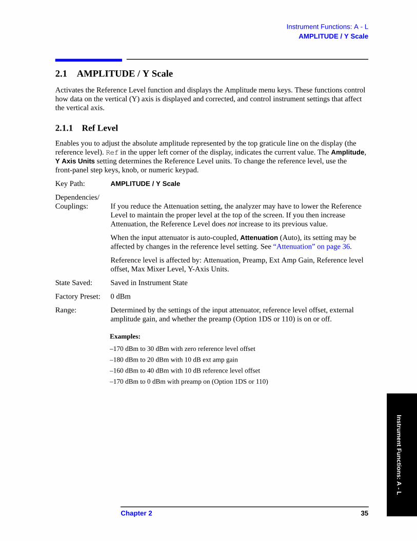
Instrument Functions: A - LAMPLITUDE / Y Scale
Instrument Functions: A
- L
2.1 AMPLITUDE / Y Scale
Activates the Reference Level function and displays the Amplitude menu keys. These functions control how data on the vertical (Y) axis is displayed and corrected, and control instrument settings that affect the vertical axis.
2.1.1 Ref Level
Enables you to adjust the absolute amplitude represented by the top graticule line on the display (the reference level). Ref in the upper left corner of the display, indicates the current value. The Amplitude, Y Axis Units setting determines the Reference Level units. To change the reference level, use the front-panel step keys, knob, or numeric keypad.
Key Path: AMPLITUDE / Y Scale
Dependencies/ Couplings: If you reduce the Attenuation setting, the analyzer may have to lower the Reference
Level to maintain the proper level at the top of the screen. If you then increase Attenuation, the Reference Level does not increase to its previous value.
When the input attenuator is auto-coupled, Attenuation (Auto), its setting may be affected by changes in the reference level setting. See “Attenuation” on page 36.
Reference level is affected by: Attenuation, Preamp, Ext Amp Gain, Reference level offset, Max Mixer Level, Y-Axis Units.
State Saved: Saved in Instrument State
Factory Preset: 0 dBm
Range: Determined by the settings of the input attenuator, reference level offset, external amplitude gain, and whether the preamp (Option 1DS or 110) is on or off.
Examples:
–170 dBm to 30 dBm with zero reference level offset–180 dBm to 20 dBm with 10 dB ext amp gain–160 dBm to 40 dBm with 10 dB reference level offset–170 dBm to 0 dBm with preamp on (Option 1DS or 110)
Chapter 2 35
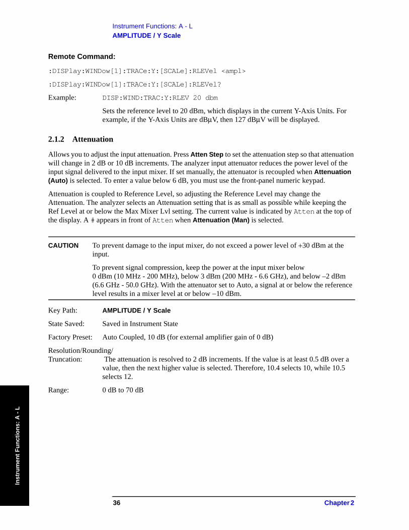
Instrument Functions: A - LAMPLITUDE / Y Scale
Inst
rum
ent F
unct
ions
: A -
L
Remote Command:
:DISPlay:WINDow[1]:TRACe:Y:[SCALe]:RLEVel <ampl>
:DISPlay:WINDow[1]:TRACe:Y:[SCALe]:RLEVel?
Example: DISP:WIND:TRAC:Y:RLEV 20 dbm
Sets the reference level to 20 dBm, which displays in the current Y-Axis Units. For example, if the Y-Axis Units are dBμV, then 127 dBμV will be displayed.
2.1.2 Attenuation
Allows you to adjust the input attenuation. Press Atten Step to set the attenuation step so that attenuation will change in 2 dB or 10 dB increments. The analyzer input attenuator reduces the power level of the input signal delivered to the input mixer. If set manually, the attenuator is recoupled when Attenuation (Auto) is selected. To enter a value below 6 dB, you must use the front-panel numeric keypad.
Attenuation is coupled to Reference Level, so adjusting the Reference Level may change the Attenuation. The analyzer selects an Attenuation setting that is as small as possible while keeping the Ref Level at or below the Max Mixer Lvl setting. The current value is indicated by Atten at the top of the display. A # appears in front of Atten when Attenuation (Man) is selected.
CAUTION To prevent damage to the input mixer, do not exceed a power level of +30 dBm at the input.
To prevent signal compression, keep the power at the input mixer below 0 dBm (10 MHz - 200 MHz), below 3 dBm (200 MHz - 6.6 GHz), and below –2 dBm (6.6 GHz - 50.0 GHz). With the attenuator set to Auto, a signal at or below the reference level results in a mixer level at or below −10 dBm.
Key Path: AMPLITUDE / Y Scale
State Saved: Saved in Instrument State
Factory Preset: Auto Coupled, 10 dB (for external amplifier gain of 0 dB)
Resolution/Rounding/ Truncation: The attenuation is resolved to 2 dB increments. If the value is at least 0.5 dB over a
value, then the next higher value is selected. Therefore, 10.4 selects 10, while 10.5 selects 12.
Range: 0 dB to 70 dB
36 Chapter 2

Instrument Functions: A - LAMPLITUDE / Y Scale
Instrument Functions: A
- L
Remote Command:
[:SENSe]:POWer[:RF]:ATTenuation <rel_power>
[:SENSe]:POWer[:RF]:ATTenuation?
[:SENSe]:POWer[:RF]:ATTenuation:AUTO OFF|ON|0|1
[:SENSe]:POWer[:RF]:ATTenuation:AUTO?
Remote Command Notes: The Reference Level setting may be affected when the Attenuation is changed. See“Ref Level” on page 35.
Example: POW:ATT 30
POW:ATT?
POW:ATT:AUTO ON
POW:ATT:AUTO?
2.1.3 Scale/Div
Sets the units per vertical graticule division on the display. This function is only available when Scale Type (Log) is selected and the vertical scale is power, or Demod View is on and the vertical scale is hertz. When Scale Type (Lin) is selected, Scale/Div is unavailable.
Key Path: AMPLITUDE / Y Scale
State Saved: Saved in Instrument State
Factory Preset: 10 dB, in logarithmic scale type
Fundamental Units: dB; kHz
Terminators: dB; Hz, kHz, MHz, GHz
Default Terminator: dB; kHz
Range: 0.1 dB to 20 dB
1 kHz to 240 kHz (When Demod View (On) is selected.)
Remote Command:
:DISPlay:WINDow[1]:TRACe:Y:[SCALe]:PDIVision <power>
:DISPlay:WINDow[1]:TRACe:Y:[SCALe]:PDIVision?
Example: DISP:WIND:TRAC:Y:PDIV 5 DB
Chapter 2 37
Instrument Functions: A - LAMPLITUDE / Y Scale
Inst
rum
ent F
unct
ions
: A -
L
2.1.4 Scale Type
Allows you to choose a linear or logarithmic vertical scale for the display and for remote data readout.
The scale type for display and remote data readout may be different from the scale used for averaging processes. For information on the scale used for the averaging process, see “Avg/VBW Type” on page 72.
When Scale Type (Log) is selected, the vertical graticule divisions are scaled in logarithmic units. The top line of the graticule is the Reference Level and uses the scaling per division, Scale/Div to assign values to the other locations on the graticule.
When Scale Type (Lin) is selected, the vertical graticule divisions are linearly scaled with the reference level value at the top of the display and zero volts at the bottom. Each vertical division of the graticule represents one-tenth of the Reference Level.
The Y-axis units used for each type of display are set by pressing Y Axis Units. The analyzer remembers the settings for both Log and Lin.
Key Path: AMPLITUDE / Y Scale
State Saved: Saved in Instrument State
Factory Preset: Log
Remote Command:
:DISPlay:WINDow[1]:TRACe:Y:[SCALe]:SPACing LINear|LOGarithmic
:DISPlay:WINDow[1]:TRACe:Y:[SCALe]:SPACing?
Example: DISP:WIND:TRAC:Y:SPAC LOG
DISP:WIND:TRAC:Y:SPAC?
2.1.5 Presel Center
Adjusts the centering of the preselector filter to optimize the amplitude accuracy at the frequency of the active marker. If no marker is on when Presel Center is pressed, the analyzer turns on the currently selected marker and does a peak search. If a marker is already on, it should be placed on the peak of interest before pressing Presel Center.
Some models of the analyzer contain more than one preselector. The microwave preselector is used for frequencies from 2.85 or 3.05 GHz (depending on frequency band) to 26.8 GHz. The millimeter preselector is used for frequencies from 26.5 GHz to the maximum frequency of the analyzer (the millimeter preselector is only available in analyzers with a frequency range greater than 26.5 GHz). To center both preselectors, the user must set up and request a Presel Center in a microwave band, then set up and request a Presel Center in a millimeter band. (See Presel Adjust for more details.).
The unpreselected high-band Option 123 lets you bypass the preselector path. (See Input/Output, Microwave Preselector and Input/output, μW/mmW Preselectors.)
When the preselector path is bypassed, the Presel Center and Presel Adjust keys are unavailable (unless you are using external mixing with preselected external mixers.)
For proper preselector centering, you should make sure that:
38 Chapter 2
Instrument Functions: A - LAMPLITUDE / Y Scale
Instrument Functions: A
- L
• If the marker is off, the highest peak onscreen is valid for centering and is in the range of an active preselector
or
• If the marker is on, the signal at the marker is a peak that allows centering and is in the range of an active preselector.
Other considerations or cautions include:
• If a marker is already on, the analyzer attempts the centering at the current marker position and no peak search is performed. (This allows the user to center the preselector for signals which are not the strongest on-screen signals.)
• The preselector path can be bypassed. See Input/Output, Microwave Preselector and Input/output, μW/mmW Preselectors. If it is bypassed, this functionality is not available.
• If the signal at the marker position is unstable the algorithm will not function properly. An example of this would be noise or a noise-like signal like a CDMA digital communications signal.
• There is no preselector for signals below 3.05 GHz (in band 0).
• With Input Mixer (Ext) selected and the Mixer Type set to Presel (preselected), Presel Center adjusts the frequency of the external preselector filter to maximize the amplitude at the active marker frequency.
Key Path: AMPLITUDE / Y Scale
Dependencies/ Couplings: This function is not available (grayed out) if:
• the preselector is off. (See Input/Output, Microwave Preselector and Input/output, μW/mmW Preselectors.)
• external mixing is selected and Mixer Type is unpreselected.
• the frequency range is entirely within band 0 (0 Hz to ~3.05 GHz).
• the gated sweep function is on (Sweep, Gate on.)
History: Modified in revision A.09.00.
Remote Command:
[:SENSe]:POWer[:RF]:PCENter
Remote Command Notes: If this command is sent in a non-preselected band, or if the active marker is less than 3 GHz, an error message is sent.
Example: POW:PCEN
Chapter 2 39
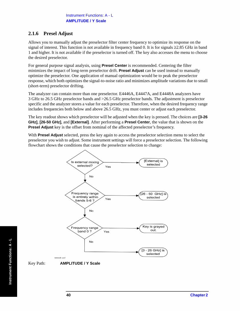
Instrument Functions: A - LAMPLITUDE / Y Scale
Inst
rum
ent F
unct
ions
: A -
L
2.1.6 Presel Adjust
Allows you to manually adjust the preselector filter center frequency to optimize its response on the signal of interest. This function is not available in frequency band 0. It is for signals ≥2.85 GHz in band 1 and higher. It is not available if the preselector is turned off. The key also accesses the menu to choose the desired preselector.
For general purpose signal analysis, using Presel Center is recommended. Centering the filter minimizes the impact of long-term preselector drift. Presel Adjust can be used instead to manually optimize the preselector. One application of manual optimization would be to peak the preselector response, which both optimizes the signal-to-noise ratio and minimizes amplitude variations due to small (short-term) preselector drifting.
The analyzer can contain more than one preselector. E4446A, E4447A, and E4448A analyzers have 3 GHz to 26.5 GHz preselector bands and >26.5 GHz preselector bands. The adjustment is preselector specific and the analyzer stores a value for each preselector. Therefore, when the desired frequency range includes frequencies both below and above 26.5 GHz, you must center or adjust each preselector.
The key readout shows which preselector will be adjusted when the key is pressed. The choices are [3-26 GHz], [26-50 GHz], and [External]. After performing a Presel Center, the value that is shown on the Presel Adjust key is the offset from nominal of the affected preselector’s frequency.
With Presel Adjust selected, press the key again to access the preselector selection menu to select the preselector you wish to adjust. Some instrument settings will force a preselector selection. The following flowchart shows the conditions that cause the preselector selection to change:
Key Path: AMPLITUDE / Y Scale
40 Chapter 2
Instrument Functions: A - LAMPLITUDE / Y Scale
Instrument Functions: A
- L
Dependencies/ Couplings: This function is not available (grayed out) if:
• the preselector is off. (See Input/Output, Microwave Preselector and Input/output, μW/mmW Preselectors.)
• external mixing is selected and Mixer Type is unpreselected.
• the frequency range is entirely within band 0 (0 Hz to ~3.05 GHz).
• the gated sweep function is on (Sweep, Gate on.)
State Saved: Saved in Instrument State
Factory Preset: 3 - 26 GHz, 0.0 Hz
Range: –500 MHz to 500 MHz
History: Modified in revision A.09.00.
Remote Command:
[:SENSe]:POWer[:RF]:PADJust <freq>
[:SENSe]:POWer[:RF]:PADJust?
[:SENSe]:POWer[:RF]:PADJust:PRESelector MWAVe|MMWave|EXTernal
[:SENSe]:POWer[:RF]:PADJust:PRESelector?
Example: POW:PADJ:PRES MMW
POW:PADJ 100 KHZ
2.1.7 3 - 26 GHz
Selects the preselector for the analyzers microwave frequency bands.
Key Path: AMPLITUDE / Y Scale, Presel Adjust
Dependencies/ Couplings: This function is not available (grayed out) if:
• the microwave preselector is bypassed (see Input/Output, Microwave Preselector and Input/output, μW/mmW Preselectors.) Error 229 is sent.
• external mixing is selected. Error 231 is sent.
• the span is entirely in band 0. Error 208 is sent.
• the span is entirely in bands 5-6. Error 208 is sent.
History: Modified in revision A.09.00.
Remote Command:
See “Presel Adjust” on page 40.
Chapter 2 41

Instrument Functions: A - LAMPLITUDE / Y Scale
Inst
rum
ent F
unct
ions
: A -
L
2.1.7.1 26 - 50 GHz
Selects the preselector for the analyzer’s millimeterwave frequency bands.
Key Path: AMPLITUDE / Y Scale, Presel Adjust
Dependencies/ Couplings: This function is not available (grayed out) if:
• the millimeter wave preselector is bypassed (see Input/output, μW/mmW Preselectors.) Error 229 is sent.
• no part of the span is in bands 5 or 6. Error 208 is sent.• using external mixing. Error 231 is sent.
History: Modified in revision A.09.00.
Remote Command:
See “Presel Adjust” on page 40.
2.1.7.2 External
Selects the external mixer preselector.
Key Path: AMPLITUDE / Y Scale, Presel Adjust
Dependencies/ Couplings: • It is only available if Option AYZ is installed.
• It is unavailable if external mixing is off. Error 232 is sent.• It is unavailable if you are using external mixing and have specified an
unpreselected external mixer. Error 230 is sent.
History: Added in revision A.06.00.
Remote Command:
See “Presel Adjust” on page 40.
2.1.8 Y Axis Units
Displays the menu keys that enable you to change the vertical (Y) axis amplitude units. The analyzer retains the entered Y Axis Units separately for both Log and Lin amplitude scale types. For example, if Scale Type has been set to Log, and you set Y Axis Units to dBm, pressing Scale Type (Log) sets the Y Axis Units to dBm. If Scale Type has been set to Lin and you set Y Axis Units to Volts, pressing Scale Type (Lin) sets the Y Axis Units to Volts. Pressing Scale Type (Log) again sets the Y Axis Units back to dBm.
This key is unavailable (grayed out) when the FM Demod View is on.
Y Axis Units, in conjunction with the Scale Type, affect how the data is read off the display, markers, and over the remote interface. When using the remote interface no units are returned, so you must know what the Y-Axis units are to interpret the results.
Key Path: AMPLITUDE / Y Scale
State Saved: Saved in Instrument State
42 Chapter 2

Instrument Functions: A - LAMPLITUDE / Y Scale
Instrument Functions: A
- L
Factory Preset: For Scale Type (Log) = dBm
For Scale Type (Lin) = Volts
Remote Command:
:UNIT:POWer DBM|DBMV|DBMA|V|W|A|DBUV|DBUA|DBUVM|DBUAM|DBPT|DBG
:UNIT:POWer?
Remote Command Notes: The settings of Y Axis Units and Scale Type, affect how the data is read over the
remote interface. When using the remote interface no units are returned, so you must know what the Y-Axis units are to interpret the results:
Example 1, set the following:
Scale Type (Log) Y Axis Units, dBm Scale/Div, 1 dB Ref Level, 10 dBm
This sets the top line to 10 dBm with each vertical division representing 1 dB. Thus, if a point on trace 1 is on the fifth graticule line from the top, it represents 5 dBm and will read out remotely as 5.
Example 2, set the following:
Scale Type (Lin)Y Axis Units, VoltsRef Level, 100 mV (10 mV/div)
This sets the top line to 100 mV and the bottom line to 0 V, so each vertical division represents 10 mV. Thus, if a point on trace 1 is on the fifth graticule line from the top, it represents 50 mV and will read out remotely as 50.
Example: UNIT:POW dBmV
UNIT:POW?
2.1.8.1 dBm
Sets the amplitude units to dBm.
Key Path: AMPLITUDE / Y Scale, More, Y Axis Units
Remote Command:
See “Y Axis Units” on page 42.
Example: UNIT:POW DBM
2.1.8.2 dBmV
Sets the amplitude units to dBmV.
Key Path: AMPLITUDE / Y Scale, More, Y Axis Units
Chapter 2 43
Instrument Functions: A - LAMPLITUDE / Y Scale
Inst
rum
ent F
unct
ions
: A -
L
Remote Command:
See “Y Axis Units” on page 42.
Example: UNIT:POW DBMV
2.1.8.3 dBmA
Sets the amplitude units to dBmA.
Key Path: AMPLITUDE / Y Scale, More, Y Axis Units
Remote Command:
See “Y Axis Units” on page 42.
Example: UNIT:POW DBMA
2.1.8.4 Volts
Sets the amplitude units to volts.
Key Path: AMPLITUDE / Y Scale, More, Y Axis Units
Remote Command:
See “Y Axis Units” on page 42.
Example: UNIT:POW V
2.1.8.5 Watts
Sets the amplitude units to watts.
Key Path: AMPLITUDE / Y Scale, More, Y Axis Units
Remote Command:
See “Y Axis Units” on page 42.
Example: UNIT:POW W
2.1.8.6 Amps
Sets the amplitude units to amps.
Key Path: AMPLITUDE / Y Scale, More, Y Axis Units
History: Added with firmware revision A.06.00
Remote Command:
See “Y Axis Units” on page 42.
Example: UNIT:POW A
44 Chapter 2
Instrument Functions: A - LAMPLITUDE / Y Scale
Instrument Functions: A
- L
2.1.8.7 dBμV
Sets the amplitude units to dBμV.
Key Path: AMPLITUDE / Y Scale, More, Y Axis Units
Remote Command:
See “Y Axis Units” on page 42.
Example: UNIT:POW DBUV
2.1.8.8 dBμA
Sets the amplitude units to dBμA.
Key Path: AMPLITUDE / Y Scale, More, Y Axis Units
History: Added with firmware revision A.06.00
Remote Command:
See “Y Axis Units” on page 42.
Example: UNIT:POW DBUA
2.1.8.9 dBμV/m
Sets the amplitude units to dBμV/m. This is a unit specifically applicable to EMI field strength measurements. In the absence of a correction factor this unit is treated by the instrument exactly as though it were dBμV. You must load an appropriate correction factor using amplitude corrections for this unit to generate meaningful results. Therefore, this key is unavailable unless one of the corrections is turned on (in Amplitude, Corrections menu) and Apply Corrections is set to Yes.
Key Path: AMPLITUDE / Y Scale, More, Y Axis Units
Dependencies/ Couplings: If the grayed out key is pressed, an error message is generated.
History: Added with firmware revision A.06.00
Remote Command:
See “Y Axis Units” on page 42.
Example: UNIT:POW DBUVM
2.1.8.10 dBμA/m
Sets the amplitude units to dBμA/m. This is a unit specifically applicable to EMI field strength measurements. In the absence of a correction factor this unit is treated by the instrument exactly as though it were dBμV. You must load an appropriate correction factor using amplitude corrections for this unit to generate meaningful results. Therefore, this key is unavailable unless one of the corrections is turned on (in Amplitude, Corrections menu) and Apply Corrections is set to Yes.
Key Path: AMPLITUDE / Y Scale, More, Y Axis Units
Chapter 2 45
Instrument Functions: A - LAMPLITUDE / Y Scale
Inst
rum
ent F
unct
ions
: A -
L
Dependencies/ Couplings: If the grayed out key is pressed, an error message is generated.
History: Added with firmware revision A.06.00
Remote Command:
See “Y Axis Units” on page 42.
Example: UNIT:POW DBUAM
2.1.8.11 dBpT
Sets the amplitude units to dBpT. This is a unit specifically applicable to EMI field strength measurements. In the absence of a correction factor this unit is treated by the instrument exactly as though it were dBμV. You must load an appropriate correction factor using amplitude corrections for this unit to generate meaningful results. Therefore, this key is unavailable unless one of the corrections is turned on (in Amplitude, Corrections menu) and Apply Corrections is set to Yes.
Key Path: AMPLITUDE / Y Scale, More, Y Axis Units
Dependencies/ Couplings: If the grayed out key is pressed, an error message is generated.
History: Added with firmware revision A.06.00
Remote Command:
See “Y Axis Units” on page 42.
Example: UNIT:POW DBPT
2.1.8.12 dBG
Sets the amplitude units to dBG. This is a unit specifically applicable to EMI field strength measurements. In the absence of a correction factor this unit is treated by the instrument exactly as though it were dBμV. You must load an appropriate correction factor using amplitude corrections for this unit to generate meaningful results. Therefore, this key is unavailable unless one of the corrections is turned on (in Amplitude, Corrections menu) and Apply Corrections is set to Yes.
Key Path: AMPLITUDE / Y Scale, More, Y Axis Units
Dependencies/ Couplings: If the grayed out key is pressed, an error message is generated.
History: Added with firmware revision A.06.00
Remote Command:
See “Y Axis Units” on page 42.
Example: UNIT:POW DBG
2.1.9 Ref Lvl Offset
Allows you to add an offset value to the displayed reference level. The reference level is the absolute
46 Chapter 2

Instrument Functions: A - LAMPLITUDE / Y Scale
Instrument Functions: A
- L
amplitude represented by the top graticule line on the display. Reference-level offsets are entered by using the numeric keypad or programming commands. The knob and step keys are not active.
Offsets are used when a gain or loss occurs between a device under test and the analyzer input. Thus, the signal level measured by the analyzer may be thought of as the level at the input of an external amplitude conversion device. Entering an offset does not affect the trace position or attenuation value, just the displayed value readouts such as reference level and marker amplitudes.
The maximum reference level available is dependent on the reference level offset. That is, Ref Level − Ref Level Offset must be in the range −170 to +30 dBm.
For example, the reference level value range can be initially set to values from −170 dBm to 30 dBm with no reference level offset. If the reference level is first set to −20 dBm, then the reference level offset can be set to values of −50 to +150 dB.
If the reference level offset is first set to −30 dB, then the reference level can be set to values of −200 dBm to 0 dBm. In this case, the reference level is “clamped” at 0 dBm because the maximum limit of +30 dBm is reached with a reference level setting of 0 dBm with an offset of −30 dB. If instead, the reference level offset is first set to 30 dB, then the reference level can be set to values of −140 to +60 dBm.
When a reference level offset is entered, the offset value appears on the left side of the display under Offst (as opposed to frequency offsets which appear at the bottom of the display.) To eliminate an offset, press Ref Lvl Offst, 0, and dB.
Key Path: AMPLITUDE / Y Scale
Key Notes: Only numeric entries are valid, the knob and step keys are not applicable to this function.
Annunciation/ Annotation: The offset is displayed to the left of the Trace window; third from the top, just below
the scale type.
State Saved: Saved in Instrument State
Factory Preset: 0.0 dB
Range: –327.6 dB to 327.6 dB
Remote Command:
:DISPlay:WINDow[1]:TRACe:Y:[SCALe]:RLEVel:OFFSet <rel_power> (in dB)
:DISPlay:WINDow[1]:TRACe:Y:[SCALe]:RLEVel:OFFSet?
Example: DISP:WIND:TRAC:Y:RLEV:OFFS 12.7
Sets the Ref Level Offset to 12.7 dB. The only valid suffix is dB. If no suffix is sent, dB will be assumed.
2.1.10 Int Preamp
(Options 1DS and 110 only.) Turns the internal preamp on and off. Option 1DS preamp functions over a frequency range of 100 kHz to 3 GHz. Option 110 preamp functions over a frequency range of 100 kHz to 50 GHz. When the preamp is on, an automatic adjustment compensates for the gain of the preamp so
Chapter 2 47

Instrument Functions: A - LAMPLITUDE / Y Scale
Inst
rum
ent F
unct
ions
: A -
L
that the displayed amplitude readings still accurately reflect the value at the analyzer input connector. The Option 1DS preamp is switched off for frequencies above 3 GHz, and the correction is not applied, even though the PA annotation remains on screen. For signal frequencies below 100 kHz, the preamp is not automatically switched out, but signal amplitude roll-off occurs even in the “DC” setting of the RF Coupling control.
The gain of the preamp is nominally 30 dB. This functionality is not available when using external mixing.
Key Path: AMPLITUDE / Y Scale
Dependencies/ Couplings: Reference level, Attenuation
State Saved: Saved in Instrument State
Factory Preset: Off
Remote Command:
[:SENSe]:POWer[:RF]:GAIN[:STATe] OFF|ON|0|1
[:SENSe]:POWer[:RF]:GAIN[:STATe]?
Example: POW:GAIN 1
POW:GAIN?
2.1.11 Corrections
Accesses the Corrections menu keys that allow you to enable the corrections function and to select which set of correction factors you wish to modify. These frequency and amplitude corrections will be applied to the displayed data to correct for system losses or gains outside the analyzer. Four different sets of correction data can be stored.
Key Path: AMPLITUDE / Y Scale, More
Remote Command:
There is no equivalent remote command for this key.
2.1.11.1 Apply Corrections
Pressing Apply Corrections (Yes) turns on the amplitude-correction factors. Corrections will only be applied for the sets of correction factors whose correction state is set to On. To turn a set of correction factors on, use the Correction On Off key in the Antenna, Cable, Other, or User menus.
Key Path: AMPLITUDE / Y Scale, More, Corrections
Annunciation/ Annotation: When Apply Corrections (Yes) is selected, an A will appear in the screen annotation
on the left edge of the display, whether or not a correction set has been turned on using the Correction (On) key in the Antenna, Cable, Other, or User menus.
State Saved: Saved in Instrument State
Factory Preset: No
48 Chapter 2
Instrument Functions: A - LAMPLITUDE / Y Scale
Instrument Functions: A
- L
Remote Command:
[:SENSe]:CORRection:CSET:ALL[:STATe] OFF|ON|0|1
[:SENSe]:CORRection:CSET:ALL[:STATe]?
Remote Command Notes: To turn On or Off an individual correction set, use: [:SENSe]:CORRection:CSET[1]|2|3|4[:STATe]
Example: CORR:CSET:ALL ON
CORR:CSET:ALL?
2.1.11.2 Antenna, Cable, Other, and User Keys
Pressing Antenna, Cable, Other, or User accesses the Correction menu for that type of correction data. These 4 keys display the status of correction sets. If the key indicates On, then amplitude corrections for this type have been enabled. To perform the corrections, both this key and Apply Corrections must indicate Yes. The status is toggled in the correction set menu located under Correction.
Key Path: AMPLITUDE / Y Scale, More, Corrections
Remote Command:
There is no remote command for this key.
2.1.11.2.1 Correction
Turns the amplitude correction function on or off for the specific set of correction data. The corrections state must be set to On for the correction to be applied.
NOTE Antenna, Cable, and Other correction factors are generally entered as positive values. This indicates a loss in the external device. User correction factors are typically entered as negative values which indicate a gain in the external device.
Key Path: AMPLITUDE / Y Scale, More, Corrections, Antenna (Cable, Other, or User)
State Saved: Saved in Instrument State
Factory Preset: No
Remote Command:
[:SENSe]:CORRection:CSET[1]|2|3|4[:STATe] OFF|ON|0|1
[:SENSe]:CORRection:CSET[1]|2|3|4[:STATe]?
Remote Command Notes: [:SENSe]:CORRection:CSET:ALL[:STATe] must be set to on for this command
to function.
CSET number equivalents to front-panel access definitions are as follows:
CSET or CSET1 is AntennaCSET2 is CableCSET3 is Other
Chapter 2 49
Instrument Functions: A - LAMPLITUDE / Y Scale
Inst
rum
ent F
unct
ions
: A -
L
CSET4 is User
Example: CORR:CSET2 ON
CORR:CSET2?
2.1.11.2.2 Edit
Accesses menu keys that allow you to create and edit an amplitude-correction factor set. It puts the analyzer into a split-screen mode where the correction data is displayed in a table under the trace data. Pressing ESC while in this menu will exit the menu and remove the table from the screen. New points will be applied only after the editor is closed.
Key Path: AMPLITUDE / Y Scale, More, Corrections, Antenna (Cable, Other, or User)
Remote Command:
[:SENSe]:CORRection:CSET[1]|2|3|4:DATA <freq>,<rel_ampl>{,<freq>,<rel_ampl>} Creates an amplitude-correction factor set
[:SENSe]:CORRection:CSET[1]|2|3|4:DATA:MERGe <freq>,<rel_ampl>{,<freq>,<rel_ampl>} Adds the points with the specified values to the current amplitude correction data, allowing you to merge correction data. If too much data is merged, as many points as possible are merged into the existing data and then an error is reported.
[:SENSe]:CORRection:CSET[1]|2|3|4:DATA?
Remote Command Notes: [:SENSe]:CORRection:CSET:ALL[:STATe] must be set to on for this command to function.
CSET number equivalents to front-panel access definitions are as follows:
CSET or CSET1 is AntennaCSET2 is CableCSET3 is OtherCSET4 is User
• <freq> is the frequency (in Hz) where the correction should be applied; no unit is allowed in this parameter
• <rel_ampl> is the amount of relative amplitude correction (in dB) needed; no unit is allowed in this parameter
Example: :CORR:CSET2:DATA 900E6,0.3,1.0E9,0.35,1.3E9,0.2
2.1.11.2.2.1 Point
Allows you to create or edit an amplitude-correction factor data point. Up to 200 points may be defined for each set. Enter the point number to be created or edited by using the numeric keypad, then press Enter, or use the knob or step keys to move to an existing point. After selecting a point, Frequency becomes active.
Key Path: AMPLITUDE / Y Scale, More, Corrections, Antenna (Cable, Other, or User), Edit
State Saved: Not part of instrument state, saved in a corrections file.
50 Chapter 2
Instrument Functions: A - LAMPLITUDE / Y Scale
Instrument Functions: A
- L
Remote Command:
See “Edit” on page 50.
2.1.11.2.2.2 Frequency
A frequency coordinate must always be specified for amplitude-correction factors. Amplitude-correction data is sorted in the table by frequency. The sorting occurs immediately after you have entered the frequency value through the front-panel.
Allows you to enter the frequency value for an amplitude-correction point. Enter the frequency value by using the numeric keypad. Change the frequency value by using the step keys or the knob. After entering a frequency, Amplitude becomes active.
NOTE The amplitude correction entered for the lowest frequency will be applied to all frequencies less than the lowest frequency entered. Similarly, the amplitude correction for the highest frequency entered will be applied to all frequencies greater than the highest frequency entered.
Key Path: AMPLITUDE / Y Scale, More, Corrections, Antenna (Cable, Other, or User), Edit
State Saved: Not part of instrument state, saved in a corrections file.
Remote Command:
See “Edit” on page 50.
2.1.11.2.2.3 Amplitude
Allows you to enter the amplitude value for the current amplitude-correction point. After entering an amplitude, the point number automatically increments and Frequency becomes active to allow entry of the frequency of the next point.
Key Path: AMPLITUDE / Y Scale, More, Corrections, Antenna (Cable, Other, or User), Edit
State Saved: Not part of instrument state, saved in a corrections file.
Remote Command:
See “Edit” on page 50.
2.1.11.2.2.4 Delete Point
Allows you to delete the amplitude-correction data for the currently selected point. The prompt “If you are sure, press key again to delete” will appear on the display. Pressing Delete Point again will delete the point and adjust all of the point numbers as appropriate.
Key Path: AMPLITUDE / Y Scale, More, Corrections, Antenna (Cable, Other, or User), Edit
Remote Command:
See “Edit” on page 50.
2.1.11.2.3 Delete Corrections
Allows you to clear all data from the selected amplitude-correction set. The prompt “If you are sure, press key again to delete” will appear on the display. Pressing Delete again will delete
Chapter 2 51

Instrument Functions: A - LAMPLITUDE / Y Scale
Inst
rum
ent F
unct
ions
: A -
L
the correction set.
Key Path: AMPLITUDE / Y Scale, More, Corrections, Antenna (Cable, Other, or User)
Remote Command:
[:SENSe]:CORRection:CSET[1]|2|3|4:DELete
Remote Command Notes: CSET number equivalents to front-panel access definitions are as follows:
CSET or CSET1 is AntennaCSET2 is CableCSET3 is OtherCSET4 is User
Example: CORR:CSET4:DEL
2.1.11.3 Freq Interp
Allows you to determine how trace values are computed between points in a correction table. If the linear mode is selected, a straight line is used between points in the correction table (for a linear frequency scale and for a decibel amplitude scale). If the logarithmic mode is selected, frequency values between points are computed by first taking the logarithm of both table values and the intermediate value, while using decibel amplitude values.
Key Path: AMPLITUDE / Y Scale, More, Corrections
State Saved: Not saved in instrument state
Factory Preset: Not affected by Factory Preset. Will be set to linear by Restore Factory Defaults.
Remote Command:
[:SENSe]:CORRection:CSET[1]|2|3|4:X:SPACing LINear|LOGarithmic
Example: CORR:CSET4:X:SPAC LOG
2.1.11.4 Delete All Corrections
Allows you to delete all amplitude-correction sets.
Key Path: AMPLITUDE / Y Scale, More, Corrections
Dependencies/ Couplings: If corrections are on, corrections are turned off.
Remote Command:
[:SENSe]:CORRection:CSET:ALL:DELete
Example: CORR:CSET:ALL:DEL
2.1.12 Ext Amp Gain
Compensates for external gain or loss. The function is similar to the Ref Lvl Offset function, however
52 Chapter 2
Instrument Functions: A - LAMPLITUDE / Y Scale
Instrument Functions: A
- L
this value is considered, along with the maximum mixer level setting, to determine the attenuation required (10 dB of Attenuation is added for every 10 dB of External Amp Gain). The gain is subtracted from the amplitude readout so that the displayed signal level represents the signal level at the input of the external device.
Gains may only be entered with the numeric keypad or programming commands, not the knob or step keys.
Key Path: AMPLITUDE / Y Scale
State Saved: Saved in Instrument State, and survives a Preset and power cycle.
Factory Default: 0 dB
Range: –81.90 dB to 81.90 dB
NOTE Ext Amp Gain is not affected by a Factory Preset or power cycle. It can be reset to the factory default by pressing System, Restore Sys Defaults.
Remote Command:
[:SENSe]:CORRection:OFFSet[:MAGNitude] <relative_power> (in dB)
[:SENSe]:CORRection:OFFSet[:MAGNitude]?
Example: CORR:OFFS:MAGN 7.3 DB
Sets the Ext Amp Gain to 7.3 dB. The only valid suffix is dB. If no suffix is sent, dB is assumed.
2.1.13 Atten Step
Enables you to select 2 dB or 10 dB step resolution for input attenuation.
Key Path: AMPLITUDE / Y Scale
Saved State: Saved in Instrument State
Factory Preset: 2 dB
Remote Command:
[:SENSe]:POWer[:RF]:ATTenuation:STEP[:INCRement] <integer> (in dB)
[:SENSe]:POWer[:RF]:ATTenuation:STEP[:INCRement]?
Example: POW:ATT:STEP 10
Sets the Attenuation to 10 dB. The only valid suffix is dB. If no suffix is sent, dB is assumed.
If a value >5 is entered, 10 is used.
If a value ≤ 5 is entered, 2 is used
Chapter 2 53
Instrument Functions: A - LAMPLITUDE / Y Scale
Inst
rum
ent F
unct
ions
: A -
L
2.1.14 Max Mixer Lvl
Enables you to set the relationship between the highest signal that can be displayed (the reference level) and the input attenuation. The relationship applies whenever the Attenuation is set to Auto. The relationship is that the attenuation is given by the reference level minus the max mixer level. For example, as the reference level changes, the input attenuator changes to ensure that a signal at the reference level does not exceed the Max Mixer Lvl setting.
Key Path: AMPLITUDE / Y Scale
State Saved: Saved in Instrument State
Factory Preset: –10 dBm
Range: –50 dBm to –10 dBm (internal mixing)
–50 dBm to +10 dBm (external mixing)
Remote Command:
[:SENSe]:POWer[:RF]:MIXer:RANGe[:UPPer] <power>
[:SENSe]:POWer[:RF]:MIXer:RANGe[:UPPer]?
Example: POW:MIX:RANG -15 dBm
54 Chapter 2
Instrument Functions: A - LAuto Couple
Instrument Functions: A
- L
2.2 Auto Couple Coupled functions are functions that are linked to or dependent on other functions. Pressing Auto Couple displays some of the most important coupled analyzer functions.
An example of a coupled function is Res BW (resolution bandwidth). When Res BW is set to auto, the Res BW is automatically set based on the span setting.
Coupled functions are affected depending on how they are coupled. For example, Video BW is coupled to Res BW, so changing Res BW affects Video BW, but changing Video BW does not affect Res BW. Changing Video BW puts it in manual (instead of auto-coupled). When Video BW is set to Man it is unaffected by Res BW changes.
When a function is in the Man state, a # will appear next to its annotation on the display. If one or more functions are manually set so that the amplitude or frequency measurement becomes uncalibrated, “Meas Uncal” appears on the top right side of the graticule.
2.2.1 Auto All
Auto-couples all coupled functions. If Auto All is pressed, all coupled functions are set to Auto. Setting any auto coupled function to Man (manual), uncouples that function without changing the coupling of other functions.
Coupled functions are functions that are linked. When Auto All is pressed, the analyzer automatically couples all instrument settings that have auto and manual choices. In most cases, these auto settings give the most accurate measurements and optimum dynamic range. When a function is coupled, it is in the Auto state. When it is uncoupled it is in the Man state.
Key Path: Auto Couple
Dependencies/ Couplings: When Auto All is selected:
• Resolution BW couples to: Span and Span/RBW• Video BW couples to: Res BW and VBW/RBW• Sweep Time couples to: Res BW; Video BW; Detector; Span and Center
Frequency• CF Step couples to: Span in swept spans, to Res BW in zero span• Attenuation couples to: Ref Level; Ext Amp Gain; Atten Step; Max Mixer Lvl;
and Int Preamp• FFT & Sweep couples to: Res BW and Span• PhNoise Opt (phase noise optimization) couples to: Res BW; Span and FFT &
Sweep sweep type• Detector couples to: marker functions; Avg/VBW Type; Average On Off; Max
Hold and Min Hold• Average Type couples to: the marker functions; Detector and Scale Type• ADC Dither couples to: Sweep Type; Span; Res BW; ADC Ranging and
FFTs/Span• VBW/RBW ratio is set to 1.0• Span/RBW ratio is set to Auto
Chapter 2 55
Instrument Functions: A - LAuto Couple
Inst
rum
ent F
unct
ions
: A -
L
• Auto Sweep Time is set to Normal• FFT & Sweep is set to Auto:Best Dynamic Range• ADC Ranging is set to Autorange• Marker Count, Gate Time is set to Auto
NOTE Marker Trace and Printer have an Auto setting, but are not affected by Auto All.
Remote Command:
:COUPle ALL|NONE
:COUPle?
Remote Command Notes: COUPle NONE sets all the functions to the manual (not coupled) mode. There is no front-panel key equivalent to the COUPle NONE command.
COUPle ALL puts all the functions into the auto coupled mode.
Example: COUP ALL
2.2.2 FFT & Sweep
Selects the FFT vs. Sweep key functions.
NOTE FFT “sweeps” should not be used when making EMI measurements. When an EMI detector is selected, Manual:FFT is grayed out. If Manual:FFT is selected first, the EMI detectors are grayed out.
Key Path: Auto Couple
Remote Command:
[:SENSe]:SWEep:TYPE AUTO|FFT|SWEep changes the sweep type to FFT or swept, or it lets the analyzer automatically choose the type of analysis to use based on current instrument settings.
[:SENSe]:SWEep:TYPE?
Example: SWE:TYPE FFT
56 Chapter 2
Instrument Functions: A - LAuto Couple
Instrument Functions: A
- L
2.2.2.1 Auto: Best Dynamic Range
This function is automatically activated when Auto All is selected. Selecting Auto: Best Dynamic Range tells the analyzer to choose between swept and FFT analysis, with a primary goal of optimizing the dynamic range. If the dynamic range is very close between swept and FFT, then it chooses the faster one.
While Zero Span is selected, this key is grayed out. The status of the FFT & Swept selection is saved when entering zero span and is restored when leaving zero span.
Key Path: Auto Couple, FFT & Sweep
Saved State: Saved in Instrument State
Remote Command:
[:SENSe]:SWEep:TYPE:AUTO:RULes SPEed|DRANge selects the rules to use when SWE:TYPE AUTO is selected. This setting, combined with your current analyzer setup, is used to select either FFT or swept mode.
[:SENSe]:SWEep:TYPE:AUTO:RULes?
Example: SWEep:TYPE AUTO selects the automatic mode.
SWE:TYPE:AUTO:RUL DRAN sets the rules for the auto mode to dynamic range.
2.2.2.2 Auto: Best Speed
Selecting Auto: Best Speed tells the analyzer to choose between FFT or swept analysis based on the fastest analyzer speed. While Zero Span is selected, this key is grayed out. The auto-couple settings are kept in memory and are restored whenever leaving Zero Span.
Key Path: Auto Couple, FFT & Sweep
Saved State: Saved in Instrument State
Remote Command:
[:SENSe]:SWEep:TYPE:AUTO:RULes SPEed|DRANge selects the rules to use when SWE:TYPE AUTO is selected. This setting, combined with your current analyzer setup, is used to select either FFT or swept mode.
See “Auto: Best Dynamic Range” on page 57.
Example: SWEep:TYPE AUTO selects the automatic mode.
SWE:TYPE:AUTO:RUL SPE sets the rules for the auto mode to speed
2.2.2.3 Manual: Swept
Manually selects swept analysis, so it cannot change automatically to FFT.
While Zero Span is selected, this key is grayed out. The status of the FFT & Swept selection is saved when entering zero span and is restored when leaving zero span.
Key Path: Auto Couple, FFT & Sweep
Saved State: Saved in Instrument State
Chapter 2 57
Instrument Functions: A - LAuto Couple
Inst
rum
ent F
unct
ions
: A -
L
Remote Command:
Use [:SENSe]:SWEep:TYPE AUTO|FFT|SWEep
See “FFT & Sweep” on page 56.
Example: SWE:TYPE SWE
2.2.2.4 Manual: FFT
Manually selects FFT analysis, so it cannot change automatically to swept.
While Zero Span is selected, this key is grayed out. The status of the FFT & Swept selection is saved when entering zero span and is restored when leaving zero span.
TIP Making Gated FFT Measurements With Your PSA
The process of making a spectrum measurement with FFTs is inherently a “gated” process, in that the spectrum is computed from a time record of short duration, much like a gate signal in swept-gated analysis.
The duration of the time record is 1.83 divided by the RBW, within a tolerance of about 3% for bandwidths up through 1 MHz. Therefore, unlike swept gated analysis, the duration of the analysis is fixed by the RBW, not by the gate signal. Because FFT analysis is inherently faster than swept analysis, the gated FFT measurements can have better frequency resolution (a narrower RBW) than would swept analysis for a given duration of the signal to be analyzed.
FFT analysis in the PSA usually involves making autoranged measurements, and the time required to autorange the FFT can be both long and inconsistent. The PSA hardware automatically sets the ADC Ranging to Bypass when any trigger, except Free Run is selected.
To make a gated FFT measurement, set the analyzer as follows.
1. Press Auto Couple, FFT & Sweep to select ManuaL: FFT.
2. Set the resolution bandwidth to 1.83 divided by the required analysis time, or higher, by pressing BW/Avg, Res BW.
3. Set the trigger source to the desired trigger, by pressing Trig.
4. Set the trigger delay to observe the signal starting at the required time relative to the trigger. Negative delays are possible, by pressing Trig, Trig Delay.
Key Path: Auto Couple, FFT & Sweep
58 Chapter 2
Instrument Functions: A - LAuto Couple
Instrument Functions: A
- L
Remote Command:
Use [:SENSe]:SWEep:TYPE AUTO|FFT|SWEep
See “FFT & Sweep” on page 56.
Example: SWE:TYPE FFT
2.2.2.5 FFTs/Span
Displays and controls the number of FFT segments used to measure the entire Span. This key is unavailable (grayed out) unless Sweep Type has been set to FFT. If Sweep Type is set to Auto and FFTs are selected, FFTs/Span is still unavailable, and the number of FFTs automatically selected is shown. If Sweep Type is set to Manual:FFT, FFTs/Span becomes available. Press FFTs/Span and an integer can be entered. The analyzer will try to use the number entered, but it may need to use more due to hardware or software limitations.
An FFT can only be performed over a limited span or segment (also known as the FFT width). Several FFT widths may need to be combined to measure the entire span. The “FFT Width” is (Span)/(FFTs/Span), and affects the ADC Dither function. (See Auto Couple).
FFT measurements require that the signal level driving the A/D converter in the IF be small enough to avoid overloading, and that the gain that controls that signal level remain fixed during the measurement of an entire FFT segment. This constraint can allow higher dynamic ranges in swept mode in some cases, but increasing FFTs/Span can restore that dynamic range to FFT measurements, at the expense of losing some of the speed advantages of the FFT.
For example, in pulsed-RF measurements such as radar, it is often possible to make high dynamic range measurements with signal levels approaching the compression threshold of the analyzer in swept spans (well over 0 dBm), while resolving the spectral components to levels below the maximum IF drive level (about –8 dBm at the input mixer). But FFT processing experiences overloads at the maximum IF drive level even if the RBW is small enough that no single spectral component exceeds the maximum IF drive level. If the user reduces the width of an FFT using the FFTs/Span function, an analog filter is placed before the ADC that is about 1.3 times as wide as the FFT segment width. This spreads out the pulsed RF in time and reduces the maximum signal level seen by the ADC. Therefore, the input attenuation can be reduced and the dynamic range increased without overloading the ADC.
Further improvement in the dynamic range is possible by changing the ADC gain. In swept analysis in the PSA, the gain is normally autoranged such that it can track the signal power as the analyzer sweeps through CW-like signals. Since FFT processing cannot autorange the gain within the measurement of a single FFT segment, the autoranging advantage is lost for single FFT measurements. But if the segments are reduced in width by using more FFTs/Span, then individual FFT segments can use higher gains, improving the dynamic range.
Chapter 2 59
Instrument Functions: A - LAuto Couple
Inst
rum
ent F
unct
ions
: A -
L
Additional information about selecting FFTs/Span can be found in a product note, "PSA Series Swept and FFT Analysis", literature number 5980-3081EN, available on-line:
http://www.agilent.com
Key Path: Auto Couple, FFT & Sweep
State Saved: Saved in Instrument State
Factory Preset: 1
Range: 1 to 400000
Remote Command:
[:SENSe]:SWEep:FFT:SPAN:RATio <integer>
[:SENSe]:SWEep:FFT:SPAN:RATio?
Example: SWE:FFT:SPAN:RAT 20
2.2.3 PhNoise Opt
Selects the LO (local oscillator) phase noise behavior for various operating conditions. The currently selected value is displayed below the £(f) indicator on the left side of the screen. It is preceded by # if Auto has been selected (#£(f)). The key labels indicate measurement situations where a specific type of optimization is best.
Key Path: Auto Couple
State Saved: Saved in Instrument State
Factory Preset: Auto
Remote Command:
[:SENSe]:FREQuency:SYNThesis 1|2|3
1– selects optimization of phase noise for measuring signals with frequency offset <50 kHz from the carrier.2– selects optimization of phase noise for measuring signals with frequency offset >50 kHz from the carrier.3– selects optimization of LO phase noise for fast tuning (that is, faster measurements)
[:SENSe]:FREQuency:SYNThesis?
[:SENSe]:FREQuency:SYNThesis:AUTO OFF|ON|0|1
[:SENSe]:FREQuency:SYNThesis:AUTO?
Example: FREQ:SYNT:AUTO OFF
FREQ:SYNT 3 selects optimization for fast tuning
60 Chapter 2
Instrument Functions: A - LAuto Couple
Instrument Functions: A
- L
2.2.3.1 Auto
Selects the LO phase noise behavior to optimize speed or dynamic range for various instrument operating conditions.
The Auto rules choose:
• Fast Tuning, for span ≥ 10.5 MHz or the Res BW > 200 kHz
• Optimize £(f) for f >50 kHz, for spans >141.4 kHz, and for Res BWs >9.1 kHz
• Optimize £(f) for f <50 kHz, for all other spans and Res BWs.
Key Path: Auto Couple, PhNoise Opt
Remote Command:
See “PhNoise Opt” on page 60.
Example: FREQ:SYNT:AUTO ON
2.2.3.2 Optimize £(f) for frequencies < 50 kHz
The LO phase noise is optimized for measuring signals with offsets less than 50 kHz from the carrier, at the expense of phase noise beyond 50 kHz offset.
Key Path: Auto Couple, PhNoise Opt
Remote Command:
See “PhNoise Opt” on page 60.
Example: FREQ:SYNT 1
2.2.3.3 Optimize £(f) for frequencies > 50 kHz
Optimizes phase noise for measuring offsets greater than 50 kHz from the carrier, especially those from 70 kHz to 300 kHz. Closer offsets are compromised and the throughput of measurements (especially remote measurements where the center frequency is changing rapidly), is reduced. There is a graph of typical phase noise performance in the Specifications Guide.
Key Path: Auto Couple, PhNoise Opt
Remote Command:
See “PhNoise Opt” on page 60.
Example: FREQ:SYNT 2
Chapter 2 61
Instrument Functions: A - LAuto Couple
Inst
rum
ent F
unct
ions
: A -
L
2.2.3.4 Optimize LO for Fast Tuning
In this mode, the LO behavior compromises phase noise at all offsets from the carrier below approximately 2 MHz. This allows rapid measurement throughput when changing the center frequency or span.
Key Path: Auto Couple
Remote Command:
See “PhNoise Opt” on page 60.
Example: FREQ:SYNT 3
2.2.4 Detector
See the section “Detector” on page 77.
Key Path: Auto Couple
2.2.5 Avg/VBW Type
See the section “Avg/VBW Type” on page 72.
Key Path: Auto Couple
2.2.6 ADC Dither
Access the menu to set ADC Dither to On, Off, or Auto.
Key Path: Auto Couple
Remote Command:
[:SENSe]:ADC:DITHer[:STATe] OFF|ON|AUTO
[:SENSe]:ADC:DITHer[:STATe]?
Example: ADC:DITH OFF
62 Chapter 2

Instrument Functions: A - LAuto Couple
Instrument Functions: A
- L
2.2.6.1 Auto
Turns the ADC dither to automatic. It then chooses on or off according to which is most likely to be the best selection, based on the other analyzer settings such as span, resolution BW and sweep type (FFT or swept).
Key Path: Auto Couple
State Saved: Saved in Instrument State
Factory Preset: Auto
Remote Command:
Use [:SENSe]:ADC:DITHer[:STATe] AUTO
Example: ADC:DITH AUTO
Chapter 2 63
Instrument Functions: A - LAuto Couple
Inst
rum
ent F
unct
ions
: A -
L
2.2.6.2 On
When ADC Dither is On, the linearity of low-level signals is improved. However, the ADC dynamic range is reduced to make room for the dither. As a result, the noise floor of the analyzer is somewhat compromised. So making measurements with ADC dither on gives you better amplitude linearity, but turning ADC dither off gives you a lower noise floor (better sensitivity).
Key Path: Auto Couple
State Saved: Saved in Instrument State
Remote Command:
Use [:SENSe]:ADC:DITHer[:STATe] ON
Example: ADC:DITH ON
2.2.6.3 Off
When ADC Dither is Off, the instrument noise floor is improved. If ADC dither is on the ADC dynamic range is reduced to make room for the dither. As a result, the noise floor of the analyzer is somewhat compromised. So making measurements with ADC dither on gives you improved amplitude linearity. but turning ADC dither off gives you a lower noise floor (better sensitivity).
Key Path: Auto Couple
State Saved: Saved in Instrument State
Remote Command:
Use [:SENSe]:ADC:DITHer[:STATe] OFF
Example: ADC:DITH OFF
2.2.7 ADC Ranging
Accesses the keys that enable you to set the ADC ranging to provide for the best signal to noise ratio (Bypass), or for the best FFT speed (Autorange).
Key Path: Auto Couple
State Saved: Saved in Instrument State
Factory Preset: Autorange
Remote Command:
[:SENSe]:ADC:RANGe AUTO|NONE
[:SENSe]:ADC:RANGe?
Example: ADC:RANG NONE
64 Chapter 2
Instrument Functions: A - LAuto Couple
Instrument Functions: A
- L
2.2.7.1 Autorange
Turns the ADC ranging to automatic, which provides the best signal to noise ratio. Auto Couple All sets the ADC ranging to Autorange. Autorange is usually preferred over Bypass.
Key Path: Auto Couple
State Saved: Saved in Instrument State
Remote Command:
[:SENSe]:ADC:RANGe AUTO
Example: ADC:RANG AUTO
2.2.7.2 Bypass
Turning the ADC ranging to bypass mode allows higher throughput for FFT measurements. (It can improve FFT measurement speed by 10% to 50%.) Bypass also provides better phase noise, though the effect is negligible when using swept analysis or for offsets below 300 kHz. The £(f) improvement is a few dB in FFT mode at 800 kHz offset.
Bypass allows triggered FFT measurements to occur at the trigger time instead of following an autoranging time. Therefore, whenever the trigger selected is anything other than Free Run, and the Manual:FFT sweep selection is made, the ADC hardware is set to Bypass regardless of the setting of ADC Ranging. See “Making Gated FFT Measurements With Your PSA” on page 58. Another advantage of Bypass is lower IF harmonic distortion, which may be visible with very high signal levels at the input mixer.
Key Path: Auto Couple
State Saved: Saved in Instrument State
Remote Command:
[:SENSe]:ADC:RANGe NONE
Example: ADC:RANG NONE
Chapter 2 65

Instrument Functions: A - LAuto Couple
Inst
rum
ent F
unct
ions
: A -
L
66 Chapter 2
Instrument Functions: A - LBW/Avg
Instrument Functions: A
- L
2.3 BW/AvgActivates the resolution bandwidth function, and displays the menu keys that control both the bandwidth and averaging functions.
2.3.1 Res BW
Enables you to select the 3.01 dB resolution bandwidth (RBW) of the analyzer in 10% steps from 1 Hz to 3 MHz, plus bandwidths of 4, 5, 6, or 8 MHz. If an unavailable bandwidth is entered with the numeric keypad, the closest available bandwidth is selected.
Sweep time is coupled to RBW. As the RBW changes, the sweep time (if set to Auto) is changed to maintain amplitude calibration.
Video bandwidth (VBW) is coupled to RBW. As the resolution bandwidth changes, the video bandwidth (if set to Auto) changes to maintain the ratio set by VBW/RBW.
When Res BW is set to Auto, resolution bandwidth is autocoupled to span, except when using the CISPR and MIL detectors (Quasi Peak, EMI Average EMI Peak and MIL Peak). For these detectors, Auto RBW coupling is to the center frequency. The ratio of span to RBW is set by Span/RBW (described on page 74). The factory default for this ratio is approximately 106:1 when auto coupled. When Res BW is set to Man, bandwidths are entered by the user, and these bandwidths are used regardless of other analyzer settings.
NOTE In zero span, the auto/manual function of this key is not applicable. When Res BW (Auto) is selected in non-zero span, any changes to Res BW while in zero span will revert to the Auto value when you return to non-zero span. When Res BW (Man) is selected in non-zero span, any changes to Res BW while in zero span will be maintained when you return to non-zero span.
NOTE When the Quasi Peak or one of the EMI detectors are selected, the resolution bandwidths available are restricted to the set defined in Table 2-2 on page 83. When the MIL Peak detector is selected, the resolution bandwidths available are restricted to the set defined in Table 2-4 on page 85.
A # mark appears next to Res BW on the bottom of the analyzer display when it is not coupled. To couple the resolution bandwidth, press Res BW (Auto) or Auto All.
NOTE For applications that require 6 dB resolution bandwidths, it is possible to use an equivalent 3 dB resolution bandwidth. Because the analyzer has Gaussian RBW, the equivalent 6 dB bandwidth of any RBW filter can be determined using the following formula: 6 dB RBW = 3 dB RBW x 1.414. For example, if a 6 dB RBW of 100 kHz is required, the equivalent 3 dB RBW Filter would be 100 kHz/1.414 = 70.7 kHz. The closest RBW filter for the analyzer that would be used is 68 kHz.
Key Path: BW/Avg
Chapter 2 67
Instrument Functions: A - LBW/Avg
Inst
rum
ent F
unct
ions
: A -
L
Saved State: Saved in Instrument State
Factory Preset: Auto (3 MHz)
Range: 1 Hz to 8 MHz
Remote Command:
[:SENSe]:BANDwidth|BWIDth[:RESolution] <freq>
[:SENSe]:BANDwidth|BWIDth[:RESolution]?
[:SENSe]:BANDwidth|BWIDth[:RESolution]:AUTO OFF|ON|0|1
[:SENSe]:BANDwidth|BWIDth[:RESolution]:AUTO?
Example: BAND 1 kHz
BAND?
BWID:AUTO On
BWID:AUTO?
2.3.2 Video BW
Enables you to change the analyzer post-detection filter from 1 Hz to 8 MHz in approximately 10% steps between 1 Hz and 3 MHz plus the bandwidths of 4, 5, 6, and 8 MHz. In addition, a wide-open video filter bandwidth (VBW) may be chosen by selecting 50 MHz. Video BW (Auto) selects automatic coupling of the Video BW filter to the resolution bandwidth filter using the VBW/RBW ratio set by the VBW/RBW key.
NOTE Sweep Time is coupled to Video Bandwidth (VBW). As the VBW is changed, the sweep time (when set to Auto) is changed to maintain amplitude calibration. This occurs because of common hardware between the two circuits, even though the Video BW filter is not actually “in-circuit” when the detector is set to Average. Because the purpose of the average detector and the VBW filter are the same, either can be used to reduce the variance of the result.
Although the VBW filter is not “in-circuit” when using the average detector, the Video BW key can have an effect on (Auto) sweep time, and is not disabled. In this case, reducing the VBW setting increases the sweep time, which increases the averaging time, producing a lower-variance trace.
However, when the EMI Average detector is selected, the Video BW is restricted to 1 Hz while the sweep time is set to Auto.
When using the average detector with either Sweep Time set to Man, or in zero span, the VBW setting has no effect and is disabled (grayed out).
68 Chapter 2
Instrument Functions: A - LBW/Avg
Instrument Functions: A
- L
A “#” mark appears next to VBW on the bottom of the analyzer display when it is not coupled. To couple the video bandwidth, press Video BW (Auto) (or press Auto All).
Key Path: BW/Avg
Saved State: Saved in Instrument State
Factory Preset: Auto (3 MHz)
Range: 1 Hz to 50 MHz
Remote Command:
[:SENSe]:BANDwidth|BWIDth:VIDeo <freq>
[:SENSe]:BANDwidth|BWIDth:VIDeo?
[:SENSe]:BANDwidth|BWIDth:VIDeo:AUTO OFF|ON|0|1
[:SENSe]:BANDwidth|BWIDth:VIDeo:AUTO?
Example: BAND:VID 1 kHz
BAND:VID?
BWID:VID:AUTO ON
BWID:VID:AUTO?
2.3.3 VBW/RBW
Selects the ratio between the video and resolution bandwidths in a 1, 3, 10 sequence. A Video bandwidth wider than the resolution bandwidth (VBW/RBW ratio > 1.000), provides the best peak measurements of signals such as wideband radar pulses. A VBW narrower than the RBW (VBW/RBW ratio < 1.000) reduces the variance of noise-like signals and makes spectral components close to the noise floor easier to view. The knob and step keys change the ratio in a 1, 3, 10 sequence. If the numbered keys are used, the VBW/RBW ratio will be rounded to the nearest 1, 3, or 10 response. Pressing Preset or selecting Auto Couple, Auto All sets the ratio to 1.000 X. When VBW/RBW (Auto) is selected, the ratio is determined as indicated in Table 2-1 on page 70.
NOTE This key is unavailable (grayed out) when the Quasi Peak or EMI Average detector is selected.
Chapter 2 69

Instrument Functions: A - LBW/Avg
Inst
rum
ent F
unct
ions
: A -
L
Key Path: BW/Avg
Saved State: Saved in Instrument State
Factory Preset: Auto (1.0)
Range: 0.00001 to 3.0e6 (3,000,000), in a 1, 3, 10 sequence
Remote Command:
[:SENSe]:BANDwidth|BWIDth:VIDeo:RATio <number>
[:SENSe]:BANDwidth|BWIDth:VIDeo:RATio?
[:SENSe]:BANDwidth|BWIDth:VIDeo:RATio:AUTO OFF|ON|0|1
[:SENSe]:BANDwidth|BWIDth:VIDeo:RATio:AUTO?
Example: BAND:VID:RAT 2
BAND:VID:RAT?
BAND:VID:RAT:AUTO 0
BAND:VID:RAT:AUTO?
Table 2-1 VBW/RBW Ratio Auto Rules
Detector Mode Noise Marker
Ratio Notes
Peak On 10 Noise response is estimated for wide VBW case
Negative Peak On 10 Don’t care
Average On 0.1 Narrow VBW for low-sigma marker readout
Normal On 0.1 Don’t care (noise marker makes is not valid with normal detection.)
Sample On 0.1 Narrow VBW for low-sigma marker readout
Peak Off 10 Wide VBW for good impulse BW (pulsed RF)
Negative peak Off 10 Don’t care
Average Off 0.1 Narrow VBW for low-sigma trace results
Normal Off 1.0 Swept analysis CW signal setting
Sample Off 1.0 Wide VBW for good impulse BW (pulsed RF)
70 Chapter 2
Instrument Functions: A - LBW/Avg
Instrument Functions: A
- L
2.3.4 Average
Initiates a digital averaging routine that averages the trace points in a number of successive sweeps, resulting in trace “smoothing.” You can select the number of sweeps (average number) with the numeric keypad (not the knob or step keys). Increasing the average number further smooths the trace. To select the type of averaging used, press BW/Avg, Avg/VBW Type.
Averaging restarts when any of the following occurs:
• a new average number is entered.• any measurement related parameter (for example, center frequency) is changed.• Restart is pressed.• Single Sweep is pressed.
In single sweep, the specified number of averages is taken, then the sweep stops. In continuous sweep, the specified number of averages is taken, then the averaging continues, with each new sweep averaged
in with a weight of and the old average reduced by multiplying it by .
To turn off averaging, press Average (Off).
Key Path: BW/Avg
Saved State: Saved in Instrument State
Factory Preset: Off, 100 averages
Range: Count: 1 to 8192
Remote Commands:
[:SENSe]:AVERage[:STATe] OFF|ON|0|1
[:SENSe]:AVERage[:STATe]?
[:SENSe]:AVERage:COUNt <integer>
[:SENSe]:AVERage:COUNt?
[:SENSe]:AVERage:CLEar
Remote Command Notes: For valid average data, you must re-start the trace at the beginning of a sweep. To do this remotely, first abort (:ABORT) the sweep and then initiate a single sweep (:INIT:CONT OFF).
When Average is remotely turned on, the analyzer automatically initiates a sweep, even when set to single sweep mode. To avoid program timing problems, this event should be considered when programming.
Example: AVER ON
AVER:COUN 100
AVER:CLE clears the current average and restarts the averaging process.
1Average Number----------------------------------------- Average Number 1–
Average Number--------------------------------------------------
Chapter 2 71
Instrument Functions: A - LBW/Avg
Inst
rum
ent F
unct
ions
: A -
L
2.3.5 Avg/VBW Type
Displays the functions that enable you to automatically or manually choose one of the following averaging scales: log-power (video), power (RMS), or voltage averaging.
NOTE When you select log-power averaging, the measurement results are the average of the signal level in logarithmic units (decibels). When you select power average (RMS), all measured results are converted into power units before averaging and filtering operations, and converted back to decibels for displaying. Remember: there can be significant differences between the average of the log of power and the log of the average power.
The following are the averaging processes within a spectrum analyzer, all of which are affected by this setting:
• Trace averaging (see BW/Avg) averages signal amplitudes on a trace-to-trace basis.
• Average detector (see Detector, Average) averages signal amplitudes during the time or frequency interval represented by a particular measurement point.
• Noise Marker (see Marker Noise) averages signal amplitudes across measurement points to reduce variations for noisy signals.
• VBW filtering adds video filtering which is a form of averaging of the video signal.
When manual is selected, the type is shown on the left side of the display with a #. When auto is selected, the analyzer chooses the type of averaging. When one of the average types is selected manually, the analyzer uses that type regardless of other analyzer settings, and sets Avg/VBW Type to Man.
Key Path: BW/Avg or Auto Couple
Saved State: Saved in Instrument State
Factory Preset: Auto (Log-power)
Remote Command:
[:SENSe]:AVERage:TYPE RMS|LOG|SCALar
[:SENSe]:AVERage:TYPE?
[:SENSe]:AVERage:TYPE:AUTO OFF|ON|0|1
[:SENSe]:AVERage:TYPE:AUTO?
Example: AVER:TYPE:RMS Sets Power (RMS) averaging
AVER:TYPE:SCAL Sets Voltage averaging
AVER:TYPE:LOG Sets Log-Power (video) averaging
72 Chapter 2
Instrument Functions: A - LBW/Avg
Instrument Functions: A
- L
2.3.5.1 Auto
Chooses the optimum type of averaging for the current instrument measurement settings.
Auto selects Power (RMS) Averaging if Marker Noise is on, Band/Intvl Power is on, or Detector is set to Man and Average. It selects Voltage Averaging if Amplitude, Scale Type is set to Lin or Detector is set to Quasi Peak or EMI Average. For other conditions, Auto selects Log-Power Average.
Key Path: BW/Avg, Avg/VBW Type
Remote Command:
See “Avg/VBW Type” on page 72.
Example: AVER:TYPE:AUTO ON
2.3.5.2 Log-Pwr Avg (Video)
Selects the logarithmic (decibel) scale for all filtering and averaging processes. This scale is sometimes call “Video” because it is the most common display and analysis scale for the video signal within a spectrum analyzer. This scale is excellent for finding CW signals near noise, but its response to noise-like signals is 2.506 dB lower than the average power of those noise signals. This is compensated for in the Marker Noise function. When this type of averaging is selected, LgAv appears on the left side of the display.
The equation for trace averaging on the log-power scale is shown below, where N is the number of averages accumulated. (In continuous sweep mode, once N has reached the Average Number, N stays at that value, providing a running average.)
Assumes all values in decibel scale.
Key Path: BW/Avg, Avg/VBW Type
or Auto Couple, Avg/VBW Type
Remote Command:
See “Avg/VBW Type” on page 72.
Example: AVER:TYPE LOG
New avg N 1–( )Oldavg Newdata+N
-------------------------------------------------------------------=
Chapter 2 73
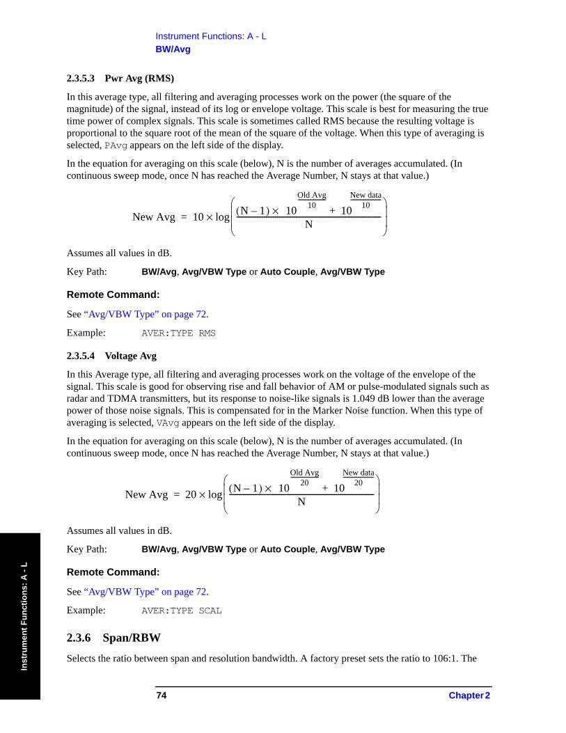
Instrument Functions: A - LBW/Avg
Inst
rum
ent F
unct
ions
: A -
L
2.3.5.3 Pwr Avg (RMS)
In this average type, all filtering and averaging processes work on the power (the square of the magnitude) of the signal, instead of its log or envelope voltage. This scale is best for measuring the true time power of complex signals. This scale is sometimes called RMS because the resulting voltage is proportional to the square root of the mean of the square of the voltage. When this type of averaging is selected, PAvg appears on the left side of the display.
In the equation for averaging on this scale (below), N is the number of averages accumulated. (In continuous sweep mode, once N has reached the Average Number, N stays at that value.)
Assumes all values in dB.
Key Path: BW/Avg, Avg/VBW Type or Auto Couple, Avg/VBW Type
Remote Command:
See “Avg/VBW Type” on page 72.
Example: AVER:TYPE RMS
2.3.5.4 Voltage Avg
In this Average type, all filtering and averaging processes work on the voltage of the envelope of the signal. This scale is good for observing rise and fall behavior of AM or pulse-modulated signals such as radar and TDMA transmitters, but its response to noise-like signals is 1.049 dB lower than the average power of those noise signals. This is compensated for in the Marker Noise function. When this type of averaging is selected, VAvg appears on the left side of the display.
In the equation for averaging on this scale (below), N is the number of averages accumulated. (In continuous sweep mode, once N has reached the Average Number, N stays at that value.)
Assumes all values in dB.
Key Path: BW/Avg, Avg/VBW Type or Auto Couple, Avg/VBW Type
Remote Command:
See “Avg/VBW Type” on page 72.
Example: AVER:TYPE SCAL
2.3.6 Span/RBW
Selects the ratio between span and resolution bandwidth. A factory preset sets the ratio to 106:1. The
New Avg 10 N 1–( ) 10×Old Avg
10--------------------
10New data
10----------------------
+N
------------------------------------------------------------------------------⎝ ⎠⎜ ⎟⎜ ⎟⎛ ⎞
log×=
New Avg 20 N 1–( ) 10×Old Avg
20--------------------
10New data
20----------------------
+N
------------------------------------------------------------------------------⎝ ⎠⎜ ⎟⎜ ⎟⎛ ⎞
log×=
74 Chapter 2
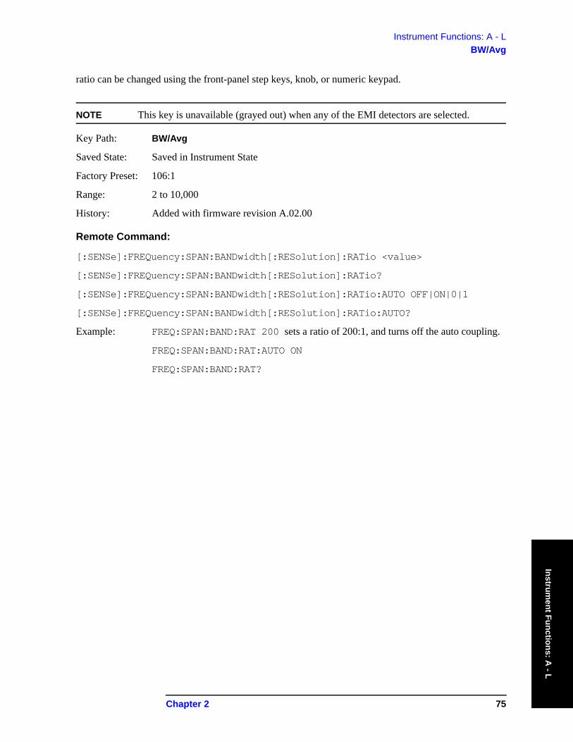
Instrument Functions: A - LBW/Avg
Instrument Functions: A
- L
ratio can be changed using the front-panel step keys, knob, or numeric keypad.
NOTE This key is unavailable (grayed out) when any of the EMI detectors are selected.
Key Path: BW/Avg
Saved State: Saved in Instrument State
Factory Preset: 106:1
Range: 2 to 10,000
History: Added with firmware revision A.02.00
Remote Command:
[:SENSe]:FREQuency:SPAN:BANDwidth[:RESolution]:RATio <value>
[:SENSe]:FREQuency:SPAN:BANDwidth[:RESolution]:RATio?
[:SENSe]:FREQuency:SPAN:BANDwidth[:RESolution]:RATio:AUTO OFF|ON|0|1
[:SENSe]:FREQuency:SPAN:BANDwidth[:RESolution]:RATio:AUTO?
Example: FREQ:SPAN:BAND:RAT 200 sets a ratio of 200:1, and turns off the auto coupling.
FREQ:SPAN:BAND:RAT:AUTO ON
FREQ:SPAN:BAND:RAT?
Chapter 2 75

Instrument Functions: A - LBW/Avg
Inst
rum
ent F
unct
ions
: A -
L
76 Chapter 2
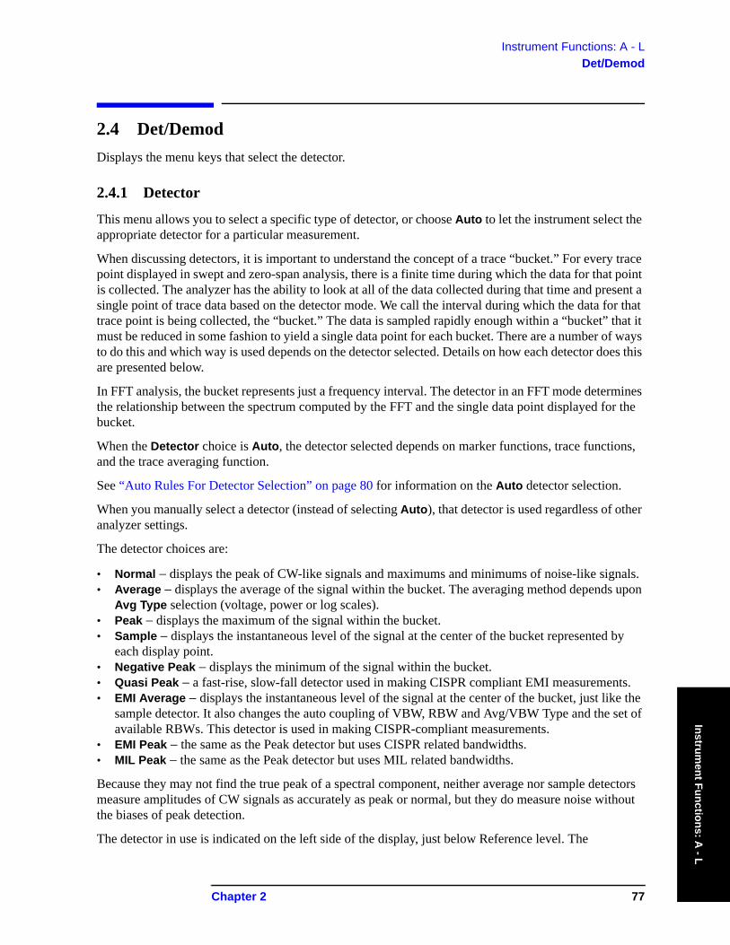
Instrument Functions: A - LDet/Demod
Instrument Functions: A
- L
2.4 Det/Demod Displays the menu keys that select the detector.
2.4.1 Detector
This menu allows you to select a specific type of detector, or choose Auto to let the instrument select the appropriate detector for a particular measurement.
When discussing detectors, it is important to understand the concept of a trace “bucket.” For every trace point displayed in swept and zero-span analysis, there is a finite time during which the data for that point is collected. The analyzer has the ability to look at all of the data collected during that time and present a single point of trace data based on the detector mode. We call the interval during which the data for that trace point is being collected, the “bucket.” The data is sampled rapidly enough within a “bucket” that it must be reduced in some fashion to yield a single data point for each bucket. There are a number of ways to do this and which way is used depends on the detector selected. Details on how each detector does this are presented below.
In FFT analysis, the bucket represents just a frequency interval. The detector in an FFT mode determines the relationship between the spectrum computed by the FFT and the single data point displayed for the bucket.
When the Detector choice is Auto, the detector selected depends on marker functions, trace functions, and the trace averaging function.
See “Auto Rules For Detector Selection” on page 80 for information on the Auto detector selection.
When you manually select a detector (instead of selecting Auto), that detector is used regardless of other analyzer settings.
The detector choices are:
• Normal − displays the peak of CW-like signals and maximums and minimums of noise-like signals. • Average − displays the average of the signal within the bucket. The averaging method depends upon
Avg Type selection (voltage, power or log scales).• Peak − displays the maximum of the signal within the bucket.• Sample − displays the instantaneous level of the signal at the center of the bucket represented by
each display point.• Negative Peak − displays the minimum of the signal within the bucket.• Quasi Peak − a fast-rise, slow-fall detector used in making CISPR compliant EMI measurements.• EMI Average − displays the instantaneous level of the signal at the center of the bucket, just like the
sample detector. It also changes the auto coupling of VBW, RBW and Avg/VBW Type and the set of available RBWs. This detector is used in making CISPR-compliant measurements.
• EMI Peak − the same as the Peak detector but uses CISPR related bandwidths.• MIL Peak − the same as the Peak detector but uses MIL related bandwidths.
Because they may not find the true peak of a spectral component, neither average nor sample detectors measure amplitudes of CW signals as accurately as peak or normal, but they do measure noise without the biases of peak detection.
The detector in use is indicated on the left side of the display, just below Reference level. The
Chapter 2 77

Instrument Functions: A - LDet/Demod
Inst
rum
ent F
unct
ions
: A -
L
designators are:
• Norm − Normal detector• Avg − Average detector• Peak − Peak detector• Samp − Sample detector• NPk − Negative Peak detector• EmiQP − Quasi Peak detector• EmiAv − ΕMI Average detector• EmiPk − Peak detector with CISPR bandwidths• MILPk − Peak detector with MIL bandwidths
If the detector has been manually selected, a # appears next to it.
TIP RMS Detection
To measure the average power (RMS voltage) in each display point, set Detector to Average, and verify that Avg/VBW Type is set to Pwr Avg (RMS).
Key Path: Det/Demod
State Saved: Saved in Instrument State
Factory Preset: Normal, Auto Coupled
Remote Command:
[:SENSe]:DETector[:FUNCtion] NORMal|AVERage|POSitive|SAMPle|NEGative|QPEak |EAVerage|EPOSitive|MPOSitiv|RMS
[:SENSe]:DETector[:FUNCtion]?
The query returns a name that corresponds to the detector mode as shown by the following terms:
Remote Command
NORMal Normal
AVERage Average
POSitive Peak
SAMPle Sample
NEGative Negative peak
QPEak Quasi Peak
EAVerage EMI Average
EPOSitive EMI Peak
MPOSitive MIL Peak
RMS RMS (alias)
78 Chapter 2
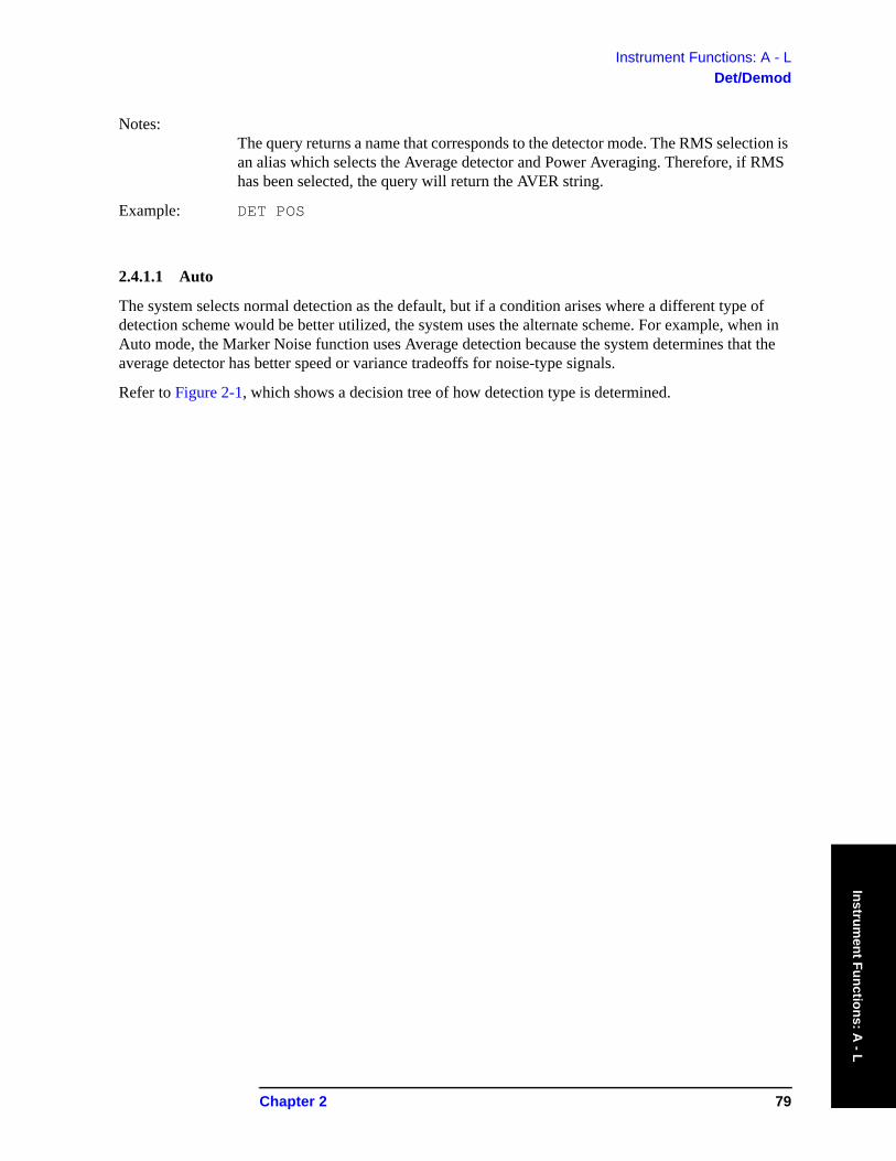
Instrument Functions: A - LDet/Demod
Instrument Functions: A
- L
Notes: The query returns a name that corresponds to the detector mode. The RMS selection is an alias which selects the Average detector and Power Averaging. Therefore, if RMS has been selected, the query will return the AVER string.
Example: DET POS
2.4.1.1 Auto
The system selects normal detection as the default, but if a condition arises where a different type of detection scheme would be better utilized, the system uses the alternate scheme. For example, when in Auto mode, the Marker Noise function uses Average detection because the system determines that the average detector has better speed or variance tradeoffs for noise-type signals.
Refer to Figure 2-1, which shows a decision tree of how detection type is determined.
Chapter 2 79
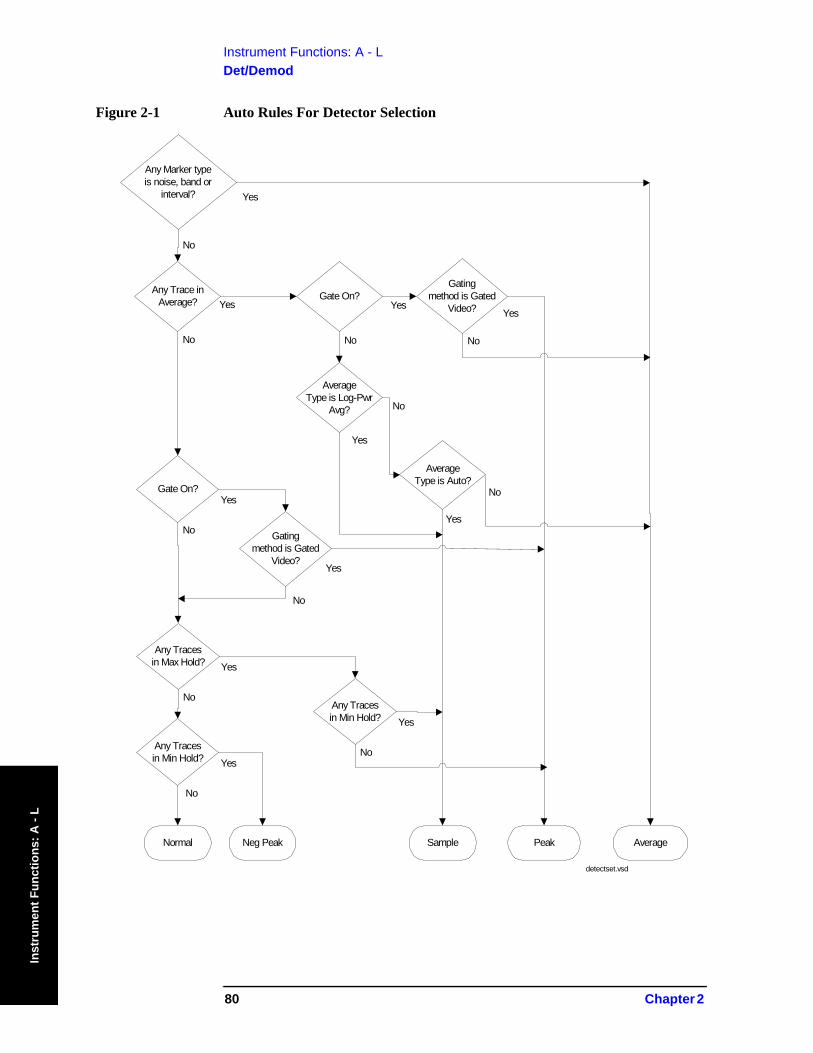
Instrument Functions: A - LDet/Demod
Inst
rum
ent F
unct
ions
: A -
L
Figure 2-1 Auto Rules For Detector Selection
Any Marker typeis noise, band or
interval?
Any Trace inAverage?
Gate On?
AverageSample
No
No
No
Yes
Yes
Yes
detectset.vsd
Gate On?
No
Yes
Gatingmethod is Gated
Video?
No
Yes
Peak
AverageType is Log-Pwr
Avg?
Yes
No
AverageType is Auto?
Yes
No
Gatingmethod is Gated
Video?
No
Yes
Any Tracesin Max Hold?
No
Yes
Any Tracesin Min Hold?
No
Yes
Any Tracesin Min Hold?
No
Yes
Normal Neg Peak
80 Chapter 2
Instrument Functions: A - LDet/Demod
Instrument Functions: A
- L
Key Path: Det/Demod
Factory Preset: On, Normal
Remote Command:
[:SENSe]:DETector:AUTO OFF|ON|0|1
[:SENSe]:DETector:AUTO?
Example: DET:AUTO ON
2.4.1.2 Normal
Displays the peak-detected level in the interval (bucket) being displayed when the signal is CW-like. If the signal is noise-like (within a bucket the signal both rose and fell), the even bucket shows the peak (maximum) within a two-bucket interval, and the odd bucket shows the negative peak (minimum). Gain is increased to compensate for the effects of faster sweep rates, to keep the displayed value of CW signals accurate.
When Normal is selected, Norm appears on the left side of the display.
Key Path: Det/Demod
Remote Command:
See “Detector” on page 77.
Example: DET NORM
2.4.1.3 Average
For each interval (bucket) in the trace, Average detection displays the average of all samples within the interval using one of the following averaging methods:
• log (also known as video)
• power (also known as RMS)
• voltage envelope
To explicitly set the averaging method, use the BW/Avg, Avg/VBW Type key. The combination of the average detector and the power method is equivalent to what is sometimes referred to as “RMS detection.” When the method (Avg/VBW Type) is set to Pwr Avg, and Detector is set to Average, the RMS method is selected.
When Average is selected, Avg appears on the left side of the display.
Key Path: Det/Demod
Dependencies/ Couplings: Use of Average affects the VBW setting. See the section “Video BW” on page 68.
When in Average detection, video trigger is not available.
Chapter 2 81
Instrument Functions: A - LDet/Demod
Inst
rum
ent F
unct
ions
: A -
L
Remote Command:
See “Detector” on page 77.
Example: DET AVER
2.4.1.4 Peak
For each interval (bucket) in the trace, Peak detection displays the highest amplitude within the interval. Peak detection is used for CW measurements and some pulsed-RF measurements. For swept analysis, peak detection basically obtains the maximum video signal between the end of the previous bucket and the end of the current one. Gain is increased to compensate for the effects of faster sweep rates, to keep the displayed value accurate. For FFT analysis, the highest spectral amplitude is displayed, even if that peak amplitude falls between samples of the spectrum computed in the FFT process.
When Peak is selected, Peak appears on the left side of the display.
Key Path: Det/Demod
Remote Command:
See “Detector” on page 77.
Example: DET POS
2.4.1.5 Sample
The sample detector displays the instantaneous level of the signal at the center of the interval (bucket) represented by each trace point.
Sample detection is primarily used to display noise or noise-like signals.
Sample detection is not best for amplitude measurements of CW-like signals for two reasons. First, the peak response to a signal can occur between samples, so unless the Span to RBW ratio is lower than usual, the highest sample can be well below the peak signal amplitude. Second, for the high sweep rates normally used, the peak response of the RBW filters is up to –0.5 dB. This sweeping error is compensated when using the peak and normal detectors by changing the overall gain. But the gain is not changed when in the sample detector, because to do so would cause errors in the response to noise.
When Sample is selected, Samp appears on the left side of the display.
Key Path: Det/Demod
Remote Command:
See “Detector” on page 77.
Example: DET SAMP
82 Chapter 2
Instrument Functions: A - LDet/Demod
Instrument Functions: A
- L
2.4.1.6 Negative Peak
For each interval (bucket) in the trace, Negative Peak detection displays the lowest sample within the interval.
When Negative Peak is selected, NPk appears on the left side of the display.
Key Path: Det/Demod
Remote Command:
See “Detector” on page 77.
Example: DET NEG
2.4.1.7 Quasi Peak
Selects quasi peak detection. This is a fast-rise, slow-fall detector used in making CISPR compliant EMI measurements. Quasi peak detection displays a weighted amplitude using specific charge, discharge, and meter-movement time constants as described in CISPR Publication 16.
Key Path: Det/Demod
Dependencies/ Couplings: Whenever the quasi peak detector is selected, the resolution bandwidths available will
be the CISPR set described in the tables below. If the FFT and Sweep setting is Manual:FFT Quasi Peak is grayed out.
Table 2-2 CISPR Bandwidths with RBW Set to Auto
Band Start Frequency Stop Frequency
Bandwidth
A 10 kHz 150 kHz 200 Hz
B 150 kHz 30 MHz 9 kHz
C & D 30 MHz 1 GHz 120 kHz
Table 2-3 CISPR Bandwidths with RBW Set to Manual
RBW, Hz Type Equivalent –3 dB BW Filter
10 –6 dB 6.8 Hz
30 –6 dB 20 Hz
100 −6 dB 68 Hz
200 CISPR 150 Hz
300 –6 dB 200Hz
1 k –6 dB 680 Hz
Chapter 2 83
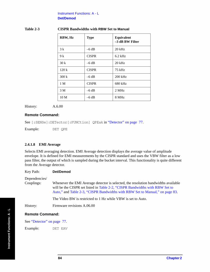
Instrument Functions: A - LDet/Demod
Inst
rum
ent F
unct
ions
: A -
L
History: A.6.00
Remote Command:
See [:SENSe]:DETector[:FUNCtion] QPEak in “Detector” on page 77.
Example: DET QPE
2.4.1.8 EMI Average
Selects EMI averaging detection. EMI Average detection displays the average value of amplitude envelope. It is defined for EMI measurements by the CISPR standard and uses the VBW filter as a low pass filter, the output of which is sampled during the bucket interval. This functionality is quite different from the Average detector.
Key Path: Det/Demod
Dependencies/ Couplings: Whenever the EMI Average detector is selected, the resolution bandwidths available
will be the CISPR set listed in Table 2-2, “CISPR Bandwidths with RBW Set to Auto,” and Table 2-3, “CISPR Bandwidths with RBW Set to Manual,” on page 83.
The Video BW is restricted to 1 Hz while VBW is set to Auto.
History: Firmware revisions A.06.00
Remote Command:
See “Detector” on page 77.
Example: DET EAV
3 k –6 dB 20 kHz
9 k CISPR 6.2 kHz
30 k –6 dB 20 kHz
120 k CISPR 75 kHz
300 k –6 dB 200 kHz
1 M CISPR 680 kHz
3 M –6 dB 2 MHz
10 M –6 dB 8 MHz
Table 2-3 CISPR Bandwidths with RBW Set to Manual
RBW, Hz Type Equivalent –3 dB BW Filter
84 Chapter 2
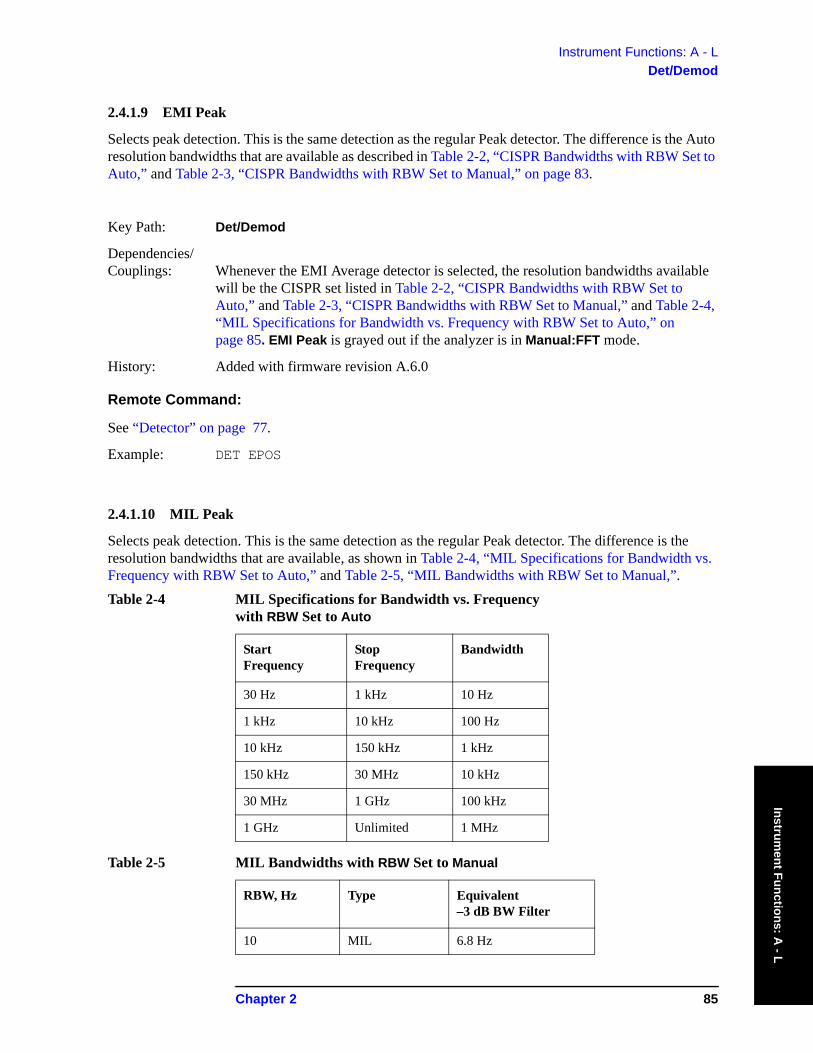
Instrument Functions: A - LDet/Demod
Instrument Functions: A
- L
2.4.1.9 EMI Peak
Selects peak detection. This is the same detection as the regular Peak detector. The difference is the Auto resolution bandwidths that are available as described in Table 2-2, “CISPR Bandwidths with RBW Set to Auto,” and Table 2-3, “CISPR Bandwidths with RBW Set to Manual,” on page 83.
Key Path: Det/Demod
Dependencies/ Couplings: Whenever the EMI Average detector is selected, the resolution bandwidths available
will be the CISPR set listed in Table 2-2, “CISPR Bandwidths with RBW Set to Auto,” and Table 2-3, “CISPR Bandwidths with RBW Set to Manual,” and Table 2-4, “MIL Specifications for Bandwidth vs. Frequency with RBW Set to Auto,” on page 85. EMI Peak is grayed out if the analyzer is in Manual:FFT mode.
History: Added with firmware revision A.6.0
Remote Command:
See “Detector” on page 77.
Example: DET EPOS
2.4.1.10 MIL Peak
Selects peak detection. This is the same detection as the regular Peak detector. The difference is the resolution bandwidths that are available, as shown in Table 2-4, “MIL Specifications for Bandwidth vs. Frequency with RBW Set to Auto,” and Table 2-5, “MIL Bandwidths with RBW Set to Manual,”.Table 2-4 MIL Specifications for Bandwidth vs. Frequency
with RBW Set to Auto
Start Frequency
Stop Frequency
Bandwidth
30 Hz 1 kHz 10 Hz
1 kHz 10 kHz 100 Hz
10 kHz 150 kHz 1 kHz
150 kHz 30 MHz 10 kHz
30 MHz 1 GHz 100 kHz
1 GHz Unlimited 1 MHz
Table 2-5 MIL Bandwidths with RBW Set to Manual
RBW, Hz Type Equivalent –3 dB BW Filter
10 MIL 6.8 Hz
Chapter 2 85
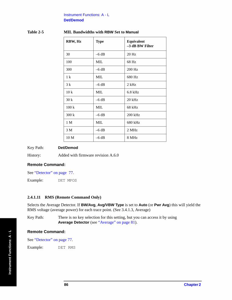
Instrument Functions: A - LDet/Demod
Inst
rum
ent F
unct
ions
: A -
L
Key Path: Det/Demod
History: Added with firmware revision A.6.0
Remote Command:
See “Detector” on page 77.
Example: DET MPOS
2.4.1.11 RMS (Remote Command Only)
Selects the Average Detector. If BW/Avg, Avg/VBW Type is set to Auto (or Pwr Avg) this will yield the RMS voltage (average power) for each trace point. (See 3.4.1.3, Average)
Key Path: There is no key selection for this setting, but you can access it by using Average Detector (see “Average” on page 81).
Remote Command:
See “Detector” on page 77.
Example: DET RMS
30 –6 dB 20 Hz
100 MIL 68 Hz
300 –6 dB 200 Hz
1 k MIL 680 Hz
3 k –6 dB 2 kHz
10 k MIL 6.8 kHz
30 k –6 dB 20 kHz
100 k MIL 68 kHz
300 k –6 dB 200 kHz
1 M MIL 680 kHz
3 M –6 dB 2 MHz
10 M –6 dB 8 MHz
Table 2-5 MIL Bandwidths with RBW Set to Manual
RBW, Hz Type Equivalent –3 dB BW Filter
86 Chapter 2
Instrument Functions: A - LDisplay
Instrument Functions: A
- L
2.5 DisplayDisplays menu keys that enable you to control certain items on the display of the analyzer.
NOTE CCDF and SEM measurements have measurement specific Display menus. For the Display description for a CCDF or SEM measurement, see the One-Button Measurements User’s and Programmer’s guide.
Key Path: Front-panel key
2.5.1 Full Screen
When Full Screen is pressed the measurement window expands horizontally over the entire instrument display. It turns on/off the display of the softkey labels. Pressing any other key that results in a new menu will cancel the full screen function.
Key Path: Display
State Saved: Not saved in state.
Factory Preset: Off
Factory Default: Off
History: Added with firmware revision A.02.00
Remote Command:
:DISPlay:FSCReen[:STATe] OFF|ON|0|1
:DISPlay:FSCReen[:STATe]?
Example: DISP:FSCR ON
2.5.2 Display Line
Activates an adjustable horizontal line that is used as a visual reference line. The line has an amplitude value that corresponds to its vertical position relative to the reference level. The value of the display line appears on the left side of the display below the label Dl. The display line can be adjusted using the step keys, knob, or numeric keypad. The units of Display Line are determined by the Y-Axis Units setting under Amplitude.
Key Path: Display
State Saved: Saved in Instrument State.
Factory Preset: –25 dBm, Off
Factory Default: –25 dBm, Off
Chapter 2 87
Instrument Functions: A - LDisplay
Inst
rum
ent F
unct
ions
: A -
L
Terminators: dBm, mV, uV
Range: −370 dBm to 30 dBm
Remote Command:
:DISPlay:WINDow:TRACe:Y:DLINe <ampl>
:DISPlay:WINDow:TRACe:Y:DLINe?
:DISPlay:WINDow:TRACe:Y:DLINe:STATe OFF|ON|0|1
:DISPlay:WINDow:TRACe:Y:DLINe:STATe?
Example: :DISP:WIND:TRAC:Y:DLIN -32 dBm
:DISP:WIND:TRAC:Y:DLIN:STAT OFF
2.5.3 Active Fctn Position
Selects the screen position for the Active Function Display. Depending on the type of trace date being viewed, you can move the Active Function Display position for less visual interference with your screen data.
Key Path: Display
Readback: The selection of the position to display the active function (Top, Center, Bottom) reads back to line 3 of this key.
State Saved: Not saved in instrument state, survives power cycle and preset.
Factory Preset: No effect, persistent variable, survives power cycle and preset.
Factory Default: Center. Pressing System, Restore Sys Defaults will reset to factory defaults.
History: Added with firmware revision A.04.00
Remote Command:
:DISPlay:AFUNction:POSition BOTTom|CENTer|TOP
:DISPlay:AFUNction:POSition?
Example: :DISP:AFUN:POS BOT
88 Chapter 2
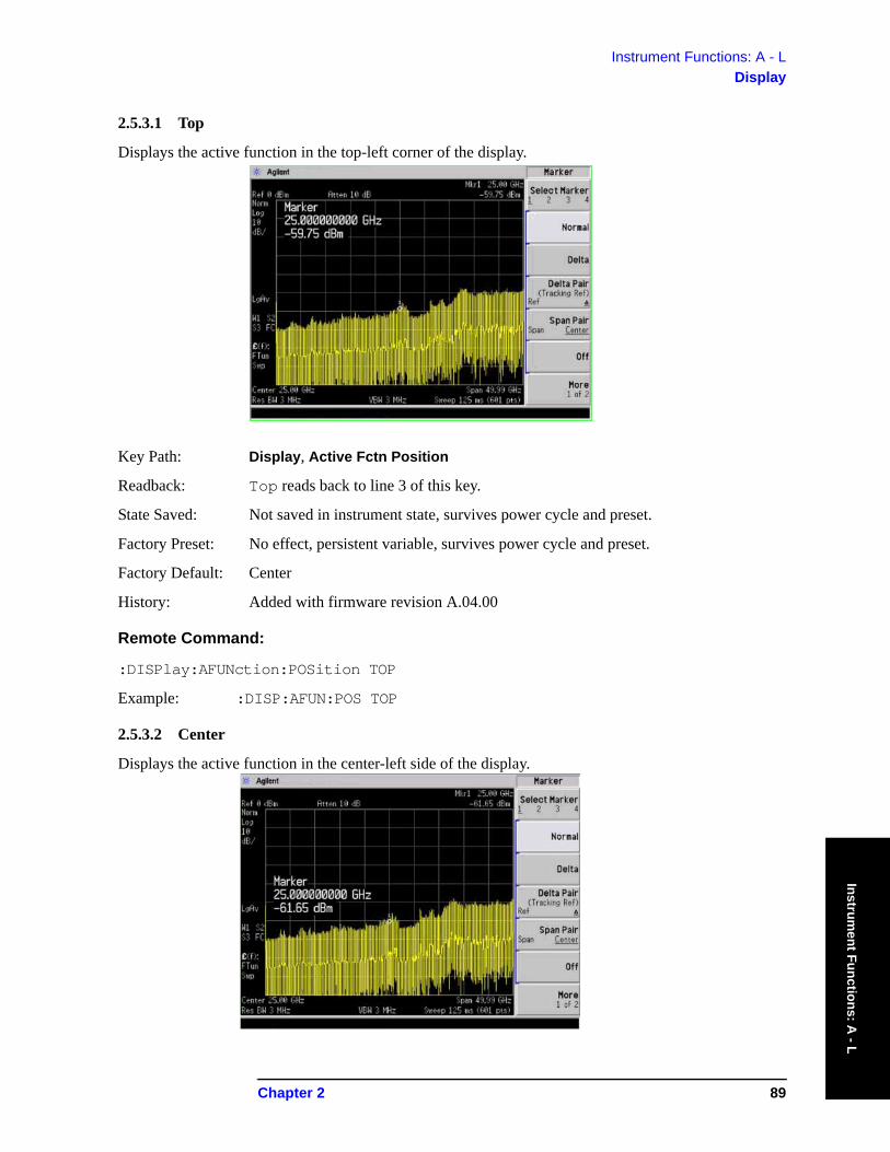
Instrument Functions: A - LDisplay
Instrument Functions: A
- L
2.5.3.1 Top
Displays the active function in the top-left corner of the display.
Key Path: Display, Active Fctn Position
Readback: Top reads back to line 3 of this key.
State Saved: Not saved in instrument state, survives power cycle and preset.
Factory Preset: No effect, persistent variable, survives power cycle and preset.
Factory Default: Center
History: Added with firmware revision A.04.00
Remote Command:
:DISPlay:AFUNction:POSition TOP
Example: :DISP:AFUN:POS TOP
2.5.3.2 Center
Displays the active function in the center-left side of the display.
Chapter 2 89
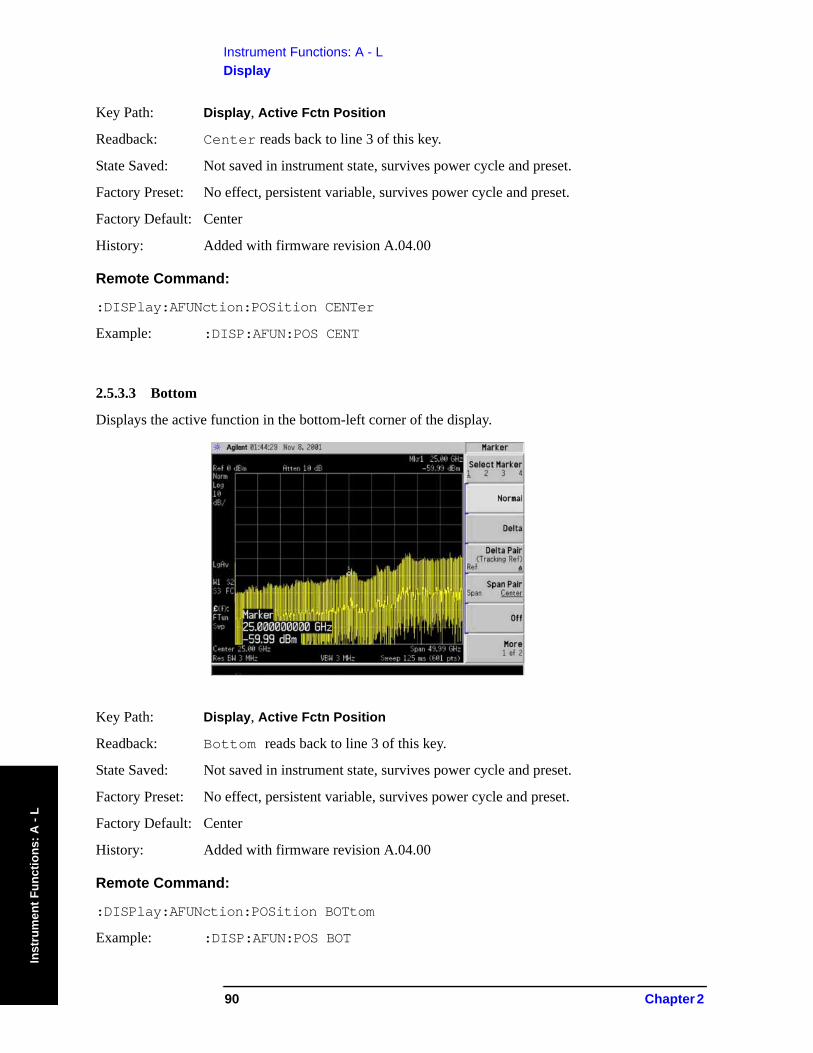
Instrument Functions: A - LDisplay
Inst
rum
ent F
unct
ions
: A -
L
Key Path: Display, Active Fctn Position
Readback: Center reads back to line 3 of this key.
State Saved: Not saved in instrument state, survives power cycle and preset.
Factory Preset: No effect, persistent variable, survives power cycle and preset.
Factory Default: Center
History: Added with firmware revision A.04.00
Remote Command:
:DISPlay:AFUNction:POSition CENTer
Example: :DISP:AFUN:POS CENT
2.5.3.3 Bottom
Displays the active function in the bottom-left corner of the display.
Key Path: Display, Active Fctn Position
Readback: Bottom reads back to line 3 of this key.
State Saved: Not saved in instrument state, survives power cycle and preset.
Factory Preset: No effect, persistent variable, survives power cycle and preset.
Factory Default: Center
History: Added with firmware revision A.04.00
Remote Command:
:DISPlay:AFUNction:POSition BOTtom
Example: :DISP:AFUN:POS BOT
90 Chapter 2
Instrument Functions: A - LDisplay
Instrument Functions: A
- L
2.5.4 Limits
Limit lines can be defined to compare the data to your defined limits and indicate a pass or fail condition. Limits accesses menus that allow you to create, modify, and change the properties of limit lines. There are two limit lines in the instrument.
Key Path: Display
State Saved: Not saved in instrument state.
SCPI Status Bits/ OPC Dependencies: No OPC dependencies.
Factory Default: Unaffected by system defaults.
History: Added with firmware revision A.03.00
Remote Command:
:CALCulate:LLINe[1]|2:DATA <x-axis>, <ampl>, <connected>{,<x-axis>,<ampl>,<connected>}
:CALCulate:LLINe[1]|2:DATA?
Defines the limit line values, and destroys all existing data. Up to 200 points may be defined for each limit using the following parameters.
<x-axis> can be frequency or time values as specified by the following command: :Calculate:LLINe:CONTrol:DOMain. Frequencies are always in Hz. Time is always in seconds. No unit is allowed in this parameter.
Range: –1000 Ms to 1000 Ms for time limits, -3 kHz to +350 GHz for frequency limits.
<ampl> amplitude values are always in units of dBm. Up to two amplitude values can be provided for each x-axis value, by repeating <x-axis> in the data list. No unit is allowed in this parameter.
Range: -140 dBm to +100 dBm
<connected> connected values are either "0" or "1". A "1" means this point should be connected to the previously defined point to define the limit line. A "0" means that it is a point of discontinuity and is not connected to the preceding point. The connected value is ignored for the first point.
:CALCulate:LLINe[1]|2:DATA:MERGe <x-axis>, <ampl>, <connected>{,<x-axis>,<ampl>,<connected>}
Adds the points with the specified values to the current limit line, allowing you to merge limit line data. Up to two amplitude values are allowed for each x value. If more than 200 points are entered to be merged, the first 200 points are merged into the existing limit, then an error ‘too many DATA entries’ is reported.
Remote Command Notes: Up to 200 points total may be defined for each limit.
Example: CALC:LLIN1:DATA 1000000000, -20,0,200000000,-30,1
Chapter 2 91
Instrument Functions: A - LDisplay
Inst
rum
ent F
unct
ions
: A -
L
2.5.4.1 Limit 1 or Limit 2
Selects Limit 1 or Limit 2 for modification.
Key Path: Display, Limits
State Saved: Not saved in instrument state.
History: Added with firmware revision A.03.00
2.5.4.1.1 Type (Upper Lower)
Allows you to define the limit you are editing as either an upper or lower limit. An Upper limit fails if the trace exceeds the limit. A Lower limit fails if the trace falls below the limit.
Key Path: Display, Limits, Limit 1
Display, Limits, Limit 2
Dependencies/ Couplings: If a margin has already been set for this limit line, and this key is used to change the
limit type, then the margin value is reset to 0 dB.
State Saved: Not saved in instrument state. Survives power cycle and preset. The limit-line data is saved in files.
Factory Preset and *RST: Not affected by preset.
Factory Default: Limits are off by default. Upper for Limit 1, then a limit line is created. Lower for Limit 2, then a limit line is created.
History: Added with firmware revision A.03.00
Remote Command:
:CALCulate:LLINe[1]|2:TYPE UPPer|LOWer
:CALCulate:LLINe[1]|2:TYPE?
Example: :CALC:LLIN2:TYPE LOW sets limit line 2 as a lower limit.
:CALC:LLIN1:TYPE? responds with the limit line 1 limit type.
2.5.4.1.2 Limit Display
Turns limit-line display On or Off. Either Limit or Margin, as well as Test, must be turned on to turn on a limit test.
Key Path: Display, Limits, Limit 1
Display, Limits, Limit 2
State Saved: Not saved in instrument state.
92 Chapter 2
Instrument Functions: A - LDisplay
Instrument Functions: A
- L
SCPI Status Bits/ OPC Dependencies: No OPC dependencies.
Factory Preset and *RST: Off
Factory Default: Off (when a limit line is created)
History: Added with firmware revision A.03.00
Remote Command:
:CALCulate:LLINe[1]|2:DISPlay OFF|ON|0|1
:CALCulate:LLINe[1]|2:DISPlay? queries the current limit line.
Example: :CALC:LLIN2:DISP OFF turns off the display of the limit lines.
:CALC:LLIN1:DISP? tells you whether the limit lines are being displayed.
2.5.4.1.3 Limit Test
Turns the testing of the limit line On or Off. If the trace is at or within the bounds of the set limit or margin, PASS LIMIT# or PASS MARGIN# is displayed in green in the upper-left corner of the measurement area where # is the number of the selected limit line.
Only positive margins are allowed for lower limits and only negative margins are allowed for upper limits. If the trace is out of the limit or margin boundaries, FAIL LIMIT# or FAIL MARGIN# is displayed in red. The results for Limit 2 are displayed below those for Limit 1. Either Limit or Margin must be turned on for Test to be turned on.
NOTE The color of your screen annotation is dependent on your analyzer settings and may not correspond to the colors described above.
Key Path: Display, Limits, Limit 1
Display, Limits, Limit 2
Dependencies/ Couplings: If either of the limits or margins are turned off, the test cannot be turned on. That is, if
both Limit and Margin are set to Off, then the test is turned off automatically.
State Saved: Not saved in instrument state.
Factory Preset and *RST: Off
Factory Default: Off (when a limit line is created)
History: Added with firmware revision A.03.00
Chapter 2 93
Instrument Functions: A - LDisplay
Inst
rum
ent F
unct
ions
: A -
L
Remote Command:
:CALCulate:LLINe[1]|2:STATe OFF|ON|0|1 to turn limit lines on or off.
:CALCulate:LLINe[1]|2:STATe?
:CALCulate:LLINe[1]|2:FAIL?
Example: :CALC:LLIN:STATE 1 sets limit line 1 test on.
:CALC:LLIN:STATE? responds with the limit line test status.
:CALC:LLIN:FAIL? Queries the status of the limit-line testing. Returns a "0" if the data passes, and returns a "1" if there is a failure. This query value is valid only if Margin or Test is On.
2.5.4.1.4 Margin (On Off)
Turns margin On or Off. Selecting On allows you to set a limit-line offset for the selected limit line. Only positive margins are allowed for lower limits and only negative margins are allowed for upper limits. The margin lines are displayed in a light gray color. If the limit lines are off and margin is on, the trace is checked against the margin, then a pass or fail margin is displayed. Either Limit or Margin, as well as Test, must be turned on to turn on a limit test.
Key Path: Display, Limits, Limit 1
Display, Limits, Limit 2
Dependencies/ Couplings: If neither of the limits or margins are turned on, the test cannot be turned on. That is, if
both Limit and Margin are set to Off, then the test is turned off automatically. If a margin has been set for this limit line, and this key is used to change the limit type, then the margin values is reset to 0 dB.
State Saved: Not saved in instrument state. Survives preset and power cycle.
Factory Preset and *RST: Off
Factory Default: Off (when a limit line is created). Default value is not affected by a preset.
Fundamental Units: dB
Terminators: dB, −dB
Default Terminator: dB
Resolution: 0.1 dB
Knob Increment: −0.1 dB (Upper); 0.1 dB (Lower)
Step Key Increment: −1 dB (Upper); 1 dB (Lower)
Range: 0 to −40 dB (Upper); 0 to 40 dB (Lower)
History: Added with firmware revision A.03.00
94 Chapter 2
Instrument Functions: A - LDisplay
Instrument Functions: A
- L
Remote Command:
:CALCulate:LLINe[1]|2:MARGin:STATe OFF|ON|0|1 turns on margins on or off. If the margin and limit display are both turned off, limit test is automatically turned off.
:CALCulate:LLINe[1]|2:MARGin:STATe?
Responds with the margin state; 0 = off 1 = on.
:CALCulate:LLINe[1]|2:MARGin <ampl_rel>
Defines the amount of measurement margin that is added to the designated limit line.
:CALCulate:LLINe[1]|2:MARGin?
Returns the margin offset value.
2.5.4.1.5 Edit
Pressing Edit accesses menus for editing limit lines and for accessing the limit-line table editor. Navigation through the limit-line table is achieved by using the front-panel arrow and tab keys. Entering data in each field navigates to the next field. New limit segments will only be applied after the editor is closed.
Pressing Return, or any key that is not associated with the editor, will close the limit-line table editor.
NOTE Refer to your Getting Started guide for more information about navigation within tables using your front-panel arrow and tab keys.
Key Path: Display, Limits, Limit 1
Display, Limits, Limit 2
Factory Preset and *RST: Exits the edit mode.
History: Added with firmware revision A.03.00
2.5.4.1.5.1 Point
Up to 200 points may be defined for each limit line using Point. A maximum of two different points may be entered that have the same frequency. Enter the point number to be created or edited using the numeric keypad, then press Enter, or use the front-panel knob, or step keys to move to an existing point. The step-up key takes you to the next point, while the step-down key takes you to the previous point. After selecting a point, Frequency (or Time, depending on x-axis selection) becomes active.
Key Path: Display, Limits, Limit 1, Edit
Display, Limits, Limit 2, Edit
State Saved: Not affected by state.
Chapter 2 95
Instrument Functions: A - LDisplay
Inst
rum
ent F
unct
ions
: A -
L
Factory Preset and *RST: 1
Terminators: Enter
Default Terminator: Enter
Resolution: 1
Knob Increment: 1
Step Key Increment: 1
History: Added with firmware revision A.03.00
Range: 1 to 200
2.5.4.1.5.2 Frequency (or Time)
Pressing this key allows you to enter a value for a limit point in frequency (or time). Note that this key label changes to Time if X Axis Units has been selected. After entering a value, the limit table is sorted to place the value in the correct order. A maximum of two different points may be entered that have the same frequency. For a new point, Amplitude defaults to 0 dBm and Connected defaults to Yes. Amplitude then becomes active.
Key Path: Display, Limits, Limit 1, Edit
Display, Limits, Limit 2, Edit
Dependencies/ Couplings: Limit-line points are selected according to the X-axis units selected, for example if
frequency is selected as your X-axis units, then the limit points are frequency values. Also, if both upper and lower limit lines are selected for the trace then both need to be defined using the same X-axis units.
Fundamental Units: Hz, s
Factory Preset and *RST: 300 MHz; 120 Ms
Terminators: Hz, s
Default Terminator: Hz (frequency), s (time)
Knob Increment: 0.2 MHz, 30 Ms
Step Key Increment: 20 MHz, 12 Ms
Range: –3 kHz to 350 GHz; –1000 Msec to 1000 Msec
History: Added with firmware revision A.03.00
96 Chapter 2
Instrument Functions: A - LDisplay
Instrument Functions: A
- L
2.5.4.1.5.3 Amplitude
Pressing Amplitude allows you to enter the amplitude value for the current limit point. After entering a value, Connected becomes active. If a front-panel arrow key is pressed without entering a value, the current Amplitude and Connected values of the point are selected. If the up arrow is pressed, the point number automatically increments to allow entry of the amplitude of the next point. If it is a new point, the Frequency may also be entered for the new point.
Key Path:. Display, Limits, Limit 1, Edit
Display, Limits, Limit 2, Edit
Factory Preset and *RST:. 0 dBm
Fundamental Units:. dBm
Terminators:. dBm
Default Terminator:. dBm
Resolution:. 0.1 dBm
Knob Increment:. 0.1 dBm
Step Key Increment:. 10 dBm
Range:. -140 dBm to 100 dBm
History:. Added with firmware revision A.03.00
2.5.4.1.5.4 Connected To Previous Pt
A current point may be connected to the previous point by pressing Yes. No limit testing is performed between disconnected points. Pressing this key when the Connected field is selected toggles the connected value of the current point and increments the Point number to allow entry or editing of the Frequency of the next point. If an arrow key is pressed without entering a value, the current Connected value of the point is selected. If an arrow key is pressed, the Point number automatically increments to allow entry of the Connected value of the next point. If it is a new point, the Frequency may be entered for the new point.
Key Path:. Display, Limits, Limit 1, Edit
Display, Limits, Limit 2, Edit
Factory Preset and *RST:. Yes
Knob Increment:. Toggles to other selection.
Step Key Increment:. Toggles to other selection
History:. Added with firmware revision A.03.00
Chapter 2 97
Instrument Functions: A - LDisplay
Inst
rum
ent F
unct
ions
: A -
L
2.5.4.1.5.5 Delete Point
Deleting the current limit point can be achieved by pressing Delete Point. You will be prompted with the message If you are sure, press key again to delete. Pressing Delete Point again will delete the limit point.
Key Path:. Display, Limits, Limit 1, Edit
Display, Limits, Limit 2, Edit
History:. Added with firmware revision A.03.00
2.5.4.1.6 Delete Limit
Deleting the current limit set can be achieved by pressing Delete. You will be prompted with the message If you are sure, press key again to delete. Pressing Delete again will delete the limit set.
Key Path: Display, Limits, Limit 1
Display, Limits, Limit 2
Factory Preset and *RST: Off
History: Added with firmware revision A.03.00
Remote Command:
:CALCulate:LLINe[1]|2:DELete
Example: :CALC:LLIN:DEL deletes limit line/margin 1 (LLIN defaults to Limit Line 1)
2.5.4.1.7 Freq Interp
This key is grayed out if Time is the selected X Axis Units. Sets the interpolation to linear or logarithmic for the specified limiting points set, allowing you to determine how limit trace values are computed between points in a limit table. The available interpolation modes are linear and logarithmic. If the linear (Lin) mode is used for both frequency and amplitude, a straight line is used when interpolating between points in a limit table. If frequency interpolation is logarithmic (Log), frequency values between limit points are computed by first taking the logarithm of both the table values and the intermediate value. A linear interpolation is then performed in this logarithmic frequency space. An exactly analogous manipulation is done for logarithmic amplitude interpolation.
98 Chapter 2

Instrument Functions: A - LDisplay
Instrument Functions: A
- L
NOTE If two amplitude values are entered for the same frequency, a single vertical line is the result. In this case, if an upper line is chosen, the amplitude of lesser frequency (amplitude 1) is tested. If a lower line is chosen, the amplitude of greater frequency (amplitude 2) is tested.
For linear amplitude interpolation and linear frequency interpolation, the interpolation is computed as:
For linear amplitude interpolation and log frequency interpolation, the interpolation is computed as:
For log amplitude interpolation and linear frequency interpolation, the interpolation is computed as:
For log amplitude interpolation and log frequency interpolation, the interpolation is computed as:
Key Path: Display, Limits, Limit 1
Display, Limits, Limit 2
State Saved: Persistent; retains settings, even through a power cycle.
Factory Preset and *RST: Log
History: Added with firmware revision A.03.00
Remote Command:
:CALCulate:LLINe[1]|2:CONTrol:INTerpolate:TYPE LOGarithmic|LINear
:CALCulate:LLINe[1]|2:CONTrol:INTerpolate:TYPE?
Example: :CALC:LLIN2:CONT:INT:TYPE LIN sets limit line 2 frequency interpolation to linear.
yyi 1+ yi–fi 1+ fi–---------------------- f fi–( ) yi+=
yyi 1+ yi–
log fi 1+ log fi–--------------------------------------- log f log fi–( ) yi+=
log ylog yi 1+ log yi–
fi 1+ fi–----------------------------------------- f fi–( ) log yi+=
log ylog yi 1+ log yi–log fi 1+ log fi–----------------------------------------- log f log fi–( ) ylog i+=
Chapter 2 99
Instrument Functions: A - LDisplay
Inst
rum
ent F
unct
ions
: A -
L
2.5.4.1.8 Amptd Interp
Allows you to determine how limit trace values are computed between points in a limit table. The available interpolation modes are linear (Lin) and logarithmic (Log). If the linear mode is used for both frequency and amplitude, a straight line is used when interpolating between points in a limit table. This function does not work in zero span (when the analyzer is in time domain). Refer to the "Note" in “Freq Interp” on page 98 for more information.
NOTE Interpolation modes determine how limit values are computed between points in the limit table. The appearance of a limit trace is also affected by the amplitude scale, which may be linear or logarithmic.
Key Path: Display, Limits, Limit 1
Display, Limits, Limit 2
State Saved: Persistent; retains settings, even through a power cycle.
Factory Preset and *RST: Not affected by preset
Factory Default: Log for a new limit.
History: Added with firmware revision A.03.00
Remote Command:
:CALCulate:LLINe[1]|2:AMPLitude:INTerpolate:TYPE LOGarithmic|LINear
:CALCulate:LLINe[1]|2:AMPLitude:INTerpolate:TYPE?
Example: :CALC:LLIN:AMPLLINT:TYPE LOG sets limit line 1 amplitude interpolation to LOG.
:CALC:LLIN:AMPLLINT:TYPE? responds with the limit line interpolation type.
2.5.4.2 X Axis Units
Selects how the limit-line segments are defined. Pressing X Axis Units selects whether the limit lines will be entered using frequency (Freq) or sweep time (Time) to define the segments. They can be specified as a table of limit-line segments of amplitude versus frequency, or of amplitude versus time. A time value of zero corresponds to the start of the sweep, which is at the left edge of the graticule. Switching the limit-line definition between Freq and Time will erase both of the current limit lines. The following message will appear on screen:
Changing X axis units will delete all limits. If you are sure, press key again to change units.
CAUTION Changing this setting deletes all existing limit data from the analyzer. In other words, if a limit line has already been defined, changing the units clears the existing limit line.
Press X Axis Units again to purge both limit lines and to switch between frequency and time.
100 Chapter 2
Instrument Functions: A - LDisplay
Instrument Functions: A
- L
Key Path: Display, Limits
Factory Default: Frequency for a new limit.
History: Added with firmware revision A.03.00
Remote Command:
:CALCulate:LLINe:CONTrol:DOMain FREQuency|TIME
:CALCulate:LLINe:CONTrol:DOMain?
Remote Command Notes: For TIME, the limit line segments are placed on the spectrum analyze display with respect to the sweep time setting of the analyzer, with 0 at the left edge of the display.
For FREQuency, segments are placed according to the frequency that is specified for each segment.
Example: :CALC:LLIN:CONT:DOM FREQ sets limit lines 1 and 2 x-axis units to frequency.
:CALC:LLIN:CONT:DOM TIME sets limit lines 1 and 2 x-axis units to time.
:CALC:LLIN:CONT:DOM? responds with limit lines 1 and 2 x-axis unit type.
2.5.4.3 Limits (Fixed Rel)
Specifies whether the current limit lines are fixed or relative.
Pressing Limits to choose fixed (Fixed) or relative (Rel) limit lines. The fixed (Fixed) type uses the current limit lines as a reference with fixed frequency and amplitude values. The relative (Rel) setting results in the current limit-line value to be relative to the displayed center frequency and reference level amplitude values. When limit lines are specified with time, rather than frequency, the Rel setting only affects the amplitude values. The current amplitude values will be relative to the displayed reference level amplitude, but the time values will always start at the left edge of the graticule.
For example, assume you have a frequency limit line. If the limit line is specified as fixed (Fixed) entering a limit line segment with a frequency coordinate of 300 MHz displays the limit line segment at 300 MHz. If the same limit line table is specified as relative (Rel), it is displayed relative to the analyzer center frequency and reference level. If the center frequency is at 1.0 GHz, a relative limit line segment with a frequency coordinate of 300 MHz will display the limit line segment at 1.3 GHz. If the amplitude component of the relative limit line segment is -10 dB, the -10 dB is added to the reference level value to obtain the amplitude of the given segment (reference level offset included).
A limit line entered as Fixed may be changed to Rel, and one entered as Rel may be changed to Fixed. When changing between fixed and relative limit lines, the frequency and amplitude values in the limit line table change so that the limit line remains in the same position for the current frequency and amplitude settings of the analyzer. If a time and amplitude limit line is used, the amplitude values change but the time values remain the same.
Key Path: Display, Limits
Factory Default: Fixed for a new limit.
History: Added with firmware revision A.03.00
Chapter 2 101
Instrument Functions: A - LDisplay
Inst
rum
ent F
unct
ions
: A -
L
Remote Command:
NOTE If you need to change the domain with :CALCulate:LLINe:CONTrol:DOMain, do it before this command. Changing the domain deletes all the existing limit line values.
:CALCulate:LLINe:CMODe FIXed|RELative
:CALCulate:LLINe:CMODe?
Example: :CALC:LLIN:CMOD FIX sets limit lines 1 and 2 limits to fixed.
2.5.4.4 Delete All Limits
Deletes the selected limit line. Pressing Delete Limits purges the data from the limit-line tables. Pressing Delete Limits after the prompt, If you are sure, press key again to delete, will delete the limits.
Key Path: Display, Limits
Factory Preset and *RST: Not affected by preset.
History: Added with firmware revision A.03.00
Remote Command:
:CALCulate:LLINe:ALL:DELete
Example: :CALC:LLIN:ALL:DEL deletes all of the data points for limits lines 1 and 2.
2.5.5 Title
Displays menu keys that enable you to change or clear a title on your display.
Key Path: Display
2.5.5.1 Change Title
Allows you to write a title across the top of the display. Press Change Title to access the Alpha Editor Menus that contain available characters and symbols. You may also use the numeric keypad to enter numbers. Press Enter or Return to complete the entry. Press ESC to cancel the entry and preserve your existing title.
The display title will remain until you press Change Title again, or you recall a trace or state, or a Factory Preset is performed. A title can also be cleared by pressing Title, Clear Title.
Pressing this key cancels any active function.
Key Path: Display, Title
State Saved: Saved in Instrument State.
Remote Command:
:DISPlay:ANNotation:TITLe:DATA <string>
102 Chapter 2

Instrument Functions: A - LDisplay
Instrument Functions: A
- L
:DISPlay:ANNotation:TITLe:DATA?
Example: DISP:ANN:TITL:DATA “This Is My Title”
2.5.5.2 Clear Title
Allows you to clear a title from the front-panel display. Once cleared, the title cannot be retrieved.
Key Path: Display, Title
Factory Preset: No title
Remote Command:
There is no equivalent command, but the example below shows how to enter an empty title.
Example: DISP:ANN:TITL:DATA “TEST 3”
2.5.6 Preferences
Accesses menu keys which allow you to turn the graticule and annotation on or off.
Key Path: Display
State Saved: Saved in Instrument State.
Factory Preset and *RST: No title
Factory Default: n/a
History: Added with firmware revision A.03.00
2.5.6.1 Graticule (On Off)
Pressing Graticule turns the display graticules on or off.
Key Path: Display
Factory Preset and *RST: On
Factory Default: On
Terminators: Enter
History: Added with firmware revision A.03.00
Remote Command:
:DISPlay:WINDow:TRACe:GRATicule:GRID[:STATe] OFF|ON|0|1
:DISPlay:WINDow:TRACe:GRATicule:GRID[:STATe]?
Example: DISP:WIND:TRAC:GRAT:GRID OFF
2.5.6.2 Annotation
Turns the screen annotation on or off for all windows, however, menu key annotation will remain on the
Chapter 2 103
Instrument Functions: A - LDisplay
Inst
rum
ent F
unct
ions
: A -
L
display. The screen annotation may not be required for prints or during remote operation.
Key Path: Display
Factory Preset and *RST: On
Remote Command:
:DISPlay:WINDow:ANNotation[:ALL] OFF|ON|0|1
:DISPlay:WINDow:ANNotation[:ALL]?
Example: DISP:WIND:ANN OFF
2.5.7 Display Enable (Remote Command Only)
Turns the display on or off. If enable is set to off, the display will appear to blank. This can make the measurement run faster since the instrument does not have to update the display after every data acquisition. There is often no need to update the display information when using remote operation.
• Sending SYSTem:PRESet or *TST commands will turn it on. *RST will not.
Key Path: None, no front-panel control.
State Saved: Not saved in instrument state.
Factory Preset: On
Factory Default: On
Remote Command:
:DISPlay:ENABle OFF|ON|0|1
:DISPlay:ENABle?
Example: DISP:ENAB OFF
104 Chapter 2
Instrument Functions: A - LFile
Instrument Functions: A
- L
2.6 File
Displays a menu of functions that enable you to load, save, and manage data on either a diskette (A:) or the analyzer’s internal drive (C:); you can recall, save, copy, delete, or rename files of instrument states, trace data, and screen captures. The menu keys display dialog boxes appropriate for the selected function.
Agilent analyzers use different types of mass storage devices:
• 3.5 inch disk drive (high density, 1.44 MBytes formatted) designated “A:” (Saving directly to drive A:\ can be slow. Try saving first to internal drive C:\ and then transferring the file.)
• Part of flash memory and treated as a device designated “C:”• Part of flash memory and treated as a device for internal use only to store personality option
firmware, designated “I:”
The MMEMory command syntax term <‘file_name’> is a specifier having the form: ‘DRIVE:\DIRECTORY\NAME.EXT’, where the following rules apply:
• “DRIVE” is “A:” or “C:”
• “\DIRECTORY\” is the path name.
• “NAME” is a DOS file name of up to eight characters, letters (A-Z, a-z) and numbers (0-9) only.
• “EXT” is an optional file extension using the same rules as “name,” but consists of up to three characters total
File Types
You can save the following types of files:
State - A file that contains a copy of the state of the analyzer at the time the file is saved. The settings of most analyzer functions are saved in the state files but not traces, limits, and corrections. When a State file is loaded into the analyzer, the analyzer is restored to the same state as when the file was saved. Some settings are not saved in the State files, for example the GPIB address; these settings are called “persistent.” In this manual, each function describes whether that function is saved in “Instrument State” or is persistent.
Trace - A file that contains a copy of the trace data for one or more traces. There are two formats for trace files, Trace + State and CSV files.
Trace + State: A file that contains the trace data and a copy of the current analyzer state. The trace and state are stored in an internal data format (TRC), which cannot be loaded into a PC, but can be loaded back into the analyzer. Traces can be loaded individually or as a group. When a Trace + State file is loaded into the analyzer the trace data that was on the screen, when saved, is loaded into the analyzer. This enables you to view the trace as it looked when it was saved. Because the state data is also saved, the analyzer settings, including all the annotation on the screen, is restored as well. To preserve the trace data, the traces contained in the saved files are placed in View mode (see “Trace/View” on page 261) so that they are not immediately overwritten by new trace data. This means that you can save traces while making a measurement, and later load them back into the analyzer, where you can print them or transfer them to a computer, in CSV format, for analysis. If you wish to compare two saved traces, place traces in view mode before saving them. This prevents the trace from being rewritten based on a state change from subsequent loads.
Chapter 2 105
Instrument Functions: A - LFile
Inst
rum
ent F
unct
ions
: A -
L
CSV: A file that contains trace data in comma-separated values format (CSV, standard PC spreadsheet format), to be read into a spreadsheet for analysis. Most spreadsheet programs support CSV format. They cannot be loaded back into the analyzer.
• Limits - A file that contains a copy of the analyzer limit sets at the time the file is saved. Limits provide data sets to determine whether a trace has exceeded preset specifications. Limit sets can hold up to 200 points and can only be saved individually. Refer to the File, Save, Source key description, page 115. When you load a Limits file into the analyzer, you restore all of the limit sets that were in the instrument at the time of the save.
NOTE When loading Limits files, be sure you have selected the appropriate X Axis Units: frequency or time (Display, Limits, Properties, X Axis Units). If you are in time X-Axis Units, and you load frequency limits, all current limit line data will be erased and the analyzer will switch to frequency units. The reverse of the this situation also holds true.
Screen - A file that contains an exact representation of the analyzer display at the time it was saved. You cannot extract data from Screen files as you can with Trace files, but you can print them or include them in other documents; Screen files look exactly as the display looked when the file was saved. They cannot be loaded into the analyzer. There are four formats for screen files, Bitmap and Reverse Bitmap.
Bitmap: A file that contains an exact bit representation of the screen. Stored in Graphics Interchange Format (GIF) format.
Reverse Bitmap: Same as Bitmap, but the black display backgrounds are changed to white and the yellow traces are turned to green to preserve printer black ink.
Corrections - A file that contains a copy of the analyzer correction tables at the time the file is saved (CBL, ANT, OTH, AMP). Corrections provide a way to adjust the trace display for preset gain factors (such as for cable loss). A correction set can hold up to 200 points. Pressing Corrections activates the Source key. Refer to the File, Save, Source key description, page 115. When you load a Corrections file into the analyzer, you restore all of the corrections values that were in the instrument at the time of the save.
Measurement Results - A file that contains a copy of the analyzer measurement data that was current at the time the file is saved. Measurement results files are saved in .CSV format (for importing into spreadsheets). When you load a Measurement Results file into the analyzer, you restore all of the measurement data that was in the instrument at the time of the save.
106 Chapter 2
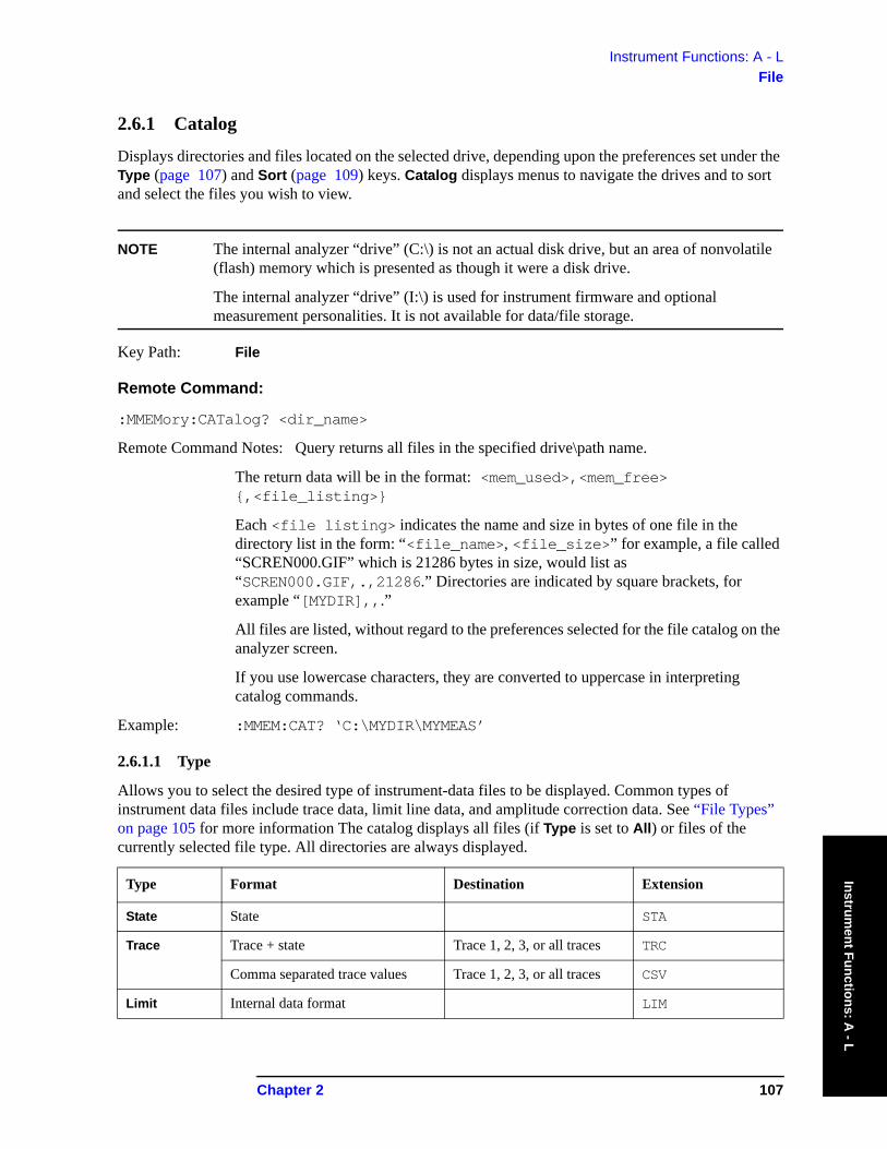
Instrument Functions: A - LFile
Instrument Functions: A
- L
2.6.1 Catalog
Displays directories and files located on the selected drive, depending upon the preferences set under the Type (page 107) and Sort (page 109) keys. Catalog displays menus to navigate the drives and to sort and select the files you wish to view.
NOTE The internal analyzer “drive” (C:\) is not an actual disk drive, but an area of nonvolatile (flash) memory which is presented as though it were a disk drive.
The internal analyzer “drive” (I:\) is used for instrument firmware and optional measurement personalities. It is not available for data/file storage.
Key Path: File
Remote Command:
:MMEMory:CATalog? <dir_name>
Remote Command Notes: Query returns all files in the specified drive\path name.
The return data will be in the format: <mem_used>,<mem_free> {,<file_listing>}
Each <file listing> indicates the name and size in bytes of one file in the directory list in the form: “<file_name>, <file_size>” for example, a file called “SCREN000.GIF” which is 21286 bytes in size, would list as “SCREN000.GIF,.,21286.” Directories are indicated by square brackets, for example “[MYDIR],,.”
All files are listed, without regard to the preferences selected for the file catalog on the analyzer screen.
If you use lowercase characters, they are converted to uppercase in interpreting catalog commands.
Example: :MMEM:CAT? ‘C:\MYDIR\MYMEAS’
2.6.1.1 Type
Allows you to select the desired type of instrument-data files to be displayed. Common types of instrument data files include trace data, limit line data, and amplitude correction data. See “File Types” on page 105 for more information The catalog displays all files (if Type is set to All) or files of the currently selected file type. All directories are always displayed.
Type Format Destination Extension
State State STA
Trace Trace + state Trace 1, 2, 3, or all traces TRC
Comma separated trace values Trace 1, 2, 3, or all traces CSV
Limit Internal data format LIM
Chapter 2 107

Instrument Functions: A - LFile
Inst
rum
ent F
unct
ions
: A -
L
Key Path: File, Catalog
State Saved: Type is not saved in the instrument state
Factory Preset: Type survives Factory Preset and *RST, but is set to State at power on.
Remote Command:
There is no remote command for this key.
2.6.1.1.1 All
Displays all files located in the selected directory. If selected, it applies to Catalog, Delete, Copy, and Rename.
Key Path: File, Catalog, Type
2.6.1.1.2 State
Displays all state files (STA) in the selected directory. State files contain most instrument settings. If selected, it applies to all File functions.
Key Path: File, Catalog, Type
2.6.1.1.3 Trace
Displays all trace files (TRC and CSV) in the selected directory. If selected, it applies to all File functions.
Key Path: File, Catalog, Type
2.6.1.1.4 Limits
Displays all limits files (LIM) in the selected directory.
Key Path: File, Catalog, Type
Screen Bitmap GIF
Reverse bitmap GIF
Corrections Internal data format ANT, CBL, OTH, and AMP
Measurement Results
Comma separated values CSV
Type Format Destination Extension
108 Chapter 2

Instrument Functions: A - LFile
Instrument Functions: A
- L
2.6.1.1.5 Screen
Displays all screen files (GIF) in the selected directory.
To save a screen file, press File, Save, Type, Screen. Then press the front-panel Return key to return to the measurement display. You can then press the front-panel Save key to save the current image.
Key Path: File, Catalog, Type
2.6.1.1.6 Corrections
Displays all correction files (ANT, CBL, OTH, and AMP) in the selected directory.
Key Path: File, Catalog, Type
2.6.1.2 Sort
Displays the Sort menu keys that enable you to view your saved files according to a selected file attribute.The selections include, By Date, By Name, By Extension, By Size, and Order. Order (Up) sorts files in ascending order (for example, A,B,C). Order (Down) sorts files in descending order (for example, C,B,A).
The Sort setting applies to all of the File functions, except Save.
Key Path: File, Catalog
State Saved: The Sort order survives Preset, but is not saved in the instrument state.
Remote Command:
There is no remote command for this key.
2.6.1.2.1 By Date
Sorts and displays the current file catalog by the date of the files.
Key Path: File, Catalog, Sort
2.6.1.2.2 By Name
Sorts and displays the current file catalog in alphabetical order of the name of the files.
Key Path: File, Catalog, Sort
Chapter 2 109
Instrument Functions: A - LFile
Inst
rum
ent F
unct
ions
: A -
L
2.6.1.2.3 By Extension
Sorts and displays the current file catalog, in alphabetical order, by the file extension of the file names (for example: .TRC, .STA).
Key Path: File, Catalog, Sort
2.6.1.2.4 By Size
Sorts and displays the current file catalog by the size of the files.
Key Path: File, Catalog, Sort
2.6.1.2.5 Order
Changes the order of the display of the current file catalog. Up sorts the files in ascending order (A to Z, 1 to 9), while Down sorts in descending order (Z to A, 9 to 1).
Key Path: File, Catalog, Sort
2.6.1.3 Dir Up
Moves up one subdirectory level within a directory. If your position is in the top level of the drive already, it moves up to the drive level and the current drive is highlighted (A: or C:).
Key Path: File, Catalog
2.6.1.4 Dir Select
Selects the drive or directory that is highlighted on the display. You can use the up and down arrows to select and highlight the desired drive or directory. If the top entry in the catalog has a “. .” indication, you are in a subdirectory, and this key acts the same as the Dir Up key. When you are at the top directory level, this key moves up to the drive level.
Key Path: File, Catalog
110 Chapter 2
Instrument Functions: A - LFile
Instrument Functions: A
- L
2.6.2 Save
Displays menu keys that enable you to save files to the floppy (A:) or internal (C:) drive.
The menus allow you to fill in data-entry fields for file name, type, format, source, and path (directory). Some fields may be blank depending on file type.
The catalog list box is active and can be used for selecting the directory in which to save the file. Saved files that match the current Type and Format are shown. The Sort Order is always Down, By Date.
NOTE Never remove the diskette during a save operation. To do so could corrupt all data on the diskette.
Saving directly to floppy drive A:\ can be slow. Try saving first to internal drive C:\ and then transfer the file to the floppy drive.
NOTE Many errors can be generated by a bad Save operation. For this reason, if an ‘Unable to Save file’ message is seen, you should check the error queue (System, Show Errors) for the source of the error.
NOTE You can press the front-panel Save key to immediately save a file using an automatically generated file name. The current Save parameters will be used, as though Save Now had been pressed.
NOTE If saving a Screen, the screen saved is the screen that was displayed before pressing File. For this reason, the screens seen while in the File menus cannot be saved.
Key Path: File
Factory Preset: State is the default file type at power on.
Chapter 2 111
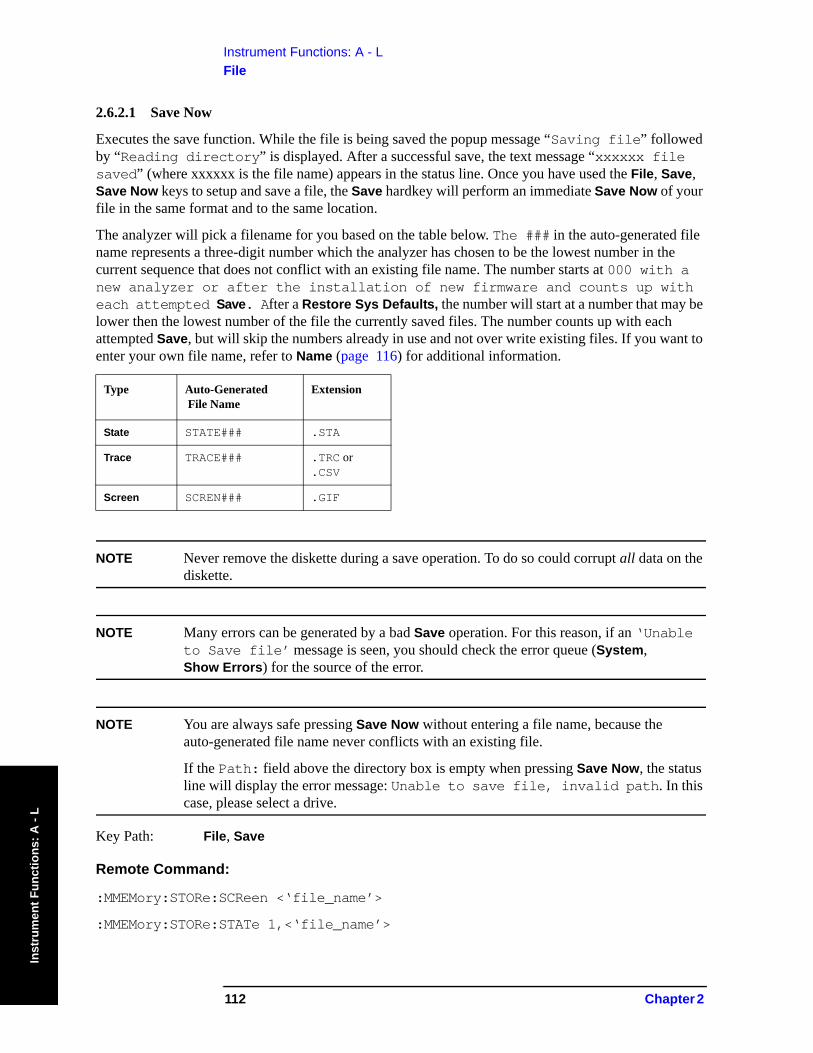
Instrument Functions: A - LFile
Inst
rum
ent F
unct
ions
: A -
L
2.6.2.1 Save Now
Executes the save function. While the file is being saved the popup message “Saving file” followed by “Reading directory” is displayed. After a successful save, the text message “xxxxxx file saved” (where xxxxxx is the file name) appears in the status line. Once you have used the File, Save, Save Now keys to setup and save a file, the Save hardkey will perform an immediate Save Now of your file in the same format and to the same location.
The analyzer will pick a filename for you based on the table below. The ### in the auto-generated file name represents a three-digit number which the analyzer has chosen to be the lowest number in the current sequence that does not conflict with an existing file name. The number starts at 000 with a new analyzer or after the installation of new firmware and counts up with each attempted Save. After a Restore Sys Defaults, the number will start at a number that may be lower then the lowest number of the file the currently saved files. The number counts up with each attempted Save, but will skip the numbers already in use and not over write existing files. If you want to enter your own file name, refer to Name (page 116) for additional information.
NOTE Never remove the diskette during a save operation. To do so could corrupt all data on the diskette.
NOTE Many errors can be generated by a bad Save operation. For this reason, if an ‘Unable to Save file’ message is seen, you should check the error queue (System, Show Errors) for the source of the error.
NOTE You are always safe pressing Save Now without entering a file name, because the auto-generated file name never conflicts with an existing file.
If the Path: field above the directory box is empty when pressing Save Now, the status line will display the error message: Unable to save file, invalid path. In this case, please select a drive.
Key Path: File, Save
Remote Command:
:MMEMory:STORe:SCReen <‘file_name’>
:MMEMory:STORe:STATe 1,<‘file_name’>
Type Auto-Generated File Name
Extension
State STATE### .STA
Trace TRACE### .TRC or .CSV
Screen SCREN### .GIF
112 Chapter 2
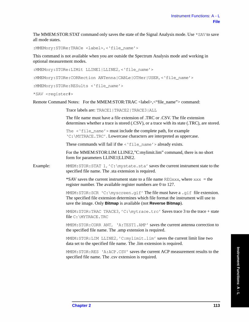
Instrument Functions: A - LFile
Instrument Functions: A
- L
The MMEM:STOR:STAT command only saves the state of the Signal Analysis mode. Use *SAV to save all mode states.
:MMEMory:STORe:TRACe <label>,<‘file_name’>
This command is not available when you are outside the Spectrum Analysis mode and working in optional measurement modes.
:MMEMory:STORe:LIMit LLINE1|LLINE2,<‘file_name’>
:MMEMory:STORe:CORRection ANTenna|CABLe|OTHer|USER,<‘file_name’>
:MMEMory:STORe:RESults <‘file_name’>
*SAV <register#>
Remote Command Notes: For the MMEM:STOR:TRAC <label>,<“file_name”> command:
Trace labels are: TRACE1|TRACE2|TRACE3|ALL
The file name must have a file extension of .TRC or .CSV. The file extension determines whether a trace is stored (.CSV), or a trace with its state (.TRC), are stored.
The <‘file_name’> must include the complete path, for example ‘C:\MYTRACE.TRC’. Lowercase characters are interpreted as uppercase.
These commands will fail if the <‘file_name’> already exists.
For the MMEM:STOR:LIM LLINE2,”C:mylimit.lim” command, there is no short form for parameters LLINE1|LLINE2.
Example: MMEM:STOR:STAT 1,’C:\mystate.sta’ saves the current instrument state to the specified file name. The .sta extension is required.
*SAV saves the current instrument state to a file name REGxxx, where xxx = the register number. The available register numbers are 0 to 127.
MMEM:STOR:SCR ‘C:\myscreen.gif’ The file must have a .gif file extension. The specified file extension determines which file format the instrument will use to save the image. Only Bitmap is available (not Reverse Bitmap).
MMEM:STOR:TRAC TRACE3,’C:\mytrace.trc’ Saves trace 3 to the trace + state file C:\MYTRACE.TRC
MMEM:STOR:CORR ANT, ‘A:TEST1.AMP’ saves the current antenna correction to the specified file name. The .amp extension is required.
MMEM:STOR:LIM LLINE2,’C:mylimit.lim’ saves the current limit line two data set to the specified file name. The .lim extension is required.
MMEM:STOR:RES ‘A:ACP.CSV’ saves the current ACP measurement results to the specified file name. The .csv extension is required.
Chapter 2 113
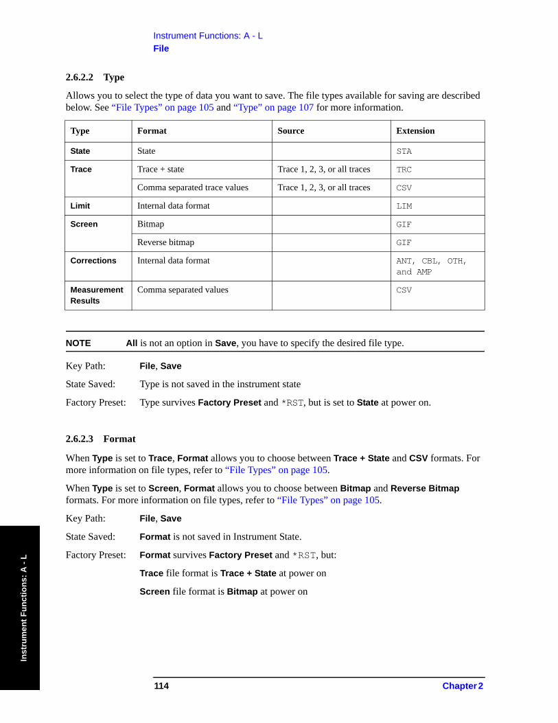
Instrument Functions: A - LFile
Inst
rum
ent F
unct
ions
: A -
L
2.6.2.2 Type
Allows you to select the type of data you want to save. The file types available for saving are described below. See “File Types” on page 105 and “Type” on page 107 for more information.
NOTE All is not an option in Save, you have to specify the desired file type.
Key Path: File, Save
State Saved: Type is not saved in the instrument state
Factory Preset: Type survives Factory Preset and *RST, but is set to State at power on.
2.6.2.3 Format
When Type is set to Trace, Format allows you to choose between Trace + State and CSV formats. For more information on file types, refer to “File Types” on page 105.
When Type is set to Screen, Format allows you to choose between Bitmap and Reverse Bitmap formats. For more information on file types, refer to “File Types” on page 105.
Key Path: File, Save
State Saved: Format is not saved in Instrument State.
Factory Preset: Format survives Factory Preset and *RST, but:
Trace file format is Trace + State at power on
Screen file format is Bitmap at power on
Type Format Source Extension
State State STA
Trace Trace + state Trace 1, 2, 3, or all traces TRC
Comma separated trace values Trace 1, 2, 3, or all traces CSV
Limit Internal data format LIM
Screen Bitmap GIF
Reverse bitmap GIF
Corrections Internal data format ANT, CBL, OTH, and AMP
Measurement Results
Comma separated values CSV
114 Chapter 2
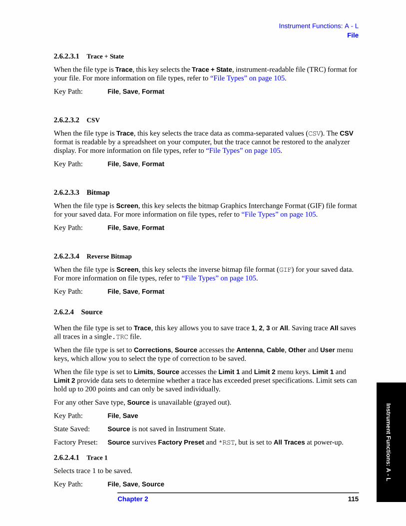
Instrument Functions: A - LFile
Instrument Functions: A
- L
2.6.2.3.1 Trace + State
When the file type is Trace, this key selects the Trace + State, instrument-readable file (TRC) format for your file. For more information on file types, refer to “File Types” on page 105.
Key Path: File, Save, Format
2.6.2.3.2 CSV
When the file type is Trace, this key selects the trace data as comma-separated values (CSV). The CSV format is readable by a spreadsheet on your computer, but the trace cannot be restored to the analyzer display. For more information on file types, refer to “File Types” on page 105.
Key Path: File, Save, Format
2.6.2.3.3 Bitmap
When the file type is Screen, this key selects the bitmap Graphics Interchange Format (GIF) file format for your saved data. For more information on file types, refer to “File Types” on page 105.
Key Path: File, Save, Format
2.6.2.3.4 Reverse Bitmap
When the file type is Screen, this key selects the inverse bitmap file format (GIF) for your saved data. For more information on file types, refer to “File Types” on page 105.
Key Path: File, Save, Format
2.6.2.4 Source
When the file type is set to Trace, this key allows you to save trace 1, 2, 3 or All. Saving trace All saves all traces in a single.TRC file.
When the file type is set to Corrections, Source accesses the Antenna, Cable, Other and User menu keys, which allow you to select the type of correction to be saved.
When the file type is set to Limits, Source accesses the Limit 1 and Limit 2 menu keys. Limit 1 and Limit 2 provide data sets to determine whether a trace has exceeded preset specifications. Limit sets can hold up to 200 points and can only be saved individually.
For any other Save type, Source is unavailable (grayed out).
Key Path: File, Save
State Saved: Source is not saved in Instrument State.
Factory Preset: Source survives Factory Preset and *RST, but is set to All Traces at power-up.
2.6.2.4.1 Trace 1
Selects trace 1 to be saved.
Key Path: File, Save, Source
Chapter 2 115
Instrument Functions: A - LFile
Inst
rum
ent F
unct
ions
: A -
L
2.6.2.4.2 Trace 2
Selects trace 2 to be saved.
Key Path: File, Save, Source
2.6.2.4.3 Trace 3
Selects trace 3 to be saved.
Key Path: File, Save, Source
2.6.2.4.4 All Traces
Selects all the traces to be saved.
Key Path: File, Save, Source
2.6.2.5 Name
Displays the Alpha Editor and enables you to enter a filename. The numeric keypad can also be used while entering file names. Press Enter or Return to complete the name entry.
NOTE Only capital letters (A-Z) and digits (0-9) may appear in file names (8 characters, maximum). Additionally, file names include a 3 digit extension which is automatically set by the instrument depending on the file type and format.
Key Path: File, Save
Remote Command:
The file name is entered as part of the directory path name that is sent with the SCPI command. See “Save Now” on page 112.
2.6.2.6 Dir Up
Moves up one subdirectory level within a directory. If your position is in the top level of the drive already, it moves up to the drive level and the current drive is highlighted (A: or C:).
Key Path: File, Save
Remote Command:
The directory is entered as part of the directory path name that is sent with the SCPI command. See “Save Now” on page 112.
116 Chapter 2
Instrument Functions: A - LFile
Instrument Functions: A
- L
2.6.2.7 Dir Select
Displays the highlighted directory. See “Dir Select” on page 110 for more information.
Key Path: File, Save
Remote Command:
The directory is entered as part of the directory path name that is sent with the SCPI command. See “Save Now” on page 112.
2.6.3 Load
Displays the menu key that enables you to load instrument-data files from the selected drive and directory back into the instrument. This function displays the file list box, which shows the data-entry fields for the file name, type, destination, and path.
The catalog list box is active and can be used for selecting the file information in the data-entry fields. Only loadable files that match the current type are shown. Placing the cursor on a file name causes it to be loaded into the file name field.
Key Path: File
2.6.3.1 Load Now
Loads the currently selected file. Displayed settings include name, type, destination, and path. While the file is being loaded a popup message is displayed “Loading file.” After a successful load, the text message “xxxxxx file loaded” (where xxxxxx is the file name) appears in the status line. When traces are loaded they always load in View mode.
Traces save in TRC format can be loaded individually or as a group. When a trace is loaded, the state that existed when that trace was saved is loaded along with the trace. Also, the loaded trace(s) is/are placed in view mode.
NOTE To compare two saved traces from different saves, place traces in view mode before saving them. This prevents the trace from being rewritten based on a state change from subsequent loads.
Key Path: File, Load
Chapter 2 117
Instrument Functions: A - LFile
Inst
rum
ent F
unct
ions
: A -
L
Remote Command:
:MMEMory:LOAD:STATe 1,<‘file_name’> loads the specified state file into the current active state of the instrument.
The MMEM:LOAD:STAT command only saves the state of the Signal Analysis mode. Use *RCL to load all mode states. *RCL <register#> loads the state from the specified internal register into the current active state of the instrument. The available register numbers are 0 to 127.
:MMEMory:LOAD:TRACe <label>,<‘file_name’>
:MMEMory:LOAD:CORRection ANTenna|CABLe|OTHer|USER,<‘file_name’>
:MMEMory:LOAD:LIMit LLINE1|LLINE2,<‘file_name’>
Remote Command Notes: For the MMEM:LOAD:TRAC <‘file_name’> command, <‘file_name’> must include the following:
• Complete path• A file extension of TRC• Use all uppercase letters.• Trace labels are: TRACE1|TRACE2|TRACE3
For the MMEM:LOAD:STAT 1 command:
• If the firmware revision of the state being loaded is newer than the firmware revision of the instrument, no state is recalled and an error is reported.
• If the firmware revision of the state being loaded is the same as the firmware revision of the instrument, all settings of the state will be loaded.
• If the firmware revision of the state being loaded is older than the firmware revision of the instrument, the instrument will only load the older settings of the state.
Example: MMEM:LOAD:STAT 1,’C:MYSTATE.STA’ loads the state file C:\MYSTATE.STA.
MMEM:LOAD:TRAC,’C:MYTRACE.TRC’ loads the trace in file C:\MYTRACE.TRC into trace 3.
118 Chapter 2
Instrument Functions: A - LFile
Instrument Functions: A
- L
2.6.3.2 Type
Enables you to select the type of file you want to load. See “File Types” on page 105. and “Type” on page 107 for more information.
The file types available for loading are described in the following table:
NOTE All is not a file type option in Load. You have to specify the desired file type.
Key Path: File, Load
2.6.3.3 Sort
Allows you to view saved files according to a selected file attribute. See “Sort” on page 109 for more information.
Key Path: File, Load
2.6.3.4 Destination
When Type is set to Trace, Destination allows you to direct your data to Trace 1, Trace 2, or Trace 3 for a single-trace file. If the data is for all three traces (Source was All when they were saved), the data will be returned to the original trace registers, regardless of the Destination setting.
When Type is set to Limits, Destination allows you to direct your data to Limit 1 or Limit 2.
Key Path: File, Load
State Saved: Not saved in Instrument State.
Factory Preset: Trace file format, is All Traces at power on.
Type Format Destination Extension
State State STA
Trace Trace + state Trace 1, 2, 3, or all traces TRC
Comma separated trace values Trace 1, 2, 3, or all traces CSV
Limit Internal data format LIM
Corrections Internal data format ANT, CBL, OTH, and AMP
Chapter 2 119
Instrument Functions: A - LFile
Inst
rum
ent F
unct
ions
: A -
L
2.6.3.4.1 Trace 1
Selects trace 1 for the trace data to be loaded into.
Key Path: File, Load, Destination
State Saved: Not saved in Instrument State.
Factory Preset: Not affected by Preset. Power up and Restore Sys Defaults sets Trace 1.
2.6.3.4.2 Trace 2
Selects trace 2 for the trace data to be loaded into.
Key Path: File, Load, Destination
State Saved: Not saved in Instrument State.
Factory Preset: Not affected by Preset. Power up and Restore Sys Defaults sets Trace 1.
2.6.3.4.3 Trace 3
Selects trace 3 for the trace data to be loaded into.
Key Path: File, Load, Destination
State Saved: Not saved in Instrument State.
Factory Preset: Not affected by Preset. Power up and Restore Sys Defaults sets Trace 1.
2.6.3.5 Dir Up
Moves up one subdirectory level within a directory. If your position is in the top level of the drive already, it moves up to the drive level and the current drive is highlighted (A: or C:).
Key Path: File, Load
State Saved: Not saved in Instrument State.
Factory Preset: Trace file format, is All Traces at power on.
2.6.3.6 Dir Select
Displays the highlighted directory. See “Dir Select” on page 110. for more information.
Key Path: File, Load
State Saved: Not saved in Instrument State.
Factory Preset: Trace file format, is All Traces at power on.
120 Chapter 2
Instrument Functions: A - LFile
Instrument Functions: A
- L
2.6.4 Delete
Displays the Delete menu keys that enable you to delete instrument data files from the selected directory. The catalog list box is active and can be used for selecting file information for the data-entry fields. Only files that match the current type are shown. Placing the cursor on a file name causes it to be loaded into the file name field.
Key Path: File
2.6.4.1 Delete Now
Executes the delete function. After you select the file or directory you want to delete, press Delete Now to perform the delete. While the file is being deleted, the popup message “Deleting file” followed by “Reading directory” are displayed. After a successful deletion, the text message “xxxxxx file deleted” (where xxxxxx is the file name) appears in the status line.
If you select a directory or subdirectory to delete, the following popup message is displayed “WARNING: You are about to delete all of the contents of directory xxxxxx. Press Delete Now again to proceed or any other key to abort.” (xxxxxx is the full path and directory name).
To quickly delete all of the files in a directory, select the file at the top of the list and press Delete Now repeatedly until all the files are deleted.
Key Path: File, Delete
Remote Command:
:MMEMory:DELete <‘file_name’> deletes a file.
:MMEMory:RDIRectory <‘directory_name’> deletes a directory.
Remote Command Notes: If <‘file_name’> does not exist, a “File Name Error” occurs.
<‘file_name’> and <‘directory_name’> must include the complete path. Lowercase characters are read as uppercase.
Example: MMEM:DEL ‘C:\destinat.trc’ removes the file C:\DESTINAT.TRC.
MMEM:RDIR ‘C:\myDir’ removes directory C:\MYDIR and all files and subdirectories within that directory.
2.6.4.2 Type
Allows you to select the type of file you want to delete. See “File Types” on page 105. and “Type” on page 107 for more information.
Common types of instrument data files include trace data, limit line data, and amplitude correction data. The catalog displays all files, if Type is set to All or files of the currently selected file type. All directories are always displayed.
Key Path: File, Delete
Chapter 2 121
Instrument Functions: A - LFile
Inst
rum
ent F
unct
ions
: A -
L
2.6.4.3 Sort
Allows you to view your saved files according to a selected file attribute. See “Sort” on page 109. for more information.
Key Path: File, Delete
2.6.4.4 Dir Up
Moves up one subdirectory level within a directory. If your position is in the top level of the drive already, it moves up to the drive level and the current drive is highlighted (A: or C:).
Key Path: File, Delete
2.6.4.5 Dir Select
Displays the highlighted directory. See “Dir Select” on page 110. for more information.
Key Path: File, Delete
2.6.5 Copy
Displays the functions to copy instrument data files in the selected directory to the directory and file name that you choose. This key also displays a catalog of the files that are currently saved in the selected directory and data-entry fields for the following: file name, type, and path location.
Key Path: File
2.6.5.1 Copy Now
Executes the copy function, coping data files from one directory to another on one or more mass storage devices, using the currently displayed file settings. While the file is being copied, the “Copying file” followed by “Reading directory” popup message is displayed. After a successful copy, the green text message “xxxxxx file copied” (where xxxxxx is the file name) appears in the status line. If a copy is being done for a file that already exists in the “To” directory, the text message “File already exists” appears in the status line.
Key Path: File, Copy
Remote Command:
:MMEMory:COPY <‘file_name1’>,<‘file_name2’>
Remote Command Notes: The file names must include the complete file paths. Lowercase characters are read as uppercase.
The original file is <“file_name1”>, and the new copy of the file is <“file_name2”>.
Example: :MMEM:COPY ‘C:\oldname.sta’,’A:\newname.sta’ copies C:\OLDNAME.STA to A:\NEWNAME.STA.
2.6.5.2 Type
Enables you to select the type of file you want to copy. See “File Types” on page 105. and “Type” on page 107 for more information. If Type is set to All, the catalog displays all files, otherwise the files of
122 Chapter 2

Instrument Functions: A - LFile
Instrument Functions: A
- L
the currently selected file type are displayed. All directories are always displayed.
Key Path: File, Copy
2.6.5.3 Sort
Allows you to view your saved files according to a selected file attribute. See “Sort” on page 109. for more information.
Key Path: File, Copy
2.6.5.4 Dir From/To
Allows you to select the source and destination directories for your copy on one or more drives. When you press Dir From/To, it toggles between the two displayed directory list windows. Allowing you to define the “From” and “To” locations for copying.
Key Path: File, Copy
State Saved: Powers up with C:\ as both the “From” and “To” drives. Not saved in state. Survives Factory Preset.
2.6.5.5 Dir Up
Moves up one subdirectory level within a directory. If your position is in the top level of the drive already, it moves up to the drive level and the current drive is highlighted (A: or C:).
Key Path: File, Copy
Type Format Extension
State State STA
Trace Trace + state TRC
Comma separated trace values CSV
Limit Internal data format LIM
Screen Bitmap GIF
Reverse bitmap GIF
Corrections Internal data format ANT, CBL, OTH, and
AMP
Measurement Results
Comma separated values CSV
Chapter 2 123
Instrument Functions: A - LFile
Inst
rum
ent F
unct
ions
: A -
L
2.6.5.6 Dir Select
Displays the highlighted directory. See “Dir Select” on page 110. for more information.
Key Path: File, Copy
2.6.6 Rename
Allows you to rename a file. The catalog list box is active and can be used for selecting both the path and a file name. Only loadable files that match the current type are shown. Placing the cursor on a file name causes it to be loaded into the file name field.
Key Path: File
2.6.6.1 Rename Now
Executes the rename function. When the rename is complete, the message XXXXXX file renamed to YYYYYY (where XXXXXX and YYYYYY are the filenames) will appear in the status line on your display. If you try to rename a file with a name that already exists, the text message (File already exists) appears in the status line. Placing the cursor on a file name causes it to be loaded into the file name field.
Key Path: File, Rename
Remote Command:
:MMEMory:MOVE <‘file_name1’>,<‘file_name2’>
Remote Command Notes: <‘file_name1’> must include the complete path, and the case must match that of the file to be renamed. <‘file_name2’> must contain the complete path of the destination, and the case of any directories in the path must match those of the directories in the destination path. The case of the destination file name is always interpreted as uppercase.
You can use this command to move files between directories and drives, even though there is no way to do this from the front panel.
Example: MMEM:MOVE ‘C:\STATE001.STA’,’C:\FREQ.STA’
2.6.6.2 Type
Enables you to select the type of file you want to rename. See “File Types” on page 105. and “Type” on page 107 for more information.
If Type is set to All, the catalog displays all files, otherwise the files of the currently selected file type are displayed. All directories are always displayed.
Type Format Extension
State State STA
Trace Trace + state TRC
Comma separated trace values CSV
Limit Internal data format LIM
124 Chapter 2
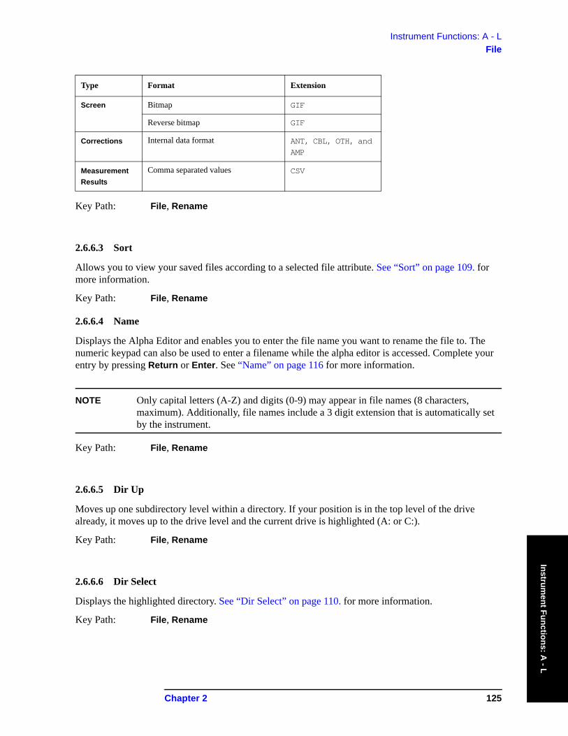
Instrument Functions: A - LFile
Instrument Functions: A
- L
Key Path: File, Rename
2.6.6.3 Sort
Allows you to view your saved files according to a selected file attribute. See “Sort” on page 109. for more information.
Key Path: File, Rename
2.6.6.4 Name
Displays the Alpha Editor and enables you to enter the file name you want to rename the file to. The numeric keypad can also be used to enter a filename while the alpha editor is accessed. Complete your entry by pressing Return or Enter. See “Name” on page 116 for more information.
NOTE Only capital letters (A-Z) and digits (0-9) may appear in file names (8 characters, maximum). Additionally, file names include a 3 digit extension that is automatically set by the instrument.
Key Path: File, Rename
2.6.6.5 Dir Up
Moves up one subdirectory level within a directory. If your position is in the top level of the drive already, it moves up to the drive level and the current drive is highlighted (A: or C:).
Key Path: File, Rename
2.6.6.6 Dir Select
Displays the highlighted directory. See “Dir Select” on page 110. for more information.
Key Path: File, Rename
Screen Bitmap GIF
Reverse bitmap GIF
Corrections Internal data format ANT, CBL, OTH, and
AMP
Measurement Results
Comma separated values CSV
Type Format Extension
Chapter 2 125
Instrument Functions: A - LFile
Inst
rum
ent F
unct
ions
: A -
L
2.6.7 Create Dir
Displays the functions to create a new subdirectory in the currently selected directory.
Key Path: File
2.6.7.1 Create Dir Now
Executes the create a new directory function. While the directory is being created a popup message is displayed “Creating directory” followed by “Reading directory.” After the successful creation of a directory, the text message “Directory xxxxxx created” (where xxxxxx is the new directory name) appears in the status line. If the creation of a new directory is being performed for a directory name that already exists, the text message “Directory already exists” appears in the status line.
Key Path: File, Create Dir
Remote Command:
:MMEMory:MDIRectory <‘dir_name’>
Remote Command Notes: <‘dir_name’> must contain the complete path for the new directory. Lowercase characters are interpreted as uppercase.
Example: MMEM:MDIR ‘C:\myDir’ creates directory MYDIR on the C:\ drive.
2.6.7.2 Name
Displays the Alpha Editor and enables you to enter a directory name. The numeric keypad can also be used to enter a directory name while the alpha editor is accessed. To complete the entry, press Return or Enter.
NOTE Only capital letters (A-Z) and digits (0-9) may appear in directory names (8 characters, maximum).
Key Path: File, Create Dir
2.6.7.3 Dir Up
Moves up one subdirectory level within a directory. If your position is in the top level of the drive already, it moves up to the drive level and the current drive is highlighted (A: or C:).
Key Path: File, Create Dir
2.6.7.4 Dir Select
Displays the highlighted directory. See “Dir Select” on page 110. for more information.
Key Path: File, Create Dir
126 Chapter 2
Instrument Functions: A - LFile
Instrument Functions: A
- L
2.6.8 Delete All
Deletes all the files on a diskette; any information on the disk will be destroyed.
Key Type: Branch
Key Notes: This key displays the file manager display form which includes data entry fields for the new drive name and path.
There is another definition of Format key that defines the format (file type) of you data that you want to save.
Remote Command:
There is no remote command for this key.
2.6.8.1 Delete All Now
Executes the Delete All function. After pressing Delete All, the following message will appear on the display: WARNING: You are about to destroy ALL data on volume A: Press Delete All again to proceed or any other key to abort. While deleting, a popup message is displayed “Deleting All.” After a successful diskette file deletion, the green text message “Volume A: delete complete”, appears in the status line.
Key Path: File, Delete All
Remote Command:
There is no remote command for this key.
2.6.9 Query Trace Data (Remote Command Only)
This command queries trace data from the specified trace. The data format is set by the command :FORMat [:TRACe][:DATA]. When ASCII format is selected, the data is comma-separated ASCII values. Real or Integer format uses a definite length block of data.
The number of trace points returned is set by [:SENSE]:SWE:POIN (from 101 to 8192).
Remote Command:
:TRACe[:DATA]? TRACE1|TRACE2|TRACE3|LLINE1|LLINE2
Remote Command Notes: Commands :MMEM:STOR:TRAC and :MMEM:LOAD:TRAC are used to transfer trace data to, or from, the internal hard drive or floppy drive of the instrument.
The query returns the current values of the designated trace. The data is terminated with <NL><END> (for GPIB that is newline, or linefeed, followed by EOI set true.)
Example: TRAC:DATA? TRACE1
2.6.10 Move Data to a File (Remote Command Only)
This command loads a block of data in the format <definite_length_block> into the instrument memory
Chapter 2 127
Instrument Functions: A - LFile
Inst
rum
ent F
unct
ions
: A -
L
location <‘file_name’>. The query form of the command returns the contents of the file identified by <‘file_name’>, in the format of a definite length block of data. The query can be used for copying files out of the analyzer over the remote bus.
A definite length block of data starts with an ASCII header that begins with # and indicates how many additional data points are following in the block. If the header is #512320:
• The first digit in the header (5) tells you how many additional digits/bytes there are in the header.
• The 12320 means 12,320 data bytes follow the header.
• Divide this number of bytes by your selected data format bytes/point, either 8 (for real 64), or 4 (for real 32). In this example, if you are using real 64 then there are 1540 points in the block.
Remote Command:
:MMEMory:DATA <‘file_name’>,<definite_length_block>
:MMEMory:DATA? <‘file_name’>
Example: MMEM:DATA ‘C:\DEST.TXT’,#14abcd Loads the data “abcd” into C:\DEST.TXT.
MMEM:DATA? ‘C:\SCREN001.GIF’ Initiates a transfer of data from file C:\SCREN001.GIF.
2.6.11 Set Data Byte Order (Remote Command Only)
This command selects the binary data byte order for data transfer. It controls whether binary data is transferred in normal or swapped mode. Normal mode is when the byte sequence begins with the most significant byte (MSB) first, and ends with the least significant byte (LSB) last in the sequence: 1|2|3|4. Swapped mode is when the byte sequence begins with the LSB first, and ends with the MSB last in the sequence: 4|3|2|1.
State Saved: Survives Preset but not power cycle. Not saved in Instrument State.
Factory Preset: Normal
Remote Command:
:FORMat:BORDer NORMal|SWAPped
:FORMat:BORDer?
Example: FORM:BORD SWAP
2.6.12 Format Numeric Data (Remote Command Only)
This command changes the format of the data. It specifies the format used for trace data during data transfer across any remote port. REAL and ASCII formats will format trace data in the current amplitude units. The format of state data cannot be changed. It is always in a machine readable format only.
NOTE One-button measurement functions only support Binary Real 32, Binary Real 64, and ASCII data formats.
128 Chapter 2
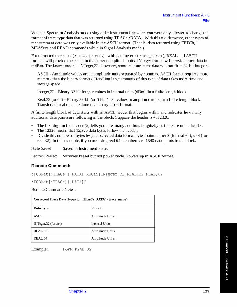
Instrument Functions: A - LFile
Instrument Functions: A
- L
When in Spectrum Analysis mode using older instrument firmware, you were only allowed to change the format of trace type data that was returned using TRACe[:DATA]. With this old firmware, other types of measurement data was only available in the ASCII format. (That is, data returned using FETCh, MEASure and READ commands while in Signal Analysis mode.)
For corrected trace data (:TRACe[:DATA] with parameter <trace_name>), REAL and ASCII formats will provide trace data in the current amplitude units. INTeger format will provide trace data in mdBm. The fastest mode is INTeger,32. However, some measurement data will not fit in 32-bit integers.
ASCII - Amplitude values are in amplitude units separated by commas. ASCII format requires more memory than the binary formats. Handling large amounts of this type of data takes more time and storage space.
Integer,32 - Binary 32-bit integer values in internal units (dBm), in a finite length block.
Real,32 (or 64) - Binary 32-bit (or 64-bit) real values in amplitude units, in a finite length block. Transfers of real data are done in a binary block format.
A finite length block of data starts with an ASCII header that begins with # and indicates how many additional data points are following in the block. Suppose the header is #512320:
• The first digit in the header (5) tells you how many additional digits/bytes there are in the header.• The 12320 means that 12,320 data bytes follow the header.• Divide this number of bytes by your selected data format bytes/point, either 8 (for real 64), or 4 (for
real 32). In this example, if you are using real 64 then there are 1540 data points in the block.
State Saved: Saved in Instrument State.
Factory Preset: Survives Preset but not power cycle. Powers up in ASCII format.
Remote Command:
:FORMat[:TRACe][:DATA] ASCii|INTeger,32|REAL,32|REAL,64
:FORMat[:TRACe][:DATA]?
Remote Command Notes:
Example: FORM REAL,32
Corrected Trace Data Types for :TRACe:DATA?<trace_name>
Data Type Result
ASCii Amplitude Units
INTeger,32 (fastest) Internal Units
REAL,32 Amplitude Units
REAL,64 Amplitude Units
Chapter 2 129

Instrument Functions: A - LFile
Inst
rum
ent F
unct
ions
: A -
L
130 Chapter 2
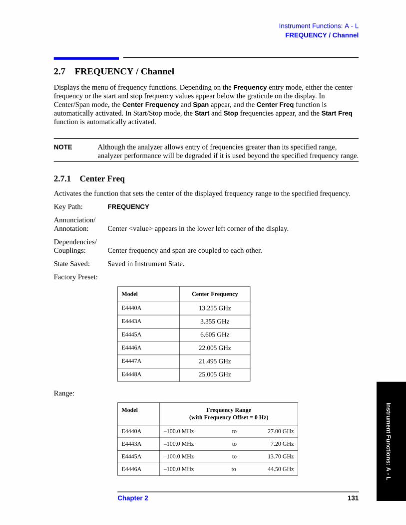
Instrument Functions: A - LFREQUENCY / Channel
Instrument Functions: A
- L
2.7 FREQUENCY / Channel
Displays the menu of frequency functions. Depending on the Frequency entry mode, either the center frequency or the start and stop frequency values appear below the graticule on the display. In Center/Span mode, the Center Frequency and Span appear, and the Center Freq function is automatically activated. In Start/Stop mode, the Start and Stop frequencies appear, and the Start Freq function is automatically activated.
NOTE Although the analyzer allows entry of frequencies greater than its specified range, analyzer performance will be degraded if it is used beyond the specified frequency range.
2.7.1 Center Freq
Activates the function that sets the center of the displayed frequency range to the specified frequency.
Key Path: FREQUENCY
Annunciation/ Annotation: Center <value> appears in the lower left corner of the display.
Dependencies/ Couplings: Center frequency and span are coupled to each other.
State Saved: Saved in Instrument State.
Factory Preset:
Range:
Model Center Frequency
E4440A 13.255 GHz
E4443A 3.355 GHz
E4445A 6.605 GHz
E4446A 22.005 GHz
E4447A 21.495 GHz
E4448A 25.005 GHz
Model Frequency Range(with Frequency Offset = 0 Hz)
E4440A –100.0 MHz to 27.00 GHz
E4443A –100.0 MHz to 7.20 GHz
E4445A –100.0 MHz to 13.70 GHz
E4446A –100.0 MHz to 44.50 GHz
Chapter 2 131

Instrument Functions: A - LFREQUENCY / Channel
Inst
rum
ent F
unct
ions
: A -
L
Remote Command:
[:SENSe]:FREQuency:CENTer <frequency>|UP|DOWN
[:SENSe]:FREQuency:CENTer?
Example: FREQ:CENT 5 GHZ sets the center frequency to 5 GHz
FREQ:CENT UP changes the center frequency to 5.1 GHz if you use FREQ:CENT:STEP 100 MHz to set the center frequency step size to 100 MHz
FREQ:CENT?
2.7.2 Start Freq
Sets the frequency at the left side of the graticule and sets the frequency entry mode to Start/Stop. When the Start/Stop Frequency entry mode is activated, the start and stop frequency values are displayed below the graticule in place of center frequency and span. The left and right sides of the graticule correspond to the start and stop frequencies.
When Start Freq reaches the upper frequency limit, the stop frequency is set to the highest available frequency and the start frequency is changed to be less then the stop frequency by the minimum span (10 Hz). Center Freq will be updated to the stop frequency minus one-half of the span, or to the stop frequency minus 5 Hz, and Res BW and VBW will be set to 1 Hz.
Key Path: FREQUENCY
State Saved: Saved in Instrument State
Factory Preset: 10 MHz
Range:
Remote Command:
[:SENSe]:FREQuency:STARt <freq>
E4447A –100.0 MHz to 43.48 GHz
E4448A –100.0 MHz to 51.00 GHz
Model Frequency Range
E4440A –100.0000000 MHz to 26.99999999 GHz
E4443A –100.0000000 MHz to 7.19999999 GHz
E4445A –100.0000000 MHz to 13.69999999 GHz
E4446A –100.0000000 MHz to 44.49999999 GHz
E4447A –100.0000000 MHz to 43.47999999 GHz
E4448A –100.0000000 MHz to 50.99999999 GHz
Model Frequency Range(with Frequency Offset = 0 Hz)
132 Chapter 2
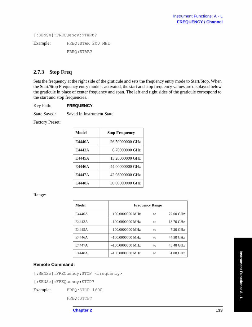
Instrument Functions: A - LFREQUENCY / Channel
Instrument Functions: A
- L
[:SENSe]:FREQuency:STARt?
Example: FREQ:STAR 200 MHz
FREQ:STAR?
2.7.3 Stop Freq
Sets the frequency at the right side of the graticule and sets the frequency entry mode to Start/Stop. When the Start/Stop Frequency entry mode is activated, the start and stop frequency values are displayed below the graticule in place of center frequency and span. The left and right sides of the graticule correspond to the start and stop frequencies.
Key Path: FREQUENCY
State Saved: Saved in Instrument State
Factory Preset:
Range:
Remote Command:
[:SENSe]:FREQuency:STOP <frequency>
[:SENSe]:FREQuency:STOP?
Example: FREQ:STOP 1600
FREQ:STOP?
Model Stop Frequency
E4440A 26.50000000 GHz
E4443A 6.70000000 GHz
E4445A 13.20000000 GHz
E4446A 44.00000000 GHz
E4447A 42.98000000 GHz
E4448A 50.00000000 GHz
Model Frequency Range
E4440A –100.0000000 MHz to 27.00 GHz
E4443A –100.0000000 MHz to 13.70 GHz
E4445A –100.0000000 MHz to 7.20 GHz
E4446A –100.0000000 MHz to 44.50 GHz
E4447A –100.0000000 MHz to 43.48 GHz
E4448A –100.0000000 MHz to 51.00 GHz
Chapter 2 133
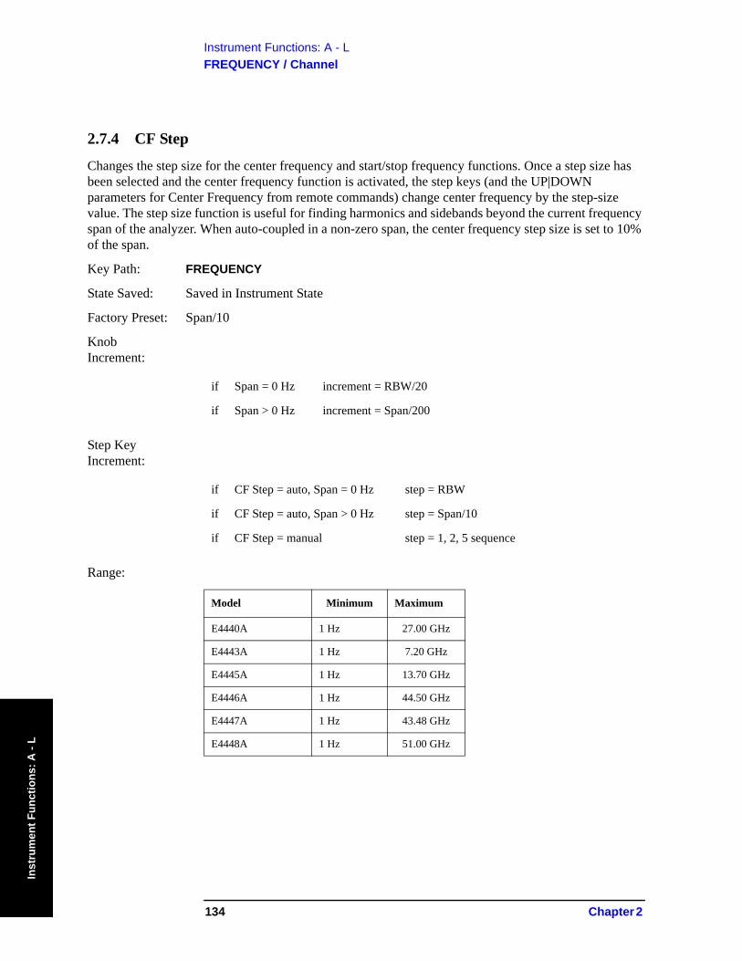
Instrument Functions: A - LFREQUENCY / Channel
Inst
rum
ent F
unct
ions
: A -
L
2.7.4 CF Step
Changes the step size for the center frequency and start/stop frequency functions. Once a step size has been selected and the center frequency function is activated, the step keys (and the UP|DOWN parameters for Center Frequency from remote commands) change center frequency by the step-size value. The step size function is useful for finding harmonics and sidebands beyond the current frequency span of the analyzer. When auto-coupled in a non-zero span, the center frequency step size is set to 10% of the span.
Key Path: FREQUENCY
State Saved: Saved in Instrument State
Factory Preset: Span/10
Knob Increment:
Step Key Increment:
Range:
if Span = 0 Hz increment = RBW/20
if Span > 0 Hz increment = Span/200
if CF Step = auto, Span = 0 Hz step = RBW
if CF Step = auto, Span > 0 Hz step = Span/10
if CF Step = manual step = 1, 2, 5 sequence
Model Minimum Maximum
E4440A 1 Hz 27.00 GHz
E4443A 1 Hz 7.20 GHz
E4445A 1 Hz 13.70 GHz
E4446A 1 Hz 44.50 GHz
E4447A 1 Hz 43.48 GHz
E4448A 1 Hz 51.00 GHz
134 Chapter 2
Instrument Functions: A - LFREQUENCY / Channel
Instrument Functions: A
- L
Remote Command:
[:SENSe]:FREQuency:CENTer:STEP[:INCRement] <freq>
[:SENSe]:FREQuency:CENTer:STEP[:INCRement]?
[:SENSe]:FREQuency:CENTer:STEP:AUTO OFF|ON|0|1
[:SENSe]:FREQuency:CENTer:STEP:AUTO?
Example: FREQ:CENT:STEP:AUTO ON
FREQ:CENT:STEP 500 MHz
FREQ:CENT UP increases the current center frequency value by 500 MHz
FREQ:CENT:STEP?
FREQ:CENT:STEP:AUTO?
2.7.5 Freq Offset
Enables you to input a frequency offset value to account for frequency conversions external to the analyzer. This value is added to the display readout of the marker frequency, center frequency, start frequency, stop frequency and all other absolute frequency settings in the analyzer. When a frequency offset is entered, the value appears below the center of the graticule. Offsets may only be entered using the numeric keypad, not the knob or step keys. To eliminate an offset, perform a Factory Preset or set the frequency offset to 0 Hz.
This command does not affect any bandwidths or the settings of relative frequency parameters such as delta markers or span. It does not affect the current hardware settings of the analyzer, but only the displayed frequency values. Offsets are not added to the frequency count readouts. Entering an offset does not affect the trace display.
Key Path: FREQUENCY
State Saved: Saved in Instrument State
Factory Preset: 0 Hz
Range: –500 THz to 500 THz
Remote Command:
[:SENSe]:FREQuency:OFFSet <freq>
[:SENSe]:FREQuency:OFFSet?
Example: FREQ:OFFS 10 MHz
Chapter 2 135
Instrument Functions: A - LFREQUENCY / Channel
Inst
rum
ent F
unct
ions
: A -
L
2.7.6 Signal Track
When a marker is placed on a signal and Signal Track is pressed, the marker will remain on the signal while the analyzer retunes the center frequency to the marker frequency. The analyzer will keep the signal at the center of the display, as long as the amplitude of the signal does not change by more than 3 dB from one sweep to another. If no marker is active, pressing Signal Track to On will activate a marker, perform a peak search, and center the marker on the display.
If the signal is lost, an attempt will be made to find it again and continue tracking. If there are other signals on screen near the same amplitude, one of them may be found instead. Signals near 0 Hz cannot be tracked effectively as they cannot be distinguished from the LO feedthrough, which is excluded by intent from the search algorithm.
When Signal Track is On and the span is reduced, an automatic zoom is performed and the span is reduced in steps so that the signal remains at the center of the display. If the span is zero, signal track cannot be activated.
NOTE This function is intended to track signals with a frequency that is changing (drifting), and an amplitude that is not changing. It keeps tracking if in continuous-sweep mode. If in single-sweep mode, the analyzer only does one center frequency adjustment as necessary.
Signal tracking can also be used with the Δ (delta) pair marker function. This could be used to measure the amplitude at a frequency offset, relative to the fundamental signal amplitude, even if the fundamental is drifting. In this situation, the “tracking” function will be done on the delta marker, not on the reference marker. So you would want to put the ref marker on the frequency+offset, and put the Δ marker on the fundamental signal peak. Then turn on signal tracking. The frequency difference between the two markers will stay fixed. The Δ marker, on the fundamental, will track to the center of the display. The marker readout value will show the amplitude delta between the two markers.
Key Path: FREQUENCY
Annunciation/ Annotation: ST appears near the lower-left corner of the display. An asterisk (*) may appear in the
upper-right corner of the display while the analyzer whenever the analyzer finds that it must retune in order to center the signal on the display.
State Saved: Saved in Instrument State.
Factory Preset: Off
Remote Command:
:CALCulate:MARKer[1]|2|3|4:TRCKing[:STATe] OFF|ON|0|1
:CALCulate:MARKer[1]|2|3|4:TRCKing[:STATe]?
Example: CALC:MARK1:TRCK ON turns on Signal Track using Marker 1.
CALC:MARK1:TRCK?.
136 Chapter 2
Instrument Functions: A - LInput/Output
Instrument Functions: A
- L
2.8 Input/OutputDisplays the keys that control some of the analyzer’s signal inputs and outputs.
2.8.1 Input Port
Brings up a menu of input signal sources, the most common one being the front panel RF Input port.
Key Path: Input/Output
State Saved: Saved in Instrument State
Factory Preset: RF
Remote Command:
[:SENSe]:FEED RF|AREFerence|EMIXer
[:SENSe]:FEED?
Example: FEED AREF selects the 50 MHz amplitude reference as the signal input.
2.8.1.1 RF
Selects the front panel RF Input port to be the analyzer signal input.
Key Path: Input/Output, Input Port
Remote Command:
See “Input Port” on page 137
Example: FEED AREF selects the 50 MHz amplitude reference as the signal input.
2.8.1.2 Amptd Ref
Selects the 50 MHz, –25 dBm internal amplitude reference as the input signal.
Key Path: Input/Output, Input Port
Remote Command:
See “Input Port” on page 137
Example: FEED AREF selects the 50 MHz amplitude reference as the signal input.
Chapter 2 137
Instrument Functions: A - LInput/Output
Inst
rum
ent F
unct
ions
: A -
L
2.8.2 RF Coupling
Specifies alternating current (AC) or direct current (DC) coupling at the analyzer RF input port. Selecting AC coupling switches in a blocking capacitor that blocks any DC voltage present at the analyzer input. This decreases the input frequency range of the analyzer, but prevents damage to the input circuitry of the analyzer if there is a DC voltage present at the RF input.
In AC coupling mode, signals less than 20 MHz are not calibrated. You must switch to DC coupling to see calibrated frequencies of less than 20 MHz. Note that the message DC Coupled will be displayed on the analyzer when DC is selected.
Some amplitude specifications apply only when coupling is set to DC. Refer to the appropriate amplitude specifications and characteristics for your analyzer.
CAUTION When operating in DC coupled mode, ensure protection of the input mixer by limiting the input level to within 200 mV of 0 Vdc. In AC or DC coupling, limit the input RF power to +30 dBm.
Key Path: Input/Output
Dependencies/ Couplings: In external mixing mode, input port and RF coupling selection are not available. Not
available on 40 GHz or 50 GHz analyzers.
State Saved: Saved in Instrument State
Factory Preset: AC
Remote Command:
:INPut:COUPling AC|DC
:INPut:COUPling?
Example: INP:COUP DC
2.8.3 Input Mixer (Option AYZ only)
Selects either the internal mixer(s) or an external mm-wave mixer. When internal mixing is selected you get normal spectrum analyzer operation and the rest of the external mixing functions are unavailable. With external input mixer selected you can analyze high frequency signals (higher than the spectrum analyzer maximum frequency) by using an appropriate external mixer.
Key Path: Input/Output
Annunciation/ Annotation: “Ext Mix” on top line, replacing the attenuator value
Dependencies/ Couplings: Not available when Preamplifier is set to On.
138 Chapter 2
Instrument Functions: A - LInput/Output
Instrument Functions: A
- L
Remote Command:
See “Input Port” on page 137
:INPut:MIXer INT|EXT
Example: FEED EMIX selects the external mixer as the signal input.
:INP:MIX EXT
:INP:MIX?
2.8.4 321.4 MHz IF Out Opt
Configures the IF path for the default narrow band measurement path (Spectrum Analysis) or for improved 321.4 MHz IF out performance (Down converter WBIF). When the IF signal is being used for normal operation, the frequency response at the 321 Aux IF Out port is degraded. Diverting the IF using the down converter setting lets you take advantage of this improved frequency response at the output port, but you can no longer use the internal path for making measurements.
NOTE Changes in the impedance seen by the 321.4 MHz Aux Out port on the rear panel can impact the amplitude accuracy of the PSA. If the impedance on this port is changed, the user should perform an Align All Now to ensure the amplitude accuracy of the PSA.
Key Path: Input/Output
Saved State: Saved in Instrument State
Factory Preset: Spectrum Analyzer
History: Added in revision A.06.00.
Remote Command:
:OUTPut:ANALog SANalyzer|DNWB
:OUTPut:ANALog?
Example: OUTP:ANAL DNWB
OUTP:ANAL?
2.8.4.1 Spectrum Analyzer
Switches the IF path to the spectrum analyzer path that is used for normal operation.
Key Path: Input/Output, 321.4 MHz IF Out Opt
History: Added in revision A.06.00.
Remote Command:
See “321.4 MHz IF Out Opt” on page 139.
Chapter 2 139
Instrument Functions: A - LInput/Output
Inst
rum
ent F
unct
ions
: A -
L
2.8.4.2 Dnconverter WBIF
Configures the IF path for improved frequency response at the 321.4 MHz IF Out connector on the rear of the instrument. While this 321.4 MHz IF path is selected, the signal is routed away from the normal spectrum analyzer signal path. This disables measurements, so no signal is displayed on the display.
Key Path: Input/Output, 321.4 MHz IF Out Opt
History: Added in revision A.06.00.
Remote Command:
See “321.4 MHz IF Out Opt” on page 139.
2.8.5 Microwave Preselector (E4440A, E4443A, and E4445A)
(Option 123). Switches the input signal path between the normal preselected mixer and an optional unpreselected high band mixer. The preselected path is the normal path for the analyzer.
WARNING The first mixer can be overloaded if a large out-of-span signal is present at the input. When the preselector is bypassed, this signal passes through to the mixer causing an overload. The instrument cannot detect this condition, so no overload error message is displayed.
Key Path: Input/Output
Dependencies/ Couplings: The functionality is not available:
• if the start frequency is in band zero (<2.85 GHz).
• when using a Mode other then Spectrum Analysis, such as Phase Noise and Noise Figure.
If the preselector state is off, then the instrument start frequency is limited to frequencies ≥3.05 GHz.
NOTE Preselector bypass (Option 123) is also available in the 40 GHz and 50 GHz analyzers (see Input/Output, μW/mmW Preselectors).
Saved State: Saved in Instrument State
Factory Preset: On
Key Path: Input/Output
History: Added in revision A.06.00.
140 Chapter 2
Instrument Functions: A - LInput/Output
Instrument Functions: A
- L
Remote Command:
[:SENSe]:POWer[:RF]:MW:PRESelector[:STATe] ON|OFF|0|1
[:SENSe]:POWer[:RF]:MW:PRESelector[:STATe]?
Example: POW:MW:PRES OFF
2.8.6 μW/mmW Preselectors (E4446A, E4447A, and E4448A)
(Option 123). Switches the signal input path between the normal preselected mixers and an optional unpreselected high band mixer. The preselected path is the normal path for the analyzer.
WARNING The first mixer can be overloaded if a large out-of-span signal is present at the input. When the preselector path is bypassed, this signal passes through to the mixer causing an overload. The instrument cannot detect this condition, so no overload error message is displayed.
Key Path: Input/Output
Dependencies/ Couplings: The functionality is not available:
• if the start frequency is in band zero (<2.85 GHz).
• when using a Mode other then Spectrum Analysis, such as Phase Noise and Noise Figure.
If the preselector state is off, then the instrument start frequency is limited to frequencies ≥3.05 GHz.
NOTE Preselector bypass (Option 123) is also available in the 26 GHz and below analyzers (see Input/Output, Microwave Preselector).
Saved State: Saved in Instrument State
Factory Preset: On
Key Path: Input/Output
History: Added in revision A.09.00.
Remote Command:
[:SENSe]:POWer[:RF]:MW:PRESelector[:STATe] ON|OFF|0|1
[:SENSe]:POWer[:RF]:MW:PRESelector[:STATe]?
Example: POW:MW:PRES OFF
Chapter 2 141

Instrument Functions: A - LInput/Output
Inst
rum
ent F
unct
ions
: A -
L
2.8.7 Ext Mix Band (Option AYZ only)
Displays the key menus to select one of the predefined bands corresponding to the external mixer being used. You can define your own frequency band by selecting User. Setting the Harmonic key to manual also selects the User band.
Key Path: Input/Output, Input Mixer
Dependencies/ Couplings: When Mixer, Config, Mixer Type is set to Presel (preselected), the following bands
are not available: K, E, W, F, D, G, Y, J.
State Saved: Saved in Instrument State
Factory Preset: A Band, 26.5 to 40 GHz
Remote Command:
[:SENSe]:MIXer:BAND K|A|Q|U|V|E|W|F|D|G|Y|J|USER
[:SENSe]:MIXer:BAND?
Example: MIX:BAND W
NOTE If Harmonic is set to Man, a query will return “USER”. K, E, W, F, D, G, Y, and J are not available if the mixer type is set to Presel.
2.8.7.1 18-26.5 GHz (K)
Selects K band (mixing harmonic –6). Displays the start and stop frequencies for that particular band. Other start/stop frequencies are available as long as they are within the –6 harmonic band.
Key Path: Input/Output, Input Mixer, Ext Mix Band
Remote Command:
Example: MIX:BAND K
2.8.7.2 26.5-40 GHz (A)
Selects A band (mixing harmonic –8). Displays the start and stop frequencies for that particular band. Other start/stop frequencies are available as long as they are within the –8 harmonic band.
NOTE Bands A, Q, U, and V are available with both preselected and unpreselected mixers. The sign of the harmonic value changes with the mixer type. For example with A Band preselected mixer, the harmonic value is 8 while the unpreselected value is -8.
Key Path: Input/Output, Input Mixer, Ext Mix Band
Remote Command:
Example: MIX:BAND A
142 Chapter 2

Instrument Functions: A - LInput/Output
Instrument Functions: A
- L
2.8.7.3 33-50 GHz (Q)
Selects Q band (mixing harmonic –10). Displays the start and stop frequencies for that particular band. Other start/stop frequencies are available as long as they are within the –10 harmonic band.
Key Path: Input/Output, Input Mixer, Ext Mix Band
Remote Command:
Example: MIX:BAND Q
2.8.7.4 40-60 GHz (U)
Selects U band (mixing harmonic –10). Displays the start and stop frequencies for that particular band. Other start/stop frequencies are available as long as they are within the –10 harmonic band.
Key Path: Input/Output, Input Mixer, Ext Mix Band
Remote Command:
Example: MIX:BAND U
2.8.7.5 50-75 GHz (V)
Selects V band (mixing harmonic –14). Displays the start and stop frequencies for that particular band. Other start/stop frequencies are available as long as they are within the –14 harmonic band.
Key Path: Input/Output, Input Mixer, Ext Mix Band
Remote Command:
Example: MIX:BAND V
2.8.7.6 60-90 GHz (E)
Selects E band (mixing harmonic –16). Displays the start and stop frequencies for that particular band. Other start/stop frequencies are available as long as they are within the –16 harmonic band.
Key Path: Input/Output, Input Mixer, Ext Mix Band
Remote Command:
Example: MIX:BAND E
Chapter 2 143
Instrument Functions: A - LInput/Output
Inst
rum
ent F
unct
ions
: A -
L
2.8.7.7 75-110 GHz (W)
Selects W band (mixing harmonic –18). Displays the start and stop frequencies for that particular band. Other start/stop frequencies are available as long as they are within the –18 harmonic band.
Key Path: Input/Output, Input Mixer, Ext Mix Band
Remote Command:
Example: MIX:BAND W
2.8.7.8 90-140 GHz (F)
Selects F band (mixing harmonic –20). Displays the start and stop frequencies for that particular band. Other start/stop frequencies are available as long as they are within the –20 harmonic band.
Key Path: Input/Output, Input Mixer, Ext Mix Band
Remote Command:
Example: MIX:BAND F
2.8.7.9 110-170 GHz (D)
Selects D band (mixing harmonic –24). Displays the start and stop frequencies for that particular band. Other start/stop frequencies are available as long as they are within the –24 harmonic band.
Key Path: Input/Output, Input Mixer, Ext Mix Band
Remote Command:
Example: MIX:BAND D
2.8.7.10 140-220 GHz (G)
Selects G band (mixing harmonic –32). Displays the start and stop frequencies for that particular band. Other start/stop frequencies are available as long as they are within the –32 harmonic band.
Key Path: Input/Output, Input Mixer, Ext Mix Band
Remote Command:
Example: MIX:BAND G
144 Chapter 2
Instrument Functions: A - LInput/Output
Instrument Functions: A
- L
2.8.7.11 170-260 GHz (Y)
Selects Y band (mixing harmonic –38). Displays the start and stop frequencies for that particular band. Other start/stop frequencies are available as long as they are within the –38 harmonic band.
Key Path: Input/Output, Input Mixer, Ext Mix Band
Remote Command:
Example: MIX:BAND Y
2.8.7.12 220-325 GHz (J)
Selects J band (mixing harmonic –46). Displays the start and stop frequencies for that particular band. Other start/stop frequencies are available as long as they are within the –46 harmonic band.
Key Path: Input/Output, Input Mixer, Ext Mix Band
Remote Command:
Example: MIX:BAND J
2.8.7.13 User
Lets you define the frequency band for your Input Mixer. The frequencies available depend on the currently selected harmonic mixing number. Use Mixer Config, Harmonic to select a particular harmonic number.
Equation 2-1 Preselected External Mixer Frequency Ranges vs. Harmonic Number
Equation 2-2 Unpreselected External Mixer Frequency Ranges vs. Harmonic Number
NOTE The 650 MHz term in the equations above is approximately 2x IF. This term is for the signal identification algorithm. The 6.666 GHz term is the maximum LO range based on the preselector tune circuitry in the analyzer.
For N positive harmonic mixing band numbers:=Minimum frequency N 2.9GHz×( ) 321.4MHz+=Maximum frequency N 6.666GHz×( ) 321.4MHz 650– MHz+=
For N negative harmonic mixing band numbers:=Minimum frequency N 2.9GHz×( ) 321.4MHz 650MHz+–=Maximum frequency N 6.666GHz×( ) 321.4MHz–=
For N positive harmonic mixing band numbers:=Minimum frequency N 2.9GHz×( ) 321.4MHz+=Maximum frequency N 6.9GHz×( ) 321.4MHz 650– MHz+=
For N negative harmonic mixing band numbers:=Minimum frequency N 2.9GHz×( ) 321.4MHz 650MHz+–=Maximum frequency N 6.9GHz×( ) 321.4MHz–=
Chapter 2 145
Instrument Functions: A - LInput/Output
Inst
rum
ent F
unct
ions
: A -
L
Saved State Saved in Instrument State
Key Path: Input/Output, External Mixer, Ext Mix Band
Remote Command:
See “Ext Mix Band (Option AYZ only)” on page 142
Example: MIX:BAND USER
MIX:HARM -14
2.8.8 Signal ID (Option AYZ only)
Activates a signal identification algorithm when Signal ID is pressed to select On, which either removes or aids with the identification of multiple and image responses of true input signals. Multiple and image responses may be generated when using unpreselected external mixers.
The amplitude accuracy of the analyzer is degraded when signal identification is on. Use Signal ID to identify true signals, then turn Signal ID off to make accurate amplitude measurements.
NOTE If the input signal is too broadband or unstable for the identification process to properly identify it, turn off the signal identification and look for two similar responses separated by approximately 642.8 MHz (twice the 321.4 MHz first IF). If a “–” mixer mode (for example: 8–) is active, the right member of the response pair is the correct response; if a “+” mixer mode is active, the left member of the response pair is the correct response.
Key Path: Input/Output, External Mixer
Annunciation/ Annotation: “SID” message appears on the upper right of the screen when the signal ID is turned
on.
Dependencies/ Couplings: Not available when:
Averaging is set to onManual FFT modeSig Track is set to onPreselected external mixer selected
State Saved: Saved in Instrument State
Factory Preset: Off
Remote Command:
[:SENSe]:SIDentify[:STATe] OFF|ON|0|1
[:SENSe]:SIDentify:[STATe]?
Example: SID 1
146 Chapter 2
Instrument Functions: A - LInput/Output
Instrument Functions: A
- L
2.8.9 Signal ID Mode (Option AYZ only)
Displays a menu to select the method of signal identification.
Key Path: Input/Output, External Mixer
State Saved: Saved in Instrument State
Factory Preset: Image Suppress
Remote Command:
[:SENSe]:SIDentify:MODE ISUPpress|ISHift
[:SENSe]:SIDentify:MODE?
Example: SID:MODE ISUP
2.8.9.1 Image Suppress
This signal identification method attempts to suppress all but valid responses by mathematically removing all image and multiple responses of signals present at the mixer input. The analyzer internally acquires the data in a two sweep sequence, operates on the acquired data, and displays the result in Trace 1. Since two measurements are taken for each display cycle, the display update rate is reduced.
Key Path: Input/Output, External Mixer, Signal ID Mode
State Saved: Saved in Instrument State
Remote Command:
See “Signal ID Mode (Option AYZ only)” on page 147
Example: SID:MODE ISUP
2.8.9.2 Image Shift
Performs signal identification in a two sweep sequence. Places data from the first sweep in Trace 1, and data from the second (frequency shifted) sweep in Trace 2. Signal responses of Trace 1 and Trace 2 having the same horizontal position are considered to be in the current band and therefore can be analyzed with the amplitude and frequency measurement systems of the analyzer. All other responses are invalid and should be ignored.
Key Path: Input/Output, External Mixer, Signal ID Mode
State Saved: Saved in Instrument State
Remote Command:
See “Signal ID Mode (Option AYZ only)” on page 147
Example: SID:MODE ISH
2.8.10 Mixer Config (Option AYZ only)
Displays the Mixer Config menu keys to manually set the harmonic, select the preselected mixers or unpreselected mixers, and adjust the internal bias source for use with mixers requiring bias.
Chapter 2 147

Instrument Functions: A - LInput/Output
Inst
rum
ent F
unct
ions
: A -
L
Key Path: Input/Output, External Mixer
State Saved: Saved in Instrument State
2.8.10.1 Harmonic
The harmonic mixing number, its associated sign, and the availability of mixer bias can be automatically controlled by setting Harmonic to Auto. In Auto, the harmonic number and sign are determined by the Ext Mix Band selected. For bands A, Q, U and V, they are determined by the Ext Mix Band and by whether Mixer Type is set to preselected or unpreselected. There are no auto rules for Ext Mix Band set to Auto, therefore, selecting Auto forces Ext Mix Band to A band.
The harmonic number indicated is a signed number. Positive numbers (sign not displayed) indicate that the tuned frequency is above the desired LO harmonic by the 321.4 MHz IF. Negative numbers indicate an LO harmonic below the tuned frequency by the 321.4 MHz IF.
Key Path: Input/Output, External Mixer, Mixer Config
State Saved: Saved in Instrument State
Factory Preset: Auto
Range: –50 to 50, cannot be set to 0.
Remote Command:
[:SENSe]:MIXer:HARMonic:AUTO OFF|ON|0|1 or <boolean>
[:SENSe]:MIXer:HARMonic:AUTO?
[:SENSe]:MIXer:HARMonic <integer>
[:SENSe]:MIXer:HARMonic?
Example: MIX:HARM:AUTO 0
MIX:HARM 8
2.8.10.2 Mixer Type
Selects which type of mixer is in use. Mixer Type (Presel) activates a tuning signal that is routed to the PRESEL TUNE OUTPUT connector on the rear panel of the analyzer. This signal has a sensitivity of 1.5V/GHz of the LO frequency and drives the tune input of the HP/Agilent 11974 series of preselected mixers. The sweep rate in Presel mode is limited to 40 MHz/ms.
Key Path: Input/Output, External Mixer, Mixer Config
Dependencies/ Couplings: Only available in bands A, Q, U and V, and only when Mixer Bias is off.
State Saved: Saved in Instrument State
Factory Preset: Unpre
Remote Command:
:INPut:MIXer:TYPE PRESelected|UNPReselect
148 Chapter 2
Instrument Functions: A - LInput/Output
Instrument Functions: A
- L
:INPut:MIXer:TYPE?
Example: INP:MIX:TYPE UNPR
2.8.10.3 Mixer Bias
Turns on/off the Mixer Bias and adjusts an internal bias source for use with external mixers. The bias signal is present on the center conductor of the IF INPUT connector on the front panel.
Key Path: Input/Output, External Mixer, Mixer Config
Dependencies/ Couplings: If Mixer Type is set to Presel and Harmonic is set to Auto, then the Mixer Bias key is
set to Off and it is not available (grayed out).
If Mixer Bias is set to On and Harmonic is set to Auto, then the Mixer Type key is set to Unpresel and it is not available (grayed out).
State Saved: Saved in Instrument State
Range: –10 to 10 mA
Remote Command:
[:SENSE]:MIXer:BIAS <number>
[:SENSE]:MIXer:BIAS?
[:SENSE]:MIXer:BIAS:STATe OFF|ON|0|1
[:SENSE]:MIXer:BIAS:STATe?
Example: MIX:BIAS 1
MIX:BIAS?
MIX:BIAS:STAT 1
MIX:BIAS:STAT?
Chapter 2 149

Instrument Functions: A - LInput/Output
Inst
rum
ent F
unct
ions
: A -
L
150 Chapter 2
Instrument Functions: M
− O
3 Instrument Functions: M − O
This chapter provides key descriptions and programming information for the front-panel key functions of your analyzer that start with the letters M through O. The front-panel functions are listed alphabetically and are described with their associated menu keys. The lower-level menu keys are arranged and described as they appear in your analyzer.
151

Instrument Functions: M − OIn
stru
men
t Fun
ctio
ns: M
− O
NOTE The front- and rear-panel features, along with the numeric keypad and alphanumeric softkey fundamentals, are illustrated and described in your Getting Started guide.
152 Chapter 3
Instrument Functions: M - OMarker
Instrument Functions: M
- O
3.1 Marker
Allows you to access the marker control menu. If no markers are active, pressing Marker activates the currently selected marker as a normal type marker and places it at the center of the display. (This will be marker 1 if you have not previously selected a different marker.) There are five control modes for the markers:
Normal (POSition) - A single marker that can be moved to any point on the trace.
Delta (DELTa) - A fixed reference marker and a moveable marker that you can place at any point on the trace
Delta Pair (BAND) - Both a movable delta and a movable reference marker. You can independently adjust the position of each marker.
Span Pair (SPAN) - A moveable reference and a movable delta marker. You can adjust the center point of the markers and the frequency span between the markers.
Off (Off) - Turns off the active marker or marker pair.
Your instrument stores data to a high degree of resolution and accuracy. It is often difficult to read the trace data directly from the screen to the desired accuracy. Markers are diamond-shaped pointers that can be placed at any point on a trace to accurately read the data at that point. Markers may also be use in pairs to read the difference (or delta) between two data points. The marker number is indicated above the marker. Use the data controls to position the marker. The knob, or the Up and Down keys, move the marker left or right. If a value is entered from the numeric keypad, the marker is moved to the trace point nearest to that value.
The data for the active marker (the one currently be controlled) appears in the upper-right corner of the display. In addition, when a marker is being actively controlled, the marker data appears in the active function area of the display. There are four markers in your instrument; each can be controlled as a single marker or as a reference/delta pair.
A trace is a connected series of points displayed on the instrument screen. The left-most point is point 0 and the right-most point (default) is 600. You control markers by moving them from trace point to trace point. Markers are shaped like diamonds. The lowest point of the diamond shape represents the trace point that is being read. The marker number is indicated above the active marker. The same marker number is indicated with an R (for example, 1R) above the reference marker when in a delta mode (delta, delta pair, and span pair).
Chapter 3 153
Instrument Functions: M - OMarker
Inst
rum
ent F
unct
ions
: M -
O
Marker Units
• Normal markers - the display shows the value of the Y-axis position of the marker in the current Y-axis units. (See Amplitude, “Y Axis Units” on page 42.)
• Delta, Delta Pair, or Span Pair markers - the display shows the ratio (difference when expressed in dB) between two markers. If the Y-axis units are logarithmic (dBm, dBmV, dBµV) the ratio is express in dB. If the Y-axis units are linear (volts, watts) the ratio is expressed in percent (where 100% is the same as 0 dB difference). Note that the value when the Y-axis units are watts is the square of the value when the Y-axis units are volts. For example, when the percent ratio with Y-axis units in volts is 20% (0.2), the percent ratio with Y-axis units in watts will be 4% (0.22 = 0.04). When you read the value out remotely, you have to know whether you are in log (dB) or linear (percent).
• Marker functions (Marker Noise and Band/Intvl Power) - the display shows the values with units that are dependent on the function and the Y-axis units. Refer to the individual function descriptions for more details about the units used. When you read the value out remotely, you have to know what the expected units are.
Remote Command:
:CALCulate:MARKer[1]|2|3|4:MODE POSition|DELTa|BAND|SPAN|OFF
:CALCulate:MARKer[1]|2|3|4:MODE?
Sets or queries the marker control mode (see parameter list above).
:CALCulate:MARKer[1]|2|3|4:X <param>
Sets the marker X position to a specified point on the X axis in the current X-axis units (frequency or time). If the frequency or time chosen would place the marker off screen, the marker will be placed at the left or right side of the display, on the trace. This command has no effect if the marker is OFF.
:CALCulate:MARKer[1]|2|3|4:X?
Queries the marker X position in the current x-axis units. The marker must be ON for the response to be valid.
:CALCulate:MARKer[1]|2|3|4:X:POSition <param>
Sets the marker X position to a specified point on the X axis in display points (values of 0 to 600, or the current number of points in the sweep). The marker must already be ON.
:CALCulate:MARKer[1]|2|3|4:X:POSition?
Returns the current marker X position in display points.
:CALCulate:MARKer[1]|2|3|4:Y?
Queries the marker Y value or delta in the current y axis units. Can also be used to read the results of marker functions such as Marker Noise. The marker must be ON for the response to be valid.
154 Chapter 3
Instrument Functions: M - OMarker
Instrument Functions: M
- O
Remote Command Notes: The :CALC:MARK:PEAK:SEARC:MODE MAX|PAR command specifies how a peak is
identified for use with the marker commands. See “Peak Search” on page 185.
Example: CALC:MARK:MODE POS selects marker 1 and sets it to Normal.
CALC:MARK2:X 20 GHZ selects marker 2 and moves it to 20 GHz. (Marker 2 must first be turned ON.)
3.1.1 Select Marker
Selects one of the four possible marker or marker pairs. Once a marker is selected, it can be set to any of the control modes, Normal, Delta, Delta Pair, Span Pair, or Off.
Key Path: Marker
State Saved: The number of the selected marker is saved in Instrument State.
Factory Preset: Marker 1
Remote Command:
:CALCulate:MARKer[1]|2|3|4:STATe OFF|ON|0|1
:CALCulate:MARKer[1]|2|3|4:STATe?
Sets or queries the state of a marker. Setting a marker to state ON or 1 selects that marker. Setting a marker which is OFF to state ON or 1 puts it in Normal mode and places it at the center of the display. Setting a marker to state OFF or 0 selects that marker and turns it off. The response to the query will be 0 if OFF, 1 if ON.
Example: CALC:MARK2:STAT ON selects marker 2.
CALC:MARK:STAT ON will not modify a marker that is already on.
3.1.2 Normal
Sets the control mode for the selected marker to Normal (see “Marker” on page 153). If the marker is off, a single marker is activated at the center of the display. The marker stays on the trace at the horizontal screen position where it was placed unless Signal Track, or a “marker to” key function (such as Mkr → CF, Mkr → RL, Mkr → CF STEP, Mkr Δ Span, or Min Search) is selected. If you are in a marker pair mode, for example Delta Marker, the reference marker is turned off. You can then adjust the trace point of the marker.
Key Path: Marker
Remote Command:
See “Marker” on page 153 for the mode command.
Example: :CALC:MARK:MODE POS selects marker 1 and sets it to Normal.
Chapter 3 155
Instrument Functions: M - OMarker
Inst
rum
ent F
unct
ions
: M -
O
3.1.3 Delta
Sets the control mode for the selected marker to Delta (see “Marker” on page 153). In Delta mode the display shows the difference between the active (Delta) marker and a reference marker. When Delta mode is selected the reference marker is placed at the current marker position. If the marker is OFF both the active marker and the reference marker are placed at the center of the display. The amplitude and frequency (or time) of the first marker is fixed. The marker number is indicated above the delta marker, and the same number is indicated with an R (for example, 1R) above the reference marker. You can adjust the trace point of the active delta marker. Annotation in the active function block and in the upper-right corner of the display indicates the frequency or time difference and amplitude difference of the two markers. If marker noise is set to On while using Delta and the noise marker is placed on the noise floor, the marker readout displays signal-to-noise.
Selecting Delta while already in Delta mode causes the reference marker to be reset to the current active (Δ) marker position, enabling you to make delta measurements from differing reference points without having to turn off the markers and begin again. Pressing Marker Normal moves the Reference Marker to the Delta Marker position and turns off Delta Marker.
The amplitude of the reference marker is fixed. In non-zero spans the frequency of the reference marker is fixed. If the center frequency of the analyzer is changed such that the reference marker is off the screen, an arrow will appear with the marker number at the left or the right side of the display. This indicates where the trace point is for the reference marker.
In Zero Span the reference marker remains fixed at the trace point on which it was placed. Also, changing Center Frequency does not move the reference marker while in Zero Span.
The markers will be turned off if the scale type is changed between log and linear.
Key Path: Marker
Remote Command:
See “Marker” on page 153 for the mode command.
Example: CALC:MARK4:MODE DELT selects marker 4 as a delta marker and places a reference marker at the marker 4 position. If marker 4 is OFF it places both the active and the reference markers at the center of the display.
3.1.4 Delta Pair
Sets the control mode for the selected marker to Delta Pair (see “Marker” on page 153). In Delta Pair mode the display shows the difference between the delta marker and a reference marker and enables you to adjust both the Ref (start) and Delta (stop) markers independently. After you turn on the delta Pair function, pressing the key again toggles between the two markers you are controlling. When Ref is underlined you are controlling the reference marker. When Δ is underlined you are controlling the delta marker. The start marker number is indicated with a number and an R above the marker (for example, 1R) and the delta marker is indicated with a marker number.
There are four conditions that can occur when Delta Pair mode is selected:
• If marker mode is Off, the delta marker and reference marker are placed at the center of the display. • If marker mode is Normal, the delta marker and reference marker are placed at the current marker
156 Chapter 3
Instrument Functions: M - OMarker
Instrument Functions: M
- O
position on the trace.• If the marker mode is Delta, the current marker position remains unchanged and the reference marker
is placed on the trace at the reference marker position.
• If the marker mode is Span Pair, the marker positions remain unchanged.
The difference between Delta Pair and Delta modes is that in Delta Pair mode the reference marker stays on the trace and you can adjust its trace point. The note (Tracking Ref) appears on the Delta Pair key because, in effect, the reference marker “tracks” the trace. (By comparison, in Delta mode the reference marker does not track changes in the trace results; it remains anchored in amplitude and frequency.)
Once positioned, the markers stay on the trace points you have selected. Ref and Delta markers maintain their displayed x-axis location, but not their frequency values when you change a parameter that redefines the x-axis scale. Reset these markers when parameters such as Span or Center Freq are changed. Adjusting the Span changes the difference between the two markers. Changing the Center changes the center point of the two markers. This function is useful in functions such as Band Power. Changing the frequency or sweep time of the analyzer does not change the trace point of the markers. You cannot move the markers off the screen.
Key Path: Marker
Factory Preset: Ref is the active parameter. Factory preset marker mode is Off.
Range: Refer to the [:SENSe]:SWEep:POINts command under “Points” on page 219.
Remote Command:
See “Marker” on page 153 for the command to select the control mode.
:CALCulate:MARKer[1]|2|3|4:X:STARt <param>
:CALCulate:MARKer[1]|2|3|4:X:STOP <param>
:CALCulate:MARKer[1]|2|3|4:X:POSition:STARt <integer>
:CALCulate:MARKer[1]|2|3|4:X:POSition:STOP <integer>
The above commands set the reference (Start), or delta (Stop) marker X locations on the X axis. The markers can be placed on the X axis using the current trace units. Or you can specify their position in display points. Display points are values from 0 to 600 (or the current number of points in the sweep). The marker must already be on.
:CALCulate:MARKer[1]|2|3|4:X:STARt?
:CALCulate:MARKer[1]|2|3|4:X:STOP?
:CALCulate:MARKer[1]|2|3|4:X:POSition:STARt?
:CALCulate:MARKer[1]|2|3|4:X:POSition:STOP?
These commands return the reference (Start), or delta (Stop) marker X value in current X axis units, or the by its position in display points.
Example: CALC:MARK3:MODE BAND activates or selects marker 3 and sets it to Delta Pair. Refer to “Marker” on page 153.
CALC:MARK3:X:POS:STAR 0 moves the reference marker 3 to the left edge of the
Chapter 3 157
Instrument Functions: M - OMarker
Inst
rum
ent F
unct
ions
: M -
O
display.
3.1.5 Span Pair
Sets the control mode for the selected marker to Span Pair (see “Marker” on page 153). In Span Pair mode the display shows the difference between the delta marker and a reference marker and enables you to adjust both the ref and delta markers. The start marker number is indicated with a number and an R above the marker (for example, 1R) and the stop marker is indicated with a marker number. After you turn on the Span Pair function, pressing the key again toggles between the two marker parameters you are controlling (span and center).
Adjusting the Span (Span is underlined) changes the frequency difference between the two markers. Adjusting Center (Center is underlined) maintains the marker spacing and changes the frequency of the midpoint between the markers. Adjusting the span changes the frequency difference between the two markers while maintaining the midpoint between the two markers at a fixed frequency. Changing the center changes the center point between the two markers while maintaining the frequency difference.
There are four conditions that can occur when Span Pair mode is selected:
• If marker mode is Off, the delta marker and reference marker are placed at the center of the display. • If marker mode is Normal, the delta marker and reference marker are placed at the current marker
position on the trace.• If the marker mode is Delta, the current marker position remains unchanged and the reference marker
is placed on the trace at the reference marker position.
• If the marker mode is Delta Pair, the marker positions remain unchanged.
The difference between Span Pair and Delta modes is that in Span Pair mode the reference marker stays on the trace and you can adjust its trace point.
Once positioned, the markers stay on the trace points on which they have been placed. Changing the frequency or time of the analyzer does not change the trace point of the markers, that is, they stay at the same horizontal position on the display.
You cannot move the markers off the screen. If you adjust either center or span to a value that would cause one of the markers to move off screen, the marker will be placed at the right or left side of the display, on the trace. Changing the Center marker changes the center point of the two markers. This function is useful in functions such as Band Power.
Key Path: Marker
Range: Refer to the [:SENSe]:SWEep:POINts command under “Points” on page 219.
158 Chapter 3

Instrument Functions: M - OMarker
Instrument Functions: M
- O
Remote Command:
See “Marker” on page 153 for the command to select the control mode.
:CALCulate:MARKer[1]|2|3|4:X:POSition:CENTer <param>
Sets the mid point of the markers to a specific trace point.
:CALCulate:MARKer[1]|2|3|4:X:POSition:CENTer?
Returns the midpoint trace point.
:CALCulate:MARKer[1]|2|3|4:X:POSition:SPAN <param>
Sets the spacing between the markers to a specified number of trace points.
:CALCulate:MARKer[1]|2|3|4:X:POSition:SPAN?
Returns the spacing of the markers in trace points.
:CALCulate:MARKer[1]|2|3|4:X:CENTer <param>
Sets the mid point of the markers to a specific frequency with a range that matches the units of the trace on which the markers are positioned.
:CALCulate:MARKer[1]|2|3|4:X:CENTer?
Returns the midpoint frequency.
:CALCulate:MARKer[1]|2|3|4:X:SPAN <param>
Sets the spacing between the markers to a specified frequency with a range that matches the units of the trace on which the markers are positioned.
:CALCulate:MARKer[1]|2|3|4:X:SPAN?
Returns the spacing of the markers in frequency.
Example: CALC:MARK3:MODE SPAN selects marker 3 and sets it to Span Pair.
CALC:MARK4:X:POS:SPAN 200 sets the spacing between the markers to 200 trace points for marker pair 4.
CALC:MARK2:X:POS:CENT 300 sets the midpoint between the markers to the 300th trace point from the left of the display. For a 601 point trace this will be the middle of the display.
3.1.6 Off
Turns off the selected marker. In addition, Off turns off functions related to the selected marker such as Signal Track, Band/Intvl Power, and Marker Noise and removes marker annotation from the display.
Key Path: Marker
Remote Command:
See “Select Marker” on page 155 for the command to select the control mode.
Example: CALC:MARK3:STAT OFF selects marker 3 and sets it to Off.
Chapter 3 159

Instrument Functions: M - OMarker
Inst
rum
ent F
unct
ions
: M -
O
3.1.7 Marker Trace
Selects the trace that you want your marker or marker pair to be placed on. You can pick Marker Trace 1, 2, or 3, or Auto. In Auto mode, the analyzer places markers on the lowest-numbered trace that is in Clear Write mode. If no trace is in Clear Write mode, it places the marker on the lowest-numbered trace in Max Hold mode. If there are none, then it uses the lowest-number trace in Min Hold mode, then in View mode. For example, if trace 1 is in view, and trace 2 is in clear write, any new marker is assigned to trace 2.
Key Path: Marker
State Saved: The Marker Trace for each marker is saved in Instrument State.
Factory Preset: Auto on, Trace 1
Range: 1 to 3
Remote Command:
:CALCulate:MARKer[1]|2|3|4:TRACe 1|2|3
Puts the marker on the specified trace and turns Auto OFF for that marker.
:CALCulate:MARKer[1]|2|3|4:TRACe?
The query returns the number of the trace on which the marker currently resides, even if that marker is in Auto mode.
:CALCulate:MARKer[1]|2|3|4:TRACe:AUTO OFF|ON|0|1
Turning Auto off sets the Marker Trace value to the number of the trace on which the marker currently resides.
:CALCulate:MARKer[1]|2|3|4:TRACe:AUTO?
The response to the query will be 0 if OFF, 1 if ON.
Example: CALC:MARK1:TRAC 2 places marker 1 on trace 2.
3.1.8 Readout
This access a menu that enables you to affect how the x-axis information for the selected marker is displayed in the marker area (top-right of display) and the active function area of the display. It only affects the readout on the display of the horizontal position information (for example, frequency).
NOTE It does not affect the way this information is sent remotely in response to the CALC:MARK:X? command.
Key Path: Marker
State Saved: In Instrument State, for each marker.
Factory Preset: Frequency for non-zero spans and Time for zero spans.
160 Chapter 3
Instrument Functions: M - OMarker
Instrument Functions: M
- O
Remote Command:
:CALCulate:MARKer[1]|2|3|4:X:READout FREQuency|TIME|ITIMe|PERiod
:CALCulate:MARKer[1]|2|3|4:X:READout?
Example: CALC:MARK3:X:READ TIME sets the marker 3 Readout to Time.
3.1.8.1 Frequency
Sets the marker readout to Frequency, displaying the absolute frequency of a normal marker or the frequency of the delta marker relative to the reference marker. Frequency readout is the default setting in non-zero spans and is not available in zero spans.
Key Path: Marker, Readout
Remote Command:
See “Readout” on page 160 for this command.
Example: CALC:MARK2:X:READ FREQ sets the marker 2 Readout to Frequency.
3.1.8.2 Period
Sets the marker readout to Period, displaying the reciprocal of the frequency at the marker position, or the reciprocal of the frequency separation of the two markers in a delta-marker mode. Period readout is not available in zero spans. If the markers are at the same frequency in a delta marker mode, the result will be the reciprocal of 0, which is infinitely large. The display will show a very large number.
Key Path: Marker, Readout
Remote Command:
See “Readout” on page 160 for this command.
Example: CALC:MARK2:X:READ PER
3.1.8.3 Time
Sets the marker readout to Time, displaying the time interval between a normal marker and the start of a sweep or the time of the delta marker relative to the reference marker. Time is the default setting in zero spans. With a span of zero, the time value is the time position relative to the start of the sweep. In a delta-marker mode it is the (sweep) time interval between the two markers.
Key Path: Marker, Readout
Remote Command:
See “Readout” on page 160 for this command.
Example: CALC:MARK2:X:READ TIME
3.1.8.4 Inverse Time
Sets the marker readout to Inverse Time, displaying the reciprocal of (sweep) time between two markers. This function is only available when in both zero span and in a delta-marker modes. If the markers are at
Chapter 3 161
Instrument Functions: M - OMarker
Inst
rum
ent F
unct
ions
: M -
O
the same x position, the time between them is 0, so the reciprocal of sweep time is infinitely large. The display will show a very large number.
Key Path: Marker, Readout
Remote Command:
See “Readout” on page 160 for this command.
Example: :CALC:MARK2:X:READ ITIM
3.1.9 Marker Table
When set to ON, the display is split into a measurement window and a marker data display window. For each marker pair, information is displayed in the data display window, which includes the marker number, trace number, marker type, X axis value, and the amplitude of the marker or the delta value, if a delta marker, or the function value, if in a marker function such as Marker Noise or Band/Intvl Power.
NOTE Selecting any measurement (including Meas Off) under Measure turns off the marker table.
Key Path: Marker
Factory Preset: Off
Remote Command:
:CALCulate:MARKer:TABLe:STATe OFF|ON|0|1
:CALCulate:MARKer:TABLe:STATe? returns 1 if ON or 0 if OFF.
Example: CALC:MARK:TABL:STAT ON turns on the marker table.
3.1.10 Marker All Off
Turns off all markers, including markers used for signal track. This key also turns off marker related functions such as Signal Track, Band Interval Power, and Marker Noise.
Key Path: Marker
Remote Command:
:CALCulate:MARKer:AOFF
Example: CALC:MARK:AOFF turns off all markers.
162 Chapter 3
Instrument Functions: M - OMarker Fctn
Instrument Functions: M
- O
3.2 Marker Fctn
Access special marker functions such as frequency counting and noise markers.
Factory Preset: Off
Remote Command:
:CALCulate:MARKer[1]|2|3|4:FUNCtion BPOWer|NOISe|OFF
:CALCulate:MARKer[1]|2|3|4:FUNCtion?
Example: CALC:MARK:FUNC NOIS
3.2.1 Select Marker
See “Select Marker” on page 155
Remote Command:
Example: CALC:MARK2:STAT ON selects marker 2.
3.2.2 Marker Noise
Activates a noise marker for the selected marker. If the selected marker is off it is turned on and located at the center of the display. Reads out the average noise level, normalized to a 1 Hz noise power bandwidth, around the active marker. The noise marker averages 5% of the trace data values, centered on the location of the marker.
The data displayed (if the marker is in Normal mode) is the noise density around the marker. The value readout is followed by “(1 Hz)” to remind you that display is normalized to a one Hz bandwidth.
To measure carrier to noise ratio, be sure that the Marker Fctn is not Marker Noise. Select a Marker, Normal type marker. Place the marker on the signal peak, then select Delta marker. Now place the active (Δ) marker on the noise, and select Marker Noise to change the marker type. In this case, the reference marker has units of amplitude and the data displayed is the ratio of the noise density at the delta marker to the reference marker power. The value readout is dB/Hz if the Y-axis units are logarithmic, and % if the Y-axis units are linear. It is understood, in this case, that % stands for the units for volts units and %/Hz for watts units.
% Hz⁄
Chapter 3 163
Instrument Functions: M - OMarker Fctn
Inst
rum
ent F
unct
ions
: M -
O
To measure the ratio of the noise densities at two locations, be sure that the Marker Fctn is Marker Noise. (The noise is averaged over a region that is 5% of the span, centered at the marker location.) Select Marker, Normal before selecting Delta marker. Then move the active (Δ) marker to the second noise location. In this case both markers have units of noise density (for example, dBm/Hz), so the data displayed represents the ratio of the noise density at the delta marker to the noise density at the reference marker. The value readout is displayed as a ratio (dB or %).
To guarantee accurate data for noise-like signals, a correction for equivalent noise bandwidth is made by the analyzer. The Marker Noise function accuracy is best when the detector is set to Average or Sample, because neither of these detectors will peak-bias the noise. The trade off between sweep time and variance of the result is best when Avg/VBW Type is set to Power Averaging. Auto coupling, therefore, normally chooses the Average detector and Power Averaging. Though the Marker Noise function works with all settings of detector and Avg/VBW Type, using the positive or negative peak detectors gives less accurate measurement results.
Key Path: Marker Fctn
Dependencies/ Couplings: Video triggering is not available when the detector is Average, therefore marker
functions that would set the detector to Average, and thus conflict with video triggering, are not available when the Video trigger is On.
Positive or negative peak detection is not recommended for use when measuring noise-like signals. Though the Marker Noise function allows you to select these detector types, the average noise measurement results will not be as accurate using peak detection as when using sample or average detection.
Remote Command:
See “Marker Fctn” on page 163 for the command to select a function.
Remote Command Notes: Note that the value when the Y-axis units are watts is the square of the value when the Y-axis units are volts. For example, when the percent ratio with Y-axis units in volts is 20% (0.2), the percent ratio with Y-axis units in watts will be 4% (0.22 = 0.04). When you read the value out remotely you have to know whether you are in log (dB) or linear (percent), and if linear, whether volts or watts.
Example: CALC:MARK:FUNC NOIS turns on marker 1 as a noise marker.
CALC:MARK:FUNC? returns the current setting of marker function for the marker specified. In this case it returns the string: NOIS.
CALC:MARK:Y? returns the y-axis value of the Marker Noise function for marker 1 (if Marker Noise is ON for marker 1).
164 Chapter 3
Instrument Functions: M - OMarker Fctn
Instrument Functions: M
- O
3.2.3 Band/Intvl Power
Measures the power in a bandwidth (non-zero span) or time interval (zero span) specified by the user. If no marker is on, this key activates the delta pair marker mode. If the detector mode is set to Auto, the average detector is selected. If the Avg/VBW type is set to Auto, Power Averaging is selected, other choices of detector and Avg/VBW type will usually cause measurement inaccuracy. The active marker pair indicate the edges of the band. Only Delta Pair and Span Pair marker control modes can be used while in this function, selecting any other mode (for example, Normal or Delta) turns off this function.
The repeatability of your band power marker measurement can be impacted by the current number of sweep points being used. If you only have a few sweep points in the measurement band of interest, then small changes will have a direct impact on the measurement result. Increasing your number of sweep points will decrease that affect and improve the repeatability.
Key Path: Marker Fctn
Dependencies/ Couplings: Video triggering is not available when the detector is Average, therefore, marker
functions that would set the detector to Average, and thus conflict with video triggering, are not available when the Video trigger is On.
Selecting Band/Intvl Power when the marker control function is off, normal, or delta will set the marker control function to delta pair.
Your band power marker measurement accuracy and repeatability can be degraded if you are using a small number of sweep points. For example, if you are using 100 sweep points and making a very narrow band measurement, relative to the current span (<5% of span), the calculation uses only a couple of the sweep points. A more accurate/repeatable calculation is done if you increase the number of sweep points, or if you can reduce the span.
Remote Command:
See “Marker Fctn” on page 163 for the command to select the function.
Example: CALC:MARK:FUNC BPOW turns on marker one as a band power marker.
CALC:MARK:Y? returns the value of the Band/Intvl Power function for marker 1 (if Band/Intvl Power is ON for marker 1).
Chapter 3 165
Instrument Functions: M - OMarker Fctn
Inst
rum
ent F
unct
ions
: M -
O
3.2.4 Function Off
Turns off marker functions (Band/Intvl Power and Marker Noise).
NOTE Delta markers will remain on screen.
Key Path: Marker Fctn
Remote Command:
See “Marker Fctn” on page 163 for the command to select the function.
Example: CALC:MARK2:FUNC OFF turns the marker 2 function off.
3.2.5 Marker Count
Accesses the marker count menu.
Key Path: Marker Fctn
3.2.5.1 Marker Count
Turns the marker frequency counter on and off for any active marker. If no marker is active before Marker Count is pressed, a marker is activated at the center of the display. An asterisk (*) may appear in the upper-right area of the display along with the message Cntr 1 (the number in the message depends on the active marker). If the marker count function is on and you change the active marker, the new active marker will use marker count. If the frequency counter function is on with only one active marker and that marker is turned off, then the frequency counter function is turned off. If the frequency counter function is on with multiple markers turned on and only one is turned off, the frequency counter function stays on. Marker Count frequency readings are not affected by the frequency offset function.
In Zero Span the counter continues to function, counting any signal near the center frequency of the analyzer.
NOTE Setting Marker Fctn to Off does not turn Marker Count off.
Key Path: Marker Fctn, Marker Count
State Saved: If Marker Count is on, that setting is saved in the Instrument State.
Factory Preset: Off
166 Chapter 3
Instrument Functions: M - OMarker Fctn
Instrument Functions: M
- O
Remote Command:
:CALCulate:MARKer[1]|2|3|4:FCOunt[:STATe] OFF|ON|0|1
:CALCulate:MARKer[1]|2|3|4:FCOunt[:STATe]?
:CALCulate:MARKer[1]|2|3|4:FCOunt:X?
Remote Command Notes: Using the CALC:MARK[1]|2|3|4:FCO command.
If the specified marker number in the command is not the active marker, it becomes the active marker. If the marker number is not turned on, it is first turned on and then it becomes the active marker. Once the marker count function is turned on, it will be on for any active marker, not just the marker number specified when the command was sent.
Using the CALC:MARK[1]|2|3|4:FCO:X? query.
The query returns a 1 only if the marker count function is on and the marker number selected is the currently active marker. The query returns 9e15 if the marker count function is off, or if the specified marker is not the active marker.
Example: CALC:MARK2:FCO ON
CALC:MARK2:FCO:X? returns the counted frequency.
3.2.5.2 Gate Time
Controls the length of time during which the frequency counter measures the signal frequency. For 2 ms and longer gate times, the counter resolution is 0.001 Hz. Longer gate times allow for greater averaging of signals whose frequency is “noisy”, at the expense of throughput. If the gate time is an integer multiple of the length of a power-line cycle (20 ms for 50 Hz power, 16.67 ms for 60 Hz power), the counter rejects incidental modulation at the power line rate. The shortest gate time that rejects both 50 and 60 Hz modulation is 100 ms, which is the value chosen when gate time is in Auto.
Key Path: Marker Fctn, Marker Count
State Saved: Saved in Instrument State.
Factory Preset: Auto, 100 ms
Range: 1 μs to 500 ms
Chapter 3 167
Instrument Functions: M - OMarker Fctn
Inst
rum
ent F
unct
ions
: M -
O
Remote Command:
:CALCulate:MARKer:FCOunt:GATetime:AUTO OFF|ON|0|1
:CALCulate:MARKer:FCOunt:GATetime:AUTO?
:CALCulate:MARKer:FCOunt:GATetime <time>
:CALCulate:MARKer:FCOunt:GATetime?
Example: CALC:MARK:FCO:GAT:AUTO On
CALC:MARK:FCO:GAT 1e-2 sets the gate time to 10-2 s = 10 ms.
168 Chapter 3
Instrument Functions: M - OMarker ->
Instrument Functions: M
- O
3.3 Marker ->
Accesses menu keys that can copy the current marker value into other instrument parameters (for example, Center Frequency).
3.3.1 Mkr->CF
Sets the center frequency of the analyzer to the frequency of the selected marker. The marker stays at this frequency, so it moves to the center of the display. This function is not available in Zero Span.
Key Path: Marker ->
Remote Command:
:CALCulate:MARKer[1]|2|3|4[:SET]:CENTer
Example: CALC:MARK2:CENT sets the CF of the analyzer to the value of marker 2.
3.3.2 Mkr->CF Step
Sets the center frequency (CF) step size of the analyzer to the marker frequency, or in a delta-marker mode, to the frequency difference between the delta and reference markers. The step size is displayed in the third line of the active function area of the display. This function is not available in Zero Span.
Key Path: Marker ->
Remote Command:
:CALCulate:MARKer[1]|2|3|4[:SET]:STEP
Example: CALC:MARK1:STEP sets the CF step to the value (or delta value) of marker 1.
3.3.3 Mkr->Start
Changes the start frequency to the frequency of the active marker. The marker stays at this frequency, so it moves to the left of the display. This function is not available in Zero Span.
Key Path: Marker ->
Remote Command:
:CALCulate:MARKer[1]|2|3|4[:SET]:STARt
Example: CALC:MARK1:STAR sets the start frequency to the value (or delta value) of marker 1.
Chapter 3 169
Instrument Functions: M - OMarker ->
Inst
rum
ent F
unct
ions
: M -
O
3.3.4 Mkr->Stop
Changes the stop frequency to the frequency of the active marker. The marker stays at this frequency, so it moves to the right of the display. This function is not available in Zero Span.
Key Path: Marker ->
Remote Command:
:CALCulate:MARKer[1]|2|3|4[:SET]:STOP
Example: CALC:MARK1:STOP sets the stop frequency to the value (or delta value) of marker 1.
3.3.5 MkrΔ->Span
Sets the start and stop frequencies to the values of the delta markers. The marker is then set to normal at the center frequency. Only available in Delta, Span Pair, and Delta Pair modes. This function is not available if the marker is off, or in Normal mode or when the span is Zero Span.
Key Path: Marker ->
Remote Command:
:CALCulate:MARKer[1]|2|3|4[:SET]:DELTa:SPAN
Remote Command Notes: Select the delta marker mode with :CALCulate:MARKer[1]|2|3|4:MODE DELTa.
Example: CALC:MARK2:DELT:SPAN sets the start and stop frequencies to the values of the delta markers of marker 2.
3.3.6 MkrΔ->CF
Sets the delta marker to the center frequency. Only available in Delta, Span Pair, and Delta Pair modes. This function is not available if the marker is off, or in Normal mode or when the span is Zero Span.
Key Path: Marker ->
History: Added with firmware revision A.02.00
Remote Command:
:CALCulate:MARKer[1]|2|3|4[:SET]:DELTa:CENTer
Remote Command Notes: Select the delta marker mode with :CALCulate:MARKer[1]|2|3|4:MODE DELTa.
Example: CALC:MARK2:DELT:CENT sets the center frequency to the value of the delta marker center frequency of marker 2.
170 Chapter 3
Instrument Functions: M - OMarker ->
Instrument Functions: M
- O
3.3.7 Mkr->Ref Lvl
Sets the reference level to the amplitude value of the active marker, moving the marked point to the reference level (top line of the graticule).
Key Path: Marker ->
NOTE The reference level range is limited by the input attenuator setting, the maximum mixer level, the preamp setting, etc.
Remote Command:
:CALCulate:MARKer[1]|2|3|4[:SET]:RLEVel
Example: CALC:MARK2:RLEV sets the reference level of the analyzer to the amplitude of marker 2.
Chapter 3 171

Instrument Functions: M - OMarker ->
Inst
rum
ent F
unct
ions
: M -
O
172 Chapter 3
Instrument Functions: M - OMEASURE (Spectrum Analysis Mode)
Instrument Functions: M
- O
3.4 MEASURE (Spectrum Analysis Mode)
In the Spectrum Analysis mode (see the Mode key), this key displays a menu that lets you make transmitter power measurements such as adjacent channel power, occupied bandwidth, and harmonic distortion measurements. Refer to Volume 2, One-Button Power Measurements User’s and Programmer’s Reference for more information about these measurements. If other modes are available and have been selected, the measurements for that particular mode will be displayed. Some common settings can be made for these measurements using the function under the Mode Setup key. For example, you may select one of several radio standards available by pressing Mode Setup, Radio Std.
NOTE The measurements described in Volume 2, One-Button Power Measurements User’s and Programmer’s Reference are available in SA mode (see Mode key). Other measurements are available in other modes if an optional personality is installed, use the appropriate user’s guide for information about those modes.
Chapter 3 173
Instrument Functions: M - OMEASURE (Spectrum Analysis Mode)
Inst
rum
ent F
unct
ions
: M -
O
3.4.1 Measurement Setup
Displays the setup menu for the currently selected measurement. This menu is empty if no measurement is active. This could be because Meas Off is selected in the Measure menu.
Key Path: Front-panel key
Dependencies/ Couplings: Menu choices depend on the currently selected Mode and Menu
Remote Command:
There is no equivalent remote command.
174 Chapter 3
Instrument Functions: M - OMeas Control
Instrument Functions: M
- O
3.5 Meas ControlThese functions allow you to pause and resume the currently selected measurement and to select between continuous or single measurements.
NOTE If no measurement has been selected from the MEASURE menu, these functions are not available.
Key Path: Front-panel key
3.5.1 Restart
This function restarts a previously paused measurement at the beginning. If the current measurement is still in process, it will stop it as soon as possible and restart it from the beginning.
Key Path: Front-panel key. It can also be found under Meas Control.
Remote Command:
:INITiate:RESTart
Remote Command Notes: This command is equivalent to sending an :ABORt command followed by an :INITiate[:IMMediate] command. See “Abort the Sweep or Measurement (Remote Command Only)” on page 177. for more information.
Example: INIT:REST
3.5.2 Measure
Switches the analyzer between triggering the current measurement/sweep continuously or triggering a single measurement. The front panel Single key also puts the analyzer in single-measurement mode.
Key Path: Meas Control
State Saved: Save
Factory Preset: Continuous
Remote Command:
Use :INITiate:CONTinuous OFF|ON. See “SWEEP” on page 211.
Remote Command Notes: This command affects sweeping when in the SA mode. It affects measurements when
a measurement has been selected from the MEASure command subsystem.
• When ON, at the completion of each trigger cycle, the trigger system immediately initiates another trigger cycle.
• When OFF, the trigger system remains in an “idle” state until CONTinuous is set
Chapter 3 175
Instrument Functions: M - OMeas Control
Inst
rum
ent F
unct
ions
: M -
O
to ON or an :INITiate[:IMMediate] command is received. On receiving the :INITiate[:IMMediate] command, it will go through a single trigger cycle, and then return to the “idle” state.
• The query INIT:CONT? returns 1 or 0. 1 is returned when the instrument is continuous triggering. 0 is returned when it is single triggering.
Example: INIT:CONT OFF
3.5.3 Pause or Resume
This function pauses the currently running measurement. Pressing Pause toggles between pausing and resuming your measurement. The key label toggles between Pause and Resume. If an averaged measurement was in progress, the average counter is frozen when the measurement is halted
Key Path: Meas Control
Remote Command:
:INITiate:PAUSe to pause the measurement
:INITiate:RESume to resume the measurement.
Example: INIT:PAUS
Remote Command Notes: See “Abort the Sweep or Measurement (Remote Command Only)” on page 177. for more information.
3.5.4 Trigger a Sweep or Measurement (Remote Command Only)
This command initiates a sweep if in SA mode with no measurement currently selected.
The command is ignored if the instrument is in a measurement (selected under the MEASURE key), but the measurement is currently running, (INITiate:CONTinuous ON).
If a measurement is selected but it is in the idle state (that is, it is not running, INITiate:CONT OFF), this command triggers the instrument, when trigger conditions are met. The trigger system is initiated, then completes one full trigger cycle and returns to the “waiting” state. Depending on the measurement selected and the number of averages, there may be multiple data acquisitions, with multiple trigger events, for one full trigger cycle. The instrument must have external triggering selected, or the command is ignored. Use the TRIGer[:SEQuence]:SOURce EXT command to select the external trigger.
History: Added in revision A.02.00
176 Chapter 3
Instrument Functions: M - OMeas Control
Instrument Functions: M
- O
Remote Command:
:INITiate[:IMMediate]
Remote Command Notes: See also the *TRG command and the TRIGger subsystem.
Use the [:SENSe]:<meas>:TRIGger:SOURce command to select the desired trigger. The instrument must be in the single measurement mode. If :INITiate:CONTinuous is ON then the command is ignored.
Use :FETCh? to transfer a measurement result from memory to the output buffer. Refer to individual commands in the MEASure subsystem for more information.
Example: INIT:IMM
3.5.5 Abort the Sweep or Measurement (Remote Command Only)
Stops any sweep or measurement in progress and resets the sweep or trigger system. A measurement refers to any of the measurements found in the MEASURE menu. If the trigger conditions are met, another sweep is initiated immediately.
If :INITiate:CONTinuous is off (single measure), then :INITiate:IMMediate will start a new single measurement.
If :INITiate:CONTinuous is on (continuous measure), a new continuous measurement begins immediately.
The INITiate and/or TRIGger subsystems contain additional related commands.
History: Added in revision A.02.00
Remote Command:
:ABORt
Remote Command Notes: In the continuous measurement mode, the Restart key is equivalent to ABORt.
Example: ABOR
Chapter 3 177

Instrument Functions: M - OMeas Control
Inst
rum
ent F
unct
ions
: M -
O
178 Chapter 3
Instrument Functions: M - OMODE and Mode Setup
Instrument Functions: M
- O
3.6 MODE and Mode SetupSelects the measurement mode of your analyzer. Spectrum Analysis mode is for general purpose measurement use. The instrument comes with the Spectrum Analysis mode. Additional measurement modes can be added to your instrument memory. Refer to the individual measurement personality mode manuals for instructions on how to install the software.
Dependencies/ Couplings: Other modes, besides Spectrum Analysis, must be installed/licensed in your
instrument before they appear in the Mode menu. Some modes also require the presence of specific hardware.
Saved State: Saved in Instrument State.
Factory Preset: Spectrum Analysis
If Preset Type Mode is selected, then the analyzer settings are preset but it stays in that selected mode.
Remote Command:
:INSTrument[:SELect] BASIC|CDMA|CDMA1XEV|CDMA2K|EDGEGSM| NADC|NFIGURE|PDC|PNOISE|SA|WCDMA|WLAN|DMODULATION|MRECEIVE|TDSCDMA| TDDEMOD|EMC
:INSTrument[:SELect]?
Remote Command Notes: Select the measurement mode. The actual available choices depend upon which modes (measurement applications) are installed in the instrument. A list of the valid choices is returned with the INST:CAT? query.
Once an instrument mode is selected, only the commands that are valid for that mode can be executed.
BASIC
CDMA1XEV (1xEV-DO)
CDMA2K (cdma2000)
EDGEGSM (GSM with EDGE)
NADC
NFIGURE (noise figure)
PDC
PNOISE (phase noise)
SA
TDSCDMA
TDDEMOD
Chapter 3 179

Instrument Functions: M - OMODE and Mode Setup
Inst
rum
ent F
unct
ions
: M -
O
WCDMA (3GPP)
WLAN
DMODULATION
MRECEIVE
EMC
Example: INST SAINST?
3.6.1 Spectrum Analysis
Selects the spectrum analysis measurement mode for your analyzer.
Key Path: Mode
Remote Command:
:INSTrument[:SELect] SA
Example: INST SA
INST?
3.6.2 Application Mode Number Selection (Remote command only)
Select the measurement mode by its mode number. The actual available choices depend upon which applications are installed in your instrument.
Dependencies/ Couplings: Other modes, besides Spectrum Analysis, must be installed/licensed in your
instrument before they appear in the Mode menu. Some modes also require the presence of specific hardware.
Factory Preset: 1 (Spectrum Analysis)
If Preset Type Mode is selected, then the analyzer settings are preset but it stays in that selected mode.
Remote Command:
:INSTrument:NSELect <integer>
:INSTrument:NSELect?
180 Chapter 3
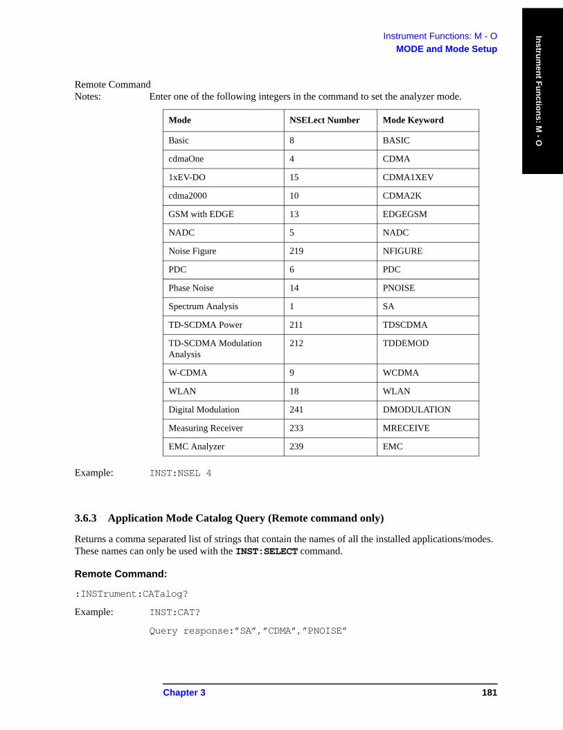
Instrument Functions: M - OMODE and Mode Setup
Instrument Functions: M
- O
Remote Command Notes: Enter one of the following integers in the command to set the analyzer mode.
Example: INST:NSEL 4
3.6.3 Application Mode Catalog Query (Remote command only)
Returns a comma separated list of strings that contain the names of all the installed applications/modes. These names can only be used with the INST:SELECT command.
Remote Command:
:INSTrument:CATalog?
Example: INST:CAT?
Query response:”SA”,”CDMA”,”PNOISE”
Mode NSELect Number Mode Keyword
Basic 8 BASIC
cdmaOne 4 CDMA
1xEV-DO 15 CDMA1XEV
cdma2000 10 CDMA2K
GSM with EDGE 13 EDGEGSM
NADC 5 NADC
Noise Figure 219 NFIGURE
PDC 6 PDC
Phase Noise 14 PNOISE
Spectrum Analysis 1 SA
TD-SCDMA Power 211 TDSCDMA
TD-SCDMA Modulation Analysis
212 TDDEMOD
W-CDMA 9 WCDMA
WLAN 18 WLAN
Digital Modulation 241 DMODULATION
Measuring Receiver 233 MRECEIVE
EMC Analyzer 239 EMC
Chapter 3 181

Instrument Functions: M - OMODE and Mode Setup
Inst
rum
ent F
unct
ions
: M -
O
3.6.4 Mode Setup (Spectrum Analysis Mode)
Enables you to change measurement settings common to all measurements in the MEASURE menu. In Spectrum Analysis mode, there are several built-in power measurements. Parameters that you set in the Mode Setup menu affect all of these measurements, see Volume 2, One-Button Power Measurements User’s and Programmer’s Reference for more information.
Key Path: Front-panel key
182 Chapter 3
Instrument Functions: P − Z
4 Instrument Functions: P − Z
This chapter provides key descriptions and programming information for the front-panel key functions of your analyzer that start with the letters P through Z. The front-panel functions are listed alphabetically and are described with their associated menu keys. The lower-level menu keys are arranged and described as they appear in your analyzer.
183
Instrument Functions: P − ZIn
stru
men
t Fun
ctio
ns: P
− Z
NOTE The front- and rear-panel features, along with the numeric keypad and alphanumeric softkey fundamentals, are illustrated and described in your Getting Started guide.
184 Chapter 4
Instrument Functions: P - ZPeak Search
Instrument Functions: P - Z
4.1 Peak SearchPlaces a marker on the highest peak and displays the search menu. If Peak Search Type (Param) is set to Excursion & Threshold, the peak found must meet the defined peak excursion and threshold values. (See “Search Param” on page 188.) Peaks that are less than 1% of the current span away from 0 Hz are ignored. For example, if Span is 1 MHz, peaks will not be found between −10 kHz and +10 kHz. If no valid peak is found, an error (No Peak Found) is displayed. To clear this message, press ESC before attempting another search.
The peak search parameters are Peak Threshold and Peak Excursion. All searches except Peak Search (Next Peak, Next Left, Next Right, Peak Table, SCPI “PEAKS” command) obey the Search Parameters, which means that only peaks which rise above the Peak Threshold by at least the Peak Excursion are found. Peak Search obeys then when Peak Search is in PARAM mode. When the Peak Search key is in MAX mode, the search parameters are ignored for a Peak Search.
NOTE You can go into the Peak Search menu without actually performing a Peak Search by using the front-panel Return key (assuming you have previously accessed the Peak Search menu). Press Return to navigate through the previously accessed menus until you return to the Peak Search menu.
Remote Command:
:CALCulate:MARKer[1]|2|3|4:MAXimum
Remote Command Notes: The :CALC:MARK:PEAK:SEARC:MODE MAX|PAR
command specifies how a peak is identified for use with the marker commands. See “Peak Search” on page 189.
Example: CALC:MARK2:MAX performs a peak search using marker 2.
CALC:MARK2:Y? queries the marker amplitude (Y-axis) value for marker 2. For more information on this command, see “Marker” on page 153.
CALC:MARK2:X? queries the marker frequency or time (X-axis) value for marker 2. For more information on this command, see “Marker” on page 153.
4.1.1 Next Peak
Places the marker on the next highest peak with an amplitude less than the current peak. The peak must meet the defined peak excursion and threshold values. Peaks that are less than 1% of the current span away from 0 Hz are ignored. If no valid peak is found, an error (No Peak Found) is displayed. Press ESC to clear this message before attempting another search. (Also see the Peak Excursn and Pk Threshold key descriptions.)
Key Path: Peak Search
State Saved: Not part of saved state.
Chapter 4 185
Instrument Functions: P - ZPeak Search
Inst
rum
ent F
unct
ions
: P -
Z
Remote Command:
:CALCulate:MARKer[1]|2|3|4:MAXimum:NEXT
Example: CALC:MARK2:MAX:NEXT selects marker 2 and moves it to the next highest peak.
4.1.2 Next Pk Right
Moves the marker to the next peak to the right of the current marker. The peak must meet the defined peak excursion and threshold limits. Peaks that are less than 1% of the current span away from 0 Hz are ignored. If no valid peak is found, an error “No Peak Found” is displayed. Press ESC to clear this message before attempting another search. (Also see the Peak Excursn and Pk Threshold key descriptions.)
Key Path: Peak Search
State Saved: Not part of saved state.
Remote Command:
:CALCulate:MARKer[1]|2|3|4:MAXimum:RIGHt
Example: CALC:MARK2:MAX:RIGH selects marker 2 and moves it to the next peak to the right.
4.1.3 Next Pk Left
Moves the marker to the next peak to the left of the current marker. The peak must meet the defined peak excursion and threshold limits. Peaks that are less than 1% of the current span away from 0 Hz are ignored. If no valid peak is found, an error “No Peak Found” is displayed. Press ESC to clear this message before attempting another search. (Also see the Peak Excursn and Pk Threshold key descriptions.)
Key Path: Peak Search
State Saved: Not part of saved state.
Remote Command:
:CALCulate:MARKer[1]|2|3|4:MAXimum:LEFT
Example: CALC:MARK2:MAX:LEFT selects marker 2 and moves it to the next peak to the left.
4.1.4 Min Search
Moves the active marker to the minimum detected amplitude value on the current trace.
Key Path: Peak Search
State Saved: Not part of saved state.
Remote Command:
:CALCulate:MARKer[1]|2|3|4:MINimum
Example: CALC:MARK:MIN selects marker 1 and moves it to the minimum amplitude value.
186 Chapter 4
Instrument Functions: P - ZPeak Search
Instrument Functions: P - Z
4.1.5 Pk-Pk Search
Finds and displays the amplitude and frequency (or time, if in zero span) differences between the highest and lowest trace points by setting a reference marker on the peak signal and placing a Δ marker on the minimum signal.
Key Path: Peak Search
State Saved: Not part of saved state.
Remote Command:
:CALCulate:MARKer[1]|2|3|4:PTPeak
Example: CALC:MARK:PTP
CALC:MARK:Y? queries the delta amplitude value for marker 1. For more information on this command, see “Marker” on page 153.
4.1.6 Mkr->CF
See “Mkr->CF” on page 169 for the command to select this function.
Key Path: Peak Search
4.1.7 Continuous Pk
When a marker is placed on a signal and Continuous Pk is pressed, the marker will remain on the signal even if the signal frequency changes, as long as the amplitude of the signal does not change by more than 3 dB from one sweep to another.
If the signal is lost, an attempt will be made to find it again and maintain the marker on the signal peak. If there are other signals on screen near the same amplitude, one of them may be found instead. Signals near 0 Hz cannot be maintained effectively, because they cannot be distinguished from the LO feedthrough, which is excluded by intent from the search algorithm.
NOTE This function is intended to maintain the marker on signals with a frequency that is changing, and an amplitude that is not changing.
Key Path: Peak Search
State Saved: Saved in Instrument State.
Factory Preset: Off
Remote Command:
:CALCulate:MARKer[1]|2|3|4:CPEak[:STATe] OFF|ON|0|1
:CALCulate:MARKer[1]|2|3|4:CPEak[:STATe]?
Remote Command Notes: This command may not be used to activate a given marker.
Chapter 4 187
Instrument Functions: P - ZPeak Search
Inst
rum
ent F
unct
ions
: P -
Z
Example: CALC:MARK:CPE ON
4.1.8 Search Param
Displays the search parameter criteria menu that enables you to adjust the parameters for the peak search functions. These parameters mean that only peaks that rise above the peak threshold by at least the peak excursion, and then drop by at least the peak excursion, are identified as peaks.
Key Path: Peak Search
Remote Command:
There is no remote command for this key.
4.1.8.1 Peak Excursn
Sets the minimum amplitude variation of signals that the marker can identify as a separate peak. For example, if a peak excursion value of 10 dB is selected, the marker Next Peak function moves only to peaks that rise more than 10 dB above the Peak Threshold and then fall back down by at least the Peak Excursn. This criteria applies to all traces. This function applies to Next Peak, Next Peak Left, and Next Peak Right. If Peak Search is set to Param, it also applies to Peak Search.
Key Path: Peak Search, Search Param
Dependencies/ Couplings: This function is not available when Y-Axis is set to Frequency instead of Amplitude.
State Saved: Saved in Instrument State.
Factory Preset: 6.0 dB
Factory Default: 6.0 dB
Terminators: dB
Default Terminator: dB
Resolution/Rounding/ Truncation: 0.01 dB
Knob Increment: 1 dB
Step Key Increment: 1 dB
Range: 0.0 dB to 100 dB
Remote Command:
:CALCulate:MARKer[1]|2|3|4:PEAK:EXCursion <rel_amplitude>
:CALCulate:MARKer[1]|2|3|4:PEAK:EXCursion?
Remote Command Notes: CALC:MARK:PEAK:SEAR:MODE must be set to PARameter if you want Peak
Search to take advantage of the threshold excursion.
Example: :CALC:MARK:PEAK:EXC 30 DB sets the minimum peak excursion requirement to
188 Chapter 4
Instrument Functions: P - ZPeak Search
Instrument Functions: P - Z
30 dB.
See the full example for the CALC:MARK:PEAK:SEAR:MODE command below.
4.1.8.2 Pk Threshold
Specifies the minimum signal level for the analyzer internal peak identification routine to recognize as a peak. To be considered a peak, a signal must rise above the Peak Threshold value by at least the value specified in Peak Excursn, then fall back down by at least the Peak Excursn. This applies to all traces and all windows. Press ESC or select another active function to hide the threshold line. Applies to Next Peak, Next Peak Left, and Next Peak Right. If Peak Search is set to Param, it also applies to Peak Search.
Key Path: Peak Search, Search Param
Dependencies/ Couplings: This function is not available when Y-Axis is set to Frequency instead of Amplitude.
State Saved: Saved in Instrument State.
Factory Preset: –90 dBm
Terminators: dBmV, dBμV, dBμΑ, V, W, A
Default Terminator: dBm
Resolution/Rounding/ Truncation: .001 dBm
Knob Increment: amp scale = LOG: 1% of dB/div or 0.01 (the larger of the two)
amp scale = LIN: 0.1 dBm
Step Key Increment: amp scale = LOG: dB/div
amp scale = LIN:
Range: From the current reference level to the bottom of the display range
Remote Command:
:CALCulate:MARKer[1]|2|3|4:PEAK:THReshold <ampl>
:CALCulate:MARKer[1]|2|3|4:PEAK:THReshold?
Remote Command Notes: CALC:MARK:PEAK:SEAR:MODE must be set to PARameter if you want peak
search to take advantage of the threshold excursion.
Example: :CALC:MARK:PEAK:THR -60 dBm sets the threshold to -60 dBm.
See the full example for the CALC:MARK:PEAK:SEAR:MODE command below.
4.1.8.3 Peak Search
Sets the mode for Peak Search to either Max or Param and applies to Peak Search only.
• Max (Maximum mode) places a marker on the highest peak whenever a Peak Search is performed.
Chapter 4 189

Instrument Functions: P - ZPeak Search
Inst
rum
ent F
unct
ions
: P -
Z
• Param (Parameter mode) searches only for peaks that meet the values set with Peak Excursn and Pk Threshold.
Key Path: Peak Search, Search Param
State Saved: Saved in Instrument State.
Factory Preset: Maximum
Factory Default: Maximum.
Remote Command:
:CALCulate:MARKer:PEAK[1]|2|3|4:SEARch:MODE PARameter|MAXimum
:CALCulate:MARKer:PEAK[1]|2|3|4:SEARch:MODE?
Remote Command Notes: If mode is set to MAXimum (Max), peak search will place the marker at the maximum
amplitude in the trace. If mode is set to PARameter (Param), peak search will place the marker at the highest peak that rises and falls by at least the peak excursion above the peak threshold. If no peak meets the excursion and threshold criteria, a No Peak Found error (error 202) is issued.
The following commands are not affected by the setting of CALC:MARK:PEAK SEAR:MODE. They will always use the parameter search mode that defines peaks based on peak excursion and peak threshold.
:CALCulate:MARKer[1]|2|3|4:MAXimum
:CALCulate:MARKer[1]|2|3|4:MAXimum:LEFT
:CALCulate:MARKer[1]|2|3|4:MAXimum:NEXT
:CALCulate:MARKer[1]|2|3|4:MAXimum:RIGHt
:CALCulate:MARKer:PEAK:TABLe:STATe OFF|ON|0|1
Example: CALC:MARK:PEAK:SEARC:MODE PAR sets the parameter search mode.
CALC:MARK:PEAK:THR –60 dBm sets the threshold to –60 dBm.
CALC:MARK:PEAK:EXC 30 dB sets the minimum peak excursion requirement to 30 dB.
CALC:MARK:STAT ON turns on marker number 1 and puts it on the active trace at mid screen.
CALC:MARK:MAX puts marker 1 on the highest peak that is at least 30 dB above the –60 dBm threshold.
:CALC:MARK:Y? returns the y-axis (amplitude) value of the marker in current y-axis units.
190 Chapter 4
Instrument Functions: P - ZPreset
Instrument Functions: P - Z
4.2 Preset
Presetting the instrument provides a known convenient starting point of the instrument state for making measurements. There are three possible actions when you press the Preset key:
• For preset type Mode (default), the green Preset key immediately performs a mode preset. See the descriptions below. Press System, Power On/Preset, Preset Type to select the preset type.
• For preset type Factory, the green Preset key immediately performs a factory preset. See the descriptions below. Press System, Power On/Preset, Preset Type to select the preset type.
• For preset type User, the green Preset key brings up a menu of preset key choices. You must press one of these keys to initiate an instrument preset.
— Pressing User Preset resets to the settings/values that you have previously defined as the User preset state using the Save User Preset key.
— Pressing Mode Preset does not change the mode; it only resets the current mode settings to the factory defaults.
— Pressing Factory Preset resets the settings for all the modes to the factory defaults. The factory preset mode is Spectrum Analysis with continuous sweep. If you are not already in the Spectrum Analysis mode, it switches to that mode.
• Pressing Save User Preset saves the current user settings.
None of these instrument presets resets “persistent” functions such as GPIB address, time/date display style, or auto-alignment state to the factory defaults. See “Restore Sys Defaults” on page 231.
If Preset Type is set to Factory in the System menu, pressing the Preset front-panel key performs a factory preset, which implements the following:
• Resets the analyzer to Spectrum Analyzer mode.
• Brings up the Freq menu, with no active function.
• Sets certain conditions, in all modes, to their default values.
• Clears the input and output buffers and all the trace data.
• Amplitude-correction factors are turned off, but remain in analyzer memory.
• Limit line testing is turned off, but the limit line tables remain in analyzer memory.
• The status byte is set to 0.
NOTE Recalling any state, including the user preset state, affects the conditions of more parameters than are affected by a factory preset. For example, external preamp gain and input impedance correction are not affected by a factory preset but are affected by a user preset.
Key Path: Front-panel key
Dependencies/ Couplings: Depends on the preset type (user, mode or factory) setting in the System, Power
On/Preset keys.
Chapter 4 191
Instrument Functions: P - ZPreset
Inst
rum
ent F
unct
ions
: P -
Z
SCPI Status Bits/ OPC Dependencies: Clears all pending OPC bits. The status byte is set to 0.
Remote Command:
:SYSTem:PRESet
Remote Command Notes: The SYSTem:PRESet command immediately presets the instrument state to values dependent on the preset type that is currently selected (FACTory, USER, MODE).
SYSTem:PRESet does not reset “persistent” functions such as IP address, time/date display style, or auto-alignment state to their factory defaults. Use SYSTem:PRESet:PERSistent. See “Restore Sys Defaults” on page 231.
SYSTem:PRESet:TYPE sets the type of preset. See “Preset Type” on page 211.
Example: :SYST:PRES:TYPE MODE sets the preset mode type to mode. See “Preset Type” on page 211.
:SYST:PRES presets the instrument to the currently selected preset type.
4.2.1 User Preset
This key is only available when the preset type is set to User. Press System, Power On/Preset, Preset Type, User.
Restores the analyzer to a user defined state that has been saved for all analyzer modes. You defined this state when Save User Preset was pressed. If the you have never saved a user preset state, then the factory preset state is stored as the user preset state. If the user preset state has been saved but the load fails for any reason, the error message: Unable to load user state is displayed in the status line and the state is reset to whatever it was before the Preset key was pressed. This can sometimes happen if firmware has been upgraded or applications have been (un)installed after the user preset state was saved. Save User Preset can be accessed by pressing System, Power On/Preset.
Key Path: Preset
Remote Command:
:SYSTem:PRESet See “:SYSTem:PRESet” on page 186.
Example: SYST:PRES:SAVE saves a user state that will be used for the preset
SYST:PRES:TYPE USER selects the user type preset
SYST:PRES immediately presets the analyzer to the user preset.
192 Chapter 4
Instrument Functions: P - ZPreset
Instrument Functions: P - Z
4.2.2 Mode Preset
This key is only available when the preset type is set to User. Press System, Power On/Preset, Preset Type, User.
A mode preset does not change the mode. It resets only the current mode settings to the factory defaults.
Key Path: Preset
History: Added with firmware revision A.02.00
Remote Command:
See “:SYSTem:PRESet” on page 186.
*RST
The *RST command always does a mode preset, except that it sets the instrument to do a single sweep/measurement instead of continuous.
Example: SYST:PRES:TYPE MODE selects the mode type preset
SYST:PRES immediately presets the current analyzer mode
4.2.3 Factory Preset
This key is available only when the preset type is set to User. Press System, Power On/Preset, Preset Type, Factory.
A factory preset returns instrument settings to the factory default values. If you are not already in the spectrum analysis mode, it switches to that mode. A factory preset does not reset “persistent” functions such as GPIB address, time/date display style, or auto-alignment state (see “Restore Sys Defaults” on page 231.)
Key Path: Preset
Remote Command:
:SYSTem:PRESet See “:SYSTem:PRESet” on page 186.
Remote Command Notes: This command will not reset “persistent” functions such as GPIB address, time/date
display style, or auto-alignment state to their factory defaults. Use SYSTem:PRESet:PERSistent. See “Restore Sys Defaults” on page 231.
Example: SYST:PRES:TYPE FACT selects the factory type preset
SYST:PRES immediately presets the analyzer to its factory defaults
Chapter 4 193

Instrument Functions: P - ZPreset
Inst
rum
ent F
unct
ions
: P -
Z
4.2.4 Save User Preset
This key is only available when the Preset Type is set to User. Press System, Power On/Preset, Preset Type, User.
Key Path: Preset (if preset type is set to User)
System, Power On/Preset. See “Save User Preset” on page 213
Remote Command:
:SYSTem:PRESet[:USER]:SAVE
Example: SYST:PRES:TYPE USER
SYST:PRES:SAVE
194 Chapter 4
Instrument Functions: P - ZPrint
Instrument Functions: P - Z
4.3 Print
Initiates an output of the display data to the currently defined printer. The screen remains frozen (no further sweeps are taken) until the data transfer to the printer is complete. Refer to the key description for Print Setup on page 196 for more information about the printer functions.
There must be a valid printer, already set up, for the print function to work. The Getting Started Guide includes additional printer installation information.
If you need to abort a print in progress, use the Esc (escape) key.
Key Path: Front-panel key
Remote Command:
:HCOPy[:IMMediate]
Example: HCOPY
4.3.1 Abort the Printout (Remote Command Only)
This command aborts the print that is currently in process.
Remote Command:
:HCOPy:ABORt
Example: HCOP:ABOR
4.3.2 Print Setup
Displays the functions that specify a particular printer and control its output.
Key Path: Front-panel key
Remote Command:
There is no remote command for this key.
Chapter 4 195
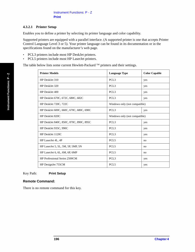
Instrument Functions: P - ZPrint
Inst
rum
ent F
unct
ions
: P -
Z
4.3.2.1 Printer Setup
Enables you to define a printer by selecting its printer language and color capability.
Supported printers are equipped with a parallel interface. (A supported printer is one that accepts Printer Control Language Level 3 or 5). Your printer language can be found in its documentation or in the specifications found on the manufacturer’s web page.
• PCL3 printers include most HP DeskJet printers.• PCL5 printers include most HP LaserJet printers.
The table below lists some current Hewlett-Packard ™ printers and their settings.
Key Path: Print Setup
Remote Command:
There is no remote command for this key.
Printer Models Language Type Color Capable
HP DeskJet 310 PCL3 yes
HP DeskJet 320 PCL3 yes
HP DeskJet 400 PCL3 yes
HP DeskJet 670C, 672C, 680C, 682C PCL3 yes
HP DeskJet 720C, 722C Windows only (not compatible)
HP DeskJet 600C, 660C, 670C, 680C, 690C PCL3 yes
HP DeskJet 820C Windows only (not compatible)
HP DeskJet 840C, 850C, 870C, 890C, 895C PCL3 yes
HP DeskJet 935C, 990C PCL3 yes
HP DeskJet 1120C PCL3 yes
HP LaserJet 4L, 4P PCL5 no
HP LaserJet 5, 5L, 5M, 5P, 5MP, 5N PCL5 no
HP LaserJet 6, 6L, 6M, 6P, 6MP PCL5 no
HP Professional Series 2500CM PCL3 yes
HP DesignJet 755CM PCL5 yes
196 Chapter 4
Instrument Functions: P - ZPrint
Instrument Functions: P - Z
4.3.2.1.1 Language
Lets you define your printer language as a PCL3 (Deskjet) or PCL5 (Laserjet) printer.
Key Path: Print Setup, Printer Setup
State Saved: Persistent, survives Preset and power cycle, but not saved in Instrument State.
Remote Command:
:HCOPy:DEVice:LANGuage PCL3|PCL5
:HCOPy:DEVice:LANGuage?
Example: HCOP:DEV:LANG PCL5
4.3.2.1.2 Color Capable
Allows you to define whether you printer is color capable (Yes) or not (No).
NOTE Color Capable does not specify whether you want a printout in color. See “Color” on page 199 for information.
Key Path: Print Setup, Printer Setup
State Saved: Persistent, survives Preset and power cycle, but not saved in Instrument State.
Remote Command:
:HCOPy:DEVice:COLor NO|YES
:HCOPy:DEVice:COLor?
Example: HCOP:DEV:COL YES
4.3.2.2 Orientation
Allows you to select either Portrait or Landscape printing. Landscape is not available with a PCL3 (Deskjet) printer.
Key Path: Print Setup
State Saved: Persistent, survives Preset and power cycle, but not saved in Instrument State.
Factory Preset: Portrait
Remote Command:
:HCOPy:PAGE:ORIentation LANDscape|PORTrait
:HCOPy:PAGE:ORIentation?
Example: HCOP:PAGE:ORI LAND
Chapter 4 197
Instrument Functions: P - ZPrint
Inst
rum
ent F
unct
ions
: P -
Z
4.3.2.2.1 Portrait
Selects Portrait orientation for the printouts from the analyzer.
Key Path: Print Setup, Orientation
Readback: Portrait
Remote Command:
See “Orientation” on page 197.
Example: HCOP:PAGE:ORI PORT
4.3.2.2.2 Landscape
Selects Landscape orientation for the printouts from the analyzer.
Key Path: Print Setup, Orientation
Readback: Landscape
Remote Command:
See “Orientation” on page 197.
Example: HCOP:PAGE:ORI LAND
4.3.2.3 Prints/Page
Selects the number of display prints per page when orientation is set to Portrait. The page will be ejected after the selected number of prints has been printed.
NOTE For Landscape printing, Prints/Page is always set to 1.
Key Path: Print Setup, Orientation
State Saved: Persistent, survives Preset and power cycle, but not saved in Instrument State.
Factory Preset: 1 print/page
Range: 2
Remote Command:
:HCOPy:PAGE:PRINts <integer>
:HCOPy:PAGE:PRINts?
Example: HCOP:PAGE:PRIN 2
4.3.2.4 Eject Page
Ejects your printed page.
Key Path: Print Setup, Orientation
198 Chapter 4
Instrument Functions: P - ZPrint
Instrument Functions: P - Z
Remote Command:
:HCOPy:ITEM:FFEed[:IMMediate]
Example: HCOP:ITEM:FFE
Ejects the page if prints per page is set to 2 and only 1 print has completed. Otherwise the page automatically ejects after the print is complete.
4.3.2.5 Page Size
Allows you to select from the following page sizes: Executive, Letter, Legal, Ledger, A4, and A3.
Key Path: Print Setup
State Saved: Persistent, survives Preset and power cycle, but not saved in Instrument State.
Factory Preset: Letter
Remote Command:
:HCOPy:PAGE:SIZE A|B|A3|A4|LETTer|LEGal|EXECutive|LEDGer
:HCOPy:PAGE:SIZE?
Remote Command Notes: Page size “A” is letter, and page size “B” is ledger. There is no size standardization for “legal” or “executive.”
Example: HCOP:PAGE:SIZE A4
4.3.2.5.1 Executive, Letter, Legal, Ledger, A4, or A3 Selectable page sizes available are as follows: Executive, Letter, Legal, Ledger, A4, and A3.
Key Path: Print Setup, Page Size
State Saved: Persistent, survives Preset and power cycle, but not saved in Instrument State.
Factory Preset: Letter
Remote Command:
:HCOPy:IMAGe:COLor[:STATe] OFF|ON|0|1
:HCOPy:IMAGe:COLor[:STATe]?
Example: HCOP:IMAG:COL ON
4.3.2.6 Color
Allows you to select between color or black and white printing on color-capable printers. This key is not available (grayed out) if Color Capable is set to No, see page 197.
Key Path: Print Setup
State Saved: Persistent, survives Preset and power cycle, but not saved in Instrument State.
Chapter 4 199
Instrument Functions: P - ZPrint
Inst
rum
ent F
unct
ions
: P -
Z
Factory Preset: Off
Remote Command:
:HCOPy:IMAGe:COLor[:STATe] OFF|ON|0|1
:HCOPy:IMAGe:COLor[:STATe]?
Example: HCOP:IMAG:COL ON
200 Chapter 4
Instrument Functions: P - ZRestart
Instrument Functions: P - Z
4.4 Restart
This function restarts a previously paused measurement at the beginning. If the measurement is active, it will stop it as soon as possible and restart it from the beginning.If no measurement is active and Sweep (Single) is selected, a new sweep is initiated.
When in Average (On) mode, (BW/Avg, Average) the averaging function is restarted (the trace is reset and the average number is reset to zero).
Key Path: Front-panel key. It can also be found under Meas Control.
Remote Command:
:INITiate:RESTart
Remote Command Notes: This command is equivalent to sending an :ABORt command followed by an :INITiate[:IMMediate] command. See “Abort the Sweep or Measurement (Remote Command Only)” on page 177. for more information.
Example: INIT:REST
Chapter 4 201

Instrument Functions: P - ZRestart
Inst
rum
ent F
unct
ions
: P -
Z
202 Chapter 4
Instrument Functions: P - ZSave
Instrument Functions: P - Z
4.5 SaveSaves analyzer states, traces, and screen data to a floppy (A:) drive or internal flash memory (C:) drive, as configured by the File menu. For example, if you have configured the instrument to save a trace to the C: drive, every time you press Save, it will save the current trace to a file with a new default trace file name.
You must first configure the save file Type, Format, Source, and Destination by using File, Save before pressing the front-panel Save key. Pressing the front-panel Save key will then be the same as pressing File, Save, Save Now.
Key Path: Front-panel key
Remote Command:
See “File” on page 105.
Use :MMEMory:STORe:SCReen <“file_name”>
Use :MMEMory:STORe:STATe 1,<“file_name”>
NOTE The MMEM:STOR:STAT command only saves the state of the Signal Analysis mode. Use *SAV to save all mode states.
Use :MMEMory:STORe:TRACe <label>,<“file_name”>
Use :MMEMory:STORe:LIMit LLINE1|LLINE2,<“file_name”>
Use :MMEMory:STORe:CORRection ANTenna|CABLe|OTHer|USER,<‘file_name’>
Chapter 4 203

Instrument Functions: P - ZSave
Inst
rum
ent F
unct
ions
: P -
Z
204 Chapter 4
Instrument Functions: P - ZSingle
Instrument Functions: P - Z
4.6 Single
If the analyzer is in continuous sweep mode and not in a measurement (Measure, Meas Off), pressing Single changes the sweep control to single sweep, and executes a sweep after the trigger condition is met. If the analyzer is already in single sweep, pressing Single executes a new sweep after the trigger condition is met.
Some instrument settings require more than one sweep to complete the measurement (see BW/Avg, Average), or if you have selected a measurement from the functions under the MEASURE key, this function sets the trigger system to be initiated only once. In this case the trigger condition can be met only once and then all the necessary sweeps will be executed to make the measurement or complete the averaging function.
With Average on (BW/Avg, Average (On)), pressing Single resets the average trace and starts the average again from a count of zero. Sweeps are averaged until N sweeps are then taken (where N is the average number), and then the sweep is halted.
State Saved: Single sweep setting is saved in Instrument State
Factory Preset: Continuous
Remote Command:
:INITiate[:IMMediate]
*TRG
Remote Command Notes: Use the :TRIGger[:SEQuence]:SOURce command to select the trigger source.
For more information, see “Trig” on page 271.
See also the *TRG command information in Chapter 6 , “Using the STATus System,” on page 337.
Example: *TRG
TRIG:IMM
Chapter 4 205

Instrument Functions: P - ZSingle
Inst
rum
ent F
unct
ions
: P -
Z
206 Chapter 4
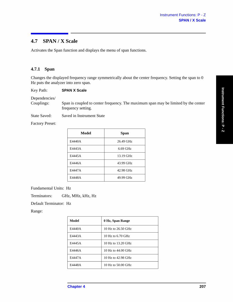
Instrument Functions: P - ZSPAN / X Scale
Instrument Functions: P - Z
4.7 SPAN / X Scale
Activates the Span function and displays the menu of span functions.
4.7.1 Span
Changes the displayed frequency range symmetrically about the center frequency. Setting the span to 0 Hz puts the analyzer into zero span.
Key Path: SPAN X Scale
Dependencies/ Couplings: Span is coupled to center frequency. The maximum span may be limited by the center
frequency setting.
State Saved: Saved in Instrument State
Factory Preset:
Fundamental Units: Hz
Terminators: GHz, MHz, kHz, Hz
Default Terminator: Hz
Range:
Model Span
E4440A 26.49 GHz
E4443A 6.69 GHz
E4445A 13.19 GHz
E4446A 43.99 GHz
E4447A 42.98 GHz
E4448A 49.99 GHz
Model 0 Hz, Span Range
E4440A 10 Hz to 26.50 GHz
E4443A 10 Hz to 6.70 GHz
E4445A 10 Hz to 13.20 GHz
E4446A 10 Hz to 44.00 GHz
E4447A 10 Hz to 42.98 GHz
E4448A 10 Hz to 50.00 GHz
Chapter 4 207

Instrument Functions: P - ZSPAN / X Scale
Inst
rum
ent F
unct
ions
: P -
Z
Remote Command:
[:SENSe]:FREQuency:SPAN <freq>
[:SENSe]:FREQuency:SPAN?
Example: FREQ:SPAN 2 GHZ
4.7.2 Span Zoom
Turns on signal tracking and activates the span function. Entering a new span value will then change the span while keeping the marker used for signal tracking centered on the screen. Pressing Span Zoom is the same as pressing: Frequency, Signal Track (On), and Span. See “Signal Track” on page 136.
Key Path: SPAN X Scale
State Saved: Saved in Instrument State
Remote Command:
No equivalent SCPI command.
4.7.3 Full Span
Changes the displayed frequency span to show the full frequency range of the analyzer. When using external mixing, it changes the displayed frequency span to the frequency range specified for the selected external mixing band.
Key Path: SPAN X Scale
Remote Command:
[:SENSe]:FREQuency:SPAN:FULL
Example: FREQ:SPAN:FULL
208 Chapter 4
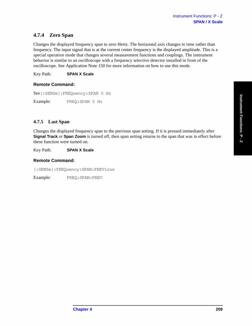
Instrument Functions: P - ZSPAN / X Scale
Instrument Functions: P - Z
4.7.4 Zero Span
Changes the displayed frequency span to zero Hertz. The horizontal axis changes to time rather than frequency. The input signal that is at the current center frequency is the displayed amplitude. This is a special operation mode that changes several measurement functions and couplings. The instrument behavior is similar to an oscilloscope with a frequency selective detector installed in front of the oscilloscope. See Application Note 150 for more information on how to use this mode.
Key Path: SPAN X Scale
Remote Command:
See[:SENSe]:FREQuency:SPAN 0 Hz
Example: FREQ:SPAN 0 Hz
4.7.5 Last Span
Changes the displayed frequency span to the previous span setting. If it is pressed immediately after Signal Track or Span Zoom is turned off, then span setting returns to the span that was in effect before these function were turned on.
Key Path: SPAN X Scale
Remote Command:
[:SENSe]:FREQuency:SPAN:PREVious
Example: FREQ:SPAN:PREV
Chapter 4 209

Instrument Functions: P - ZSPAN / X Scale
Inst
rum
ent F
unct
ions
: P -
Z
210 Chapter 4
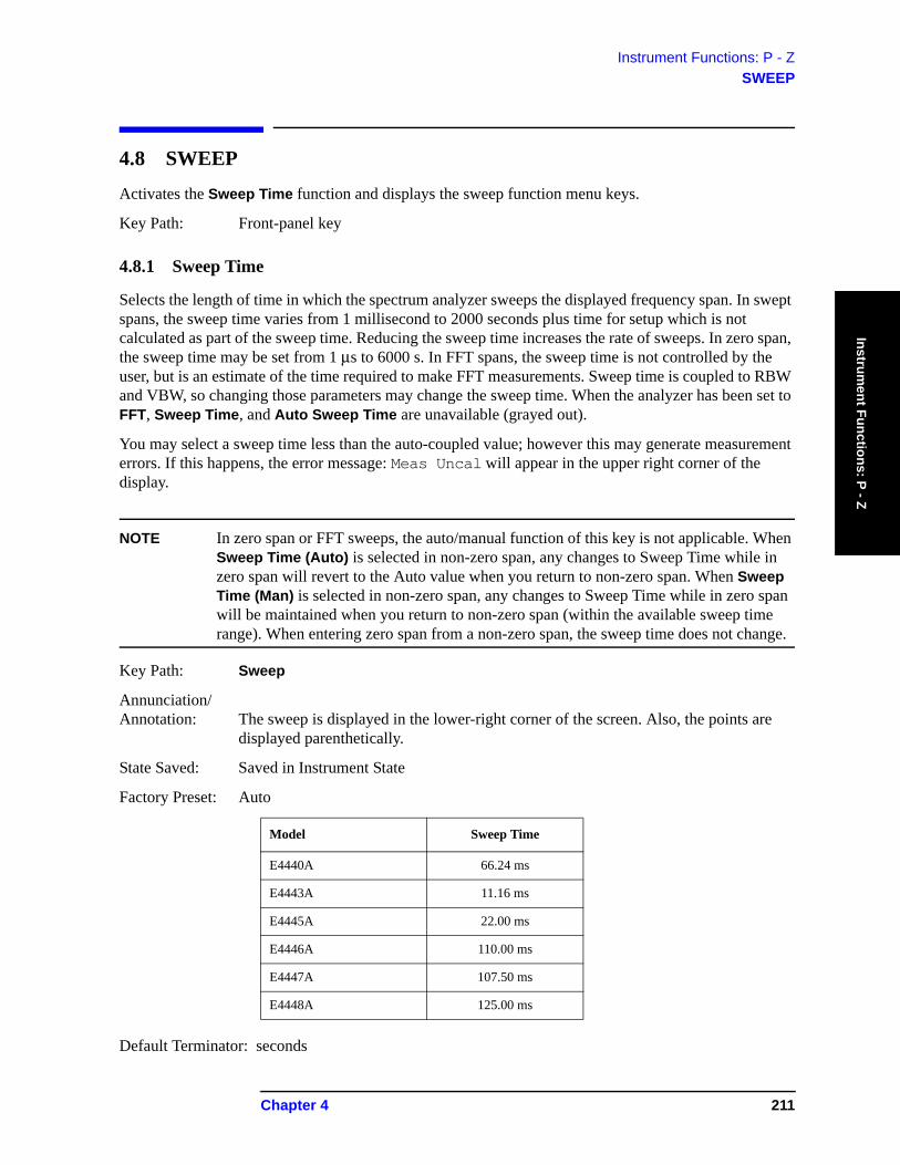
Instrument Functions: P - ZSWEEP
Instrument Functions: P - Z
4.8 SWEEP
Activates the Sweep Time function and displays the sweep function menu keys.
Key Path: Front-panel key
4.8.1 Sweep Time
Selects the length of time in which the spectrum analyzer sweeps the displayed frequency span. In swept spans, the sweep time varies from 1 millisecond to 2000 seconds plus time for setup which is not calculated as part of the sweep time. Reducing the sweep time increases the rate of sweeps. In zero span, the sweep time may be set from 1 μs to 6000 s. In FFT spans, the sweep time is not controlled by the user, but is an estimate of the time required to make FFT measurements. Sweep time is coupled to RBW and VBW, so changing those parameters may change the sweep time. When the analyzer has been set to FFT, Sweep Time, and Auto Sweep Time are unavailable (grayed out).
You may select a sweep time less than the auto-coupled value; however this may generate measurement errors. If this happens, the error message: Meas Uncal will appear in the upper right corner of the display.
NOTE In zero span or FFT sweeps, the auto/manual function of this key is not applicable. When Sweep Time (Auto) is selected in non-zero span, any changes to Sweep Time while in zero span will revert to the Auto value when you return to non-zero span. When Sweep Time (Man) is selected in non-zero span, any changes to Sweep Time while in zero span will be maintained when you return to non-zero span (within the available sweep time range). When entering zero span from a non-zero span, the sweep time does not change.
Key Path: Sweep
Annunciation/ Annotation: The sweep is displayed in the lower-right corner of the screen. Also, the points are
displayed parenthetically.
State Saved: Saved in Instrument State
Factory Preset: Auto
Default Terminator: seconds
Model Sweep Time
E4440A 66.24 ms
E4443A 11.16 ms
E4445A 22.00 ms
E4446A 110.00 ms
E4447A 107.50 ms
E4448A 125.00 ms
Chapter 4 211
Instrument Functions: P - ZSWEEP
Inst
rum
ent F
unct
ions
: P -
Z
Range: in zero span: 1 μs to 6000s
in swept spans: 1 ms to 4000s (Firmware Rev. A.10.00 and above)
Remote Command:
[:SENSe]:SWEep:TIME <time>
[:SENSe]:SWEep:TIME?
[:SENSe]:SWEep:TIME:AUTO OFF|ON|0|1
[:SENSe]:SWEep:TIME:AUTO?
Example: SWE:TIME 500 ms
SWE:TIME:AUTO OFF
4.8.2 Sweep
Switches the analyzer between continuous-sweep and single-sweep mode. Pressing the front-panel Single key will also put the analyzer in single-sweep mode, then take a sweep.
Key Path: Sweep
State Saved: Saved in Instrument State
Factory Preset: Continuous
Remote Command:
:INITiate:CONTinuous OFF|ON|0|1
:INITiate:CONTinuous?
:INITiate:[IMMediate]
Remote Command Notes: This command affects sweep if not in a measurement, and affects trigger when in a measurement. A “measurement” refers to any of the functions under the MEASURE key. This corresponds to continuous sweep or single sweep operation when not in a measurement, and continuous measurement or single measurement operation when in a measurement.
When not in a measurement, this command does the following:
• When ON at the completion of each sweep cycle, the sweep system immediately initiates another sweep cycle.
• When OFF, the sweep system remains in an “idle” state until CONTinuous is set to ON or an :INITiate[:IMMediate] command is received. On receiving the :INITiate[:IMMediate] command, it will go through a single sweep cycle, and then return to the “idle” state.
• The query returns 1 or 0 into the output buffer. 1 is returned when there is continuous sweeping. 0 is returned when there is only a single sweep.
212 Chapter 4
Instrument Functions: P - ZSWEEP
Instrument Functions: P - Z
When in a measurement, this command does the following:
• When ON at the completion of each trigger cycle, the trigger system immediately initiates another trigger cycle.
• When OFF, the trigger system remains in an “idle” state until CONTinuous is set to ON or an :INITiate[:IMMediate] command is received. On receiving the :INITiate[:IMMediate] command, it will go through a single trigger cycle, and then return to the “idle” state.
• The query returns 1 or 0 into the output buffer. 1 is returned when there is continuous triggering. 0 is returned when there is only a single trigger.
Use the :TRIGger[:SEQuence]:SOURce command to select the trigger source.
Example: INIT:CONT OFF
4.8.3 Auto Sweep Time
Switches the analyzer between normal and accuracy sweep states. Provides you the ability to select the rules for the control of sweep time when Sweep Time is set to Auto. Setting Auto Sweep Time to Accy will result in slower sweep times, usually about three times as long, but better amplitude accuracy for CW signals. The instrument specifications only apply when Sweep Time is set to Auto, and Auto Sweep Time is set to Accy.
Additional amplitude errors occur when Auto Sweep Time is set to Norm are usually well under 0.1 dB, though they are not guaranteed. Because of the faster sweep times and still low errors, Norm is the preferred setting of Auto Sweep Time. Also, when the Auto All function is performed, Auto Sweep Time is set to Norm.
Key Path: Sweep
Key Notes: Unavailable (grayed out) in Zero Span and FFT, but still shows user selected states (Norm or Accy). Goes to Norm on Auto All.
Dependencies/ Couplings: Key is grayed out in Zero Span and FFT, but still shows user selected states (Norm or
Accy). Goes to Norm on Auto All.
State Saved: Save
Factory Preset: Norm
Remote Command:
[:SENSe]:SWEep:TIME:AUTO:RULes NORMal|ACCuracy
[:SENSe]:SWEep:TIME:AUTO:RULes?
Example: SWE:TIME:AUTO:RUL ACC
Chapter 4 213

Instrument Functions: P - ZSWEEP
Inst
rum
ent F
unct
ions
: P -
Z
4.8.4 Gate
Turns the gate function on and off. When set On, the LO (local oscillator) sweeps whenever the gate conditions are satisfied by the signal at the Gate Source selected under Gate Setup. Turning on the Gate turns off Gate View (described below).
NOTE Some instruments require a hardware upgrade before gating can be used.
Because the LO is gated, the analyzer only sweeps while the gate is enabled. A complete sweep may require several gate events. The analyzer starts sweeping when the gate signal is enabled and stops when it is disabled, then continues sweeping when it is again enabled, etc. until the sweep is complete. So, the actual sweep time may be longer than the displayed time since it assumes that the instrument is sweeping continuously, not stopping and starting in response to the gating signal. In addition, the sweep time can be five times slower then expected because the measurement is using a short gate delay or a short gate length. This slowing is needed because the resulting resolution bandwidth does not allow the required hardware settling time before starting to sweep.
NOTE The enabled or disabled state of the gate appears at the TRIGGER 2 OUT rear panel connector. A TTL high output indicates that the gate function is enabled. This is always true, whether the Gate itself is turned On or Off (except during alignments).
Option 124 is a Video Out connection. The y-axis video out signal is not available when gating is being used.
Key Path: Sweep
Dependencies/ Couplings: Gate is unavailable/off when:
• FFT & Sweep setting is Manual:FFT
• Signal Track on
• Marker Count on
These function are unavailable whenever Gate is on:
• Manual:FFT
• Signal Track
• Presel Center
• Marker Count (frequency counter function)
State Saved: Saved in Instrument State
Factory Preset: Off
Remote Command:
[:SENSe]:SWEep:EGATe[:STATe] OFF|ON|0|1
[:SENSe]:SWEep:EGATe[:STATe]?
214 Chapter 4
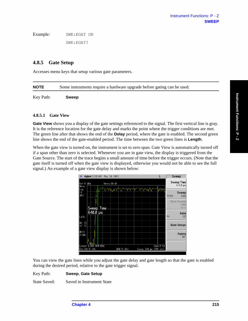
Instrument Functions: P - ZSWEEP
Instrument Functions: P - Z
Example: SWE:EGAT ON
SWE:EGAT?
4.8.5 Gate Setup
Accesses menu keys that setup various gate parameters.
NOTE Some instruments require a hardware upgrade before gating can be used.
Key Path: Sweep
4.8.5.1 Gate View
Gate View shows you a display of the gate settings referenced to the signal. The first vertical line is gray. It is the reference location for the gate delay and marks the point where the trigger conditions are met. The green line after that shows the end of the Delay period, where the gate is enabled. The second green line shows the end of the gate-enabled period. The time between the two green lines is Length.
When the gate view is turned on, the instrument is set to zero span. Gate View is automatically turned off if a span other than zero is selected. Whenever you are in gate view, the display is triggered from the Gate Source. The start of the trace begins a small amount of time before the trigger occurs. (Note that the gate itself is turned off when the gate view is displayed, otherwise you would not be able to see the full signal.) An example of a gate view display is shown below:
You can view the gate lines while you adjust the gate delay and gate length so that the gate is enabled during the desired period, relative to the gate trigger signal.
Key Path: Sweep, Gate Setup
State Saved: Saved in Instrument State
Chapter 4 215
Instrument Functions: P - ZSWEEP
Inst
rum
ent F
unct
ions
: P -
Z
Remote Command:
[:SENSe]:SWEep:EGATe:VIEW ON|OFF|1|0
[:SENSe]:SWEep:EGATe:VIEW?
Example: SWE:EGAT:VIEW ON
4.8.5.2 Polarity
Sets the polarity for the gate signal. When Positive (Pos) is selected, a positive-going edge will satisfy the gate condition, after the delay set with the Delay key. When Negative (Neg) is selected, a negative-going edge will satisfy the gate condition after the delay.
Key Path: Sweep, Gate Setup
State Saved: Saved in Instrument State
Factory Preset: Positive
Remote Command:
[:SENSe]:SWEep:EGATe:POLarity NEGative|POSitive
[:SENSe]:SWEep:EGATe:POLarity NEGative|POSitive?
Example: SWE:EGAT:POL NEG
SWE:EGAT:POL?
4.8.5.3 Delay
Controls the length of time from the time the gate condition is satisfied until the gate is enabled.
Key Path: Sweep, Gate Setup
State Saved: Saved in Instrument State
Factory Preset: 57.7 microseconds
Resolution: 100 ns
Range: 0.0 μs to 100 seconds
Remote Command:
[:SENSe]:SWEep:EGATe:DELay <time>
[:SENSe]:SWEep:EGATe:DELay?
Example: SWE:EGAT:DEL 100US
SWE:EGAT:DEL?
216 Chapter 4
Instrument Functions: P - ZSWEEP
Instrument Functions: P - Z
4.8.5.4 Length
Controls the length of time that the gate is enabled.
Key Path: Sweep, Gate Setup
State Saved: Saved in Instrument State
Factory Preset: 461.6 μs
Range: 10 μs to 0.5 s
Remote Command:
[:SENSe]:SWEep:EGATe:LENGth <time>
[:SENSe]:SWEep:EGATe:LENGth?
Example: SWE:EGAT:LENG 1ms
SWE:EGAT:LENG?
Chapter 4 217
Instrument Functions: P - ZSWEEP
Inst
rum
ent F
unct
ions
: P -
Z
4.8.5.5 Gate Source
Lets you select the input to which the gate signal will be applied.
Key Path: Sweep, Gate Setup
State Saved: Save
Factory Preset: Front (external 1 trigger input)
Remote Command:
[:SENSe]:SWEep:EGATe:SOURce EXTernal[1]|EXTernal2|RFBurst
where Ext1 selects the Front input and Ext2 selects the Rear input.
[:SENSe]:SWEep:EGATe:SOURce?
Example: SWE:EGAT:SOUR EXT2
4.8.5.5.1 Ext Front (Ext Trig In)
Selects the front panel external trigger input connector as the gate source and sets the voltage level at which the gate will trigger. Changes made to the trigger level setting with this key will also change the setting in the Trig menu.
NOTE Be careful about selecting trigger level values too far away from the trigger signal’s midpoint. If the signal has ringing, it can cause multiple triggers.
Key Path: Sweep, Gate Setup, Gate Source
State Saved: Saved in Instrument State
Factory Preset: 1.5 V
Range: −5 to +5 V
Remote Command:
See “Gate Source” on page 218
[:SENSe]:SWEep:EGATe:EXTernal[1]:LEVel <voltage>
[:SENSe]:SWEep:EGATe:EXTernal[1]:LEVel?
Example: SWE:EGAT:SOUR EXT1
SWE:EGAT:EXT1:LEV 2.5
218 Chapter 4
Instrument Functions: P - ZSWEEP
Instrument Functions: P - Z
4.8.5.5.2 Ext Rear (Trigger In)
Selects the rear panel external trigger input connector as the gate source and sets the voltage level at which the gate will trigger. Changes made to the trigger level setting with this key will also change the setting in the Trig menu.
This key also defines the voltage level at which the gate will trigger.
NOTE Be careful about selecting trigger level values too far away from the trigger signal’s midpoint. If the signal has ringing, it can cause multiple triggers.
Key Path: Sweep, Gate Setup, Gate Source
State Saved: Saved in Instrument State
Factory Preset: 1.5 V
Range: −5 to +5 V
Remote Command:
See “Gate Source” on page 218
[:SENSe]:SWEep:EGATe:EXTernal2:LEVel <voltage>
[:SENSe]:SWEep:EGATe:EXTernal2:LEVel?
Example: SWE:EGAT:SOUR EXT2
SWE:EGAT:EXT2:LEV 2.5
4.8.5.5.3 RF Burst (IF Wideband)
Selects the signal as the gate source and triggers on the RF burst. This is the same trigger function as found under the Trig key. See the trigger functions for more information.
Key Path: Sweep, Gate Setup, Gate Source
State Saved: Saved in Instrument State
Remote Command:
See “Gate Source” on page 218
Example: SWE:EGAT:SOUR RFB
4.8.6 Points
Sets the number of points per sweep, from 101 to 8192 in non-zero span and 2 to 8192 in zero span. Resolution of setting the sweep time will depend on the number of points selected. If Factory Preset is selected, or the analyzer power is cycled, the number of points per sweep will default to 601. The current value of points is displayed parenthetically, next to the sweep time in the lower-right corner of the display (refer to “Display Annotation” in your Getting Started guide).
Chapter 4 219
Instrument Functions: P - ZSWEEP
Inst
rum
ent F
unct
ions
: P -
Z
Changing the number of points has several effects on the analyzer. Since markers are read at the point location, the marker reading may change. All trace data for the active trace is cleared. If sweep is set to Cont (press Sweep, Sweep), a new sweep begins immediately. If average is set to On (press BW/Avg, Average), the averaging starts over with a count of 0. If limit lines are set to On (press Display, Limits, Modify, Limit 1 or 2), the limit lines are updated.
NOTE By selecting a number of sweep points greater than 601, you are optimizing frequency resolution and accuracy while accepting a reduced measurement speed. In addition to sweep points, the span, resolution bandwidth, video bandwidth, average detection and center frequency also affect measurement speed.
This function is coupled with the span setting. Increasing the span can change the number of sweep points. In order to maintain accurate measurements, the number of sweep points is increased if required to keep the width of each sweep point at most 150 MHz.
When zone span is set to On (press Span, Zone. Zone), each window has its own value for points.
Key Path: Sweep
State Saved: Saved in Instrument State
Factory Preset: 601
Range: 101 to 8192, 2 to 8192 in zero span
Remote Command:
[:SENSe]:SWEep:POINts <number of points>
[:SENSe]:SWEep:POINts?
Example: SWE:POIN 501
SWE:POIN?
220 Chapter 4
Instrument Functions: P - ZSystem
Instrument Functions: P - Z
4.9 System
Displays the System menu keys to control overall System functions. This is also the GPIB/USB LOCAL key. Pressing System (LOCAL) after the analyzer has been placed in the remote GPIB or USB mode returns it to the local mode and enables front-panel control, unless one of the buses is in the “Remote with Lockout State” (RWLS). During remote operation, “R” appears in the upper-right corner of the display indicating the instrument is in Remote mode. A “T”, “L”, or “S” may appear during remote operation, indicating Talk (GPIB), Listen (GPIB), or Service request (used for both GPIB and USB). Pressing the System (LOCAL) key removes the R symbol in the upper-right corner (provided neither bus is set to RWLS).
When the USB device is connected to the USB host and the device has been configured by the host, a black circle will appear next to the “R” in the upper-right corner of the display. When there is activity on the bus, the circle used to indicate that the USB devise is connected will change from a black circle with a gray center to a black circle with a flashing green center. After 1 second of inactivity, the center will change back to gray.
Key Path: Front-panel key
Remote Command:
There is no remote command for this key.
4.9.1 Show Errors
Accesses a display of the last 30 errors reported. The most recent error will appear at the top of the list. The first error listed will be the first error removed if the error list is longer than 30 entries. If the same error message occurs several times the error message will be incremented rather than added to the list as a new error message. If there is more than one of the same type of error, the date and time identify the first time and the last time an error occurred and the number of identical errors is shown.
NOTE A continuous recurring error reappears in the queue even if it had been cleared.
Symbol Description
R Remote
T Talk (GPIB only)
L Listen (GPIB only)
S Service Request
O USB Connected (flashing green center indicates bus activity)
Chapter 4 221

Instrument Functions: P - ZSystem
Inst
rum
ent F
unct
ions
: P -
Z
Key Path: System
Annunciation/ Annotation: Textual Information Screen
Dependencies/ Couplings: Removes any active functions.
Saved State: Not saved in Instrument State.
Factory Preset: Off
Remote Command:
:SYSTem:ERRor[:NEXT]?
Remote Command Notes: The :SYSTem:ERRor[:NEXT]? command queries the earliest entry to the error queue and then deletes that entry.
Example: SYST:ERR? returns <error number>,<“error string”>, for example -113,“Undefined header”.
*CLS clears the entire error queue.
4.9.1.1 Previous Page
Displays the previous page of the Show Errors screen. This key is unavailable (grayed out) if there is no previous page.
4.9.1.2 Next Page
Displays the next page of the Show Errors screen. This key is unavailable (grayed out) if there is no next page.
4.9.1.3 Clear Error Queue
Clears the front-panel error queue from the Show Errors display.
Key Path: System, Show Errors
Remote Command:
*CLS
4.9.1.4 Verbose
Adds additional information to the error messages returned by the SYSTem:ERRor? command. It indicates which remote command was executing when the error occurred and what about that command was unacceptable.
Key Path: System, Show Errors
State Saved: Not saved in Instrument State.
Preset: Off. This parameter retains the setting previously selected, even through a power
222 Chapter 4
Instrument Functions: P - ZSystem
Instrument Functions: P - Z
cycle.
Couplings and Dependencies: The verbose SCPI error debugging state is global to all the SCPI interfaces.
History: Added in version A.06.00
Remote Command:
:SYSTem:ERRor:VERBose OFF|ON|0|1
:SYSTem:ERRor:VERBose?
Remote Command Notes: The SYST:ERR? query returns the following types of information for each error. <error number>,”<error message>;<annotated SCPI command>”
Example: First set SYST:ERR:VERBOSE ON
If the command SENSe:FREQuently:CENTer 942.6MHz is sent, then sending SYST:ERR? returns:
−113,”Undefined header;SENSe:FREQuently:<Err>CENTer 942.6MHz $<NL>”
The <Err> shown after FREQuently shows you the spelling error. (The $<NL> is the typical representation for the command terminator.
If the command SENSe:FREQuency:CENTer 942.6Sec is sent, then sending SYST:ERR? returns:
−113,”Invalid suffix;SENSe:FREQuency:CENTer 942.6Sec<Err> $<NL>”
The <Err> shown after Sec shows you the invalid suffix.
4.9.2 Power On/Preset
Displays keys that enable you to define the instrument power-on state and user preset state.
NOTE If Power On is set to Preset, and Preset Type is set to Factory, then turning on the analyzer performs a factory preset. The last state of the analyzer (before it was turned off) is recalled if Power On is set to Last. The user preset state is recalled if Power On is set to Preset and Preset Type is set to User. (However, if there is no user preset state saved, the analyzer performs a factory preset.)
Key Path: System
Chapter 4 223

Instrument Functions: P - ZSystem
Inst
rum
ent F
unct
ions
: P -
Z
4.9.2.1 Power On
Enables you to set the state the analyzer will be put in when it is powered on. You can set the state to Last or Preset.
If Power On is set to Last, then the instrument returns to the last saved instrument state and all the modes are restored to that last state. The instrument saves its current state internally every 2 minutes. So the last saved state, that is restored at power-on, is the state at power-off or within a maximum of two minutes before power-off.
If Power On is set to Preset, the instrument state is determined by the preset type setting prior to turning the power off.
• Preset type Factory powers on in the Spectrum Analysis mode and all modes are set to their factory defaults.
• Preset type Mode powers on with the last mode the analyzer was in when it was powered off and presets that mode to the factory defaults. It also restores all other modes to their factory preset.
• Preset type User powers on with the user defined state, saved when a Save User Preset was last performed.
The setting (Last or Preset) of the Power On function is not changed by pressing Preset. Use the Power On/Preset menu key function to change the setting of the analyzer state that is recalled at power on. Limit lines are not recalled when the analyzer is powered on. Refer to “Preset” on page 191 for more information.
Key Path: System, Power On/Preset
State Saved: Survives preset and power cycle, but not saved in Instrument State.
SCPI Status Bits/ OPC Dependencies: None
Remote Command:
:SYSTem:PON:TYPE PRESet|LAST
:SYSTem:PON:TYPE?
Example: SYST:PON:TYPE LAST defines the power on type as the last state the analyzer was in before power was turned off.
SYST:PON:TYPE?
224 Chapter 4
Instrument Functions: P - ZSystem
Instrument Functions: P - Z
4.9.2.2 Preset Type
Enables you to select what type of preset will be initiated when you press the green Preset key or send the remote command, using SYST:PRES. Choose between Factory, Mode, or User defined presets.
Key Path: System, Power On/Preset
State Saved: Survives Preset and power cycle, but is not saved in Instrument State.
SCPI Status Bits/ OPC Dependencies: None
Preset: Does not change the Preset Type.
Factory Default: Mode
Remote Command:
:SYSTem:PRESet:TYPE FACTory|USER|MODE
:SYSTem:PRESet:TYPE?
Remote Command Notes: SYSTem:PRESet:USER:SAVE defines the user preset.
Example: SYST:PRES:TYPE FACT defines the type of preset as the factory preset.
4.9.2.2.1 User
Sets the preset type to User. When you do a preset, the instrument state that you have defined as the user preset setting is restored. Use the Save User Preset key to define your user preset settings. Refer to “Preset” on page 191 for more information. If you have not saved a user state, then the instrument will save the power-up state for you to use as a default user preset state.
Key Path: System, Power On/Preset, Preset Type
Readback: User
Annunciation/ Annotation: None
State Saved: Survives Preset and power cycle, but not saved in Instrument State.
SCPI Status Bits/ OPC Dependencies: None
Factory Default: Mode
Chapter 4 225
Instrument Functions: P - ZSystem
Inst
rum
ent F
unct
ions
: P -
Z
Remote Command:
“Preset Type’
Example: SYST:PRES[:USER]:SAVE saves the current state to be used as the preset user state.
SYST:PRES:TYPE USER defines the type of preset as the user preset.
With user preset selected, and a user state saved, use SYST:PRES to do a user preset.
4.9.2.2.2 Mode
Sets the preset type to “Mode.” When you do a preset, the current mode factory default instrument state will be restored. A mode preset does not change the mode. Refer to “Preset” on page 191 for more information.
Key Path: System, Power On/Preset, Preset Type
Readback: Mode
Annunciation/ Annotation: None
Dependencies/ Couplings: None
State Saved: Survives Preset and power cycle, but not saved in Instrument State.
SCPI Status Bits/ OPC Dependencies: None
Factory Default: Mode
Remote Command:
:SYSTem:PRESet:TYPE
“Preset Type’
Example: SYST:PRES:TYPE MODE defines the type of preset as the mode preset.
After you have selected mode as the preset type, use SYST:PRES to do a mode preset.
226 Chapter 4
Instrument Functions: P - ZSystem
Instrument Functions: P - Z
4.9.2.2.3 Factory
Sets the preset type to “Factory.” When you do a preset, all of the factory default instrument state will be restored. A factory preset switches the analyzer to the Spectrum Analysis mode and resets the settings of all the modes to the factory defaults (that is, Spectrum Analysis Mode with continuous sweep). Refer to “Preset” on page 191 for more information.
Key Path: System, Power On/Preset, Preset Type
Annunciation/ Annotation: Factory
State Saved: Survives Preset and power cycle, but not saved in Instrument State.
Factory Default: Mode
Remote Command:
“Preset Type’
Example: SYST:PRES:TYPE FACT defines the type of preset as the factory preset.
With factory preset selected, use SYST:PRES to do a factory preset.
4.9.2.3 Save User Preset
Saves the current state of the analyzer into the User Preset state register for recall when the instrument Preset Type is set to User and you perform a preset operation. After you save a state here, you must go to the Preset Type key and select User in order to have this state used as the preset state. Refer to “Preset” on page 191 key description for the default factory-configuration settings.
Key Path: System, Power On/Preset
Preset, if the preset type is set to User. See “Save User Preset” on page 194.
Annunciation/ Annotation: None
Dependencies/ Couplings: None
SCPI Status Bits/ OPC Dependencies: None
Remote Command:
:SYSTem:PRESet[:USER]:SAVE
Example: SYST:PRES:SAVE
Use SYST:PRES:TYPE USER to set factory preset type to “User.”
Then use SYST:PRES to do the preset.
Chapter 4 227

Instrument Functions: P - ZSystem
Inst
rum
ent F
unct
ions
: P -
Z
4.9.3 Time/Date
Displays the Time/Date function menu keys used to set and display the real-time clock.
Key Path: System
Remote Command:
There is no remote command for this key.
4.9.3.1 Time/Date
Turns the display of the real-time clock on or off.
Key Path: System, Time/Date
Annunciation/ Annotation: Current time and date are displayed in the upper-left corner of the screen.
State Saved: Survives Preset and power cycle, but not saved in Instrument State.
SCPI Status Bits/ OPC Dependencies: None
Factory Default: On (Restored by System, Restore Sys Defaults.)
Remote Command:
:DISPlay:ANNotation:CLOCk[:STATe] ON|OFF
:DISPlay:ANNotation:CLOCk[:STATe]?
Example: DISP:ANN:CLOC ON
4.9.3.2 Date Format
Enables you to set the date display to month-day-year or day-month-year. It is set to a month-day-year format when the instrument System Defaults are restored. This key only affects display of date at the top of the screen, not in the file catalog.
Key Path: System, Time/Date
State Saved: Survives Preset and power cycle, but not saved in Instrument State.
SCPI Status Bits/ OPC Dependencies: None
Factory Default: MDY (Restored by System, Restore Sys Defaults.)
228 Chapter 4
Instrument Functions: P - ZSystem
Instrument Functions: P - Z
Remote Command:
:DISPlay:ANNotation:CLOCk:DATE:FORMat MDY|DMY
:DISPlay:ANNotation:CLOCk:DATE:FORMat?
Example: DISP:ANN:CLOC:DATE:FORM DMY
4.9.3.3 Set Time
Enables you to set the time of the real-time clock. Enter the time in 24 hour HHMMSS format.
Key Path: System, Time/Date
Dependencies/ Couplings: None
State Saved: Survives Preset and power cycle, but not saved in Instrument State.
SCPI Status Bits/ OPC Dependencies: None
Factory Default: Not affected by “Restore Sys Defaults.”
Terminators: Unitless
Default Terminator: None
Range: Hour (HH): 00 to 23.
Minute (MM): 00 to 59.
Second (SS): 00 to 59.
Remote Command:
:SYSTem:TIME <hour>,<minute>,<second>
:SYSTem:TIME?
Example: SYST:TIME 12,42,00 Sets the clock to 12:42:00 PM.
4.9.3.4 Adjust Time Setting (Remote Command Only)
Adjust the instruments internal time by the value entered.
Key Path: System, Time/Date
SCPI Status Bits/ OPC Dependencies: None
Terminators: No units are allowed with the command.
DefaultTerminator seconds
Chapter 4 229

Instrument Functions: P - ZSystem
Inst
rum
ent F
unct
ions
: P -
Z
Remote Command:
:SYSTem:TIME:ADJust <seconds>
Example: SYST:TIME:ADJ 3600 will advance the time one hour.
SYST:TIME:ADJ -86400 will back the date up one day, without changing the time of day (minutes or seconds).
4.9.3.5 Set Date
Allows you to set the date of the real-time clock. Enter the date in the YYYYMMDD format.
Key Path: System, Time/Date
State Saved: Survives Preset and power cycle, but not saved in Instrument State. Not restored by System, Restore Sys Defaults.
SCPI Status Bits/ OPC Dependencies: None
Factory Default: Not affected by “Restore Sys Defaults.”
Terminators: Unitless
Range: Year (YYYY): 1970 to 2029
Month (MM):01 to 12
Day: 01 to 30 or 31 (depending on the month)
Remote Command:
:SYSTem:DATE <year>,<month>,<day>
:SYSTem:DATE?
Example: SYST:DATE 2000,12,24 Sets the date to December 24, 2000
230 Chapter 4
Instrument Functions: P - ZSystem
Instrument Functions: P - Z
4.9.4 Alignments
Displays functions that control the automatic alignment of the instrument and load default values for the alignment system.
NOTE Most CALibration commands execute in the background, permitting other SCPI commands to be processed concurrently. If a measurement command is sent right after a CALibration command, there can be interaction between background alignments and the measurement. The *WAI command should be issued after any CALibration command and before the measurement command. Note that sending the query form of a CAL? command will automatically hold off any following commands until the query value is returned.
Bit 0 (CALibration) must be set to 1 in the STATus:OPERation:ENABle register to ensure that the *WAI command waits for calibration to complete. This is the factory preset and *RST setting.
Key Path: System
Remote Command:
There is no remote command for this key.
4.9.4.1 Auto Align
Allows you to turn the instrument automatic alignment On or Off. or select Alert to be alerted that alignments are needed.
• Off - This setting has been changed to work the same as the Alert selection. With firmware revision A.09.18 or later, it is very important to know that you have turned off the alignments since, over time, leaving them permanently off will result in measurement inaccuracies.
• On - The instrument behaves like the Alert, but will automatically perform a full alignment when it is needed. In addition, every 15 minutes passing or 1.5 degrees temperature change will cause just the RF system gain to be aligned, to achieve the best absolute amplitude accuracy. For either alignment, the instrument will stop any measurement currently in process, perform the full alignment, then restart the measurement from the beginning (similar to pressing Restart). If any alignment FAILs or is ABORTed by the user (for example, ESCape key), the instrument will wait 5 minutes before retrying the necessary alignment. This helps to avoid infinite recursive loops of alignment behavior in the event of broken hardware. When Auto Align, On is selected, “AA” appears along the left edge of the display. Also see “Align All Now” on page 232.
• Alert - A 3 degree (Celsius) temperature change or a time span of 24 hours since the last successful Full alignment (for example, Align All Now) will trigger an alert that alignments need to be done, but no alignments will be performed without user input. When Auto Align, Alert is selected, “AL” appears along the left edge of the display.
Chapter 4 231
Instrument Functions: P - ZSystem
Inst
rum
ent F
unct
ions
: P -
Z
There are 2 very quick alignments, invisible to the user, that are done every few minutes or when certain settings are changed. These still occur, even if AutoAlign is set to Off. These alignments are the Current SysGain and Current IF Flatness methods which can also be forced to occur by user under the Align Subsys menu.
Key Path: System, Alignments
State Saved: Survives Preset and power cycle, but not saved in Instrument State.
Factory Preset: Not affected by Preset.
Factory Default: On (Restored by System, Restore Sys Defaults.)
Remote Command:
:CALibration:AUTO OFF|ON|ALERt
:CALibration:AUTO?
Example: CAL:AUTO ON
4.9.4.2 Align All Now
Immediately executes an alignment cycle of all the subsystems (Align RF, Align IF, Align ADC, and Align Current Sys Gain). The instrument will stop any measurement currently underway, perform the full alignment, then restart the measurement from the beginning (similar to pressing the Restart key). All other operations are stopped and the alignments will be visible on the display.
Key Path: System, Alignments
Remote Command:
:CALibration[:ALL] Performs a full alignment.
The following three commands perform a full alignment and return a number indicating the success of the alignment. A zero is returned if the alignment is successful. A one is returned if any part of the alignment fails.
:CALibration[:ALL]?
*CAL?
*TST?
Example: CAL? The query performs a full alignment and returns a number indicating the success of the alignment. A zero is returned if the alignment is successful.
4.9.4.3 Frequency Corrections (Remote Command Only)]
Turns the internal frequency corrections on/off.
Saved State: Not saved in instrument state
Factory Preset: On
Factory
232 Chapter 4
Instrument Functions: P - ZSystem
Instrument Functions: P - Z
Default: On
Remote Command:
:CALibration:FREQuency[:STATe] OFF|ON|0|1
:CALibration:FREQuency[:STATe]?
Example: CAL:FREQ OFF
4.9.4.4 Align Subsys
Accesses the keys to immediately execute an alignment of one of the subsystems (Align RF, Align IF, Align ADC, and Align Current Sys Gain). When one of the subsystem alignments is started, all other operations are stopped and any alignment messages will be visible on the display.
Key Path: System, Alignments
Remote Command:
There is no remote command for this key.
4.9.4.4.1 Align RF
Initiates an alignment on the RF assembly.
Key Path: System, Alignments, Align Subsys
Annunciation/ Annotation: Displays a series of pop-up message boxes, indicating an alignment is in progress.
If a signal is present that interferes with the alignment a message Align RF 50 MHz signal detected. will be displayed.
SCPI Status Bits/ OPC Dependencies: Status questionable calibration. Bits 3, 11, or 12 will be set if Align RF fails
Remote Command:
:CALibration:RF
:CALibration:RF?
Remote Command Notes: The query performs the alignment and returns a zero if the alignment is successful.
Example: CAL:RF?
Chapter 4 233

Instrument Functions: P - ZSystem
Inst
rum
ent F
unct
ions
: P -
Z
4.9.4.4.2 Align IF
Initiates an alignment on the IF assembly.
Key Path: System, Alignments, Align Subsys
Annunciation/ Annotation: Displays a series of pop-up message boxes indicating alignment progress.
SCPI Status Bits/ OPC Dependencies: Status questionable calibration Bit 4 will be set if Align RF fails.
Remote Command:
:CALibration:IF
:CALibration:IF?
Remote Command Notes: The query performs the alignment and returns a zero if the alignment is successful.
Example: CAL:IF?
4.9.4.4.3 Align ADC
Initiates an alignment on the ADC circuitry.
Key Path: System, Alignments, Align Subsys
Annunciation/ Annotation: Message boxes indicating alignment of ADC progress.
SCPI Status Bits/ OPC Dependencies: Status questionable calibration Bit 6 will be set if Align ADC fails.
Remote Command:
:CALibration:ADC
:CALibration:ADC?
Remote Command Notes: The query performs the alignment and returns a zero if the alignment is successful.
Example: CAL:ADC?
234 Chapter 4
Instrument Functions: P - ZSystem
Instrument Functions: P - Z
4.9.4.4.4 Align Current IF Flatness
Initiates an alignment of the current IF flatness, for the purpose of improving absolute amplitude within FFT Sweeps and improving group delay in some digital demodulation measurements.
Key Path: System, Alignments, Align Subsys
Annunciation/ Annotation: Displays a series of pop-up message boxes explaining what is being aligned (a subset of the Align All Now message boxes).
Remote Command:
:CALibration:FLATness:IF
:CALibration:FLATness:IF?
Remote Command Notes: The query performs the alignment and returns a zero if the alignment is successful.
Example: CAL:FLAT:IF?
4.9.4.4.5 Align Current SysGain
Initiates a fine-tuning adjustment of the system gain, primarily to correct for small amplitude variations that occur as resolution BW is switched.
Key Path: System, Alignments, Align Subsys
Annunciation/ Annotation: Displays a series of pop-up message boxes explaining what is being aligned (a subset
of the Align All Now message boxes).
Remote Command:
:CALibration:GAIN:CSYStem
:CALibration:GAIN:CSYStem?
Remote Command Notes: The query performs the alignment and returns a zero if the alignment is successful.
Example: CAL:GAIN:CSYS?
4.9.4.4.6 Align Audio Digitizer Gain
Initiates an alignment of the various gain settings of the 100 kΩ input path (Option 107)
Key Path: System, Alignments, Align Subsys
Annunciation/ Annotation: Displays a series of pop-up message boxes explaining what is being aligned (a subset
of the Align All Now message boxes).
Chapter 4 235

Instrument Functions: P - ZSystem
Inst
rum
ent F
unct
ions
: P -
Z
Remote Command:
:CALibration:GAIN:ADIGitizer
:CALibration:GAIN:ADIGitizer?
Remote Command Notes: The query performs the alignment and returns a zero if the alignment is successful.
Example: CAL:GAIN:ADIG?
History: Added with firmware revision A.09.00
4.9.4.5 Restore Align Defaults
Loads the default values for the alignment system, turns on the frequency corrections, and resets the timebase to the factory values. Align All Now must be executed 3 times after pressing Restore Align Defaults to meet specifications.
Key Path: System, Alignments
Annunciation/ Annotation: System Alignments, Align Now All required.
Dependencies/ Couplings: None
SCPI Status Bits/ OPC Dependencies: Status questionable calibration Bit 14 will be set.
Remote Command:
:CALibration:DATA:DEFault
Example: CAL:DATA:DEF
4.9.4.6 Select Time Corrections (Remote Command Only)
Controls time corrections used to compensate for the complex (magnitude and phase) response of the analog and digital IF hardware. When only scalar (magnitude) FFT flatness is required, time corrections take more CPU cycles and so are less efficient than frequency corrections. For demod or other time-based (not FFT) measurements, only time corrections can improve the flatness that results from imperfect IF hardware. When the time correction functionality is set to Auto (the default), the individual measurements activate the corrections when they are needed.
NOTE Turning time corrections on or off affects all measurements. Time corrections should be left in Auto unless you have specific reasons for forcing them on or off.
Always return time corrections to Auto.
Factory Preset: Auto
236 Chapter 4
Instrument Functions: P - ZSystem
Instrument Functions: P - Z
Remote Command:
:CALibration:TCORrections AUTO|ON|OFF
Example: CAL:TCOR OFF
4.9.5 Config I/O
Displays the keys and menus that enable you to identify and change the current GPIB address and LAN settings.
Key Path: System
Remote Command:
There is no remote command for this key.
4.9.5.1 GPIB Address
Shows the current GPIB address and allows you to change this value using the numeric keyboard. The new value is displayed in the active function area. The GPIB port is always active. The knob and step keys are not active for this function.
Key Path: System, Config I/O
State Saved: Survives Preset and power cycle, but not saved in Instrument State.
SCPI Status Bits/ OPC Dependencies: None
Factory Default: 18 (Reset by System, Restore Sys Defaults.)
Terminators: Enter
Default Terminator: None
Resolution/Rounding/ Truncation: Integer
Knob Increment: 1
Step Key Increment: 1
Range: 0 to 30
Remote Command:
:SYSTem:COMMunicate:GPIB[:SELF]:ADDRess <integer>
:SYSTem:COMMunicate:GPIB[:SELF]:ADDRess?
Example: SYST:COMM:GPIB:ADDR 20
Chapter 4 237
Instrument Functions: P - ZSystem
Inst
rum
ent F
unct
ions
: P -
Z
4.9.5.2 IP Address
Allows you to set the IP (internet protocol) address, domain name and node (host) name for the instrument. The IP address of the instrument can be changed by entering a numeric address composed of numbers and decimal points. Press ENTER to complete the entry.
Key Path: System, Config I/O
State Saved: Survives Preset and power cycle, but not saved in Instrument State.
Factory Default: 10.10.10.10 (Not reset by System, Restore Sys Defaults.)
Remote Command:
:SYSTem:COMMunicate:LAN[:SELF]:IP <string>
:SYSTem:COMMunicate:LAN[:SELF]:IP?
Example: SYST:COMM:LAN:IP “150.222.50.52 mypsa”
Sets the IP address to 150.222.50.52 and sets the host name to mypsa.
4.9.5.3 Host Name
Displays the host name of the instrument. Pressing the key activates the alpha editor, which enables you to change the host name. (Press ENTER to complete the entry.)
NOTE This does not change your LAN system representation of the host name. You must work through your local system administrator to change the host name. Changing it in the instrument only changes the displayed information. It does not enable LAN access with the new name.
Key Path: System, Config I/O
State Saved: Survives Preset and power cycle, but not saved in Instrument State.
Factory Default: mypsa (Not reset by System, Restore Sys Defaults.)
Remote Command:
See above command :SYSTem:COMMunicate:LAN[:SELF]:IP <string>
Example: SYST:COMM:LAN:IP “150.222.50.52 mypsa”
Sets the IP address to 150.222.50.52 and sets the host name to mypsa.
4.9.5.4 Host ID (Remote Command Only)
Enables you to query the host ID remotely. The current value of the host ID can be viewed on the display by pressing System, Show System.
SCPI Status Bits/ OPC Dependencies: None
238 Chapter 4
Instrument Functions: P - ZSystem
Instrument Functions: P - Z
Factory Default: Value is unique to your instrument (Not reset by System, Restore Sys Defaults.)
Remote Command:
:SYSTem:HID?
Remote Command Notes: The host ID cannot be set remotely, it can only be queried.
Example: SYST:HID?
4.9.5.5 Subnet Mask
Changes the subnet mask of the instrument. The subnet mask is a 32-bit address mask used in IP networks to indicate the bits of an IP address that are used for the subnet address. The default address is 255.255.0.0 for a class B network
Key Path: System, Config I/O
State Saved: Survives Preset and power cycle, but not saved in Instrument State.
Factory Default: 255.255.0.0 (Not reset by System, Restore Sys Defaults.)
History: Added with firmware revision A.03.00.
Remote Command:
There is no equivalent remote command.
4.9.5.6 Gateway Address
Allows you to set the gateway address. The gateway address feature is used to manipulate the gateway used to reach the destination. The gateway address can be changed by entering a numeric address composed of numbers and decimal points. Press ENTER to complete the entry.
Key Path: System, Config I/O
State Saved: Survives Preset and power cycle, but not saved in Instrument State.
Factory Default: 0.0.0.0 (Not reset by System, Restore Sys Defaults.)
History: Added with firmware revision A.03.00.
Remote Command:
There is no remote command for this key.
4.9.5.7 SCPI LAN
Displays keys to enable SCPI functionality over the LAN. There are a number of different ways to send SCPI remote commands to the instrument over the LAN. It can be a problem to have multiple users simultaneously accessing the instrument over the LAN. These keys allow you to limit that somewhat by disabling the telnet socket and/or SICL capability.
Key Path: System, Config I/O
Chapter 4 239

Instrument Functions: P - ZSystem
Inst
rum
ent F
unct
ions
: P -
Z
Remote Command:
There is no remote command for this key.
4.9.5.7.1 SCPI Telnet
Turns on/off the SCPI LAN telnet capability, allowing you to limit SCPI access over LAN via telnet.
Key Path: System, SCPI Lan
State Saved: Survives Preset and power cycle, but not saved in Instrument State.
SCPI Status Bits/ OPC Dependencies: None
Factory Default: On (Reset by System, Restore Sys Defaults.)
Remote Command:
:SYSTem:COMMunicate:LAN:SCPI:TELNet:ENABle OFF|ON|0|1
:SYSTem:COMMunicate:LAN:SCPI:TELNet:ENABle?
Example: SYST:COMM:LAN:SCPI:TELN:ENAB ON
4.9.5.7.2 SCPI Socket
Turns on/off the capability of establishing Socket LAN sessions. This allows you to limit SCPI access over LAN via socket sessions.
Key Path: System, SCPI Lan
State Saved: Survives Preset and power cycle, but not saved in Instrument State.
SCPI Status Bits/ OPC Dependencies: None
Factory Default: On (Reset by System, Restore Sys Defaults.)
Remote Command:
:SYSTem:COMMunicate:LAN:SCPI:SOCKet:ENABle OFF|ON|0|1
:SYSTem:COMMunicate:LAN:SCPI:SOCKet:ENABle?
Example: SYST:COMM:LAN:SCPI:SOCK:ENAB ON
240 Chapter 4
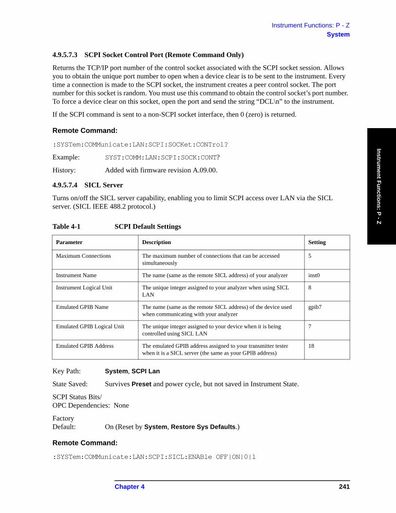
Instrument Functions: P - ZSystem
Instrument Functions: P - Z
4.9.5.7.3 SCPI Socket Control Port (Remote Command Only)
Returns the TCP/IP port number of the control socket associated with the SCPI socket session. Allows you to obtain the unique port number to open when a device clear is to be sent to the instrument. Every time a connection is made to the SCPI socket, the instrument creates a peer control socket. The port number for this socket is random. You must use this command to obtain the control socket’s port number. To force a device clear on this socket, open the port and send the string “DCL\n” to the instrument.
If the SCPI command is sent to a non-SCPI socket interface, then 0 (zero) is returned.
Remote Command:
:SYSTem:COMMunicate:LAN:SCPI:SOCKet:CONTrol?
Example: SYST:COMM:LAN:SCPI:SOCK:CONT?
History: Added with firmware revision A.09.00.
4.9.5.7.4 SICL Server
Turns on/off the SICL server capability, enabling you to limit SCPI access over LAN via the SICL server. (SICL IEEE 488.2 protocol.)
Key Path: System, SCPI Lan
State Saved: Survives Preset and power cycle, but not saved in Instrument State.
SCPI Status Bits/ OPC Dependencies: None
Factory Default: On (Reset by System, Restore Sys Defaults.)
Remote Command:
:SYSTem:COMMunicate:LAN:SCPI:SICL:ENABle OFF|ON|0|1
Table 4-1 SCPI Default Settings
Parameter Description Setting
Maximum Connections The maximum number of connections that can be accessed simultaneously
5
Instrument Name The name (same as the remote SICL address) of your analyzer inst0
Instrument Logical Unit The unique integer assigned to your analyzer when using SICL LAN
8
Emulated GPIB Name The name (same as the remote SICL address) of the device used when communicating with your analyzer
gpib7
Emulated GPIB Logical Unit The unique integer assigned to your device when it is being controlled using SICL LAN
7
Emulated GPIB Address The emulated GPIB address assigned to your transmitter tester when it is a SICL server (the same as your GPIB address)
18
Chapter 4 241
Instrument Functions: P - ZSystem
Inst
rum
ent F
unct
ions
: P -
Z
:SYSTem:COMMunicate:LAN:SCPI:SICL:ENABle?
Example: SYST:COMM:LAN:SCPI:SICL:ENAB ON
4.9.5.7.5 USB Connection Type (Remote Command Only)
Allows you to determine what USB speed was negotiated.
Remote Command:
:SYSTem:COMMunicate:USB:CONNection?
Remote Command Notes: This is a query only command. It returns one of the following possible enumerations:
NONE Indicates either no USB connection has been made or Option 111 is not installed.
LSPeed Indicates a USB low speed connection (1.5 Mbps). This is reserved for future use.
HSPeed Indicates that a USB high speed connection (480 Mbps) has been negotiated.
FSPeed Indicates that a USB full speed connection (12 Mbps) has been negotiated.
Example: SYST:COMM:USB:CONN?
History: Added with firmware revision A.09.00.
4.9.5.7.6 USB Connection Status (Remote Command Only)
Allows you to determine the current status of the USB connection.
Remote Command:
:SYSTem:COMMunicate:USB:STATus?
Remote Command Notes: This is a query only command. It returns one of the following possible enumerations:
SUSPended Indicates that the USB bus is currently in its suspended state. The bus is in the suspended state when the bus is not connected to a controller, the controller is currently powered off, or the controller has explicitly placed the USB device in the suspended state. When in the suspended state, no USB activity (including start of frame packets) is received.
ACTive Indicates that the USB is in the active state. When the device is in the active state, it is receiving periodic start of frames but is not necessarily receiving or transmitting data.
Example: SYST:COMM:USB:STAT?
History: Added with firmware revision A.09.00.
4.9.5.7.7 USB Packet Count (Remote Command Only)
Allows you to determine the number of packets received and transmitted on the USB bus.
Remote Command:
:SYSTem:COMMunicate:USB:PACKets?
242 Chapter 4
Instrument Functions: P - ZSystem
Instrument Functions: P - Z
Remote Command Notes: This is a query only command. It returns two integers. The first is the number of packets received since power-on, and the second is the number of packets transmitted since power-on. If the Option 111 interface is not installed, the query will return 0,0.
Example: SYST:COMM:USB:PACK?
History: Added with firmware revision A.09.00.
4.9.6 Reference
Displays functions that control the external frequency reference.
Key Path: System
Remote Command:
There is no remote command for the system key. Refer to the remote commands in the “Freq Ref’ section. These commands enables you to select an external frequency reference source and specify a value.
4.9.6.1 Freq Ref
Specifies the frequency reference as being internal or external. If the frequency reference is specified as internal, the frequency of the reference is automatically identified as being 10 MHz. If the frequency reference is specified as external, you must enter the frequency of the external reference being used. If External Reference is selected, Ext Ref will appear on the right side of the display.
The frequency of an external frequency reference is not automatically detected. If an external frequency source is selected, the frequency of the source must be entered.
If Ext is selected, and you press Freq Ref, Ext will remain selected and the Ext reference frequency will become the active function. If Freq Ref is pressed again, Int will become selected (at 10 MHz). The Ext reference frequency is remembered and will be used again if Ext is selected.
If the external reference is missing or out of range, or the frequency reference is unlocked, the message “External reference missing or out of range”, will appear on the display.
Key Path: System, Reference
State Saved: Not saved in Instrument State. Neither the external reference frequency nor the state of this function (Int or Ext) are affected by factory preset or power cycle. Reset to the factory default (Int, 10 MHz) by pressing System, Restore Sys Defaults.
Default: Internal, 10 MHz
Range: 1 MHz to 30 MHz
Remote Command:
[:SENSe]:ROSCillator:SOURce INTernal|EXTernal
[:SENSe]:ROSCillator:SOURce?
[:SENSe]:ROSCillator:EXTernal:FREQuency <value>
Chapter 4 243

Instrument Functions: P - ZSystem
Inst
rum
ent F
unct
ions
: P -
Z
[:SENSe]:ROSCillator:EXTernal:FREQuency?
Example: Before switching to the external reference source, specify the frequency of the external reference that you plan to use.
ROSC:EXT:FREQ 20 MHz sets the external reference frequency to 20 MHz, but does not select the external reference.
ROSC:SOUR EXT selects the external reference.
4.9.6.2 10 MHz Out
Switches the 10 MHz out signal on the rear panel of the analyzer on or off.
Key Path: System, Reference
State Saved: Not saved in Instrument State. Not affected by factory preset or power cycle. Reset to the factory default (Off, 10 MHz) by pressing System, Restore Sys Defaults.
Remote Command:
[:SENSe]:ROSCillator:OUTPut[:STATe] OFF|ON|0|1
[:SENSe]:ROSCillator:OUTPut[:STATe]?
Example: ROSC:OUTP ON
4.9.7 Show System
Displays the number and description of the options installed in your instrument. It also displays the instrument model number, product number, serial number, ethernet address, host ID, firmware revision, revision date, options, and system statistics.
Key Path: System
Annunciation/ Annotation: Text Screen
Dependencies/ Couplings: Active function is disabled.
SCPI Status Bits/ OPC Dependencies: None
Factory Preset: Off
Remote Command:
*IDN? Returns four fields separated by commas:
• Manufacturer• Model• Serial number• Firmware version
Example of returned string: Agilent Technologies,E4440A,US00000123,A.01.01
244 Chapter 4
Instrument Functions: P - ZSystem
Instrument Functions: P - Z
:SYSTem:OPTions?
*OPT?
Returns a string of all the installed instrument options. It is a comma separated list such as: “BAC,BAH,226” (includes quotes).
Example: *IDN?
*OPT?
4.9.8 Show Hdwr
Gives detailed information about the hardware installed on your instrument.
Key Path: System
Annunciation/ Annotation: Text screen
Dependencies/ Couplings: Active function is disabled
SCPI Status Bits/ OPC Dependencies: None
Factory Preset: Off
Remote Command:
:SYSTem:CONFigure:HARDware OFF|ON|0|1
Example: SYST:CONF:HARD OFF
4.9.9 Color Palette
Displays the Color Palette menu keys that set the display screen attributes.
Key Path: System
SCPI Status Bits/ OPC Dependencies: None
State Saved: Not saved in Instrument State, survives Preset, and power cycle.
Preset: Not affected by Preset.
Factory Default: Default
Remote Command:
There is no remote command for this key.
4.9.9.1 Default
Selects the factory default color palette.
Chapter 4 245

Instrument Functions: P - ZSystem
Inst
rum
ent F
unct
ions
: P -
Z
Dependencies/ Couplings: None
Key Path: System, Color Palette
SCPI Status Bits/ OPC Dependencies: None
4.9.9.2 Vision Impair 1
Selects a special color scheme to accommodate color-deficient vision problems.
Key Path: System, Color Palette
SCPI Status Bits/ OPC Dependencies: None
Dependencies/ Couplings: None
Remote Command:
There is no remote command for this key.
4.9.9.3 Vision Impair 2
Selects a special color scheme to accommodate color-deficient vision problems.
Key Path: System, Color Palette
Dependencies/ Couplings: None
SCPI Status Bits/ OPC Dependencies: None
Remote Command:
There is no remote command for this key.
4.9.9.4 Optical Filter
Selects a special color scheme to accommodate protective goggles while viewing lasers.
Key Path: System, Color Palette
Dependencies/ Couplings: None
SCPI Status Bits/
246 Chapter 4
Instrument Functions: P - ZSystem
Instrument Functions: P - Z
OPC Dependencies: None
Remote Command:
There is no remote command for this key.
4.9.9.5 Monochrome
Sets the color palette to single-color mode. The monochrome display uses different shades of green for each green value. This is especially useful for driving external monochrome monitors.
Key Path: System, Color Palette
Dependencies/ Couplings: None
SCPI Status Bits/ OPC Dependencies: None
Remote Command:
There is no remote command for this key.
4.9.10 Diagnostics
Access front-panel diagnostic functions.
Key Path: System
Remote Command:
There is no remote command for this key.
4.9.10.1 Front Panel Test
Used to test the front-panel keys. It shows a list of all the front-panel keys with counter numbers indicating the number times the key is pressed. Press the ESC key to exit the test mode and return to the menu.
Key Path: System, Diagnostics
Annunciation/ Annotation: Text Screen
Dependencies/ Couplings: The active function is disabled.
Factory Preset: Off
4.9.11 Restore Sys Defaults
Resets the system settings, including most “persistent” functions, to their factory defaults. It also does a Factory Preset that resets the analyzer to the Spectrum Analysis Mode. It does not reset user data such as
Chapter 4 247
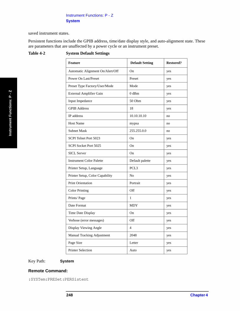
Instrument Functions: P - ZSystem
Inst
rum
ent F
unct
ions
: P -
Z
saved instrument states.
Persistent functions include the GPIB address, time/date display style, and auto-alignment state. These are parameters that are unaffected by a power cycle or an instrument preset.
Key Path: System
Remote Command:
:SYSTem:PRESet:PERSistent
Table 4-2 System Default Settings
Feature Default Setting Restored?
Automatic Alignment On/Alert/Off On yes
Power On Last/Preset Preset yes
Preset Type Factory/User/Mode Mode yes
External Amplifier Gain 0 dBm yes
Input Impedance 50 Ohm yes
GPIB Address 18 yes
IP address 10.10.10.10 no
Host Name mypsa no
Subnet Mask 255.255.0.0 no
SCPI Telnet Port 5023 On yes
SCPI Socket Port 5025 On yes
SICL Server On yes
Instrument Color Palette Default palette yes
Printer Setup, Language PCL3 yes
Printer Setup, Color Capability No yes
Print Orientation Portrait yes
Color Printing Off yes
Prints/ Page 1 yes
Date Format MDY yes
Time Date Display On yes
Verbose (error messages) Off yes
Display Viewing Angle 4 yes
Manual Tracking Adjustment 2048 yes
Page Size Letter yes
Printer Selection Auto yes
248 Chapter 4
Instrument Functions: P - ZSystem
Instrument Functions: P - Z
Example: SYST:PRES:PERS
4.9.12 Licensing
Accesses the security system to enable licensing for individual options. You can install measurement mode personality options in an instrument at any time (unless Option 117 is enabled; refer to the Getting Started Guide, Chapter 1 “Turning on the Analyzer for the First Time”). After you load the personality mode into memory, you must enter a license key to allow access to the option.
For information on how to use this system, see the installation information for individual options in the measurement personalities’ user’s guides.
NOTE Not all options can be enabled using this system and there is no way to turn off an option through this system. Once an option has been licensed for a given analyzer, it cannot be transferred to a different analyzer.
Key Path: System
Remote Command:
There is no remote command for this key.
4.9.12.1 Option
Activates the alpha editor enabling you to enter the designation for the option to be installed. An option is a three character string that specifies the option or application that is to be installed, as found in the catalog. To terminate the entry, press Enter or Return. An external keyboard may also be used for this entry. The option number appears on the second line of the Option key.
Key Path: System, Licensing
State Saved: Not saved in Instrument State.
SCPI Status Bits/ OPC Dependencies: None
Remote Command:
See “License Key” on page 249
Example: SYST:LKEY “B78”, “B62A35B37679”
SYST:LKEY? “B78”
4.9.12.2 License Key
Activates the alpha editor to allow you to enter the license key number for the option to be installed. The license key number is a hexadecimal number that requires entry of both letters and numbers. Use the front-panel numeric keyboard to enter numerical values. You will see your entry in the active function area. A license key is a 12-character hexadecimal string given with the option. The license key is unique to a specific option installed and instrument host ID. To terminate the entry, press Enter or Return. An external keyboard may also be used for this entry. The license key number will appear on the second line of the License Key menu key.
Chapter 4 249
Instrument Functions: P - ZSystem
Inst
rum
ent F
unct
ions
: P -
Z
Key Path: System, Licensing
Dependencies/ Couplings: None
State Saved: Not saved in Instrument State.
SCPI Status Bits/ OPC Dependencies: None
Factory Preset: Clears the current value.
Remote Command:
:SYSTem:LKEY <“option”>, <“license key”>
:SYSTem:LKEY? <“option”>
Remote Command Notes: The query returns a string that contains the license key for a specified application or option that is already installed in the instrument. The license key will also be returned if the application is not currently in memory, but had been installed at some previous time. The license key is unique to a specific option, host ID and serial number. Host ID can be returned by :SYSTem:HID?.
Example: SYST:LKEY “B78”, “B62A35B37679”
SYST:LKEY? “B78”
The query would return “B62A35B37679”
If the instrument does not have a license key for that option, the query would return ““.
250 Chapter 4
Instrument Functions: P - ZSystem
Instrument Functions: P - Z
4.9.12.3 Activate License
Activates the specified option. When a valid option key number and license key number have been entered, press Activate. If your entry was correct, the option will be enabled and the message: Option activated will appear in the status line of your display. The option number and license key number will also be cleared from the License Key and Option key.
If your entry was incorrect, the error message: License key invalid will appear in the status line of your display. The option number and license key number can be edited until they are correct.
NOTE It is possible to enable an option for which the analyzer is not yet configured. Therefore, the message Option activated does not mean that the option will immediately function. For a display of options that are enabled and for which the analyzer is properly configured, press System, More, Show System.
Key Path: System, Licensing
Remote Command:
There is no remote command for this key.
4.9.12.4 Delete License
Deletes the license key from memory, however, the option firmware is not deleted. The instrument must be rebooted before the option is removed.
Key Path: System, Licensing
Remote Command:
:SYSTem:LKEY:DELete <‘application option’>
Example: SYST:LKEY:DEL “BAC”
4.9.12.5 Show License
Displays the number and description of the licenses installed in your instrument.
Key Path: System, Licensing
Annunciation/ Annotation: Text Screen
Dependencies/ Couplings: The active function is disabled.
Remote Command:
There is no remote command for this function.
Chapter 4 251
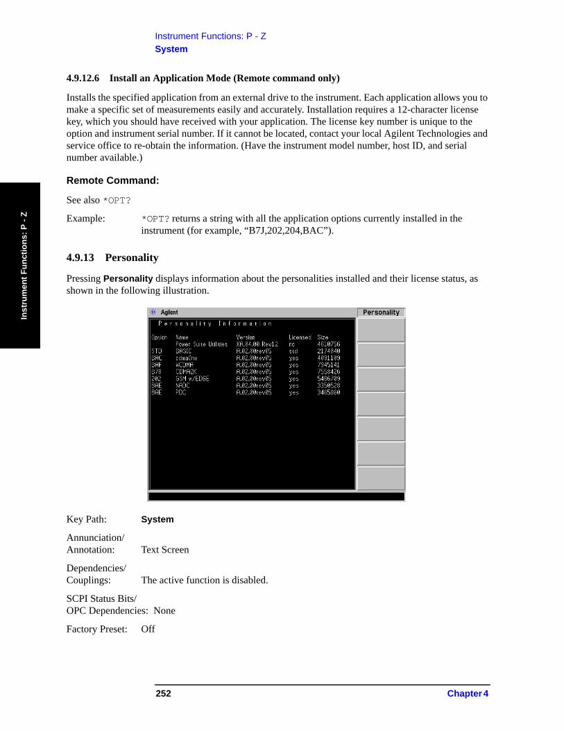
Instrument Functions: P - ZSystem
Inst
rum
ent F
unct
ions
: P -
Z
4.9.12.6 Install an Application Mode (Remote command only)
Installs the specified application from an external drive to the instrument. Each application allows you to make a specific set of measurements easily and accurately. Installation requires a 12-character license key, which you should have received with your application. The license key number is unique to the option and instrument serial number. If it cannot be located, contact your local Agilent Technologies and service office to re-obtain the information. (Have the instrument model number, host ID, and serial number available.)
Remote Command:
See also *OPT?
Example: *OPT? returns a string with all the application options currently installed in the instrument (for example, “B7J,202,204,BAC”).
4.9.13 Personality
Pressing Personality displays information about the personalities installed and their license status, as shown in the following illustration.
Key Path: System
Annunciation/ Annotation: Text Screen
Dependencies/ Couplings: The active function is disabled.
SCPI Status Bits/ OPC Dependencies: None
Factory Preset: Off
252 Chapter 4
Instrument Functions: P - ZSystem
Instrument Functions: P - Z
4.9.14 Security
Pressing Security brings up the Security menu.
Key Path: System
Dependencies/ Couplings: The active function is disabled.
Remote Command:
There is no remote command for this key.
History: Added with firmware revision A.09.00.
4.9.14.1 Secure Erase All
Erases all persistent storage in the instrument. When pressed, the PSA will display the following message: “This key will delete all data and firmware in the instrument. You will need to reinstall firmware after executing this operation. Press the key again if you wish to proceed.” Thus, this key requires two presses to select the function. Upon the second press, the instrument displays the following message: “Please Confirm Erase Operation. Press Yes to erase all data and firmware from the instrument. Press No to cancel the operation.” Refer to “Managing Security” on page 255.
Key Path: System, Security
Dependencies/ Couplings: None
SCPI Status Bits/ OPC Dependencies: None
Remote Command:
:SYSTem:SECurity:CLEAr
Remote Command Notes: This command blocks the parser until the command is completed. Since this command also causes the instrument firmware to be turned off, no further communication with the instrument will be possible.
Example: SYST:SEC:CLEA
History: Added with firmware revision A.09.00.
Chapter 4 253
Instrument Functions: P - ZSystem
Inst
rum
ent F
unct
ions
: P -
Z
4.9.14.2 Secure Erase User
This key is only active if Option 117 is licensed. Erases the compact Flash on the USB/Compact Flash Interface board. This includes all saved states and traces. When this key is pressed, the instrument displays the following message: “This key will reformat the C:drive and erase all user data from the instrument. You will lose all saved states and traces. Press the key again if you wish to proceed.” Thus, this key requires two presses to select the function. Upon the second press, the instrument displays the following message: “Please Confirm Erase Operation. Press Yes to reformat C: and erase all saved states and traces. Press No to cancel the operation.”
Key Path: System, Security
Dependencies/ Couplings: Requires Option 117 to be installed and licensed.
SCPI Status Bits/ OPC Dependencies: None
Remote Command:
:SYSTem:SECurity:IMMediate
Remote Command Notes: This command blocks the parser until the command is completed.
Example: SYST:SEC:IMM
History: Added with firmware revision A.09.00.
4.9.14.3 Security
This key controls whether the instrument is currently in its secure mode or not. When Security is On, the instrument cannot write to any location on the main Flash memory. When Security is Off, the main Flash memory can be written to. When Security is in the Enabled mode, the instrument is configured to turn on the security mode upon the next power-on cycle.
If you ordered Option 117, the Secure Memory Erase option was loaded into the memory of your instrument and licensed at the factory but not enabled.
IMPORTANT DO NOT enable Option 117 until you have configured your instrument’s LAN settings (IP Address, Subnet Mask, Host Name, Gateway, [System, Config IO], and added or removed options and licenses).
After the security mode is enabled, the main Flash memory becomes read-only, rather than read/write memory. This makes it impossible to add or remove personalities or their license keys, or otherwise change the instrument’s configuration, unless you do a firmware upgrade or the System, Security, Secure Erase All procedure. This procedure will render the instrument inoperable. You will then need to run the upgrade procedure (on the Agilent Web site) to reinstall the firmware and completely reconfigure your instrument. After reinstalling the firmware, Security will be disabled. Refer to “Managing Security” on page 255 in this chapter.
When you are totally satisfied with the configuration of your analyzer, enable the Secure Memory Erase
254 Chapter 4
Instrument Functions: P - ZSystem
Instrument Functions: P - Z
option by pressing System, Security, Security Enabled. The security mode will then be enabled the next time the analyzer’s power is cycled.
Key Path: System, Security, Security
Dependencies/ Couplings: None Active
SCPI Status Bits/ OPC Dependencies: None
Remote Command:
:SYSTem:SECurity:ENABle ON|OFF
:SYSTem:SECurity:ENABle?
Remote Command Notes: This command allows the security state to be set and queried from a SCPI port. Note that the command sets security to the “enabled” mode, which will turn on the security mode at the next power-on cycle. When the parameter is OFF, the security mode will be set to off only if the current security mode is “enabled” or “off.” If the security mode is on, this command has no effect. The query form of the command always returns the current state of the security mode (ON, OFF, or ENAB).
Example: SYST:SEC:ENAB ON
History: Added with firmware revision A.09.00.
4.9.15 Managing Security
4.9.15.1 Secure Erase All Function
CAUTION Secure Erase All will render the instrument inoperable. All instrument settings under System, Config I/O, such as the LAN address or gateway address will be lost. All instrument option License Keys, such as those that enable the optional preamplifier or measurement personalities, will be lost.
The following procedure outlines how to prepare prior to executing Secure Erase All, and how to recover the instrument following the Secure Erase All.
Be sure to back up the instrument configuration and option keyword information via LAN using the PSA Series Firmware Upgrade Program before the instrument is placed in the secure area.
Chapter 4 255
Instrument Functions: P - ZSystem
Inst
rum
ent F
unct
ions
: P -
Z
4.9.15.2 Preliminary Procedure (Non-secure Area)
Perform this procedure once on each spectrum analyzer prior to placing it into a secure area, and every time the instrument has been calibrated or repaired.
1. Record the Ethernet Number of the instrument. Press System, More, Show System. The Ethernet Number is a 12-digit alphanumeric string with a hyphen between the first and last set of six characters; for example, 001083-b80c55. Having this number recorded will save time when you re-install the firmware into the instrument using the “Re-installation of Firmware Procedure.”
2. Record the IP Address of the instrument. Press System, Config I/O. This address may be changed by someone using the instrument in the secure environment, but at least you will have documented what it was.
3. Obtain a list of the License Keys by saving a screen capture of the instrument’s Licensing screen. Even though the next section tells you how to backup these keywords to a PC, the PC may not be available when you need it. Press System, More, More, Licensing, Show License. Use the file manager to save an image of the screen to a formatted disk. Insert the disk in the front panel disk drive and press File, Save, Type, Screen, Format, Bitmap and select Directory A. Press Save Now. The file can be displayed or printed from any application capable of reading bitmap (.bmp) files. Before proceeding, verify that the screen capture of the License Keys has been properly saved to the disk by opening the file using a PC.
The licensing information can also be printed if the analyzer is connected to a printer. As a last resort, write down the Option number and License Key for each option.
Properly store the License Key data, since it will be needed to recover the instrument.
4.9.15.3 Backing-up Configuration and Option License Keys to a PC (Non-secure Area)
1. Load the PSA Series Firmware Update Program from the following Agilent Web site:http://www.agilent.com/find/psa_firmware. Click on the firmware update PSA A.xx.xx.exe link.
2. Begin the PSA firmware upgrade procedure. Accept the licensing agreement. When prompted for an instrument IP address, enter the instrument’s IP address.
3. Allow the configuration files to be saved to the default location on the PC.4. The analyzer’s user data, options, and license keys are saved in a file named ‘Config’ under a
directory that begins with the model number, followed by the serial number, then a date and time stamp on the C: drive of the PC; for example, “C:\E4448A\US42070187\15-Oct-02-11-29-AM\Config.”Make note of the path name. This file will be used to restore the analyzer’s configuration and License Keys after Secure Erase All has been used to erase its memory.
5. When the screen regarding loading the operating system and options appears, exit the firmware upgrade process. At this point, you have saved the configuration files (including the License Keys). You do not need to continue with the actual firmware download.
256 Chapter 4
Instrument Functions: P - ZSystem
Instrument Functions: P - Z
4.9.15.4 Security Clearing Procedure (Secure Area)
On the analyzer, press System, More, More, Security, Secure Erase All and confirm.
4.9.15.5 Re-installation of Firmware Procedure (Non-secure Area)
1. Load the PSA Series Firmware Update Program from the following Agilent Web site:
http://www.agilent.com/find/psa_firmware
2. At the menu screen, click on Troubleshooting Wizard, click on Recovery, then click Next.
3. Under “The PC Update Program was Interrupted,” click Next. The “Non-Functional Instrument Procedure” will appear. Follow this procedure.
NOTE The Ethernet Number saved in the “Preliminary Procedure (Non-secure Area)” on page 256 becomes the hardware address when the hyphen is removed (i.e, Ethernet Number 001083-b80c55 becomes hardware address 001083b80c55). If you have access to this previously saved address, enabling the external keyboard step in the procedure can be skipped.
NOTE Enter the path for “Restore the Configuration and User Data” when prompted. (This path was noted in “Backing-up Configuration and Option License Keys to a PC (Non-secure Area)” on page 256.)
NOTE If a configuration back-up file is not available, obtain the License Key information saved in the “Preliminary Procedure (Non-secure Area)” on page 256. The option numbers listed in the License Key information allow you to determine which options were previously loaded in the instrument and allow you to check the appropriate boxes in the update program. The actual License Keys are needed to enable the options once the firmware is re-installed.
Chapter 4 257
Instrument Functions: P - ZSystem
Inst
rum
ent F
unct
ions
: P -
Z
4.9.16 Service
These functions are used only for servicing the analyzer. A password is required to access them. Refer to the Service Guide for more information.
Key Path: System
4.9.17 Keyboard Lock (Remote Command Only)
Disables the instrument keyboard to prevent local input when the instrument is controlled remotely. An annunciator reading “Klock” alerts the local user that the keyboard is locked. Or you can display a system message using SYSTem:MESSage.
History: Added with firmware revision A.03.00
Remote Command:
:SYSTem:KLOCK?
Example: SYST:KLOCK?
4.9.18 Remote Message
Enables a remote user to send a message that will appear in the Status Bar at bottom of the instrument display. The new message will overwrite any previous message. The message will remain until removed by use of :SYSTem:MESSage:OFF.
Example: :SYSTem:MESSage "Instrument currently in use remotely by Ted in R+D"
Remarks: The message appears as green text against a black background, to differentiate it from internally generated messages, which appear as white text against a black background.
The SYSTem:KLOCk command locks out the front-panel keys.
History: Added with firmware revision A.03.00
Remote Command:
:SYSTem:MESSage <string>
Example: :SYSTem:MESSage "Instrument currently in use remotely by Tom"
258 Chapter 4
Instrument Functions: P - ZSystem
Instrument Functions: P - Z
4.9.19 Remote Message Turned Off
Removes any system message from the Status Bar at the bottom of the instrument display. A message can be displayed using the :SYSTem:MESSage command.
History: Added with firmware revision A.03.00
Remote Command:
:SYSTem:MESSage:OFF
Example: SYST:MESS:OFF
4.9.20 Power On Elapsed Time (Remote Command Only)
Returns the number of seconds that have elapsed since the instrument was turned on for the very first time.
Remote Command:
:SYSTem:PON:ETIMe?
Example: SYST:PON:ETIM?
4.9.21 SCPI Version Query (Remote Command Only)
Returns the SCPI version number with which the instrument complies. The SCPI industry standard changes regularly. This command indicates the version used when creating the instrument SCPI commands.
Remote Command:
:SYSTem:VERSion?
Example: SYST:VERS?
Chapter 4 259

Instrument Functions: P - ZSystem
Inst
rum
ent F
unct
ions
: P -
Z
260 Chapter 4
Instrument Functions: P - ZTrace/View
Instrument Functions: P - Z
4.10 Trace/View Displays menu keys that enable you to set how trace information is stored and displayed. Each trace is comprised of a series of data points in which x and y axis information is stored. The analyzer updates the information for the active trace with each sweep.
NOTE If you have selected ACP, Burst Power, Channel Power, Harmonic Distortion, Multi-Carrier Power, Power Stat CCDF, or Spectrum Emission Mask in the MEASURE menu, refer to the Trace/View sections specific to those measurements in Volume 2, One-Button Measurements User’s and Programmer’s Reference.
Key Path: Front-panel key
Factory Default: Trace 1: Clear Write
Trace 2: Blank
Trace 3: Blank
Remote Command:
:TRACe[1]|2|3:MODE WRITe|MAXHold|MINHold|VIEW|BLANk
WRITe = Clear Write
MAXHold = Max Hold
MINHold = Min Hold
VIEW = View
BLANk = Blank
:TRACe[1]|2|3:MODE?
Example: TRAC:MODE WRIT
TRAC:MODE MAXH
TRAC:MODE MINH
TRAC:MODE VIEW
TRAC:MODE BLANk
TRAC:MODE?
Chapter 4 261
Instrument Functions: P - ZTrace/View
Inst
rum
ent F
unct
ions
: P -
Z
4.10.1 Send/Query Trace Data (Remote Command Only)
This command allows trace data to be sent to the analyzer or queried from the analyzer. The response to the query is a list of the amplitude points that comprise the requested trace in the current Y-axis unit of the analyzer. The X-axis unit is that of the destination trace for send and the source trace for the query.
The number of trace points sent or returned is set by [:SENSE]:SWE:POIN (from 101 to 8192).
Factory Preset: Real,32 for Spectrum Analysis mode
History: Changed with firmware revision A.08.00.
Remote Command:
:TRACe[:DATA] TRACE1 | TRACE2 | TRACE3 | TRACE4 | TRACE5 | TRACE6, <definite_length_block> | <comma_separated_ASCII_data>
:TRACe[:DATA]? TRACE1 | TRACE2 | TRACE3 | TRACE4 | TRACE5 | TRACE6
Remote Command Notes: The data format set by FORMat:DATA and FORMat:BORDer is used both for sending data to the instrument and receiving data from the instrument.
The FORMat:DATA command describes the different types of data formats that can be used with trace data. See “Format Numeric Data (Remote Command Only)” on page 128.
Use the FORMat:BORDer command to set the byte order. See “Set Data Byte Order (Remote Command Only)” on page 128.
Commands :MMEM:STOR:TRAC and :MMEM:LOAD:TRAC are used to transfer trace data to/from the internal hard drive or floppy drive of the instrument. See “Save Now” on page 112 and “Load Now” on page 117.)
When sending data to the instrument, the data block must contain exactly the number of points currently specified in Sweep, Points or the error “Invalid list data” will be generated and there will be no change to the target trace.
No units terminator (for example, dB or V) is used when sending data; the data is taken as being in the current Y-axis unit of the analyzer.
When a trace is sent to the instrument, it immediately overwrites all of the data in the target trace, even if that trace is in View, or if it is active and in the middle of a sweep.
NOTE Do not send a trace to the instrument or query trace data until Average or Max/Min Hold operations have been completed, or data will be misrepresented. It is generally advisable to be in Single Sweep, View or Blank when sending trace data to the analyzer or querying trace data from the analyzer.
If in the middle of a set of Average or Max/Min Hold operations, it can seriously invalidate the result, so you should exercise caution. Similarly, when querying trace data, it is best if the analyzer is not sweeping during the query. Therefore, it is generally advisable to be in Single Sweep, View or Blank when sending trace data to the analyzer or querying trace data from the analyzer.
262 Chapter 4
Instrument Functions: P - ZTrace/View
Instrument Functions: P - Z
Example: TRAC TRACE1,-1,-2,-3,-4,-5 sends five points to trace 1. Assuming that FORMat:DATA is set to ASCII, Y-axis unit is set to dBm, and Sweep, Points is set to 5, this will result in trace 1 consisting of the five points: −1 dBm, −2 dBm, −3 dBm, −4 dBm, and −5 dBm.
TRAC? TRACE2 queries the analyzer for the contents of trace 2.
4.10.2 Trace
Determines which trace the menu keys will affect. Press Trace until the number of the desired trace is underlined.
Key Path: Trace/View
State Saved: Saved in Instrument State for all traces
Factory Preset: Trace 1 is active
Factory Default: Trace 1 is active
History: Added with firmware revision A.02.00
Remote Command:
There is no remote command for this function.
4.10.3 Clear Write
Erases any data previously stored in the selected trace and continuously displays signals during the sweep of the analyzer.
Key Path: Trace/View
Remote Command:
See “Trace/View” on page 261.
Example: TRAC:MODE WRIT
Chapter 4 263
Instrument Functions: P - ZTrace/View
Inst
rum
ent F
unct
ions
: P -
Z
4.10.4 Max Hold
Maintains the maximum level for each trace point of the selected trace (1, 2 or 3), and updates each trace point if a new maximum level is detected in successive sweeps.
NOTE Pressing Restart, changing the vertical scale (Amplitude, Scale Type, Log or Lin) or turning averaging on (BW/Avg, Average (On)) restarts the held trace.
Key Path: Trace/View
Remote Command:
See “Trace/View” on page 261.
Example: TRAC:MODE MAXH
4.10.5 Min Hold
Maintains the minimum level for each trace point of the selected trace (1, 2 or 3), and updates each trace point if a new minimum level is detected in successive sweeps.
NOTE Pressing Restart, changing the vertical scale (Amplitude, Scale Type, Log or Lin) or turning averaging on (BW/Avg, Average (On)) restarts the held trace.
Key Path: Trace/View
History: Added with firmware revision A.02.00
Remote Command:
See “Trace/View” on page 261.
Example: TRAC:MODE MINH
4.10.6 View
Holds and displays the amplitude data of the selected trace. The trace is not updated as the analyzer sweeps.
Key Path: Trace/View, Trace
History: Added with firmware revision A.02.00
Remote Command:
See “Trace/View” on page 261.
Example: TRAC:MODE VIEW
264 Chapter 4
Instrument Functions: P - ZTrace/View
Instrument Functions: P - Z
4.10.7 Blank
Stores the amplitude data for the selected trace and removes it from the display. The selected trace register is not updated as the analyzer sweeps.
Key Path: Trace/View
History: Added with firmware revision A.02.00
Remote Command:
See “Trace/View” on page 261.
Example: TRAC:MODE BLAN
4.10.8 Operations
This menu allows the user to do simple trace operations.
Key Path: Trace/View
History: Added with firmware revision A.08.00
4.10.8.1 1 <-> 2
Exchanges the contents of trace 1 with the contents of trace 2 and puts both in view mode. The action is performed once. It is not available for continuous sweeps. To clear any trace operation, set the trace back to Clear Write, Max Hold, or Min Hold.
The X-Axis settings and domain of a trace stay with it when it is copied or exchanged.
Key Path: Trace/View, Operations
History: Added with firmware revision A.08.00
Remote Command:
:TRACe:EXCHange: <trace_name>, <trace_name>
Example: TRAC:EXCH TRACE1,TRACE2
4.10.8.2 2 – DL -> 2
Subtracts the display line from trace 2 and places the result in trace 2. The action is performed once. It is not available for continuous sweeps. To keep the modified trace 2 from changing after the operation, it is set to View. To clear any trace operation, set the trace back to Clear Write, Max Hold, or Min Hold.
Key Path: Trace/View, Operations
History: Added with firmware revision A.08.00
Remote Command:
:TRACe:MATH:SUBTract:DLIN <trace_name>
Example: TRAC:MATH:SUBT:DLIN TRACE2
Chapter 4 265
Instrument Functions: P - ZTrace/View
Inst
rum
ent F
unct
ions
: P -
Z
4.10.8.2.1 2 <-> 3
Exchanges the contents of trace 2 with the contents of trace 3 and puts both in view mode. The action is performed once. It is not available for continuous sweeps. To keep the modified traces from changing after the operation, they are set to View. To clear any trace operation, set the trace back to Clear Write, Max Hold, or Min Hold.
The X-Axis settings and domain of a trace stay with it when it is copied or exchanged.
Key Path: Trace/View, Operations
History: Added with firmware revision A.08.00
Remote Command:
:TRACe:EXCHange: <trace_name>, <trace_name>
Example: TRAC:EXCH TRACE2,TRACE3
4.10.8.2.2 1 -> 3
Copies the contents of trace 1 into the contents of trace 3 and puts trace 3 in blank mode. The action is performed once. It is not available for continuous sweeps. To clear any trace operation, set the trace back to Clear Write, Max Hold, or Min Hold.
The X-Axis settings and domain of a trace stay with it when it is copied or exchanged.
Key Path: Trace/View, Operations
History: Added with firmware revision A.08.00
Remote Command:
:TRACe:COPY <src_trace>,<dest_trace>
Example: TRAC:COPY TRACE1,TRACE3
4.10.8.2.3 2 -> 3
Copies the contents of trace 2 into the contents of trace 3 and puts trace 3 in blank mode. The action is performed once. It is not available for continuous sweeps. To clear any trace operation, set the trace back to Clear Write, Max Hold, or Min Hold.
The X-Axis settings and domain of a trace stay with it when it is copied or exchanged.
Key Path: Trace/View, Operations
History: Added with firmware revision A.08.00
Remote Command:
:TRACe:COPY <src_trace>,<dest_trace>
Example: TRAC:COPY TRACE2,TRACE3
4.10.8.2.4 Trace Addition (Remote Command Only)
This command adds the contents of any two traces, and puts the sum in any trace. The action is
266 Chapter 4
Instrument Functions: P - ZTrace/View
Instrument Functions: P - Z
performed once. It is not available for continuous sweeps. All traces that are modified are set to View. To clear any trace operations, set the trace back to Clear Write, Max Hold, or Min Hold.
History: Added with firmware revision A.08.00
Remote Command:
:TRACe:MATH:ADD <dest_trace>,<src_trace>,<src_trace>
Example: TRAC:MATH:ADD TRACE2,TRACE1,TRACE3
This command will add TRACE1 to TRACE3 and store it in TRACE2
4.10.8.2.5 Trace Subtraction (Remote Command Only)
This command adds the contents of any two traces, and puts the remainder in any trace. The action is performed once. It is not available for continuous sweeps. All traces modified are set to View. To clear any trace operation, set the trace back to Clear Write, Max Hold, or Min Hold.
History: Added with firmware revision A.08.00
Remote Command:
:TRACe:MATH:SUBTract <dest_trace>,<src_trace>,<src_trace>
Example: TRAC:MATH:SUB TRACE2,TRACE1,TRACE3
This command will subtract TRACE3 from TRACE1 and store it in TRACE2
4.10.8.2.6 Trace Mean (Remote Command Only)
This command finds the mean of the amplitude of all the points on a trace and is returned as a single value in the current amplitude units.
History: Added with firmware revision A.08.00
Remote Command:
:TRACe:MATH:MEAN? <src_trace>
Example: TRAC:MATH:MEAN TRACE2
4.10.8.3 Normalize
Displays menu keys that enable you to normalize trace data.
Key Path: Trace/View
History: Added with firmware revision A.08.00
Chapter 4 267
Instrument Functions: P - ZTrace/View
Inst
rum
ent F
unct
ions
: P -
Z
4.10.8.3.1 Store Ref (1 −> 3)
Copies trace 1 into trace 3. Store Ref (1 −> 3) must be pressed before pressing Normalize (On). This puts trace 3 in view mode.
Key Path: Trace/View, Normalize
History: Added with firmware revision A.08.00
Remote Command:
There is no remote command for this function, however the trace copy command can be used for this purpose.
Example: TRAC:COPY TRACE1,TRACE3
4.10.8.3.2 Normalize On/Off
Normalize (On) activates the normalize function. On each sweep, the normalized trace (trace 1) is subtracted from trace 3 and the result is added to the normalized reference level. The display shows the result of the following calculation in trace 1. This determines the location of the trace on the display, not the marker reading.
Trace 1 – Reference Trace − Normalized Reference Level
where trace 1 and the reference trace are in absolute units and the reference level is in relative units.
The new trace 1 is normalized with respect to the normalized reference level and reference trace, even if the values of the normalized reference level or reference are changed. This function remains in effect on all subsequent sweeps until it is turned off.
The normalize function is most useful for applying correction data to a trace while making a stimulus-response measurement with a tracking source. For example, connect the cables and a through line in place of the device to be measured (between the tracking source and the analyzer input). Notice that the frequency response is not perfectly flat, showing the response of the cables, as well as the flatness of both the tracking generator and the analyzer. Now press Store Ref (1 -> 3), Normalize On. Notice that the displayed trace is now flat, or normalized. The position of the normalized trace can now be moved to a different position on the display by changing the normalized reference position. This may be useful if the device to be tested has positive gain, such as an amplifier. Now replace the through line with the device under test, and an accurate measurement of the gain or loss can be made.
Key Path: Trace/View, Normalize
Dependencies/Couplings:
• When Normalize is turned on, Volts, Watts, Amps, and Scale Type are not available.
• If Scale Type is Linear, Normalize is not available.
State Saved: Saved in Instrument State.
Factory Preset: Off
History: Added with firmware revision A.08.00
268 Chapter 4
Instrument Functions: P - ZTrace/View
Instrument Functions: P - Z
Remote Command:
:CALCulate:NTData[:STATe] OFF|ON|0|1
:CALCulate:NTData[:STATe]?
Example: CALC:NTD ON
CALC:NTD?
4.10.8.3.3 Norm Ref Lvl
Sets the level (in dB) of the normalized reference.
Key Path: Trace/View, Normalize
Factory Default: 0 dB
State Saved: Saved in Instrument State.
Knob Increment: 0.1 dB
Step Key Increment: 10 dB
Range: −327.6 dB to +327.6 dB
History: Added with firmware revision A.08.00
Remote Command
:DISPlay:WINDow:TRACe:Y[:SCALe]:NRLevel <rel_ampl>
:DISPlay:WINDow:TRACe:Y[:SCALe]:NRLevel?
Example: DISP:WIND:TRAC:Y:NRL .10 dB
DISP:WIND:TRAC:Y:NRL?
4.10.8.3.4 Norm Ref Posn
Offsets the displayed trace without affecting the instrument gain or attenuation settings. This allows the displayed trace to be moved without decreasing measurement accuracy. The normalized reference position is indicated with a (>) character on the left side of the display and a (<) character on the right side of the display, just inside the graticule.
Key Path: Trace/View, Normalize
State Saved: Saved in Instrument State.
Factory Preset: 10
Factory Default 10
Range: 0 to 10
Knob Increment: 1
Chapter 4 269
Instrument Functions: P - ZTrace/View
Inst
rum
ent F
unct
ions
: P -
Z
Step Key Increment: 1
History: Added with firmware revision A.08.00
Remote Command:
:DISPlay:WINDow:TRACe:Y[:SCALe]:NRPosition <integer>
:DISPlay:WINDow:TRACe:Y[:SCALe]:NRPosition?
Remote Command Notes: The top and bottom graticule lines correspond to 10 and 0, respectively
Remote Command Example: DISP:WIND:TRAC:Y:NRP 5
DISP:WIND:TRAC:Y:NRP?
4.10.8.3.5 Ref Trace (Trace 3)
Views or blanks the reference trace on the display. The reference trace is trace 3, so this is the same as setting trace 3’s display attribute.
Key Path: Trace/View, Normalize
State Saved: Saved in Instrument State.
History: Added with firmware revision A.08.00
Remote Command:
Use the :TRACe:MODE command to show or blank the reference trace.
Remote Command Notes: Trace 3 is always the reference trace by definition.
Remote Command Example: TRAC3:DISP 1 shows the reference trace.
270 Chapter 4
Instrument Functions: P - ZTrig
Instrument Functions: P - Z
4.11 Trig
Displays menu keys that enable you to select the trigger mode of a sweep or measurement. When in a trigger mode other than Free Run, the analyzer will begin a sweep only with the proper trigger condition.
In FFT measurements, the trigger controls when the data is acquired for FFT conversion; see “Making Gated FFT Measurements With Your PSA” on page 58.
Key Path: Front-panel key
State Saved: Saved in Instrument State
Factory Preset: Free Run
Remote Command:
:TRIGger[:SEQuence]:SOURce IMMediate|VIDeo|LINE|EXTernal[1]|EXTernal2|RFBurst
:TRIGger[:SEQuence]:SOURce?
IMM = Free Run triggeringVID = Video – Triggers on the video signal levelLINE = Line – Triggers on the power line signalExt1 = External Front – Enables you to trigger on an externally connected trigger sourceExt2 = External Rear – Enables you to trigger on an externally connected trigger source
Remote Command Notes: Other trigger-related commands are found in the INITiate and ABORt subsystems.
Example: TRIG:SOUR VID
4.11.1 Free Run
Sets the trigger to start a new sweep/measurement as soon as the last one has ended (continuous sweep mode) or immediately (single sweep mode).
Key Path: Trig
Dependencies/ Couplings: Trigger Slope and Delay adjustments are not available with Free Run triggering.
Remote Command:
See “Trig” on page 271
Example: TRIG:SOUR IMM
Chapter 4 271
Instrument Functions: P - ZTrig
Inst
rum
ent F
unct
ions
: P -
Z
4.11.2 Video
Activates the trigger condition that allows the next sweep to start if the detected RF envelope voltage crosses a level set by the video trigger level. When Video is pressed, a line appears on the display. The analyzer triggers when the input signal exceeds the trigger level at the left edge of the display. You can change the trigger level using the step keys, the knob, or the numeric keypad. The line remains as long as video trigger is the trigger type.
Key Path:. Trig
Dependencies/Couplings:. Trigger Delay adjustment is not available with Video triggering.
Video triggering is not available when the detector type is Average. Marker Functions that set the detector to average (such as Marker Noise or Band/Intvl Power) are not available when the video trigger is on.
This function is not available when the Resolution Bandwidth is less than 1 kHz. If a Resolution Bandwidth less than 1 kHz is selected while in Video Trigger mode, the Trigger mode changes to Free Run.
Factory Preset:. –25 dBm
Range:. Using logarithmic scale: from 10 display divisions below the reference level, up to the reference level
Using linear scale: from 100 dB below the reference level, up to the reference level
For more information, see “Scale Type” on page 38.
Remote Command:
See “Trig” on page 271 for the command that sets trigger mode. The following commands set or read the trigger level.
:TRIGger[:SEQuence]:VIDeo:LEVel <ampl>
:TRIGger[:SEQuence]:VIDeo:LEVel?
:TRIGger[:SEQuence]:VIDeo:LEVel:FREQuency <freq> sets the Video Trigger level when in FM Demod, and Demod View is on
:TRIGger[:SEQuence]:VIDeo:LEVel:FREQuency?
Example: . TRIG:SOUR VID selects video triggering.
4.11.3 Line
Sets the trigger to start a new sweep or measurement to be synchronized with the next cycle of the line voltage.
Key Path: Trig
Couplings/ Dependencies: Line trigger is not available when operating from a dc power source.
Remote Command:
See “Trig” on page 271
272 Chapter 4
Instrument Functions: P - ZTrig
Instrument Functions: P - Z
Example: TRIG:SOUR LINE selects line triggering.
4.11.4 Ext Front (Ext Trig In)
Sets the trigger to start a new sweep or measurement whenever the external voltage (connected to EXT TRIGGER INPUT on the front panel) passes through approximately 1.5 volts.
Key Path: Trig
State Saved: Saved in Instrument State
Factory Preset: 1.5 V
Remote Command:
See “Trig” on page 271
Example: TRIG:SOUR EXT to select front panel external triggering.
4.11.5 Ext Rear (Trigger In)
Sets the trigger to start a new sweep or measurement whenever the external voltage (connected to TRIGGER IN on the rear panel) passes through approximately 1.5 volts.
Key Path: Trig
State Saved: Saved in Instrument State
Factory Preset: 1.5 V
Remote Command:
See “Trig” on page 271
Example: TRIG:SOUR EXT2 to select rear panel external triggering.
4.11.6 RF Burst (Wideband)
Allows the analyzer to be triggered by an RF burst envelope signal.
Key Path: Trig
Remote Command:
See “Trig” on page 271
Example: TRIG:SOUR RFB
4.11.7 Trig Slope
Controls the trigger polarity. Set to positive to trigger on a rising edge. Set to negative to trigger on a falling edge.
Chapter 4 273

Instrument Functions: P - ZTrig
Inst
rum
ent F
unct
ions
: P -
Z
Key Path: Trig
Dependencies/ Couplings: Not available for Free Run.
State Saved: Saved in Instrument State.
Factory Preset: Positive (rising edge)
Remote Command:
:TRIGger[:SEQuence]:SLOPe POSitive|NEGative
:TRIGger[:SEQuence]:SLOPe?
Example: TRIG:SLOP NEG
4.11.8 Trig Delay
Allows you to control a time delay during which the analyzer will wait to begin a sweep after receiving an external or line trigger signal. You can use negative delay to pre-trigger the instrument.
NOTE Trigger Delay is not available in Free Run, so turning Free Run on turns off Trigger Delay, but preserves the value of Trigger Delay.
Key Path: Trig
Dependencies/ Couplings: This function is not available when Trigger is Free Run or Video.
This function is not available when Gate is on.
State Saved: Saved in Instrument State.
Factory Preset: Off, 1 μs
Range: –150 ms to +500 ms
History: Added with firmware revision A.02.00
Remote Command:
:TRIGger[:SEQuence]:DELay <time>
:TRIGger[:SEQuence]:DELay?
:TRIGger[:SEQuence]:DELay:STATe OFF|ON|0|1
:TRIGger[:SEQuence]:DELay:STATe?
Example: TRIG:DEL:STAT ON
TRIG:DEL 100 ms
274 Chapter 4
Instrument Functions: P - ZTrig
Instrument Functions: P - Z
4.11.9 Trig Offset (Remote Command Only)
This command sets the trigger offset. Trigger offset refers to the specified time interval before or after the trigger event from which data is to be written to the trace, and then displayed. Ordinarily, the trigger offset value is zero, and trace data is displayed beginning at the trigger event. A negative trigger offset value results in the display of trace data prior to the trigger event. A positive trigger offset value results in an effective delay in the display of trace data after the trigger event.
The trigger offset value used when the feature is enabled depends on the following parameters:
• Nominal trigger offset value originally entered
• Specific instrument hardware in use
• Sweep time
• Number of sweep points
The effective trigger offset value are re-calculated whenever any of these parameters change.
State Saved: Saved in Instrument State.
Factory Preset: 0 –500 ms
Range: Hardware specific; dependent upon the ADC being used, current state and the number of sweep points.
History: Added with firmware revision A.02.00
Remote Command:
:TRIGger[:SEQuence]:OFFSet <time>
:TRIGger[:SEQuence]:OFFSet?
:TRIGger[:SEQuence]:OFFSet:STATe OFF|ON|0|1
:TRIGger[:SEQuence]:OFFSet:STATe?
Remote Command Notes: Trigger offset can only be turned on when in zero span and the resolution bandwidth is 1 kHz or greater. Trigger offset is available for all trigger modes.
Example: TRIG:OFFS 100 ms
TRIG:OFFS:STAT ON turns on the trigger offset.
Chapter 4 275

Instrument Functions: P - ZTrig
Inst
rum
ent F
unct
ions
: P -
Z
276 Chapter 4

Programm
ing Fundamentals
5 Programming Fundamentals
277
Programming FundamentalsPr
ogra
mm
ing
Fund
amen
tals
• “SCPI Language Basics” on page 279
• “Improving Measurement Speed” on page 287
• “Programming Command Compatibility Across Model Numbers and Across Modes” on page 294
• “Using the LAN to Control the Instrument” on page 302
• “Programming in C Using the VTL” on page 326
• “Overview of the GPIB Bus” on page 334
278 Chapter 5
Programming FundamentalsSCPI Language Basics
Programm
ing Fundamentals
SCPI Language BasicsThis section is not intended to teach you everything about the SCPI (Standard Commands for Programmable Instruments) programming language. The SCPI Consortium or IEEE can provide that level of detailed information.
Topics covered in this chapter include:
• “Creating Valid Commands” on page 280
• “Command Keywords and Syntax” on page 279
• “Special Characters in Commands” on page 281
• “Parameters in Commands” on page 282
• “Putting Multiple Commands on the Same Line” on page 285
For more information refer to:
IEEE Standard 488.1-1987, IEEE Standard Digital Interface for Programmable Instrumentation. New York, NY, 1998.
IEEE Standard 488.2-1987, IEEE Standard Codes, Formats, Protocols and Comment Commands for Use with ANSI/IEEE Std488.1-1987. New York, NY, 1998.
Command Keywords and Syntax
A typical command is made up of keywords set off by colons. The keywords are followed by parameters that can be followed by optional units.
Example: SENSe:FREQuency:STARt 1.5 MHZ
The instrument does not distinguish between upper and lower case letters. In the documentation, upper case letters indicate the short form of the keyword. The lower case letters, indicate the long form of the keyword. Either form may be used in the command.
Example: Sens:Freq:Star 1.5 mhz
is the same as SENSE:FREQ:start 1.5 MHz
NOTE The command SENS:FREQU:STAR is not valid because FREQU is neither the short, nor the long form of the command. Only the short and long forms of the keywords are allowed in valid commands.
Chapter 5 279
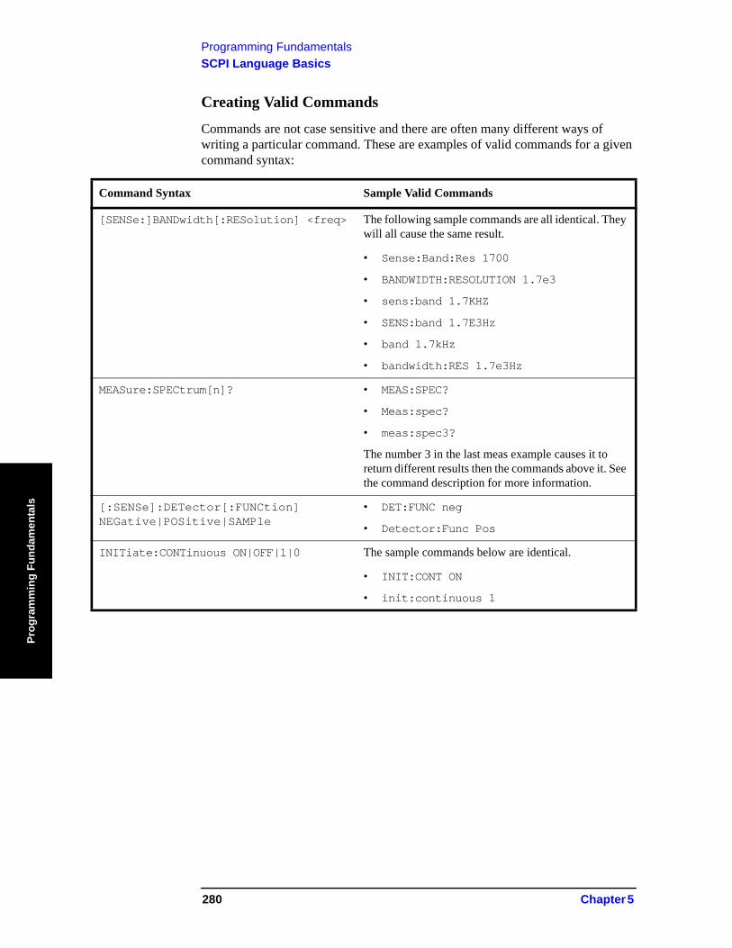
Programming FundamentalsSCPI Language Basics
Prog
ram
min
g Fu
ndam
enta
ls
Creating Valid Commands
Commands are not case sensitive and there are often many different ways of writing a particular command. These are examples of valid commands for a given command syntax:
Command Syntax Sample Valid Commands
[SENSe:]BANDwidth[:RESolution] <freq> The following sample commands are all identical. They will all cause the same result.
• Sense:Band:Res 1700
• BANDWIDTH:RESOLUTION 1.7e3
• sens:band 1.7KHZ
• SENS:band 1.7E3Hz
• band 1.7kHz
• bandwidth:RES 1.7e3Hz
MEASure:SPECtrum[n]? • MEAS:SPEC?
• Meas:spec?
• meas:spec3?
The number 3 in the last meas example causes it to return different results then the commands above it. See the command description for more information.
[:SENSe]:DETector[:FUNCtion] NEGative|POSitive|SAMPle
• DET:FUNC neg
• Detector:Func Pos
INITiate:CONTinuous ON|OFF|1|0 The sample commands below are identical.
• INIT:CONT ON
• init:continuous 1
280 Chapter 5
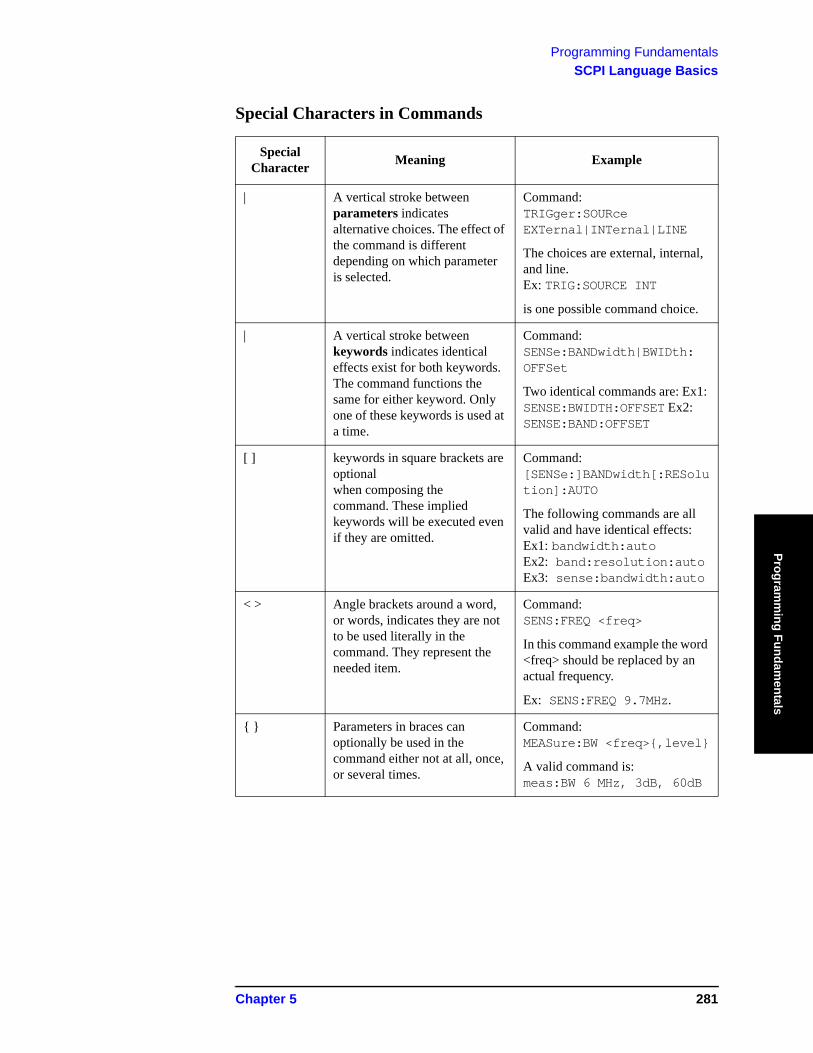
Programming FundamentalsSCPI Language Basics
Programm
ing Fundamentals
Special Characters in Commands
Special Character Meaning Example
| A vertical stroke between parameters indicates alternative choices. The effect of the command is different depending on which parameter is selected.
Command: TRIGger:SOURce EXTernal|INTernal|LINE
The choices are external, internal, and line. Ex: TRIG:SOURCE INT
is one possible command choice.
| A vertical stroke between keywords indicates identical effects exist for both keywords. The command functions the same for either keyword. Only one of these keywords is used at a time.
Command: SENSe:BANDwidth|BWIDth: OFFSet
Two identical commands are: Ex1: SENSE:BWIDTH:OFFSET Ex2: SENSE:BAND:OFFSET
[ ] keywords in square brackets are optional when composing the command. These implied keywords will be executed even if they are omitted.
Command: [SENSe:]BANDwidth[:RESolution]:AUTO
The following commands are all valid and have identical effects: Ex1: bandwidth:auto Ex2: band:resolution:auto Ex3: sense:bandwidth:auto
< > Angle brackets around a word, or words, indicates they are not to be used literally in the command. They represent the needed item.
Command: SENS:FREQ <freq>
In this command example the word <freq> should be replaced by an actual frequency.
Ex: SENS:FREQ 9.7MHz.
{ } Parameters in braces can optionally be used in the command either not at all, once, or several times.
Command: MEASure:BW <freq>{,level}
A valid command is: meas:BW 6 MHz, 3dB, 60dB
Chapter 5 281
Programming FundamentalsSCPI Language Basics
Prog
ram
min
g Fu
ndam
enta
ls
Parameters in Commands
There are four basic types of parameters: booleans, keywords, variables and arbitrary block program data.
OFF|ON|0|1 (Boolean) This is a two state boolean-type parameter. The numeric value 0
is equivalent to OFF. Any numeric value other than 0 is equivalent to ON. The numeric values of 0 or 1 are commonly used in the command instead of OFF or ON. Queries of the parameter always return a numeric value of 0 or 1.
keyword The keywords that are allowed for a particular command are defined in the command syntax description.
Units Numeric variables may include units. The valid units for a command depend on the variable type being used. See the following variable descriptions. The indicated default units will be used if no units are sent. Units can follow the numerical value with, or without, a space.
Variable A variable can be entered in exponential format as well as standard numeric format. The appropriate range of the variable and its optional units are defined in the command description.
The following keywords may also be used in commands, but not all commands allow keyword variables.
• DEFault - resets the parameter to its default value.
• UP - increments the parameter.
• DOWN - decrements the parameter.
• MINimum - sets the parameter to the smallest possible value.
• MAXimum - sets the parameter to the largest possible value.
The numeric value for the function’s MINimum, MAXimum, or DEFault can be queried by adding the keyword to the command in its query form. The keyword must be entered following the question mark.
Example query: SENSE:FREQ:CENTER? MAX
282 Chapter 5
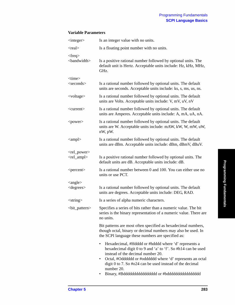
Programming FundamentalsSCPI Language Basics
Programm
ing Fundamentals
Variable Parameters
<integer> Is an integer value with no units.
<real> Is a floating point number with no units.
<freq> <bandwidth> Is a positive rational number followed by optional units. The
default unit is Hertz. Acceptable units include: Hz, kHz, MHz, GHz.
<time> <seconds> Is a rational number followed by optional units. The default
units are seconds. Acceptable units include: ks, s, ms, us, ns.
<voltage> Is a rational number followed by optional units. The default units are Volts. Acceptable units include: V, mV, uV, nV
<current> Is a rational number followed by optional units. The default units are Amperes. Acceptable units include: A, mA, uA, nA.
<power> Is a rational number followed by optional units. The default units are W. Acceptable units include: mAW, kW, W, mW, uW, nW, pW.
<ampl> Is a rational number followed by optional units. The default units are dBm. Acceptable units include: dBm, dBmV, dBuV.
<rel_power> <rel_ampl> Is a positive rational number followed by optional units. The
default units are dB. Acceptable units include: dB.
<percent> Is a rational number between 0 and 100. You can either use no units or use PCT.
<angle> <degrees> Is a rational number followed by optional units. The default
units are degrees. Acceptable units include: DEG, RAD.
<string> Is a series of alpha numeric characters.
<bit_pattern> Specifies a series of bits rather than a numeric value. The bit series is the binary representation of a numeric value. There are no units.
Bit patterns are most often specified as hexadecimal numbers, though octal, binary or decimal numbers may also be used. In the SCPI language these numbers are specified as:
• Hexadecimal, #Hdddd or #hdddd where ‘d’ represents a hexadecimal digit 0 to 9 and ‘a’ to ‘f’. So #h14 can be used instead of the decimal number 20.
• Octal, #Odddddd or #odddddd where ‘d’ represents an octal digit 0 to 7. So #o24 can be used instead of the decimal number 20.
• Binary, #Bdddddddddddddddd or #bdddddddddddddddd
Chapter 5 283
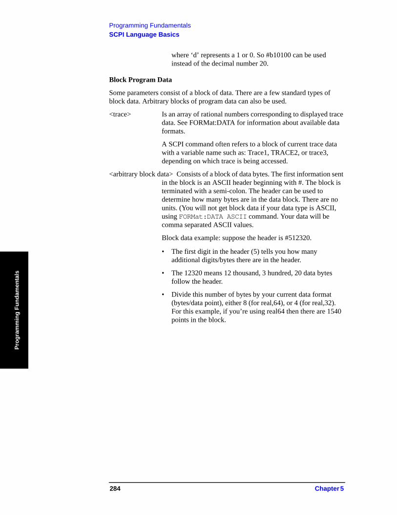
Programming FundamentalsSCPI Language Basics
Prog
ram
min
g Fu
ndam
enta
ls
where ‘d’ represents a 1 or 0. So #b10100 can be used instead of the decimal number 20.
Block Program Data
Some parameters consist of a block of data. There are a few standard types of block data. Arbitrary blocks of program data can also be used.
<trace> Is an array of rational numbers corresponding to displayed trace data. See FORMat:DATA for information about available data formats.
A SCPI command often refers to a block of current trace data with a variable name such as: Trace1, TRACE2, or trace3, depending on which trace is being accessed.
<arbitrary block data> Consists of a block of data bytes. The first information sent in the block is an ASCII header beginning with #. The block is terminated with a semi-colon. The header can be used to determine how many bytes are in the data block. There are no units. (You will not get block data if your data type is ASCII, using FORMat:DATA ASCII command. Your data will be comma separated ASCII values.
Block data example: suppose the header is #512320.
• The first digit in the header (5) tells you how many additional digits/bytes there are in the header.
• The 12320 means 12 thousand, 3 hundred, 20 data bytes follow the header.
• Divide this number of bytes by your current data format (bytes/data point), either 8 (for real,64), or 4 (for real,32). For this example, if you’re using real64 then there are 1540 points in the block.
284 Chapter 5

Programming FundamentalsSCPI Language Basics
Programm
ing Fundamentals
Putting Multiple Commands on the Same Line
Multiple commands can be written on the same line, reducing your code space requirement. To do this:
• Commands must be separated with a semicolon (;).
• If the commands are in different subsystems, the key word for the new subsystem must be preceded by a colon (:).
• If the commands are in the same subsystem, the full hierarchy of the command key words need not be included. The second command can start at the same key word level as the command that was just executed.
SCPI Termination and Separator Syntax
All binary trace and response data is terminated with <NL><END>, as defined in Section 8.5 of IEEE Standard 488.2-1992, IEEE Standard Codes, Formats, Protocols and Common Commands for Use with ANSI/IEEE Std 488.1-1987. New York, NY, 1992. (Although one intent of SCPI is to be interface independent, <END> is only defined for IEEE 488 operation.)
The following are some examples of good and bad commands. The examples are created from a theoretical instrument with the simple set of commands indicated below:
[:SENSe] :POWer [:RF] :ATTenuation 40dB
:TRIGger [:SEQuence] :EXTernal [1] :SLOPe POSitive
[:SENSe] :FREQuency :STARt :POWer [:RF] :MIXer :RANGe [:UPPer]
Chapter 5 285
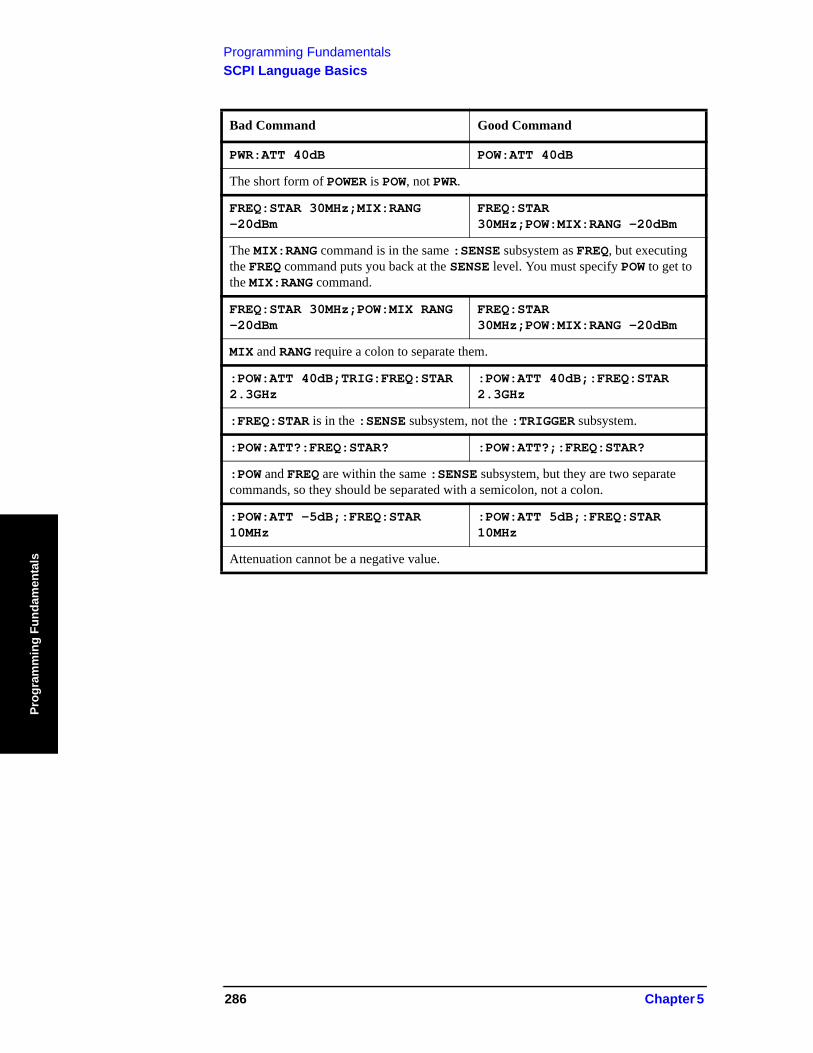
Programming FundamentalsSCPI Language Basics
Prog
ram
min
g Fu
ndam
enta
ls
Bad Command Good Command
PWR:ATT 40dB POW:ATT 40dB
The short form of POWER is POW, not PWR.
FREQ:STAR 30MHz;MIX:RANG -20dBm
FREQ:STAR 30MHz;POW:MIX:RANG -20dBm
The MIX:RANG command is in the same :SENSE subsystem as FREQ, but executing the FREQ command puts you back at the SENSE level. You must specify POW to get to the MIX:RANG command.
FREQ:STAR 30MHz;POW:MIX RANG -20dBm
FREQ:STAR 30MHz;POW:MIX:RANG -20dBm
MIX and RANG require a colon to separate them.
:POW:ATT 40dB;TRIG:FREQ:STAR 2.3GHz
:POW:ATT 40dB;:FREQ:STAR 2.3GHz
:FREQ:STAR is in the :SENSE subsystem, not the :TRIGGER subsystem.
:POW:ATT?:FREQ:STAR? :POW:ATT?;:FREQ:STAR?
:POW and FREQ are within the same :SENSE subsystem, but they are two separate commands, so they should be separated with a semicolon, not a colon.
:POW:ATT -5dB;:FREQ:STAR 10MHz
:POW:ATT 5dB;:FREQ:STAR 10MHz
Attenuation cannot be a negative value.
286 Chapter 5
Programming FundamentalsImproving Measurement Speed
Programm
ing Fundamentals
Improving Measurement SpeedThere are a number of things you can do in your programs to make them run faster:
“Turn off the display updates” on page 287
“Use binary data format instead of ASCII” on page 287
“Minimize the number of GPIB transactions for PSA” on page 288
“Put ADC Ranging in Bypass for FFT Measurements for PSA” on page 288
“Minimize DUT/instrument setup changes” on page 289
“Consider using USB (Option 111) or LAN instead of GPIB” on page 289
There are additional things you can do to run faster if you are using a measurement personality option (i.e. instrument Modes other than the standard Spectrum Analysis Mode). These considerations only apply to specific option modes.
“Using an Option Mode: Minimize the number of GPIB transactions” on page 289
“Using an Option Mode: Avoid automatic attenuator setting” on page 290
“Using an Option Mode: Optimize your GSM output RF spectrum switching measurement” on page 290
“Using an Option Mode: Avoid using RFBurst trigger for single burst signals” on page 290
“Using an Option Mode: When making power measurements on multiple bursts or slots, use CALCulate:DATA<n>:COMPress?” on page 291
Turn off the display updates
:DISPlay:ENABle OFF turns off the display. That is, the data may still be visible, but it will no longer be updated. Updating the display slows down the measurement. For remote testing, since the computer is processing the data rather than a person, there is no need to display the data on the analyzer screen.
Use binary data format instead of ASCII
The ASCII data format is the instrument default since it is easier for people to understand and is required by SCPI for *RST. However, data input/output is faster using the binary formats.
:FORMat:DATA REAL,64 selects the 64-bit binary data format for all your numerical data queries. You may need to swap the byte order if you are using a PC rather than UNIX. NORMal is the default byte order. Use :FORMat:BORDer SWAP to change the byte order so that the least significant byte is sent first. (Real,32 which is smaller and somewhat faster, should only be used if you don’t need full resolution for your data. Some frequency data may require full 64 bit
Chapter 5 287

Programming FundamentalsImproving Measurement Speed
Prog
ram
min
g Fu
ndam
enta
ls
resolution.)
When using the binary format, data is sent in a block of bytes with an ASCII header. A data query would return the block of data in the following format: #DNNN<nnn binary data bytes>
To parse the data:
• Read two characters (#D), where D tells you how many N characters follow the D character.
• Read D characters, the resulting integer specifies the number of data bytes sent.• Read the bytes into a real array.
For example, suppose the header is #512320.
• The first character/digit in the header (5) tells you how many additional digits there are in the header.
• The 12320 means 12 thousand, 3 hundred, 20 data bytes follow the header.• Divide this number of bytes by your current data format (bytes/data point), 8
for real,64. For this example, there are 1540 data points in the block of data.
Minimize the number of GPIB transactions for PSA
When you are using the GPIB for control of your instrument, each transaction requires driver overhead and bus handshaking, so minimizing these transactions reduces the time used.
You can reduce bus transactions by sending multiple commands per transaction. See the information on “Putting Multiple Commands on the Same Line” in the SCPI Language Basics section.
If you are using the MEASURE key measurements and are making the same measurement multiple times with small changes in the measurement setup, use the single READ command. It is faster then using INITiate and FETCh.
Avoid unnecessary use of *RST
Remember that while *RST does not change the current Mode, it presets all the measurements and settings to their factory defaults. This forces you to reset your analyzer’s measurement settings even if they use similar mode setup or measurement settings. See Minimize DUT/instrument setup changes below. (Also note that *RST may put the instrument in single measurement/sweep for some modes.)
Put ADC Ranging in Bypass for FFT Measurements for PSA
Setting ADC ranging to the Bypass mode can speed FFT measurements up by 10% to 50%. (Use ADC:RANG NONE) Bypass allows triggered FFT measurements to occur at the trigger time instead of following an autoranging time, so it can improve measurement speed. It does, however, add additional noise degrading your signal to noise level, so it should be used carefully.
288 Chapter 5
Programming FundamentalsImproving Measurement Speed
Programm
ing Fundamentals
Minimize DUT/instrument setup changes
• Some instrument setup parameters are common to multiple measurements. You should look at your measurement process with an eye toward minimizing setup changes. If your test process involves nested loops, make sure that the inner-most loop is the fastest. Also, check if the loops could be nested in a different order to reduce the number of parameter changes as you step through the test.
• Are you are using the measurements under the PSA MEASURE key? Remember that if you have already set your Meas Setup parameters for a measurement, and you want to make another one of these measurements later, use READ:<meas>?. The MEASure:<meas>?. command resets all the settings to the defaults, while READ changes back to that measurement without changing the setup parameters from the previous use.
• Are you are using the Measurements under the MEASURE key? Remember that Mode Setup parameters remain constant across all the measurements in that mode (e.g. center/channel frequency, amplitude, radio standard, input selection, trigger setup). You don’t have to re-initialize them each time you change to a different measurement.
Consider using USB (Option 111) or LAN instead of GPIB
USB and LAN allow faster I/O of data, especially if you are moving large blocks of data. You will not get this improved throughput using LAN if there is excessive LAN traffic (i.e. your test instrument is connected to enterprise LAN). You may want to use a private LAN that is only for your test system.
Using an Option Mode: Minimize the number of GPIB transactions
When you are using the GPIB for control of your instrument, each transaction requires driver overhead and bus handshaking, so minimizing these transactions reduces the time used.
• You can reduce bus transactions by sending multiple commands per transaction. See the information on “Putting Multiple Commands on the Same Line” in the SCPI Language Basics section.
• If you are making the same measurement multiple times with small changes in the measurement setup, use the READ command. It is faster then using INITiate and FETCh.
• If you are changing the frequency and making a measurement repeatedly, you can reduce transactions by sending the optional frequency parameter with your READ command. (for example, READ:<meas>? {<freq>}) These optional parameters are not available in some personality modes on the PSA, such as Spectrum Analysis or Phase Noise.The CONFigure/MEASure/READ commands for measurements in the option Modes allow you to send center frequency setup information along with the command. (for example, MEAS:PVT? 935.2MHz) This sets the power vs. time
Chapter 5 289
Programming FundamentalsImproving Measurement Speed
Prog
ram
min
g Fu
ndam
enta
ls
measurement to it’s defaults, then changes the center frequency to 935.2 MHz, initiates a measurement, waits until it is complete and returns the measurement data.
• If you are doing bottom/middle/top measurements on base stations, you can reduce transactions by making a time slot active at each of the B,M,T frequencies. Then issue three measurements at once in the programming code and retrieve three data sets with just one GPIB transaction pair (write, read).For example, send READ:PFER? <Freq_bottom>;PFER? <Freq_middle>;PFER? <Freq_top> This single transaction initiates three different phase and frequency error measurements at each of the three different frequencies provided and returns the data. Then you read the three sets of data.
Using an Option Mode: Avoid automatic attenuator setting
The internal process for automatically setting the value of the attenuator requires measuring an initial burst to identify the proper attenuator setting before the next burst can be measured properly. If you know the amount of attenuation or the signal level needed for your measurement, just set it.
Note that spurious types of measurements must be done with the attenuator set to automatic (for measurements like: output RF spectrum, transmit spurs, adjacent channel power, spectrum emission mask). These types of measurements start by tuning to the signal, then they tune away from it and must be able to reset the attenuation value as needed.
Using an Option Mode: Optimize your GSM output RF spectrum switching measurement
For ORFS (switching), setting the break frequency to zero (0) puts the analyzer in a measurement setup where it can use a direct time measurement algorithm, instead of an FFT-based algorithm. This non-FFT approach is faster. (However, remember that your break frequency for ORFS (modulation) measurements must be >400 kHz for valid measurements, so you will need to change the break frequency if you are making both types of measurements.)
Using an Option Mode: Avoid using RFBurst trigger for single burst signals
RFBurst triggering works best when measuring signals with repetitive bursts. For a non-repetitive or single burst signals, use the IF (video) trigger or external trigger, depending on what you have available.
RFBurst triggering depends on its establishment of a valid triggering reference level, based on previous bursts. If you only have a single burst, the peak detection nature of this triggering function, may result in the trigger being done at the wrong level/point generating incorrect data, or it may not trigger at all.
Are you making a single burst measurement?
To get consistent triggering and good data for this type of measurement
290 Chapter 5
Programming FundamentalsImproving Measurement Speed
Programm
ing Fundamentals
application, you need to synchronize the triggering of the DUT with the analyzer. You should use the analyzer’s internal status system for this.
The first step in this process is to initialize the status register mask to look for the “waiting for trigger” condition (bit 5). Use :STATus:OPERation:ENABle 32
Then, in the measurement loop:
1. :STATus:OPERation:EVENt? This query of the operation event register is to clear the current register contents.
2. :READ:PVT? initiates a measurement (in this example, for GSM power versus time) using the previous setup. The measurement will then be waiting for the trigger.Make sure the attenuation is set manually. Do NOT use automatic attenuation as this requires an additional burst to determine the proper attenuation level before the measurement can be made.
3. Create a small loop that will serial poll the instrument for a status byte value of binary 128. Then wait 1 msec (100 ms if the display is left on/enabled) before checking again, to keep the bus traffic down. These two commands are repeated until the condition is set, so we know that the trigger is armed and ready.
4. Trigger your DUT to send the burst.5. Return the measurement data to your computer.
NOTE This process cannot be done by using with the current VXI plug-n-play driver implementation. You will need to use the above SCPI commands.
Using an Option Mode: When making power measurements on multiple bursts or slots, use CALCulate:DATA<n>:COMPress?
The CALC:DATA:COMP? query is the fastest way to measure power data for multiple bursts/slots. There are two reasons for this: 1. it can be used to measure data across multiple, consecutive slots/frames with just one measurement, instead of a separate measurement on each slot, and 2. it can pre-process and/or decimate the data so that you only return the information that you need which minimizes data transfer to the computer.
For example: let’s say you want to do a power measurement for a GSM base station where you generate a repeating frame with 8 different power levels. You can gather all the data with a single CALC:DATA:COMP? acquisition, using the waveform measurement.
With CALC:DATA2:COMP? MEAN,9,197,1730 you can measure the mean power in those bursts. This single command will measure the data across all 8 frames, locate the first slot/burst in each of the frames, calculate the mean power of those bursts, then return the resulting 8 values.
NOTE For later version of firmware (after PSA A.02.00) you can use equivalent time values for the CALC:DATA<n>:COMP? query. The command would then be
Chapter 5 291
Programming FundamentalsImproving Measurement Speed
Prog
ram
min
g Fu
ndam
enta
ls
CALC:DATA2:COMP? MEAN,25us,526us,579.6us,8
Let’s set up the GSM Waveform measurement:
• :CONF:WAV? turns on the waveform measurement• :WAV:BAND 300khz sets a resolution bandwidth of 300 kHz• :WAV:SWE:TIME 5ms sets a sweep time of 5 milliseconds• :WAV:BAND:TYPE FLAT selects the flat filter type• :WAV:DEC 4;DEC:STAT ON selects a decimation of 4 and turns on
decimation. This reduces the amount of data that needs to be sent since the instrument hardware decimates (throws some away).
• :INIT to initiate a measurement and acquire the data• CALC:DATA2:COMP? MEAN,25us,526us,579.6us,8 to return the desired
data
There are two versions of this command depending on your firmware revision. Earlier revisions require the optional variables be entered in terms of their position in the trace data array. Current instruments allow the variables to be entered in terms of time.
For early firmware revisions you need to know the sample interval. In the waveform measurement it is equal to the aperture value. Query :WAVeform:APERture? to find the sample interval. (Note: the WAV:APER? command always takes decimation into account.) The sample interval (aperture value) is dependent on the settings for resolution bandwidth, filter type, and decimation. See the following table to see how these value relate.
The parameters for this GSM example are: MEAN,9,197,1730 (or with later firmware: MEAN,25us,526us,579.6us,8)
• MEAN calculates the mean of the measurement points indicated• 9 is how many points you want to discard before you look at the data. This
allows you to skip over any “unsettled” values at the beginning of the burst. You can calculate this start offset by (25μs/sampleInterval)l
• 197 is the length of the data you want to use. This would be the portion of the burst that you want to find the mean power over. You can calculate this length by (526μs/sampleInterval)
• 1730 is how much data you have before you repeat the process. For this example it’s the time between the start offset point on the burst in the first slot (first frame) to the same spot on the burst in the first slot (second frame). You can calculate this by (576.9μs*N/sampleInterval) where N is the number of data items that you want. In this case it is the number of slots in the frame, N=8.)
Table 5-1 GSM Parameters for 1 Slot/Frame Measurement Requirements
Resolution Bandwidth
Filter Type Decimation Aperture Start Length Repeat
500 or 300 kHz Flat or Gaussian
4 or 1 dependent on settings
24 μseca 526 μseca 576.9 μseca
500 kHz Gaussian 1 0.2 μsec 124 2630 2884.6
292 Chapter 5
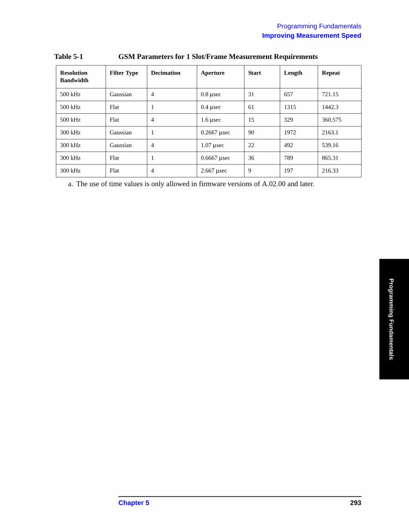
Programming FundamentalsImproving Measurement Speed
Programm
ing Fundamentals
500 kHz Gaussian 4 0.8 μsec 31 657 721.15
500 kHz Flat 1 0.4 μsec 61 1315 1442.3
500 kHz Flat 4 1.6 μsec 15 329 360.575
300 kHz Gaussian 1 0.2667 μsec 90 1972 2163.1
300 kHz Gaussian 4 1.07 μsec 22 492 539.16
300 kHz Flat 1 0.6667 μsec 36 789 865.31
300 kHz Flat 4 2.667 μsec 9 197 216.33
a. The use of time values is only allowed in firmware versions of A.02.00 and later.
Table 5-1 GSM Parameters for 1 Slot/Frame Measurement Requirements
Resolution Bandwidth
Filter Type Decimation Aperture Start Length Repeat
Chapter 5 293
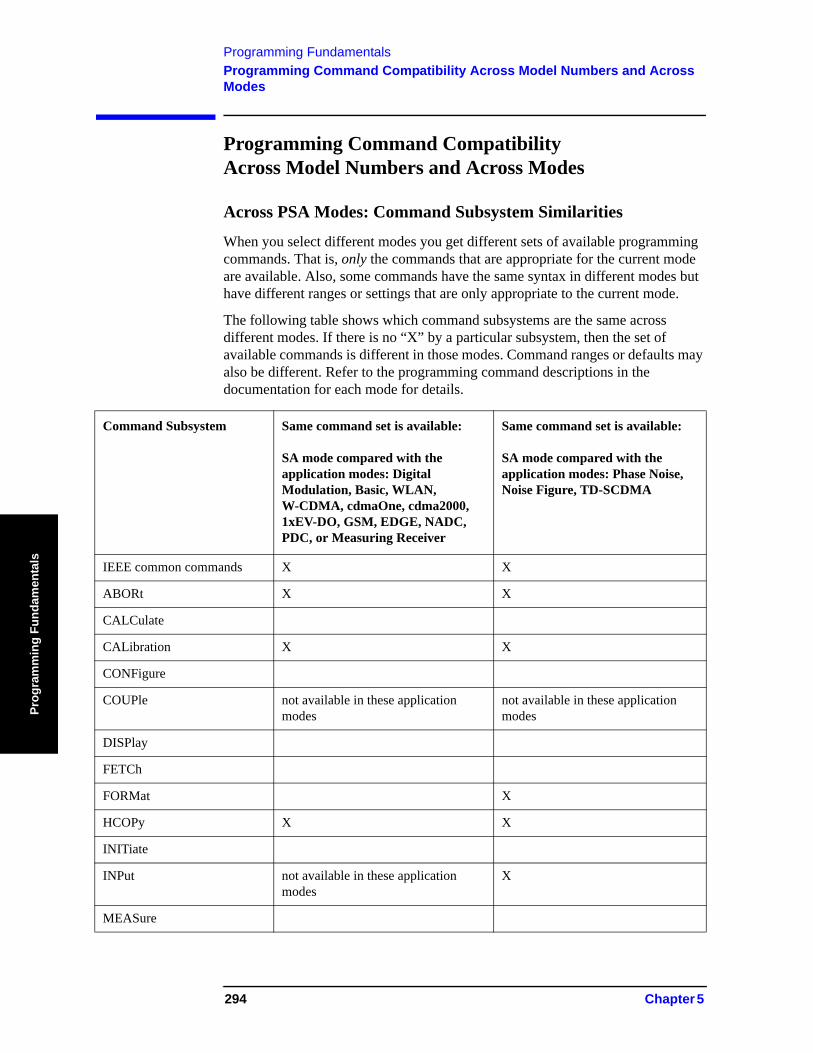
Programming FundamentalsProgramming Command Compatibility Across Model Numbers and Across Modes
Prog
ram
min
g Fu
ndam
enta
ls
Programming Command Compatibility Across Model Numbers and Across Modes
Across PSA Modes: Command Subsystem Similarities
When you select different modes you get different sets of available programming commands. That is, only the commands that are appropriate for the current mode are available. Also, some commands have the same syntax in different modes but have different ranges or settings that are only appropriate to the current mode.
The following table shows which command subsystems are the same across different modes. If there is no “X” by a particular subsystem, then the set of available commands is different in those modes. Command ranges or defaults may also be different. Refer to the programming command descriptions in the documentation for each mode for details.
Command Subsystem Same command set is available:
SA mode compared with the application modes: Digital Modulation, Basic, WLAN, W-CDMA, cdmaOne, cdma2000, 1xEV-DO, GSM, EDGE, NADC, PDC, or Measuring Receiver
Same command set is available:
SA mode compared with the application modes: Phase Noise, Noise Figure, TD-SCDMA
IEEE common commands X X
ABORt X X
CALCulate
CALibration X X
CONFigure
COUPle not available in these application modes
not available in these application modes
DISPlay
FETCh
FORMat X
HCOPy X X
INITiate
INPut not available in these application modes
X
MEASure
294 Chapter 5
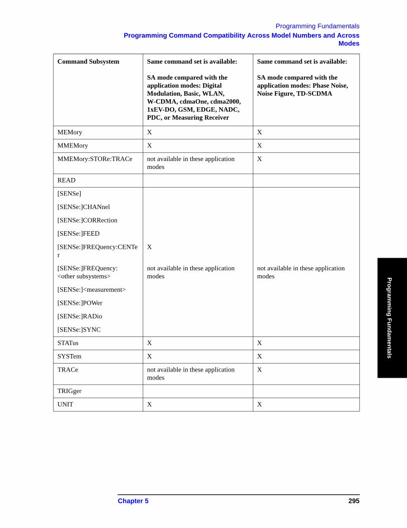
Programming FundamentalsProgramming Command Compatibility Across Model Numbers and Across
Modes
Programm
ing Fundamentals
MEMory X X
MMEMory X X
MMEMory:STORe:TRACe not available in these application modes
X
READ
[SENSe]
[SENSe:]CHANnel
[SENSe:]CORRection
[SENSe:]FEED
[SENSe:]FREQuency:CENTer
X
[SENSe:]FREQuency: <other subsystems>
not available in these application modes
not available in these application modes
[SENSe:]<measurement>
[SENSe:]POWer
[SENSe:]RADio
[SENSe:]SYNC
STATus X X
SYSTem X X
TRACe not available in these application modes
X
TRIGger
UNIT X X
Command Subsystem Same command set is available:
SA mode compared with the application modes: Digital Modulation, Basic, WLAN, W-CDMA, cdmaOne, cdma2000, 1xEV-DO, GSM, EDGE, NADC, PDC, or Measuring Receiver
Same command set is available:
SA mode compared with the application modes: Phase Noise, Noise Figure, TD-SCDMA
Chapter 5 295
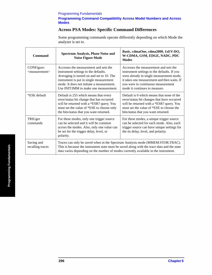
Programming FundamentalsProgramming Command Compatibility Across Model Numbers and Across Modes
Prog
ram
min
g Fu
ndam
enta
ls
Across PSA Modes: Specific Command Differences
Some programming commands operate differently depending on which Mode the analyzer is set to.
Command Spectrum Analysis, Phase Noise and Noise Figure Mode
Basic, cdmaOne, cdma2000, 1xEV-DO, W-CDMA, GSM, EDGE, NADC, PDC Modes
CONFigure: <measurement>
Accesses the measurement and sets the instrument settings to the defaults. Averaging is turned on and set to 10. The instrument is put in single measurement mode. It does not initiate a measurement. Use INIT:IMM to make one measurement.
Accesses the measurement and sets the instrument settings to the defaults. If you were already in single measurement mode, it takes one measurement and then waits. If you were in continuous measurement mode it continues to measure.
*ESE default Default is 255 which means that every error/status bit change that has occurred will be returned with a *ESR? query. You must set the value of *ESE to choose only the bits/status that you want returned.
Default is 0 which means that none of the error/status bit changes that have occurred will be returned with a *ESR? query. You must set the value of *ESE to choose the bits/status that you want returned.
TRIGger commands
For these modes, only one trigger source can be selected and it will be common across the modes. Also, only one value can be set for the trigger delay, level, or polarity.
For these modes, a unique trigger source can be selected for each mode. Also, each trigger source can have unique settings for the its delay, level, and polarity.
Saving and recalling traces
Traces can only be saved when in the Spectrum Analysis mode (MMEM:STOR:TRAC). This is because the instrument state must be saved along with the trace data and the state data varies depending on the number of modes currently available in the instrument.
296 Chapter 5
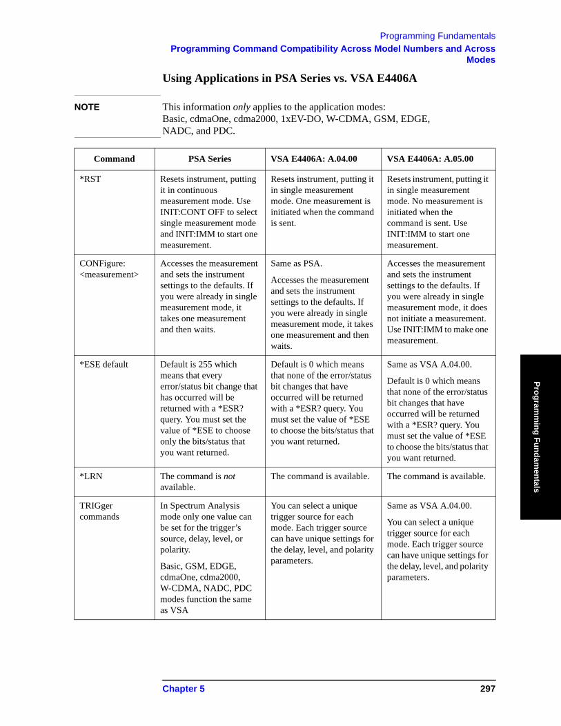
Programming FundamentalsProgramming Command Compatibility Across Model Numbers and Across
Modes
Programm
ing Fundamentals
Using Applications in PSA Series vs. VSA E4406A
NOTE This information only applies to the application modes: Basic, cdmaOne, cdma2000, 1xEV-DO, W-CDMA, GSM, EDGE, NADC, and PDC.
Command PSA Series VSA E4406A: A.04.00 VSA E4406A: A.05.00
*RST Resets instrument, putting it in continuous measurement mode. Use INIT:CONT OFF to select single measurement mode and INIT:IMM to start one measurement.
Resets instrument, putting it in single measurement mode. One measurement is initiated when the command is sent.
Resets instrument, putting it in single measurement mode. No measurement is initiated when the command is sent. Use INIT:IMM to start one measurement.
CONFigure: <measurement>
Accesses the measurement and sets the instrument settings to the defaults. If you were already in single measurement mode, it takes one measurement and then waits.
Same as PSA.
Accesses the measurement and sets the instrument settings to the defaults. If you were already in single measurement mode, it takes one measurement and then waits.
Accesses the measurement and sets the instrument settings to the defaults. If you were already in single measurement mode, it does not initiate a measurement. Use INIT:IMM to make one measurement.
*ESE default Default is 255 which means that every error/status bit change that has occurred will be returned with a *ESR? query. You must set the value of *ESE to choose only the bits/status that you want returned.
Default is 0 which means that none of the error/status bit changes that have occurred will be returned with a *ESR? query. You must set the value of *ESE to choose the bits/status that you want returned.
Same as VSA A.04.00.
Default is 0 which means that none of the error/status bit changes that have occurred will be returned with a *ESR? query. You must set the value of *ESE to choose the bits/status that you want returned.
*LRN The command is not available.
The command is available. The command is available.
TRIGger commands
In Spectrum Analysis mode only one value can be set for the trigger’s source, delay, level, or polarity.
Basic, GSM, EDGE, cdmaOne, cdma2000, W-CDMA, NADC, PDC modes function the same as VSA
You can select a unique trigger source for each mode. Each trigger source can have unique settings for the delay, level, and polarity parameters.
Same as VSA A.04.00.
You can select a unique trigger source for each mode. Each trigger source can have unique settings for the delay, level, and polarity parameters.
Chapter 5 297
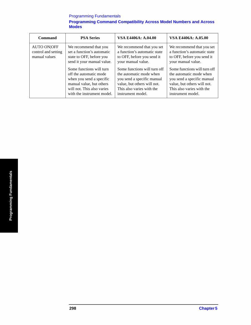
Programming FundamentalsProgramming Command Compatibility Across Model Numbers and Across Modes
Prog
ram
min
g Fu
ndam
enta
ls
AUTO ON|OFF control and setting manual values
We recommend that you set a function’s automatic state to OFF, before you send it your manual value.
Some functions will turn off the automatic mode when you send a specific manual value, but others will not. This also varies with the instrument model.
We recommend that you set a function’s automatic state to OFF, before you send it your manual value.
Some functions will turn off the automatic mode when you send a specific manual value, but others will not. This also varies with the instrument model.
We recommend that you set a function’s automatic state to OFF, before you send it your manual value.
Some functions will turn off the automatic mode when you send a specific manual value, but others will not. This also varies with the instrument model.
Command PSA Series VSA E4406A: A.04.00 VSA E4406A: A.05.00
298 Chapter 5
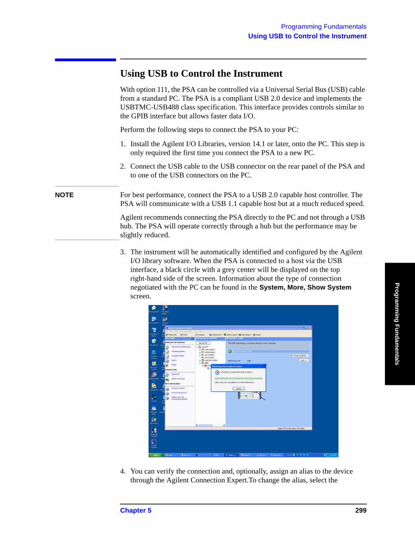
Programming FundamentalsUsing USB to Control the Instrument
Programm
ing Fundamentals
Using USB to Control the InstrumentWith option 111, the PSA can be controlled via a Universal Serial Bus (USB) cable from a standard PC. The PSA is a compliant USB 2.0 device and implements the USBTMC-USB488 class specification. This interface provides controls similar to the GPIB interface but allows faster data I/O.
Perform the following steps to connect the PSA to your PC:
1. Install the Agilent I/O Libraries, version 14.1 or later, onto the PC. This step is only required the first time you connect the PSA to a new PC.
2. Connect the USB cable to the USB connector on the rear panel of the PSA and to one of the USB connectors on the PC.
NOTE For best performance, connect the PSA to a USB 2.0 capable host controller. The PSA will communicate with a USB 1.1 capable host but at a much reduced speed.
Agilent recommends connecting the PSA directly to the PC and not through a USB hub. The PSA will operate correctly through a hub but the performance may be slightly reduced.
3. The instrument will be automatically identified and configured by the Agilent I/O library software. When the PSA is connected to a host via the USB interface, a black circle with a grey center will be displayed on the top right-hand side of the screen. Information about the type of connection negotiated with the PC can be found in the System, More, Show System screen.
4. You can verify the connection and, optionally, assign an alias to the device through the Agilent Connection Expert.To change the alias, select the
Chapter 5 299
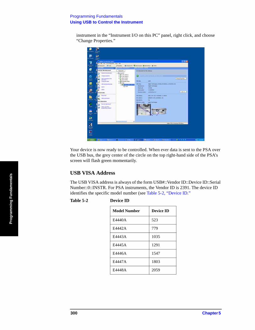
Programming FundamentalsUsing USB to Control the Instrument
Prog
ram
min
g Fu
ndam
enta
ls
instrument in the “Instrument I/O on this PC” panel, right click, and choose “Change Properties.”
Your device is now ready to be controlled. When ever data is sent to the PSA over the USB bus, the grey center of the circle on the top right-hand side of the PSA’s screen will flash green momentarily.
USB VISA Address
The USB VISA address is always of the form USB#::Vendor ID::Device ID::Serial Number::0::INSTR. For PSA instruments, the Vendor ID is 2391. The device ID identifies the specific model number (see Table 5-2, “Device ID.”Table 5-2 Device ID
Model Number Device ID
E4440A 523
E4442A 779
E4443A 1035
E4445A 1291
E4446A 1547
E4447A 1803
E4448A 2059
300 Chapter 5
Programming FundamentalsUsing USB to Control the Instrument
Programm
ing Fundamentals
Optimizing USB Performance
To achieve the maximum throughput on the USB interface, Agilent recommends the following:
1. Use a “high-speed” connection. When connected to a USB 2.0 host, the PSA will negotiate a “high-speed” (480 Mbps) connection with the PC. If you connect the PSA to a USB 1.1 host or to a USB 1.1 hub, the PSA will negotiate a “full-speed” (12 Mbps) connection only. The type of connection currently negotiated will be shown on the System, More, Show System screen of the PSA.
2. Request large transfers.The USB interface performs best when transferring large amounts of data in a single burst. Breaking up a transfer into smaller chunks will introduce idle times on the USB bus when the instrument is preparing to send the next chunk. With a single large transfer, these delays are not present and the bus utilization is much higher.
Example 5-1 Large Transfer:
char *buffer;buffer = malloc(102400);viRead(vi,buffer,102400,&cnt);
Example 5-2 Broken-up Transfer:
char buffer[1024];int I;for(i=0; i < 100; i++){ viRead(vi,buffer,1024,&cnt);}
3. Choose the best format.The SCPI commands :FORMat[:TRACe][:DATa] and :FORMat:BORDer can be used to set the format of the returned trace data. These commands are often used to reduce the amount of data the PSA will send, which usually results in faster trace transfers. However, with the USB interface, it can be faster for the PSA to transfer the complete trace rather than convert the trace format and send the smaller amount of data. In most cases, the best throughput is achieved by sending the trace data in real 64-bit floating point format in NORMAL byte order, and then converting the trace to the correct form in the PC. The setting for this would be:
FORM REAL,64 FORM:BORD NORM
4. Do not enable termination character.The Visa Attribute VI_ATTR_TERMCHAR_EN can be set to cause the viRead()function to stop reading when the specified character is received. This feature causes a significant throughput reduction.
Chapter 5 301
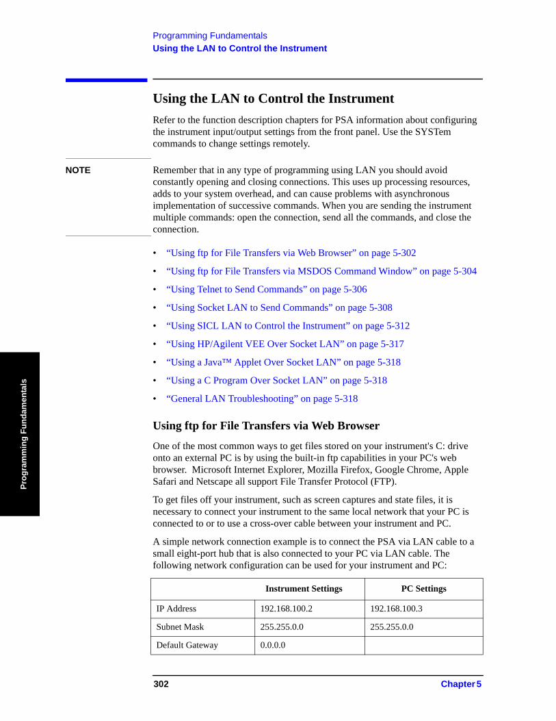
Programming FundamentalsUsing the LAN to Control the Instrument
Prog
ram
min
g Fu
ndam
enta
ls
Using the LAN to Control the InstrumentRefer to the function description chapters for PSA information about configuring the instrument input/output settings from the front panel. Use the SYSTem commands to change settings remotely.
NOTE Remember that in any type of programming using LAN you should avoid constantly opening and closing connections. This uses up processing resources, adds to your system overhead, and can cause problems with asynchronous implementation of successive commands. When you are sending the instrument multiple commands: open the connection, send all the commands, and close the connection.
• “Using ftp for File Transfers via Web Browser” on page 5-302
• “Using ftp for File Transfers via MSDOS Command Window” on page 5-304
• “Using Telnet to Send Commands” on page 5-306
• “Using Socket LAN to Send Commands” on page 5-308
• “Using SICL LAN to Control the Instrument” on page 5-312
• “Using HP/Agilent VEE Over Socket LAN” on page 5-317
• “Using a Java™ Applet Over Socket LAN” on page 5-318
• “Using a C Program Over Socket LAN” on page 5-318
• “General LAN Troubleshooting” on page 5-318
Using ftp for File Transfers via Web Browser
One of the most common ways to get files stored on your instrument's C: drive onto an external PC is by using the built-in ftp capabilities in your PC's web browser. Microsoft Internet Explorer, Mozilla Firefox, Google Chrome, Apple Safari and Netscape all support File Transfer Protocol (FTP).
To get files off your instrument, such as screen captures and state files, it is necessary to connect your instrument to the same local network that your PC is connected to or to use a cross-over cable between your instrument and PC.
A simple network connection example is to connect the PSA via LAN cable to a small eight-port hub that is also connected to your PC via LAN cable. The following network configuration can be used for your instrument and PC:
Instrument Settings PC Settings
IP Address 192.168.100.2 192.168.100.3
Subnet Mask 255.255.0.0 255.255.0.0
Default Gateway 0.0.0.0
302 Chapter 5
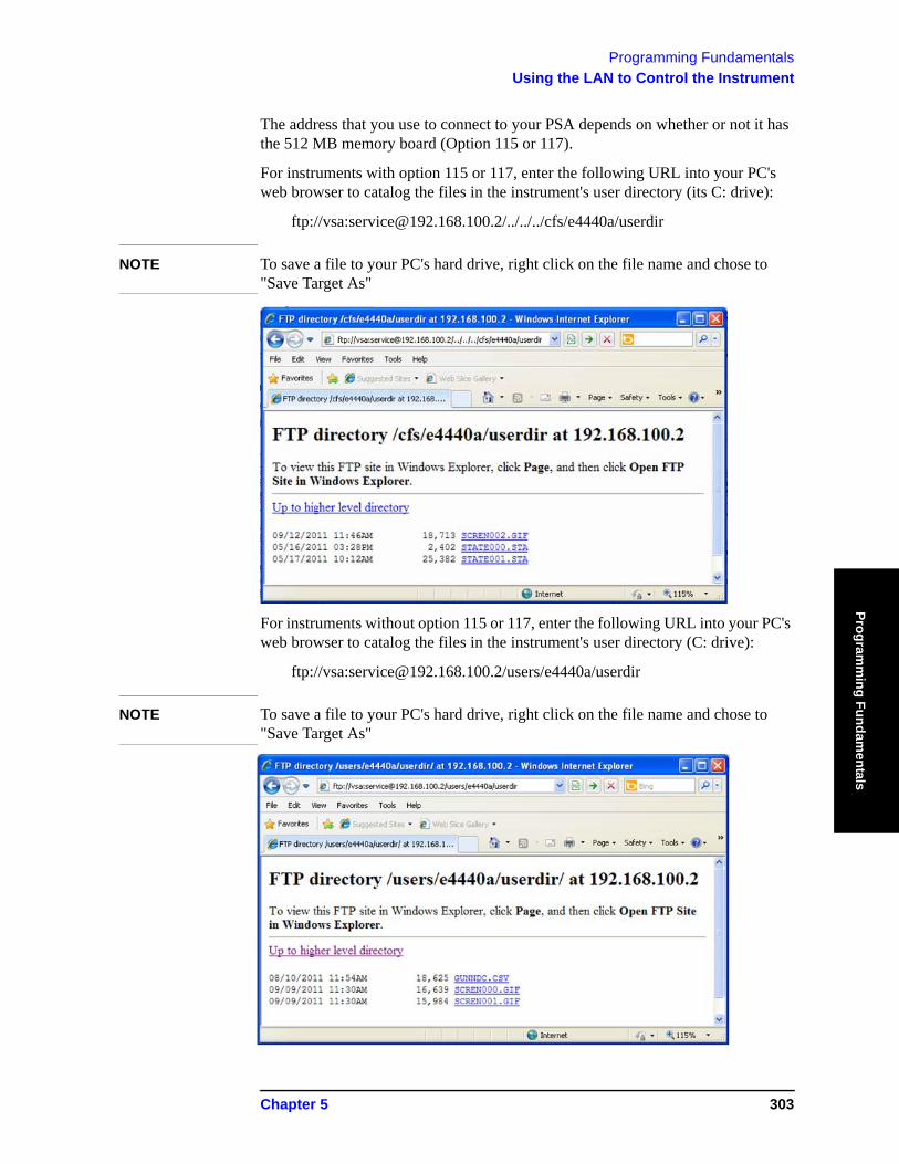
Programming FundamentalsUsing the LAN to Control the Instrument
Programm
ing Fundamentals
The address that you use to connect to your PSA depends on whether or not it has the 512 MB memory board (Option 115 or 117).
For instruments with option 115 or 117, enter the following URL into your PC's web browser to catalog the files in the instrument's user directory (its C: drive):
ftp://vsa:[email protected]/../../../cfs/e4440a/userdir
NOTE To save a file to your PC's hard drive, right click on the file name and chose to "Save Target As"
For instruments without option 115 or 117, enter the following URL into your PC's web browser to catalog the files in the instrument's user directory (C: drive):
ftp://vsa:[email protected]/users/e4440a/userdir
NOTE To save a file to your PC's hard drive, right click on the file name and chose to "Save Target As"
Chapter 5 303
Programming FundamentalsUsing the LAN to Control the Instrument
Prog
ram
min
g Fu
ndam
enta
ls
Using ftp for File Transfers via MSDOS Command Window
You can use the instrument LAN connection to transfer files. For example, you can use the ftp functionality to download instrument screen dumps to an external server.
The following is an example of an ftp session from an MSDOS window on a PC:
1. ftp 192.168.100.2 (enter the instrument IP address, found/set from the front panel by pressing System, Config I/O)
2. At the user name prompt, enter: vsa3. At the password prompt, enter: service
For instruments without Option 115 or 117:To change directory to the user directory type the following command at the ftp prompt: cd ../../../cfs/e4440a/userdirYou are now in the instrument’s user directory which is also the root "C:" directory accessible via the instruments' firmware. You can get files from the instrument. The ftp commands in the following steps may not all be available from your controller.
For intruments with Option 115 or 117:You must enter the following command to get to the active user directory:cd users/e4440a/userdirTo show the ftp commands available on your system, type help at the prompt. To end the ftp session, type quit
4. ls (list all available files, ls -la shows file permissions)5. bin (change to the binary file transfer mode)6. get myfilename (enter the file name; the name is case sensitive)
This “gets” (copies) your file. The file is copied to the location you were pointing to when you started the ftp process. To query the current location, enter lcd . (include the period). To change the current location, enter the desired path/directory location as follows: lcd C:\my path\mydir
The Standard UNIX FTP Command:
Synopsis ftp [-g] [-i] [-n] [-v] [server-host] [-B DataSocketBufferSize]
Description The ftp command is used to transfer files using the File Transfer Protocol. ftp transfers files over a network connection between a local machine and the remote server-host.
Options and Parameters When ftp is invoked with a server-host specified, a connection is opened immediately. Otherwise, ftp waits for user commands.
304 Chapter 5
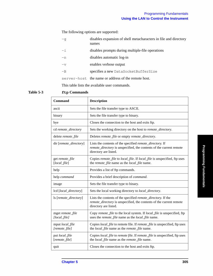
Programming FundamentalsUsing the LAN to Control the Instrument
Programm
ing Fundamentals
The following options are supported:
-g disables expansion of shell metacharacters in file and directory names
-i disables prompts during multiple-file operations
-n disables automatic log-in
-v enables verbose output
-B specifies a new DataSocketBufferSize
server-host the name or address of the remote host.
This table lists the available user commands.
Table 5-3 ftp Commands
Command Description
ascii Sets the file transfer type to ASCII.
binary Sets the file transfer type to binary.
bye Closes the connection to the host and exits ftp.
cd remote_directory Sets the working directory on the host to remote_directory.
delete remote_file Deletes remote_file or empty remote_directory.
dir [remote_directory] Lists the contents of the specified remote_directory. If remote_directory is unspecified, the contents of the current remote directory are listed.
get remote_file [local_file]
Copies remote_file to local_file. If local_file is unspecified, ftp uses the remote_file name as the local_file name.
help Provides a list of ftp commands.
help command Provides a brief description of command.
image Sets the file transfer type to binary.
lcd [local_directory] Sets the local working directory to local_directory.
ls [remote_directory] Lists the contents of the specified remote_directory. If the remote_directory is unspecified, the contents of the current remote directory are listed.
mget remote_file [local_file]
Copy remote_file to the local system. If local_file is unspecified, ftp uses the remote_file name as the local_file name.
mput local_file [remote_file]
Copies local_file to remote file. If remote_file is unspecified, ftp uses the local_file name as the remote_file name.
put local_file [remote_file]
Copies local_file to remote file. If remote_file is unspecified, ftp uses the local_file name as the remote_file name.
quit Closes the connection to the host and exits ftp.
Chapter 5 305
Programming FundamentalsUsing the LAN to Control the Instrument
Prog
ram
min
g Fu
ndam
enta
ls
Using Telnet to Send Commands
Using telnet to send commands to your instrument works in a similar way to communicating over GPIB. You establish a connection with the instrument, and then send or receive information using SCPI commands.
NOTE If you need to control the bus using “device clear” or SRQ’s, you can use SICL LAN. SICL LAN provides control of your instrument via IEEE 488.2 GPIB over the LAN. See “Using SICL LAN to Control the Instrument” on page 5-312. in this chapter.
NOTE STATus bits that are already set when the socket connection is made cannot be read. Only status bit changes that occur after the socket connection is made will returned when the status register is queried.
On unix or PC:
The syntax of the telnet command is:
telnet <IP address> <5023>
The initial telnet connection message will be displayed and then a SCPI> prompt. At the SCPI prompt, simply enter the desired SCPI commands.
On a PC (with telnet gui that has host/port setting menu):
You would type at the dos prompt
telnet
NOTE Early versions of Windows XP Telnet will initially only send a LF, not a CRLF. So the telnet port 5023 does not work. You can manually correct this situation by sending the escape sequence and then a CRLF. After connecting to the instrument, type in the telnet window:
• Crtl-] (press the control and ] keys simultaneously)• set crlf <enter key>• <enter key>
You should now see the SCPI> prompt and you can continue working.
The Windows XP Service Pack 2 fixes this problem. You can get Service Pack 2 from the Microsoft Windows update website.
Unix Telnet Example:
To connect to the instrument with host name aaa and port number 5023, enter the following command:
telnet aaa 5023
When you connect to the instrument, it will display a welcome message and a command prompt. The instrument is now ready to accept your SCPI commands.
306 Chapter 5

Programming FundamentalsUsing the LAN to Control the Instrument
Programm
ing Fundamentals
As you type SCPI commands, query results appear on the next line. At any time, you can send a <device clear> by pressing cntrl-c on your keyboard. When you are done, break the telnet connection using your escape character, and type quit.
When the instrument responds with the welcome message and the SCPI prompt, you can immediately enter programming (SCPI) commands.
Typical PSA commands might be:
CALC:MARK:MODE POS CALC:MARK:MAX CALC:MARK:X?
The small program above sets the instrument to measure a signal amplitude by placing a marker on the maximum point of the trace, and then querying the instrument for the amplitude of the marker.
You need to press Enter after typing in each command. After pressing Enter on the last line in the example above, the instrument returns the amplitude level of the marker to your computer and displays it on the next line. For example, after typing (for PSA) CALC:MARK:MAX? and pressing Enter, the computer could display:
+2.50000000000E+010
When you are done, close the telnet connection. Enter the escape character to get the telnet prompt. The escape character (Ctrl and "]" in this example) does not print.
At the telnet prompt, type quit or close.
The telnet connection closes and you see your regular prompt.
Connection closed.
The following example shows a terminal screen using the preceding example commands:
PSA Telnet Example:
Welcome to at42
Agilent Technologies,E4440A,US41220095,A.02.04 20010921 10:52:07
SCPI>calc:mark:mode pos
SCPI>calc:mark:max
SCPI>calc:mark:x?
+2.5000000000000000E+010
SCPI>
NOTE If your telnet connection is in a mode called “line-by-line,” there is no local echo. This means you will not be able to see the characters you are typing on your computer's display until after you press the Enter key.
Chapter 5 307
Programming FundamentalsUsing the LAN to Control the Instrument
Prog
ram
min
g Fu
ndam
enta
ls
To remedy this, you need to change your telnet connection to “character-by-character” mode. This can be accomplished in most systems by escaping out of telnet to the telnet> prompt and then typing mode char. If this does not work, consult your telnet program's documentation for how to change to “character-by-character” mode.
The Standard UNIX TELNET Command:
Synopsis telnet [host [port]]
Description The telnet command is used to communicate with another host using the TELNET protocol. When telnet is invoked with host or port arguments, a connection is opened to host, and input is sent from the user to host.
Options and Parameters telnet operates in line-by-line mode or in character-at-a-time mode. In line-by-line mode, typed text is first echoed on the screen. When the line is completed by pressing the Enter key, the text line is then sent to host. In character-at-a-time mode, text is echoed to the screen and sent to host as it is typed.
In some cases, if your telnet connection is in “line-by-line” mode, there is no local echo. This means you will not be able to see the characters you are typing on your computer's display until after you press the Enter key.
To remedy this, you need to change your telnet connection to “character-by-character” mode. This can be accomplished in most systems by escaping out of telnet to the telnet> prompt and then typing mode char. Consult your telnet program's documentation for how to change to “character-by-character” mode.
Using Socket LAN to Send Commands
Your instrument implements a sockets Applications Programming Interface (API) compatible with Berkeley sockets, Winsock, and other standard sockets APIs. You can write programs using sockets to control your instrument by sending SCPI commands to a socket connection you create in your program. Refer to Using a Java™ Applet Over Socket LAN in this chapter for example programs using sockets to control the instrument.
308 Chapter 5
Programming FundamentalsUsing the LAN to Control the Instrument
Programm
ing Fundamentals
Setting Up Your Instrument for Socket Programming
Before you can use socket programming, you must identify your instrument’s socket port number. The default is 5025.
1. Press System, Config I/O, SCPI LAN, Socket Port.2. Notice that the port number you will use for your socket connection to the
instrument is 5025.
NOTE You may need to enable the termination character attribute when using the VISA libraries for socket communication. If the termchar attribute is disabled, then no termination character is sent with the data and the bus will time out waiting for it. (Set vi_attr_termchar_en)
NOTE LAN “device clear” capability has been implemented in PSA firmware revision A.09.00.
NOTE STATus bits that are already set when the socket connection is made cannot be read. Only status bit changes that occur after the socket connection is made will returned when the status register is queried.
Socket LAN Clear Device Example for PSA:
This example puts the PSA into Device Clear Active state. The first parameter is the hostname of the PSA. The second parameter is the port number assigned to the control channel for the raw SCPI channel. This number is obtained with the SYST:COMM:LAN:SCPI:SOCK:CONT? command.
The following programming example is written in C#. An electronic file is available on the “Agilent Technologies PSA Series Documentation Set” CD-ROM in the program examples directory, filename “class1.cs.”
using System;using System.Text;using System.Threading;using System.Collections;using System.Net.Sockets;
namespace ConsoleApplication1{/// <summary>/// This program demonstrates sending a device clear to the PSA over raw sockets/// </summary>class Class1{// This method puts the PSA into Device Clear Active State. The first parameter is the// hostname of the PSA. The second parameter is the port number assigned to the
Chapter 5 309
Programming FundamentalsUsing the LAN to Control the Instrument
Prog
ram
min
g Fu
ndam
enta
ls
control// channel for the raw SCPI channel. This number is obtained with the // SYST:COMM:LAN:SCPI:SOCK:CONT? command.
static void doDcas(string host,int port){// First open the control port
TcpClient dcasPort = new TcpClient();dcasPort.Connect(host,port);
NetworkStream dcasStream = dcasPort.GetStream();
// The control port accepts one command only. When you send DCL\n to the con-trol// port, a device clear will automatically happen.
dcasStream.Write(Encoding.UTF8.GetBytes("DCL\n"),0,4);}
/// <summary>/// This program demonstrates how to do a device clear over the raw socket port. The PSA/// must be running revision A.09.00 firmware or later./// </summary>[STAThread]static void Main(string[] args){TcpClient psa = new TcpClient();
// First open the PSA. Replace the string "PSA" with the hostname assigned to your// PSA.
psa.Connect("PSA",5025);NetworkStream ioStream = psa.GetStream();
// Next, send the PSA the query to obtain the port number assigned to this SCPI// channel's control port. We must do this every time we create a new TcpClient to// the PSA.
Byte[] sendBytes = Encoding.UTF8.GetBytes
310 Chapter 5
Programming FundamentalsUsing the LAN to Control the Instrument
Programm
ing Fundamentals
("SYST:COMM:LAN:SCPI:SOCK:CONT?\n");ioStream.Write (sendBytes, 0, sendBytes.Length);
byte[] reply = new byte[80];ioStream.Read(reply,0,80);string returndata = Encoding.UTF8.GetString(reply);int port = Convert.ToInt32(returndata);
// We now have the port number and can send the PSA a device clear. As an example,// we put the PSA into single sweep and start a 100 second sweep. Next we sleep for// five seconds and then send the device clear. One the front panel of the PSA, you// will notice that the 100 second sweep starts and then, five seconds later,// restarts again. The restart is the result of the device clear we sent.
byte[] cmd = Encoding.UTF8.GetBytes("INIT:CONT OFF;:SWE:TIME 100;:INIT:IMM\n");ioStream.Write(cmd,0,cmd.Length);
// sleep so the device clear become obvious
Thread.Sleep(5000);string host = "PSA"; // once again replace PSA with your hostnamedoDcas(host,port); // now do the device clear
}}
}
Troubleshooting help:
You can verify that you can open a socket connection to your instrument by using telnet:
telnet <IP address> 5025
Characters typed from your keyboard won’t be echoed from the instrument and the SCPI prompt won’t be given. However, you will be able to send commands and query the instrument. For example, you can type *idn? and the instrument identification string will be returned.
Chapter 5 311
Programming FundamentalsUsing the LAN to Control the Instrument
Prog
ram
min
g Fu
ndam
enta
ls
Using SICL LAN to Control the Instrument
SICL LAN is a LAN protocol using the Standard Instrument Control Library (SICL). It provides control of your instrument over the LAN, using a variety of computing platforms, I/O interfaces, and operating systems. With SICL LAN, you control your remote instrument over the LAN with the same methods you use for a local instrument connected directly to the controller with the GPIB. More information about SICL LAN can be found in the HP Standard Instrument Control Library user’s guide for HP-UX, part number E2091-90004.
Your instrument implements a SICL LAN server. To control the instrument, you need a SICL LAN client application running on a computer or workstation that is connected to the instrument over a LAN. Typical applications implementing a SICL LAN client include
• HP/Agilent VEE• HP/Agilent BASIC• National Instrument’s LabView with HP/Agilent VISA/SICL client drivers
NOTE The SICL LAN protocol is Agilent’s implementation of the VXI-11 Instrument Protocol, defined by the VXIbus Consortium working group.
Older versions of National Instruments’ VISA does not support the VXI-11 Instrument Protocol. Contact National Instruments for their latest version.
SICL LAN can be used with Windows 95, Windows 98, Windows NT, and HP-UX.
Your instrument has a SICL LAN server to emulate GPIB over LAN, but it cannot be used to control other externally connected GPIB instruments.
Collecting SICL LAN Set-up Information
Before you set up your instrument as a SICL LAN server, you need some information about your instrument. The “value” of the following parameters is used to set up your VISA/SICL LAN client application:
Emulated GPIB Name The GPIB name is the name given to a device used to
communicate with the instrument. Your instrument is shipped with gpib7 as its GPIB name. The GPIB name is the same as the remote SICL address.
Emulated GPIB Logical Unit The logical unit number is a unique integer assigned to the
device to be controlled using SICL LAN. Your instrument is shipped with the logical unit number set to 8.
Emulated GPIB Address The emulated GPIB address (bus address) is assigned to the
device to be controlled using SICL LAN. The instrument is
312 Chapter 5
Programming FundamentalsUsing the LAN to Control the Instrument
Programm
ing Fundamentals
shipped with the emulated GPIB address set to 18. The emulated GPIB address, for PSA, will always be 18, regardless of what you set the GPIB address to.
The SICL LAN server uses the GPIB name, GPIB logical unit number, and GPIB address configuration on the SICL LAN client to communicate with the client. You must match these parameters exactly (including case) when you set up the SICL LAN client and server.
Configuring Your Instrument as a SICL LAN Server
1. Install IO Suite 15.0 or later (http://www.agilent.com/find/iosuite).
2. Open the Agilent Connection Suite by clicking Start, All Programs, Agilent IO Libraries Suite, Agilent Connection Expert.
3. Click Add Interface and select Remote GPIB (via E5810 or Remote IO Server) and click Add.
4. Enter the Hostname or IP address of the PSA.
5. Enter gpib7 for the interface name of the remote host.
6. Click OK.
7. The PSA should now be listed in the Instrument I/O on this PC column as a Remote GPIB.
Configuring a PC as a SICL LAN Client
The descriptions here are based on Agilent’s VISA revision G.02.02, model number 2094G. A copy of Agilent VISA instrument io libraries can be found on Agilent’s website: http://www.agilent.com/find/iolib
see also http://www.agilent.com/find/vee
The VISA User’s Guide information on LAN programming may also be useful, see: http://www.agilent.com/find/iosuite
If the IO Libraries are loaded on your PC, right click the Agilent IO Control icon in the tool bar and select Documentation.
Chapter 5 313
Programming FundamentalsUsing the LAN to Control the Instrument
Prog
ram
min
g Fu
ndam
enta
ls
The following assumes a LAN connection between your computer and your instrument. This will not work for the GPIB to LAN gateway.
1. Install IO Suite 15.0 or later.
2. Open the Agilent Connection Expert.
3. Select LAN Client from the available interface types.
4. Press Configure.
5. Enter an interface name, such as lan1.
6. Enter a logical unit number, such as 7.
7. Select Okay.
8. Select VISA LAN Client from the available interface types.
9. Press Configure.
10.Enter a VISA interface name, such as GPIB1.
11. Enter the host name or IP address of your instrument in the host name field, such as aaa.companyname.com or 137.12.255.255.
NOTE Changing the host name in your instrument does not change your LAN system representation of the host name. You must work through your local system administrator to change the host name on your LAN system and then change it to match in your instrument.
12.Enter a Remote SICL address, such as GPIB7.
13.Set the LAN interface to match the defined LAN client.
14.Select OK.
15.Close I/O Configuration by selecting OK.
Controlling Your Instrument with SICL LAN and HP/Agilent VEE
Before you can use SICL LAN with VEE, you need to set up VISA/SICL LAN I/O drivers for use with your VEE application. Consult your VEE documentation for information how to do this.
NOTE If you are using Agilent VEE and SICL LAN, the logical unit number is limited to the range of 0-8.
The logical unit number is the same as the interface select code (ISC). VEE reserves ISC values 9-18, and does not allow you to use them for SICL/LAN communications with your instrument. VEE also does not allow any ISC values higher than 18.
314 Chapter 5
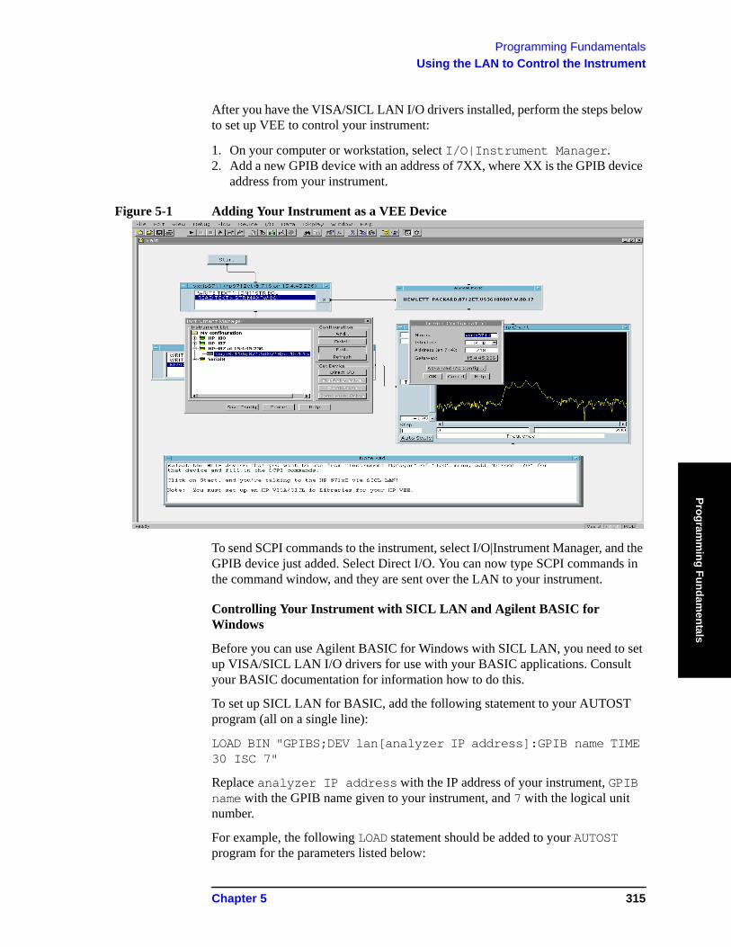
Programming FundamentalsUsing the LAN to Control the Instrument
Programm
ing Fundamentals
After you have the VISA/SICL LAN I/O drivers installed, perform the steps below to set up VEE to control your instrument:
1. On your computer or workstation, select I/O|Instrument Manager.2. Add a new GPIB device with an address of 7XX, where XX is the GPIB device
address from your instrument.
Figure 5-1 Adding Your Instrument as a VEE Device
To send SCPI commands to the instrument, select I/O|Instrument Manager, and the GPIB device just added. Select Direct I/O. You can now type SCPI commands in the command window, and they are sent over the LAN to your instrument.
Controlling Your Instrument with SICL LAN and Agilent BASIC for Windows
Before you can use Agilent BASIC for Windows with SICL LAN, you need to set up VISA/SICL LAN I/O drivers for use with your BASIC applications. Consult your BASIC documentation for information how to do this.
To set up SICL LAN for BASIC, add the following statement to your AUTOST program (all on a single line):
LOAD BIN "GPIBS;DEV lan[analyzer IP address]:GPIB name TIME 30 ISC 7"
Replace analyzer IP address with the IP address of your instrument, GPIB name with the GPIB name given to your instrument, and 7 with the logical unit number.
For example, the following LOAD statement should be added to your AUTOST program for the parameters listed below:
Chapter 5 315
Programming FundamentalsUsing the LAN to Control the Instrument
Prog
ram
min
g Fu
ndam
enta
ls
instrument IP address 191.108.344.225
instrument GPIB name inst0
logical unit number 7
timeout value (seconds) 30
LOAD statement (all on a single line)
LOAD BIN “GPIBS;DEV lan[191.108.344.225]:inst0 TIME 30 ISC 7”
Consult your BASIC documentation to learn how to load the SICL driver for BASIC.
After the SICL driver is loaded, you control your instrument using commands such as the following:
OUTPUT 718; "*IDN?" ENTER 718; S$
where 18 is the device address for the instrument.
See the BASIC example program in this chapter for more information.
Controlling Your Instrument with SICL LAN and BASIC for UNIX (Rocky Mountain BASIC)
Before you can use Rocky Mountain Basic (HPRMB) with SICL LAN, you will need to set up the SICL LAN I/O drivers for HPRMB. Consult your system administrator for details.
Create a .rmbrc file in your root directory of your UNIX workstation with the following entries:
SELECTIVE_OPEN=ON Interface 8= "lan[analyzer IP address]:GPIB name";NORMAL
Replace analyzer IP address with the IP address of your instrument, and GPIB name with the GPIB name given to your instrument. Also replace the “8” of Interface 8 with the logical unit number. Consult your HPRMB documentation for the exact syntax.
After your SICL driver is configured correctly on your UNIX workstation, you control your instrument using commands such as the following:
OUTPUT 818; "*IDN?" ENTER 818; S$
where 18 is the device address for the instrument.
316 Chapter 5
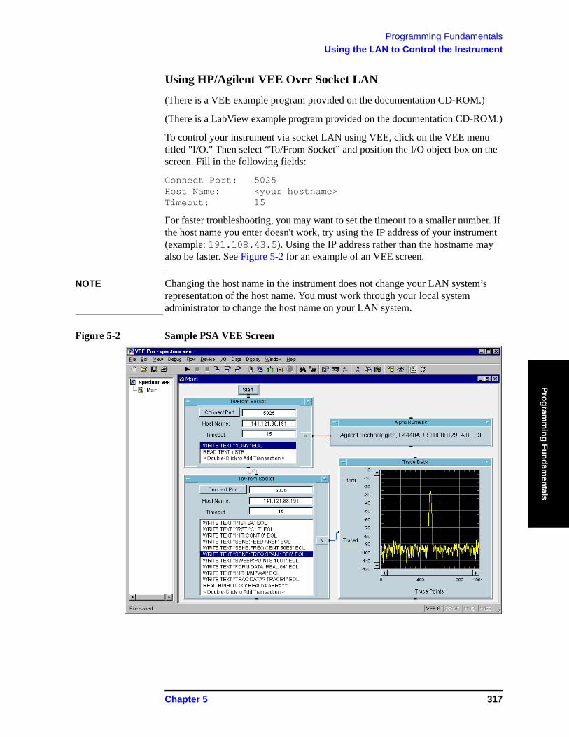
Programming FundamentalsUsing the LAN to Control the Instrument
Programm
ing Fundamentals
Using HP/Agilent VEE Over Socket LAN
(There is a VEE example program provided on the documentation CD-ROM.)
(There is a LabView example program provided on the documentation CD-ROM.)
To control your instrument via socket LAN using VEE, click on the VEE menu titled "I/O." Then select “To/From Socket” and position the I/O object box on the screen. Fill in the following fields:
Connect Port: 5025 Host Name: <your_hostname> Timeout: 15
For faster troubleshooting, you may want to set the timeout to a smaller number. If the host name you enter doesn't work, try using the IP address of your instrument (example: 191.108.43.5). Using the IP address rather than the hostname may also be faster. See Figure 5-2 for an example of an VEE screen.
NOTE Changing the host name in the instrument does not change your LAN system’s representation of the host name. You must work through your local system administrator to change the host name on your LAN system.
Figure 5-2 Sample PSA VEE Screen
Chapter 5 317
Programming FundamentalsUsing the LAN to Control the Instrument
Prog
ram
min
g Fu
ndam
enta
ls
Using a Java™ Applet Over Socket LAN
There is a programming example in the PSA Measurement Guide and Programming Examples that demonstrates simple socket programming with Java. It is written in Java programming language, and will compile with Java compilers versions 1.0 and above.
This program is also on the documentation CD ROM that shipped with your product.
Using a C Program Over Socket LAN
The PSA Measurement Guide and Programming Examples book contains two examples of simple LAN socket programs. They are written in C. One compiles in the HP-UX UNIX environment and one is written for the WIN32 environment.
In UNIX, LAN communication via sockets is very similar to reading or writing a file. The only difference is the openSocket() routine, which uses a few network library routines to create the TCP/IP network connection. Once this connection is created, the standard fread() and fwrite() routines are used for network communication.
In Windows, the routines send() and recv() must be used, because fread() and fwrite() may not work on sockets.
NOTE You may need to enable the termination character attribute when using the VISA libraries for socket communication. If the termchar attribute is disabled, then no termination character is sent with the data and the bus will time out waiting for it. (Set vi_attr_termchar_en)
General LAN Troubleshooting
• “Troubleshooting the Initial Connection” on page 5-318• “Common Problems After a Connection is Made” on page 5-320• “Pinging the Instrument from a Computer or Workstation” on page 5-321• “EIA/TIA 568B Wiring Information” on page 5-324
Troubleshooting the Initial Connection
Getting the instrument to work with your network often requires detailed knowledge of your local network software. This section attempts to help you with some common problems. Contact your network administrator for additional assistance.
The instrument LAN interface does not need or include any proprietary driver software. It was designed to operate with common network utilities and drivers.
Either a hardware problem or a software problem can prevent the instrument's remote file server from communicating over the LAN. The following common problems may be encountered:
Communications Not Established
318 Chapter 5
Programming FundamentalsUsing the LAN to Control the Instrument
Programm
ing Fundamentals
If you have just installed and configured the LAN interface and you have never been able to access the instrument via ftp or telnet, go directly to “Pinging the Instrument from a Computer or Workstation” on page 5-321.
If you have previously been able to access the instrument via ftp or telnet and now cannot do so, check the following:
o Has any hardware been added or moved on your network? This includes adding or removing any workstations or peripherals, or changing any cabling.
o Have software applications been added to the network?
o Has the functionality been turned off from the front panel? Press System, Config I/O, SCPI LAN.
o Have any configuration files been modified? Pressing System, Restore Sys Defaults restores the original factory defaults and you will have to re-set the instrument IP address and host name.
o Is the upper- and lower-case character usage in your host name consistent?
o Have any of the following files been deleted or overwritten?
UNIX:
— /etc/hosts
— /etc/inetd.conf
— /etc/services
PCs:
— dependent network files
If you know or suspect that something has changed on your network, consult with your network administrator.
Timeout Errors
Timeout errors such as “Device Timeout,” “File Timeout,” and “Operation Timeout,” are symptoms of one or both of the following problems:
— The currently configured timeout limits are too short compared to the time it takes the LAN to complete some operations. This problem may occur during periods of increased LAN traffic.
— The LAN connection has failed, or fails occasionally.
To increase your timeout period, refer to your computer documentation for instructions. Contact your LAN administrator if problems continue.
Packets Routinely Lost
If packets are routinely lost, proceed to the troubleshooting section in this chapter relating to your network.
Problems Transferring or Copying Files
Chapter 5 319

Programming FundamentalsUsing the LAN to Control the Instrument
Prog
ram
min
g Fu
ndam
enta
ls
If you have problems copying files out of or into the instrument, you might be experiencing timeout problems. See the previous section on “Timeout Errors.”
Common Problems After a Connection is Made
This section describes common problems you may encounter when using the instrument on a LAN. It assumes you have been able to connect to the instrument in the past. If this is not so, refer to the previous sections first.
NOTE Pressing Preset does not affect LAN settings, but pressing System, Restore Sys Defaults will reset to the original factory defaults. You will then have to re-set the instrument IP address and other LAN settings in System, Config I/O.
NOTE Remember that in any type of programming using LAN you should avoid constantly opening and closing connections. This uses up processing resources, adds to your system overhead, and can cause problems with asynchronous implementation of successive commands. When you are sending the instrument multiple commands: open the connection, send all the commands, and close the connection.
Cannot connect to the analyzer
• If you suspect a bad LAN connection between your computer and instrument, you can verify the network connection by using the ping command described later in this chapter or another similar echo request utility.
• If a bad connection is revealed, try the following solutions:
— Make sure the instrument is turned on.
— Check the physical connection to the LAN.
— Make sure the internet (IP) Address of the instrument is set up correctly in the LAN port setup menu. (Press System, Config I/O, IP Address.)
— When connecting to your instrument over a closed network (directly through a hub or crossover cable) it may help to set the instrument to its default settings for subnet mask and gateway. (subnet mask: 255.255.0.0, gateway 0.0.0.0)
— If the instrument and the computer are on different networks or subnets, make sure the gateway address and subnet mask values are set correctly.
Cannot access the file system via ftp
• If you get a "connection refused" message, try the following solutions:
— If the power to the instrument was just turned on, make sure that you wait about 25 seconds before attempting the connection.
• If you get a "connection timed out" message
— Verify the LAN connection between your computer and the instrument.
320 Chapter 5

Programming FundamentalsUsing the LAN to Control the Instrument
Programm
ing Fundamentals
Refer to "If you cannot connect to the instrument" earlier in this section.
Cannot telnet to the command parser port
• For a "connection refused" message
— Check the telnet port number from the front panel keys.
• For a "connection timed out" or "no response from host" message
— Verify the LAN connection between your computer and the instrument. Refer to "If you cannot connect to the instrument" earlier in this section.
• For a "connection refused" or "no response from host" message
— If the instrument was just turned on, make sure that you wait about 25 seconds before attempting the connection.
An "operation timed-out" message
• Check the LAN connection between the computer and the instrument. Refer to "If you cannot connect to the instrument" in this section.
• Increase the file time-out value on your PC or workstation.
Cannot access internal web pages or import graphic images when using a point-to-point connection
• Disable the use of proxy servers. You may have to specify this in a number of locations, depending on the operating system and software you are using.
• Disable the use of cached copies of web pages to ensure that you always get a new copy of the instrument’s screen image.
If all else fails
• Contact your network administrator.
• If you still cannot solve the problem, contact an Agilent Service Center for repair information.
Pinging the Instrument from a Computer or Workstation
Verify the communications link between the computer and the instrument remote file server using the ping utility.
From a UNIX workstation, type:
ping hostname 64 10
where 64 is the packet size, and 10 is the number of packets transmitted.
From a DOS or Windows environment, type:
ping hostname 10
where 10 is the number of echo requests.
Normal Response for UNIX
Chapter 5 321
Programming FundamentalsUsing the LAN to Control the Instrument
Prog
ram
min
g Fu
ndam
enta
ls
A normal response to the ping will be a total of 9, 10, or possibly 11 packets received with a minimal average round-trip time. The minimal average will be different from network to network. LAN traffic will cause the round-trip time to vary widely.
Because the number of packets received depends on your network traffic and integrity, the normal number might be different for your network.
Normal Response for DOS or Windows
A normal response to the ping will be a total of 9, 10, or possibly 11 packets received if 10 echo requests were specified.
Because the number of packets received depends on your network traffic and integrity, the normal number might be different for your network.
Error Messages
If error messages appear, then check the command syntax before continuing with the troubleshooting. If the syntax is correct, then resolve the error messages using your network documentation, or by consulting your network administrator.
If an unknown host error message appears, then check that the host name and IP address for your instrument are correctly entered from the front panel. Press System, Config I/O.
322 Chapter 5
Programming FundamentalsUsing the LAN to Control the Instrument
Programm
ing Fundamentals
No Response No packets received indicates no response from a ping.
If there is no response, try typing in the IP address with the ping command, instead of using the host name. Check that the typed address matches the IP address assigned in the System, Config I/O menu, then check the other addresses in the menu.
Check that the host name and IP address are correctly entered in the node names database.
If you are using a UNIX environment, ping each node along the route between your workstation and the instrument, starting with the your workstation. Ping each gateway, then attempt a ping of the remote file server.
If the instrument still does not respond to ping, then you should suspect a hardware problem with the instrument. To check the instrument performance, refer to "Verify the Instrument Performance" in this chapter.
Intermittent Response
If you received 1 to 8 packets back, there is probably a problem with the network. Because the number of packets received depends on your network traffic and integrity, the number might be different for your network.
Use a LAN analyzer or LAN management software to monitor activity and determine where bottlenecks or other problems are occurring. The instrument will still function, but communications over the LAN will be slower.
On a single-client/single-server network, the most likely cause of intermittent response to an echo request is a hardware problem with the LAN module installed in the PC, the cable, or the instrument. To check the instrument, refer to "Verify the Instrument Performance" later in this chapter.
The Standard UNIX PING Command Synopsis ping [-r] [-v] [-o] host [packetsize] [count]
Description The ping command sends an echo request packet to the host once per second. Each echo response packet that is returned is listed on the screen, along with the round-trip time of the echo request and echo response.
Options and Parameters -r Bypasses the routing tables, and sends the request directly to the host.
-v Reports all packets that are received, including the response packets.
-o Requests information about the network paths taken by the requests and responses.
host The host name or IP address.
packetsize The size of each packet (8 bytes - 4096 bytes).
count The number of packets to send before ending ping (1-(231-1)). If count is not specified, ping sends packets until interrupted.
Chapter 5 323
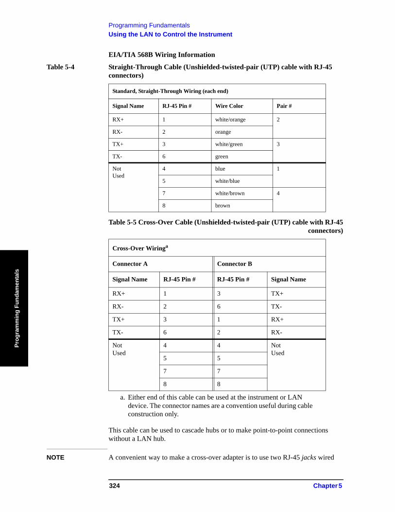
Programming FundamentalsUsing the LAN to Control the Instrument
Prog
ram
min
g Fu
ndam
enta
ls
EIA/TIA 568B Wiring Information
This cable can be used to cascade hubs or to make point-to-point connections without a LAN hub.
NOTE A convenient way to make a cross-over adapter is to use two RJ-45 jacks wired
Table 5-4 Straight-Through Cable (Unshielded-twisted-pair (UTP) cable with RJ-45 connectors)
Standard, Straight-Through Wiring (each end)
Signal Name RJ-45 Pin # Wire Color Pair #
RX+ 1 white/orange 2
RX- 2 orange
TX+ 3 white/green 3
TX- 6 green
Not Used
4 blue 1
5 white/blue
7 white/brown 4
8 brown
Table 5-5 Cross-Over Cable (Unshielded-twisted-pair (UTP) cable with RJ-45 connectors)
Cross-Over Wiringa
Connector A Connector B
Signal Name RJ-45 Pin # RJ-45 Pin # Signal Name
RX+ 1 3 TX+
RX- 2 6 TX-
TX+ 3 1 RX+
TX- 6 2 RX-
Not Used
4 4 Not Used
5 5
7 7
8 8
a. Either end of this cable can be used at the instrument or LAN device. The connector names are a convention useful during cable construction only.
324 Chapter 5
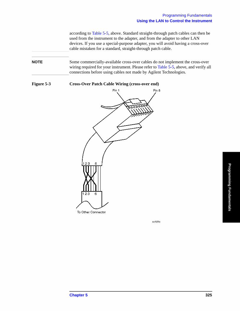
Programming FundamentalsUsing the LAN to Control the Instrument
Programm
ing Fundamentals
according to Table 5-5, above. Standard straight-through patch cables can then be used from the instrument to the adapter, and from the adapter to other LAN devices. If you use a special-purpose adapter, you will avoid having a cross-over cable mistaken for a standard, straight-through patch cable.
NOTE Some commercially-available cross-over cables do not implement the cross-over wiring required for your instrument. Please refer to Table 5-5, above, and verify all connections before using cables not made by Agilent Technologies.
Figure 5-3 Cross-Over Patch Cable Wiring (cross-over end)
Chapter 5 325
Programming FundamentalsProgramming in C Using the VTL
Prog
ram
min
g Fu
ndam
enta
ls
Programming in C Using the VTLThe programming examples that are provided are written using the C programming language and the Agilent VTL (VISA transition library). This section includes some basic information about programming in the C language. Note that some of this information may not be relevant to your particular application. (For example, if you are not using VXI instruments, the VXI references will not be relevant).
Refer to your C programming language documentation for more details. (This information is taken from the manual “VISA Transition Library”, part number E2090-90026.) The following topics are included:
“Typical Example Program Contents” on page 326
“Linking to VTL Libraries” on page 327
“Compiling and Linking a VTL Program” on page 327
“Example Program” on page 329
“Including the VISA Declarations File” on page 329
“Opening a Session” on page 330
“Device Sessions” on page 330
“Addressing a Session” on page 332
“Closing a Session” on page 333
Typical Example Program Contents
The following is a summary of the VTL function calls used in the example programs.
visa.h This file is included at the beginning of the file to provide the function prototypes and constants defined by VTL.
ViSession The ViSession is a VTL data type. Each object that will establish a communication channel must be defined as ViSession.
viOpenDefaultRM You must first open a session with the default resource manager with the viOpenDefaultRM function. This function will initialize the default resource manager and return a pointer to that resource manager session.
viOpen This function establishes a communication channel with the device specified. A session identifier that can be used with other VTL functions is returned. This call must be made for each device you will be using.
326 Chapter 5
Programming FundamentalsProgramming in C Using the VTL
Programm
ing Fundamentals
viPrintf viScanf These are the VTL formatted I/O functions that are patterned
after those used in the C programming language. The viPrintf call sends the IEEE 488.2 *RST command to the instrument and puts it in a known state. The viPrintf call is used again to query for the device identification (*IDN?). The viScanf call is then used to read the results.
viClose This function must be used to close each session. When you close a device session, all data structures that had been allocated for the session will be de-allocated. When you close the default manager session, all sessions opened using the default manager session will be closed.
Linking to VTL Libraries
Your application must link to one of the VTL import libraries:
32-bit Version:
C:\VXIPNP\WIN95\LIB\MSC\VISA32.LIB for Microsoft compilers
C:\VXIPNP\WIN95\LIB\BC\VISA32.LIB for Borland compilers
16-bit Version:
C:\VXIPNP\WIN\LIB\MSC\VISA.LIB for Microsoft compilers
C:\VXIPNP\WIN\LIB\BC\VISA.LIB for Borland compilers
See the following section, “Compiling and Linking a VTL Program” for information on how to use the VTL run-time libraries.
Compiling and Linking a VTL Program
32-bit Applications
The following is a summary of important compiler-specific considerations for several C/C++ compiler products when developing WIN32 applications.
For Microsoft Visual C++ version 2.0 compilers:
• Select Project | Update All Dependencies from the menu.
• Select Project | Settings from the menu. Click on the C/C++ button. Select Code Generation from the Use Run-Time Libraries list box. VTL requires these definitions for WIN32. Click on OK to close the dialog boxes.
• Select Project | Settings from the menu. Click on the Link button and add visa32.lib to the Object / Library Modules list box. Optionally, you may add the library directly to your project file. Click on OK to close the dialog boxes.
• You may wish to add the include file and library file search paths. They are set
Chapter 5 327
Programming FundamentalsProgramming in C Using the VTL
Prog
ram
min
g Fu
ndam
enta
ls
by doing the following:
1. Select Tools | Options from the menu.
2. Click on the Directories button to set the include file path.
3. Select Include Files from the Show Directories For list box.
4. Click on the Add button and type in the following: C:\VXIPNP\WIN95\INCLUDE
5. Select Library Files from the Show Directories For list box.
6. Click on the Add button and type in the following: C:\VXIPNP\WIN95\LIB\MSC
For Borland C++ version 4.0 compilers:
• You may wish to add the include file and library file search paths. They are set under the Options | Project menu selection. Double click on Directories from the Topics list box and add the following:
C:\VXIPNP\WIN95\INCLUDE C:\VXIPNP\WIN95\LIB\BC
16-bit Applications
The following is a summary of important compiler-specific considerations for the Windows compiler.
For Microsoft Visual C++ version 1.5:
• To set the memory model, do the following:
1. Select Options | Project.
2. Click on the Compiler button, then select Memory Model from the Category list.
3. Click on the Model list arrow to display the model options, and select Large.
4. Click on OK to close the Compiler dialog box.
• You may wish to add the include file and library file search paths. They are set under the Options | Directories menu selection:
C:\VXIPNP\WIN\INCLUDE C:\VXIPNP\WIN\LIB\MSC
Otherwise, the library and include files should be explicitly specified in the project file.
328 Chapter 5
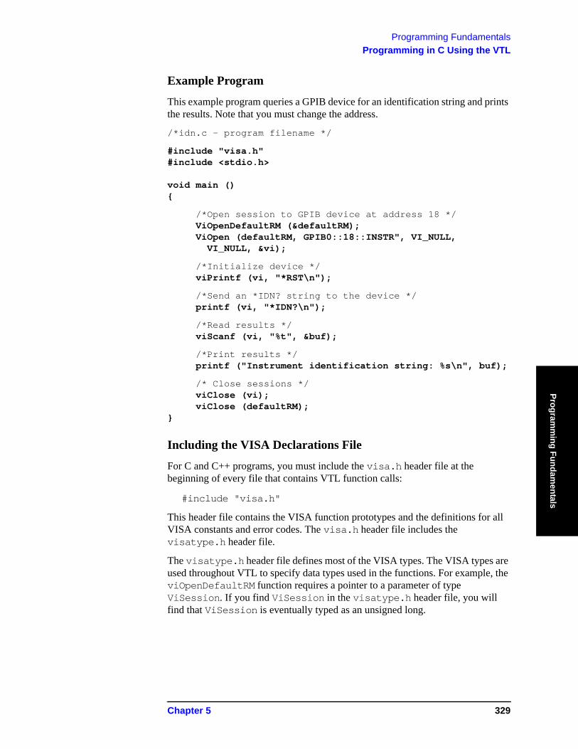
Programming FundamentalsProgramming in C Using the VTL
Programm
ing Fundamentals
Example Program
This example program queries a GPIB device for an identification string and prints the results. Note that you must change the address.
/*idn.c - program filename */
#include "visa.h" #include <stdio.h> void main () {
/*Open session to GPIB device at address 18 */ ViOpenDefaultRM (&defaultRM); ViOpen (defaultRM, GPIB0::18::INSTR", VI_NULL, VI_NULL, &vi);
/*Initialize device */ viPrintf (vi, "*RST\n");
/*Send an *IDN? string to the device */ printf (vi, "*IDN?\n");
/*Read results */ viScanf (vi, "%t", &buf);
/*Print results */ printf ("Instrument identification string: %s\n", buf);
/* Close sessions */ viClose (vi); viClose (defaultRM); }
Including the VISA Declarations File
For C and C++ programs, you must include the visa.h header file at the beginning of every file that contains VTL function calls:
#include "visa.h"
This header file contains the VISA function prototypes and the definitions for all VISA constants and error codes. The visa.h header file includes the visatype.h header file.
The visatype.h header file defines most of the VISA types. The VISA types are used throughout VTL to specify data types used in the functions. For example, the viOpenDefaultRM function requires a pointer to a parameter of type ViSession. If you find ViSession in the visatype.h header file, you will find that ViSession is eventually typed as an unsigned long.
Chapter 5 329
Programming FundamentalsProgramming in C Using the VTL
Prog
ram
min
g Fu
ndam
enta
ls
Opening a Session
A session is a channel of communication. Sessions must first be opened on the default resource manager, and then for each device you will be using. The following is a summary of sessions that can be opened:
• A resource manager session is used to initialize the VISA system. It is a parent session that knows about all the opened sessions. A resource manager session must be opened before any other session can be opened.
• A device session is used to communicate with a device on an interface. A device session must be opened for each device you will be using. When you use a device session you can communicate without worrying about the type of interface to which it is connected. This insulation makes applications more robust and portable across interfaces. Typically a device is an instrument, but could be a computer, a plotter, or a printer.
NOTE All devices that you will be using need to be connected and in working condition prior to the first VTL function call (viOpenDefaultRM). The system is configured only on the first viOpenDefaultRM per process. Therefore, if viOpenDefaultRM is called without devices connected and then called again when devices are connected, the devices will not be recognized. You must close ALL resource manager sessions and re-open with all devices connected and in working condition.
Device Sessions
There are two parts to opening a communications session with a specific device. First you must open a session to the default resource manager with the viOpenDefaultRM function. The first call to this function initializes the default resource manager and returns a session to that resource manager session. You only need to open the default manager session once. However, subsequent calls to viOpenDefaultRM returns a session to a unique session to the same default resource manager resource.
Next, you open a session with a specific device with the viOpen function. This function uses the session returned from viOpenDefaultRM and returns its own session to identify the device session. The following shows the function syntax:
viOpenDefaultRM (sesn);
viOpen (sesn, rsrcName, accessMode, timeout, vi);
The session returned from viOpenDefaultRM must be used in the sesn parameter of the viOpen function. The viOpen function then uses that session and the device address specified in the rsrcName parameter to open a device session. The vi parameter in viOpen returns a session identifier that can be used with other VTL functions.
Your program may have several sessions open at the same time by creating multiple session identifiers by calling the viOpen function multiple times.
The following summarizes the parameters in the previous function calls:
330 Chapter 5
Programming FundamentalsProgramming in C Using the VTL
Programm
ing Fundamentals
sesn This is a session returned from the viOpenDefaultRM function that identifies the resource manager session.
rsrcName This is a unique symbolic name of the device (device address).
accessMode This parameter is not used for VTL. Use VI_NULL.
timeout This parameter is not used for VTL. Use VI_NULL.
vi This is a pointer to the session identifier for this particular device session. This pointer will be used to identify this device session when using other VTL functions.
The following is an example of opening sessions with a GPIB multimeter and a GPIB-VXI scanner:
ViSession defaultRM, dmm, scanner; . . viOpenDefaultRM(&defaultRM); viOpen (defaultRM, "GPIB0::22::INSTR", VI_NULL, VI_NULL, &dmm); viOpen (defaultRM, "GPIB-VXI0::24::INSTR", VI_NULL, VI_NULL, &scanner); . . viClose (scanner); viClose (dmm); viClose(defaultRM);
The above function first opens a session with the default resource manager. The session returned from the resource manager and a device address is then used to open a session with the GPIB device at address 22. That session will now be identified as dmm when using other VTL functions. The session returned from the resource manager is then used again with another device address to open a session with the GPIB-VXI device at primary address 9 and VXI logical address 24. That session will now be identified as scanner when using other VTL functions. See the following section for information on addressing particular devices.
Chapter 5 331
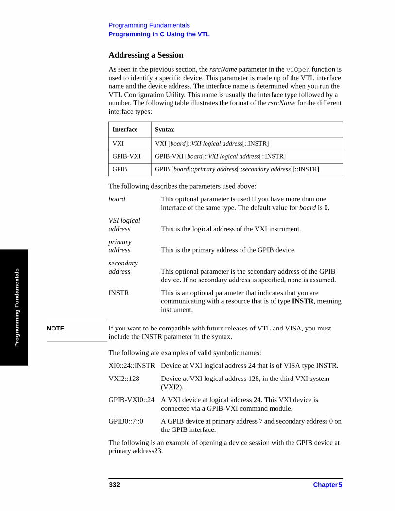
Programming FundamentalsProgramming in C Using the VTL
Prog
ram
min
g Fu
ndam
enta
ls
Addressing a Session
As seen in the previous section, the rsrcName parameter in the viOpen function is used to identify a specific device. This parameter is made up of the VTL interface name and the device address. The interface name is determined when you run the VTL Configuration Utility. This name is usually the interface type followed by a number. The following table illustrates the format of the rsrcName for the different interface types:
The following describes the parameters used above:
board This optional parameter is used if you have more than one interface of the same type. The default value for board is 0.
VSI logical address This is the logical address of the VXI instrument.
primary address This is the primary address of the GPIB device.
secondary address This optional parameter is the secondary address of the GPIB
device. If no secondary address is specified, none is assumed.
INSTR This is an optional parameter that indicates that you are communicating with a resource that is of type INSTR, meaning instrument.
NOTE If you want to be compatible with future releases of VTL and VISA, you must include the INSTR parameter in the syntax.
The following are examples of valid symbolic names:
XI0::24::INSTR Device at VXI logical address 24 that is of VISA type INSTR.
VXI2::128 Device at VXI logical address 128, in the third VXI system (VXI2).
GPIB-VXI0::24 A VXI device at logical address 24. This VXI device is connected via a GPIB-VXI command module.
GPIB0::7::0 A GPIB device at primary address 7 and secondary address 0 on the GPIB interface.
The following is an example of opening a device session with the GPIB device at primary address23.
Interface Syntax
VXI VXI [board]::VXI logical address[::INSTR]
GPIB-VXI GPIB-VXI [board]::VXI logical address[::INSTR]
GPIB GPIB [board]::primary address[::secondary address][::INSTR]
332 Chapter 5
Programming FundamentalsProgramming in C Using the VTL
Programm
ing Fundamentals
ViSession defaultRM, vi;
.
.
viOpenDefaultRM (&defaultRM);
viOpen (defaultRM, "GPIB0::23::INSTR", VI_NULL,VI_NULL,&vi);
.
.
viClose(vi);
viClose (defaultRM);
Closing a Session
The viClose function must be used to close each session. You can close the specific device session, which will free all data structures that had been allocated for the session. If you close the default resource manager session, all sessions opened using that resource manager will be closed.
Since system resources are also used when searching for resources (viFindRsrc) or waiting for events (viWaitOnEvent), the viClose function needs to be called to free up find lists and event contexts.
Chapter 5 333
Programming FundamentalsOverview of the GPIB Bus
Prog
ram
min
g Fu
ndam
enta
ls
Overview of the GPIB BusAn instrument that is part of a GPIB network is categorized as a listener, talker, or controller, depending on its current function in the network.
Listener A listener is a device capable of receiving data or commands from other instruments. Any number of instruments in the GPIB network can be listeners simultaneously.
Talker A talker is a device capable of transmitting data or commands to other instruments. To avoid confusion, a GPIB system allows only one device at a time to be an active talker.
Controller A controller is an instrument, typically a computer, capable of managing the various GPIB activities. Only one device at a time can be an active controller.
GPIB Command Statements
Command statements form the nucleus of GPIB programming. They are understood by all instruments in the network. When combined with the programming language codes, they provide all management and data communication instructions for the system. Refer to the your programming language manual and your computers I/O programming manual for more information.
The seven fundamental command functions are as follows:
• An abort function that stops all listener/talker activity on the interface bus, and prepares all instruments to receive a new command from the controller. Typically, this is an initialization command used to place the bus in a known starting condition (sometimes called: abort, abortio, reset, halt).
• A remote function that causes an instrument to change from local control to remote control. In remote control, the front panel keys are disabled except for the Local key and the line power switch (sometimes called: remote, resume).
• A local lockout function, that can be used with the remote function, to disable the front panel Local key. With the Local key disabled, only the controller (or a hard reset by the line power switch) can restore local control (sometimes called: local lockout).
• A local function that is the complement to the remote command, causing an instrument to return to local control with a fully enabled front panel (sometimes called: local, resume).
• A clear function that causes all GPIB instruments, or addressed instruments, to assume a cleared condition. The definition of clear is unique for each instrument (sometimes called: clear, reset, control, send).
• An output function that is used to send function commands and data commands from the controller to the addressed instrument (sometimes called: output,
334 Chapter 5
Programming FundamentalsOverview of the GPIB Bus
Programm
ing Fundamentals
control, convert, image, iobuffer, transfer).• An enter function that is the complement of the output function and is used to
transfer data from the addressed instrument to the controller (sometimes called: enter, convert, image, iobuffer, on timeout, set timeout, transfer).
Chapter 5 335

Programming FundamentalsOverview of the GPIB Bus
Prog
ram
min
g Fu
ndam
enta
ls
336 Chapter 5
Using the STATus System
6 Using the STATus System
When you are programming the instrument you may need to monitor instrument status to check for error conditions or monitor changes. You can determine the state of certain instrument events or conditions by programming the status register system. IEEE common commands (those beginning with *) access the higher-level summary registers. To access the information from specific registers, you would use the STATus commands.
337
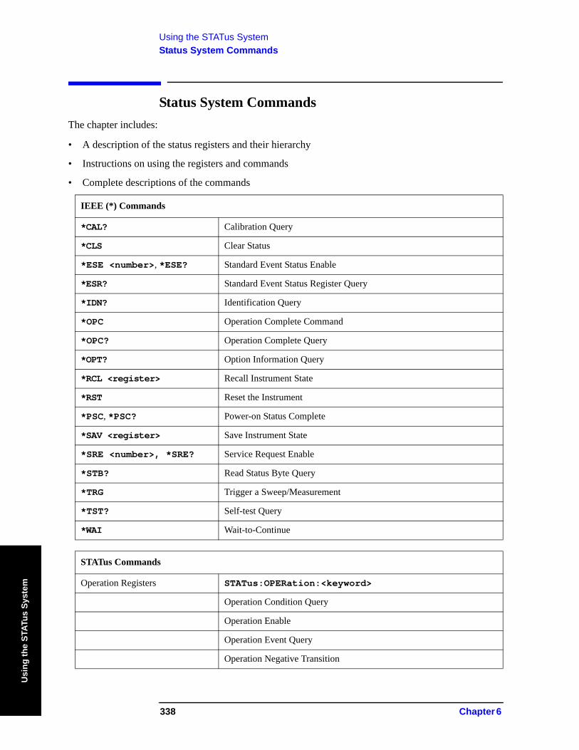
Using the STATus SystemStatus System Commands
Usi
ng th
e ST
ATus
Sys
tem
Status System CommandsThe chapter includes:
• A description of the status registers and their hierarchy
• Instructions on using the registers and commands
• Complete descriptions of the commands
IEEE (*) Commands
*CAL? Calibration Query
*CLS Clear Status
*ESE <number>, *ESE? Standard Event Status Enable
*ESR? Standard Event Status Register Query
*IDN? Identification Query
*OPC Operation Complete Command
*OPC? Operation Complete Query
*OPT? Option Information Query
*RCL <register> Recall Instrument State
*RST Reset the Instrument
*PSC, *PSC? Power-on Status Complete
*SAV <register> Save Instrument State
*SRE <number>, *SRE? Service Request Enable
*STB? Read Status Byte Query
*TRG Trigger a Sweep/Measurement
*TST? Self-test Query
*WAI Wait-to-Continue
STATus Commands
Operation Registers STATus:OPERation:<keyword>
Operation Condition Query
Operation Enable
Operation Event Query
Operation Negative Transition
338 Chapter 6
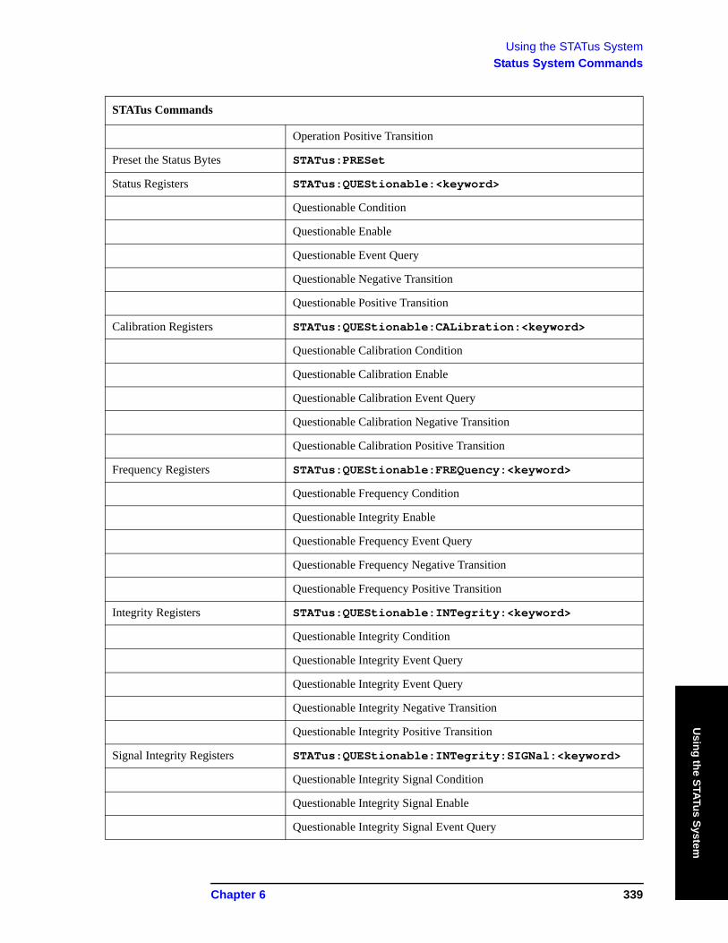
Using the STATus SystemStatus System Commands
Using the STATus System
Operation Positive Transition
Preset the Status Bytes STATus:PRESet
Status Registers STATus:QUEStionable:<keyword>
Questionable Condition
Questionable Enable
Questionable Event Query
Questionable Negative Transition
Questionable Positive Transition
Calibration Registers STATus:QUEStionable:CALibration:<keyword>
Questionable Calibration Condition
Questionable Calibration Enable
Questionable Calibration Event Query
Questionable Calibration Negative Transition
Questionable Calibration Positive Transition
Frequency Registers STATus:QUEStionable:FREQuency:<keyword>
Questionable Frequency Condition
Questionable Integrity Enable
Questionable Frequency Event Query
Questionable Frequency Negative Transition
Questionable Frequency Positive Transition
Integrity Registers STATus:QUEStionable:INTegrity:<keyword>
Questionable Integrity Condition
Questionable Integrity Event Query
Questionable Integrity Event Query
Questionable Integrity Negative Transition
Questionable Integrity Positive Transition
Signal Integrity Registers STATus:QUEStionable:INTegrity:SIGNal:<keyword>
Questionable Integrity Signal Condition
Questionable Integrity Signal Enable
Questionable Integrity Signal Event Query
STATus Commands
Chapter 6 339
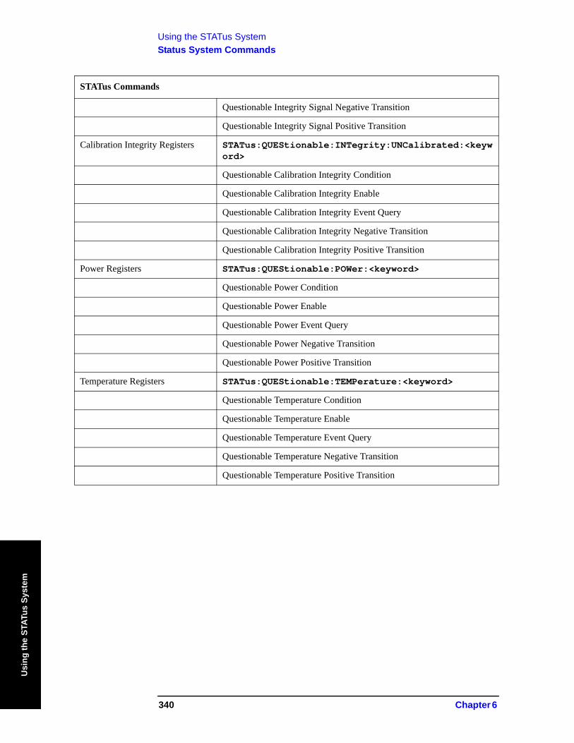
Using the STATus SystemStatus System Commands
Usi
ng th
e ST
ATus
Sys
tem
Questionable Integrity Signal Negative Transition
Questionable Integrity Signal Positive Transition
Calibration Integrity Registers STATus:QUEStionable:INTegrity:UNCalibrated:<keyword>
Questionable Calibration Integrity Condition
Questionable Calibration Integrity Enable
Questionable Calibration Integrity Event Query
Questionable Calibration Integrity Negative Transition
Questionable Calibration Integrity Positive Transition
Power Registers STATus:QUEStionable:POWer:<keyword>
Questionable Power Condition
Questionable Power Enable
Questionable Power Event Query
Questionable Power Negative Transition
Questionable Power Positive Transition
Temperature Registers STATus:QUEStionable:TEMPerature:<keyword>
Questionable Temperature Condition
Questionable Temperature Enable
Questionable Temperature Event Query
Questionable Temperature Negative Transition
Questionable Temperature Positive Transition
STATus Commands
340 Chapter 6
Using the STATus SystemUsing the Status Registers
Using the STATus System
6.1 Using the Status RegistersThe Section “PSA Core Status Register System (Page 1 of 2)” on page 347 shows the PSA instrument status registers and their hierarchy. Note that some measurement personality Modes use the E4406A status register design instead of the PSA design. (These include Basic Mode, NADC/PDC, GSM/EDGE, cdmaOne, cdma2000/1xEV-DV, W-CDMA/HSDPA and 1xEV-DO.)
• “What Status Registers Are” on page 341• “How to Use the Status Registers” on page 342• “Using a Status Register” on page 344• “Using the Service Request (SRQ) Method” on page 345• “PSA Core Status Register System (Page 1 of 2)” on page 347• “Standard Event Status Register” on page 353• “Operation and Questionable Status Registers” on page 355
6.1.1 What Status Registers Are
The status system is comprised of multiple registers that are arranged in a hierarchical order. The lower-level status registers propagate their data to the higher-level registers in the data structures by means of summary bits. The status byte register is at the top of the hierarchy and contains general status information for the instrument’s events and conditions. All other individual registers are used to determine the specific events or conditions.
The operation and questionable status registers are sets of registers that monitor the overall instrument condition. They are accessed with the STATus:OPERation and STATus:QUEStionable commands in the STATus command subsystem. Each register set is made up of five registers:
Condition Register it reports the real-time state of the signals monitored by this register set.There is no latching or buffering for a condition register.
Positive Transition Register this filter register controls which signals will set a bit in the event register when the signal makes a low to high transition (when the condition bit changes from 0 to 1).
Negative Transition Register this filter register controls which signals will set a bit in the event register when the signal makes a high to low transition (when the condition bit changes from 1 to 0).
Event Register it latches any signal state changes, in the way specified by the filter registers. Bits in the event register are never cleared by signal state changes. Event registers are cleared when read. They are also cleared by *CLS and by presetting the instrument.
Event Enable Register it controls which of the bits, being set in the event register, will be summarized as a single output for the register set. Summary bits are then used by the next higher register.
Chapter 6 341
Using the STATus SystemUsing the Status Registers
Usi
ng th
e ST
ATus
Sys
tem
The STATus:QUEStionable registers report abnormal operating conditions. The status register hierarchy is:
1. The summary outputs from the six STATus:QUEStionable:<keyword> detail registers are inputs to the STATus:QUEStionable register.
2. The summary output from the STATus:QUEStionable register is an input to the Status Byte Register. See the Section “PSA Core Status Register System (Page 1 of 2)” on page 347.
The STATus:OPERation register set has no summarized inputs. The inputs to the STATus:OPERation:CONDition register indicate the real time state of the instrument. The STATus:OPERation:EVENt register summary output is an input to the Status Byte Register.
6.1.1.1 What Status Register SCPI Commands Are
Most monitoring of the instrument conditions is done at the highest level using the IEEE common commands indicated below. Complete command descriptions are available in the IEEE commands section at the beginning of the language reference. Individual status registers can be set and queried using the commands in the STATus subsystem of the language reference.
*CLS (clear status) clears the status byte by emptying the error queue and clearing all the event registers.
*ESE, *ESE? (event status enable) sets and queries the bits in the enable register part of the standard event status register.
*ESR? (event status register) queries and clears the event register part of the standard event status register.
*OPC, *OPC? (operation complete) sets the standard event status register to monitor the completion of all commands. The query stops any new commands from being processed until the current processing is complete, then returns a ‘1’.
*PSC, *PSC? (power-on state clear) sets the power-on state so that it clears the service request enable register and the event status enable register at power on.
*SRE, *SRE? (service request enable) sets and queries the value of the service request enable register.
*STB? (status byte) queries the value of the status byte register without erasing its contents.
6.1.2 How to Use the Status Registers
A program often needs to be able to detect and manage error conditions or changes in instrument status. There are two methods you can use to programmatically access the information in status registers:
• The polling method
• The service request (SRQ) method
342 Chapter 6
Using the STATus SystemUsing the Status Registers
Using the STATus System
In the polling method, the instrument has a passive role. It only tells the controller that conditions have changed when the controller asks the right question. In the SRQ method, the instrument takes a more active role. It tells the controller when there has been a condition change without the controller asking. Either method allows you to monitor one or more conditions.
The polling method works well if you do not need to know about changes the moment they occur. The SRQ method should be used if you must know immediately when a condition changes. To detect a change using the polling method, the program must repeatedly read the registers.
Use the SRQ method when:
— you need time-critical notification of changes— you are monitoring more than one device which supports SRQs— you need to have the controller do something else while waiting— you can’t afford the performance penalty inherent to polling
Use polling when:
— your programming language/development environment does not support SRQ interrupts
— you want to write a simple, single-purpose program and don’t want the added complexity of setting up an SRQ handler
To monitor a condition:
1. Determine which register contains the bit that reports the condition.2. Send the unique SCPI query that reads that register.3. Examine the bit to see if the condition has changed.
You can monitor conditions in different ways.
• Check the current instrument hardware and firmware status.
Do this by querying the condition registers which continuously monitor status. These registers represent the current state of the instrument. Bits in a condition register are updated in real time. When the condition monitored by a particular bit becomes true, the bit is set to 1. When the condition becomes false, the bit is reset to 0.
Chapter 6 343
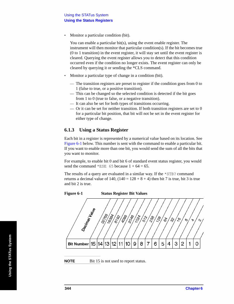
Using the STATus SystemUsing the Status Registers
Usi
ng th
e ST
ATus
Sys
tem
• Monitor a particular condition (bit).
You can enable a particular bit(s), using the event enable register. The instrument will then monitor that particular condition(s). If the bit becomes true (0 to 1 transition) in the event register, it will stay set until the event register is cleared. Querying the event register allows you to detect that this condition occurred even if the condition no longer exists. The event register can only be cleared by querying it or sending the *CLS command.
• Monitor a particular type of change in a condition (bit).
— The transition registers are preset to register if the condition goes from 0 to 1 (false to true, or a positive transition).
— This can be changed so the selected condition is detected if the bit goes from 1 to 0 (true to false, or a negative transition).
— It can also be set for both types of transitions occurring.— Or it can be set for neither transition. If both transition registers are set to 0
for a particular bit position, that bit will not be set in the event register for either type of change.
6.1.3 Using a Status Register
Each bit in a register is represented by a numerical value based on its location. See Figure 6-1 below. This number is sent with the command to enable a particular bit. If you want to enable more than one bit, you would send the sum of all the bits that you want to monitor.
For example, to enable bit 0 and bit 6 of standard event status register, you would send the command *ESE 65 because 1 + 64 = 65.
The results of a query are evaluated in a similar way. If the *STB? command returns a decimal value of 140, (140 = 128 + 8 + 4) then bit 7 is true, bit 3 is true and bit 2 is true.
Figure 6-1 Status Register Bit Values
NOTE Bit 15 is not used to report status.
344 Chapter 6
Using the STATus SystemUsing the Status Registers
Using the STATus System
6.1.4 Using the Service Request (SRQ) Method
Your language, bus and programming environment must be able to support SRQ interrupts. (For example, BASIC used with the GPIB.) SRQ is available on SICL LAN, USB, and GPIB.When you monitor a condition with the SRQ method, you must:
1. Determine which bit monitors the condition.
2. Determine how that bit reports to the request service (RQS) bit of the status byte.
3. Send GPIB commands to enable the bit that monitors the condition and to enable the summary bits that report the condition to the RQS bit.
4. Enable the controller to respond to service requests.
When the condition changes, the instrument sets its RQS bit and the GPIB SRQ line. The controller is informed of the change as soon as it occurs. As a result, the time the controller would otherwise have used to monitor the condition can be used to perform other tasks. Your program determines how the controller responds to the SRQ.
6.1.4.1 Generating a Service Request
To use the SRQ method, you must understand how service requests are generated. Bit 6 of the status byte register is the request service (RQS) bit. The *SRE command is used to configure the RQS bit to report changes in instrument status. When such a change occurs, the RQS bit is set. It is cleared when the status byte register is queried using *SRE? (with a serial poll.) It can be queried without erasing the contents with *STB?.
When a register set causes a summary bit in the status byte to change from 0 to 1, the instrument can initiate the service request (SRQ) process. However, the process is only initiated if both of the following conditions are true:
• The corresponding bit of the service request enable register is also set to 1.
• The instrument does not have a service request pending. (A service request is considered to be pending between the time the instrument’s SRQ process is initiated and the time the controller reads the status byte register.)
The SRQ process sets the GPIB SRQ line true. It also sets the status byte’s request service (RQS) bit to 1. Both actions are necessary to inform the controller that the instrument requires service. Setting the SRQ line only informs the controller that some device on the bus requires service. Setting the RQS bit allows the controller to determine which instrument requires service.
If your program enables the controller to detect and respond to service requests, it should instruct the controller to perform a serial poll when the GPIB SRQ line is set true. Each device on the bus returns the contents of its status byte register in response to this poll. The device whose RQS bit is set to 1 is the device that requested service.
Chapter 6 345

Using the STATus SystemUsing the Status Registers
Usi
ng th
e ST
ATus
Sys
tem
NOTE When you read the instrument’s status byte register with a serial poll, the RQS bit is reset to 0. Other bits in the register are not affected.
NOTE If the status register is configured to SRQ on end-of-measurement and the measurement is in continuous mode, then restarting a measurement (INIT command) can cause the measuring bit to pulse low. This causes an SRQ when you have not actually reached the "end-of-measurement" condition. To avoid this:
1. Set INITiate:CONTinuous off.
2. Set/enable the status registers.
3. Restart the measurement (send INIT).
346 Chapter 6
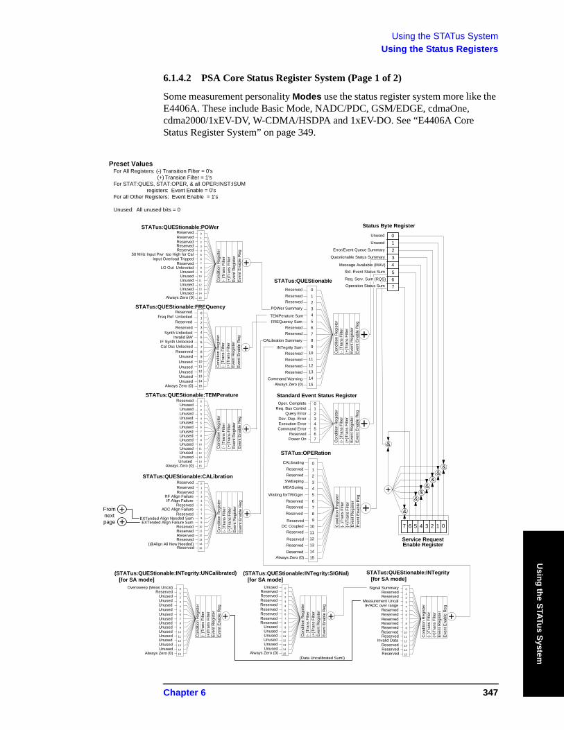
Using the STATus SystemUsing the Status Registers
Using the STATus System
6.1.4.2 PSA Core Status Register System (Page 1 of 2)
Some measurement personality Modes use the status register system more like the E4406A. These include Basic Mode, NADC/PDC, GSM/EDGE, cdmaOne, cdma2000/1xEV-DV, W-CDMA/HSDPA and 1xEV-DO. See “E4406A Core Status Register System” on page 349.
Standard Event Status Register
+
+
+
+STATus:QUEStionable
STATus:QUEStionable:POWer
STATus:QUEStionable:FREQuency
STATus:QUEStionable:TEMPerature
STATus:QUEStionable:CALibration
STATus:OPERation
ReservedReservedReservedReservedReserved
Synth Unlocked
Unused
IF Align FailureRF Align Failure
ReservedReserved
UnusedUnusedUnused
Reserved
Freq Ref UnlockedReservedReserved
Reserved
50 MHz Input Pwr too High for Cal
Invalid BW
Unused
Reserved
Input Overload Tripped
IF Synth Unlocked
Unused
ADC Align Failure
Reserved
Cal Osc Unlocked
Unused
Reserved
LO Out Unleveled
Reserved
Unused
EXTended Align Needed Sum
Unused
Unused
Unused
EXTended Align Failure Sum
Unused
Unused
Unused
Reserved
Unused
Unused
Unused
Reserved
Unused
Unused
Unused
Reserved
Unused
Unused
Unused
Reserved
Unused
Unused
Unused
(@Align All Now Needed)
Always Zero (0)
Always Zero (0)Always Zero (0)
Always Zero (0)
Always Zero (0)
Reserved
+
ReservedReservedReserved
Reserved
ReservedReservedReservedReserved
Command Warning
INTegrity Sum
TEMPerature Sum
POWer Summary
Reserved
CALibration Summary
FREQuency Sum
++
+
Reserved
SWEepingMEASuring
Waiting forTRIGger
CALibrating
Reserved
ReservedReservedReserved
Reserved
Reserved
DC CoupledReserved
ReservedReserved
Status Byte Register
Service RequestEnable Register
01234567
7
&
&&
&&
&&
6 5 4 3 2 1 0
Operation Status Sum
Req. Serv. Sum (RQS)
Std. Event Status Sum
Message Available (MAV)
Error/Event Queue Summary
Unused
Unused
Questionable Status Summary
+
0 1 2 3 4 5 6 7 8 9101112131415
0 1 2 3 4 5 6 7 8 9101112131415
0 1 2 3 4 5 6 7 8 9101112131415
0 1 2 3 4 5 6 7 8 9101112131415
0 1 2 3 4 5 6 7 8 9101112131415
0 1 2 3 4 5 6 7 8 9101112131415
0 1 2 3 4 5 6 7
Oper. CompleteReq. Bus Control
Query ErrorDev. Dep. ErrorExecution ErrorCommand Error
ReservedPower On
Con
ditio
n R
egis
ter
(- )T
rans
Filt
er
(+)T
rans
Filt
erE
vent
Reg
iste
rE
vent
Ena
ble
Reg
Con
ditio
n R
egis
ter
(- )T
rans
Filt
er
(+)T
rans
Filt
erE
vent
Reg
iste
rE
vent
Ena
ble
Reg
Con
ditio
n R
egis
ter
(- )T
rans
Filt
er
(+)T
rans
Filt
erE
vent
Reg
iste
rE
vent
Ena
ble
Reg
Con
ditio
n R
egis
ter
(- )T
rans
Filt
er
(+)T
rans
Filt
erE
vent
Reg
iste
rE
vent
Ena
ble
Reg
Con
ditio
n R
egis
ter
(- )T
rans
Filt
er
(+)T
rans
Filt
erE
vent
Reg
iste
rE
vent
Ena
ble
Reg
Con
ditio
n R
egis
ter
(- )T
rans
Filt
er
(+)T
rans
Filt
erE
vent
Reg
iste
rE
vent
Ena
ble
Reg
Con
ditio
n R
egis
ter
(- )T
rans
Filt
er
(+)T
rans
Filt
erE
vent
Reg
iste
rE
vent
Ena
ble
Reg
STATus:QUEStionable:INTegrity [for SA mode]
IF/ADC over rangeMeasurement Uncal
ReservedReserved
Signal Summary
ReservedReservedReservedReservedReservedReservedReserved
Invalid DataReservedReservedReserved
0 1 2 3 4 5 6 7 8 9101112131415
Con
ditio
n R
egis
ter
(- )T
rans
Filt
er
(+)T
rans
Filt
erEv
ent R
egis
ter
Even
t Ena
ble
Reg
+
(STATus:QUEStionable:INTegrity:UNCalibrated) [for SA mode]
UnusedUnusedUnused
ReservedOversweep (Meas Uncal)
UnusedUnusedUnusedUnusedUnusedUnusedUnusedUnusedUnusedUnused
Always Zero (0)
0 1 2 3 4 5 6 7 8 9101112131415
Con
ditio
n R
egis
ter
(- )T
rans
Filt
er
(+)T
rans
Filt
erE
vent
Reg
iste
rE
vent
Ena
ble
Reg
(STATus:QUEStionable:INTegrity:SIGNal) [for SA mode]
ReservedReservedReservedReserved
Unused
ReservedReservedReservedReserved
UnusedUnusedUnusedUnusedUnusedUnused
Always Zero (0)
0 1 2 3 4 5 6 7 8 9101112131415
Con
ditio
n R
egis
ter
(- )T
rans
Filt
er
(+)T
rans
Filt
erE
vent
Reg
iste
rE
vent
Ena
ble
Reg
+
(Data Uncalibrated Suml)
Preset Values For All Registers: (-) Transition Filter = 0's (+) Transion Filter = 1's For STAT:QUES, STAT:OPER, & all OPER:INST:ISUM registers: Event Enable = 0's For all Other Registers: Event Enable = 1's
Unused: All unused bits = 0
&
++From
next page
Reserved
Chapter 6 347

Using the STATus SystemUsing the Status Registers
Usi
ng th
e ST
ATus
Sys
tem
6.1.4.3 PSA Core Status Register System (Page 2 of 2)
(@#STATus:QUEStionable:CALibration:EXTended:FAILure)
Unused
(@Characterize YTF Failure)(#EMI Radiated Align Failure)
(#EMI Conducted Align Failure )
UnusedUnusedUnusedUnusedUnusedUnusedUnusedUnusedUnusedUnused
Always Zero (0)
0 1 2 3 4
5 6 7 8
91011
12131415
To bit 9 STATus:QUEStionable:CALibration
Con
ditio
n R
egis
ter
(- )T
rans
Filt
er
(+)T
rans
Filt
erE
vent
Reg
iste
rEv
ent E
nabl
e R
eg
+
Unused
Unused
(#@Align EMI Radiated Needed)(#@Align EMI Conducted Needed)
Unused
UnusedUnusedUnusedUnusedUnusedUnusedUnusedUnusedUnusedUnused
Always Zero (0)
0 1
2 3 4 5 6 7 8 91011
121314
15
Con
ditio
n R
egis
ter
(- )T
rans
Filt
er
(+)T
rans
Filt
erEv
ent R
egis
ter
Eve
nt E
nabl
e R
eg
Unused
(@#STATus:QUEStionable:CALibration:EXTended:NEEDed)
+To bit 14 STATus:QUEStionable:CALibration
348 Chapter 6
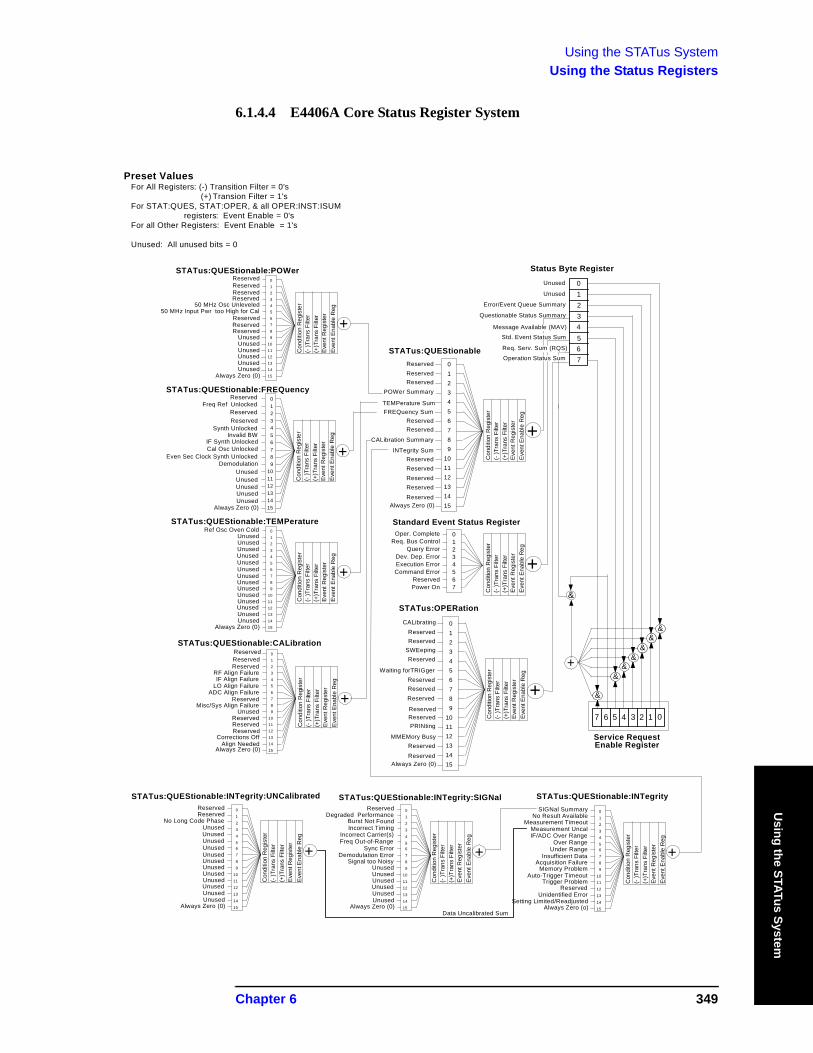
Using the STATus SystemUsing the Status Registers
Using the STATus System
6.1.4.4 E4406A Core Status Register System
Standard Event Status Register
+
+
+
+STATus:QUEStionable
STATus:QUEStionable:POWer
STATus:QUEStionable:FREQuency
STATus:QUEStionable:TEMPerature
STATus:QUEStionable:CALibration
STATus:OPERation
ReservedReservedReservedReserved
50 MHz Osc Unleveled
Synth Unlocked
Unused
IF Align FailureRF Align Failure
ReservedReservedReserved
UnusedUnusedUnused
Ref Osc Oven Cold
Freq Ref UnlockedReservedReserved
Reserved
50 MHz Input Pwr too High for Cal
Invalid BW
Unused
LO Align Failure
Reserved
IF Synth Unlocked
Unused
ADC Align Failure
Reserved
Cal Osc Unlocked
Unused
Reserved
Reserved
Even Sec Clock Synth Unlocked
Unused
Misc/Sys Align Failure
Unused
Demodulation
Unused
Unused
Unused
Unused
Unused
Reserved
Unused
Unused
Unused
Reserved
Unused
Unused
Unused
Reserved
Unused
Unused
Unused
Corrections Off
Unused
Unused
Unused
Align Needed
Always Zero (0)
Always Zero (0)Always Zero (0)
Always Zero (0)
Always Zero (0)
Always Zero (0)
+
ReservedReservedReserved
Reserved
ReservedReservedReservedReservedReserved
INTegrity Sum
TEMPerature Sum
POWer Summary
Reserved
CALibration Summary
FREQuency Sum
++
+
Reserved
SWEepingReserved
Waiting forTRIGger
CALibrating
Reserved
ReservedReservedReserved
Reserved
MMEMory Busy
ReservedPRINting
ReservedReserved
Status Byte Register
Service RequestEnable Register
01234567
7
&
&&
&&
&&
6 5 4 3 2 1 0
Operation Status Sum
Req. Serv. Sum (RQS)
Std. Event Status Sum
Message Available (MAV)
Error/Event Queue Summary
Unused
Unused
Questionable Status Summary
+
0 1 2 3 4 5 6 7 8 9101112131415
0 1 2 3 4 5 6 7 8 9101112131415
0 1 2 3 4 5 6 7 8 9101112131415
0 1 2 3 4 5 6 7 8 9101112131415
0 1 2 3 4 5 6 7 8 9101112131415
0 1 2 3 4 5 6 7 8 9101112131415
0 1 2 3 4 5 6 7
Oper. CompleteReq. Bus Control
Query ErrorDev. Dep. ErrorExecution ErrorCommand Error
ReservedPower On
Con
ditio
n R
egis
ter
(- )T
rans
Filt
er
(+)T
rans
Filt
erE
vent
Reg
iste
rE
vent
Ena
ble
Reg
Con
ditio
n R
egis
ter
(- )T
rans
Filt
er
(+)T
rans
Filt
erE
vent
Reg
iste
rE
vent
Ena
ble
Reg
Con
ditio
n R
egis
ter
(- )T
rans
Filt
er
(+)T
rans
Filt
erE
vent
Reg
iste
rE
vent
Ena
ble
Reg
Con
ditio
n R
egis
ter
(- )T
rans
Filt
er
(+)T
rans
Filt
erE
vent
Reg
iste
rE
vent
Ena
ble
Reg
Con
ditio
n R
egis
ter
(- )T
rans
Filt
er
(+)T
rans
Filt
erE
vent
Reg
iste
rE
vent
Ena
ble
Reg
Con
ditio
n R
egis
ter
(- )T
rans
Filt
er
(+)T
rans
Filt
erE
vent
Reg
iste
rE
vent
Ena
ble
Reg
Con
ditio
n R
egis
ter
(- )T
rans
Filt
er
(+)T
rans
Filt
erE
vent
Reg
iste
rE
vent
Ena
ble
Reg
STATus:QUEStionable:INTegrity
IF/ADC Over RangeMeasurement Uncal
Measurement TimeoutNo Result Available
SIGNal Summary
Over RangeUnder Range
Insufficient DataAcquisition Failure
Memory ProblemAuto-Trigger Timeout
Trigger ProblemReserved
Unidentified ErrorSetting Limited/Readjusted
Always Zero (o)
0
1 2 3 4
5 6 7
8 91011
1213
14
15
Con
ditio
n R
egis
ter
(- )T
rans
Filt
er
(+)T
rans
Filt
erE
vent
Reg
iste
rE
vent
Ena
ble
Reg
STATus:QUEStionable:INTegrity:SIGNal
Incorrect Carrier(s)Incorrect TimingBurst Not Found
Degraded PerformanceReserved
Freq Out-of-RangeSync Error
Demodulation ErrorSignal too Noisy
UnusedUnusedUnusedUnusedUnusedUnused
Always Zero (0)
0 1 2 3
4
5 6 7 8
9101112
13
1415
Con
ditio
n R
egis
ter
(- )T
rans
Filt
er
(+)T
rans
Filt
erE
vent
Reg
iste
rE
vent
Ena
ble
Reg
+
Preset Values For All Registers: (-) Transition Filter = 0's (+) Transion Filter = 1's For STAT:QUES, STAT:OPER, & all OPER:INST:ISUM registers: Event Enable = 0's For all Other Registers: Event Enable = 1's
Unused: All unused bits = 0
+
STATus:QUEStionable:INTegrity:UNCalibrated
UnusedUnused
No Long Code PhaseReservedReserved
UnusedUnusedUnusedUnusedUnusedUnusedUnusedUnusedUnusedUnused
Always Zero (0)
0
1 2 3 4 5 6 7
8 9
1011
1213
14
15
Con
ditio
n R
egis
ter
(- )T
rans
Filt
er
(+)T
rans
Filt
erE
vent
Reg
iste
rE
vent
Ena
ble
Reg
Data Uncalibrated Sum
&
Chapter 6 349
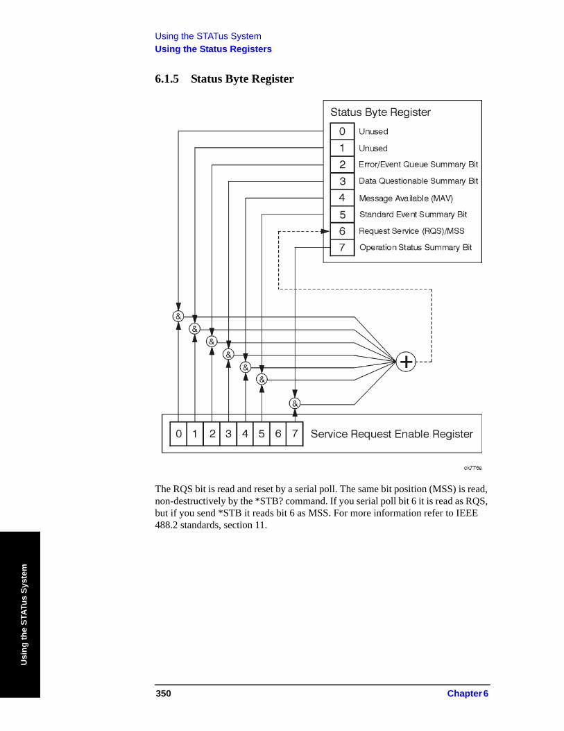
Using the STATus SystemUsing the Status Registers
Usi
ng th
e ST
ATus
Sys
tem
6.1.5 Status Byte Register
The RQS bit is read and reset by a serial poll. The same bit position (MSS) is read, non-destructively by the *STB? command. If you serial poll bit 6 it is read as RQS, but if you send *STB it reads bit 6 as MSS. For more information refer to IEEE 488.2 standards, section 11.
350 Chapter 6
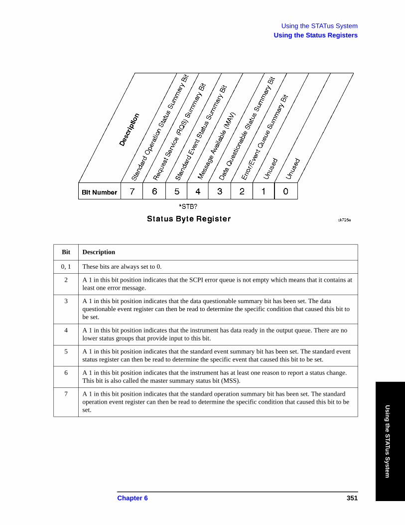
Using the STATus SystemUsing the Status Registers
Using the STATus System
Bit Description
0, 1 These bits are always set to 0.
2 A 1 in this bit position indicates that the SCPI error queue is not empty which means that it contains at least one error message.
3 A 1 in this bit position indicates that the data questionable summary bit has been set. The data questionable event register can then be read to determine the specific condition that caused this bit to be set.
4 A 1 in this bit position indicates that the instrument has data ready in the output queue. There are no lower status groups that provide input to this bit.
5 A 1 in this bit position indicates that the standard event summary bit has been set. The standard event status register can then be read to determine the specific event that caused this bit to be set.
6 A 1 in this bit position indicates that the instrument has at least one reason to report a status change. This bit is also called the master summary status bit (MSS).
7 A 1 in this bit position indicates that the standard operation summary bit has been set. The standard operation event register can then be read to determine the specific condition that caused this bit to be set.
Chapter 6 351
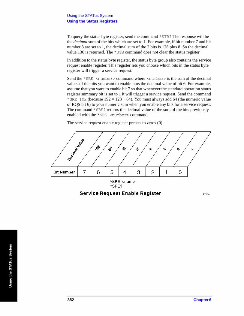
Using the STATus SystemUsing the Status Registers
Usi
ng th
e ST
ATus
Sys
tem
To query the status byte register, send the command *STB? The response will be the decimal sum of the bits which are set to 1. For example, if bit number 7 and bit number 3 are set to 1, the decimal sum of the 2 bits is 128 plus 8. So the decimal value 136 is returned. The *STB command does not clear the status register
In addition to the status byte register, the status byte group also contains the service request enable register. This register lets you choose which bits in the status byte register will trigger a service request.
Send the *SRE <number> command where <number> is the sum of the decimal values of the bits you want to enable plus the decimal value of bit 6. For example, assume that you want to enable bit 7 so that whenever the standard operation status register summary bit is set to 1 it will trigger a service request. Send the command *SRE 192 (because 192 = 128 + 64). You must always add 64 (the numeric value of RQS bit 6) to your numeric sum when you enable any bits for a service request. The command *SRE? returns the decimal value of the sum of the bits previously enabled with the *SRE <number> command.
The service request enable register presets to zeros (0).
352 Chapter 6
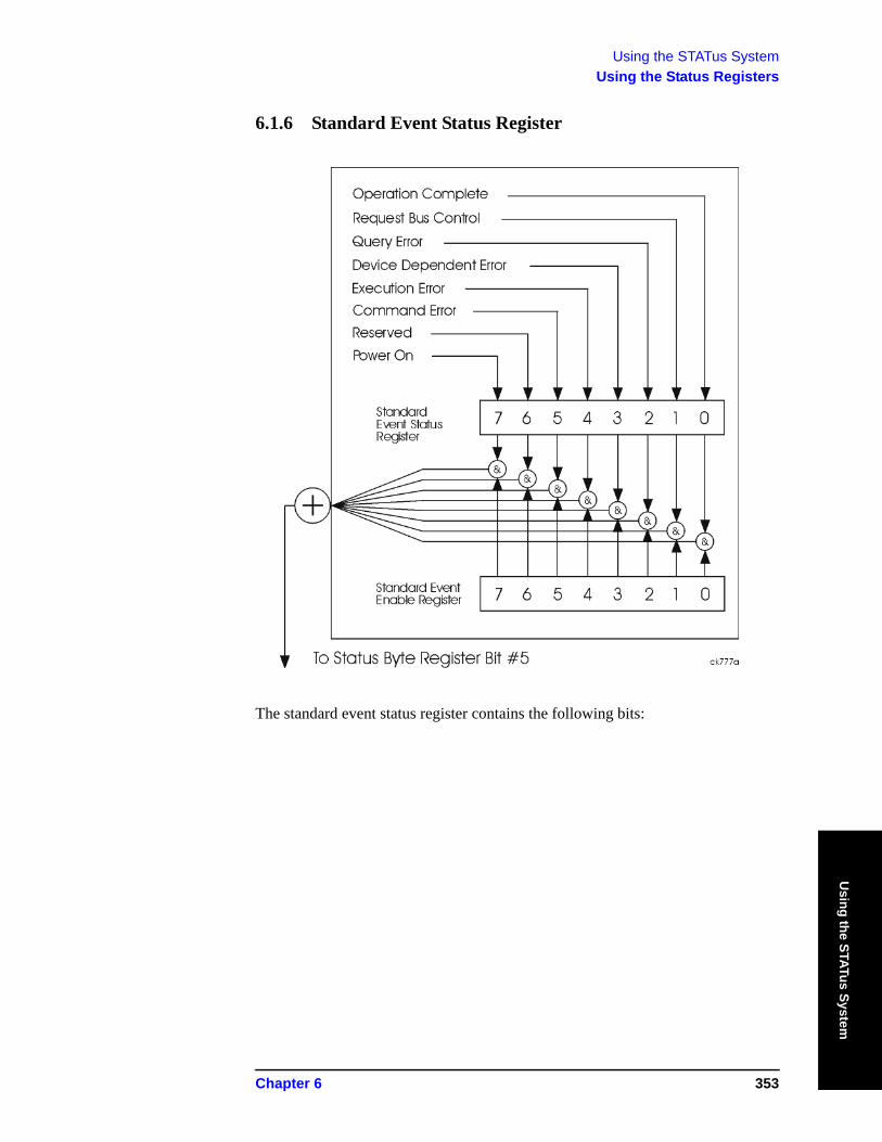
Using the STATus SystemUsing the Status Registers
Using the STATus System
6.1.6 Standard Event Status Register
The standard event status register contains the following bits:
Chapter 6 353
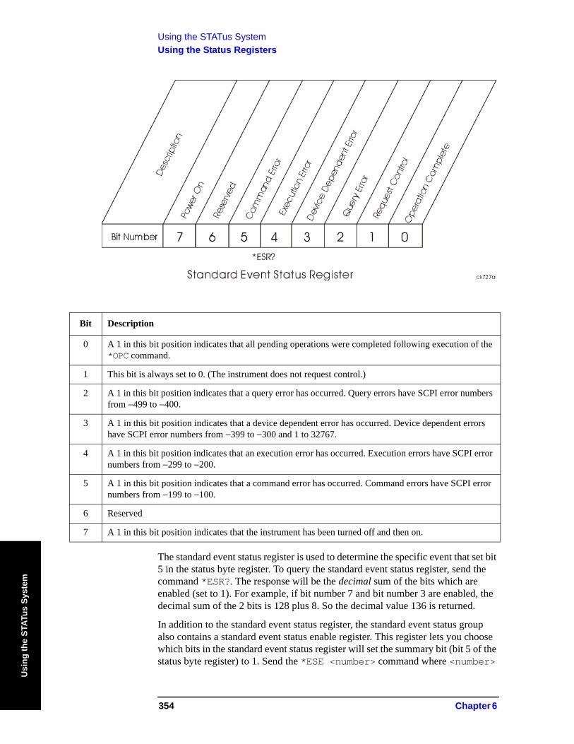
Using the STATus SystemUsing the Status Registers
Usi
ng th
e ST
ATus
Sys
tem
The standard event status register is used to determine the specific event that set bit 5 in the status byte register. To query the standard event status register, send the command *ESR?. The response will be the decimal sum of the bits which are enabled (set to 1). For example, if bit number 7 and bit number 3 are enabled, the decimal sum of the 2 bits is 128 plus 8. So the decimal value 136 is returned.
In addition to the standard event status register, the standard event status group also contains a standard event status enable register. This register lets you choose which bits in the standard event status register will set the summary bit (bit 5 of the status byte register) to 1. Send the *ESE <number> command where <number>
Bit Description
0 A 1 in this bit position indicates that all pending operations were completed following execution of the *OPC command.
1 This bit is always set to 0. (The instrument does not request control.)
2 A 1 in this bit position indicates that a query error has occurred. Query errors have SCPI error numbers from −499 to −400.
3 A 1 in this bit position indicates that a device dependent error has occurred. Device dependent errors have SCPI error numbers from −399 to −300 and 1 to 32767.
4 A 1 in this bit position indicates that an execution error has occurred. Execution errors have SCPI error numbers from −299 to −200.
5 A 1 in this bit position indicates that a command error has occurred. Command errors have SCPI error numbers from −199 to −100.
6 Reserved
7 A 1 in this bit position indicates that the instrument has been turned off and then on.
354 Chapter 6
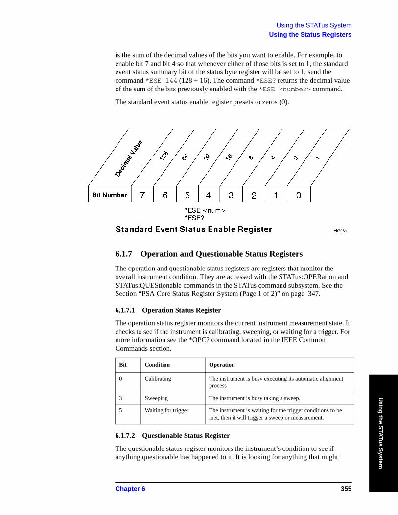
Using the STATus SystemUsing the Status Registers
Using the STATus System
is the sum of the decimal values of the bits you want to enable. For example, to enable bit 7 and bit 4 so that whenever either of those bits is set to 1, the standard event status summary bit of the status byte register will be set to 1, send the command *ESE 144 (128 + 16). The command *ESE? returns the decimal value of the sum of the bits previously enabled with the *ESE <number> command.
The standard event status enable register presets to zeros (0).
6.1.7 Operation and Questionable Status Registers
The operation and questionable status registers are registers that monitor the overall instrument condition. They are accessed with the STATus:OPERation and STATus:QUEStionable commands in the STATus command subsystem. See the Section “PSA Core Status Register System (Page 1 of 2)” on page 347.
6.1.7.1 Operation Status Register
The operation status register monitors the current instrument measurement state. It checks to see if the instrument is calibrating, sweeping, or waiting for a trigger. For more information see the *OPC? command located in the IEEE Common Commands section.
6.1.7.2 Questionable Status Register
The questionable status register monitors the instrument’s condition to see if anything questionable has happened to it. It is looking for anything that might
Bit Condition Operation
0 Calibrating The instrument is busy executing its automatic alignment process
3 Sweeping The instrument is busy taking a sweep.
5 Waiting for trigger The instrument is waiting for the trigger conditions to be met, then it will trigger a sweep or measurement.
Chapter 6 355
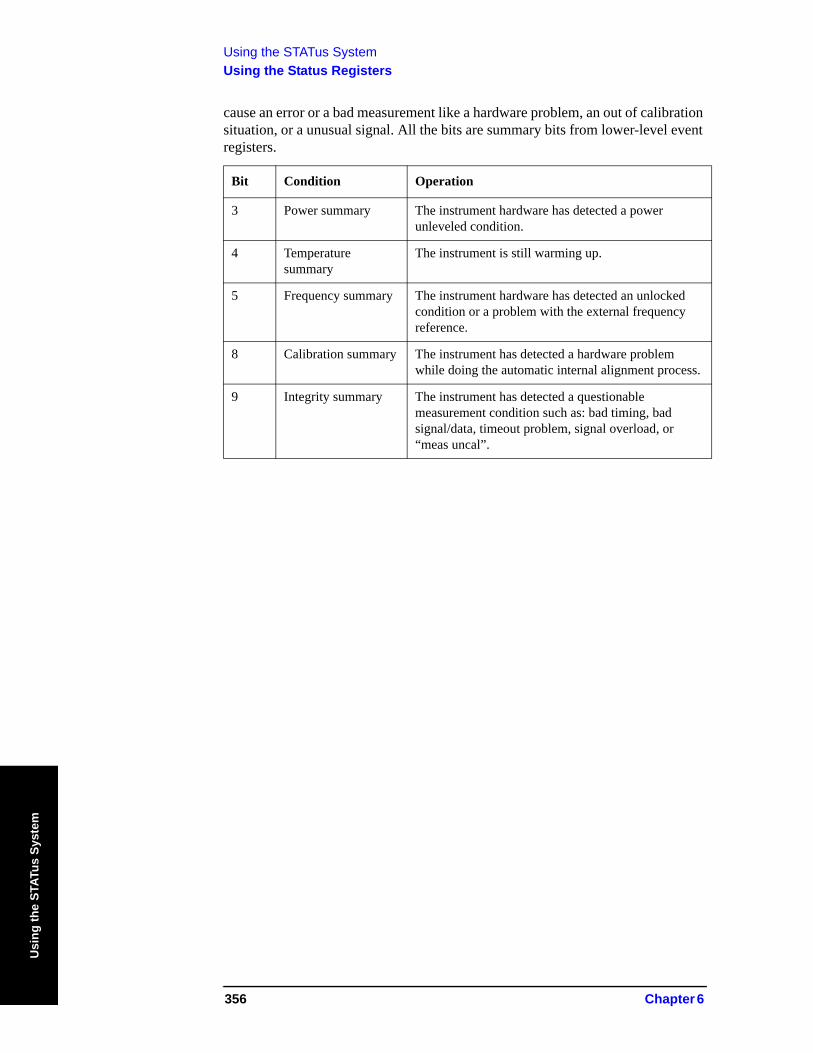
Using the STATus SystemUsing the Status Registers
Usi
ng th
e ST
ATus
Sys
tem
cause an error or a bad measurement like a hardware problem, an out of calibration situation, or a unusual signal. All the bits are summary bits from lower-level event registers.
Bit Condition Operation
3 Power summary The instrument hardware has detected a power unleveled condition.
4 Temperature summary
The instrument is still warming up.
5 Frequency summary The instrument hardware has detected an unlocked condition or a problem with the external frequency reference.
8 Calibration summary The instrument has detected a hardware problem while doing the automatic internal alignment process.
9 Integrity summary The instrument has detected a questionable measurement condition such as: bad timing, bad signal/data, timeout problem, signal overload, or “meas uncal”.
356 Chapter 6
Using the STATus SystemUsing the STATus System IEEE Commands
Using the STATus System
6.2 Using the STATus System IEEE CommandsThese commands are specified in IEEE Standard 488.2-1992, IEEE Standard Codes, Formats, Protocols and Common Commands for Use with ANSI/IEEE Std 488.1-1987. New York, NY, 1992.
Numeric values for bit patterns can be entered using decimal or hexadecimal representations. (that is, 0 to 32767 is equivalent to #H0 to #H7FFF) See the SCPI Basics information about using bit patterns for variable parameters.
6.2.1 Calibration Query
*CAL?
Performs a full alignment and returns a number indicating the success of the alignment. A zero is returned if the alignment is successful. A one is returned if any part of the alignment fails. The equivalent SCPI command is CALibrate[:ALL]?
Front Panel Access: System, Alignments, Align All Now
6.2.2 Clear Status
*CLS
Clears the status byte. It does this by emptying the error queue and clearing all bits in all of the event registers. The status byte registers summarize the states of the other registers. It is also responsible for generating service requests.
Key Type: There is no equivalent front-panel key.
6.2.3 Standard Event Status Enable
*ESE <number>
*ESE?
Selects the desired bits from the standard event status enable register. This register monitors I/O errors and synchronization conditions such as operation complete, request control, query error, device dependent error, execution error, command error and power on. The selected bits are ORed to become a summary bit (bit 5) in the status byte register which can be queried.
The query returns the state of the standard event status enable register.
Key Type: There is no equivalent front-panel key.
Range: Integer, 0 to 255
Chapter 6 357
Using the STATus SystemUsing the STATus System IEEE Commands
Usi
ng th
e ST
ATus
Sys
tem
6.2.4 Standard Event Status Register Query
*ESR?
Queries and clears the standard event status event register. (This is a destructive read.)
Key Type: There is no equivalent front-panel key.
Range: Integer, 0 to 255
6.2.5 Identification Query
*IDN?
Returns an instrument identification information. The string will contain the model number, serial number and firmware revision.
The response is organized into four fields separated by commas. The field definitions are as follows:
• Manufacturer
• Model
• Serial number
• Firmware version
For example:
Agilent Technologies,E4440A,US00000123,B.02.02
Key Type: There is no equivalent front-panel key.
Remarks: An @ in the firmware revision information indicates that it is prototype firmware.
Front Panel Access: System, Show System
358 Chapter 6
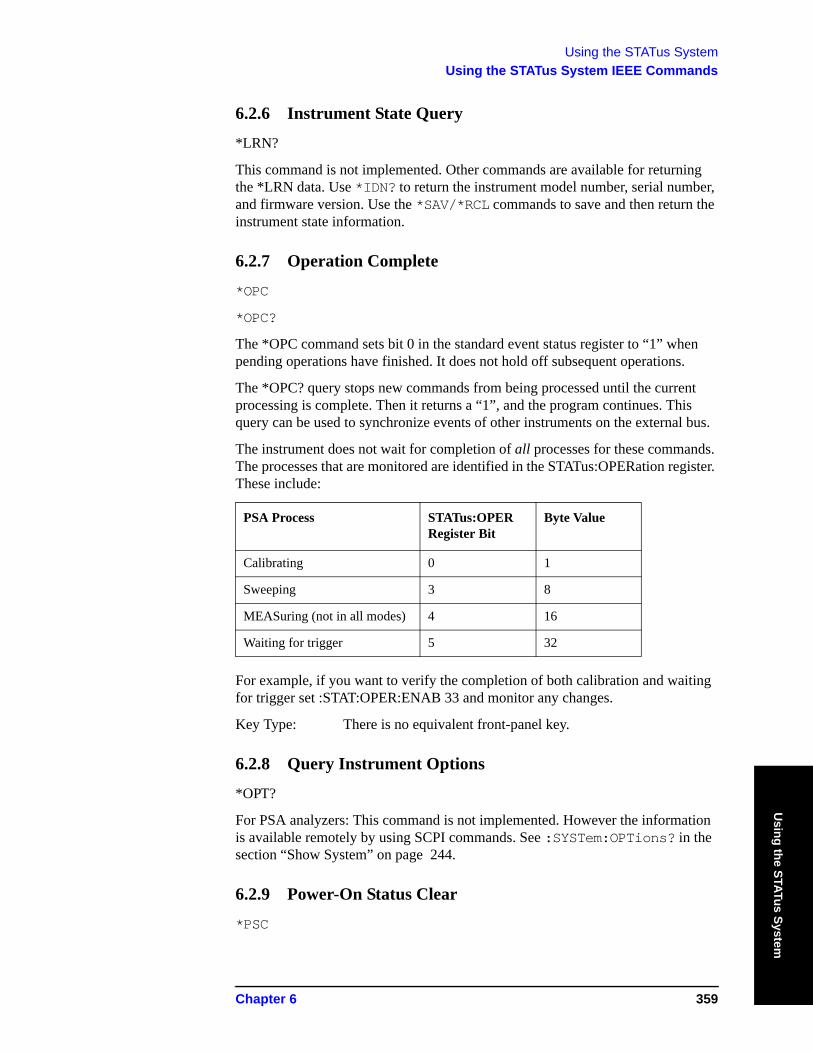
Using the STATus SystemUsing the STATus System IEEE Commands
Using the STATus System
6.2.6 Instrument State Query
*LRN?
This command is not implemented. Other commands are available for returning the *LRN data. Use *IDN? to return the instrument model number, serial number, and firmware version. Use the *SAV/*RCL commands to save and then return the instrument state information.
6.2.7 Operation Complete
*OPC
*OPC?
The *OPC command sets bit 0 in the standard event status register to “1” when pending operations have finished. It does not hold off subsequent operations.
The *OPC? query stops new commands from being processed until the current processing is complete. Then it returns a “1”, and the program continues. This query can be used to synchronize events of other instruments on the external bus.
The instrument does not wait for completion of all processes for these commands. The processes that are monitored are identified in the STATus:OPERation register. These include:
For example, if you want to verify the completion of both calibration and waiting for trigger set :STAT:OPER:ENAB 33 and monitor any changes.
Key Type: There is no equivalent front-panel key.
6.2.8 Query Instrument Options
*OPT?
For PSA analyzers: This command is not implemented. However the information is available remotely by using SCPI commands. See :SYSTem:OPTions? in the section “Show System” on page 244.
6.2.9 Power-On Status Clear
*PSC
PSA Process STATus:OPER Register Bit
Byte Value
Calibrating 0 1
Sweeping 3 8
MEASuring (not in all modes) 4 16
Waiting for trigger 5 32
Chapter 6 359
Using the STATus SystemUsing the STATus System IEEE Commands
Usi
ng th
e ST
ATus
Sys
tem
*PSC?
Sets the state of the power-on status clear flag. This command allows you to specify if the service request enable register and the event status enable register should be cleared at power up.
The query returns the contents of the power-on status clear flag.
Key Type: There is no equivalent front-panel key.
6.2.10 Recall
*RCL <register>
This command recalls the instrument state from the specified instrument memory register.
If the state being loaded has a newer firmware revision than the revision of the instrument, no state is recalled and an error is reported.
If the state being loaded has an equal firmware revision than the revision of the instrument, the state will be loaded.
If the state being loaded has an older firmware revision than the revision of the instrument, the instrument will only load the parts of the state that apply to the older revision.
Key Type: There is no equivalent front-panel key.
Range: Registers are an integer, 0 to 127
Remarks: See also commands :MMEMory:LOAD:STATe and :MMEMory:STORe:STATe
Example: *RCL 12
Front Panel Access: File, Recall State
6.2.11 Reset
*RST
This command presets the instrument to a factory defined condition that is appropriate for remote programming operation. In Spectrum Analysis Mode *RST is equivalent to performing the commands
• :SYSTem:PRESet, with preset type set to MODE.
• *CLS which clears the STATus bits and error queue
*RST does not change the mode and only resets the parameters for the current mode.
The :SYSTem:PRESet command is equivalent to a front panel Preset key.
360 Chapter 6
Using the STATus SystemUsing the STATus System IEEE Commands
Using the STATus System
6.2.12 Save
*SAV <register>
This command saves the instrument state to the specified instrument memory register.
Key Type: There is no equivalent front-panel key.
Range: Registers are an integer, 0 to 127
Remarks: See also commands :MMEMory:LOAD:STATe and :MMEMory:STORe:STATe
Example: *SAV 12
Front Panel Access: File, Save State
6.2.13 Service Request Enable
*SRE <integer>
*SRE?
This command sets the value of the service request enable register.
The query returns the value of the register.
Key Type: There is no equivalent front-panel key.
Range: Integer, 0 to 255
Example: *SRE 22
6.2.14 Read Status Byte Query
*STB?
Returns the value of the status byte register without erasing its contents.
Key Type: There is no equivalent front-panel key.
Remarks: See *CLS
Chapter 6 361
Using the STATus SystemUsing the STATus System IEEE Commands
Usi
ng th
e ST
ATus
Sys
tem
6.2.15 Trigger
*TRG
This command triggers the instrument. Use the :TRIGger[:SEQuence]:SOURce command to select the trigger source.
If you have selected a one-button measurement and it has been paused (INITiate:PAUSe), or the CONFigure:<meas> command was used, this command causes the system to exit this “waiting” state and go to the “initiated” state. The trigger system is initiated and completes one full trigger cycle. It returns to the “waiting” state on completion of the trigger cycle. See the MEASURE key for more information about controlling the measurement process.
The instrument must be in the single measurement mode. If INIT:CONT ON, then the command is ignored. Depending upon the measurement and the number of averages, there may be multiple data acquisitions, with multiple trigger events, for one full trigger cycle.
Key Type: There is no equivalent front-panel key.
Remarks: See also the :INITiate:IMMediate command
Front Panel Access: Restart
6.2.16 Self Test Query
*TST?
For PSA analyzers, NO tests are performed. *TST? always returns 0.
Key Type: There is no equivalent front-panel key.
6.2.17 Wait-to-Continue
*WAI
This command causes the instrument to wait until all pending commands/processes are completed before executing any additional commands. There is no query form for the command.
The instrument does not wait for completion of all processes. The processes that are monitored are identified in the *OPC? command description.
Key Type: There is no equivalent front-panel key.
Example: INIT:CONT OFF; INIT;*WAI
362 Chapter 6
Using the STATus SystemSTATus Subsystem
Using the STATus System
6.3 STATus SubsystemThe STATus subsystem controls the SCPI-defined instrument-status reporting structures. Each status register has a set of five commands used for querying or masking that particular register.
Numeric values for bit patterns can be entered using decimal or hexadecimal representations. (that is, 0 to 32767 is equivalent to #H0 to #H7FFF) See “Variable Parameters” on page 283 for information about using bit patterns for variable parameters.
6.3.1 Operation Register
6.3.1.1 Operation Condition Query
:STATus:OPERation:CONDition?
This query returns the decimal value of the sum of the bits in the Status Operation Condition register.
NOTE The data in this register is continuously updated and reflects the current conditions.
Key Type: There is no equivalent front-panel key.
6.3.1.2 Operation Enable
:STATus:OPERation:ENABle <integer>
:STATus:OPERation:ENABle?
This command determines which bits in the Operation Event register will set the Operation Status Summary bit (bit 7) in the Status Byte Register. The variable <number> is the sum of the decimal values of the bits you want to enable.
NOTE The preset condition is to have all bits in this enable register set to 0. To have any Operation Events reported to the Status Byte Register, one or more bits need to be set to 1.
Key Type: There is no equivalent front-panel key.
Factory Preset: 0
Range: 0 to 32767
Chapter 6 363
Using the STATus SystemSTATus Subsystem
Usi
ng th
e ST
ATus
Sys
tem
6.3.1.3 Operation Event Query
:STATus:OPERation[:EVENt]?
This query returns the decimal value of the sum of the bits in the Operation Event register.
NOTE The register requires that the associated PTR or NTR filters be set before a condition register bit can set a bit in the event register.
The data in this register is latched until it is queried. Once queried, the register is cleared.
Key Type: There is no equivalent front-panel key.
6.3.1.4 Operation Negative Transition
:STATus:OPERation:NTRansition <integer>
:STATus:OPERation:NTRansition?
This command determines which bits in the Operation Condition register will set the corresponding bit in the Operation Event register when the condition register bit has a negative transition (1 to 0). The variable <number> is the sum of the decimal values of the bits that you want to enable.
Key Type: There is no equivalent front-panel key.
Factory Preset: 0
Range: 0 to 32767
6.3.1.5 Operation Positive Transition
:STATus:OPERation:PTRansition <integer>
:STATus:OPERation:PTRansition?
This command determines which bits in the Operation Condition register will set the corresponding bit in the Operation Event register when the condition register bit has a positive transition (0 to 1). The variable <number> is the sum of the decimal values of the bits that you want to enable.
Key Type: There is no equivalent front-panel key.
Factory Preset: 32767 (all 1’s)
Range: 0 to 32767
6.3.2 Preset the Status Byte
:STATus:PRESet
Sets bits in most of the enable and transition registers to their default state. It presets all the Transition Filters, Enable Registers, and the Error/Event Queue Enable. It has no effect on Event Registers, Error/Event QUEue, IEEE 488.2 ESE,
364 Chapter 6
Using the STATus SystemSTATus Subsystem
Using the STATus System
and SRE Registers as described in IEEE Standard 488.2-1992, IEEE Standard Codes, Formats, Protocols and Common Commands for Use with ANSI/IEEE Std 488.1-1987. New York, NY, 1992.
Key Type: There is no equivalent front-panel key.
6.3.3 Questionable Register
6.3.3.1 Questionable Condition
:STATus:QUEStionable:CONDition?
This query returns the decimal value of the sum of the bits in the Questionable Condition register.
NOTE The data in this register is continuously updated and reflects the current conditions.
Key Type: There is no equivalent front-panel key.
6.3.3.2 Questionable Enable
:STATus:QUEStionable:ENABle <number>
:STATus:QUEStionable:ENABle?
This command determines which bits in the Questionable Event register will set the Questionable Status Summary bit (bit3) in the Status Byte Register. The variable <number> is the sum of the decimal values of the bits you want to enable.
NOTE The preset condition is all bits in this enable register set to 0. To have any Questionable Events reported to the Status Byte Register, one or more bits need to be set to 1. The Status Byte Event Register should be queried after each measurement to check the Questionable Status Summary (bit 3). If it is equal to 1, a condition during the test may have made the test results invalid. If it is equal to 0, this indicates that no hardware problem or measurement problem was detected by the analyzer.
Key Type: There is no equivalent front-panel key.
Factory Preset: 0
Range: 0 to 32767
6.3.3.3 Questionable Event Query
:STATus:QUEStionable[:EVENt]?
This query returns the decimal value of the sum of the bits in the Questionable Event register.
NOTE The register requires that the associated PTR or NTR filters be set
Chapter 6 365
Using the STATus SystemSTATus Subsystem
Usi
ng th
e ST
ATus
Sys
tem
before a condition register bit can set a bit in the event register.
The data in this register is latched until it is queried. Once queried, the register is cleared.
Key Type: There is no equivalent front-panel key.
6.3.3.4 Questionable Negative Transition
:STATus:QUEStionable:NTRansition <number>
:STATus:QUEStionable:NTRansition?
This command determines which bits in the Questionable Condition register will set the corresponding bit in the Questionable Event register when the condition register bit has a negative transition (1 to 0). The variable <number> is the sum of the decimal values of the bits that you want to enable.
Key Type: There is no equivalent front-panel key.
Factory Preset: 0
Range: 0 to 32767
6.3.3.5 Questionable Positive Transition
:STATus:QUEStionable:PTRansition <number>
:STATus:QUEStionable:PTRansition?
This command determines which bits in the Questionable Condition register will set the corresponding bit in the Questionable Event register when the condition register bit has a positive transition (0 to 1). The variable <number> is the sum of the decimal values of the bits that you want to enable.
Key Type: There is no equivalent front-panel key.
Factory Preset: 32767 (all 1’s)
Range: 0 to 32767
6.3.4 Questionable Calibration Register
6.3.4.1 Questionable Calibration Condition
:STATus:QUEStionable:CALibration:CONDition?
This query returns the decimal value of the sum of the bits in the Questionable Calibration Condition register.
NOTE The data in this register is continuously updated and reflects the
366 Chapter 6
Using the STATus SystemSTATus Subsystem
Using the STATus System
current conditions.
Key Type: There is no equivalent front-panel key.
6.3.4.2 Questionable Calibration Enable
:STATus:QUEStionable:CALibration:ENABle <number>
:STATus:QUEStionable:CALibration:ENABle?
This command determines which bits in the Questionable Calibration Condition Register will set bits in the Questionable Calibration Event register, which also sets the Calibration Summary bit (bit 8) in the Questionable Register. The variable <number> is the sum of the decimal values of the bits you want to enable.
Key Type: There is no equivalent front-panel key.
Example STAT:QUES:CAL:ENABLE 16384 could be used if you have turned off the automatic alignment and you want to query whether an alignment is needed.
Factory Preset: 32767 (all 1’s)
Range: 0 to 32767
6.3.4.3 Questionable Calibration Event Query
:STATus:QUEStionable:CALibration[:EVENt]?
This query returns the decimal value of the sum of the bits in the Questionable Calibration Event register.
NOTE The register requires that the associated PTR or NTR filters be set before a condition register bit can set a bit in the event register.
The data in this register is latched until it is queried. Once queried, the register is cleared.
Key Type: There is no equivalent front-panel key.
6.3.4.4 Questionable Calibration Negative Transition
:STATus:QUEStionable:CALibration:NTRansition <number>
:STATus:QUEStionable:CALibration:NTRansition?
This command determines which bits in the Questionable Calibration Condition register will set the corresponding bit in the Questionable Calibration Event register when the condition register bit has a negative transition (1 to 0). The variable <number> is the sum of the decimal values of the bits that you want to enable.
Chapter 6 367
Using the STATus SystemSTATus Subsystem
Usi
ng th
e ST
ATus
Sys
tem
Key Type: There is no equivalent front-panel key.
Factory Preset: 0
Range: 0 to 32767
6.3.4.5 Questionable Calibration Positive Transition
:STATus:QUEStionable:CALibration:PTRansition <number>
:STATus:QUEStionable:CALibration:PTRansition?
This command determines which bits in the Questionable Calibration Condition register will set the corresponding bit in the Questionable Calibration Event register when the condition register bit has a positive transition (0 to 1). The variable <number> is the sum of the decimal values of the bits that you want to enable.
Key Type: There is no equivalent front-panel key.
Factory Preset: 32767 (all 1’s)
Range: 0 to 32767
6.3.5 Questionable Calibration Extended Needed Register
6.3.5.1 Questionable Calibration Extended Needed Condition
:STATus:QUEStionable:CALibration:EXTended:NEEDed:CONDition?
This query returns the decimal value of the sum of the bits in the Questionable Calibration Extended Needed Condition register.
NOTE The data in this register is continuously updated and reflects the current conditions.
Key Type: There is no equivalent front-panel key.
6.3.5.2 Questionable Calibration Extended Needed Enable
:STATus:QUEStionable:CALibration:EXTended:NEEDed:ENABle <number>
:STATus:QUEStionable:CALibration:EXTended:NEEDed:ENABle?
This command determines which bits in the Questionable Calibration Extended Needed Enable Register will set bits in the Questionable Calibration Event register, which also sets the Calibration Summary bit (bit 8) in the Questionable Register. The variable <number> is the sum of the decimal values of the bits you want to enable.
368 Chapter 6
Using the STATus SystemSTATus Subsystem
Using the STATus System
Key Type: There is no equivalent front-panel key.
Example STAT:QUES:CAL:EXT:NEED:ENABLE 16384 could be used if you have turned off the automatic alignment and you want to query whether an alignment is needed.
Factory Preset: 32767 (all 1’s)
Range: 0 to 32767
6.3.5.3 Questionable Calibration Extended Needed Event Query
:STATus:QUEStionable:CALibration:EXTended:NEEDed[:EVENt]?
This query returns the decimal value of the sum of the bits in the Questionable Calibration Extended Needed Event register.
NOTE The register requires that the associated PTR or NTR filters be set before a condition register bit can set a bit in the event register.
The data in this register is latched until it is queried. Once queried, the register is cleared.
Key Type: There is no equivalent front-panel key.
6.3.5.4 Questionable Calibration Extended Needed Negative Transition
:STATus:QUEStionable:CALibration:EXTended:NEEDed: NTRansition <number>
:STATus:QUEStionable:CALibration:EXTended:NEEDed: NTRansition?
This command determines which bits in the Questionable Calibration Extended Needed Negative Transition register will set the corresponding bit in the Questionable Calibration Event register when the condition register bit has a negative transition (1 to 0). The variable <number> is the sum of the decimal values of the bits that you want to enable.
Key Type: There is no equivalent front-panel key.
Factory Preset: 0
Range: 0 to 32767
6.3.5.5 Questionable Calibration Extended Needed Positive Transition
:STATus:QUEStionable:CALibration:EXTended:NEEDed: PTRansition <number>
:STATus:QUEStionable:CALibration:EXTended:NEEDed: PTRansition?
This command determines which bits in the Questionable Calibration Extended Needed Positive Transition register will set the corresponding bit in the Questionable Calibration Event register when the condition register bit has a
Chapter 6 369
Using the STATus SystemSTATus Subsystem
Usi
ng th
e ST
ATus
Sys
tem
positive transition (0 to 1). The variable <number> is the sum of the decimal values of the bits that you want to enable.
Key Type: There is no equivalent front-panel key.
Factory Preset: 32767 (all 1’s)
Range: 0 to 32767
6.3.6 Questionable Calibration Extended Failure Register
6.3.6.1 Questionable Calibration Extended Failure Condition
:STATus:QUEStionable:CALibration:EXTended:FAILure: CONDition?
This query returns the decimal value of the sum of the bits in the Questionable Calibration Extended Failure Condition register.
NOTE The data in this register is continuously updated and reflects the current conditions.
Key Type: There is no equivalent front-panel key.
6.3.6.2 Questionable Calibration Extended Failure Enable
:STATus:QUEStionable:CALibration:EXTended:FAILure:ENABle <number>
:STATus:QUEStionable:CALibration:EXTended:FAILure:ENABle?
This command determines which bits in the Questionable Calibration Extended Failure Enable Register will set bits in the Questionable Calibration Event register, which also sets the Calibration Summary bit (bit 8) in the Questionable Register. The variable <number> is the sum of the decimal values of the bits you want to enable.
Key Type: There is no equivalent front-panel key.
Example STAT:QUES:CAL:EXT:FAIL:ENABLE 16384 could be used if you have turned off the automatic alignment and you want to query whether an alignment is needed.
Factory Preset: 32767 (all 1’s)
Range: 0 to 32767
6.3.6.3 Questionable Calibration Extended Failure Event Query
:STATus:QUEStionable:CALibration:EXTended:FAILure[:EVENt]?
This query returns the decimal value of the sum of the bits in the Questionable Calibration Extended Failure Event register.
370 Chapter 6
Using the STATus SystemSTATus Subsystem
Using the STATus System
NOTE The register requires that the associated PTR or NTR filters be set before a condition register bit can set a bit in the event register.
The data in this register is latched until it is queried. Once queried, the register is cleared.
Key Type: There is no equivalent front-panel key.
6.3.6.4 Questionable Calibration Extended Failure Negative Transition
:STATus:QUEStionable:CALibration:EXTended:FAILure: NTRansition <number>
:STATus:QUEStionable:CALibration:EXTended:FAILure: NTRansition?
This command determines which bits in the Questionable Calibration Extended Failure Negative Transition register will set the corresponding bit in the Questionable Calibration Event register when the condition register bit has a negative transition (1 to 0). The variable <number> is the sum of the decimal values of the bits that you want to enable.
Key Type: There is no equivalent front-panel key.
Factory Preset: 0
Range: 0 to 32767
6.3.6.5 Questionable Calibration Extended Failure Positive Transition
:STATus:QUEStionable:CALibration:EXTended:FAILure: PTRansition <number>
:STATus:QUEStionable:CALibration:EXTended:FAILure: PTRansition?
This command determines which bits in the Questionable Calibration Extended Failure register will set the corresponding bit in the Questionable Calibration Event register when the condition register bit has a positive transition (0 to 1). The variable <number> is the sum of the decimal values of the bits that you want to enable.
Key Type: There is no equivalent front-panel key.
Factory Preset: 32767 (all 1’s)
Range: 0 to 32767
Chapter 6 371

Using the STATus SystemSTATus Subsystem
Usi
ng th
e ST
ATus
Sys
tem
6.3.7 Questionable Frequency Register
6.3.7.1 Questionable Frequency Condition
:STATus:QUEStionable:FREQuency:CONDition?
This query returns the decimal value of the sum of the bits in the Questionable Frequency Condition register.
NOTE The data in this register is continuously updated and reflects the current conditions.
Key Type: There is no equivalent front-panel key.
6.3.7.2 Questionable Frequency Enable
:STATus:QUEStionable:FREQuency:ENABle <number>
:STATus:QUEStionable:FREQuency:ENABle?
This command determines which bits in the Questionable Frequency Condition Register will set bits in the Questionable Frequency Event register, which also sets the Frequency Summary bit (bit 5) in the Questionable Register. The variable <number> is the sum of the decimal values of the bits you want to enable.
Key Type: There is no equivalent front-panel key.
Factory Preset: 32767 (all 1’s)
Range: 0 to 32767
372 Chapter 6
Using the STATus SystemSTATus Subsystem
Using the STATus System
6.3.7.3 Questionable Frequency Event Query
:STATus:QUEStionable:FREQuency[:EVENt]?
This query returns the decimal value of the sum of the bits in the Questionable Frequency Event register.
NOTE The register requires that the associated PTR or NTR filters be set before a condition register bit can set a bit in the event register.
The data in this register is latched until it is queried. Once queried, the register is cleared.
Key Type: There is no equivalent front-panel key.
6.3.7.4 Questionable Frequency Negative Transition
:STATus:QUEStionable:FREQuency:NTRansition <number>
:STATus:QUEStionable:FREQuency:NTRansition?
This command determines which bits in the Questionable Frequency Condition register will set the corresponding bit in the Questionable Frequency Event register when the condition register bit has a negative transition (1 to 0). The variable <number> is the sum of the decimal values of the bits that you want to enable.
Key Type: There is no equivalent front-panel key.
Factory Preset: 0
Range: 0 to 32767
6.3.7.5 Questionable Frequency Positive Transition
:STATus:QUEStionable:FREQuency:PTRansition <number>
:STATus:QUEStionable:FREQuency:PTRansition?
This command determines which bits in the Questionable Frequency Condition register will set the corresponding bit in the Questionable Frequency Event register when the condition register bit has a positive transition (0 to 1). The variable <number> is the sum of the decimal values of the bits that you want to enable.
Key Type: There is no equivalent front-panel key.
Factory Preset: 32767 (all 1’s)
Range: 0 to 32767
Chapter 6 373
Using the STATus SystemSTATus Subsystem
Usi
ng th
e ST
ATus
Sys
tem
6.3.8 Questionable Integrity Register
6.3.8.1 Questionable Integrity Condition
:STATus:QUEStionable:INTegrity:CONDition?
This query returns the decimal value of the sum of the bits in the Questionable Integrity Condition register.
NOTE The data in this register is continuously updated and reflects the current conditions.
Key Type: There is no equivalent front-panel key.
6.3.8.2 Questionable Integrity Enable
:STATus:QUEStionable:INTegrity:ENABle <number>
:STATus:QUEStionable:INTegrity:ENABle?
This command determines which bits in the Questionable Integrity Condition Register will set bits in the Questionable Integrity Event register, which also sets the Integrity Summary bit (bit 9) in the Questionable Register. The variable <number> is the sum of the decimal values of the bits you want to enable.
Key Type: There is no equivalent front-panel key.
Factory Preset: 32767 (all 1’s)
Range: 0 to 32767
6.3.8.3 Questionable Integrity Event Query
:STATus:QUEStionable:INTegrity[:EVENt]?
This query returns the decimal value of the sum of the bits in the Questionable Integrity Event register.
NOTE The register requires that the associated PTR or NTR filters be set before a condition register bit can set a bit in the event register.
The data in this register is latched until it is queried. Once queried, the register is cleared.
Key Type: There is no equivalent front-panel key.
374 Chapter 6
Using the STATus SystemSTATus Subsystem
Using the STATus System
6.3.8.4 Questionable Integrity Negative Transition
:STATus:QUEStionable:INTegrity:NTRansition <number>
:STATus:QUEStionable:INTegrity:NTRansition?
This command determines which bits in the Questionable Integrity Condition register will set the corresponding bit in the Questionable Integrity Event register when the condition register bit has a negative transition (1 to 0). The variable <number> is the sum of the decimal values of the bits that you want to enable.
Key Type: There is no equivalent front-panel key.
Factory Preset: 0
Range: 0 to 32767
6.3.8.5 Questionable Integrity Positive Transition
:STATus:QUEStionable:INTegrity:PTRansition <number>
:STATus:QUEStionable:INTegrity:PTRansition?
This command determines which bits in the Questionable Integrity Condition register will set the corresponding bit in the Questionable Integrity Event register when the condition register bit has a positive transition (0 to 1). The variable <number> is the sum of the decimal values of the bits that you want to enable.
Key Type: There is no equivalent front-panel key.
Factory Preset: 32767 (all 1’s)
Range: 0 to 32767
6.3.9 Questionable Integrity Signal Register
6.3.9.1 Questionable Integrity Signal Condition
:STATus:QUEStionable:INTegrity:SIGNal:CONDition?
This query returns the decimal value of the sum of the bits in the Questionable Integrity Signal Condition register.
NOTE The data in this register is continuously updated and reflects the current conditions.
Key Type: There is no equivalent front-panel key.
6.3.9.2 Questionable Integrity Signal Enable
:STATus:QUEStionable:INTegrity:SIGNal:ENABle <number>
Chapter 6 375

Using the STATus SystemSTATus Subsystem
Usi
ng th
e ST
ATus
Sys
tem
:STATus:QUEStionable:INTegrity:SIGNal:ENABle?
This command determines which bits in the Questionable Integrity Signal Condition Register will set bits in the Questionable Integrity Signal Event register, which also sets the Integrity Summary bit (bit 9) in the Questionable Register. The variable <number> is the sum of the decimal values of the bits you want to enable.
Key Type: There is no equivalent front-panel key.
Factory Preset: 32767 (all 1’s)
Range: 0 to 32767
6.3.9.3 Questionable Integrity Signal Event Query
:STATus:QUEStionable:INTegrity:SIGNal[:EVENt]?
This query returns the decimal value of the sum of the bits in the Questionable Integrity Signal Event register.
NOTE The register requires that the associated PTR or NTR filters be set before a condition register bit can set a bit in the event register.
The data in this register is latched until it is queried. Once queried, the register is cleared.
Key Type: There is no equivalent front-panel key.
6.3.9.4 Questionable Integrity Signal Negative Transition
:STATus:QUEStionable:INTegrity:SIGNal:NTRansition <number>
:STATus:QUEStionable:INTegrity:SIGNal:NTRansition?
This command determines which bits in the Questionable Integrity Signal Condition register will set the corresponding bit in the Questionable Integrity Signal Event register when the condition register bit has a negative transition (1 to 0). The variable <number> is the sum of the decimal values of the bits that you want to enable.
Key Type: There is no equivalent front-panel key.
Factory Preset: 0
Range: 0 to 32767
6.3.9.5 Questionable Integrity Signal Positive Transition
:STATus:QUEStionable:INTegrity:SIGNal:PTRansition <number>
:STATus:QUEStionable:INTegrity:SIGNal:PTRansition?
376 Chapter 6
Using the STATus SystemSTATus Subsystem
Using the STATus System
This command determines which bits in the Questionable Integrity Signal Condition register will set the corresponding bit in the Questionable Integrity Signal Event register when the condition register bit has a positive transition (0 to 1). The variable <number> is the sum of the decimal values of the bits that you want to enable.
Key Type: There is no equivalent front-panel key.
Factory Preset: 32767 (all 1’s)
Range: 0 to 32767
6.3.10 Questionable Integrity Uncalibrated Register
6.3.10.1 Questionable Integrity Uncalibrated Condition
:STATus:QUEStionable:INTegrity:UNCalibrated:CONDition?
This query returns the decimal value of the sum of the bits in the Questionable Integrity Uncalibrated Condition register.
NOTE The data in this register is continuously updated and reflects the current conditions.
Key Type: There is no equivalent front-panel key.
6.3.10.2 Questionable Integrity Uncalibrated Enable
:STATus:QUEStionable:INTegrity:UNCalibrated:ENABle
:STATus:QUEStionable:INTegrity:UNCalibrated:ENABle?
This command determines which bits in the Questionable Integrity Uncalibrated Condition Register will set bits in the Questionable Integrity Uncalibrated Event register, which also sets the Data Uncalibrated Summary bit (bit 3) in the Questionable Integrity Register. The variable <number> is the sum of the decimal values of the bits you want to enable.
Key Type: There is no equivalent front-panel key.
Factory Preset: 32767 (all 1’s)
Range: 0 to 32767
6.3.10.3 Questionable Integrity Uncalibrated Event Query
:STATus:QUEStionable:INTegrity:UNCalibrated[:EVENt]?
This query returns the decimal value of the sum of the bits in the Questionable Integrity Uncalibrated Event register.
Chapter 6 377

Using the STATus SystemSTATus Subsystem
Usi
ng th
e ST
ATus
Sys
tem
NOTE The register requires that the associated PTR or NTR filters be set before a condition register bit can set a bit in the event register.
The data in this register is latched until it is queried. Once queried, the register is cleared.
Key Type: There is no equivalent front-panel key.
6.3.10.4 Questionable Integrity Uncalibrated Negative Transition
:STATus:QUEStionable:INTegrity:UNCalibrated:NTRansition <number>
:STATus:QUEStionable:INTegrity:UNCalibrated:NTRansition?
This command determines which bits in the Questionable Integrity Uncalibrated Condition register will set the corresponding bit in the Questionable Integrity Uncalibrated Event register when the condition register bit has a negative transition (1 to 0). The variable <number> is the sum of the decimal values of the bits that you want to enable.
Key Type: There is no equivalent front-panel key.
Factory Preset: 0
Range: 0 to 32767
6.3.10.5 Questionable Integrity Uncalibrated Positive Transition
:STATus:QUEStionable:INTegrity:UNCalibrated:PTRansition <number>
:STATus:QUEStionable:INTegrity:UNCalibrated:PTRansition?
This command determines which bits in the Questionable Integrity Uncalibrated Condition register will set the corresponding bit in the Questionable Integrity Uncalibrated Event register when the condition register bit has a positive transition (0 to 1). The variable <number> is the sum of the decimal values of the bits that you want to enable.
Key Type: There is no equivalent front-panel key.
Factory Preset: 32767 (all 1’s)
Range: 0 to 32767
6.3.11 Questionable Power Register
6.3.11.1 Questionable Power Condition
:STATus:QUEStionable:POWer:CONDition?
This query returns the decimal value of the sum of the bits in the Questionable Power Condition register.
378 Chapter 6
Using the STATus SystemSTATus Subsystem
Using the STATus System
NOTE The data in this register is continuously updated and reflects the current conditions.
Key Type: There is no equivalent front-panel key.
6.3.11.2 Questionable Power Enable
:STATus:QUEStionable:POWer:ENABle <number>
:STATus:QUEStionable:POWer:ENABle?
This command determines which bits in the Questionable Power Condition Register will set bits in the Questionable Power Event register, which also sets the Power Summary bit (bit 3) in the Questionable Register. The variable <number> is the sum of the decimal values of the bits you want to enable.
Key Type: There is no equivalent front-panel key.
Factory Preset: 32767 (all 1’s)
Range: 0 to 32767
6.3.11.3 Questionable Power Event Query
:STATus:QUEStionable:POWer[:EVENt]?
This query returns the decimal value of the sum of the bits in the Questionable Power Event register.
NOTE The register requires that the associated PTR or NTR filters be set before a condition register bit can set a bit in the event register.
The data in this register is latched until it is queried. Once queried, the register is cleared.
Key Type: There is no equivalent front-panel key.
Chapter 6 379
Using the STATus SystemSTATus Subsystem
Usi
ng th
e ST
ATus
Sys
tem
6.3.11.4 Questionable Power Negative Transition
:STATus:QUEStionable:POWer:NTRansition <number>
:STATus:QUEStionable:POWer:NTRansition?
This command determines which bits in the Questionable Power Condition register will set the corresponding bit in the Questionable Power Event register when the condition register bit has a negative transition (1 to 0). The variable <number> is the sum of the decimal values of the bits that you want to enable.
Key Type: There is no equivalent front-panel key.
Factory Preset: 0
Range: 0 to 32767
6.3.11.5 Questionable Power Positive Transition
:STATus:QUEStionable:POWer:PTRansition <number>
:STATus:QUEStionable:POWer:PTRansition?>
This command determines which bits in the Questionable Power Condition register will set the corresponding bit in the Questionable Power Event register when the condition register bit has a positive transition (0 to 1). The variable <number> is the sum of the decimal values of the bits that you want to enable.
Key Type: There is no equivalent front-panel key.
Factory Preset: 32767 (all 1’s)
Range: 0 to 32767
6.3.12 Questionable Temperature Register
6.3.12.1 Questionable Temperature Condition
:STATus:QUEStionable:TEMPerature:CONDition?
This query returns the decimal value of the sum of the bits in the Questionable Temperature Condition register.
NOTE The data in this register is continuously updated and reflects the current conditions.
Key Type: There is no equivalent front-panel key.
380 Chapter 6
Using the STATus SystemSTATus Subsystem
Using the STATus System
6.3.12.2 Questionable Temperature Enable
:STATus:QUEStionable:TEMPerature:ENABle <number>
:STATus:QUEStionable:TEMPerature:ENABle?
This command determines which bits in the Questionable Temperature Condition Register will set bits in the Questionable Temperature Event register, which also sets the Temperature Summary bit (bit 4) in the Questionable Register. The variable <number> is the sum of the decimal values of the bits you want to enable.
Key Type: There is no equivalent front-panel key.
Factory Preset: 32767 (all 1’s)
Range: 0 to 32767
6.3.12.3 Questionable Temperature Event Query
:STATus:QUEStionable:TEMPerature[:EVENt]?
This query returns the decimal value of the sum of the bits in the Questionable Temperature Event register.
NOTE The register requires that the associated PTR or NTR filters be set before a condition register bit can set a bit in the event register.
The data in this register is latched until it is queried. Once queried, the register is cleared
Key Type: There is no equivalent front-panel key.
6.3.12.4 Questionable Temperature Negative Transition
:STATus:QUEStionable:TEMPerature:NTRansition <number>
:STATus:QUEStionable:TEMPerature:NTRansition?
This command determines which bits in the Questionable Temperature Condition register will set the corresponding bit in the Questionable Temperature Event register when the condition register bit has a negative transition (1 to 0). The variable <number> is the sum of the decimal values of the bits that you want to enable.
Key Type: There is no equivalent front-panel key.
Factory Preset: 0
Range: 0 to 32767
Chapter 6 381

Using the STATus SystemSTATus Subsystem
Usi
ng th
e ST
ATus
Sys
tem
6.3.12.5 Questionable Temperature Positive Transition
:STATus:QUEStionable:TEMPerature:PTRansition <number>
:STATus:QUEStionable:TEMPerature:PTRansition?
This command determines which bits in the Questionable Temperature Condition register will set the corresponding bit in the Questionable Temperature Event register when the condition register bit has a positive transition (0 to 1). The variable <number> is the sum of the decimal values of the bits that you want to enable.
Key Type: There is no equivalent front-panel key.
Factory Preset: 32767 (all 1’s)
Range: 0 to 32767
382 Chapter 6

Menu M
aps: Spectrum A
nalysis
7 Menu Maps: Spectrum Analysis
This chapter provides a visual representation of the front-panel keys and their associated menu keys. These menu maps are in alphabetical order by the front-panel key label or oval cross-reference label. You can locate detailed information about each key/function at the page number listed in the figure title for each menu. For one-button measurement menus see the One-Button Power Measurements User’s and Programmer’s Reference.
383
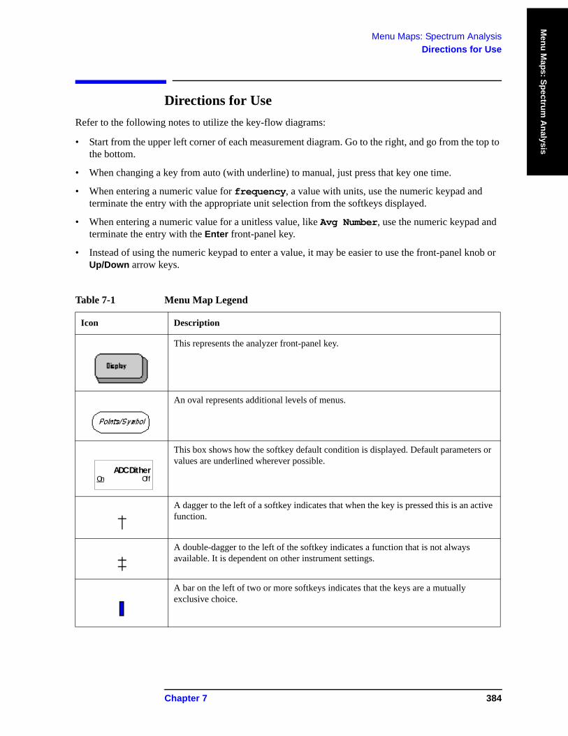
Menu Maps: Spectrum AnalysisDirections for Use
Menu M
aps: Spectrum A
nalysis
Directions for Use Refer to the following notes to utilize the key-flow diagrams:
• Start from the upper left corner of each measurement diagram. Go to the right, and go from the top to the bottom.
• When changing a key from auto (with underline) to manual, just press that key one time.
• When entering a numeric value for frequency, a value with units, use the numeric keypad and terminate the entry with the appropriate unit selection from the softkeys displayed.
• When entering a numeric value for a unitless value, like Avg Number, use the numeric keypad and terminate the entry with the Enter front-panel key.
• Instead of using the numeric keypad to enter a value, it may be easier to use the front-panel knob or Up/Down arrow keys.
Table 7-1 Menu Map Legend
Icon Description
This represents the analyzer front-panel key.
An oval represents additional levels of menus.
This box shows how the softkey default condition is displayed. Default parameters or values are underlined wherever possible.
A dagger to the left of a softkey indicates that when the key is pressed this is an active function.
A double-dagger to the left of the softkey indicates a function that is not always available. It is dependent on other instrument settings.
A bar on the left of two or more softkeys indicates that the keys are a mutually exclusive choice.
ADC DitherOn Off
Chapter 7 384
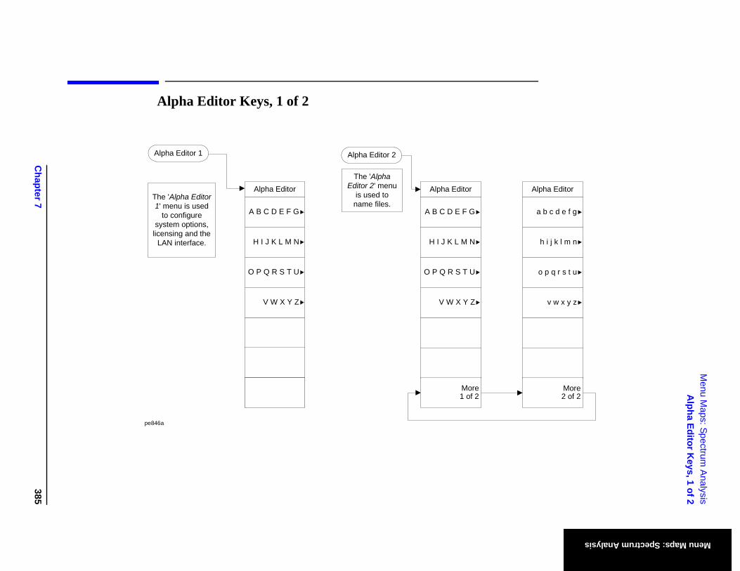
Chapter 7
385
Menu M
aps: Spectrum A
nalysisA
lpha Editor Keys, 1 of 2
Menu Maps: Spectrum Analysis
Alpha Editor
More2 of 2
a b c d e f g
h i j k l m n
o p q r s t u
v w x y z
Alpha Editor Keys, 1 of 2
Alpha Editor
A B C D E F G
H I J K L M N
O P Q R S T U
V W X Y Z
Alpha Editor 2
The 'Alpha Editor 2' menu
is used to name files.
More1 of 2
Alpha Editor
A B C D E F G
H I J K L M N
O P Q R S T U
V W X Y Z
Alpha Editor 1
The 'Alpha Editor 1' menu is used
to configure system options,
licensing and the LAN interface.
pe846a
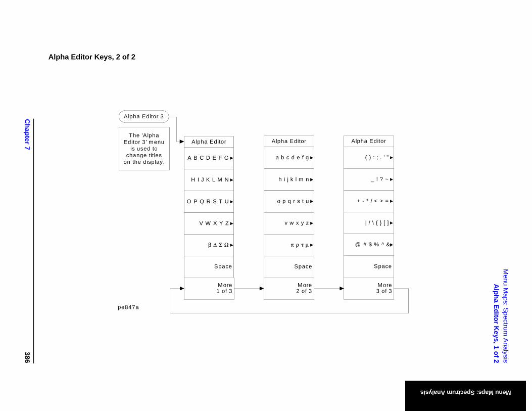
Chapter 7
386
Menu M
aps: Spectrum A
nalysisA
lpha Editor Keys, 1 of 2
Menu Maps: Spectrum Analysis
Space
Editor
) : ; . ' "
_ ! ? ~
/ < > =
\ { } [ ]
% ^ &
More3 of 3
Alpha Editor Keys, 2 of 2
Alpha Editor
Space
A B C D E F G
H I J K L M N
O P Q R S T U
V W X Y Z
β Δ Σ Ω
Alpha
(
+ - *
| /
@ # $
Space
Alpha Editor
a b c d e f g
h i j k l m n
o p q r s t u
v w x y z
π ρ τ μ
Alpha Editor 3
The 'Alpha Editor 3' menu
is used to change titles
on the display.
More1 of 3
More2 of 3
pe847a
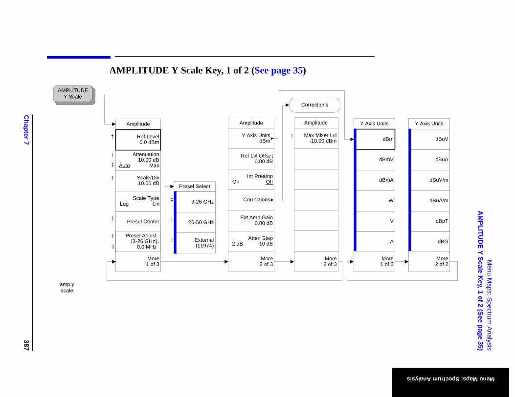
Chapter 7
387
Menu M
aps: Spectrum A
nalysisA
MPLITU
DE Y Scale K
ey, 1 of 2 (See page 35)
Menu Maps: Spectrum Analysis
Y Axis Units
dBmV
A
V
dBmA
W
dBm
More1 of 2
Y Axis Units
dBuA
dBG
dBpT
dBuV/m
dBuA/m
dBuV
More2 of 2
AMPLITUDE Y Scale Key, 1 of 2 (See page 35)
‡
†
†
†
†
†
†
AMPLITUDEY Scale
amp y scale
External(11974)
26-50 GHz
Presel Select
3-26 GHz
‡
‡
‡
‡
‡
‡
‡
Presel Center
Amplitude
Attenuation10.00 dB
Auto Man
Scale/Div10.00 dB
Scale TypeLog Lin
Presel Adjust [3-26 GHz]
0.0 MHz
Ref Level0.0 dBm
More1 of 3
Presel Adjust[3-26 GHz]
0.0 MHz
†
Amplitude
Max Mixer Lvl-10.00 dBm
More3 of 3
Corrections
Amplitude
Ref Lvl Offset0.00 dB
Int PreampOn Off
Ext Amp Gain0.00 dB
Atten Step2 dB 10 dB
Y Axis UnitsdBm
More2 of 3
Corrections
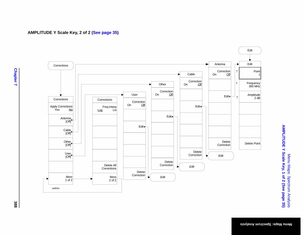
Chapter 7
388
Menu M
aps: Spectrum A
nalysisA
MPLITU
DE Y Scale K
ey, 1 of 2 (See page 35)
Menu Maps: Spectrum Analysis
DeleteCorrection
Edit
CorrectionOn Off
Antenna
Edit
Frequency300 MHz
Amplitude2 dB
Delete Point
†
†
†
Point1
Edit
Edit
AMPLITUDE Y Scale Key, 2 of 2 (See page 35)
DeleteCorrection
Edit
CorrectionOn Off
Corrections
DeleteCorrection
Edit
CorrectionOn Off
DeleteCorrection
Edit
CorrectionOn Off
User
Other
Cable
pe853a
Edit
Edit
Apply CorrectionsYes No
More1 of 2
Antenna[Off]
Cable[Off]
Other[Off]
User[Off]
Corrections
Freq InterpLog Lin
Delete All Corrections
More2 of 2
Corrections
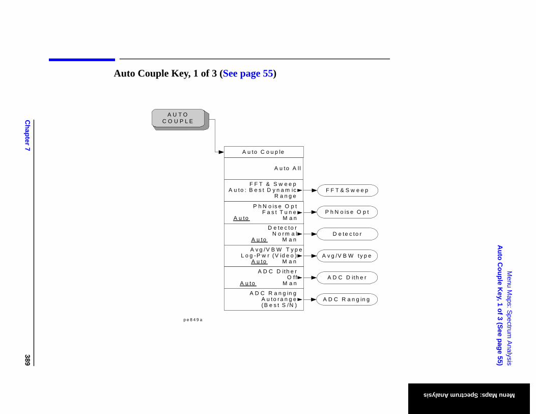
Chapter 7
389
Menu M
aps: Spectrum A
nalysisA
uto Couple K
ey, 1 of 3 (See page 55)
Menu Maps: Spectrum Analysis
Auto Couple Key, 1 of 3 (See page 55)
A U T O C O U P L E
p e 8 4 9 a
A v g /V B W ty p e
D e te c to r
P h N o is e O p t
F F T & S w e e p
A D C R a n g in g
A D C D ith e r
A u to C o u p le
A u to A l l
D e te c to rN o r m a l
A u to M a n
A v g /V B W T y p eL o g -P w r (V id e o )
A u to M a n
P h N o is e O p tF a s t T u n e
A u to M a n
F F T & S w e e pA u to : B e s t D y n a m ic
R a n g e
A D C R a n g in gA u to r a n g e( B e s t S /N )
A D C D ith e rO f f
A u to M a n
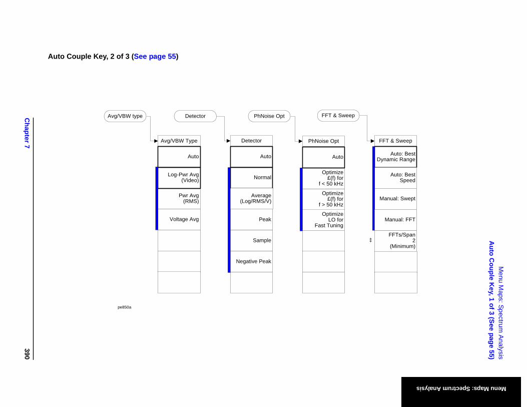
Chapter 7
390
Menu M
aps: Spectrum A
nalysisA
uto Couple K
ey, 1 of 3 (See page 55)
Menu Maps: Spectrum Analysis
FFT & Sweep
FFTs/Span2
(Minimum)
Auto: Best Dynamic Range
Auto: Best Speed
Manual: Swept
Manual: FFT
‡
Auto Couple Key, 2 of 3 (See page 55)
Avg/VBW Type
Auto
Pwr Avg(RMS)
Voltage Avg
Log-Pwr Avg(Video)
Detector
Auto
Peak
Sample
Negative Peak
Normal
PhNoise Opt
Optimize£(f) for
f > 50 kHz
Optimize£(f) for
f < 50 kHz
OptimizeLO for
Fast Tuning
Auto
Avg/VBW type Detector PhNoise Opt FFT & Sweep
pe850a
Average(Log/RMS/V)
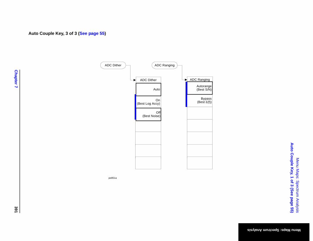
Chapter 7
391
Menu M
aps: Spectrum A
nalysisA
uto Couple K
ey, 1 of 3 (See page 55)
Menu Maps: Spectrum Analysis
Auto Couple Key, 3 of 3 (See page 55)
ADC Dither
ADC Dither
On(Best Log Accy)
ADC Ranging
ADC Ranging
Bypass(Best £(f))
Autorange(Best S/N)
pe851a
Auto
Off(Best Noise)
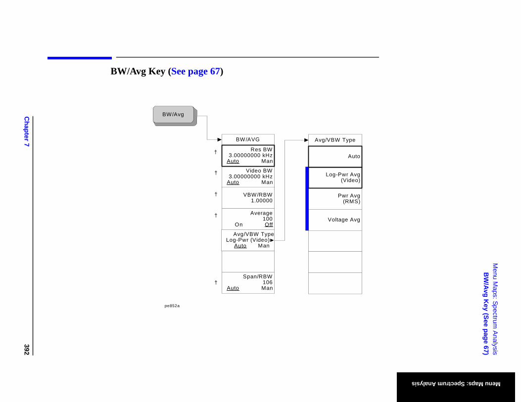
Chapter 7
392
Menu M
aps: Spectrum A
nalysisB
W/Avg K
ey (See page 67)
Menu Maps: Spectrum Analysis
BW/Avg Key (See page 67)
†
†
†
†
BW/Avg
pe852a
†
Avg/VBW Type Log-Pwr (Video)
Auto Man
BW/AVG
Span/RBW106
Auto Man
Video BW3.00000000 kHz
Auto Man
VBW/RBW 1.00000
Average100
On Off
Res BW3.00000000 kHz
Auto Man
Avg/VBW Type
Auto
Pwr Avg(RMS)
Voltage Avg
Log-Pwr Avg(Video)
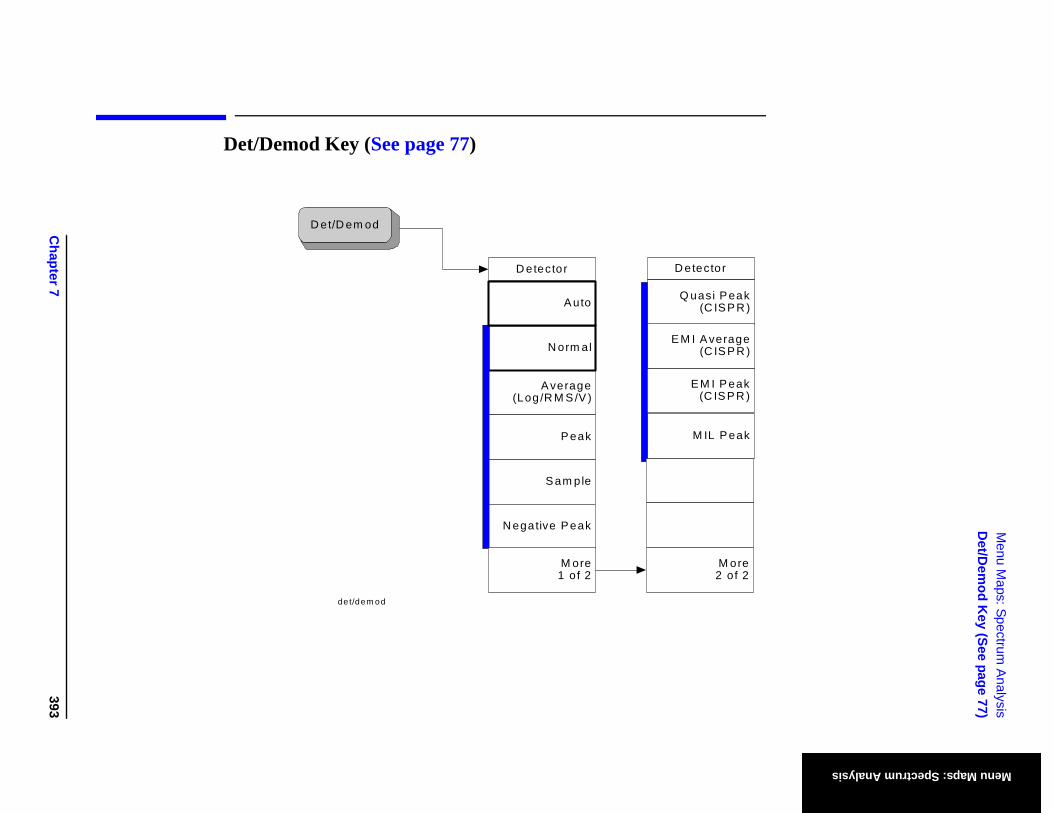
Chapter 7
393
Menu M
aps: Spectrum A
nalysisD
et/Dem
od Key (See page 77)
Menu Maps: Spectrum Analysis
akR )
ak
akR )
ge R )
ref 2
Det/Demod Key (See page 77)
D etector
A verage(Log /R M S /V )
S am ple
N egative P eak
P eak
N orm al
D et/D em od
A uto
det/dem od
M ore1 of 2
D etector
E M I P e(C IS P
M IL P e
Q uasi P e(C IS P
E M I A vera(C IS P
M o2 o
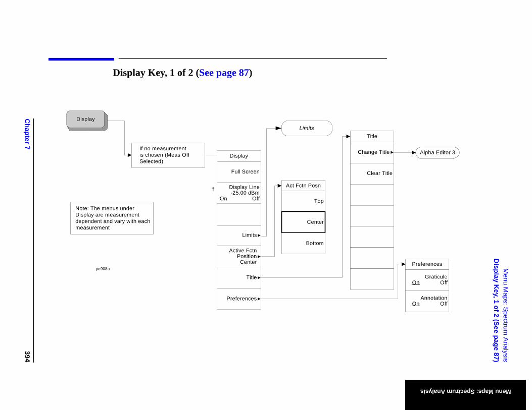
Chapter 7
394
Menu M
aps: Spectrum A
nalysisD
isplay Key, 1 of 2 (See page 87)
Menu Maps: Spectrum Analysis
itle
lear Title
ge Title Alpha Editor 3
GraticuleOn Off
AnnotationOn Off
Preferences
Display Key, 1 of 2 (See page 87)
T
C
Chan
Display
If no measurementis chosen (Meas OffSelected)
Note: The menus underDisplay are measurementdependent and vary with each measurement
Limits
pe908a
†
Display
Display Line-25.00 dBm
On Off
Title
Full Screen
Preferences
Limits
Active Fctn Position
Center
Top
Center
Act Fctn Posn
Bottom

Chapter 7
395
Menu M
aps: Spectrum A
nalysisD
isplay Key, 1 of 2 (See page 87)
Menu Maps: Spectrum Analysis
†
†
†
Point1
Frequency300 MHz
Amplitude2 dB
Delete Point
Connected To Previous Pt
Yes No
Edit
Display Key, 2 of 2 (See page 87)
Limit TestOn Off
X Axis UnitsFreq Time
TypeUpper Lower
LimitsFixed Rel
Delete All Limits
Limits
Edit
Limits
Amptd InterpLog Lin
Freq InterpLog Lin
Delete Limit
Margin0.0 dB
On Off
More1 of 2
Limit DisplayOn Off
Limit 1[Upper]
Limit 2[Upper]
More2 of 2
Limit 1 Limit 1
†
‡
Freq Interp key: grayed out in Time Limits
Limits (Display-2)
Same as Limit 1 (above) but menu title is "Limit 2"
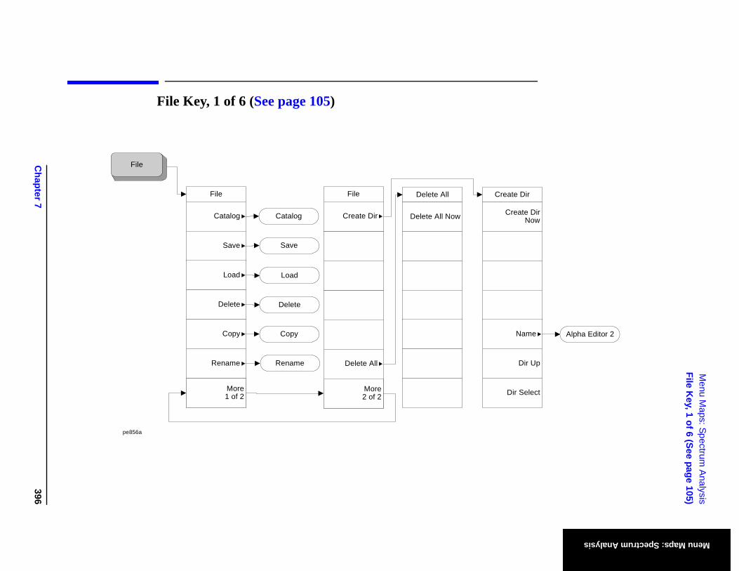
Chapter 7
396
Menu M
aps: Spectrum A
nalysisFile K
ey, 1 of 6 (See page 105)
Menu Maps: Spectrum Analysis
e Dir
eate DirNow
Dir Up
ir Select
Name Alpha Editor 2
File Key, 1 of 6 (See page 105)
File
Rename
Catalog
Save
Load
Delete
Copy
More1 of 2
Save
Load
Delete
Copy
Rename
Delete All
Delete All Now
Creat
Cr
D
File
File
Create Dir
Delete All
More2 of 2
Catalog
pe856a
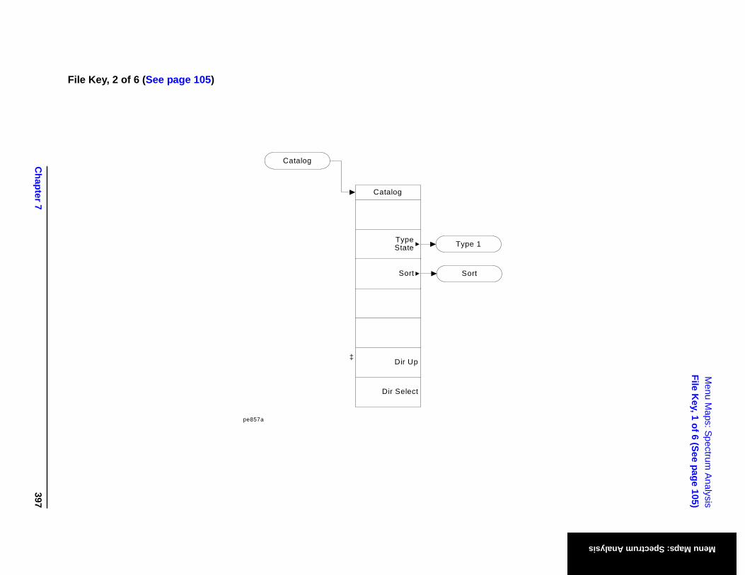
Chapter 7
397
Menu M
aps: Spectrum A
nalysisFile K
ey, 1 of 6 (See page 105)
Menu Maps: Spectrum Analysis
File Key, 2 of 6 (See page 105)
‡
Sort
Type 1
Catalog
pe857a
Catalog
Dir Up
Dir Select
TypeState
Sort
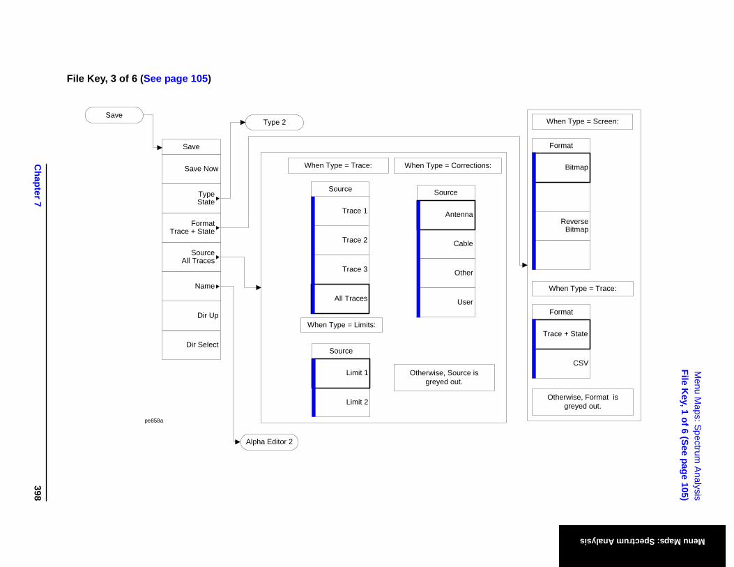
Chapter 7
398
Menu M
aps: Spectrum A
nalysisFile K
ey, 1 of 6 (See page 105)
Menu Maps: Spectrum Analysis
When Type = Screen:
When Type = Trace:
Otherwise, Format is greyed out.
Format
ReverseBitmap
Bitmap
Format
CSV
Trace + State
File Key, 3 of 6 (See page 105)
Save
Save Now
Dir Up
Save
Dir Select
TypeState
FormatTrace + State
SourceAll Traces
Name
Alpha Editor 2
When Type = Trace:
Otherwise, Source is greyed out.
Source
Trace 2
Trace 3
Trace 1
All Traces
Type 2
When Type = Corrections:
Source
Cable
Other
Antenna
User
When Type = Limits:
Source
Limit 2
Limit 1
pe858a
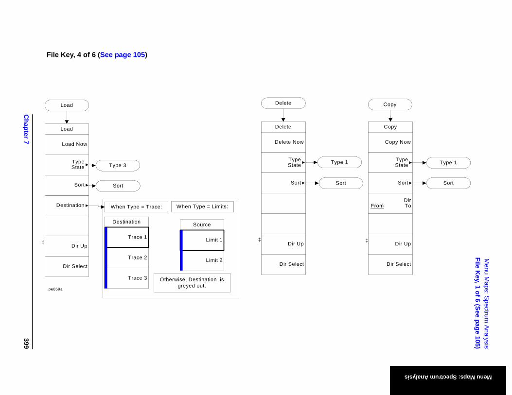
Chapter 7
399
Menu M
aps: Spectrum A
nalysisFile K
ey, 1 of 6 (See page 105)
Menu Maps: Spectrum Analysis
‡ ‡
Copy
Copy Now
Copy
Dir Up
Dir Select
DirFrom To
TypeState
Sort Sort
Type 1
File Key, 4 of 6 (See page 105)
Sort
Sort
By Size
By Name
By Extension
OrderUp
Down
By Date
Rename
Rename Now
Rename
Dir Up
Dir Select
Name
TypeState
Sort Sort
Type 1
Alpha Editor 2
File (4)
Load
Load Now
Load
Dir Up
Dir Select
Destination
Sort
TypeState
When Type = Trace:
Destination
Trace 2
Trace 3
Trace 1
Otherwise, Destination is greyed out.
Type 3
Sort
‡
Delete
Delete Now
Delete
Dir Up
Dir Select
TypeState
Sort
Type 1
Sort
When Type = Limits:
Source
Limit 2
Limit 1
pe859a
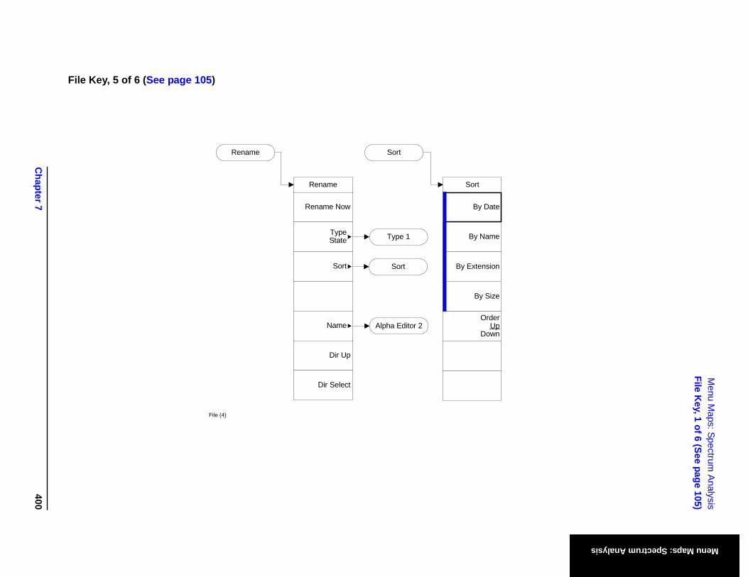
Chapter 7
400
Menu M
aps: Spectrum A
nalysisFile K
ey, 1 of 6 (See page 105)
Menu Maps: Spectrum Analysis
File Key, 5 of 6 (See page 105)
Sort
Sort
By Size
By Name
By Extension
OrderUp
Down
By Date
Rename
Rename Now
Rename
Dir Up
Dir Select
Name
TypeState
Sort Sort
Type 1
Alpha Editor 2
File (4)
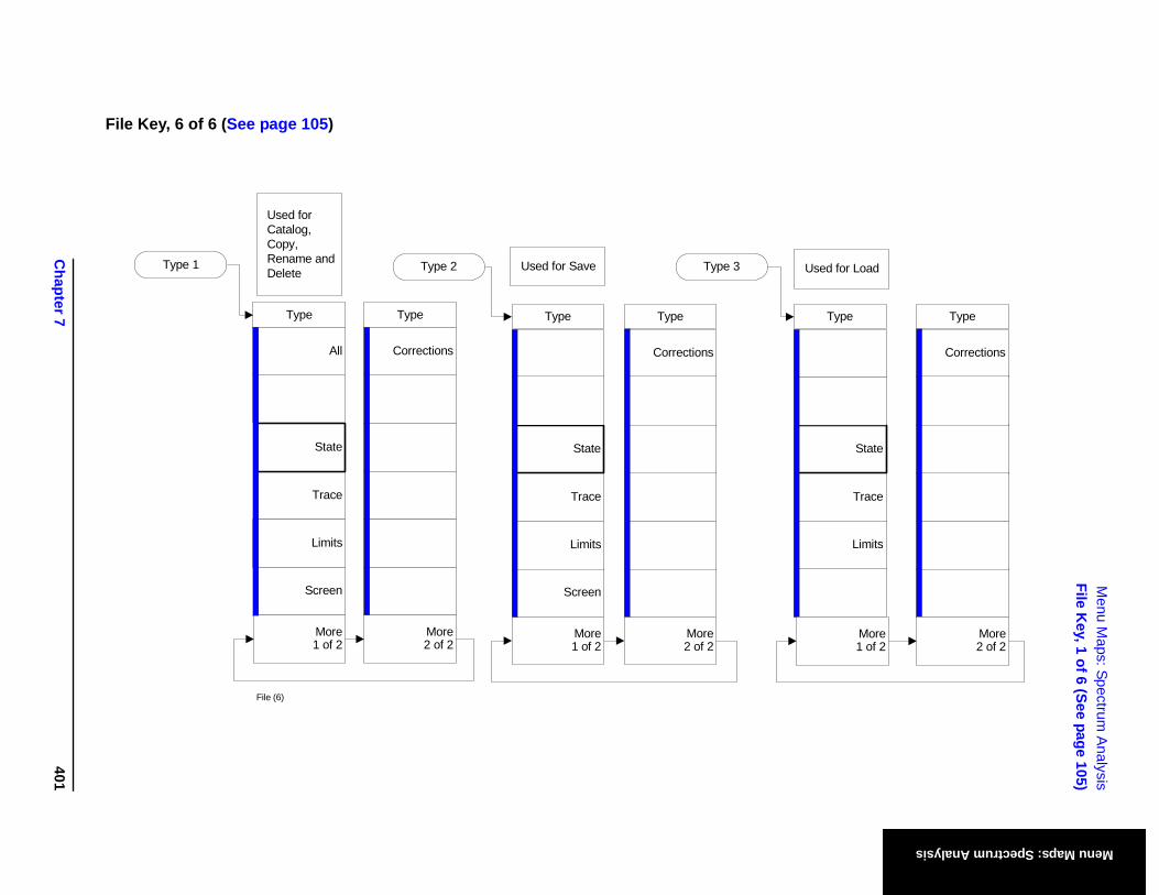
Chapter 7
401
Menu M
aps: Spectrum A
nalysisFile K
ey, 1 of 6 (See page 105)
Menu Maps: Spectrum Analysis
Type
Trace
State
Limits
Used for Load
Type
Corrections
More1 of 2
More2 of 2
File Key, 6 of 6 (See page 105)
Type 3
Type
Trace
Screen
State
Type 2
Type
All
Trace
Screen
State
Type 1
More1 of 2
Limits
More1 of 2
Limits
Type
Corrections
More2 of 2
Type
Corrections
More2 of 2
Used for Catalog, Copy, Rename and Delete Used for Save
File (6)
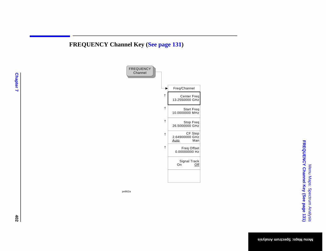
Chapter 7
402
Menu M
aps: Spectrum A
nalysisFR
EQU
ENC
Y Channel K
ey (See page 131)
Menu Maps: Spectrum Analysis
FREQUENCY Channel Key (See page 131)
†
†
†
†
†
FREQUENCY Channel
pe862a
Freq/Channel
Stop Freq26.5000000 GHz
Start Freq10.0000000 MHz
CF Step2.64900000 GHzAuto Man
Freq Offset0.00000000 Hz
Signal TrackOn Off
Center Freq13.2550000 GHz
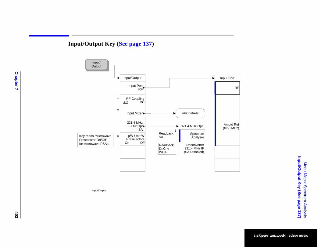
Chapter 7
403
Menu M
aps: Spectrum A
nalysisInput/O
utput Key (See page 137)
Menu Maps: Spectrum Analysis
put Port
Amptd Ref(f=50 MHz)
RF
Input/Output Key (See page 137)
InInput/Output
Input PortRF
RF CouplingAC DC
Input/ Output
Input/Output
Input MixerInput Mixer
321.4 MHz IF Out Opt
SASpectrum Analyzer
Dnconverter 321.4 MHz IF(SA Disabled)
321.4 MHz Opt
μW / mmW Preselectors
On Off
Key reads “Microwave Preselector On/Off” for microwave PSAs.
Readback:SA
Readback:DnCnv WBIF
‡‡
‡
‡
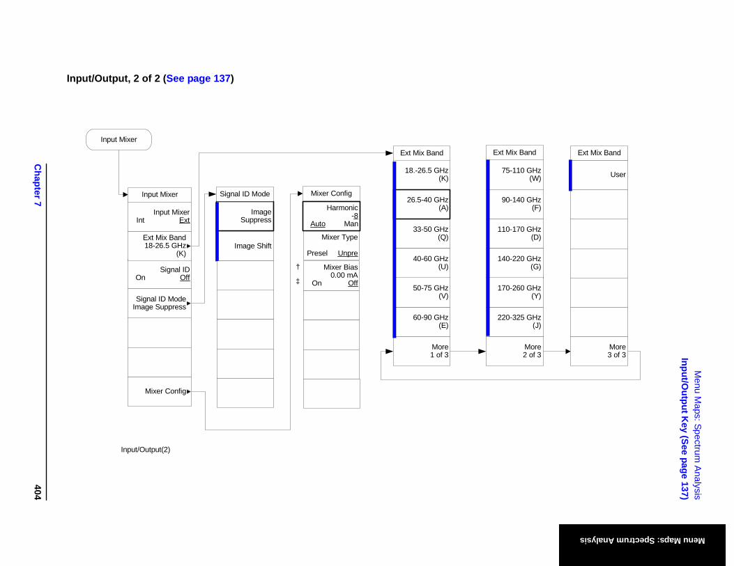
Chapter 7
404
Menu M
aps: Spectrum A
nalysisInput/O
utput Key (See page 137)
Menu Maps: Spectrum Analysis
-110 GHz(W)
-170 GHz(D)
-140 GHz(F)
-220 GHz(G)
-325 GHz(J)
-260 GHz(Y)
More2 of 3
User
ix Band Ext Mix Band
More3 of 3
Input/Output, 2 of 2 (See page 137)
Input/Output(2)
Image Suppress
Image Shift
Signal ID Mode
Mixer Type
Presel Unpre
Harmonic-8
Auto Man
Mixer Bias0.00 mA
On Off
†
‡
Mixer Config
18.-26.5 GHz(K)
33-50 GHz(Q)
26.5-40 GHz(A)
40-60 GHz(U)
60-90 GHz(E)
50-75 GHz(V)
More1 of 3
75
110
90
140
220
170
Ext Mix Band Ext M
Input Mixer
Mixer Config
Signal IDOn Off
Signal ID ModeImage Suppress
Input Mixer
Ext Mix Band18-26.5 GHz
(K)
Input MixerInt Ext
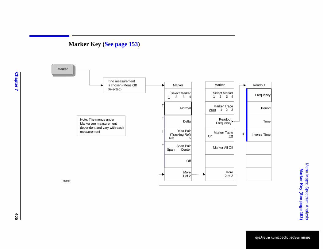
Chapter 7
405
Menu M
aps: Spectrum A
nalysisM
arker Key (See page 153)
Menu Maps: Spectrum Analysis
Readout
Period
Time
Frequency
Inverse Time‡
arker 3 4
Trace 2 3
doutency
Table Off
All Off
More2 of 2
Marker Key (See page 153)
Marker
†
†
†
†
Marker
If no measurementis chosen (Meas OffSelected)
Note: The menus underMarker are measurementdependent and vary with each measurement
Marker
Delta
Select Marker1 2 3 4
Normal
Off
Delta Pair(Tracking Ref)Ref Δ
Span PairSpan Center
More1 of 2
Marker
Select M1 2
Marker Auto 1
ReaFrequ
Marker On
Marker
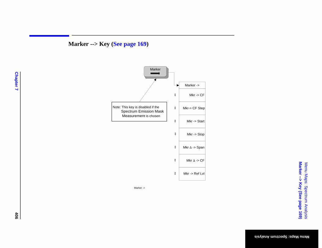
Chapter 7
406
Menu M
aps: Spectrum A
nalysisM
arker --> Key (See page 169)
Menu Maps: Spectrum Analysis
Marker --> Key (See page 169)
‡
Marker ->
Mkr -> Start
Mkr -> CF
Mkr-> CF Step
Mkr Δ -> Span
Mkr -> Stop
Mkr -> Ref Lvl
Marker
Mkr Δ -> CF‡
‡
‡
‡
‡
‡
Note: This key is disabled if the Spectrum Emission Mask Measurement is chosen
Marker ->
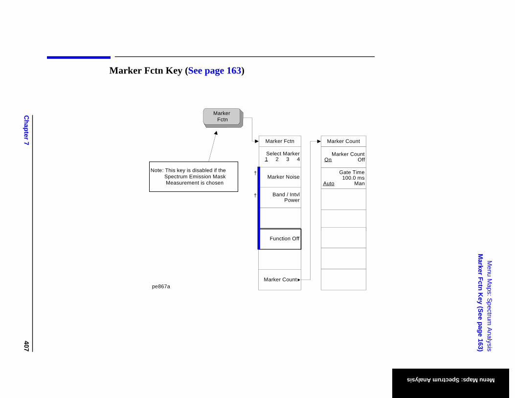
Chapter 7
407
Menu M
aps: Spectrum A
nalysisM
arker Fctn Key (See page 163)
Menu Maps: Spectrum Analysis
t
untOff
emsan
Marker Fctn Key (See page 163)
†
Marker Fctn
Function Off
Select Marker1 2 3 4
Band / IntvlPower
Marker Noise
Marker Count
Marker Fctn
pe867a
†
Note: This key is disabled if the Spectrum Emission Mask Measurement is chosen
Marker Coun
Marker CoOn
Gate Tim100.0
Auto M
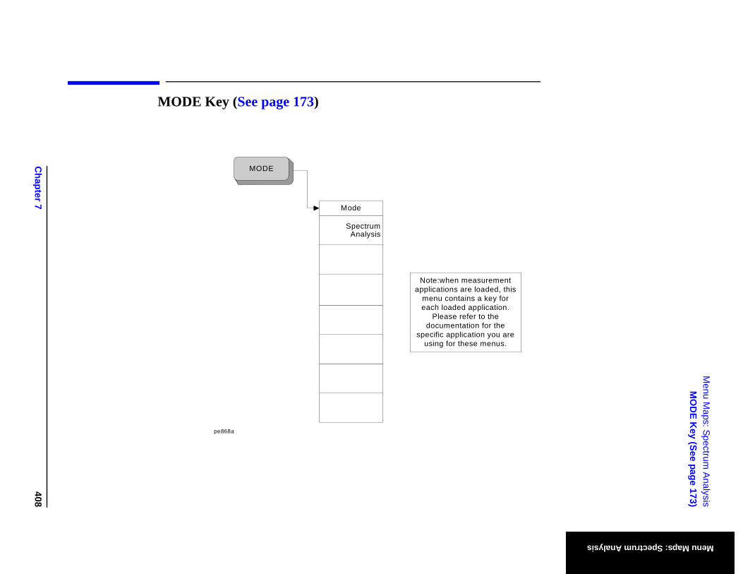
Chapter 7
408
Menu M
aps: Spectrum A
nalysisM
OD
E Key (See page 173)
Menu Maps: Spectrum Analysis
MODE Key (See page 173)
Mode
Spectrum Analysis
MODE
pe868a
Note:when measurement applications are loaded, this
menu contains a key for each loaded application.
Please refer to the documentation for the
specific application you are using for these menus.
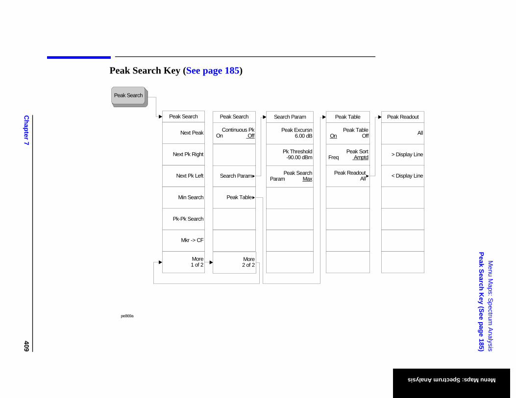
Chapter 7
409
Menu M
aps: Spectrum A
nalysisPeak Search K
ey (See page 185)
Menu Maps: Spectrum Analysis
able Off
Sortptd
outAll
Peak Readout
All
> Display Line
< Display Line
Peak Search Key (See page 185)
Peak Search
pe869a
Peak Table
Peak TOn
Peak Freq Am
Peak Read
Search Param
Peak Excursn6.00 dB
Pk Threshold-90.00 dBm
Peak SearchParam Max
Peak Search
Search Param
Continuous PkOn Off
More2 of 2
Peak Table
Peak Search
Next Pk Right
Pk-Pk Search
Next Peak
Next Pk Left
Min Search
Mkr -> CF
More1 of 2
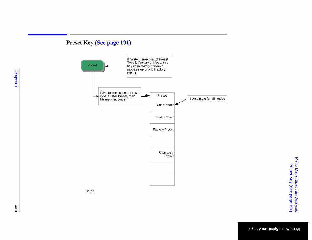
Chapter 7
410
Menu M
aps: Spectrum A
nalysisPreset K
ey (See page 191)
Menu Maps: Spectrum Analysis
odes
Preset Key (See page 191)
Preset
If System selection of Preset Type is Factory or Mode, this key immediately performs mode setup or a full factory preset.
If System selection of Preset Type is User Preset, then this menu appears.
Preset
User Preset
Mode Preset
Factory Preset
Save User Preset
pe870a
Saves state for all m
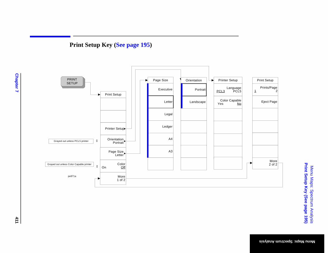
Chapter 7
411
Menu M
aps: Spectrum A
nalysisPrint Setup K
ey (See page 195)
Menu Maps: Spectrum Analysis
Eject Page
Prints/Page1 2
More2 of 2
Print Setup Setup
anguage PCL5
Capable No
Print Setup Key (See page 195)
Print Setup
Printer Setup
OrientationPortrait
ColorOn Off
PRINT SETUP
Page SizeLetter
More1 of 2
‡
‡
Grayed out unless PCL5 printer
Grayed out unless Color Capable printer
pe871a
Executive
Letter
Legal
Ledger
A4
A3
Page Size Printer
LPCL3
ColorYes
Orientation
Landscape
Portrait
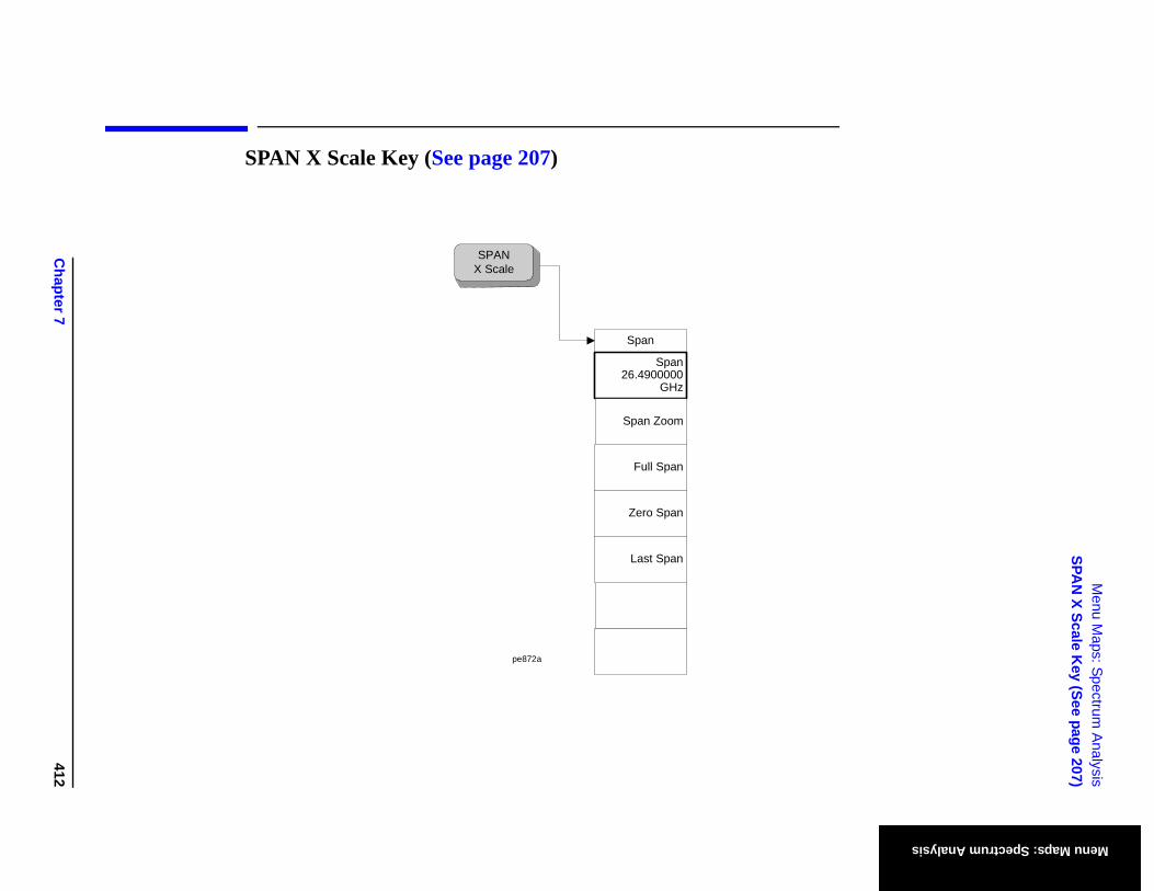
Chapter 7
412
Menu M
aps: Spectrum A
nalysisSPA
N X Scale K
ey (See page 207)
Menu Maps: Spectrum Analysis
SPAN X Scale Key (See page 207)
Span
Full Span
Zero Span
Last Span
Span26.4900000
GHz
SPANX Scale
Span Zoom
pe872a
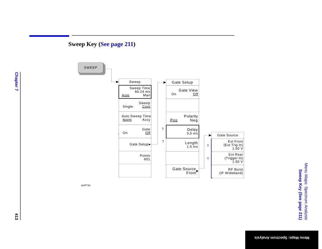
Chapter 7
413
Menu M
aps: Spectrum A
nalysisSw
eep Key (See page 211)
Menu Maps: Spectrum Analysis
RF Burst Wideband)
Ext Front(Ext Trig In)
1.50 V
Ext Rear(Trigger In)
1.50 V
e Source
Sweep Key (See page 211)
pe873a
†
†‡
SWEEP
†
†
Gate Setup
GateOn Off
Sweep
SweepSingle Cont
Sweep Time66.24 ms
Auto Man
Points601
Auto Sweep TimeNorm Accy
PolarityPos Neg
Delay3.0 ms
Length1.5 ms
Gate Setup
Gate ViewOn Off
Gate SourceFront (IF
Gat
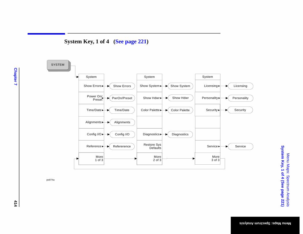
Chapter 7
414
Menu M
aps: Spectrum A
nalysisSystem
Key, 1 of 4 (See page 221)
Menu Maps: Spectrum Analysis
m
More3 of 3
sing
rvice Service
Licensing
nality Personality
urity Security
System Key, 1 of 4 (See page 221)
System
More2 of 3
Color Palette
Diagnostics
Restore Sys Defaults
Show System
System
Show Errors
Power On/Preset
Time/Date
Alignments
Config I/O
More1 of 3
SYSTEM
Syste
Licen
Se
Alignments
Config I/O
Color Palette
Diagnostics
Show System
Time/Date
Show Errors
PwrOn/Preset
pe874a
Show Hdwr
Reference Refererence
PersoShow Hdwr
Sec
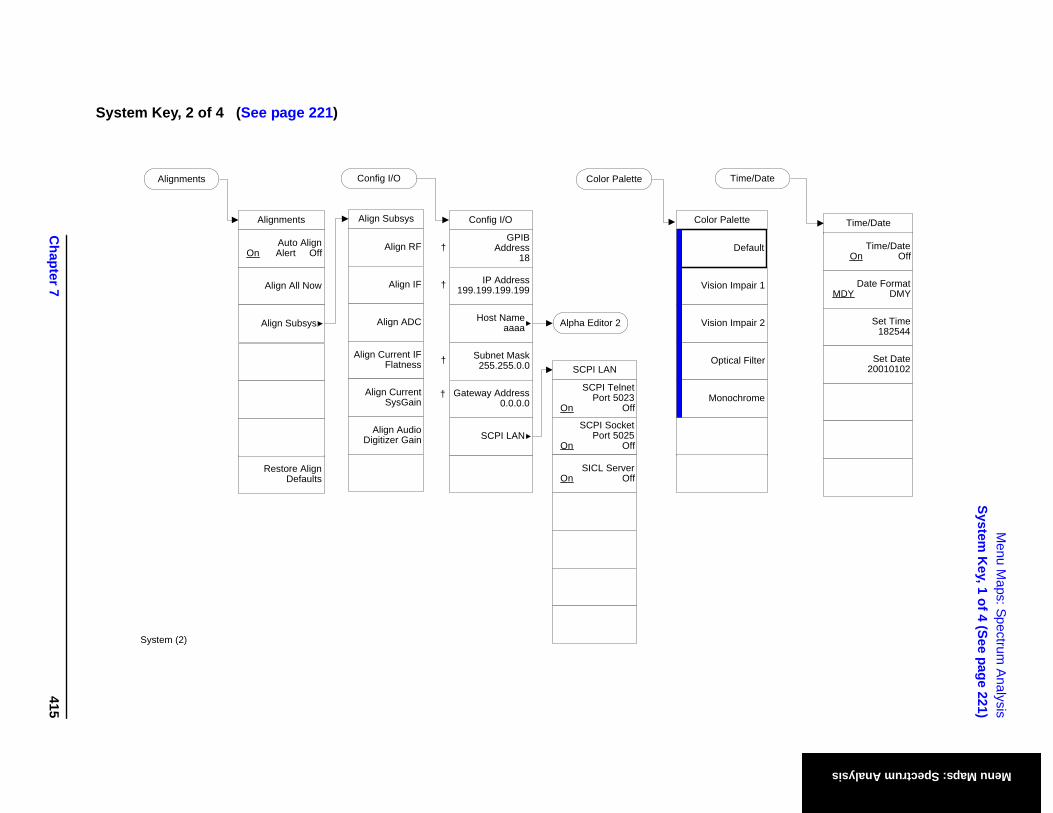
Chapter 7
415
Menu M
aps: Spectrum A
nalysisSystem
Key, 1 of 4 (See page 221)
Menu Maps: Spectrum Analysis
ime/Date
Time/Date
Time/DateOn Off
Date FormatMDY DMY
Set Time182544
Set Date20010102
lette
mpair 1
al Filter
mpair 2
chrome
Default
System Key, 2 of 4 (See page 221)
Color PaletteAlignments
Align Subsys
Align RF
Align IF
Align ADC
Align Current IF Flatness
Align Current SysGain
Align AudioDigitizer Gain
Config I/O
Alpha Editor 2
System (2)
T
Alignments
Restore Align Defaults
Align All Now
Auto AlignOn Alert Off
Align Subsys
SCPI LAN
SCPI TelnetPort 5023
On Off
SCPI SocketPort 5025
On Off
SICL ServerOn Off
Color Pa
Vision I
Optic
Vision I
Mono
GPIB Address
18
Config I/O
Host Nameaaaa
SCPI LAN
IP Address199.199.199.199†
†
Subnet Mask255.255.0.0†
Gateway Address0.0.0.0
†

Chapter 7
416
Menu M
aps: Spectrum A
nalysisSystem
Key, 1 of 4 (See page 221)
Menu Maps: Spectrum Analysis
Alpha Editor 1
Alpha Editor 1
Reference
Show License
Freq Ref10.0000000 MHz
Int Ext
10 MHz OutOff On
Reference
System Key, 3 of 4 (See page 221)
Diagnostics
Diagnostics
Front Panel Test
Licensing
Licensing
Delete License
Activate License
Option
License Key
System (3)
Show License
PwrOn/Preset
Save User Preset
Power OnLast Preset
PwrOn/Preset
Preset TypeMode
User
Mode
Factory
Preset Type
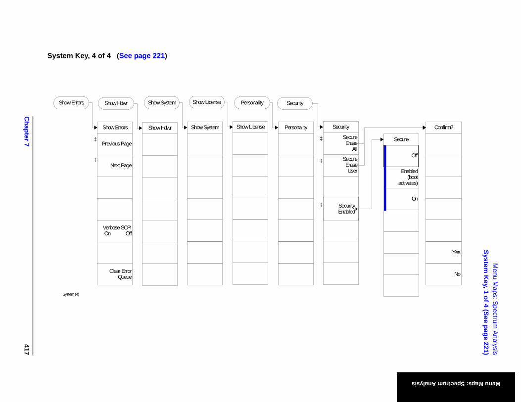
Chapter 7
417
Menu M
aps: Spectrum A
nalysisSystem
Key, 1 of 4 (See page 221)
Menu Maps: Spectrum Analysis
Confirm?
Yes
No
Secure
On
Enabled(boot
activates)
Off
System Key, 4 of 4 (See page 221)
‡
‡
Show Errors
Previous Page
Next Page
Verbose SCPI On Off
Clear Error Queue
Show Errors
System (4)
Show Hdwr
Show Hdwr
Show System
Show System
Show License
Show License
Personality
Personality
Security
SecureErase
All
Secure EraseUser
Security
‡
‡
SecurityEnabled
‡
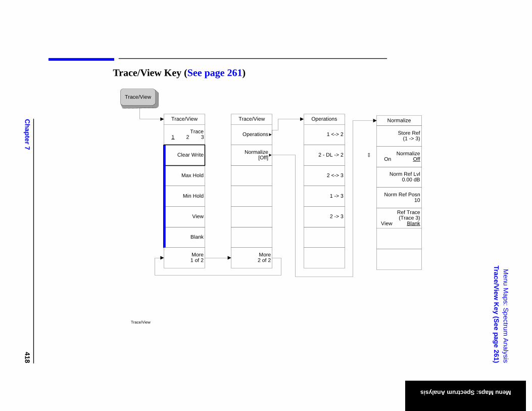
Chapter 7
418
Menu M
aps: Spectrum A
nalysisTrace/View
Key (See page 261)
Menu Maps: Spectrum Analysis
Normalize
Ref Trace(Trace 3)
View Blank
Norm Ref Lvl0.00 dB
Norm Ref Posn10
Store Ref(1 -> 3)
NormalizeOn Off
Trace/View Key (See page 261)
Trace/View
Trace/View
Blank
View
Max Hold
Min Hold
Trace1 2 3
Clear Write
Trace/View
More1 of 2
Trace/View
More2 of 2
Operations
Normalize[Off]
Operations
2 -> 3
2 <-> 3
1 -> 3
1 <-> 2
2 - DL -> 2 ‡
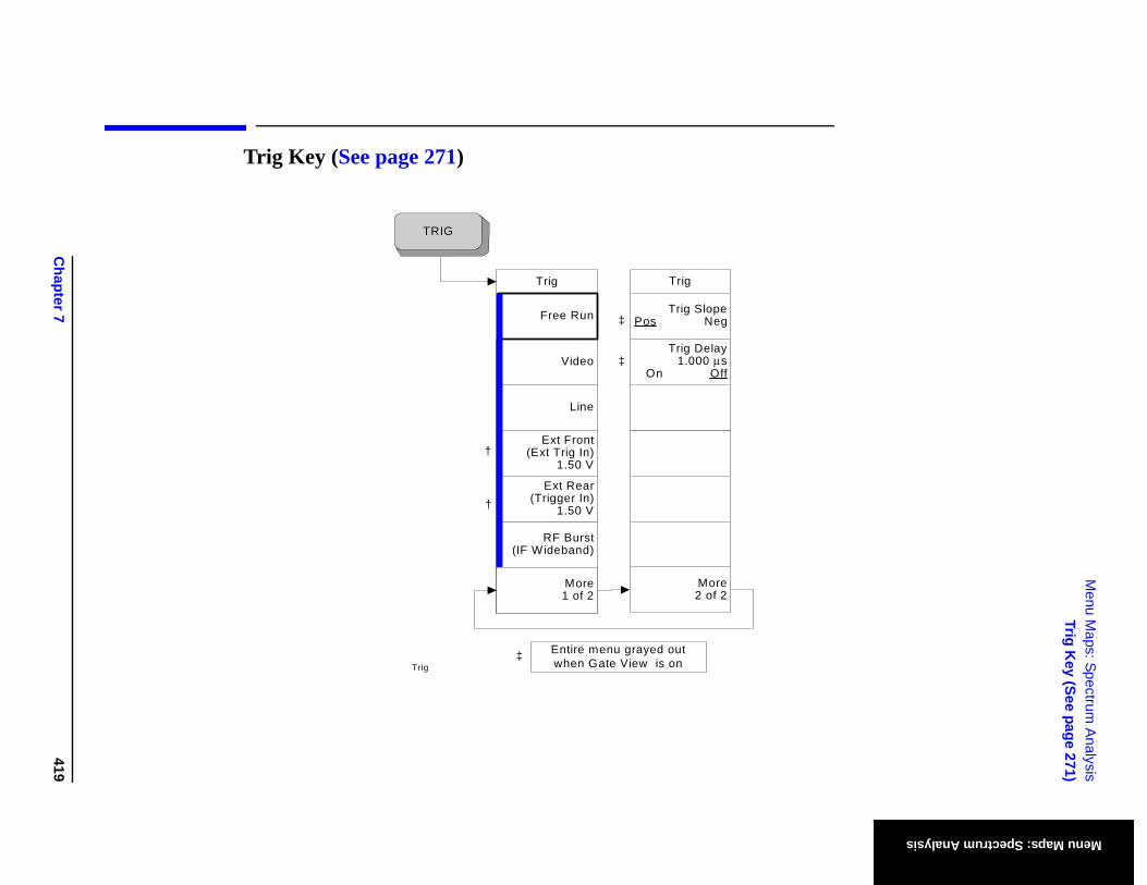
Chapter 7
419
Menu M
aps: Spectrum A
nalysisTrig K
ey (See page 271)
Menu Maps: Spectrum Analysis
Trig Key (See page 271)
Trig
RF Burst(IF Wideband)
More1 of 2
Video
Line
Free Run
TRIG
Trig
‡
‡
Ext Front(Ext Trig In)
1.50 V
Ext Rear(Trigger In)
1.50 V
†
†
Entire menu grayed out when Gate View is on‡
Trig
More2 of 2
Trig SlopePos Neg
Trig Delay1.000 μs
On Off

Chapter 7
420
Menu M
aps: Spectrum A
nalysisTrig K
ey (See page 271)
Menu Maps: Spectrum Analysis
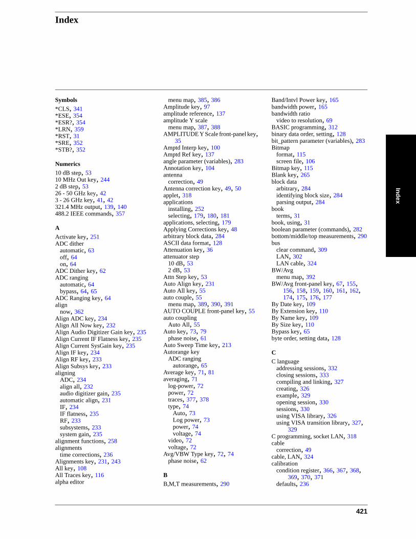
IndexIndex
Symbols*CLS, 341*ESE, 354*ESR?, 354*LRN, 359*RST, 31*SRE, 352*STB?, 352
Numerics10 dB step, 5310 MHz Out key, 2442 dB step, 5326 - 50 GHz key, 423 - 26 GHz key, 41, 42321.4 MHz output, 139, 140488.2 IEEE commands, 357
AActivate key, 251ADC dither
automatic, 63off, 64on, 64
ADC Dither key, 62ADC ranging
automatic, 64bypass, 64, 65
ADC Ranging key, 64align
now, 362Align ADC key, 234Align All Now key, 232Align Audio Digitizer Gain key, 235Align Current IF Flatness key, 235Align Current SysGain key, 235Align IF key, 234Align RF key, 233Align Subsys key, 233aligning
ADC, 234align all, 232audio digitizer gain, 235automatic align, 231IF, 234IF flatness, 235RF, 233subsystems, 233system gain, 235
alignment functions, 258alignments
time corrections, 236Alignments key, 231, 243All key, 108All Traces key, 116alpha editor
menu map, 385, 386Amplitude key, 97amplitude reference, 137amplitude Y scale
menu map, 387, 388AMPLITUDE Y Scale front-panel key,
35Amptd Interp key, 100Amptd Ref key, 137angle parameter (variables), 283Annotation key, 104antenna
correction, 49Antenna correction key, 49, 50applet, 318applications
installing, 252selecting, 179, 180, 181
applications, selecting, 179Applying Corrections key, 48arbitrary block data, 284ASCII data format, 128Attenuation key, 36attenuator step
10 dB, 532 dB, 53
Attn Step key, 53Auto Align key, 231Auto All key, 55auto couple, 55
menu map, 389, 390, 391AUTO COUPLE front-panel key, 55auto coupling
Auto All, 55Auto key, 73, 79
phase noise, 61Auto Sweep Time key, 213Autorange key
ADC rangingautorange, 65
Average key, 71, 81averaging, 71
log-power, 72power, 72traces, 377, 378type, 74
Auto, 73Log power, 73power, 74voltage, 74
video, 72voltage, 72
Avg/VBW Type key, 72, 74phase noise, 62
BB,M,T measurements, 290
Band/Intvl Power key, 165bandwidth power, 165bandwidth ratio
video to resolution, 69BASIC programming, 312binary data order, setting, 128bit_pattern parameter (variables), 283Bitmap
format, 115screen file, 106
Bitmap key, 115Blank key, 265block data
arbitrary, 284identifying block size, 284parsing output, 284
bookterms, 31
book, using, 31boolean parameter (commands), 282bottom/middle/top measurements, 290bus
clear command, 309LAN, 302LAN cable, 324
BW/Avgmenu map, 392
BW/Avg front-panel key, 67, 155, 156, 158, 159, 160, 161, 162, 174, 175, 176, 177
By Date key, 109By Extension key, 110By Name key, 109By Size key, 110Bypass key, 65byte order, setting data, 128
CC language
addressing sessions, 332closing sessions, 333compiling and linking, 327creating, 326example, 329opening session, 330sessions, 330using VISA library, 326using VISA transition library, 327,
329C programming, socket LAN, 318cable
correction, 49cable, LAN, 324calibration
condition register, 366, 367, 368, 369, 370, 371
defaults, 236
421
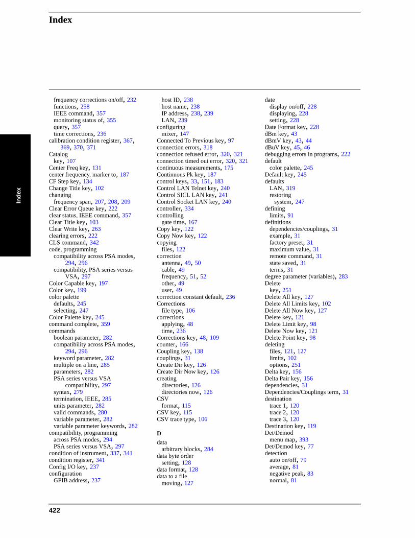
IndexIn
dex
frequency corrections on/off, 232functions, 258IEEE command, 357monitoring status of, 355query, 357time corrections, 236
calibration condition register, 367, 369, 370, 371
Catalogkey, 107
Center Freq key, 131center frequency, marker to, 187CF Step key, 134Change Title key, 102changing
frequency span, 207, 208, 209Clear Error Queue key, 222clear status, IEEE command, 357Clear Title key, 103Clear Write key, 263clearing errors, 222CLS command, 342code, programming
compatibility across PSA modes, 294, 296
compatibility, PSA series versus VSA, 297
Color Capable key, 197Color key, 199color palette
defaults, 245selecting, 247
Color Palette key, 245command complete, 359commands
boolean parameter, 282compatibility across PSA modes,
294, 296keyword parameter, 282multiple on a line, 285parameters, 282PSA series versus VSA
compatibility, 297syntax, 279termination, IEEE, 285units parameter, 282valid commands, 280variable parameter, 282variable parameter keywords, 282
compatibility, programmingacross PSA modes, 294PSA series versus VSA, 297
condition of instrument, 337, 341condition register, 341Config I/O key, 237configuration
GPIB address, 237
host ID, 238host name, 238IP address, 238, 239LAN, 239
configuringmixer, 147
Connected To Previous key, 97connection errors, 318connection refused error, 320, 321connection timed out error, 320, 321continuous measurements, 175Continuous Pk key, 187control keys, 33, 151, 183Control LAN Telnet key, 240Control SICL LAN key, 241Control Socket LAN key, 240controller, 334controlling
gate time, 167Copy key, 122Copy Now key, 122copying
files, 122correction
antenna, 49, 50cable, 49frequency, 51, 52other, 49user, 49
correction constant default, 236Corrections
file type, 106corrections
applying, 48time, 236
Corrections key, 48, 109counter, 166Coupling key, 138couplings, 31Create Dir key, 126Create Dir Now key, 126creating
directories, 126directories now, 126
CSVformat, 115
CSV key, 115CSV trace type, 106
Ddata
arbitrary blocks, 284data byte order
setting, 128data format, 128data to a file
moving, 127
datedisplay on/off, 228displaying, 228setting, 228
Date Format key, 228dBm key, 43dBmV key, 43, 44dBuV key, 45, 46debugging errors in programs, 222default
color palette, 245Default key, 245defaults
LAN, 319restoring
system, 247defining
limits, 91definitions
dependencies/couplings, 31example, 31factory preset, 31maximum value, 31remote command, 31state saved, 31terms, 31
degree parameter (variables), 283Delete
key, 251Delete All key, 127Delete All Limits key, 102Delete All Now key, 127Delete key, 121Delete Limit key, 98Delete Now key, 121Delete Point key, 98deleting
files, 121, 127limits, 102options, 251
Delta key, 156Delta Pair key, 156dependencies, 31Dependencies/Couplings term, 31destination
trace 1, 120trace 2, 120trace 3, 120
Destination key, 119Det/Demod
menu map, 393Det/Demod key, 77detection
auto on/off, 79average, 81negative peak, 83normal, 81
422
IndexIndex
peak, 82RMS, 86sample, 82
detectorEMI, 83, 84, 85MIL, 85RMS averaging, 72rules for auto selection, 80
Detector key, 77phase noise, 62
device clear command, 309diagnostics, 258Diagnostics key, 247Dir From/To key, 123Dir Select key, 110, 117, 120, 122,
124, 125, 126Dir Up key, 110, 116, 120, 122, 123,
125, 126directories
creating, 126selecting, 120
displaymarker readout, 160
frequency, 161inverse time, 161period, 161time, 161
menu map, 394, 395on/off, 104trace, 135
Display front-panel key, 87display line
adjusting, 87, 88, 89, 90Display Line key, 87, 88, 89, 90display of gate setup, 215display windows
Marker Table, 162displaying
errors, 221pages, 222
divisions, scaling, 37documentation, using, 31
Eecho, lack of, 307edge trigger setup, 216, 217Edit key, 95editing
amplitude, 97connecting points, 97deleting limits, 98deleting points, 98frequency, 96limits, 95, 96, 97, 98points, 95, 97, 98
Eject Page key, 198EMI Average key, 84
EMI detection, 83, 84, 85EMI Peak key, 85enable register
service request, 344error
operation status register, 355questionable status register, 355
error handling, 337error information, during execution,
222error messages, 322error monitoring, 361, 363errors
clearing, 222connecting remotely, 318connection refused, 320, 321connection timed out, 320, 321displaying, 221file moving/copying, 319LAN troubleshooting, 318no response from host, 321packets lost, 319timeout, 319
ESE command, 342event enable register, 341event register, 341event status byte, enable and read, 357event status enable, IEEE command,
357event status register
query and clear, 358Example term, 31Ext Amp Gain key, 52Ext Front key, 273Ext Mix Band key, 142, 143, 144, 145Ext Rear key, 273external 1 gate trigger, 218external 2 gate trigger, 219external amplifier gain, 52External key, 42external mixing, 138
Ffactory defaults, 236
LAN, 319Factory key, 227Factory Preset key, 193Factory Preset term, 31faster measurements, display off, 104FFT, 58FFT & Sweep key, 56, 57, 58FFTs/Span key, 59file
all, 108catalog, 107copy, 122copy now, 122
corrections, 109delete, 121delete now, 121format, 114limits, 108load now, 117menu map, 396, 397, 398, 399, 400,
401, 404name, 116, 125, 126renaming, 124renaming now, 124save, 111save now, 112screen, 109sort, 109, 119, 122, 123, 125state, 108trace, 108type, 114, 119, 122, 124
, 107file copying/moving errors, 319File front-panel key, 105file source, 115
all traces, 116trace 1, 115trace 2, 116trace3, 116
file type, 105, 121Corrections, 106Limits, 106Measurement Results, 106Screen, 106State, 105Trace, 105
filesdeleting, 127limit lines, 118
filternegative transition, 341positive transition, 341
findingpeaks, 185, 186, 187
finding programming errors in execution, 222
flatness corrections on/off, 232format
Bitmap, 115CSV, 115Reverse Bitmap, 115Trace + State, 115
Format key, 114format, data, 128Free Run key, 271Freq Interp key, 98Freq Offset key, 135Freq Ref key, 243frequency channel
menu map, 402
423
IndexIn
dex
FREQUENCY Channel front-panel key, 131
frequency condition register, 372, 373frequency corrections on/off, 232frequency count, 166Frequency key, 51, 52, 96, 161frequency parameter (variables), 283frequency reference, 243Front key, 218Front Panel Test key, 247front-panel features (see Getting
Started guide), 31front-panel key
AMPLITUDE Y Scale, 35AUTO COUPLE, 55Display, 87File, 105FREQUENCY Channel, 131Input/Output, 137Marker, 153Marker -->, 169Marker Fctn, 163Meas Setup, 174Measure Control, 175MODE, 179Mode Setup, 182Peak Search, 185Preset, 191Print, 195Print Setup, 195Restart, 201Save, 203Single, 205SPAN X Scale, 207SWEEP, 211System, 221Trace/View, 261TRIG, 271
front-panel keysDet/Demod, 77MEASURE, 173
Full Screen key, 87Full Span key, 208Function Off key, 166
GGate Delay key, 216Gate key, 214Gate Length key, 217Gate Setup key, 215Gate Source key, 218Gate Time key, 167gate trigger source
front/external 1, 218Front/RF burst, 219rear/external 2, 219
Gate View key, 215
Gated FFTmeasurement, 58
gated sweep functionality, 214GPIB Address key, 237GPIB bus information, 334GPIB command statements, 334
Hhardware
monitoring status of, 355hardware status, 337, 341, 363Harmonic key, 148high frequency signals, using external
mixers, 138Host ID, 238Host Name key, 238HP BASIC, 312HP VEE, over socket LAN, 317HP VISA libraries, 313HP-IB address, 237
Iidentification mode, 147identity, IEEE command
options, querymodel number, query, 358
IEEE command, 359IEEE command termination, 285IEEE command, event status enable,
357IEEE common commands
*commands, IEEE, 357IF output, 139, 140Image Shift key, 147Image Suppress key, 147initiate measurement, 176, 362Input Port key, 137input/output
menu map, 403Input/Output front-panel key, 137instrument preset, 360instrument status, 337, 341, 363
monitoring, 361monitoring status monitoring, 361
Int Preamp key, 47integer variable (variables), 283integrity condition register, 374, 375integrity signal condition register, 375,
376Inverse Time key, 161IP Address key, 238, 239
JJava
program, 318programing socket LAN, 318
Kkey press counter, 247keyboard lock, 258keys
control, 33, 151, 183keyword parameter (commands), 282
LLabView, using it over LAN, 317LAN
bus, 302C program, 318cable, 324Java program, 318SICL, 242, 312socket programming, 308sockets, 240, 241telnet, 240, 306types of access, 239using, 302VEE program, 317
LAN defaults, 319LAN troubleshooting, 318Landscape key, 198Language key, 197Last Span key, 209License Key
key, 249Licensing key, 249, 252, 253limit
off, 92on, 92test off, 93test on, 93
Limit 1 key, 92Limit 2 key, 92Limit key, 92limit type, 92Limits
file type, 106limits
amplitude, 97connecting points, 97deleting, 102deleting limits
editinglimits, 98
deleting points, 98editing, 95fixed, 101interpolation, 98, 100Lin, 98, 100Log, 98, 100lower, 92margin, 94point, 95
424
IndexIndex
relative, 101segments, 100test, 93time, 96units, 100upper, 92
Limits key, 91, 101, 108Line key, 272Linear
scale type, 38listener, 334Load key, 117Load Now key, 117loading
files, 117limit lines from file, 118
local echo, lack of, 307locating
peaks, 185, 186, 187Log
scale type, 38log-power averaging, 72Log-Pwr Avg key, 73lower
limit type, 92lower limit, 92
Mmanual, using, 31margin
off, 94on, 94
Margin key, 94marker
menu map, 405moving to center frequency, 187
Marker --> front-panel key, 169Marker ->CF key, 169Marker ->CF Step key, 169Marker ->Ref Lvl key, 171Marker ->Start key, 169Marker ->Stop key, 170Marker All Off key, 162marker control mode
Delta, 156Delta Pair, 156Normal, 155Span Pair, 158
Marker Count key, 166access, 166
Marker Δ ->Span key, 170marker fctn
menu map, 407Marker Fctn front-panel key, 163Marker front-panel key, 153marker function, 163Marker Noise key, 163
Marker Table key, 162marker to
menu map, 406Marker Trace key, 160markers
all off, 162bandwidth power, 165frequency readout, 161inverse time readout, 161moving, 169, 170, 171, 185off, 159, 162, 166peak
continuous, 187excursion, 188minimum search, 186next, 185next left, 186next right, 186search, 189threshold, 189
peak to peak search, 187period readout, 161readout, 160search
parameters, 188selecting, 155, 160time readout, 161to center frequency, 169to center frequency step, 169to reference level, 171to span, 170to start frequency, 169to stop frequency, 170trace assignment, 160
markers off, 155Max Hold key, 264Max Mixer Lvl key, 54Maximum Value term, 31Meas Setup front-panel key, 174Measure Control front-panel key, 175MEASURE front-panel key, 173Measure key, 175measurement
gated FFT, 58resume, 175
measurement errorsmonitoring status of, 355
measurement modesselecting, 179, 180, 181
Measurement Resultsfile type, 106
measurementsaborting, 177bottom/middle/top, 290increasing speed, 287pausing, 176resuming, 176
menu mapalpha editor, 385, 386amplitude Y scale, 387, 388auto couple, 389, 390, 391BW/Avg, 392Det/Demod, 393display, 394, 395file, 396, 397, 398, 399, 400, 401,
404frequency channel, 402input/output, 403marker, 405marker fctn, 407marker to, 406mode, 408peak search, 409preset, 410span X scale, 412sweep, 413system, 414trace/view, 418trig, 419
messageto other users, 258, 259
MIL detection, 85MIL Peak key, 85millimeter signals, using external
mixers, 138Min Hold key, 264Min Search key, 186mixer
configuration, 147Mixer Bias key, 149Mixer Config key, 147mixer level
adjusting, 54Mixer Type key, 148mixers, external, 138Mkr to CF key, 187mode
menu map, 408signal ID, 147
MODE front-panel key, 179Mode key, 226Mode Preset key, 193Mode Setup front-panel key, 182modes/applications
loading, 252monitoring errors, 361monitoring instrument conditions, 355monitoring instrument status, 363monitoring status, 361monitoring the instrument, 337, 341Monochrome key, 247moving
data to a file, 127markers, 169, 170, 171, 185
425
IndexIn
dex
multiple users, system message to, 258, 259
NName key, 116, 125, 126naming
files, 116, 125, 126Negative Peak key, 83negative transition filter, 341Next Page key, 222Next Peak key, 185Next Pk Left key, 186Next Pk Right key, 186no response from host error, 321Normal key, 81, 155numeric data file format
setting, 128
OOff key marker, 159one measurement, 175OPC command, 342openSocket, 318operation complete, IEEE command,
359operation condition register, 363, 364operation status, 363operation status register, 355Optical Filter key, 246Optimize L(f) key
frequencies, 61frequencies>50 kHz, 61
Optimize LO keyfast tuning, 62
Optionkey, 249
Option 123321.4 MHz IF output, 139, 140preselector selection, 140, 141
option 124 Video Out connector, 214Option 1DS, 47options
activating, 251deleting, 251query, 359selecting, 181
options, IEEE command, 359Order Up Down key, 110orientation
landscape, 198portrait, 198
Orientation key, 197other
correction, 49other users
system message to, 258, 259output
321.4 MHz, 139, 140output data, identifying block size, 284
Ppacket errors, 319Page Size key, 199pages
displaying next, 222displaying previous, 222
paper orientation, 197parameter (variables), 283parameters (commands), 282parameters, variable, 283Pause key, 176Peak Excursn key, 188Peak key, 82peak search
menu map, 409Peak Search front-panel key, 185Peak Search key, 189percent parameter (variables), 283Period key, 161persistent settings, 319personalities
selecting, 179, 180, 181phase noise
Auto, 61optimization, 60, 61, 62
phase parameter (variables), 283PHNoise Opt key
phase noise optimization, 60pinging the analyzer, 321Pk Threshold key, 189Pk-Pk Search key, 187Point key, 95Points key, 219Polarity key, 216Portrait key, 198positive transition filter, 341power
toggling internal preamp, 47Y Axis Units, 42
dBm, 43dBmV, 43, 44dBuV, 45, 46volts, 44watts, 44
power averaging, 72power condition register, 378, 379,
380power on
preset, 223Power On key, 224Power On/Preset key, 223power parameter (variables), 283power-on
time, 259
power-on status clear, IEEE command, 359
preamp, internal, 47Presel Adjust key, 40Presel Center key, 38preselector
adjusting, 40selection, 41, 42
preselector center, 38preselector selection, 41, 42, 140, 141Preset
factory, 193mode, 193power on, 223user, 192
preset, 360factory, 227menu map, 410mode, 226saving, 194, 227status registers, 364user, 225
preset defaultsLAN, 319
Preset front-panel key, 191Preset Type key, 225Previous Page key, 222print
aborting, 195Print front-panel key, 195Print Setup front-panel key, 195printer
color, 199color capability, 197compatibility, 196eject page, 198language
PCL3, 196PCL5, 196
language, PL3/PL5, 197orientation, 197
landscape, 198portrait, 198
paper size, 199printer language, 196prints per page, 198
printer setup, 195Printer Setup key, 196printer, parallel
HP printers, 196printing
monitoring status of, 355printout orientation, 197Prints/Page key, 198programmer’s reference, using, 31programming
command parameters, 282
426
IndexIndex
command syntax, 279compatibility among PSA modes,
294, 296compatibility, PSA series versus
VSA, 297example using C language, 329SCPI basics, 279socket LAN, 308, 318using C language, 326valid commands, 280via LAN, 308with C, 318with Java, 318
programming commands,IEEE, 357programming errors, debug
information, 222PSA series versus VSA (programming
compatibility), 297Pwr Avg key, 74
QQuasi Peak key, 83questionable condition register, 365,
366questionable status register, 355
Rratio
VBW/RBW, 69Readout key, 160real number data format, 128Rear key, 219rear-panel features (see Getting Started
guide), 31recall, IEEE command, 360Ref Level key, 35Ref Lvl Offset key, 46reference level key, 35reference level offset, 46register
calibration condition, 367, 369, 370, 371
frequency condition, 372, 373integrity condition, 374, 375integrity signal condition, 375, 376operation condition, 363, 364power condition, 378, 379, 380questionable condition, 365, 366temperature condition, 380, 381,
382registers, 344
calibration condition, 366, 367, 368, 369, 370, 371
condition, 341event, 341event enable, 341operation, 355
questionable, 355service request enable, 352standard event status, 353status byte, 351
relative power parameter (variables), 283
Remote Command term, 31Rename key, 124Rename Now key, 124renaming
files, 124Res BW key, 67reset, IEEE command, 360resolution bandwidth, 67
adjusting, 67Resolution BW Auto Man, 67Restart front-panel key, 201restart the measurement, 175Restor Sys Defaults key, 247Restore Align Defaults key, 236restoring
defaults, 236system defaults, 247
results data, identifying block size, 284Resume key, 176resume the measurement, 175Reverse Bitmap
format, 115Reverse Bitmap key, 115RF burst gate trigger, 219RF Burst key, 219, 273RF Coupling key, 138RF key, 137RMS detection (averaging), 74RMS detection command (averaging),
72, 86RST term, 31
SSample key, 82save
file, 111Save front-panel key, 203Save key, 111Save Now key, 112Save User Preset key, 194, 227save, IEEE command, 361saved
state, 31saving
trace data, 127user preset, 194, 227
scale per division, 37scale type
Linear, 38Log, 38
Scale Type key, 38
Scale/Div key, 37SCPI
version of, 259SCPI errors during execution, 222SCPI LAN
control, 241socket, 240telnet, 240
SCPI LAN key, 239SCPI language
basic info, 279command parameters, 282command syntax, 279keyword parameters, 282valid commands, 280
SCPI socket control port, 241screen divisions, scaling, 37Screen file type, 106Screen files
Bitmap, 106Screen key, 109Search Param key, 188searching
parameters, 188peak excursion, 188peak threshold, 189
peaks, 185, 186, 187Security (Enable), 254Security Erase All
key, 253Security Erase User, 254Select Marker key, 155selecting
ac coupling, 138amplitude reference, 137color palette, 247dc coupling, 138directories, 110, 117, 120, 122, 124,
125, 126display color schemes, 246external mixing, 142, 143, 144, 145frequency reference
external, 243internal, 243
instrument modes, 180marker pairs, 155markers, 155
Marker Trace, 160mixing bands, 142, 143, 144, 145modes, 180signal ID, 147signal indent, 146single or continuous sweep, 212source, 123sweep time, 211sweep type
FFTs/Span, 59
427
IndexIn
dex
time gate, 214, 215selecting printer paper size, 199selecting the preselector, 41, 42, 140,
141self-test, 362serial number, query, 358Service key, 258service request enable register, 344,
352service request, IEEE command, 361service requests, 337, 341, 345Set Date key, 230Set Time key, 229setting
center frequency, 131center frequency step, 134date, 230frequency offset, 135numeric data file format, 128parameters
peak search, 189start frequency, 132stop frequency, 133the input port, 137time, 229time and date, 228trigger
external trigger input, 273free run, 271line, 272offset, 275polarity, 273RF Burst, 273time delay, 274video, 272
setup gate view, 215show errors, 221Show Errors key, 221Show Hdwr key, 245Show License key, 251Show System key, 244showing
hardware, 245license, 251system, 244
SICL LAN, 312SICL over LAN, 242Signal ID Mode key, 147Signal Indent key, 146Signal Track key, 136Single front-panel key, 205single measurement, 175socket LAN
programming, 317with C program, 318with Java program, 318
socket programming, 308
sockets over LAN, 240, 241sort
by date, 109by extension, 110by name, 109by size, 110order up down, 110
Sort key, 109, 119, 122, 123, 125source
selecting, 123Source key, 115Span key, 207, 208Span Pair key, 158span X scale
menu map, 412SPAN X Scale front-panel key, 207Spectrum Analysis key, 180SRE command, 342SRQ, 337, 341, 361SRQ command, 345standard event status, 353
enable register, 355standard event status byte, enable and
read, 357standard event status register, IEEE
command, 358Start Freq key, 132start measurement, 176, 362State
file type, 105state
get data, 359recalling, 360saved, 31saving, 361
State key, 108State Saved term, 31states
automatic detection, 79status
preset, 364status byte
clearing, 357register system, 337, 341, 347, 348,
349status byte register, 350status byte, IEEE command, 361status enable register, 355status register
operation status, 355questionable status, 355
status registers, 347, 348, 349operation, 355questionable, 355setting and querying, 342
status subsystem, 363STB command, 342
Stop Freq key, 133string parameter (variables), 283Subnet Mask key, 239sweep
menu map, 413monitoring status of, 355
Sweep Cont/Single key, 212SWEEP front-panel key, 211sweep points, 219sweep states, switching, 213Sweep Time key, 211sweep time, automatic, 213sweep trigger edge setup, 216, 217synchronization, 359, 362system
menu map, 414System front-panel key, 221system message, 258, 259
Ttalker, 334telnet over LAN, 240telnet, using, 306temperature condition register, 380,
381, 382terms
*RST, 31book, 31definition, 31dependencies/couplings, 31example, 31factory preset, 31maximum value, 31remote command, 31state saved, 31
testlimits, 93margin, 94
Test key, 93test, IEEE command, 362throughput, improving, 287time
display on/off, 228displaying, 228setting, 228, 229
time corrections, 236time gate, 214, 215Time key, 161
limitsfrequency, 96
time parameter (variables), 283time selective spectrum analysis, 64time since power-on, 259Time/Date key, 228timeout errors, 319timing control, 359, 362Title key, 102
428
IndexIndex
Tracefile type, 105
tracedestination, 119points, 127saving, 127transfer data, 127
Trace + Stateformat, 115key, 115
Trace + State trace type, 105Trace 1 key, 115, 120Trace 2 key, 116, 120Trace 3 key, 116, 120trace averaging, 377, 378trace data format, 284trace display, 135trace format, 128Trace key, 108, 263trace points, 262trace type
CSV, 106Trace + State, 105
trace/viewmenu map, 418
Trace/View front-panel key, 261trig
menu map, 419Trig Delay key, 274TRIG front-panel key, 271Trig Offset command, 275Trig Slope key, 273trigger
monitoring status of, 355trigger measurement, 176trigger polarity, gate, 216trigger source
gate, 218, 219trigger, IEEE command, 362turning markers off, 159type
lower limit, 92upper limit, 92
Type key, 92, 107, 114, 119, 121, 122, 124
Uunits parameter (commands), 282unlocked hardware
monitoring status of, 355upper, 92upper limit, 92USB connection, 242user
correction, 49User key, 225User Preset key, 192
user’s reference, using, 31using external mixers, 138
Vvariable parameter (commands), 282variables
angle parameter, 283bit_data parameter, 283degree parameter, 283frequency parameter, 283integer parameter, 283parameters, 283percent parameter, 283phase parameter, 283power parameter, 283relative power parameter, 283string parameter, 283time parameter, 283voltage parameter, 283
VBW/RBW key, 69VBW/RBW ratio, 69VEE over socket LAN, 317VEE, using it over LAN, 317video averaging, 72video bandwidth, adjusting, 68Video BW, 68Video BW key, 68Video key, 272Video Out connector functionality, 214View key, 264view of gate setup, 215VISA libraries, 313VISA library, 327, 329Vision Impair 1 key, 246Vision Impair 2 key, 246voltage averaging, 72Voltage Avg key, 74voltage parameter (variables), 283Volts key, 44VSA versus PSA series (programming
compatibility), 297VTL, compiling and linking C
language, 327
Wwait, IEEE command, 362Watts key, 44windows
Marker Table, 162
XX Axis Units key, 100
YY Axis Units
dBm, 43
dBmV, 43, 44dBuV, 45, 46volts, 44watts, 44
Y Axis Units key, 42
ZZero Span key, 209
429

IndexIn
dex
430


![[XLS] · Web viewSheet3 Sheet2 Sheet1 90501 90502 90503 90504 90505 90506 90507 90508 90509 90510 90601 90602 90603 90604 90605 90606 90607 90608 90609 90610 90612 90620 26 90621](https://img.pdfslide.us/doc/110x75/5b6a304c7f8b9a60188bcfd6/xls-web-viewsheet3-sheet2-sheet1-90501-90502-90503-90504-90505-90506-90507.jpg)