Embed Size (px)
Citation preview

E100 Electronic Overload RelayCatalog Numbers 193, 592
User ManualOriginal Instructions
Important User Information
Read this document and the documents listed in the additional resources section about installation, configuration, and operation of this equipment before you install, configure, operate, or maintain this product. Users are required to familiarize themselves with installation and wiring instructions in addition to requirements of all applicable codes, laws, and standards.
Activities including installation, adjustments, putting into service, use, assembly, disassembly, and maintenance are required to be carried out by suitably trained personnel in accordance with applicable code of practice.
If this equipment is used in a manner not specified by the manufacturer, the protection provided by the equipment may be impaired.
In no event will Rockwell Automation, Inc. be responsible or liable for indirect or consequential damages resulting from the use or application of this equipment.
The examples and diagrams in this manual are included solely for illustrative purposes. Because of the many variables and requirements associated with any particular installation, Rockwell Automation, Inc. cannot assume responsibility or liability for actual use based on the examples and diagrams.
No patent liability is assumed by Rockwell Automation, Inc. with respect to use of information, circuits, equipment, or software described in this manual.
Reproduction of the contents of this manual, in whole or in part, without written permission of Rockwell Automation, Inc., is prohibited.
Throughout this manual, when necessary, we use notes to make you aware of safety considerations.
Labels may also be on or inside the equipment to provide specific precautions.
WARNING: Identifies information about practices or circumstances that can cause an explosion in a hazardous environment, which may lead to personal injury or death, property damage, or economic loss.
ATTENTION: Identifies information about practices or circumstances that can lead to personal injury or death, property damage, or economic loss. Attentions help you identify a hazard, avoid a hazard, and recognize the consequence.
IMPORTANT Identifies information that is critical for successful application and understanding of the product.
SHOCK HAZARD: Labels may be on or inside the equipment, for example, a drive or motor, to alert people that dangerous voltage may be present.
BURN HAZARD: Labels may be on or inside the equipment, for example, a drive or motor, to alert people that surfaces may reach dangerous temperatures.
ARC FLASH HAZARD: Labels may be on or inside the equipment, for example, a motor control center, to alert people to potential Arc Flash. Arc Flash will cause severe injury or death. Wear proper Personal Protective Equipment (PPE). Follow ALL Regulatory requirements for safe work practices and for Personal Protective Equipment (PPE).
Table of Contents
Preface . . . . . . . . . . . . . . . . . . . . . . . . . . . . . . . . . . . . . . . . . . . . . . . . . . . . . . . . 5About This Publication. . . . . . . . . . . . . . . . . . . . . . . . . . . . . . . . . . . . . . . . . 5Summary of Changes . . . . . . . . . . . . . . . . . . . . . . . . . . . . . . . . . . . . . . . . . . . 5Terminology. . . . . . . . . . . . . . . . . . . . . . . . . . . . . . . . . . . . . . . . . . . . . . . . . . . 5Additional Resources . . . . . . . . . . . . . . . . . . . . . . . . . . . . . . . . . . . . . . . . . . . 5
Chapter 1Product Overview Description . . . . . . . . . . . . . . . . . . . . . . . . . . . . . . . . . . . . . . . . . . . . . . . . . . . . 7
Chapter 2System Operation and Configuration
Before You Begin. . . . . . . . . . . . . . . . . . . . . . . . . . . . . . . . . . . . . . . . . . . . . . . 9Configure the Device . . . . . . . . . . . . . . . . . . . . . . . . . . . . . . . . . . . . . . . . . . . 9
Set the Trip Current . . . . . . . . . . . . . . . . . . . . . . . . . . . . . . . . . . . . . . . 10Configure Accessory Modules . . . . . . . . . . . . . . . . . . . . . . . . . . . . . . . . . . 11
Cat. No. 193-1EGJ Universal Protection Expansion Module . . 11Cat. No. 193-1ERR Electronic Reset and Indication Display Module . . . . . . . . . . . . . . . . . . . . . . . . . . . . . . . . . 12Cat. No. 193-ERID or 193-1ERIDN Remote Indication and Display Module . . . . . . . . . . . . . . . . . . . . . . . . . . . . . 13
Chapter 3Troubleshooting E100 Electronic Overload Relay . . . . . . . . . . . . . . . . . . . . . . . . . . . . . . . 15
Accessory Modules . . . . . . . . . . . . . . . . . . . . . . . . . . . . . . . . . . . . . . . . . . . . 15Universal Protection Module and Remote Reset Module . . . . . 15Remote Indication Display . . . . . . . . . . . . . . . . . . . . . . . . . . . . . . . . . 16
Appendix AWiring Diagrams E100 Wiring Configurations . . . . . . . . . . . . . . . . . . . . . . . . . . . . . . . . . . . 19
Rockwell Automation Publication 193-UM013B-EN-P - December 2019 3
Table of Contents
Notes:
4 Rockwell Automation Publication 193-UM013B-EN-P - December 2019
Preface
About This Publication This manual describes how to install, configure, operate, and troubleshoot the E100™ Electronic Overload Relay.
Summary of Changes
Terminology Throughout this publication, we also refer to the E100 Electronic Overload Relay as the E100 overload relay and E100 relay. These terms are interchangeable.
Additional Resources These documents contain additional information concerning related products from Rockwell Automation.
You can view or download publications at rok.auto/literature.
Topic Page
Corrected Ground Fault trip adjustment range 11
Added footnotes to 193-ERID and 193-E1ERIDN Remote Indication and Display Module Fault/Status Codes table.
17
Resource DescriptionE100 Electronic Overload Relay Specifications, publication 193-TD013
Provides complete specifications for the E100 Electronic Overload Relay.
Bulletin 193 Core Balanced Ground Fault Sensor Application and Installation Instructions, publication 193-IN047
Provides instruction about how to install and apply 193-CBCT core balanced ground fault sensors.
E100 Overload Relay Application and Installation Instructions (IEC), publication 193-IN081
Provides instruction about how to install the E100 Overload Relay onto 100-C and 100-D contactors.
E100 Ground Fault/Jam and Remote Reset Module Application and Installation, publication 193-IN082
Provides instruction about how to install and apply the ground fault/jam and remote reset module.
E100 Overload Relay with Pass-thru Wiring Application and Installation Instructions, publication 193-IN083
Provides instruction about how to install the E100 Overload Relay with the pass-thru wiring option.
E100 External Current Transformer Overload Relay Application and Installation Instructions, publication 193-IN084
Provides instruction about how to install the Advanced E100 Overload Relay.
E100 Overload Relay Remote Reset Installation, publication 193-IN085
Provides instruction about how to install and set up the remote reset module.
E100 DIN Rail or Panel Adapter Installation, publication 193-IN086
Provides instruction about how to install the E100 relay onto DIN Rail or the panel adapter.
E100 Remote Indication Display Application and Installation, publication 193-IN087
Provides instruction about how to install and set up the remote status indication module.
E100 Overload Relay Application and Installation Instructions (NEMA), publication 592-IN021
Provides instruction about how to install the E100 Overload Relay onto 500 line contactors.
Industrial Automation Wiring and Grounding Guidelines, publication 1770-4.1
Provides general guidelines for installing a Rockwell Automation industrial system.
Product Certifications website: rok.auto/certifications Provides declarations of conformity, certificates, and other certification details.
Rockwell Automation Publication 193-UM013B-EN-P - December 2019 5
Preface
Notes:
6 Rockwell Automation Publication 193-UM013B-EN-P - December 2019
Chapter 1
Product Overview
This chapter provides an overview of the E100™ Electronic Overload Relay.
Description The E100 Electronic Overload Relay is the newest technology for overload protection, and supports both single- and three-phase operation in a single component.
The device is split between two offerings: a Basic (Cat. No. 193-1EE) and Advanced (Cat. No. 193-1EF, 592-1EF) version. The Basic offering allows adjustable trip current and limited trip class selection. The Advanced version offers the same adjustable trip current, a larger selection of trip classes, and the ability to add additional accessory modules.
The E100 relay provides the following benefits:• Electronic overload detection• Simple configuration• Selectable trip class• Adjustable trip current• Integration with both IEC and NEMA contactors• Test and Reset buttons• Auto/Manual reset selection• RMS Current sensing (50/60 Hz)• External current transformers• Direct and Pass-through mounting
The E100 relay lets you add accessory modules through the front-mounted communication port. Accessories include:
• Ground Fault/Jam Protection Module (193/592-1EF only)• Remote Reset Solenoid• Anti-Tamper Shield• Reset Adapter• Panel Adapter• Remote Indication Display, with or without Reset (193/592-1EF only)
Rockwell Automation Publication 193-UM013B-EN-P - December 2019 7

Chapter 1 Product Overview
Notes:
8 Rockwell Automation Publication 193-UM013B-EN-P - December 2019
Chapter 2
System Operation and Configuration
This chapter provides instructions about how to operate and configure an E100™ Electronic Overload Relay system. It contains instructions about how to set the Trip Current and Trip Class. This chapter also describes the accessory modules that are available for the Advanced (193/592-1EF) E100 relay.
Before You Begin Before you configure the E100 relay, you must install it onto a contactor or DIN Rail, or mount it on a panel. See page 5 for a list of related installation instructions. You can search for and download literature at rok.auto/literature.
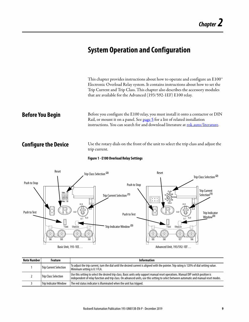
Configure the Device Use the rotary dials on the front of the unit to select the trip class and adjust the trip current.
Figure 1 - E100 Overload Relay Settings
Basic Unit, 193-1EE… Advanced Unit, 193/592-1EF…
Trip Current Selection (1)Trip Current Selection(1)
Trip Class Selection (2)
Trip Class Selection (2)Reset Reset
Push to Stop Push to Stop
Push to TestPush to Test
Trip Indicator Window (3)
Trip Indicator Window(3)
Note Number Feature Information
1 Trip Current Selection To adjust the trip current, turn the dial until the desired current is aligned with the pointer. Trip rating is 120% of dial setting value. Minimum setting is 0.1 FLA.
2 Trip Class Selection Use this setting to select the desired trip class. Basic units only support manual reset operations. Manual DIP switch position is independent of relay function and trip class. On advanced units, use this setting to select between automatic and manual reset modes.
3 Trip Indicator Window The red status indicator is illuminated when the unit has tripped.
Rockwell Automation Publication 193-UM013B-EN-P - December 2019 9
Chapter 2 System Operation and Configuration
Set the Trip Current
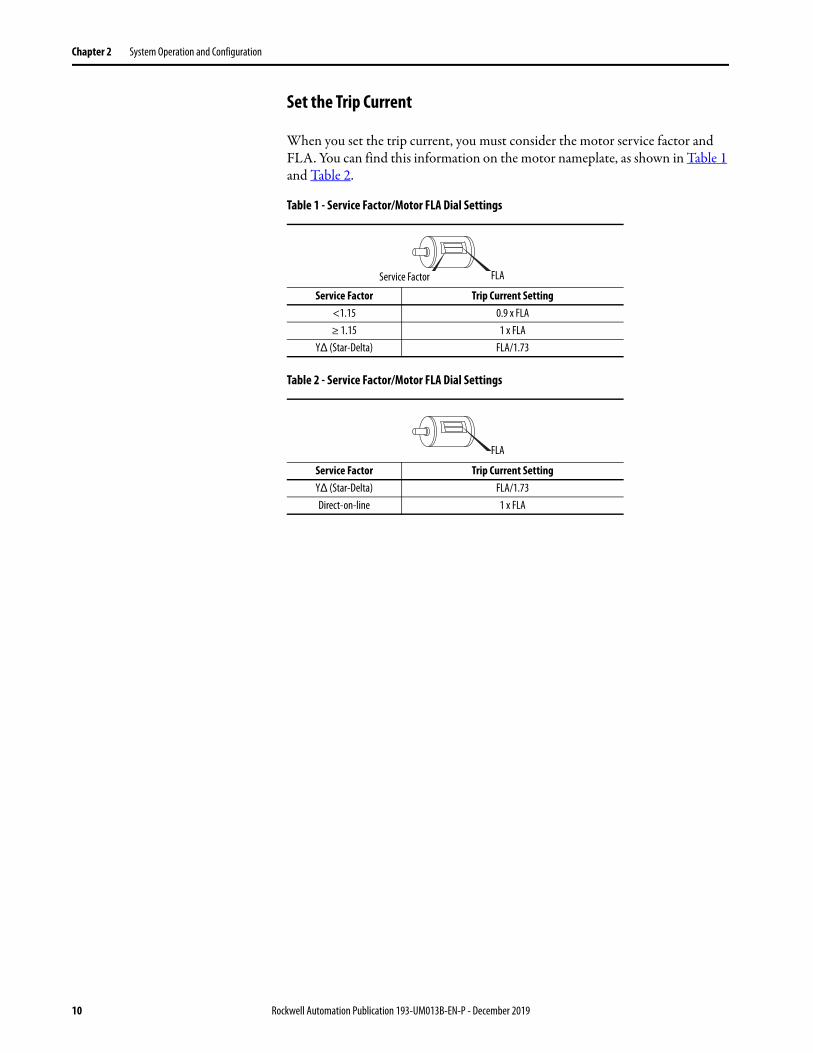
When you set the trip current, you must consider the motor service factor and FLA. You can find this information on the motor nameplate, as shown in Table 1 and Table 2.
Table 1 - Service Factor/Motor FLA Dial Settings
Table 2 - Service Factor/Motor FLA Dial Settings
Service Factor Trip Current Setting<1.15 0.9 x FLA≥ 1.15 1 x FLA
YΔ (Star-Delta) FLA/1.73
Service Factor Trip Current SettingYΔ (Star-Delta) FLA/1.73Direct-on-line 1 x FLA
Service Factor FLA
FLA
10 Rockwell Automation Publication 193-UM013B-EN-P - December 2019
System Operation and Configuration Chapter 2
Configure Accessory Modules
This section describes how to configure the accessory modules for the Advanced version (193/592-1EF) of the E100 relay. You must correctly install the accessories before you configure them. See page 5 for a list of related installation instructions.
Cat. No. 193-1EGJ Universal Protection Expansion Module
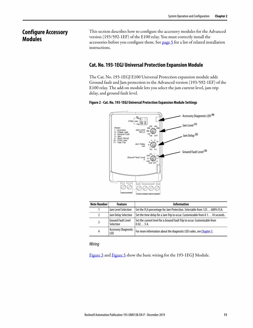
The Cat. No. 193-1EGJ E100 Universal Protection expansion module adds Ground fault and Jam protection to the Advanced version (193/592-1EF) of the E100 relay. The add-on module lets you select the jam current level, jam trip delay, and ground fault level.
Figure 2 - Cat. No. 193-1EGJ Universal Protection Expansion Module Settings
Wiring
Figure 3 and Figure 5 show the basic wiring for the 193-1EGJ Module.
Note Number Feature Information1 Jam Level Selection Set the FLA percentage for Jam Protection. Selectable from 125…600% FLA.2 Jam Delay Selection Set the time delay for a Jam Trip to occur. Customizable from 0.1…10 seconds.
3 Ground Fault Level Selection
Set the current level for a Ground Fault Trip to occur. Customizable from 0.02…5 A.
4 Accessory Diagnostic LED For more information about the diagnostic LED codes, see Chapter 3.
Jam Level (1)
Jam Delay (2)
Ground Fault Level (3)
Accessory Diagnostic LED (4)
Rockwell Automation Publication 193-UM013B-EN-P - December 2019 11

Chapter 2 System Operation and Configuration
Figure 3 - Cat. No. 193-1EGJ Universal Protection Expansion Module Wiring
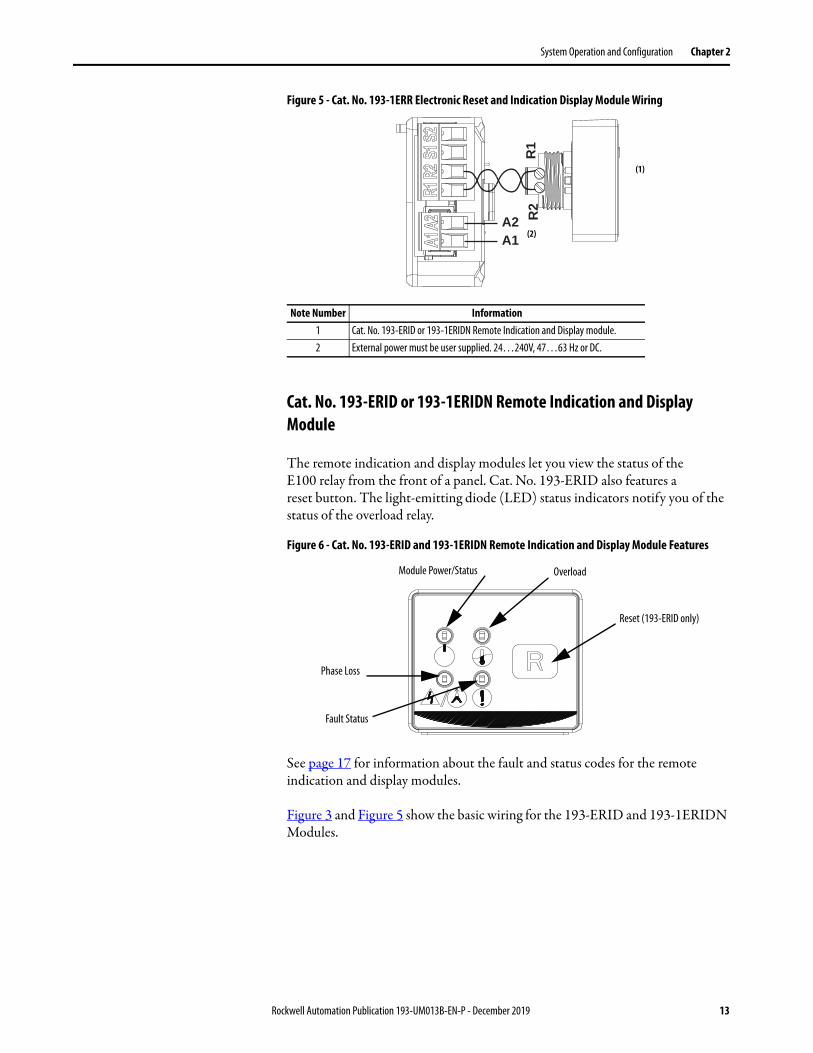
Cat. No. 193-1ERR Electronic Reset and Indication Display Module
The Cat. No. 193-1ERR Electronic Reset and Indication Display Module lets you use the Cat. No. 193-ERID and 193-ERIDN Remote Indication and Display module with your Advanced version (193/592-1EF) of the E100 relay.
Figure 4 - Cat. No. 193-1ERR Electronic Reset and Indication Display Module
Wiring
Figure 3 and Figure 5 show the basic wiring for the 193-1ERR Module.
Note Number Information1 Terminals R1 and R2 are used with 193-ERID and 193-1ERIDN modules.2 External power must be user supplied. 24…240V, 47…63 Hz or DC.3 Reserved for 193-CBCT external ground fault current sensor.
Note Number Feature Information1 Accessory Diagnostic LED For more information about the diagnostic LED codes, see Chapter 3.
R1
R2S1S2
A1A2
(1)
(2)
(3)
Accessory Diagnostic LED(1)
12 Rockwell Automation Publication 193-UM013B-EN-P - December 2019
System Operation and Configuration Chapter 2
Figure 5 - Cat. No. 193-1ERR Electronic Reset and Indication Display Module Wiring
Cat. No. 193-ERID or 193-1ERIDN Remote Indication and Display Module
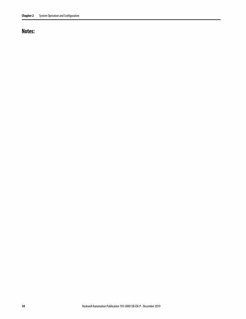
The remote indication and display modules let you view the status of the E100 relay from the front of a panel. Cat. No. 193-ERID also features a reset button. The light-emitting diode (LED) status indicators notify you of the status of the overload relay.
Figure 6 - Cat. No. 193-ERID and 193-1ERIDN Remote Indication and Display Module Features
See page 17 for information about the fault and status codes for the remote indication and display modules.
Figure 3 and Figure 5 show the basic wiring for the 193-ERID and 193-1ERIDN Modules.
Note Number Information1 Cat. No. 193-ERID or 193-1ERIDN Remote Indication and Display module.2 External power must be user supplied. 24…240V, 47…63 Hz or DC.
R2
R1
A1A2
(1)
(2)
Reset (193-ERID only)
Module Power/Status
Fault Status
Phase Loss
Overload
Rockwell Automation Publication 193-UM013B-EN-P - December 2019 13
Chapter 2 System Operation and Configuration
Notes:
14 Rockwell Automation Publication 193-UM013B-EN-P - December 2019
Chapter 3
Troubleshooting
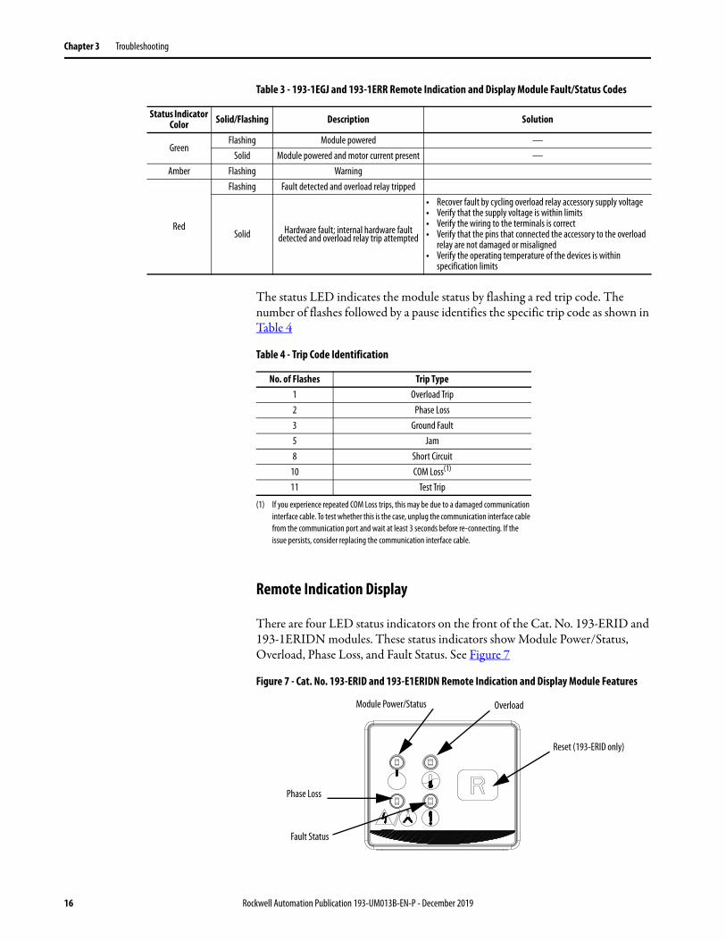
This chapter helps you troubleshoot the E100™ Electronic Overload Relay by using the diagnostic LED status indicators. It also guides you through troubleshooting associated accessory modules.
E100 Electronic Overload Relay
All E100 relay units include a trip indicator window on the front of the unit labeled “Status”. If the red indicator is not visible, the overload relay is not tripped. If the red indicator is visible, the overload relay is tripped.
Accessory Modules Universal Protection Module and Remote Reset Module
The Universal Protection Module and the Remote Reset Module both include an LED status indicator that shows the state of the E100 relay. The modules are supplied with external power, so in the event of a fault event, the status LEDs still operates.
ATTENTION: Servicing energized industrial control equipment can be hazardous. Electrical shock, burns, or unintentional actuation of controlled industrial equipment may cause death or serious injury. For safety of maintenance personnel and others who may be exposed to electrical hazards associated with the maintenance activities, follow the local safety-related work practices (for example, the NFPA 70E, Part II, Electrical Safety for Employee Workplaces, in the United States) when working on or near energized equipment. Maintenance personnel must be trained in the safety practices, procedures, and requirements that pertain to their respective job assignments. Do not work alone on energized equipment.
ATTENTION: Do not attempt to defeat or override fault circuits. The cause of a fault indication must be determined and corrected before attempting operation. Failure to correct a control system or mechanical malfunction may result in personal injury and/or equipment damage due to uncontrolled machine system operation.
Rockwell Automation Publication 193-UM013B-EN-P - December 2019 15
Chapter 3 Troubleshooting
Table 3 - 193-1EGJ and 193-1ERR Remote Indication and Display Module Fault/Status Codes
The status LED indicates the module status by flashing a red trip code. The number of flashes followed by a pause identifies the specific trip code as shown in Table 4
Table 4 - Trip Code Identification
Remote Indication Display
There are four LED status indicators on the front of the Cat. No. 193-ERID and 193-1ERIDN modules. These status indicators show Module Power/Status, Overload, Phase Loss, and Fault Status. See Figure 7
Figure 7 - Cat. No. 193-ERID and 193-E1ERIDN Remote Indication and Display Module Features
Status Indicator Color Solid/Flashing Description Solution
GreenFlashing Module powered —
Solid Module powered and motor current present —Amber Flashing Warning
Red
Flashing Fault detected and overload relay tripped
Solid Hardware fault; internal hardware fault detected and overload relay trip attempted
• Recover fault by cycling overload relay accessory supply voltage• Verify that the supply voltage is within limits• Verify the wiring to the terminals is correct• Verify that the pins that connected the accessory to the overload
relay are not damaged or misaligned• Verify the operating temperature of the devices is within
specification limits
No. of Flashes Trip Type1 Overload Trip2 Phase Loss3 Ground Fault5 Jam8 Short Circuit
10 COM Loss(1)
(1) If you experience repeated COM Loss trips, this may be due to a damaged communication interface cable. To test whether this is the case, unplug the communication interface cable from the communication port and wait at least 3 seconds before re-connecting. If the issue persists, consider replacing the communication interface cable.
11 Test Trip
Reset (193-ERID only)
Module Power/Status
Fault Status
Phase Loss
Overload
16 Rockwell Automation Publication 193-UM013B-EN-P - December 2019
Troubleshooting Chapter 3
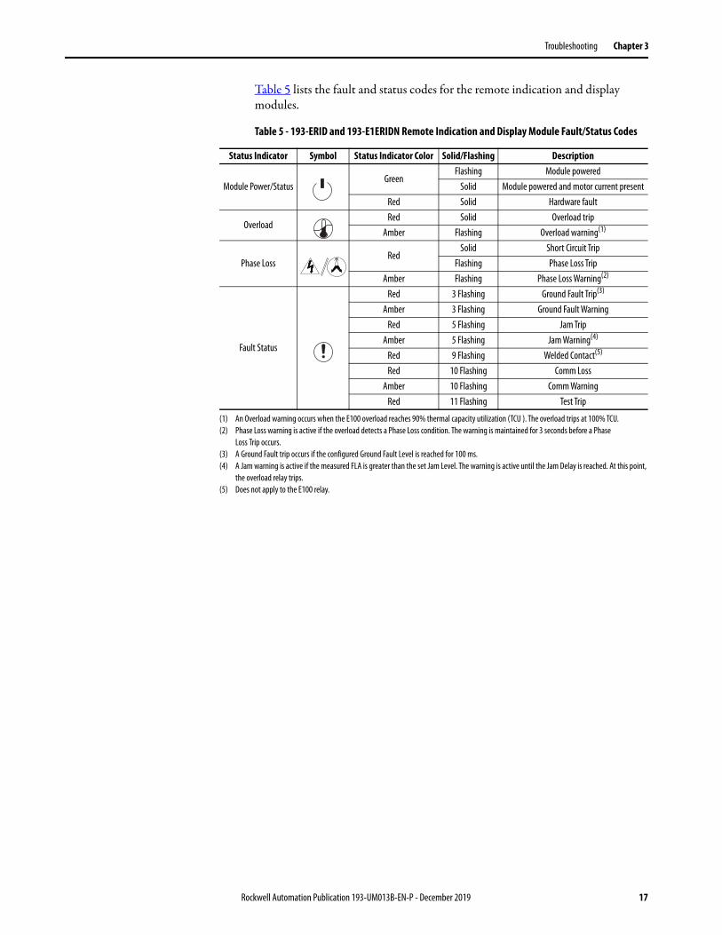
Table 5 lists the fault and status codes for the remote indication and display modules.
Table 5 - 193-ERID and 193-E1ERIDN Remote Indication and Display Module Fault/Status Codes
Status Indicator Symbol Status Indicator Color Solid/Flashing Description
Module Power/StatusGreen
Flashing Module poweredSolid Module powered and motor current present
Red Solid Hardware fault
OverloadRed Solid Overload trip
Amber Flashing Overload warning(1)
Phase LossRed
Solid Short Circuit TripFlashing Phase Loss Trip
Amber Flashing Phase Loss Warning(2)
Fault Status
Red 3 Flashing Ground Fault Trip(3)
Amber 3 Flashing Ground Fault WarningRed 5 Flashing Jam Trip
Amber 5 Flashing Jam Warning(4)
Red 9 Flashing Welded Contact(5)
Red 10 Flashing Comm LossAmber 10 Flashing Comm Warning
Red 11 Flashing Test Trip
(1) An Overload warning occurs when the E100 overload reaches 90% thermal capacity utilization (TCU ). The overload trips at 100% TCU.(2) Phase Loss warning is active if the overload detects a Phase Loss condition. The warning is maintained for 3 seconds before a Phase
Loss Trip occurs.(3) A Ground Fault trip occurs if the configured Ground Fault Level is reached for 100 ms.(4) A Jam warning is active if the measured FLA is greater than the set Jam Level. The warning is active until the Jam Delay is reached. At this point,
the overload relay trips.(5) Does not apply to the E100 relay.
Rockwell Automation Publication 193-UM013B-EN-P - December 2019 17
Chapter 3 Troubleshooting
Notes:
18 Rockwell Automation Publication 193-UM013B-EN-P - December 2019
Appendix A
Wiring Diagrams
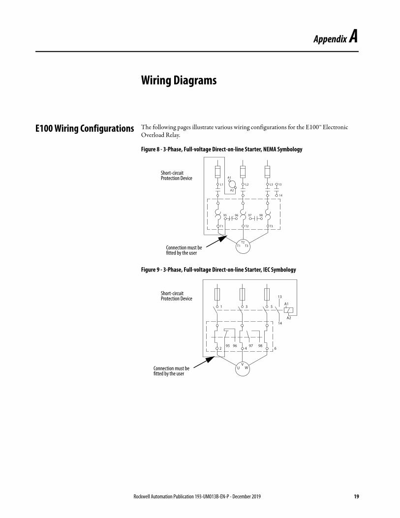
E100 Wiring Configurations The following pages illustrate various wiring configurations for the E100™ Electronic Overload Relay.
Figure 8 - 3-Phase, Full-voltage Direct-on-line Starter, NEMA Symbology
Figure 9 - 3-Phase, Full-voltage Direct-on-line Starter, IEC Symbology
95
L2 L3 13L1
14
A1
A2
T2 T3T1
96 97 98
T1 T3T2
Connection must be fitted by the user
Short-circuit Protection Device
95
3
13
1
14
A1
A2
4 6296
UV
5
97 98
WConnection must be fitted by the user
Short-circuit Protection Device
Rockwell Automation Publication 193-UM013B-EN-P - December 2019 19
Appendix A Wiring Diagrams
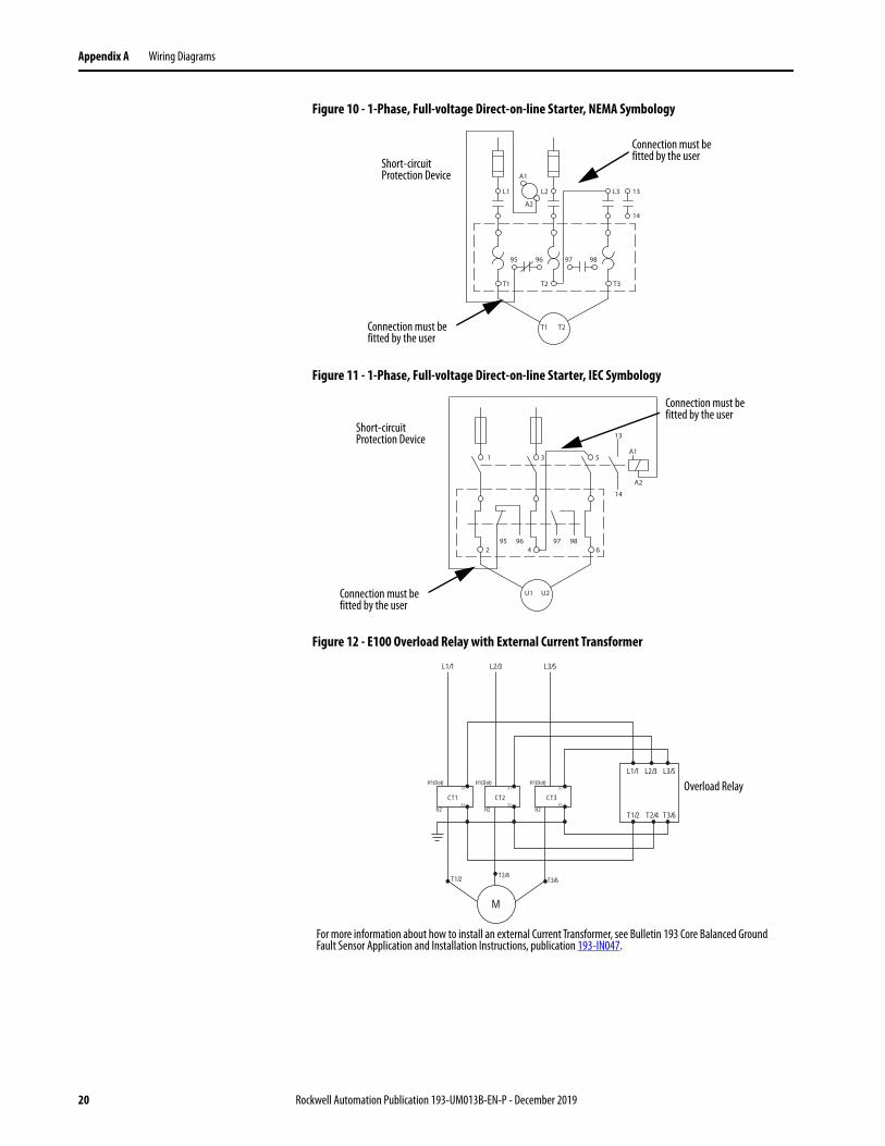
Figure 10 - 1-Phase, Full-voltage Direct-on-line Starter, NEMA Symbology
Figure 11 - 1-Phase, Full-voltage Direct-on-line Starter, IEC Symbology
Figure 12 - E100 Overload Relay with External Current Transformer
95
L2 L3 13L1
14
A1
A2
T2 T3T1
96 97 98
T1 T2Connection must be fitted by the user
Short-circuit Protection Device
Connection must be fitted by the user
95
3 5
13
1
14
A1
A2
4 6296 97 98
U1 U2Connection must be fitted by the user
Short-circuit Protection Device
Connection must be fitted by the user
M
L1/1
L1/1
T1/2 T2/4 T3/6
L2/3 L3/5
L2/3 L3/5
H1(Dot) H1(Dot) H1(Dot)
H2 H2 H2
X1 X1 X1
X2X2X2CT1
T1/2 T2/4T3/6
CT2 CT3Overload Relay
For more information about how to install an external Current Transformer, see Bulletin 193 Core Balanced Ground Fault Sensor Application and Installation Instructions, publication 193-IN047.
20 Rockwell Automation Publication 193-UM013B-EN-P - December 2019

Notes:
Publication 193-UM013B-EN-P - December 2019Supersedes publication 193-UM013A-EN-P November 2019 Copyright © 2019 Rockwell Automation, Inc. All rights reserved. Printed in the U.S.A.
Rockwell Automation SupportUse the following resources to access support information.
Documentation FeedbackYour comments will help us serve your documentation needs better. If you have any suggestions on how to improve this document, complete the How Are We Doing? form at rok.auto/docfeedback.
Technical Support Center Knowledgebase Articles, How-to Videos, FAQs, Chat, User Forums, and Product Notification Updates. rok.auto/support
Knowledgebase Knowledgebase Articles rok.auto/knowledgebase
Local Technical Support Phone Numbers Locate the phone number for your country. rok.auto/phonesupport
Literature Library Installation Instructions, Manuals, Brochures, and Technical Data. rok.auto/literature
Product Compatibility and Download Center (PCDC)
Get help determining how products interact, check features and capabilities, and find associated firmware. rok.auto/pcdc
Rockwell Otomasyon Ticaret A.Ş., Kar Plaza İş Merkezi E Blok Kat:6 34752 İçerenköy, İstanbul, Tel: +90 (216) 5698400
Rockwell Automation maintains current product environmental information on its website at rok.auto/pec.
Allen-Bradley, E100, Rockwell Automation, and Rockwell Software are trademarks of Rockwell Automation, Inc.
Trademarks not belonging to Rockwell Automation are property of their respective companies.