Embed Size (px)
Citation preview

E300 Electronic Overload RelayBulletin Numbers 193, 592
Selection Guide

2 Rockwell Automation Publication 193-SG010C-EN-P - November 2014
E300 Electronic Overload Relay
What’s Inside
Topic Page
Bulletin 193/592-E300 Overview 3
Bulletin 193/592-E300 Product Selection 11
Sensing Modules 11
Control, Communication, and Expansion Modules 12
Accessories 12
Bulletin 193/592-E300 Specifications 13
Bulletin 193/592-E300 Approximate Dimensions 21

Rockwell Automation Publication 193-SG010C-EN-P - November 2014 3
Overview
Bulletin 193/592-E300 Overview
The E300 Electronic Overload Relay is the newest technology for overload protection. Its modular design, communication
options, diagnostic information, simplified wiring, and integration into Logix make this the ideal overload for motor control
applications in an automation system.
E300 Electronic Overload Relays provide the following benefits:
• Intelligent motor control (EtherNet/IP enabled)
• Scalable solution
• Diagnostic Information
• Integrated I/O
• Adjustable trip class 5…30
• Wide current range
• Test/Reset button
• Programmable trip and warning settings
• True RMS current/voltage sensing (50/60 Hz)
• Protection for single- and three-phase motors
NOTE: Your order must include 1) the Cat. No. of the sensing module, control module, and communication module selected,
and 2)if required, Cat. No. of any accessories.
Standards Compliance and Certifications
Product Overview
The E300 consists of three modules: sensing, control and communications. Users have choices in each of the three with
additional accessories to tailor the electronic overload for their application’s exact needs.
Sensing Module
Sensing Options
• Voltage/current/ground fault
• Current/ground fault
• Current
Standards Compliance Certifications
EN 60947-1 CE Marked
UL508 CCC
UL1053 (class 1) CSA Certified
CSA22.2, No. 14 UL Listed
4 Rockwell Automation Publication 193-SG010C-EN-P - November 2014
Overview
Current Range [A]
• 0.5…30
• 6…60
• 10…100
Control Module
Communication Module • EtherNet/IP
Expansion Digital I/O
Users can add up to four additional expansion digital modules to the E300 expansion bus.
• 4 inputs/2 relay outputs
• 24V DC
• 120V AC
• 240V AC
Expansion Analog I/O
Users can add up to four additional expansion analog modules to the E300 expansion bus.
• 3 universal analog inputs/1 analog output
• 0…10V
• 0…5V
• 1…5V
• 0…20 mA
• 4…20 mA
• RTD (2-wire or 3-wire)
• 0…150
• 0…750
• 0…3000
• 0…6000 (PTC/NTC)
Expansion Power Supply
When more than one expansion digital module and one operator station are added to the E300 expansion bus, an expansion
power supply is needed to supplement power for the additional modules. One expansion power supply will power a fully
loaded E300 expansion bus.
• 120/240V AC
• 24V DC
Control VoltageI/O
Inputs Relay Outputs
110…120V AC, 50/60 Hz 4 3
220…240V AC, 50/60 Hz 4 3
24V DC 6 3
Rockwell Automation Publication 193-SG010C-EN-P - November 2014 5
Overview
Expansion Operator Station
One operator station can be added to the E300 expansion bus to be used as a user interface device. The operator stations
provide E300 status LEDs and function keys for motor control. The operator stations also support CopyCat™, which allows user
to upload and download E300 configuration parameters.
• Control station
• Diagnostic station
Thermal Overload
Thermal Utilization
The E300 Electronic Overload Relay provides overload protection through true RMS current measurement of the individual
phase currents of the connected motor. Based on this information, a thermal model that simulates the actual heating of the
motor is calculated. Percent of thermal capacity utilization (%TCU) reports this calculated value and can be read via a
communications network. An overload trip occurs when the value reaches 100%.
Adjustable Settings
Thermal overload protection setup is accomplished simply by programming the motor’s full load current (FLC) rating and the
desired trip class (5…30). Programming of the actual values through software programming ensures the accuracy of the
protection.
Thermal Memory
The E300 Electronic Overload Relay includes a thermal memory circuit designed to approximate the thermal decay for a trip
class 20 setting. This means that the thermal model of the connected motor is maintained at all times, even if the supply power
is removed.
Reset Modes
This flexibility allows the end-user in the ability to select between manual and automatic reset for an overload trip, allowing for
broad application. The point of reset is user adjustable from 1…100% TCU.
Time to Trip
During an overload condition, the E300 Electronic Overload Relay provides an estimated time to trip that is accessible via a
communications network. This allows corrective action to be taken so that production may continue uninterrupted.
Time to Reset
Following an overload trip, the E300 Electronic Overload Relay will not reset until the calculated percentage of thermal capacity
utilization falls below the reset level. As this value decays, the time to reset, which is accessible via a communications network, is
reported.
Thermal Warning
The E300 Electronic Overload Relay provides the capability to alert in the event of an impending overload trip. A thermal
warning bit is set in the Current Warning Status when the calculated percentage of thermal capacity utilization exceeds the
programmed thermal warning level, which has a setting range of 0…100% TCU.
6 Rockwell Automation Publication 193-SG010C-EN-P - November 2014
Overview
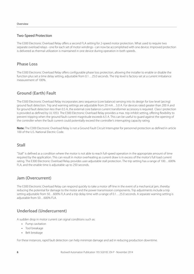
Two-Speed Protection
The E300 Electronic Overload Relay offers a second FLA setting for 2-speed motor protection. What used to require two
separate overload relays - one for each set of motor windings - can now be accomplished with one device. Improved protection
is delivered as thermal utilization is maintained in one device during operation in both speeds.
Phase Loss
The E300 Electronic Overload Relay offers configurable phase loss protection, allowing the installer to enable or disable the
function plus set a time delay setting, adjustable from 0.1…25.0 seconds. The trip level is factory-set at a current imbalance
measurement of 100%.
Ground (Earth) Fault
The E300 Electronic Overload Relay incorporates zero sequence (core balance) sensing into its design for low level (arcing)
ground fault detection. Trip and warning settings are adjustable from 20 mA…5.0 A. For devices rated greater than 200 A and
for ground fault detection less than 0.5 A, the external core balance current transformer accessory is required. Class I protection
is provided as defined by UL1053. The E300 Electronic Overload Relay provides a max. trip-inhibit setting, offering flexibility to
prevent tripping when the ground fault current magnitude exceeds 6.5 A. This can be useful to guard against the opening of
the controller when the fault current could potentially exceed the controller's interrupting capacity rating.
Note: The E300 Electronic Overload Relay is not a Ground Fault Circuit Interrupter for personnel protection as defined in article
100 of the U.S. National Electric Code.
Stall
"Stall" is defined as a condition where the motor is not able to reach full-speed operation in the appropriate amount of time
required by the application. This can result in motor overheating as current draw is in excess of the motor’s full load current
rating. The E300 Electronic Overload Relay provides user-adjustable stall protection. The trip setting has a range of 100…600%
FLA, and the enable time is adjustable up to 250 seconds.
Jam (Overcurrent)
The E300 Electronic Overload Relay can respond quickly to take a motor off-line in the event of a mechanical jam, thereby
reducing the potential for damage to the motor and the power transmission components. Trip adjustments include a trip
setting adjustable from 50…600% FLA and a trip delay time with a range of 0.1…25.0 seconds. A separate warning setting is
adjustable from 50…600% FLA.
Underload (Undercurrent)
A sudden drop in motor current can signal conditions such as:
• Pump cavitation
• Tool breakage
• Belt breakage
For these instances, rapid fault detection can help minimize damage and aid in reducing production downtime.
Rockwell Automation Publication 193-SG010C-EN-P - November 2014 7
Overview
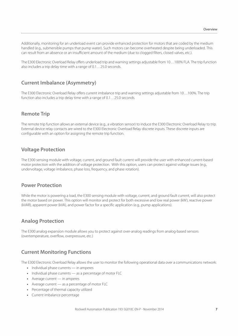
Additionally, monitoring for an underload event can provide enhanced protection for motors that are coded by the medium
handled (e.g., submersible pumps that pump water). Such motors can become overheated despite being underloaded. This
can result from an absence or an insufficient amount of the medium (due to clogged filters, closed valves, etc.).
The E300 Electronic Overload Relay offers underload trip and warning settings adjustable from 10…100% FLA. The trip function
also includes a trip delay time with a range of 0.1…25.0 seconds.
Current Imbalance (Asymmetry)
The E300 Electronic Overload Relay offers current imbalance trip and warning settings adjustable from 10…100%. The trip
function also includes a trip delay time with a range of 0.1…25.0 seconds.
Remote Trip
The remote trip function allows an external device (e.g., a vibration sensor) to induce the E300 Electronic Overload Relay to trip.
External device relay contacts are wired to the E300 Electronic Overload Relay discrete inputs. These discrete inputs are
configurable with an option for assigning the remote trip function.
Voltage Protection
The E300 sensing module with voltage, current, and ground fault current will provide the user with enhanced current-based
motor protection with the addition of voltage protection. With this option, users can protect against voltage issues (e.g.,
undervoltage, voltage imbalance, phase loss, frequency, and phase rotation).
Power Protection
While the motor is powering a load, the E300 sensing module with voltage, current, and ground fault current, will also protect
the motor based on power. This option will monitor and protect for both excessive and low real power (kW), reactive power
(kVAR), apparent power (kVA), and power factor for a specific application (e.g., pump applications).
Analog Protection
The E300 analog expansion module allows you to protect against over-analog readings from analog-based sensors
(overtemperature, overflow, overpressure, etc.)
Current Monitoring Functions
The E300 Electronic Overload Relay allows the user to monitor the following operational data over a communications network:
• Individual phase currents — in amperes
• Individual phase currents — as a percentage of motor FLC
• Average current — in amperes
• Average current — as a percentage of motor FLC
• Percentage of thermal capacity utilized
• Current imbalance percentage

8 Rockwell Automation Publication 193-SG010C-EN-P - November 2014
Overview
• Ground fault current
Voltage, Power, and Energy Monitoring
The E300 sensing module with voltage, current, and ground fault current can be included in a company’s energy management
system. This option will provide voltage, current, power (kW, kVAR, and kVA), energy (kWh, kVARh, kVAh, kW Demand, kVAR
Demand, and kVA Demand), and power quality (power factor, frequency, and phase rotation) information down at the motor
level.
Diagnostic Functions
The E300 Electronic Overload Relay allows the user to monitor the following diagnostic information over a communications
network:
Status Indicators
The E300 Electronic Overload Relay provides the following LED indicators:
• Power — This green/red LED indicates the status of the overload relay.
• TRIP/WARN — This LED flashes a yellow code under a warning condition and a red code when tripped.
Inputs/Outputs
Inputs allow the connection of such devices as contactor and disconnect auxiliary contacts, pilot devices, limit switches, and
float switches. Input status can be monitored via the network and mapped to a controller’s input image table. Inputs are rated
24V DC, 120V AC, or 240V AC and are current sinking. Power for the inputs is sourced separately with convenient customer
sources at terminal A1. Relay contact outputs can be controlled via the network or DeviceLogix function blocks for performing
such tasks as contactor operation.
Test/Reset Button
The Test/Reset button, located on the front of the E300 Electronic Overload Relay, allows the user to perform the following:
• Test — The trip relay contact will open if the E300 Electronic Overload Relay is in an untripped condition and the Test/
Reset button is pressed for 2 seconds or longer.
• Reset — The trip relay contact will close if the E300 Electronic Overload Relay is in a tripped condition, supply voltage is
present, and the Test/Reset button is pressed.
• Device status • History of past five trips
• Trip status • History of past five warnings
• Warning status • Hours of operation
• Time to an overload trip • Number of starts
• Time to reset after an overload • Trip snapshot trip

Rockwell Automation Publication 193-SG010C-EN-P - November 2014 9
Overview
Single/Three-Phase Operation
The E300 Electronic Overload Relay can be applied to three-phase as well as single-phase applications. A programming
parameter is provided for selection between single- and three-phase operation. Straight-through wiring is afforded in both
cases.
EtherNet/IP Communications
The E300 EtherNet/IP communication module has two RJ45 ports that act as an Ethernet switch to support a star, linear, and
ring topology and supports the following:
• 2 concurrent Class 1 connections [1 exclusive owner + (1 input only or 1 listen only)]
• 6 simultaneous Class 3 connections (explicit messaging)
• Embedded web server
• SMTP server for trip and warning events (email and text messaging)
• Embedded EDS file
• RSLogix 5000 add-on profile
For more information on operation and maintenance of this product, please reference the user manual,
publication 193-UM015.

10 Rockwell Automation Publication 193-SG010C-EN-P - November 2014
Overview
Notes:
Rockwell Automation Publication 193-SG010C-EN-P - November 2014 11
Product Selection
Bulletin 193/592-E300 Product Selection
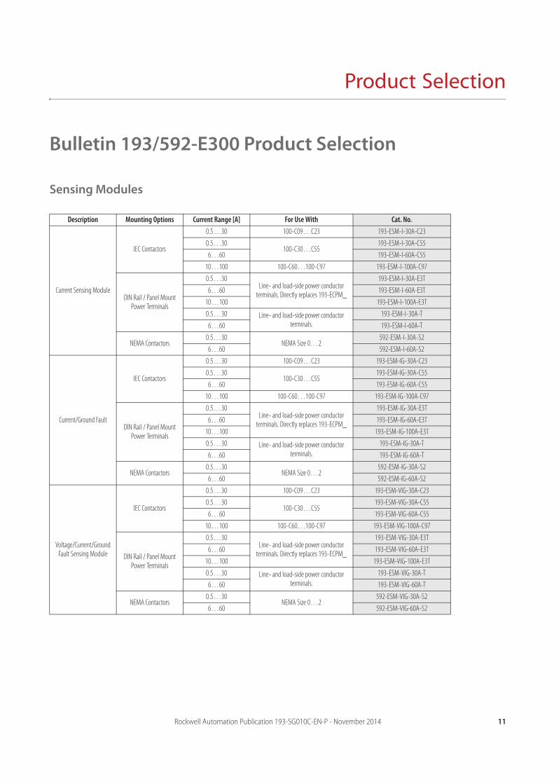
Sensing Modules
Description Mounting Options Current Range [A] For Use With Cat. No.
Current Sensing Module
IEC Contactors
0.5…30 100-C09…C23 193-ESM-I-30A-C23
0.5…30100-C30…C55
193-ESM-I-30A-C55
6…60 193-ESM-I-60A-C55
10…100 100-C60…100-C97 193-ESM-I-100A-C97
DIN Rail / Panel Mount Power Terminals
0.5…30Line- and load-side power conductor
terminals. Directly replaces 193-ECPM_
193-ESM-I-30A-E3T
6…60 193-ESM-I-60A-E3T
10…100 193-ESM-I-100A-E3T
0.5…30 Line- and load-side power conductor terminals.
193-ESM-I-30A-T
6…60 193-ESM-I-60A-T
NEMA Contactors0.5…30
NEMA Size 0…2592-ESM-I-30A-S2
6…60 592-ESM-I-60A-S2
Current/Ground Fault
IEC Contactors
0.5…30 100-C09…C23 193-ESM-IG-30A-C23
0.5…30100-C30…C55
193-ESM-IG-30A-C55
6…60 193-ESM-IG-60A-C55
10…100 100-C60…100-C97 193-ESM-IG-100A-C97
DIN Rail / Panel Mount Power Terminals
0.5…30Line- and load-side power conductor
terminals. Directly replaces 193-ECPM_
193-ESM-IG-30A-E3T
6…60 193-ESM-IG-60A-E3T
10…100 193-ESM-IG-100A-E3T
0.5…30 Line- and load-side power conductor terminals.
193-ESM-IG-30A-T
6…60 193-ESM-IG-60A-T
NEMA Contactors0.5…30
NEMA Size 0…2592-ESM-IG-30A-S2
6…60 592-ESM-IG-60A-S2
Voltage/Current/Ground Fault Sensing Module
IEC Contactors
0.5…30 100-C09…C23 193-ESM-VIG-30A-C23
0.5…30100-C30…C55
193-ESM-VIG-30A-C55
6…60 193-ESM-VIG-60A-C55
10…100 100-C60…100-C97 193-ESM-VIG-100A-C97
DIN Rail / Panel Mount Power Terminals
0.5…30Line- and load-side power conductor
terminals. Directly replaces 193-ECPM_
193-ESM-VIG-30A-E3T
6…60 193-ESM-VIG-60A-E3T
10…100 193-ESM-VIG-100A-E3T
0.5…30 Line- and load-side power conductor terminals.
193-ESM-VIG-30A-T
6…60 193-ESM-VIG-60A-T
NEMA Contactors0.5…30
NEMA Size 0…2592-ESM-VIG-30A-S2
6…60 592-ESM-VIG-60A-S2
12 Rockwell Automation Publication 193-SG010C-EN-P - November 2014
Product Selection
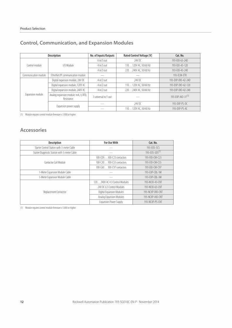
Control, Communication, and Expansion Modules
Accessories
Description No. of Inputs/Outputs Rated Control Voltage [V] Cat. No.
Control module I/O Module
6 in/3 out 24V DC 193-EIO-63-24D
4 in/3 out 110…120V AC, 50/60 Hz 193-EIO-43-120
4 in/3 out 220…240V AC, 50/60 Hz 193-EIO-43-240
Communication module EtherNet/IP communication module — — 193-ECM-ETR
Expansion module
Digital expansion module, 24V DC 4 in/2 out 24V DC 193-EXP-DIO-42-24D
Digital expansion module, 120V AC 4 in/2 out 110…120V AC, 50/60 Hz 193-EXP-DIO-42-120
Digital expansion module, 240V AC 4 in/2 out 220…240V AC, 50/60 Hz 193-EXP-DIO-42-240
Analog expansion module: mA, V, RTD, Resistance
3 universal in/1 out — 193-EXP-AIO-31(1)
(1) Module requires control module firmware v 3.000 or higher.
Expansion power supply— 24V DC 193-EXP-PS-DC
— 110…120V AC, 50/60 Hz 193-EXP-PS-AC
Description For Use With Cat. No.Starter Control Station with 3-meter Cable — 193-EOS-SCS
Starter Diagnostic Station with 3-meter Cable — 193-EOS-SDS(1)
(1) Module requires control module firmware v 3.000 or higher.
Contactor Coil Module
100-C09…100-C23 contactors 193-EIO-CM-C23
100-C30…100-C55 contactors 193-EIO-CM-C55
100-C60…100-C97 contactors 193-EIO-CM-C97
1-Meter Expansion Module Cable — 193-EXP-CBL-1M
3-Meter Expansion Module Cable — 193-EXP-CBL-3M
Replacement Connector
120…240V AC 4:3 Control Modules 193-NCIO-43-CNT
24V DC 6:3 Control Modules 193-NCIO-63-CNT
Digital Expansion Modules 193-NCXP-DIO-CNT
Analog Expansion Modules 193-NCXP-AIO-CNT
Expansion Power Supply 193-NCXP-PS-CNT
Rockwell Automation Publication 193-SG010C-EN-P - November 2014 13
Specifications
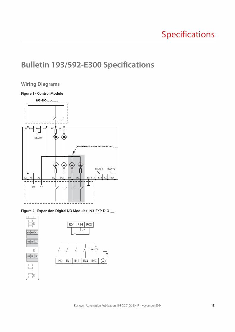
Bulletin 193/592-E300 Specifications
Wiring Diagrams
Figure 1 - Control Module
Figure 2 - Expansion Digital I/O Modules 193-EXP-DIO-__
R24R23
RELAY 2RELAY 1
R14R13IN3IN2
Additional Inputs for 193-EIO-63-_ _ _
IN0 IN1
A2 PEA1A1
A1 R03 R04 A2
IN5IN4
(+) (-)
RELAY 0
193-EIO-_ _-_ _ _
R04 R14 RC3
IN0 INCIN1 IN2 IN3
Source+
-IN0 IN1 INC
IN2 IN3
RS2R04 R14 RC3
14 Rockwell Automation Publication 193-SG010C-EN-P - November 2014
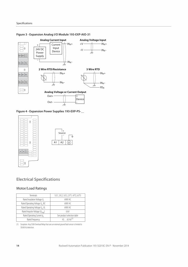
Specifications
Figure 3 - Expansion Analog I/O Module 193-EXP-AIO-31
Figure 4 - Expansion Power Supplies 193-EXP-PS-__
Electrical Specifications
Motor/Load Ratings
Terminals 1/L1, 3/L2, 5/L3, 2/T1, 4/T2, 6/T3
Rated Insulation Voltage Ui 690V AC
Rated Operating Voltage Ue, IEC 690V AC
Rated Operating Voltage Ue, UL 690V AC
Rated Impulse Voltage (Uimp) 6 kV
Rated Operating Current Ie See product selection table
Rated Frequency 45…65 Hz(1)
(1) Exception: Any E300 Overload Relay that uses an external ground fault sensor is limited to
50/60 Hz detection.
Analog Current Input Analog Voltage Input
24V DCPowerSupply
INx+
INx-
+
-
CurrentInput
Device
INx+
-V
+V
INx-
Analog Voltage or Current Output
+
Out-
Out+Device-
2 Wire RTD/Resistance
INx+
INx- INx-
3 Wire RTD
INx+
RSx
IN1+ IN1- RS1
IN2+ IN2- RS2
OUT+OUT-
IN0+ IN0- RS0
A1 A2
Source+
-
A1 A2
Rockwell Automation Publication 193-SG010C-EN-P - November 2014 15
Specifications
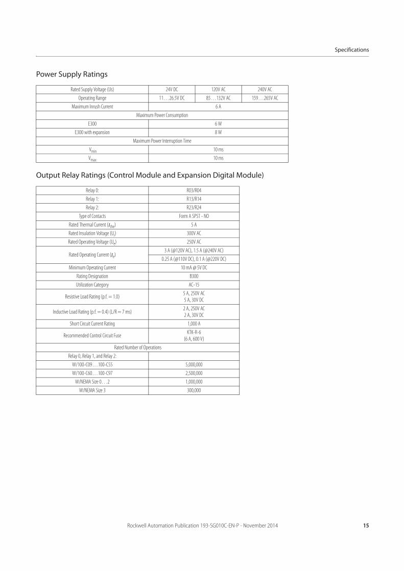
Power Supply Ratings
Output Relay Ratings (Control Module and Expansion Digital Module)
Rated Supply Voltage (Us) 24V DC 120V AC 240V AC
Operating Range 11…26.5V DC 85…132V AC 159…265V AC
Maximum Inrush Current 6 A
Maximum Power Consumption
E300 6 W
E300 with expansion 8 W
Maximum Power Interruption Time
Vmin 10 ms
Vmax 10 ms
Relay 0: R03/R04
Relay 1: R13/R14
Relay 2: R23/R24
Type of Contacts Form A SPST - NO
Rated Thermal Current (Ithe) 5 A
Rated Insulation Voltage (Ui) 300V AC
Rated Operating Voltage (Ue) 250V AC
Rated Operating Current (Ie)3 A (@120V AC), 1.5 A (@240V AC)
0.25 A (@110V DC), 0.1 A (@220V DC)
Minimum Operating Current 10 mA @ 5V DC
Rating Designation B300
Utilization Category AC-15
Resistive Load Rating (p.f. = 1.0)5 A, 250V AC5 A, 30V DC
Inductive Load Rating (p.f. = 0.4) (L/R = 7 ms)2 A, 250V AC2 A, 30V DC
Short Circuit Current Rating 1,000 A
Recommended Control Circuit FuseKTK-R-6
(6 A, 600 V)
Rated Number of Operations
Relay 0, Relay 1, and Relay 2:
W/100-C09…100-C55 5,000,000
W/100-C60…100-C97 2,500,000
W/NEMA Size 0…2 1,000,000
W/NEMA Size 3 300,000
16 Rockwell Automation Publication 193-SG010C-EN-P - November 2014
Specifications
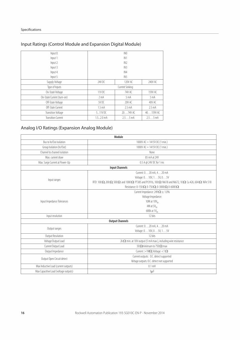
Input Ratings (Control Module and Expansion Digital Module)
Analog I/O Ratings (Expansion Analog Module)
Input 0:
Input 1:
Input 2:
Input 3:
Input 4:
Input 5:
IN0
IN1
IN2
IN3
IN4
IN5
Supply Voltage 24V DC 120V AC 240V AC
Type of Inputs Current Sinking
On-State Voltage 11V DC 74V AC 159V AC
On-State Current (turn-on) 2 mA 5 mA 5 mA
Off-State Voltage 5V DC 20V AC 40V AC
Off-State Current 1.5 mA 2.5 mA 2.5 mA
Transition Voltage 5...11V DC 20…74V AC 40…159V AC
Transition Current 1.5...2.0 mA 2.5…5 mA 2.5…5 mA
ModuleBus to In/Out isolation 1000V AC = 1415V DC (1 min.)
Group Isolation (In/Out) 1000V AC = 1415V DC (1 min.)
Channel to channel isolation None
Max. current draw 85 mA at 24V
Max. Surge Current at Power-Up 0.5 A @ 24V DC for 1 ms
Input Channels
Input ranges
Current: 0…20 mA, 4…20 mA
Voltage: 0…10V, 1…5V, 0…5V
RTD: 100 , 200 , 500 and 1000 PT385 and Pt3916, 100 Ni618 and Ni672, 10 Cu 426, 604 NiFe 518
Resistance: 0-150 , 0-750 , 0-3000 , 0-6000
Input Impedance Tolerances
Current Impedance: 249 ± 1.0%
Voltage Impedance:
10M at 10Vin
4M at 5Vin
680k at 1Vin
Input resolution 12 bits
Output Channels
Output rangesCurrent: 0…20 mA, 4…20 mA
Voltage: 0…10V, 0…5V, 1…5V
Output Resolution 12 bits
Voltage Output Load 2k min. at 10V output (5 mA max.), including wire resistance
Current Output Load 50 minimum to 750 max
Output Impedance Current: >1M , Voltage: <1
Output Open Circuit detectCurrent outputs: O.C. detect supported
Voltage outputs: O.C. detect not supported
Max Inductive Load (current outputs) 0.1 mH
Max Capacitive Load (voltage outputs) 1 F
Rockwell Automation Publication 193-SG010C-EN-P - November 2014 17
Specifications
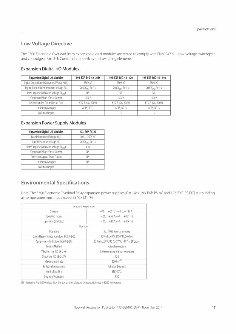
Low Voltage Directive
The E300 Electronic Overload Relay expansion digital modules are tested to comply with EN60947-5-1 Low-voltage switchgear
and controlgear Part 5-1: Control circuit devices and switching elements.
Expansion Digital I/O Modules
Expansion Power Supply Modules
Environmental Specifications
Note: The E300 Electronic Overload Relay expansion power supplies (Cat. Nos. 193-EXP-PS-AC and 193-EXP-PS-DC) surrounding
air temperature must not exceed 55 °C (131 °F).
Expansion Digital I/O Modules 193-EXP-DIO-42- 24D 193-EXP-DIO-42- 120 193-EXP-DIO-42- 240Digital Output Rated Operational Voltage (Ue) 250V AC 250V AC 250V AC
Digital Output Rated Insulation Voltage (Ui) 2000Vrms for 1 s 2000Vrms for 1 s 2000Vrms for 1 s
Rated Impulse Withstand Voltage (Uimp) NA NA NA
Conditional Short-Circuit Current 1000 A 1000 A 1000 A
Recommended Control Circuit Fuse KTK-R (6 A, 600V) KTK-R (6 A, 600V) KTK-R (6 A, 600V)
Utilization Category AC15, DC13 AC15, DC13 AC15, DC13
Pollution Degree 3 3 3
Expansion Digital I/O Modules 193-EXP-PS-ACRated Operational Voltage (Ue) 100…250V AC
Rated Insulation Voltage (Ui) 2640Vrms for 1 s
Rated Impulse Withstand Voltage (Uimp) 4 kV
Conditional Short-Circuit Current NA
Protection against Short Circuits NA
Utilization Category NA
Pollution Degree 3
Ambient Temperature
Storage –40…+85 °C (–40…+185 °F)
Operating (open) –20…+55 °C (–4…+131 °F)
Operating (enclosed) –20…+40 °C (–4…+104 °F)
Humidity
Operating 5…95% Non-condensing
Damp Heat – Steady State (per IEC 68-2-3) 92% r.h., 40 °C (104 °F), 56 days
Damp Heat – Cyclic (per IEC 68-2-30) 93% r.h., 25 °C/40 °C (77 °F/104 °F), 21 Cycles
Cooling Method Natural convection
Vibration (per IEC 68-2-6) 2.5 G operating, 5 G non-operating
Shock (per IEC 68-2-27) 30 G
Maximum Altitude 2000 m(1)
(1) Exception: Any E300 Overload Relay that uses an external ground fault sensor is limited to 50/60 Hz detection.
Pollution Environment Pollution Degree 3
Terminal Marking EN 50012
Degree of Protection IP20
18 Rockwell Automation Publication 193-SG010C-EN-P - November 2014
Specifications
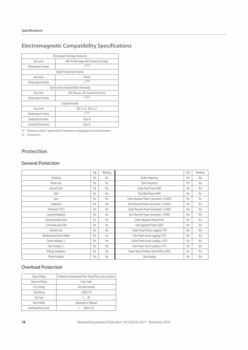
Electromagnetic Compatibility Specifications
Protection
General Protection
Overload Protection
Electrostatic Discharge Immunity
Test Level 8kV Air Discharge, 6kV Contact Discharge
Performance Criteria 1(1)(2)
(1) Performance Criteria 1 requires the DUT to experience no degradation or loss of performance
(2) Environment 2
Radio Frequency Immunity
Test Level 10V/m
Performance Criteria 1(1)(2)
Electrical Fast Transient/Burst Immunity
Test Level 4kV (Power), 2kV (Control & Comm)
Performance Criteria 1(1)(2)
Surge Immunity
Test Level 2kV (L-E), 1kV (L-L)
Performance Criteria 1(1)(2)
Radiated Emissions Class A
Conducted Emissions Class A
Trip Warning Trip Warning
Overload Yes Yes Under Frequency Yes Yes
Phase Loss Yes No Over Frequency Yes Yes
Ground Fault Yes Yes Under Real Power (kW) Yes Yes
Stall Yes No Over Real Power (kW) Yes Yes
Jam Yes Yes Under Reactive Power Consumed (+kVAR) Yes Yes
Underload Yes Yes Over Reactive Power Consumed (+kVAR) Yes Yes
Thermistor (PTC) Yes Yes Under Reactive Power Generated (-kVAR) Yes Yes
Current Imbalance Yes Yes Over Reactive Power Generated (-kVAR) Yes Yes
Communication Fault Yes Yes Under Apparent Power (kVA) Yes Yes
Communication Idle Yes Yes Over Apparent Power (kVA) Yes Yes
Remote Trip Yes No Under Power Factor Lagging (-PF) Yes Yes
Blocked Start/Start Inhibit Yes No Over Power Factor Lagging (-PF) Yes Yes
Under Voltage L-L Yes Yes Under Power Factor Leading (+PF) Yes Yes
Over Voltage L-L Yes Yes Over Power Factor Leading (+PF) Yes Yes
Voltage Unbalance Yes Yes Power Value Overflow (kW, kVAR or KVA) Yes Yes
Phase Rotation Yes Yes Over Analog Yes Yes
Type of Relay Ambient Compensated Time-Delay Phase Loss Sensitive
Nature of Relay Solid-State
FLA Setting See user manual
Trip Rating 120% FLA
Trip Class 5…30
Reset Mode Automatic or Manual
Overload Reset Level 1…100% TCU
Rockwell Automation Publication 193-SG010C-EN-P - November 2014 19
Specifications
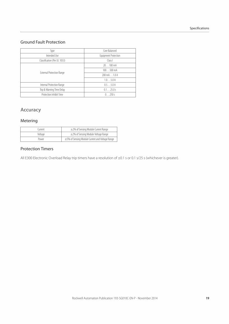
Ground Fault Protection
Accuracy
Metering
Protection Timers
All E300 Electronic Overload Relay trip timers have a resolution of ±0.1 s or 0.1 s/25 s (whichever is greater).
Type Core Balanced
Intended Use Equipment Protection
Classification (Per UL 1053) Class I
External Protection Range
20…100 mA
100…500 mA
200 mA…1.0 A
1.0…5.0 A
Internal Protection Range 0.5…5.0 A
Trip & Warning Time Delay 0.1…25.0 s
Protection Inhibit Time 0…250 s
Current ±2% of Sensing Module Current Range
Voltage ±2% of Sensing Module Voltage Range
Power ±5% of Sensing Module Current and Voltage Range

20 Rockwell Automation Publication 193-SG010C-EN-P - November 2014
Specifications
Notes:

Rockwell Automation Publication 193-SG010C-EN-P - November 2014 21
Approximate Dimensions
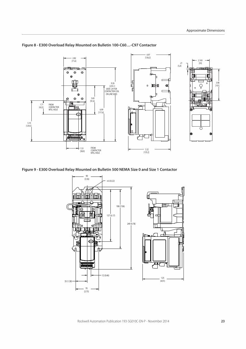
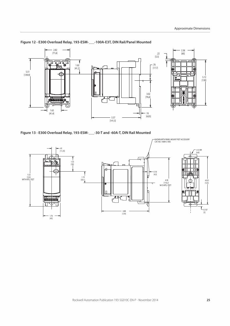
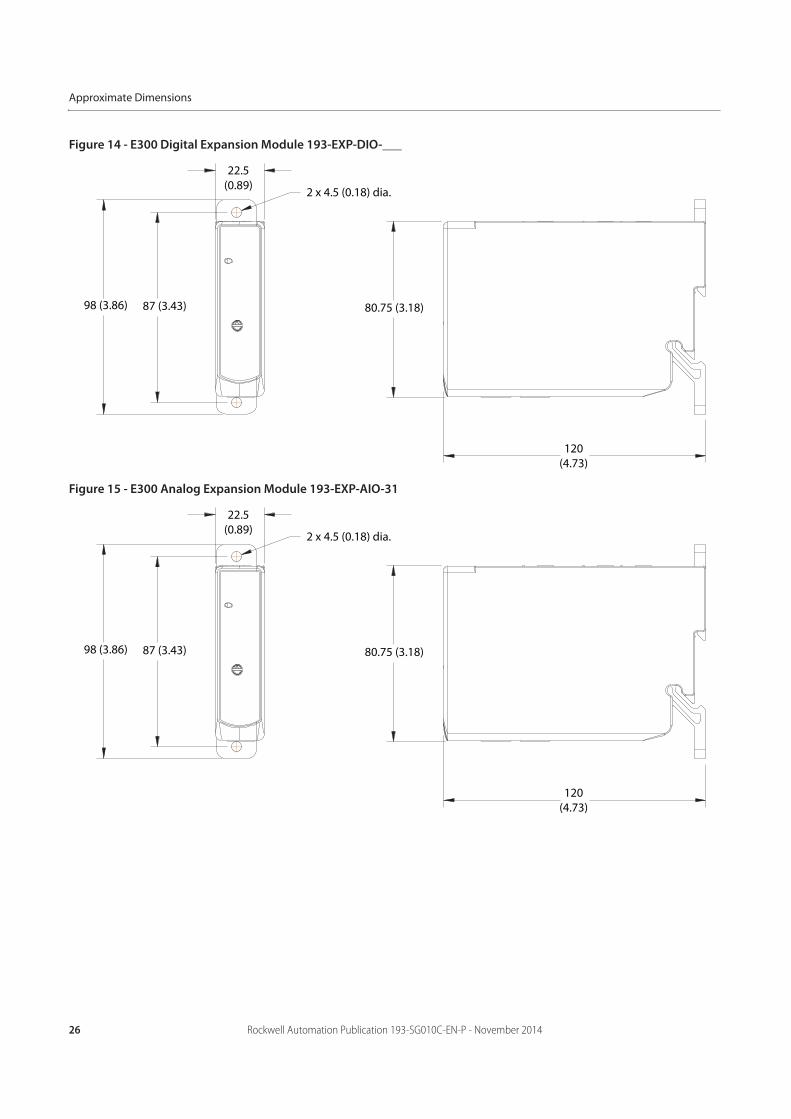
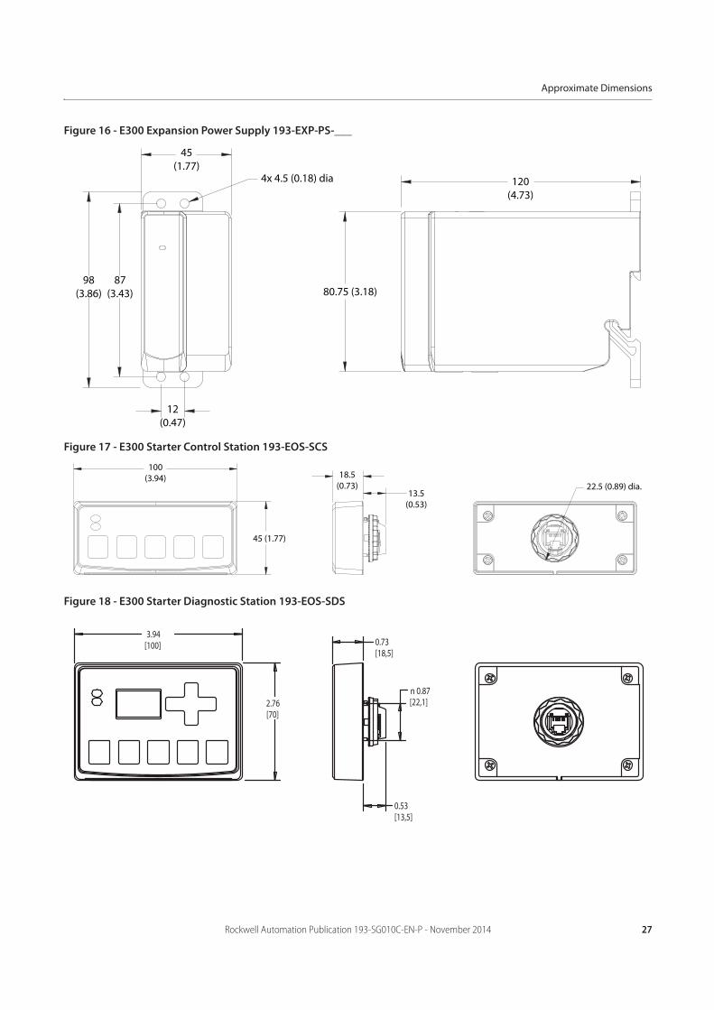
Bulletin 193/592-E300 Approximate Dimensions
Dimensions are in millimeters (inches). Dimensions are not intended to be used for manufacturing purposes.
Figure 5 - E300 Overload Relay Mounted on Bulletin 100-C09…-C23 Contactor
45(1.76)
87(3.40)
60 (2.36)
35(1.37)
n 5 (0.18)
190 (7.49)
37 (1.47)
122 (4.81)
29 (1.14) 122(4.78)
152 (5.98)
67 (2.65)
FROMCONTACTORMTG. HOLE
FROMCONTACTORMTG. HOLE
(ADD 5 mm (0.19 in.) FOR CONTACTOR COILON LINE SIDE)
22 Rockwell Automation Publication 193-SG010C-EN-P - November 2014
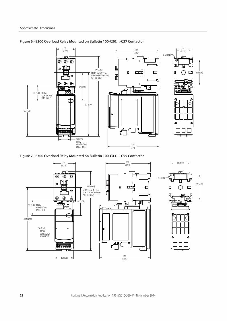
Approximate Dimensions
Figure 6 - E300 Overload Relay Mounted on Bulletin 100-C30…-C37 Contactor
Figure 7 - E300 Overload Relay Mounted on Bulletin 100-C43…-C55 Contactor
37 (1.48)
122 (4.81)
29 (1.13)
190 (7.49)
67 (2.65)
152 (5.98)
45(1.76)
122(4.78)
104(4.10)
35(1.374)
60 (2.36)
n 5 (0.18)
(ADD 5 mm (0.19 in.)FOR CONTACTOR COILON LINE SIDE)
FROMCONTACTORMTG. HOLE
FROMCONTACTORMTG. HOLE
54(2.12)
45 (1.76)
190 (7.49)
107(4.21)
60 (2.36)
45 (1.75)
n 5 (0.18)
37 (1.48)
34 (1.34)
122(4.82)
152 (5.98)
67 (2.65)FROMCONTACTORMTG. HOLE
FROMCONTACTORMTG. HOLE
(ADD 5 mm (0.19 in.)FOR CONTACTOR COILON LINE SIDE)
Rockwell Automation Publication 193-SG010C-EN-P - November 2014 23
Approximate Dimensions
Figure 8 - E300 Overload Relay Mounted on Bulletin 100-C60…-C97 Contactor
Figure 9 - E300 Overload Relay Mounted on Bulletin 500 NEMA Size 0 and Size 1 Contactor
2.82[71,6]
1.71[43,5]
5.10[129,5]
1.53[38,9]
3.60[91,6]
6.99[177,6]
9.26[235,1]
(ADD .24 FORCONTACTOR COIL
ON LINE SIDE)
4.97[126,2]
5.32[135,2]
3.98[101]
.21[5,4]
2.165[55]
FROMCONTACTORMTG. HOLE
FROMCONTACTORMTG. HOLE
180 (7.06)
157 (6.17)
249 (9.78)
35 (1.38)
70(2.75)
12 (0.46)
n 6 (0.22)
90(3.56)
125(4.91)

24 Rockwell Automation Publication 193-SG010C-EN-P - November 2014
Approximate Dimensions
Figure 10 - E300 Overload Relay Mounted on Bulletin 500 NEMA Size 2 Contactor
Figure 11 - E300 Overload Relay, 193-ESM-___-30A-E3T and -60A-E3T, DIN Rail/Panel Mounted
8.63(219.2)
7.24(183.9)
10.85(275.59)
n 0.22 (5.58)
3.94 (100.1)
1.58(40.13)
3.15(80.01)
4.91(124.71)
0.46 (11.68)
45(1.764)
135 (5.32)
30(1.18)
n 5 (0.17)
6 (0.24)
6 (0.217)
9 (0.33)
148 (5.83)
4 (0.154)
46 (1.81)
4 (0.14)
126(4.94)
101 (3.96)
4 (0.16)
8 (0.30)
q
Rockwell Automation Publication 193-SG010C-EN-P - November 2014 25
Approximate Dimensions
Figure 12 - E300 Overload Relay, 193-ESM-___-100A-E3T, DIN Rail/Panel Mounted
Figure 13 - E300 Overload Relay, 193-ESM-___-30-T and -60A-T, DIN Rail Mounted
2.82[71,6]
1.62[41,2]
1.63[41,4]
5.51[139,9]
5.57[141,5]
.70[17,7]
.16[4,05]
3.02[76,6]
2.36[60]
5.12[130]
.22[5,5]
q
5.32[135]
WITH MTG. FEET
0.18[4,5]
4.921[125]
0.197[5]
n 0.189[4,8]
4.58[116,2]
W/O MTG. FEET
1.53[39]
.45[11,35]
1.19[30,1]
1.76[45]
4.88[124]
SHOWN WITH PANEL MOUNT FEET ACCESSORYCAT. NO. 140M-C-N45
q
26 Rockwell Automation Publication 193-SG010C-EN-P - November 2014
Approximate Dimensions
Figure 14 - E300 Digital Expansion Module 193-EXP-DIO-___
Figure 15 - E300 Analog Expansion Module 193-EXP-AIO-31
2 x 4.5 (0.18) dia.
22.5(0.89)
80.75 (3.18)
120(4.73)
98 (3.86) 87 (3.43)
2 x 4.5 (0.18) dia.
22.5(0.89)
80.75 (3.18)
120(4.73)
98 (3.86) 87 (3.43)
Rockwell Automation Publication 193-SG010C-EN-P - November 2014 27
Approximate Dimensions
Figure 16 - E300 Expansion Power Supply 193-EXP-PS-___
Figure 17 - E300 Starter Control Station 193-EOS-SCS
Figure 18 - E300 Starter Diagnostic Station 193-EOS-SDS
120(4.73)
80.75 (3.18)
45(1.77)
4x 4.5 (0.18) dia
98(3.86)
87(3.43)
12(0.47)
100(3.94)
45 (1.77)
18.5(0.73)
13.5(0.53)
22.5 (0.89) dia.
3.94[100]
2.76[70]
0.73[18,5]
0.53[13,5]
n 0.87[22,1]

28 Rockwell Automation Publication 193-SG010C-EN-P - November 2014
Approximate Dimensions
Notes:


Publication 193-SG010C-EN-P - November 2014Supersedes Publication 193-SG010B-EN-P - April 2014 Copyright © 2014 Rockwell Automation, Inc. All rights reserved. Printed in the U.S.A.
Allen-Bradley, Rockwell Software, Rockwell Automation, and LISTEN. THINK. SOLVE are trademarks of Rockwell Automation, Inc.
Trademarks not belonging to Rockwell Automation are property of their respective companies.