Embed Size (px)
Citation preview
Lowara
50 Hz
Vertical MultistageElectric Pumpsequipped withhigh efficiency motors
e-SV™ Series1, 3, 5, 10, 15, 22, 33, 46, 66, 92, 125
uk version eSV_UKLIT0047_EN bw version.indd 1 11/10/2010 11:14:27

2
Lowarae-SV™ SERIESHYDRAULIC PERFORMANCE RANGE AT 50 Hz
WEB 07-2010
uk version eSV_UKLIT0047_EN bw version.indd 2 11/10/2010 11:14:27

3
Lowara
e-SV™ series specifications ....................................................................................................................5Characteristics of 1, 3, 5, 10, 15, 22, 33, 46, 66, 92, 125SV series ........................................................6General characteristics ...........................................................................................................................7Typical applications of e-SV™ pumps .....................................................................................................8Identification code ................................................................................................................................91, 3, 5SV series and 10, 15, 22SV series ��4 kW, pump cross section and main components ............1110, 15, 22SV series � 5,5 kW, pump cross section and main components ........................................12SV 33, 46, 66, 92 Series, Electric Pump Cross Section and Main Components ..................................13125SV series, pump cross section and main components .................................................................14Mechanical seals .............................................................................................................................15Motors ............................................................................................................................................18SVH series pumps with Hydrovar® Control system ............................................................................20Hydraulic performance range e-SV™ series at 50 Hz, 2 poles ...........................................................23Dimensions, weights, Operating characteristics at 50 Hz, 2 poles .....................................................28SV Series Replacement Guides .........................................................................................................52Accessories .....................................................................................................................................60Special versions ...............................................................................................................................63Technical appendix ..........................................................................................................................64
CONTENTS
uk version eSV_UKLIT0047_EN bw version.indd 3 11/10/2010 11:14:28
4
Lowara
uk version eSV_UKLIT0047_EN bw version.indd 4 11/10/2010 11:14:28

5
Lowara
APPLICATIONS��Handling of water, free of suspended solids, in the civil, industrial and agricultural sectors.��Pressure boosting and water supply systems.��Irrigation systems.��Wash systems.��Water treatment plants.��Handling of moderately aggressive liquids, demineralised water, water and glycol, etc.��Circulation of hot and cold water for heating, cooling and conditioning systems.��Boiler feed.��Pharmaceutical industries.��Food & beverage industries.
VerticalMultistageElectric Pumps
MARKET SECTORSCIVIL, AGRICULTURAL, LIGHT INDUSTRY, WATERTREATMENT, HEATING AND AIR CONDITIONING.
MOTOR� Squirrel cage in short circuit, enclosed construction with external ventilation.� Standard supply Lowara motors up to 22 kW (included) for the 2-pole version. Other motor brands for higher powers.� The Lowara SM � 0,75 kW and PLM surface motors have efficiency values that fall within the range normally referred to as efficiency class IE2 (EFF1).� IP55 protection.� Class F insulation.� Performances according to EN 60034-1.� Standard voltage: - Single-phase version: 220-240 V, 50 Hz. - Three-phase version: 220-240/380-415 V, 50 Hz for power up to 3 kW, 380-415/660-690 V, 50 Hz for power above 3 kW.
MATERIALS� Materials in contact are suitable for use with potable water (WRAS Approved).
❑ LIQUID END MADE ENTIRELY OF STAINLESS STEEL IN THE 1, 3, 5, 10, 15, 22 m3/h STANDARD VERSION
❑ STANDARD MECHANICAL SEAL CAN BE REPLACED WITHOUT REMOVING THE MOTOR FROM THE PUMP (FOR 10, 15, 22, 33, 46, 66, 92, 125)
❑ STANDARD MOTOR
❑ CAN BE USED WITH THE HYDROVAR® CONTROL SYSTEM IN ORDER TO MANAGE THE OPERATION OF THE PUMP BASED ON THE SYSTEM CONDITIONS AND SAVE ENERGY
e-SV™ serieswith high efficiencymotors
SPECIFICATIONSPUMPThe SV pump is a non-self primingvertical multistage pump coupled to astandard motor.The liquid end, located between theupper cover and the pump casing, isheld in place by tie rods. The pumpcasing is available with differentconfigurations and connection types. � Delivery: up to 160 m3/h.� Head: up to 265 m.� Temperature of pumped liquid: - from -30°C to +120°C for standard version. � Maximum operating pressure: - 1, 3, 5, 10, 15, 22SV with oval flanges: 16 bar (PN16). - 1, 3, 5, 10, 15, 22SV with round flanges or Victaulic®, Clamp or DIN 11851 connections: 25 bar (PN 25). - SV 33, 46: 16, 25, 40 bar (PN 16, PN 25 or PN 40). - SV 66, 92: 16, 25 bar (PN 16, PN 25).� Tested in compliance with ISO 9906 - Annex A.� Direction of rotation: clockwise looking at the pump from the top down (marked with an arrow on the adapter and on the coupling).
uk version eSV_UKLIT0047_EN bw version.indd 5 11/10/2010 11:14:29

6
LowaraCHARACTERISTICS OF 1, 3, 5, 10, 15, 22SV SERIES
� Vertical multistage centrifugal pump. All metal parts in contact with the pumped liquid are made of stainless steel.� The following versions are available: - F: round flanges, in-line delivery and suction ports, AISI 304. - T: oval flanges, in-line delivery and suction ports, AISI 304. - R: round flanges, delivery port above the suction port, with four adjustable positions, AISI 304. - N: round flanges, in-line delivery and suction ports, AISI 316. - V: Victaulic® couplings, in-line delivery and suction ports, AISI 316. - C: Clamp couplings (DIN 32676), in-line delivery and suction ports, AISI 316. - K: threaded couplings, (DIN 11851), in-line delivery and suction ports, AISI 316.� Reduced axial thrusts enable the use of standard motors that are easily found in the market. The Lowara SM � 0,75 kW and PLM surface motors have efficiency values that fall within the range normally referred to as efficiency class IE2.� Seal housing chamber designed to prevent the accumulation of air in the critical area next to the mechanical seal.
� Mechanical seal according to EN 12756 (ex DIN 24960) and ISO 3069 for 1, 3, 5SV and 10, 15, 22SV (� 4 kW) series.� Balanced mechanical seal according to EN 12756 (ex DIN 24960) and ISO 3069, which can be replaced without removing the motor from the pump for 10, 15 and 22SV (� 5,5 kW) series.� Seal housing chamber designed to prevent the accumulation of air in the critical area next to the mechanical seal.� A second plug is available for 10, 15, 22SV series.� Versions with round flanges that can be coupled to counter-flanges, according to EN 1092.� Threaded, oval counter-flanges made of stainless steel are standard supply for the T versions.� Round counter-flanges made of stainless steel are available on request for the F, R and N versions.� Easy maintenance. No special tools required for assembly or disassembly.� Materials are suitable for handling potable water (WRAS Approved).� Standard version for temperatures ranging from -30°C to +120°C.
CHARACTERISTICS OF 33, 46, 66, 92, 125SV SERIES
� Vertical multistage centrifugal pump with impellers, diffusers and outer sleeve made entirely of stainless steel, and with pump casing and motor adapter made of cast iron in the standard version.� N version made entirely of AISI 316 stainless steel.� Innovative axial load compensation system on pumps with higher head. This ensures reduced axial thrusts and enable the use of standard motors that are easily found in the market. The Lowara surface motors have efficiency value that fall within the range normally referred to as efficiency class IE2.� Balanced mechanical seal according to EN 12756 (ex DIN 24960) and ISO 3069, which can be replaced without removing the motor
from the pump.� Seal housing chamber designed to prevent the accumulation of air in the critical area next to the mechanical seal.� Materials are suitable for handling potable water (WRAS Approved).� Standard version for temperatures ranging from -30°C to +120°C.� Pump body fitted with couplings for installing pressure gauges on both suction and delivery flanges.� In-line ports with round flanges that can be coupled to counter-flanges, in compliance with EN 1092.� Mechanical sturdiness and easy maintenance. No special tools required for assembly or disassembly.
AVAILABLE ON REQUESTSpecial versions are available to suit many applications. For details see page 63.
Inlet pressure of the pump plus static pressure of the water within the pump can not exceed the nominal pressure (PN). Lowara standard motors have an axially locked shaft with no restrictions; using different motors there could be limitations for the inlet pressure, in this case please contact our customer service.
uk version eSV_UKLIT0047_EN bw version.indd 6 11/10/2010 11:14:29

7
Lowara
VERSION DIAGRAM
GENERAL CHARACTERISTICS 2-POLE SV
1, 3, 5, 10, 15, 22SV VERSIONS
125SV VERSIONS
VERSION DIAGRAM
1SV 3SV 5SV SV10 15SV 22SV SV33 SV46 SV66 SV92 125SV
Max efficiency flow (m³/h) 1,7 3 5,5 10,5 16,5 20,5 31 43 72 90 120
Flow range (m³/h) 0,7÷2,4 1,2÷4,4 2,4÷8,5 5÷14 8÷24 11÷29 15÷40 22÷60 30÷85 45÷120 60÷160
Maximum pressure ( bar ) 23 25 25 25 25 26 30 36 23 21 22
Motor power ( kW ) 0,37÷2,2 0,37÷3 0,37÷5.5 0,75÷11 1,1÷15 1,1÷18,5 2.2÷30 3÷45 4÷45 5.5÷45 7,5÷55
Max ( % ) of pump 50 60 70 71 72 73 76,5 79 78 79,5 78
Standard temperature ( °C ) -30 +120
uk version eSV_UKLIT0047_EN bw version.indd 7 11/10/2010 11:14:29

8
LowaraTYPICAL APPLICATIONS OF e-SV™ SERIES ELECTRIC PUMPS
WATER SUPPLY AND PRESSUREBOOSTING• Pressure boosting in building, hotel, residential complexes.• Pressure booster stations, supply of water networks.• Booster packages.
WATER TREATMENT• Ultrafiltration systems.• Reverse osmosis systems.• Water softeners and de-mineralization.• Distillation systems.• Filtration.
LIGHT INDUSTRY• Washing and cleaning plants (washing and degreasing of mechanical parts, car and truck wash tunnels, washing of electronic industry circuits).• Commercial washers.• Firefighting system pumps.
PHARMACEUTICAL AND FOOD & BEVERAGE INDUSTRIES• Production plant where are required specific sanitary standards.
IRRIGATION AND AGRICULTURE• Greenhouses.• Humidifiers.• Sprinkler irrigation.
HEATING, VENTILATION AND AIRCONDITIONING (HVAC)• Cooling towers and systems.• Temperature control systems.• Refrigerators.• Induction heating.• Heat exchangers.• Boilers, water recirculation and heating.
uk version eSV_UKLIT0047_EN bw version.indd 8 11/10/2010 11:14:31

9
LowaraIDENTIFICATION CODE 1, 3, 5, 10, 15, 22SV
22
Flow rate in m3/h
Null = 2 POLES4 = 4 POLES
L 110 T
M = SINGLE-PHASET = THREE-PHASE
Series name
Number of impellers
4F10SV
L = Low NPSH, round flanges, PN 25 (F, N versions)H = High temperature, round flanges, PN 25 (F, N versions)D = Clean and Dry (F, N, V, C, K versions)E = Passivated and Electro polished (N, V, C, K versions)
Rated motor power (kW x 10)
F = AISI 304, round flanges (PN 25)T = AISI 304, oval flanges (PN 16)R = AISI 304, discharge port above suction, round flanges (PN 25)N = AISI 316, round flanges (PN 25)V = AISI 316, Victaulic couplings (PN 25)P = AISI 316, Victaulic couplings (PN 40)C = AISI 316, Clamp couplings DIN 32676 (PN 25)K = AISI 316, Threaded couplings DIN 11851 (PN 25)
EXAMPLE: 22SV10F110TSV series electric pump, flow rate 22 m3/h, Number of impellers 10, F version (AISI 304) round flanges, rated motor power 11 kW, 50 Hz frequency, three-phase.
Null = 50 Hz6 = 60 Hz
IDENTIFICATION CODE 33, 46, 66, 92
4 Poles)
uk version eSV_UKLIT0047_EN bw version.indd 9 11/10/2010 11:14:31

10
Lowara
125
Flow rate in m3/h
Null = 2 POLES4 = 4 POLES
L 550 T
M = SINGLE-PHASET = THREE-PHASE
Series name
Number of impellers(8/2 = 8 impellers, including 2 reduced ones, A = reduction type)
IDENTIFICATION CODE 125SV
4GSV
L = Low NPSH, round flanges, (G, N versions)H = High temperature, round flanges, (G, N versions)D = Clean and Dry (N versions)E = Passivated and Electro polished (N versions)
Rated motor power (kW x 10)
G = AISI 304/Cast iron, round flangesN = AISI 316, round flangesP = AISI 316, round flanges (PN 40)
EXAMPLE: 125SV8/3AG550TSV series electric pump, flow rate 125 m3/h, Number of impellers 8, including 2 reduced ones, A reduction type G version (AISI 304/Cast iron) round flanges, rated motor power 55 kW, 50 Hz frequency, three-phase.
Null = 50 Hz6 = 60 Hz
8/2A
uk version eSV_UKLIT0047_EN bw version.indd 10 11/10/2010 11:14:31

11
Lowara1, 3, 5SV SERIES and 10, 15, 22SV SERIES � 4 kW ELECTRIC PUMP CROSS SECTION AND MAIN COMPONENTS
MATERIALI 1-22 SV VERSIONI F-T-R
REF. NAME MATERIAL
N. EUROPE USA
1 Pump body Stainless steel EN 10088-1-X5CrNi18-10 (1.4301) AISI 3042 Impeller Stainless steel EN 10088-1-X5CrNi18-10 (1.4301) AISI 3043 Diffuser Stainless steel EN 10088-1-X5CrNi18-10 (1.4301) AISI 3044 Outer sleeve Stainless steel EN 10088-1-X5CrNi18-10 (1.4301) AISI 3045 Shaft Stainless steel EN 10088-1-X5CrNi18-10 (1.4301) AISI 3046 Adapter Cast iron EN 1561-GJL-250 (JL1040) ASTM Class 357 Base Aluminium EN 1706-AC-AlSi11Cu2 (Fe) (AC46100) -8 Coupling Aluminium EN 1706-AC-AlSi11Cu2 (Fe) (AC46100) -9 Seal housing Stainless steel EN 10088-1-X5CrNi18-10 (1.4301) AISI 304
10 Mechanical seal Silicon carbide / Carbon / EPDM 11 Elastomers EPDM12 Coupling protection Stainless steel EN 10088-1-X5CrNi18-10 (1.4301) AISI 30413 Shaft sleeve and bushing Tungsten carbide14 Fill / drain plugs Stainless steel EN 10088-1-X5CrNi18-10 (1.4301) AISI 30415 Tie rods Stainless steel EN 10277-3-36SMnPb14 (1.0765)16 Wear ring Technopolymer PPS
1-22sv-ftr-en_a_tm
REFERENCE STANDARDS
MATERIALI 1-22SV VERSIONI N-V-C-K
REF. NAME MATERIAL
N. EUROPE USA
1 Pump body Stainless steel EN 10088-1-X2CrNiMo17-12-2 (1.4404) AISI 316L2 Impeller Stainless steel EN 10088-1-X2CrNiMo17-12-2 (1.4404) AISI 316L3 Diffuser and upper spacer Stainless steel EN 10088-1-X2CrNiMo17-12-2 (1.4404) AISI 316L4 Outer sleeve Stainless steel EN 10088-1-X2CrNiMo17-12-2 (1.4404) AISI 316L5 Shaft Stainless steel EN 10088-1-X5CrNiMo17-12-2 (1.4401) AISI 3166 Adapter Cast iron EN 1561-GJL-250 (JL1040) ASTM Class 357 Base Aluminium EN 1706-AC-AlSi11Cu2 (Fe) (AC46100) -8 Coupling Aluminium EN 1706-AC-AlSi11Cu2 (Fe) (AC46100) -9 Seal housing Stainless steel EN 10088-1-X2CrNiMo17-12-2 (1.4404) AISI 316L
10 Mechanical seal Silicon carbide / Carbon / EPDM 11 Elastomers EPDM12 Coupling protection Stainless steel EN 10088-1-X5CrNi18-10 (1.4301) AISI 30413 Shaft sleeve and bushing Tungsten carbide14 Fill / drain plugs Stainless steel EN 10088-1-X5CrNiMo17-12-2 (1.4401) AISI 31615 Tie rods Stainless steel EN 10088-1-X17CrNi16-2 (1.4057) AISI 43116 Wear ring Technopolymer PPS
1-22sv-nvck-en_a_tm
REFERENCE STANDARDS
N, V, C, K VERSIONS
F, T, R VERSIONS
uk version eSV_UKLIT0047_EN bw version.indd 11 11/10/2010 11:14:32
12
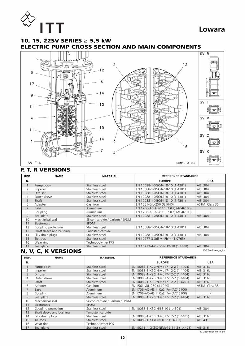
Lowara10, 15, 22SV SERIES � 5,5 kWELECTRIC PUMP CROSS SECTION AND MAIN COMPONENTS
MATERIALI 10-22 SV VERSIONI F-T-R
REF. NAME MATERIAL
N. EUROPE USA
1 Pump body Stainless steel EN 10088-1-X5CrNi18-10 (1.4301) AISI 3042 Impeller Stainless steel EN 10088-1-X5CrNi18-10 (1.4301) AISI 3043 Diffuser Stainless steel EN 10088-1-X5CrNi18-10 (1.4301) AISI 3044 Outer sleeve Stainless steel EN 10088-1-X5CrNi18-10 (1.4301) AISI 3045 Shaft Stainless steel EN 10088-1-X5CrNi18-10 (1.4301) AISI 3046 Adapter Cast iron EN 1561-GJL-250 (JL1040) ASTM Class 357 Base Aluminium EN 1706-AC-AlSi11Cu2 (Fe) (AC46100) -8 Coupling Aluminium EN 1706-AC-AlSi11Cu2 (Fe) (AC46100) -9 Seal plate Stainless steel EN 10088-1-X5CrNi18-10 (1.4301) AISI 304
10 Mechanical seal Silicon carbide / Carbon / EPDM 11 Elastomers EPDM12 Coupling protection Stainless steel EN 10088-1-X5CrNi18-10 (1.4301) AISI 30413 Shaft sleeve and bushing Tungsten carbide14 Fill / drain plugs Stainless steel EN 10088-1-X5CrNi18-10 (1.4301) AISI 30415 Tie rods Stainless steel EN 10277-3-36SMnPb14 (1.0765)16 Wear ring Technopolymer PPS17 Seal gland Stainless steel EN 10213-4-GX5CrNi19-10 (1.4308) AISI 304
10-22sv-ftr-en_a_tm
REFERENCE STANDARDS
MATERIALI 10-22SV VERSIONI N-V-C-K
REF. NAME MATERIAL
N. EUROPE USA
1 Pump body Stainless steel EN 10088-1-X2CrNiMo17-12-2 (1.4404) AISI 316L2 Impeller Stainless steel EN 10088-1-X2CrNiMo17-12-2 (1.4404) AISI 316L3 Diffuser Stainless steel EN 10088-1-X2CrNiMo17-12-2 (1.4404) AISI 316L4 Outer sleeve Stainless steel EN 10088-1-X2CrNiMo17-12-2 (1.4404) AISI 316L5 Shaft Stainless steel EN 10088-1-X5CrNiMo17-12-2 (1.4401) AISI 3166 Adapter Cast iron EN 1561-GJL-250 (JL1040) ASTM Class 357 Base Aluminium EN 1706-AC-AlSi11Cu2 (Fe) (AC46100) -8 Coupling Aluminium EN 1706-AC-AlSi11Cu2 (Fe) (AC46100) -9 Seal plate Stainless steel EN 10088-1-X2CrNiMo17-12-2 (1.4404) AISI 316L
10 Mechanical seal Silicon carbide / Carbon / EPDM 11 Elastomers EPDM12 Coupling protection Stainless steel EN 10088-1-X5CrNi18-10 (1.4301) AISI 30413 Shaft sleeve and bushing Tungsten carbide14 Fill / drain plugs Stainless steel EN 10088-1-X5CrNiMo17-12-2 (1.4401) AISI 31615 Tie rods Stainless steel EN 10088-1-X17CrNi16-2 (1.4057) AISI 43116 Wear ring Technopolymer PPS17 Seal gland Stainless steel EN 10213-4-GX5CrNiMo19-11-2 (1.4408) AISI 316
10-22sv-nvck-en_a_tm
REFERENCE STANDARDS
N, V, C, K VERSIONS
F, T, R VERSIONS
uk version eSV_UKLIT0047_EN bw version.indd 12 11/10/2010 11:14:32

13
Lowara
33, 46, 66, 92 SV SERIESELECTRIC PUMP CROSS SECTION AND MAIN COMPONENTS
uk version eSV_UKLIT0047_EN bw version.indd 13 11/10/2010 11:14:33
14
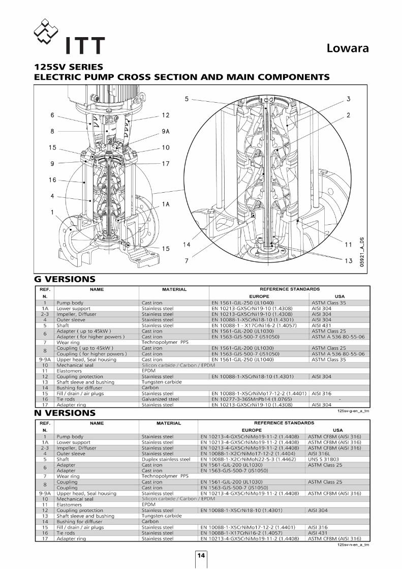
Lowara125SV SERIESELECTRIC PUMP CROSS SECTION AND MAIN COMPONENTS
G VERSIONS
N VERSIONS
uk version eSV_UKLIT0047_EN bw version.indd 14 11/10/2010 11:14:33

15
Lowara
TENUTA MECCANICA SV MATERIALI
Q1 : Silicon Carbide E : EPDM GG : AISI 316 B : Resin impregnated carbon V : FPM C : Special resin impregnated carbon T : PTFE
sv_ten-mec-en_a_tm
POSITION 1 - 2 POSITION 3 POSITION 4 - 5
e-SV™ SERIESMECHANICAL SEALS, ACCORDING TO EN 12756
LIST OF MATERIALS
TYPE OF SEAL
1, 3, 5SV 10, 15, 22SV � 4 kW
10, 15, 22SV � 5,5 kW
125SV
uk version eSV_UKLIT0047_EN bw version.indd 15 11/10/2010 11:14:35
16
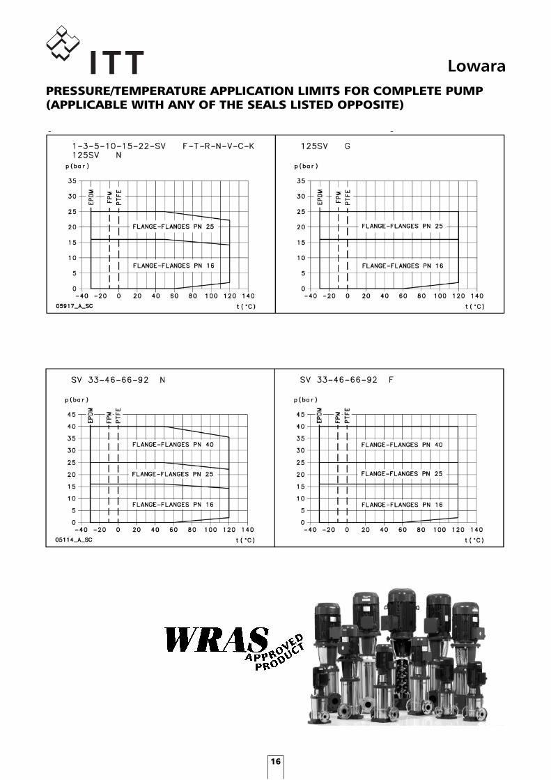
LowaraPRESSURE/TEMPERATURE APPLICATION LIMITS FOR COMPLETE PUMP(APPLICABLE WITH ANY OF THE SEALS LISTED OPPOSITE)
uk version eSV_UKLIT0047_EN bw version.indd 16 11/10/2010 11:14:36

17
LowaraCOMPATIBILITY CHART FOR MATERIALS IN CONTACT WITHMOST COMMONLY USED LIQUIDS
uk version eSV_UKLIT0047_EN bw version.indd 17 11/10/2010 11:14:37
18
Lowarae-SV™ SERIESMOTORS
SINGLE-PHASE MOTORS AT 50 Hz, 2-POLE
THREE-PHASE MOTORS AT 50 Hz, 2-POLE
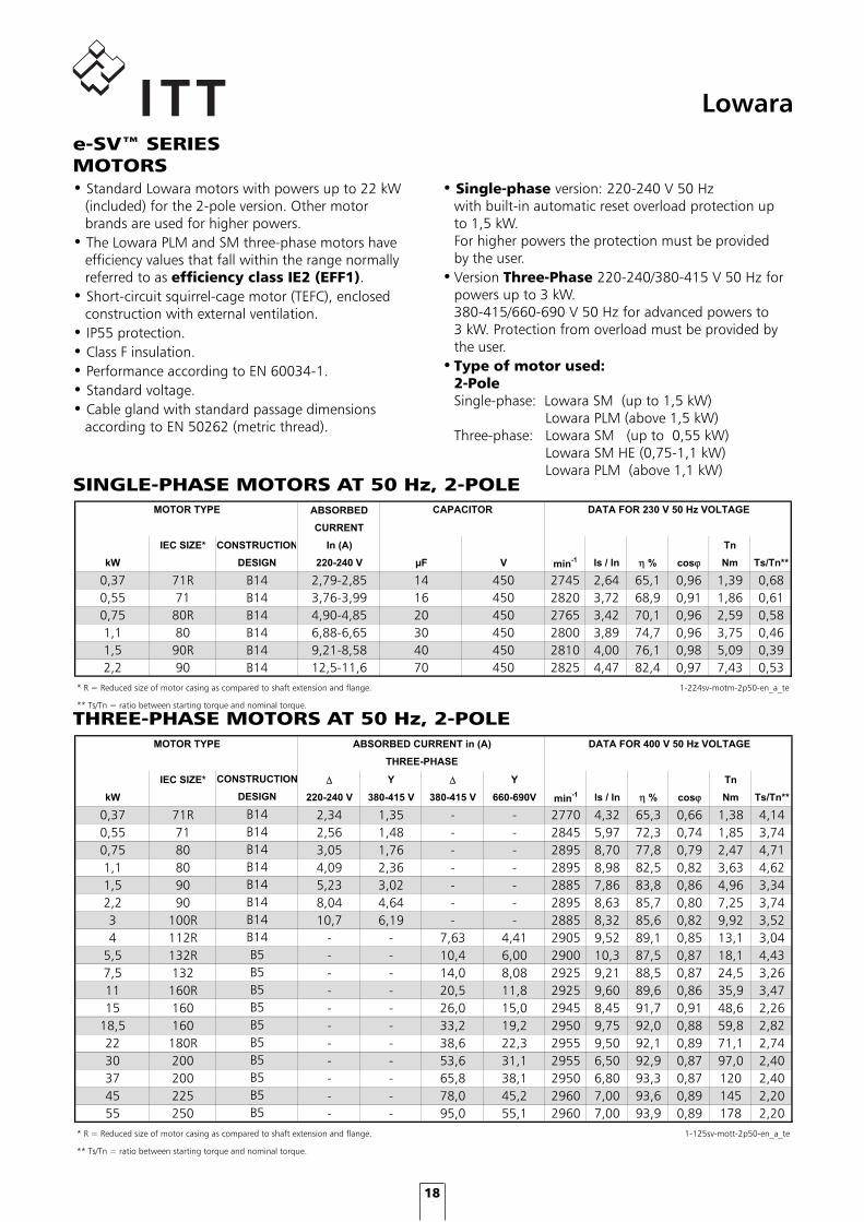
• Standard Lowara motors with powers up to 22 kW (included) for the 2-pole version. Other motor brands are used for higher powers.• The Lowara PLM and SM three-phase motors have efficiency values that fall within the range normally referred to as efficiency class IE2 (EFF1).• Short-circuit squirrel-cage motor (TEFC), enclosed construction with external ventilation.• IP55 protection.• Class F insulation.• Performance according to EN 60034-1.• Standard voltage.• Cable gland with standard passage dimensions according to EN 50262 (metric thread).
• Single-phase version: 220-240 V 50 Hz with built-in automatic reset overload protection up to 1,5 kW. For higher powers the protection must be provided by the user.• Version Three-Phase 220-240/380-415 V 50 Hz for powers up to 3 kW. 380-415/660-690 V 50 Hz for advanced powers to 3 kW. Protection from overload must be provided by the user.• Type of motor used: 2-Pole Single-phase: Lowara SM (up to 1,5 kW) Lowara PLM (above 1,5 kW) Three-phase: Lowara SM (up to 0,55 kW) Lowara SM HE (0,75-1,1 kW) Lowara PLM (above 1,1 kW)MOTORI MONOFASE PER SERIE 1-22 SV 50 Hz, 2 poli
ABSORBED
CURRENT
IEC SIZE* CONSTRUCTION In (A) Tn
kW DESIGN 220-240 V �F V min-1 ls / ln ηη % cosϕ Nm Ts/Tn**
0,37 71R B14 2,79-2,85 14 450 2745 2,64 65,1 0,96 1,39 0,680,55 71 B14 3,76-3,99 16 450 2820 3,72 68,9 0,91 1,86 0,610,75 80R B14 4,90-4,85 20 450 2765 3,42 70,1 0,96 2,59 0,581,1 80 B14 6,88-6,65 30 450 2800 3,89 74,7 0,96 3,75 0,461,5 90R B14 9,21-8,58 40 450 2810 4,00 76,1 0,98 5,09 0,392,2 90 B14 12,5-11,6 70 450 2825 4,47 82,4 0,97 7,43 0,53
* R = Reduced size of motor casing as compared to shaft extension and flange. 1-224sv-motm-2p50-en_a_te
** Ts/Tn = ratio between starting torque and nominal torque.
MOTOR TYPE DATA FOR 230 V 50 Hz VOLTAGECAPACITOR
MOTORI TRIFASE PER SERIE 1-125 SV 50 Hz, 2 poli
IEC SIZE* Δ Y Δ Y Tn
kW 220-240 V 380-415 V 380-415 V 660-690V min-1 ls / ln η % cosϕ Nm Ts/Tn**
0,37 71R 2,34 1,35 - - 2770 4,32 65,3 0,66 1,38 4,140,55 71 2,56 1,48 - - 2845 5,97 72,3 0,74 1,85 3,740,75 80 3,05 1,76 - - 2895 8,70 77,8 0,79 2,47 4,711,1 80 4,09 2,36 - - 2895 8,98 82,5 0,82 3,63 4,621,5 90 5,23 3,02 - - 2885 7,86 83,8 0,86 4,96 3,342,2 90 8,04 4,64 - - 2895 8,63 85,7 0,80 7,25 3,743 100R 10,7 6,19 - - 2885 8,32 85,6 0,82 9,92 3,524 112R - - 7,63 4,41 2905 9,52 89,1 0,85 13,1 3,04
5,5 132R - - 10,4 6,00 2900 10,3 87,5 0,87 18,1 4,437,5 132 - - 14,0 8,08 2925 9,21 88,5 0,87 24,5 3,2611 160R - - 20,5 11,8 2925 9,60 89,6 0,86 35,9 3,4715 160 - - 26,0 15,0 2945 8,45 91,7 0,91 48,6 2,26
18,5 160 - - 33,2 19,2 2950 9,75 92,0 0,88 59,8 2,8222 180R - - 38,6 22,3 2955 9,50 92,1 0,89 71,1 2,7430 200 - - 53,6 31,1 2955 6,50 92,9 0,87 97,0 2,4037 200 - - 65,8 38,1 2950 6,80 93,3 0,87 120 2,4045 225 - - 78,0 45,2 2960 7,00 93,6 0,89 145 2,2055 250 - - 95,0 55,1 2960 7,00 93,9 0,89 178 2,20
* R = Reduced size of motor casing as compared to shaft extension and flange. 1-125sv-mott-2p50-en_a_te
** Ts/Tn = ratio between starting torque and nominal torque.
DATA FOR 400 V 50 Hz VOLTAGE
CONSTRUCTION
MOTOR TYPE ABSORBED CURRENT in (A)
THREE-PHASE
DESIGN
B14B14B14B14B14B14B14B14B5B5
B5B5
B5B5B5B5B5B5
uk version eSV_UKLIT0047_EN bw version.indd 18 11/10/2010 11:14:39

19
Lowara
The tables show the mean sound pressure (Lp) measured as per Curve A (Standard ISO 1680).Noise values were measured with the 50 Hz motor running idle with a tolerance of 3 dB (A).
2-POLE MOTORS
e-SV™ SERIESMOTOR NOISE
RUMOROSITA' MOTORI SV 2-POLI 50Hz
POWER MOTOR TYPE
kW IEC SIZE*
0,37 71R0,55 710,75 80R1,1 801,5 90R2,2 90R3 100R4 112R
5,5 132R7,5 13211 160R15 160
18,5 16022 180R30 20037 20045 22555 250
*R = Reduced motor casing size with respect 1-125sv_mott_2p50-en_a_tr to shaft extension and related flange.
<70<70<70
7270
<70
<70<70<70<70
<70
72
75
71737173
75
NOISE
LpA
dB
uk version eSV_UKLIT0047_EN bw version.indd 19 11/10/2010 11:14:39

20
LowaraSVH SERIES ELECTRIC PUMPS WITH HYDROVAR® CONTROLSYSTEMThe Lowara SV electric pumps are available in the SVHversion, i.e. coupled to Hydrovar®, the microprocessor based control unit designed to manage the performance of the pump based on the conditions and requirements of the system. The basic SV electric pump is thustransformed into a complete pumping system suitable for a number of applications, including:• Variable speed pressure boosting (constant pressure is maintained in industrial, civil and agricultural applications).• Water filtration and treatment (constant flow is maintained based on flow resistance).• Air conditioning and heating (constant differential pressure is maintained in a closed circuit).
• No special pumps or motors: HYDROVAR®
is mounted directly onto a standard three-phase TEFC motor with class F insulation up to 22 kW power. A wall-mounted version is available for higher powers, up to 45 kW.
• No separate pressure sensors: HYDROVAR® is equipped with a pressure transmitter or differential pressure transmitter, depending on the applications.
• No separate microprocessors: In multiple-pump systems the microprocessor regulates the sequential operation of the pumps or motors. Since HYDROVAR® features a built-in microprocessor, no other control devices are required.
• No separate control panels or converters: HYDROVAR® performs all the functions of a pump control panel, incorporating protections against overload, short circuit, high temperature, etc. The only external device required is a fuse on the power supply line. Will depend upon any local electrical installation regulations.
• No by-pass lines or safety systems: With HYDROVAR® the pump switches off immediately when demand is zero or exceeds the maximum capacity of the pump. This way there is no need to install additional safety devices.
• No large diaphragm tanks are required: Without a supply tank, a constant speed pump run- ning at maximum power will be constantly switching on and off in order to satisfy system demands. With
the HYDROVAR® system the speed of each pump varies in order to maintain a constant pressure or flow. A small surge tank is sufficient to maintain system pressure at zero demand, therefore there is no need to install a large tank. Where local regulations allow it, the HYDROVAR® systems can be connected directly to the water supply line, so there is no need to install large storage tanks on the suction side. The pump’s operation at the correct speed based on system requirements enables energy consumption to be substantially reduced.
• Anti-condensation heater All the units are equipped with anti-condensation heaters that switch on when the pump is in standby mode.
uk version eSV_UKLIT0047_EN bw version.indd 20 11/10/2010 11:14:40

21
LowaraOPERATING PRINCIPLE
The basic function of the HYDROVAR® device is tocontrol the pump to meet the system demands.
HYDROVAR® performs these functions by:1) Measuring the system pressure or flow via a transmitter mounted on the pump’s delivery side.2) Calculating the motor speed to maintain the correct flow or pressure.3) Sending out a signal to the pump to start the motor, increase speed, decrease speed or stop.4) In the case of multiple pump installations, HYDROVAR® will automatically provide for the cyclic changeover of the pump‘s starting sequence.
In addition to these basic functions, HYDROVAR® can dothings only by the most advanced computerised controlsystems, such as:• Stop the pump(s) at zero demand.• Stop the pump(s) in case of water failure on the suction side (protection against dry running).• Stop the pump if the required delivery exceeds the pump’s capacity (protection against cavitation caused by excessive demand), or automatically switch on the next pump in a multiple series.• Protect the pump and motor from overvoltage, undervoltage, overload and earth fault.• Vary the pump speed acceleration and deceleration time.• Compensate for increased flow resistance at high flow rates.• Conduct automatic test starts at set intervals.• Monitor the converter and motor operating hours.• Display all functions on an LCD in different languages (Italian, English, French, German, Spanish, Portuguese, Dutch).• Send a signal to a remote control system which is proportional to the pressure and frequency.• Communicate with another HYDROVAR® or control system via an RS 485 interface.
TYPICAL EXAMPLE OF ENERGY SAVINGSSystem: 22SV07F75T vertical multistage electric pump with 7,5 kW motor equipped with HYDROVAR®, 70 m head. 19 hour/day operation.Application: maintaining a constant pressure as the flow rate varies.
Control for constant pressure
Control to match a system curve
Control for constant flow
Control according to an external signal
TABELLA RISPARMIO ENERGETICO
FLOW POWER OPERATING TOTAL
CONSTANT SPEED VARIABLE SPEED SAVED TIME ENERGY
PUMP PUMP SAVINGS
m3/h kW kW kW (hours) kWh
24 7,4 7,4 0,0 876 - 21 6,9 6,1 0,8 876 701 18 6,5 5,0 1,5 1752 2.628 14 5,6 3,8 1,8 1752 3.154 10 5,1 2,8 2,3 1752 4.030
10.512
sv-hydr-en_a_te
YEARLY ENERGY SAVINGS (kWh)
ABSORBED POWER
uk version eSV_UKLIT0047_EN bw version.indd 21 11/10/2010 11:14:40

22
Lowarae-SV™ SERIESHYDRAULIC PERFORMANCE RANGE AT 50 Hz, 2 POLES
uk version eSV_UKLIT0047_EN bw version.indd 22 11/10/2010 11:14:41

23
Lowara1, 3, 5SV SERIESHYDRAULIC PERFORMANCE TABLE AT 50 Hz, 2 POLESTABELLA DI PRESTAZIONI IDRAULICHE SERIE 1SV 3SV 5SV 2p 50 Hz
PUMP
TYPE l/min 0 12 20 25 30 35 40 45 50 60 73 100 120 141
m3/h 0 0,7 1,2 1,5 1,8 2,1 2,4 2,7 3,0 3,6 4,4 6,0 7,2 8,5
kW HP
1SV02 0,37 0,5 12,2 12,2 11,5 10,7 9,5 7,9 6,01SV03 0,37 0,5 18,0 18,0 17,0 15,7 13,8 11,4 8,41SV04 0,37 0,5 23,7 23,5 22,1 20,4 17,9 14,6 10,61SV05 0,37 0,5 29,3 28,9 27,0 24,8 21,6 17,4 12,51SV06 0,37 0,5 34,8 34,2 31,7 28,9 25,0 20,0 14,01SV07 0,37 0,5 40,2 39,2 36,1 32,7 28,1 22,2 15,21SV08 0,55 0,75 48,1 47,9 45,2 41,8 36,8 30,4 22,41SV09 0,55 0,75 53,7 53,4 50,4 46,4 40,8 33,5 24,61SV10 0,55 0,75 59,4 59,0 55,5 51,0 44,7 36,6 26,61SV11 0,55 0,75 65,1 64,5 60,4 55,5 48,5 39,5 28,51SV12 0,75 1 73,3 73,1 69,3 64,3 57,1 47,6 35,71SV13 0,75 1 79,2 78,9 74,8 69,4 61,6 51,2 38,21SV15 0,75 1 90,9 90,5 85,6 79,3 70,1 58,1 43,11SV17 1,1 1,5 105,2 104,9 100,0 93,1 82,6 68,6 51,21SV19 1,1 1,5 117,0 116,7 111,0 103,2 91,5 75,8 56,31SV22 1,1 1,5 134,6 134,1 127,4 118,1 104,4 86,1 63,51SV25 1,5 2 152,6 152,4 145,5 135,4 120,0 99,1 72,71SV27 1,5 2 164,3 164,0 156,4 145,4 128,8 106,1 77,51SV30 1,5 2 181,7 181,3 172,6 160,1 141,2 115,7 83,91SV32 2,2 3 197,2 197,1 188,4 175,8 156,5 130,0 96,31SV34 2,2 3 209,2 208,9 199,8 186,3 165,5 137,1 101,21SV37 2,2 3 225,9 224,9 216,1 201,9 179,3 148,1 108,73SV02 0,37 0,5 14,9 14,5 14,3 14,0 13,5 13,0 12,4 11,7 9,8 6,53SV03 0,37 0,5 22,0 21,2 20,8 20,3 19,6 18,7 17,7 16,6 13,7 8,63SV04 0,37 0,5 28,9 27,7 27,1 26,2 25,2 23,9 22,5 20,8 16,8 10,13SV05 0,55 0,75 37,2 36,4 35,8 35,0 33,9 32,6 31,1 29,2 24,5 16,23SV06 0,55 0,75 44,4 43,4 42,6 41,6 40,2 38,6 36,6 34,3 28,5 18,53SV07 0,55 0,75 52,5 51,8 51,0 50,0 48,7 47,0 45,0 42,5 36,1 24,63SV08 0,75 1 60,0 59,1 58,2 57,0 55,4 53,4 51,0 48,1 40,7 27,53SV09 1,1 1,5 67,7 66,8 65,8 64,5 62,8 60,6 57,9 54,6 46,4 31,63SV10 1,1 1,5 75,0 73,8 72,7 71,3 69,3 66,9 63,8 60,2 51,0 34,53SV11 1,1 1,5 82,3 81,0 79,7 78,0 75,8 73,1 69,7 65,7 55,5 37,43SV12 1,1 1,5 89,6 87,8 86,4 84,5 82,1 79,1 75,5 71,1 59,9 40,13SV13 1,5 2 98,1 96,7 95,4 93,5 91,0 87,8 83,9 79,2 67,2 45,63SV14 1,5 2 105,6 104,1 102,5 100,4 97,7 94,2 89,9 84,8 71,8 48,53SV16 1,5 2 119,9 117,8 116,1 113,6 110,5 106,5 101,6 95,8 80,9 54,23SV19 2,2 3 144,3 142,3 140,3 137,5 133,9 129,2 123,5 116,7 99,1 67,63SV21 2,2 3 159,3 156,9 154,6 151,4 147,3 142,1 135,7 128,0 108,5 73,63SV23 2,2 3 174,0 171,1 168,5 165,0 160,4 154,7 147,6 139,2 117,7 79,43SV25 2,2 3 188,5 186,1 183,3 179,3 174,1 167,6 159,7 150,3 126,6 84,83SV27 3 4 204,4 201,7 198,8 194,7 189,4 182,7 174,4 164,5 139,4 94,43SV29 3 4 219,3 216,0 212,8 208,3 202,6 195,3 186,4 175,7 148,6 100,23SV31 3 4 233,8 230,3 226,8 222,0 215,7 207,8 198,2 186,7 157,6 106,03SV33 3 4 248,5 245,3 241,5 236,2 229,3 220,7 210,2 197,7 166,3 111,25SV02 0,37 0,5 14,8 13,8 13,7 13,4 13,0 12,2 10,2 8,2 5,75SV03 0,55 0,75 21,8 19,9 19,6 19,2 18,4 17,1 13,9 10,8 6,95SV04 0,55 0,75 30,0 28,2 27,9 27,5 26,6 25,2 21,2 17,3 12,25SV05 0,75 1 38,0 36,4 36,0 35,5 34,5 32,9 28,2 23,5 17,15SV06 1,1 1,5 45,3 43,7 43,3 42,8 41,6 39,6 33,9 28,1 20,35SV07 1,1 1,5 52,7 50,7 50,1 49,5 48,1 45,8 39,1 32,2 23,15SV08 1,1 1,5 60,1 57,6 57,0 56,2 54,6 51,8 44,1 36,2 25,85SV09 1,5 2 68,0 65,5 64,8 64,0 62,2 59,3 50,6 41,9 30,25SV10 1,5 2 75,5 72,4 71,7 70,8 68,7 65,4 55,7 46,0 33,05SV11 1,5 2 82,8 79,3 78,4 77,5 75,2 71,4 60,7 49,9 35,65SV12 2,2 3 90,8 88,0 87,0 86,0 83,4 79,3 67,4 55,7 40,55SV13 2,2 3 98,3 95,0 94,0 92,8 90,0 85,5 72,6 59,9 43,55SV14 2,2 3 105,7 102,0 100,9 99,6 96,6 91,7 77,8 64,0 46,35SV15 2,2 3 113,1 109,0 107,8 106,4 103,1 97,8 82,8 68,1 49,15SV16 2,2 3 120,5 115,9 114,6 113,1 109,6 103,9 87,8 72,1 51,85SV18 3 4 135,8 131,1 129,7 128,0 124,1 117,8 99,9 82,3 59,55SV21 3 4 157,9 152,0 150,3 148,3 143,6 136,1 114,9 94,2 67,65SV23 4 5,5 174,4 168,9 167,2 165,1 160,2 152,3 129,6 107,2 78,25SV25 4 5,5 189,2 183,1 181,1 178,9 173,5 164,8 140,1 115,7 84,15SV28 4 5,5 211,5 204,2 201,9 199,4 193,3 183,4 155,5 128,0 92,75SV30 5,5 7,7 227,0 219,8 217,5 214,8 208,4 198,1 168,5 139,3 101,55SV33 5,5 7,5 249,2 241,0 238,4 235,5 228,4 216,9 184,2 151,9 110,3
Performances in compliance with ISO 9906 - Annex A. 1-5sv-2p50-en_a_th
H = TOTAL HEAD IN METRES OF COLUMN OF WATER
Q = DELIVERYRATED
POWER
uk version eSV_UKLIT0047_EN bw version.indd 23 11/10/2010 11:14:41

24
Lowara10, 15, 22SV SERIESHYDRAULIC PERFORMANCE TABLE AT 50 Hz, 2 POLESTABELLA DI PRESTAZIONI IDRAULICHE SERIE 10SV 15SV 22SV 2p 50 Hz
PUMP
TYPE l/min 0 83,34 100 133 170 183,34 233 270 330 350 400 430 460 483,33
m3/h 0 5,0 6,0 8,0 10,2 11,0 14,0 16,2 19,8 21,0 24,0 25,8 27,6 29,0
kW HP
10SV01 0,75 1 11,8 11,2 10,9 9,9 8,3 7,6 4,3
10SV02 0,75 1 23,6 21,9 21,3 19,6 17,0 15,8 10,0
10SV03 1,1 1,5 35,7 33,0 32,1 29,6 25,8 24,1 16,0
10SV04 1,5 2 47,7 44,2 43,0 39,9 34,8 32,6 21,7
10SV05 2,2 3 60,0 56,1 54,7 50,9 44,9 42,2 29,0
10SV06 2,2 3 71,8 66,8 65,0 60,4 53,1 49,8 33,9
10SV07 3 4 83,6 78,3 76,2 70,8 62,1 58,3 39,8
10SV08 3 4 95,3 88,9 86,5 80,1 70,2 65,7 44,5
10SV09 4 5,5 106,3 100,1 97,5 90,8 80,0 75,1 52,1
10SV10 4 5,5 118,0 110,8 107,9 100,3 88,2 82,8 57,2
10SV11 4 5,5 129,6 121,3 118,1 109,6 96,3 90,3 62,1
10SV13 5,5 7,5 156,0 146,5 142,7 132,6 116,4 109,2 74,3
10SV15 5,5 7,5 179,5 167,9 163,4 151,6 132,8 124,3 83,9
10SV17 7,5 10 205,0 193,2 188,5 175,7 154,7 145,2 98,8
10SV18 7,5 10 216,9 204,2 199,1 185,5 163,2 153,1 104,0
10SV20 7,5 10 240,6 226,0 220,3 205,0 180,2 168,9 114,3
10SV21 11 15 253,6 241,0 235,5 220,2 195,0 183,5 127,5
15SV01 1,1 1,5 14,0 12,9 12,4 12,2 11,3 10,4 8,4 7,6 5,1
15SV02 2,2 3 28,7 26,7 25,9 25,5 23,9 22,4 18,9 17,4 13,1
15SV03 3 4 43,3 40,4 39,1 38,6 36,2 33,8 28,7 26,5 20,1
15SV04 4 5,5 58,4 54,7 53,1 52,5 49,4 46,3 39,7 36,9 28,7
15SV05 4 5,5 72,7 67,8 65,8 65,0 61,0 57,1 48,7 45,2 34,9
15SV06 5,5 7,5 87,6 81,5 79,4 78,4 74,1 69,9 60,3 56,3 44,2
15SV07 5,5 7,5 101,9 94,5 91,9 90,8 85,7 80,6 69,4 64,7 50,5
15SV08 7,5 10 117,4 110,9 108,0 106,8 100,8 94,9 82,0 76,7 60,6
15SV09 7,5 10 131,9 124,4 121,0 119,6 112,8 106,1 91,5 85,5 67,4
15SV10 11 15 147,7 138,8 135,3 133,8 126,7 119,6 103,9 97,4 77,5
15SV11 11 15 162,3 152,4 148,5 146,8 138,9 131,1 113,8 106,5 84,7
15SV13 11 15 191,3 179,2 174,5 172,5 163,1 153,7 133,1 124,5 98,6
15SV15 15 20 222,1 209,9 204,8 202,6 192,2 181,7 158,3 148,5 118,8
15SV17 15 20 251,6 237,3 231,4 228,9 216,9 205,0 178,4 167,3 133,6
22SV01 1,1 1,5 14,7 13,5 12,7 12,0 10,4 9,7 7,7 6,3 4,7 3,4
22SV02 2,2 3 30,4 28,4 27,2 26,0 23,3 22,2 18,9 16,6 13,8 11,5
22SV03 3 4 45,4 42,2 40,4 38,5 34,5 32,8 27,8 24,2 20,2 16,6
22SV04 4 5,5 60,9 56,8 54,4 51,9 46,6 44,4 37,9 33,1 27,7 23,0
22SV05 5,5 7,5 76,0 70,9 67,9 64,9 58,3 55,6 47,4 41,4 34,7 28,8
22SV06 7,5 10 93,2 88,8 85,7 82,5 75,4 72,4 63,3 56,7 49,1 42,6
22SV07 7,5 10 108,5 103,1 99,4 95,7 87,2 83,7 73,1 65,3 56,5 48,8
22SV08 11 15 124,6 119,2 115,2 111,0 101,6 97,7 85,7 77,0 66,9 58,2
22SV09 11 15 140,1 133,7 129,2 124,4 113,8 109,3 95,8 86,0 74,6 64,8
22SV10 11 15 155,4 148,2 143,1 137,8 125,9 120,9 105,8 94,8 82,3 71,3
22SV12 15 20 186,1 178,6 172,9 166,8 152,9 147,0 129,1 115,9 100,7 87,4
22SV14 15 20 216,6 207,7 200,9 193,7 177,4 170,4 149,4 133,9 116,1 100,6
22SV15 18,5 25 232,7 223,6 216,5 208,9 191,6 184,2 161,8 145,3 126,3 109,8
Performances in compliance with ISO 9906 - Annex A. 10-22sv-2p50-en_a_th
H = TOTAL HEAD IN METRES OF COLUMN OF WATER
Q = DELIVERYRATED
POWER
uk version eSV_UKLIT0047_EN bw version.indd 24 11/10/2010 11:14:41

25
LowaraSV33, 46 SERIESHYDRAULIC PERFORMANCE TABLE AT 50 Hz, 2 POLES
uk version eSV_UKLIT0047_EN bw version.indd 25 11/10/2010 11:14:42

26
LowaraSV66, 92 SERIESHYDRAULIC PERFORMANCE TABLE AT 50 Hz, 2 POLES
uk version eSV_UKLIT0047_EN bw version.indd 26 11/10/2010 11:14:42

27
Lowara125SV SERIESHYDRAULIC PERFORMANCE TABLE AT 50 Hz, 2 POLESTABELLA DI PRESTAZIONI IDRAULICHE SERIE 125SV 2p 50 Hz
PUMP
TYPE l/min 0 500 600 750 900 1000 1200 1416 1700 1900 2000 2150 2300 2666
m3/h 0 30,0 36,0 45,0 54,0 60,0 72,0 85,0 102,0 114,0 120,0 129,0 138,0 160,0
kW HP
125SV1 7,5 10 27,6 20,8 19,8 18,6 16,8 15,3 14,4 12,9 11,3 6,2125SV2 15 20 53,8 44,4 42,5 40,4 37,1 34,4 32,9 30,4 27,7 19,6125SV3 22 30 80,7 66,5 63,8 60,6 55,7 51,6 49,4 45,7 41,5 29,4125SV4 30 40 107,6 88,7 85,0 80,7 74,2 68,8 65,8 60,9 55,4 39,2125SV5 37 50 134,5 110,9 106,3 100,9 92,8 86,0 82,3 76,1 69,2 49,0125SV6 45 60 161,4 133,1 127,6 121,1 111,3 103,2 98,7 91,3 83,1 58,8125SV7 55 75 188,3 155,2 148,8 141,3 129,9 120,4 115,2 106,6 96,9 68,6125SV8/2A 55 75 211,5 174,4 167,2 158,7 145,9 135,3 129,4 119,7 108,9 77,1
Performances in compliance with ISO 9906 - Annex A. 125sv-2p50_a_th
H = TOTAL HEAD IN METRES OF COLUMN OF WATER
Q = DELIVERYRATED
POWER
uk version eSV_UKLIT0047_EN bw version.indd 27 11/10/2010 11:14:43

28
Lowara1SV SERIES, 2 TO 15 STAGESDIMENSIONS AND WEIGHTS AT 50 Hz, 2 POLES
DIMENSIONI E PESI SERIE 1SV 2 poli 50 Hz
PUMP
TYPE ELECTRIC
kW SIZE L1 1 ~ 3 ~ L3 L4 L5 L6 1 ~ 3 ~ 1 ~ 3 ~ D2 PUMP PUMP
1SV02 0,37 71 278 209 209 - - 253 253 111 111 120 120 105 8,3 13
1SV03 0,37 71 278 209 209 - - 253 253 111 111 120 120 105 8,6 13,4
1SV04 0,37 71 298 209 209 - - 273 273 111 111 120 120 105 9 13,8
1SV05 0,37 71 318 209 209 - - 293 293 111 111 120 120 105 9,4 14,2
1SV06 0,37 71 338 209 209 - - 313 313 111 111 120 120 105 9,8 14,6
1SV07 0,37 71 358 209 209 358 207 333 333 111 111 120 120 105 10,2 14,9
1SV08 0,55 71 378 231 231 378 227 353 353 121 121 140 140 105 10,5 15,2
1SV09 0,55 71 398 231 231 398 247 373 373 121 121 140 140 105 10,9 15,6
1SV10 0,55 71 418 231 231 418 267 393 393 121 121 140 140 105 11,3 16
1SV11 0,55 71 438 231 231 438 287 413 413 121 121 140 140 105 11,7 16,4
1SV12 0,75 80 468 226 263 468 307 443 443 121 129 140 155 120 12,7 23,7
1SV13 0,75 80 488 226 263 488 327 463 463 121 129 140 155 120 13,1 24,1
1SV15 0,75 80 528 226 263 528 367 503 503 121 129 140 155 120 13,9 25
1sv-1-2p50-en_a_td
MOTOR WEIGHT kg
D1
DIMENSIONS (mm)
M L2
uk version eSV_UKLIT0047_EN bw version.indd 28 11/10/2010 11:14:44

29
Lowara1SV SERIES, 2 TO 15 STAGESOPERATING CHARACTERISTICS AT 50 Hz, 2 POLES
These performances are valid for liquids with density � = 1.0 Kg/dm3 and kinematic viscosity � = 1 mm2/sec.
Pp
[kW
]
0.03
0.05
0.07
η [%
]
20
40
60
0.0 0.4 0.8 1.2 1.6 2.0 2.4 2.8
NP
SH
[m]
0
2
4
6
0 10 20 30 40
NP
SH
[ft]
05
1015
H [m
]
0
20
40
60
80
1000 2 4 6 8 10 12
H [f
t]
0
100
200
300
0 2 4 6 8 10
0593
0_B
_CH
ISO 9906 - Annex A
Q [US gpm]
Q [Imp gpm]
Q [l/min]
Q [m3/h]
∼ 2900 [rpm]
η
13
12
11
10
15
kW/stage
1SV
02
03
04
05
06
07
08
09
uk version eSV_UKLIT0047_EN bw version.indd 29 11/10/2010 11:14:44

30
Lowara1SV SERIES, 17 TO 37 STAGES DIMENSIONS AND WEIGHTS AT 50 Hz, 2 POLES
DIMENSIONI E PESI SERIE 1SV 2 poli 50 Hz
PUMP
TYPE ELECTRIC
kW SIZE L1 1 ~ 3 ~ L3 L4 L5 L6 1 ~ 3 ~ 1 ~ 3 ~ D2 PUMP PUMP
1SV17 1,1 80 568 263 263 568 407 543 543 137 129 155 155 120 14,7 28
1SV19 1,1 80 608 263 263 608 447 583 583 137 129 155 155 120 15,5 28,8
1SV22 1,1 80 668 263 263 668 507 643 643 137 129 155 155 120 16,7 30
1SV25 1,5 90 738 263 298 738 567 713 713 137 134 155 174 140 18,7 35,3
1SV27 1,5 90 778 263 298 778 607 - 753 137 134 155 174 140 19,5 36,1
1SV30 1,5 90 838 263 298 838 667 - 813 137 134 155 174 140 20,7 37
1SV32 2,2 90 878 298 298 878 707 - 853 151 134 174 174 140 21,5 37,8
1SV34 2,2 90 918 298 298 918 747 - 893 151 134 174 174 140 22,3 38,6
1SV37 2,2 90 978 298 298 978 807 - 953 151 134 174 174 140 23,5 39,8
1sv-2-2p50-en_a_td
MOTOR WEIGHT kg
D1
DIMENSIONS (mm)
M L2
uk version eSV_UKLIT0047_EN bw version.indd 30 11/10/2010 11:14:46
31
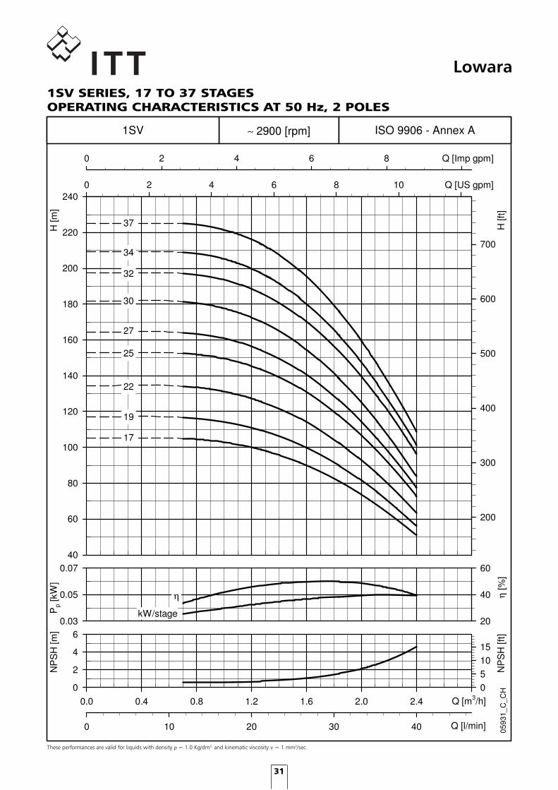
Lowara1SV SERIES, 17 TO 37 STAGES OPERATING CHARACTERISTICS AT 50 Hz, 2 POLES
These performances are valid for liquids with density � = 1.0 Kg/dm3 and kinematic viscosity � = 1 mm2/sec.
Pp
[kW
]
0.03
0.05
0.07
η [%
]
20
40
60
0.0 0.4 0.8 1.2 1.6 2.0 2.4 2.8
NP
SH
[m]
0
2
4
6
0 10 20 30 40
NP
SH
[ft]
05
1015
H [m
]
40
60
80
100
120
140
160
180
200
220
2400 2 4 6 8 10 12
H [f
t]
200
300
400
500
600
700
0 2 4 6 8 10
0593
1_C
_CH
ISO 9906 - Annex A
Q [US gpm]
Q [Imp gpm]
Q [l/min]
Q [m3/h]
∼ 2900 [rpm]
η
kW/stage
30
32
34
37
22
19
17
25
27
1SV
uk version eSV_UKLIT0047_EN bw version.indd 31 11/10/2010 11:14:46

32
Lowara3SV SERIESDIMENSIONS AND WEIGHTS AT 50 Hz, 2 POLES
DIMENSIONI E PESI SERIE 3SV 2 poli 50 Hz
PUMP
TYPE ELECTRIC
kW SIZE L1 1 ~ 3 ~ L3 L4 L5 L6 1 ~ 3 ~ 1 ~ 3 ~ D2 PUMP PUMP
3SV02 0,37 71 278 209 209 - - 253 253 111 111 120 120 105 8 12,83SV03 0,37 71 278 209 209 - - 253 253 111 111 120 120 105 8,4 13,23SV04 0,37 71 298 209 209 - - 273 273 111 111 120 120 105 8,8 13,63SV05 0,55 71 318 231 231 - - 293 293 121 121 140 140 105 9,2 143SV06 0,55 71 338 231 231 - - 313 313 121 121 140 140 105 9,7 16,43SV07 0,75 80 368 226 263 368 207 343 343 121 129 140 155 120 10,9 16,83SV08 0,75 80 388 226 263 388 227 363 363 121 129 140 155 120 11,3 21,93SV09 1,1 80 408 263 263 408 247 383 383 137 129 155 155 120 11,7 24,43SV10 1,1 80 428 263 263 428 267 403 403 137 129 155 155 120 12,1 24,83SV11 1,1 80 448 263 263 448 287 423 423 137 129 155 155 120 12,5 25,23SV12 1,1 80 468 263 263 468 307 443 443 137 129 155 155 120 13,3 25,63SV13 1,5 90 498 263 298 498 327 473 473 137 134 155 174 140 14 30,63SV14 1,5 90 518 263 298 518 347 493 493 137 134 155 174 140 14,4 313SV16 1,5 90 558 263 298 558 387 533 533 137 134 155 174 140 15,2 31,83SV19 2,2 90 618 298 298 618 447 593 593 151 134 174 174 140 16,4 34,43SV21 2,2 90 658 298 298 658 487 633 633 151 134 174 174 140 17,2 35,23SV23 2,2 90 698 298 298 698 527 - 673 151 134 174 174 140 18 363SV25 2,2 90 738 298 298 738 567 - 713 151 134 174 174 140 18,9 36,83SV27 3 100 788 - 298 788 607 - 763 - 134 - 174 160 20,7 42,63SV29 3 100 828 - 298 828 647 - 803 - 134 - 174 160 21,5 43,43SV31 3 100 868 - 298 868 687 - 843 - 134 - 174 160 22,3 44,23SV33 3 100 908 - 298 908 727 - 883 - 134 - 174 160 23,1 45
3sv-2p50-en_a_td
MOTOR WEIGHT kg
D1
DIMENSIONS (mm)
M L2
uk version eSV_UKLIT0047_EN bw version.indd 32 11/10/2010 11:14:48

33
Lowara
These performances are valid for liquids with density � = 1.0 Kg/dm3 and kinematic viscosity � = 1 mm2/sec.
Pp
[kW
]
0.04
0.08
0.12
η [%
]
30
50
70
0 1 2 3 4 5
NP
SH
[m]
0
2
4
6
0 10 20 30 40 50 60 70 80
NP
SH
[ft]
05
1015
H [m
]
0
20
40
60
80
100
120
140
160
180
200
220
240
2600 5 10 15 20
H [f
t]
0
100
200
300
400
500
600
700
800
0 5 10 15
0593
2_C
_CH
ISO 9906 - Annex A
Q [US gpm]
Q [Imp gpm]
Q [l/min]
Q [m3/h]
∼ 2900 [rpm]
η
14
1211
10
16
kW/stage
19
21
23
25
27
29
31
33
13
3SV
05
0203
04
0607
0809
3SV SERIES OPERATING CHARACTERISTICS AT 50 Hz, 2 POLES
uk version eSV_UKLIT0047_EN bw version.indd 33 11/10/2010 11:14:48

34
Lowara5SV SERIESDIMENSIONS AND WEIGHTS AT 50 Hz, 2 POLES
DIMENSIONI E PESI SERIE 5SV 2 poli 50 Hz
PUMP
TYPE ELECTRIC
kW SIZE L1 1 ~ 3 ~ L3 L4 L5 L6 1 ~ 3 ~ 1 ~ 3 ~ D2 PUMP PUMP
5SV02 0,37 71 268 209 209 - - 243 243 111 111 120 120 105 8,4 13,25SV03 0,55 71 293 231 231 - - 268 268 121 121 140 140 105 8,9 15,75SV04 0,55 71 318 231 231 - - 293 293 121 121 140 140 105 9,4 16,15SV05 0,75 80 353 226 263 - - 328 328 121 129 140 155 120 10,5 21,55SV06 1,1 80 378 263 263 - - 353 353 137 129 155 155 120 11 23,65SV07 1,1 80 403 263 263 403 242 378 378 137 129 155 155 120 11,5 245SV08 1,1 80 428 263 263 428 267 403 403 137 129 155 155 120 12,1 24,55SV09 1,5 90 463 263 298 463 292 438 438 137 134 155 174 140 12,7 30,95SV10 1,5 90 488 263 298 488 317 463 463 137 134 155 174 140 13,1 31,35SV11 1,5 90 513 263 298 513 342 488 488 137 134 155 174 140 13,6 31,85SV12 2,2 90 538 298 298 538 367 513 513 151 134 174 174 140 14,1 32,35SV13 2,2 90 563 298 298 563 392 538 538 151 134 174 174 140 14,6 32,85SV14 2,2 90 588 298 298 588 417 563 563 151 134 174 174 140 15 33,25SV15 2,2 90 613 298 298 613 442 588 588 151 134 174 174 140 15,5 33,75SV16 2,2 90 638 298 298 638 467 613 613 151 134 174 174 140 16 34,25SV18 3 100 698 - 298 698 517 673 673 - 134 - 174 160 18 395SV21 3 100 773 - 298 773 592 748 748 - 134 - 174 160 19,4 40,45SV23 4 112 823 - 319 823 642 - 798 - 154 - 197 160 20,4 475SV25 4 112 873 - 319 873 692 - 848 - 154 - 197 160 21,3 485SV28 4 112 948 - 319 948 767 - 923 - 154 - 197 160 23 49,45SV30 5,5 132 1018 - 375 1018 817 - 993 - 168 - 214 300 28,1 65,75SV33 5,5 132 1093 - 375 1093 892 - 1068 - 168 - 214 300 29,5 67,1
5sv-2p50-en_a_td
MOTOR WEIGHT kg
D1
DIMENSIONS (mm)
M L2
uk version eSV_UKLIT0047_EN bw version.indd 34 11/10/2010 11:14:50

35
Lowara
These performances are valid for liquids with density � = 1.0 Kg/dm3 and kinematic viscosity � = 1 mm2/sec.
Pp
[kW
]
0.05
0.10
0.15
0.20
η [%
]
20
40
60
80
0 1 2 3 4 5 6 7 8 9 10
NP
SH
[m]
1
2
3
0 20 40 60 80 100 120 140 160
NP
SH
[ft]
4
6
8
H [m
]
0
20
40
60
80
100
120
140
160
180
200
220
240
2600 5 10 15 20 25 30 35 40
H [f
t]
0
100
200
300
400
500
600
700
800
0 5 10 15 20 25 30 35
0593
4_B
_CH
ISO 9906 - Annex A
Q [US gpm]
Q [Imp gpm]
Q [l/min]
Q [m3/h]
∼ 2900 [rpm]
η
1413
1211
10
1516
kW/stage
18
21
23
25
28
30
33
5SV
0203
0405
0607
0809
5SV SERIES OPERATING CHARACTERISTICS AT 50 Hz, 2 POLES
uk version eSV_UKLIT0047_EN bw version.indd 35 11/10/2010 11:14:51

36
Lowara10SV SERIESDIMENSIONS AND WEIGHTS AT 50 Hz, 2 POLES
DIMENSIONI E PESI SERIE 10SV 2 poli 50 Hz
PUMP
TYPE ELECTRIC
kW SIZE L1 1 ~ 3 ~ L3 L4 L5 L6 1 ~ 3 ~ 1 ~ 3 ~ D2 PUMP PUMP
10SV01 0,75 80 357 226 263 - - 357 367 121 129 140 155 120 14,2 25,4
10SV02 0,75 80 357 226 263 - - 357 367 121 129 140 155 120 15,1 26,3
10SV03 1,1 80 389 263 263 - - 389 399 137 129 155 155 120 16,1 29
10SV04 1,5 90 431 263 298 - - 431 441 137 134 155 174 140 17,6 33,8
10SV05 2,2 90 463 298 298 463 259 463 473 151 134 174 174 140 18,5 36,7
10SV06 2,2 90 495 298 298 495 291 495 505 151 134 174 174 140 19,7 37,9
10SV07 3 100 537 - 298 537 323 537 547 - 134 - 174 160 21,5 42,5
10SV08 3 100 569 - 298 569 355 569 579 - 134 - 174 160 22,4 43,4
10SV09 4 112 601 - 319 601 387 601 611 - 154 - 197 160 23,3 49,7
10SV10 4 112 633 - 319 633 419 633 643 - 154 - 197 160 24,3 50,7
10SV11 4 112 665 - 319 665 451 665 675 - 154 - 197 160 25,2 52
10SV13 5,5 132 796 - 375 796 515 796 806 - 168 - 214 300 33,1 71
10SV15 5,5 132 860 - 375 860 579 - 870 - 168 - 214 300 35 73
10SV17 7,5 132 924 - 367 924 643 - 934 - 191 - 256 300 36,9 93
10SV18 7,5 132 956 - 367 956 675 - 966 - 191 - 256 300 37,8 94
10SV20 7,5 132 1020 - 367 1020 739 - 1030 - 191 - 256 300 39,6 96
10SV21 11 160 1082 - 428 1082 771 - 1092 - 191 - 256 350 42,2 113
10sv-2p50-en_a_td
MOTOR WEIGHT kg
D1
DIMENSIONS (mm)
M L2
uk version eSV_UKLIT0047_EN bw version.indd 36 11/10/2010 11:14:53

37
Lowara10SV SERIESOPERATING CHARACTERISTICS AT 50 Hz, 2 POLES
These performances are valid for liquids with density � = 1.0 Kg/dm3 and kinematic viscosity � = 1 mm2/sec.
Pp
[kW
]
0.2
0.4
0.6
η [%
]
40
60
80
0 2 4 6 8 10 12 14 16
NP
SH
[m]
1
2
3
0 50 100 150 200 250
NP
SH
[ft]
4
6
8
H [m
]
0
20
40
60
80
100
120
140
160
180
200
220
240
2600 10 20 30 40 50 60 70
H [f
t]
0
100
200
300
400
500
600
700
800
0 10 20 30 40 50
0593
6_C
_CH
ISO 9906 - Annex A
Q [US gpm]
Q [Imp gpm]
Q [l/min]
Q [m3/h]
∼ 2900 [rpm]
η
10
18
kW/stage
21
10SV
11
13
15
17
20
01
02
03
04
05
06
07
08
09
uk version eSV_UKLIT0047_EN bw version.indd 37 11/10/2010 11:14:53

38
Lowara15SV SERIESDIMENSIONS AND WEIGHTS AT 50 Hz, 2 POLES
DIMENSIONI E PESI SERIE 15SV 2 poli 50 Hz
PUMP
TYPE ELECTRIC
kW SIZE L1 1 ~ 3 ~ L3 L4 L5 1 ~ 3 ~ 1 ~ 3 ~ D2 PUMP PUMP
15SV01 1,1 80 399 263 263 - - 399 137 129 155 155 120 15 28,2
15SV02 2,2 90 409 298 298 - - 409 151 134 174 174 140 16,8 34,7
15SV03 3 100 467 - 298 - - 467 - 134 - 174 160 19 40
15SV04 4 112 515 - 319 515 301 515 - 154 - 197 160 20,3 46,8
15SV05 4 112 563 - 319 563 349 563 - 154 - 197 160 21,5 47,9
15SV06 5,5 132 678 - 375 678 397 678 - 168 - 214 300 28,9 67
15SV07 5,5 132 726 - 375 726 445 726 - 168 - 214 300 30,2 68
15SV08 7,5 132 774 - 367 774 493 774 - 191 - 256 300 31,5 88
15SV09 7,5 132 822 - 367 822 541 822 - 191 - 256 300 32,8 90
15SV10 11 160 900 - 428 900 589 900 - 191 - 256 350 37 108
15SV11 11 160 948 - 428 948 637 - - 191 - 256 350 38,3 109
15SV13 11 160 1044 - 428 1044 733 - - 191 - 256 350 41 112
15SV15 15 160 1140 - 494 1140 829 - - 240 - 313 350 43,7 146
15SV17 15 160 1236 - 494 1236 925 - - 240 - 313 350 46,7 149
15sv-2p50_a_td
MOTOR WEIGHT kg
D1
DIMENSIONS (mm)
M L2
uk version eSV_UKLIT0047_EN bw version.indd 38 11/10/2010 11:14:56

39
Lowara15SV SERIESOPERATING CHARACTERISTICS AT 50 Hz, 2 POLES
These performances are valid for liquids with density � = 1.0 Kg/dm3 and kinematic viscosity � = 1 mm2/sec.
Pp
[kW
]
0.4
0.8
1.2
η [%
]
40
60
80
0 2 4 6 8 10 12 14 16 18 20 22 24 26 28
NP
SH
[m]
0
2
4
0 100 200 300 400
NP
SH
[ft]
0
4
8
12
H [m
]
0
20
40
60
80
100
120
140
160
180
200
220
240
2600 20 40 60 80 100 120
H [f
t]
0
100
200
300
400
500
600
700
800
0 20 40 60 80 100
0593
7_C
_CH
ISO 9906 - Annex A
Q [US gpm]
Q [Imp gpm]
Q [l/min]
Q [m3/h]
∼ 2900 [rpm]
η
kW/stage
13
15
17
11
10
15SV
01
02
03
04
05
06
07
08
09
uk version eSV_UKLIT0047_EN bw version.indd 39 11/10/2010 11:14:56

40
Lowara22SV SERIESDIMENSIONS AND WEIGHTS AT 50 Hz, 2 POLES
DIMENSIONI E PESI SERIE 22SV 2 poli 50 Hz
PUMP
TYPE ELECTRIC
kW SIZE L1 1 ~ 3 ~ L3 L4 L5 1 ~ 3 ~ 1 ~ 3 ~ D2 PUMP PUMP
22SV01 1,1 80 399 263 263 - - 399 137 129 155 155 120 15,5 28,3
22SV02 2,2 90 409 298 298 - - 409 151 134 174 174 140 17,2 35,4
22SV03 3 100 467 - 298 - - 467 - 134 - 174 160 19,4 40,4
22SV04 4 112 515 - 319 515 301 515 - 154 - 197 160 20,7 47,1
22SV05 5,5 132 630 - 375 630 349 630 - 168 - 214 300 26,7 65
22SV06 7,5 132 678 - 367 678 397 678 - 191 - 256 300 28 84
22SV07 7,5 132 726 - 367 726 445 726 - 191 - 256 300 29,3 86
22SV08 11 160 804 - 428 804 493 804 - 191 - 256 350 33,1 104
22SV09 11 160 852 - 428 852 541 852 - 191 - 256 350 34,4 105
22SV10 11 160 900 - 428 900 589 900 - 191 - 256 350 35,8 107
22SV12 15 160 996 - 494 996 685 - - 240 - 313 350 38,4 141
22SV14 15 160 1092 - 494 1092 781 - - 240 - 313 350 41,1 144
22SV17 18,5 160 1236 - 494 1236 925 - - 240 - 313 350 45,1 156
22sv-2p50-en_a_td
MOTOR WEIGHT kg
D1
DIMENSIONS (mm)
M L2
uk version eSV_UKLIT0047_EN bw version.indd 40 11/10/2010 11:14:58

41
Lowara22SV SERIESOPERATING CHARACTERISTICS AT 50 Hz, 2 POLES
These performances are valid for liquids with density � = 1.0 Kg/dm3 and kinematic viscosity � = 1 mm2/sec.
Pp
[kW
]
0.6
1.0
1.4
η [%
]
40
60
80
0 5 10 15 20 25 30 35
NP
SH
[m]
0
2
4
6
0 100 200 300 400 500
NP
SH
[ft]
0481216
H [m
]
0
20
40
60
80
100
120
140
160
180
200
220
240
260
2800 20 40 60 80 100 120 140
H [f
t]
0
100
200
300
400
500
600
700
800
900
0 20 40 60 80 100 120
0593
8_D
_CH
ISO 9906 - Annex A
Q [US gpm]
Q [Imp gpm]
Q [l/min]
Q [m3/h]
∼ 2900 [rpm]
η
14
12
10
kW/stage
17
22SV
01
02
03
04
05
06
07
08
09
uk version eSV_UKLIT0047_EN bw version.indd 41 11/10/2010 11:14:58

42
LowaraSV33 SERIESDIMENSIONS AND WEIGHTS AT 50 Hz, 2 POLES
F version: AISI 316/Cast iron, in-line ports, round flanges
N version: AISI 316, in-line ports, round flanges
uk version eSV_UKLIT0047_EN bw version.indd 42 11/10/2010 11:15:00

43
LowaraSV33 SERIESOPERATING CHARACTERISTICS AT 50 Hz, 2 POLES
These performances are valid for liquids with density � = 1.0 Kg/dm3 and kinematic viscosity � = 1 mm2/sec.
uk version eSV_UKLIT0047_EN bw version.indd 43 11/10/2010 11:15:00

44
LowaraSV46 SERIESDIMENSIONS AND WEIGHTS AT 50 Hz, 2 POLES
F version: AISI 316/Cast iron, in-line ports, round flanges
N version: AISI 316, in-line ports, round flanges
uk version eSV_UKLIT0047_EN bw version.indd 44 11/10/2010 11:15:00

45
LowaraSV46 SERIESOPERATING CHARACTERISTICS AT 50 Hz, 2 POLES
These performances are valid for liquids with density � = 1.0 Kg/dm3 and kinematic viscosity � = 1 mm2/sec.
uk version eSV_UKLIT0047_EN bw version.indd 45 11/10/2010 11:15:01

46
LowaraSV66 SERIESDIMENSIONS AND WEIGHTS AT 50 Hz, 2 POLES
F version: AISI 316/Cast iron, in-line ports, round flanges
N version: AISI 316, in-line ports, round flanges
uk version eSV_UKLIT0047_EN bw version.indd 46 11/10/2010 11:15:01

47
LowaraSV66 SERIESOPERATING CHARACTERISTICS AT 50 Hz, 2 POLES
These performances are valid for liquids with density � = 1.0 Kg/dm3 and kinematic viscosity � = 1 mm2/sec.
uk version eSV_UKLIT0047_EN bw version.indd 47 11/10/2010 11:15:02

48
LowaraSV92 SERIESDIMENSIONS AND WEIGHTS AT 50 Hz, 2 POLES
F version: AISI 316/Cast iron, in-line ports, round flanges
N version: AISI 316, in-line ports, round flanges
uk version eSV_UKLIT0047_EN bw version.indd 48 11/10/2010 11:15:02

49
LowaraSV92 SERIESOPERATING CHARACTERISTICS AT 50 Hz, 2 POLES
These performances are valid for liquids with density � = 1.0 Kg/dm3 and kinematic viscosity � = 1 mm2/sec.
uk version eSV_UKLIT0047_EN bw version.indd 49 11/10/2010 11:15:03

50
Lowara125SV SERIESDIMENSIONS AND WEIGHTS AT 50 Hz, 2 POLES
DIMENSIONI E PESI SERIE 125SV 2 poli 50 Hz
PUMP
TYPE FLANGES ELECTRIC
kW SIZE L1 L2 D1 D2 M PN PUMP PUMP
125SV1 7,5 132 693 367 256 300 191 16 116 172125SV2 15 160 878 494 313 350 240 16 131 233125SV3 22 180 1028 494 313 350 240 16 143 265125SV4 30 200 1178 657 402 400 317 16 161 388125SV5 37 200 1328 657 402 400 317 16 172 428125SV6 45 225 1478 746 455 450 384 16 187 544125SV7 55 250 1658 825 486 550 402 25 216 630125SV8/2A 55 250 1808 825 486 550 402 25 229 643
125sv-2p50-en_a_td
MOTOR DIMENSIONS (mm) WEIGHT kg
uk version eSV_UKLIT0047_EN bw version.indd 50 11/10/2010 11:15:03

51
Lowara
These performances are valid for liquids with density � = 1.0 Kg/dm3 and kinematic viscosity � = 1 mm2/sec.
Pp
[kW
]
45678
η [%
]
4050607080
0 20 40 60 80 100 120 140 160 180
NP
SH
[m]
0
4
8
12
0 500 1000 1500 2000 2500 3000
NP
SH
[ft]
010
2030
H [m
]
0
20
40
60
80
100
120
140
160
180
200
2200 100 200 300 400 500 600 700
H [f
t]
0
100
200
300
400
500
600
700
0 100 200 300 400 500 600
0593
9_B
_CH
ISO 9906 - Annex A
Q [US gpm]
Q [Imp gpm]
Q [l/min]
Q [m3/h]
∼ 2900 [rpm]
4
6
kW/stage
1
3
2
5
7
125SV
P2 1P2 /1A
η
8/2A
125SV SERIESOPERATING CHARACTERISTICS AT 50 Hz, 2 POLES
uk version eSV_UKLIT0047_EN bw version.indd 51 11/10/2010 11:15:03

52
LowaraSV2 to 3SV REPLACEMENT GUIDE
3SV-4 -0.37kWSV203 -0.37kW
SV204 -0.55kW
3SV-8 -0.75kW
3SV-12 -1.1kW
SV209 -1.1kW
3SV-16 -1.5kWSV212 -1.5kW
3SV-25 -2.2kW
SV224 -3kW
SV218 -2.2kW
3SV-6 -0.55kW
SV206 -0.75kW
3SV-33 -3kW
0 10 20 30 40 50 60 70 80 90
Q [l/min]
0
50
100
150
200
2500 1 2 3 4 5
Q [m3/h]
H [m
]
- SV2 - 50Hz- 3SV - 50Hz
For other curve information please see SV 2-16 technical catalogue at www.lowara.co.uk
uk version eSV_UKLIT0047_EN bw version.indd 52 11/10/2010 11:15:05

53
LowaraSV2 to 3SV REPLACEMENT GUIDE
Current SV Model
Nominal Power [kW]
Q max [m3/h]
H (BEP @ 3m3/h)
[m]
H max [m]
L1 [mm] L2 [mm] L1+L2 [mm]
e-SV Model
Nominal Power [kW]
Q max [m3/h]
H (BEP @ 3m3/h)
[m]
H max [m]
L1 [mm] L2 [mm] L1+L2 [mm]
SV202 0.37 4.2 13 21.5 285 209 494 3SV03 0.37 4.4 17 22 278 209 487SV203 0.37 4.2 19 32 310 209 519 3SV04 0.37 4.4 21 29 298 209 507
SV204 0.55 4.2 26 42.5 335 231 566 3SV05 0.55 4.4 30 38 318 231 549SV205 0.75 4.2 32 53.5 370 226 596 3SV06 0.55 4.4 35 44 338 231 569SV206 0.75 4.2 39 64 395 226 621 3SV07 0.75 4.4 42 52 368 263 631
SV207 1.1 4.2 45 75 420 263 683 3SV08 0.75 4.4 48 60 388 263 651
SV208 1.1 4.2 52 85.5 445 263 708 3SV09 1.1 4.4 55 68 408 263 671SV209 1.1 4.2 58 96 470 263 733 3SV10 1.1 4.4 60 76 428 263 691
SV211 1.5 4.2 71 117 530 263 793 3SV12 1.1 4.4 71 90 468 263 731SV212 1.5 4.2 78 128 555 263 818 3SV13 1.5 4.4 79 98 498 298 796
SV214 2.2 4.2 90 150 605 263 868 3SV16 1.5 4.4 96 120 558 298 856SV216 2.2 4.2 103 171 655 263 918SV218 2.2 4.2 116 192 705 263 968
SV220 3 4.2 129 214 765 298 1063 3SV21 2.2 4.4 128 160 658 298 956SV222 3 4.2 142 235 815 298 1113 3SV25 2.2 4.4 150 189 738 298 1036SV224 3 4.2 155 256 865 298 1163 3SV27 3 4.4 163 205 788 298 1086
3SV19 2.2 4.4 916117 145 618 298
Existing SV2 in-line F, T and N versions have the same face-to-face dimensions asthe new 3SV series F, T and N respective versions.
Please Note:The replacement table guide above is basedupon the equivalent duty at the bestefficiency point on the operating curve, forother specific duties or application types adifferent selection maybe more appropriate -please see overlay curves on opposite page.
uk version eSV_UKLIT0047_EN bw version.indd 53 11/10/2010 11:15:06

54
LowaraSV4 to 5SV REPLACEMENT GUIDE
5SV03-0.37kWSV402-0.37kW
5SV04-0.55kWSV403-0.55kW
5SV05-0.75kWSV404-0.75kW
5SV08-1.1kW
SV407-1.1kW
5SV11-1.5kWSV409-1.5kW
5SV16-2.2kW
SV413-2.2kW
5SV21-3kW
SV418-3kW
5SV28-4kW
SV424-4kW
0 20 40 60 80 100 120 140 160
Q [l/min]
0
50
100
150
200
2500 1 2 3 4 5 6 7 8 9
Q [m3/h]
H [m
]
- SV4 - 50Hz- 5SV - 50Hz
For other curve information please see SV 2-16 technical catalogue at www.lowara.co.uk
uk version eSV_UKLIT0047_EN bw version.indd 54 11/10/2010 11:15:06

55
LowaraSV4 to 5SV REPLACEMENT GUIDE
Current SV Model
Nominal Power [kW]
Q max [m3/h]
H (BEP @
5,4m3/h) [m]
H max [m]
L1 [mm] L2 [mm] L1+L2 [mm]
e-SV Model
Nominal Power [kW]
Q max [m3/h]
H (BEP @
5,4m3/h) [m]
H max [m]
L1 [mm] L2 [mm] L1+L2 [mm]
SV402 0.37 8 12 20 285 209 494 5SV02 0.37 8.5 11 15 268 209 477SV403 0.55 8 17 30 310 231 541 5SV03 0.55 8.5 18 22 293 231 524SV404 0.75 8 23 40 345 226 571 5SV04 0.55 8.5 23 30 318 231 549
SV405 1.1 8 29 50 370 263 633 5SV05 0.75 8.5 30 38 353 263 616SV406 1.1 8 36 60 395 263 658 5SV06 1.1 8.5 36 45 378 263 641SV407 1.1 8 42 70 420 263 683 5SV07 1.1 8.5 42 53 403 263 666
SV408 1.5 8 47 80 455 263 718 5SV08 1.1 8.5 47 60 428 263 691SV409 1.5 8 54 90 480 263 743 5SV09 1.5 8.5 54 68 463 298 761
SV411 2.2 8 66 111 530 263 793 5SV11 1.5 8.5 65 82 513 298 811
SV413 2.2 8 77 131 580 263 843 5SV13 2.2 8.5 77 98 563 298 861SV414 3 8 83 141 615 298 913 5SV14 2.2 8.5 83 106 588 298 886SV416 3 8 95 161 665 298 963 5SV16 2.2 8.5 95 120 638 298 936
SV418 3 8 107 181 715 298 1013 5SV18 3 8.5 108 136 698 298 996SV420 4 8 118 201 765 319 1084 5SV21 3 8.5 123 158 773 298 1071SV422 4 8 130 221 815 319 1134 5SV23 4 8.5 138 175 823 319 1142SV424 4 8 142 241 865 319 1184 5SV25 4 8.5 149 190 873 319 1192
Existing SV4 in-line F, T and N versions have the same face-to-face dimensions asthe new 5SV series F, T and N respective versions.
Please Note:The replacement table guide above is basedupon the equivalent duty at the bestefficiency point on the operating curve, forother specific duties or application types adifferent selection maybe more appropriate -please see overlay curves on opposite page.
uk version eSV_UKLIT0047_EN bw version.indd 55 11/10/2010 11:15:07

56
LowaraSV8 to 10SV REPLACEMENT GUIDE
10SV01-0.75kW
SV802 -1.1kW
SV803 -1.5kW
10SV02-0.75kW
10SV03-1.1kW
SV805 -2.2kW
10SV04-1.5kW
SV806 -3kW
10SV06-2.2kW
10SV08-3kW
SV809 -4kW10SV11-4kW
10SV15-5.5kW
10SV20-7.5kW
SV812 -5.5kW
SV816 -7.5kW
10SV21-11kW
0 50 100 150 200 250
Q [l/min]
0
50
100
150
200
2500 2 4 6 8 10 12 14
Q [m3/h]
H [m
]
- SV8 - 50Hz- 10SV - 50Hz
For other curve information please see SV 2-16 technical catalogue at www.lowara.co.uk
uk version eSV_UKLIT0047_EN bw version.indd 56 11/10/2010 11:15:07

57
LowaraSV8 to 10SV REPLACEMENT GUIDE
Current SV Model
Nominal Power [kW]
Q max [m3/h]
H (BEP @
10m3/h) [m]
H max [m]
L1 [mm] L2 [mm] L1+L2 [mm]
e-SV Model
Nominal Power [kW]
Q max [m3/h]
H (BEP @
10m3/h) [m]
H max [m]
L1 [mm] L2 [mm] L1+L2 [mm]
SV802 1.1 14 21 27 363 263 626 10SV03 1.1 14 27 37 389 263 652SV803 1.5 14 31 41 411 263 674 10SV04 1.5 14 36 48 431 298 729SV804 2.2 14 42 55 449 263 712 10SV05 2.2 14 46 60 463 298 761SV805 2.2 14 52 68 487 263 750 10SV06 2.2 14 55 72 495 298 793SV806 3 14 63 82 535 298 833 10SV07 3 14 64 83 537 298 835
SV808 4 14 83 110 611 319 930 10SV09 4 14 84 109 601 319 920SV809 4 14 92 123 649 319 968 10SV10 4 14 92 120 633 319 952
SV811 5.5 14 112 150 745 375 1120 10SV13 5.5 14 119 157 796 375 1171SV812 5.5 14 123 164 783 375 1158 10SV15 5.5 14 136 180 860 375 1235SV814 7.5 14 144 192 859 367 1226 10SV17 7.5 14 159 205 924 367 1291SV816 7.5 14 164 220 935 367 1302 10SV18 7.5 14 168 218 956 367 1323
Existing SV8 in-line F, T and N versions have the same face-to-face dimensions asthe new 10SV series F, T and N respective versions.
Please Note:The replacement table guide above is basedupon the equivalent duty at the bestefficiency point on the operating curve, forother specific duties or application types adifferent selection maybe more appropriate -please see overlay curves on opposite page.
uk version eSV_UKLIT0047_EN bw version.indd 57 11/10/2010 11:15:07

58
LowaraSV16 to 15SV REPLACEMENT GUIDE
15SV01-1.1kW
SV1602-2.2kW
15SV02-2.2kW
SV1603-3kW
15SV03-3kW
SV1604-4kW15SV05-4kW
SV1606-5.5kW
15SV07-5.5kW
SV1608-7.5kW
15SV09-7.5kW
15SV13-11kW
SV1615-15kW15SV17-15kW
SV1612-11kW
0 50 100 150 200 250 300 350 400 450
Q [l/min]
0
50
100
150
200
2500 5 10 15 20 25
Q [m3/h]
H [m
]
- SV16 - 50Hz - 15SV - 50Hz
For other curve information please see SV 2-16 technical catalogue at www.lowara.co.uk
uk version eSV_UKLIT0047_EN bw version.indd 58 11/10/2010 11:15:08

59
LowaraSV16 to 15SV REPLACEMENT GUIDE
Current SV Model
Nominal Power [kW]
Q max [m3/h]
H (BEP @
16m3/h) [m]
H max [m]
L1 [mm] L2 [mm] L1+L2 [mm]
e-SV Model
Nominal Power [kW]
Q max [m3/h]
H (BEP @
16m3/h) [m]
H max [m]
L1 [mm] L2 [mm] L1+L2 [mm]
SV1602 2.2 24 28 35 383 263 646 15SV03 3 24 35 43 467 298 765SV1603 3 24 41 52 431 298 729 15SV04 4 24 47 58 515 319 834SV1604 4 24 55 69 469 319 788 15SV05 4 24 58 72 563 319 882SV1605 5.5 24 68 86 527 375 902 15SV06 5.5 24 73 90 678 375 1053SV1606 5.5 24 83 104 565 375 940 15SV07 5.5 24 84 103 726 375 1101SV1607 7.5 24 96 121 603 367 970 15SV08 7.5 24 98 120 774 367 1141SV1608 7.5 24 109 138 641 367 1008 15SV09 7.5 24 110 135 822 367 1189
SV1610 11 24 137 173 749 428 1177 15SV11 11 24 137 165 948 428 1376SV1612 11 24 165 207 825 428 1253 15SV13 11 24 161 195 1140 428 1568SV1614 15 24 192 242 901 494 1395SV1615 15 24 205 260 939 494 1433
1730209 252 1236 49415SV17 15 24
Existing SV16 in-line F, T and N versions have the same face-to-face dimensions asthe new 15SV series F, T and N respective versions.
Please Note:The replacement table guide above is basedupon the equivalent duty at the bestefficiency point on the operating curve, forother specific duties or application types adifferent selection maybe more appropriate -please see overlay curves on opposite page.
uk version eSV_UKLIT0047_EN bw version.indd 59 11/10/2010 11:15:08

60
Lowara
Dimensions of counterflanges .........................................................................................................61
Dimensions of Victaulic®, Clamp couplings ....................................................................................62
ACCESSORIES
uk version eSV_UKLIT0047_EN bw version.indd 60 11/10/2010 11:15:09

61
LowaraDIMENSIONS OF OVAL COUNTERFLANGES (T SV)
DIMENSIONS OF ROUND THREADED COUNTERFLANGES (F, N, R SV) ACCORDING TO EN 1092-1
DIMENSIONS OF WELD-ON ROUND COUNTERFLANGES (G, N SV) ACCORDING TO EN 1092-1
DIMENSIONI CONTROFLANGE OVALI per 1-2
PUMP
TYPE DN ø C A B D H ø F N° PN
1-3SVT 25 Rp 1 75 12 100 22 11 2 16
5SVT 32 Rp 1¼ 75 12 100 22 11 2 16
10SVT 40 Rp 1½ 100 15 132 25 14 2 16
15-22SVT 50 Rp 2 100 15 132 25 14 2 161-22sv-ctf-ovali-en_a_td
DIMENSIONS (mm) HOLES
DIMENSIONI CONTROFLANGE TONDE FILETT
PUMP
TYPE DN ø C ø A B ø D H ø F N° PN
1-3SV 25 Rp 1 85 10 115 16 14 4 25
5SV 32 Rp 1¼ 100 13 140 16 18 4 25
10SV 40 Rp 1½ 110 14 150 19 18 4 25
15-22SV 50 Rp 2 125 16 165 24 18 4 25 1-22sv-ctf-tonde-f-en_a_td
DIMENSIONS (mm) HOLES
DIMENSIONI CONTROFLANGE TONDE A SA
PUMP
TYPE DN ø C ø A B ø D ø F N° PN
125SV 125 141 210 24 250 18 8 16
125SV 125 141 220 28 270 25 8 25-40 125sv-ctf-tonde-s-en_a_td
DIMENSIONS (mm) HOLES
Round counterflanges Kit available on request: Kit containing 2 counterflanges with bolts and gaskets.- 1, 3, 5, 10, 15, 22SV F, R versions : threaded, galvanized steel.- 1, 3, 5, 10, 15, 22SV N versions : threaded, AISI 316L stainless steel.
Standard supply (included with the pump)- AISI 304L stainless steel.
Round counterflanges Kit available on request:Kit containing 2 counterflanges with bolts and gaskets.- 125SV G versions : weld-on counterflanges, galvanized steel.- 125SV N versions : weld-on counterflanges, AISI 316L stainless steel.
DIMENSIONS OF WELD-ON ROUND FLANGES (SV VERSIONS F, N)
uk version eSV_UKLIT0047_EN bw version.indd 61 11/10/2010 11:15:09

62
LowaraDIMENSIONS OF VICTAULIC® COUPLINGS (V SV)
DIMENSIONS OF CLAMP COUPLINGS (C SV)
DIMENSIONI GIUNTI VICTAULIC SV2
PUMP
TYPE ø D4 ø D5 M
1-3-5SV V R 1¼ 42,2 320
10-15-22SV V R 2 60,3 378 1-22sv-giunti-vict-en_a_td
DIMENSIONS (mm)
WELD-ON SLEEVES THREADED SLEEVES
WELD-ON SLEEVES THREADED SLEEVES
Victaulic® couplings kit available on request: Kit containing 1 Victaulic® coupling with AISI 316L stainless steel weld-on or threaded sleeve, plus EPDM or FPM gasket.
OTHER ACCESSORIES:- Dry running sensor Optical sensor for detecting the lack of water in order to prevent damage deriving from dry running. This accessory can be applied at the filling tap. - i-ALERT™ Patented i-ALERT™ monitor continuously measures vibration to support optimum performance. Available on pumps 7,5 kW (10 HP) and above.
DIMENSIONI GIUNTI CLAMP 1-22 SV
PUMP
TYPE A B ø D6 ø D7
1-3-5SV C 208 245 35 Rp 1¼
10-15-22SV C 248 301 53 Rp 2 1-22sv-giunti-clamp-en_a_td
DIMENSIONS (mm)
Clamp couplings kit available on request: Kit containing 2 Clamp couplings with AISI 316L stainless steel weld-on or threaded sleeve, plus EPDM or FPM gasket. Coupling shape and dimensions according to DIN 32676.
uk version eSV_UKLIT0047_EN bw version.indd 62 11/10/2010 11:15:10

63
LowaraSPECIAL VERSIONS ON REQUEST
More and more customers require specific solutions for satisfying particular application requirements. To meet their needs, Lowara offers a series of variants for personalising the e-SV pumps.
� High pressure pump: the SV pump was especially designed to withstand maximum operating pressures of 40 bar. In case of elevated input pressures, it can be used as a single pump or in a system with 2 pumps connected in series and reach heads of over 400 metres.
� Horizontal version: the SV pump is supplied with motor and pump support brackets for specific applications requiring horizontal assembly.
� Version with low NPSH: the SV pump was especially designed for boiler charging applications with an elevated risk of cavitation.
� High temperature version: the SV pump was especially developed to operate with water at high temperatures (up to 150°C).
� Clean & Dry version: the SV pump is produced with specific modifications for applications requiring elevated levels of hygiene.
� Passivated and electro-polished version: all SV pump components are passivated and electro-polished in order to reduce the risk of corrosion and to comply with specific hygiene requirements.
� Version with stainless steel base: the SV pump can be supplied with a stainless steel base for applications in aggressive conditions.
� Motors: - Standard 4-pole motor. - Motor with anti-condensate option for applications in damp conditions. - Motor with overheating protection incorporating bimetallic thermal switches or PTC sensors. - ATEX motor for operating in explosive atmospheres. - The direction of the motor terminal block can be adjusted. - Motor protected to IP65.
� Elastomers: as well as the EPDM elastomers used in the standard version, other materials are available to satisfy specific customer requirements.
uk version eSV_UKLIT0047_EN bw version.indd 63 11/10/2010 11:15:11

64
Lowara
TECHNICALAPPENDIX
uk version eSV_UKLIT0047_EN bw version.indd 64 11/10/2010 11:15:11

65
Lowara
TECHNICAL APPENDIX
The minimum operating values that can be reached at the pump suction end are limited by the onset of cavitation.
Cavitation is the formation of vapour-filled cavities within liquids where the pressure is locally reduced to a critical value, or where the local pressure is equal to, or just below the vapour pressure of the liquid.
The vapour-filled cavities flow with the current andwhen they reach a higher pressure area the vapourcontained in the cavities condenses. The cavities collide,generating pressure waves that are transmitted to thewalls. These, being subjected to stress cycles, graduallybecome deformed and yield due to fatigue. Thisphenomenon, characterized by a metallic noiseproduced by the hammering on the pipe walls, is calledincipient cavitation. The damage caused by cavitation may be magnified byelectrochemical corrosion and a local rise intemperature due to the plastic deformation of thewalls. The materials that offer the highest resistance toheat and corrosion are alloy steels, especially austeniticsteel. The conditions that trigger cavitation may beassessed by calculating the total net suction head,referred to in technical literature with the acronymNPSH (Net Positive Suction Head).
The NPSH represents the total energy (expressed in m.)of the liquid measured at suction under conditions ofincipient cavitation, excluding the vapour pressure(expressed in m.) that the liquid has at the pump inlet.
To find the static height hz at which to install themachine under safe conditions, the following formulamust be verified:
hp + hz � (NPSHr + 0.5) + hf + hpv
where:hp is the absolute pressure applied to the free liquid surface in the suction tank, expressed in m. of liquid; hp is the quotient between the barometric pressure and the specific weight of the liquid.hz is the suction lift between the pump axis and the free liquid surface in the suction tank, expressed in m.; hz is negative when the liquid level is lower than the pump axis.hf is the flow resistance in the suction line and its accessories, such as: fittings, foot valve, gate valve, elbows, etc.hpv is the vapour pressure of the liquid at the operating temperature, expressed in m. of liquid. hpv is the quotient between the Pv vapour pressure and the liquid’s specific weight.0,5 is the safety factor.
The maximum possible suction head for installationdepends on the value of the atmospheric pressure(i.e. the elevation above sea level at which the pumpis installed) and the temperature of the liquid.
To help the user, with reference to water temperature(4° C) and to the elevation above sea level, thefollowing tables show the drop in hydraulic pressurehead in relation to the elevation above sea level, andthe suction loss in relation to temperature.
Friction loss is shown in the tables at pages 48-49 ofthis catalogue. To reduce it to a minimum, especiallyin cases of high suction head (over 4-5 m.) or withinthe operating limits with high flow rates, werecommend using a suction line having a largerdiameter than that of the pump’s suction port.It is always a good idea to position the pump as closeas possible to the liquid to be pumped.
Make the following calculation:
Liquid: water at ~15°C � = 1 kg/dm3
Flow rate required: 30 m3/hHead for required delivery: 43 m.Suction lift: 3,5 m.The selection is an FHE 40-200/75 pump whose NPSHrequired value is, at 30 m3/h, di 2,5 m.
For water at 15 °C
hp = Pa /�� = 10,33m, hpv = Pv / � = 0,174m (0,01701 bar)
The Hf flow resistance in the suction line with footvalves is ~ 1,2 m.By substituting the parameters in formula with thenumeric values above, we have:
10,33 + (-3,5) � (2,5 + 0,5) + 1,2 + 0,17
from which we have: 6,8 > 4,4
The relation is therefore verified.
Water temperature (°C) 20 40 60 80 90 110 120
Suction loss (m) 0,2 0,7 2,0 5,0 7,4 15,4 21,5
Elevation above sea level (m) 500 1000 1500 2000 2500 3000
Suction loss (m) 0,55 1,1 1,65 2,2 2,75 3,3
NPSH
1
1
uk version eSV_UKLIT0047_EN bw version.indd 65 11/10/2010 11:15:11

66
Lowara
TECHNICAL APPENDIX
t T ps ρ ρ ρt T ps t T ps
°C K bar kg/dm3 °C K bar kg/dm3 °C K bar kg/dm3
0 273,15 0,00611 0,9998 55 328,15 0,15741 0,9857 120 393,15 1,9854 0,94291 274,15 0,00657 0,9999 56 329,15 0,16511 0,9852 122 395,15 2,1145 0,94122 275,15 0,00706 0,9999 57 330,15 0,17313 0,9846 124 397,15 2,2504 0,93963 276,15 0,00758 0,9999 58 331,15 0,18147 0,9842 126 399,15 2,3933 0,93794 277,15 0,00813 1,0000 59 332,15 0,19016 0,9837 128 401,15 2,5435 0,93625 278,15 0,00872 1,0000 60 333,15 0,1992 0,9832 130 403,15 2,7013 0,93466 279,15 0,00935 1,0000 61 334,15 0,2086 0,9826 132 405,15 2,867 0,93287 280,15 0,01001 0,9999 62 335,15 0,2184 0,9821 134 407,15 3,041 0,93118 281,15 0,01072 0,9999 63 336,15 0,2286 0,9816 136 409,15 3,223 0,92949 282,15 0,01147 0,9998 64 337,15 0,2391 0,9811 138 411,15 3,414 0,9276
10 283,15 0,01227 0,9997 65 338,15 0,2501 0,9805 140 413,15 3,614 0,925811 284,15 0,01312 0,9997 66 339,15 0,2615 0,9799 145 418,15 4,155 0,921412 285,15 0,01401 0,9996 67 340,15 0,2733 0,9793 155 428,15 5,433 0,912113 286,15 0,01497 0,9994 68 341,15 0,2856 0,9788 160 433,15 6,181 0,907314 287,15 0,01597 0,9993 69 342,15 0,2984 0,9782 165 438,15 7,008 0,902415 288,15 0,01704 0,9992 70 343,15 0,3116 0,9777 170 433,15 7,920 0,897316 289,15 0,01817 0,9990 71 344,15 0,3253 0,9770 175 448,15 8,924 0,892117 290,15 0,01936 0,9988 72 345,15 0,3396 0,9765 180 453,15 10,027 0,886918 291,15 0,02062 0,9987 73 346,15 0,3543 0,9760 185 458,15 11,233 0,881519 292,15 0,02196 0,9985 74 347,15 0,3696 0,9753 190 463,15 12,551 0,876020 293,15 0,02337 0,9983 75 348,15 0,3855 0,9748 195 468,15 13,987 0,870421 294,15 0,24850 0,9981 76 349,15 0,4019 0,9741 200 473,15 15,550 0,864722 295,15 0,02642 0,9978 77 350,15 0,4189 0,9735 205 478,15 17,243 0,858823 296,15 0,02808 0,9976 78 351,15 0,4365 0,9729 210 483,15 19,077 0,852824 297,15 0,02982 0,9974 79 352,15 0,4547 0,9723 215 488,15 21,060 0,846725 298,15 0,03166 0,9971 80 353,15 0,4736 0,9716 220 493,15 23,198 0,840326 299,15 0,03360 0,9968 81 354,15 0,4931 0,9710 225 498,15 25,501 0,833927 300,15 0,03564 0,9966 82 355,15 0,5133 0,9704 230 503,15 27,976 0,827328 301,15 0,03778 0,9963 83 356,15 0,5342 0,9697 235 508,15 30,632 0,820529 302,15 0,04004 0,9960 84 357,15 0,5557 0,9691 240 513,15 33,478 0,813630 303,15 0,04241 0,9957 85 358,15 0,5780 0,9684 245 518,15 36,523 0,806531 304,15 0,04491 0,9954 86 359,15 0,6011 0,9678 250 523,15 39,776 0,799232 305,15 0,04753 0,9951 87 360,15 0,6249 0,9671 255 528,15 43,246 0,791633 306,15 0,05029 0,9947 88 361,15 0,6495 0,9665 260 533,15 46,943 0,783934 307,15 0,05318 0,9944 89 362,15 0,6749 0,9658 265 538,15 50,877 0,775935 308,15 0,05622 0,9940 90 363,15 0,7011 0,9652 270 543,15 55,058 0,767836 309,15 0,05940 0,9937 91 364,15 0,7281 0,9644 275 548,15 59,496 0,759337 310,15 0,06274 0,9933 92 365,15 0,7561 0,9638 280 553,15 64,202 0,750538 311,15 0,06624 0,9930 93 366,15 0,7849 0,9630 285 558,15 69,186 0,741539 312,15 0,06991 0,9927 94 367,15 0,8146 0,9624 290 563,15 74,461 0,732140 313,15 0,07375 0,9923 95 368,15 0,8453 0,9616 295 568,15 80,037 0,722341 314,15 0,07777 0,9919 96 369,15 0,8769 0,9610 300 573,15 85,927 0,712242 315,15 0,08198 0,9915 97 370,15 0,9094 0,9602 305 578,15 92,144 0,701743 316,15 0,09639 0,9911 98 371,15 0,9430 0,9596 310 583,15 98,70 0,690644 317,15 0,09100 0,9907 99 372,15 0,9776 0,9586 315 588,15 105,61 0,679145 318,15 0,09582 0,9902 100 373,15 1,0133 0,9581 320 593,15 112,89 0,666946 319,15 0,10086 0,9898 102 375,15 1,0878 0,9567 325 598,15 120,56 0,654147 320,15 0,10612 0,9894 104 377,15 1,1668 0,9552 330 603,15 128,63 0,640448 321,15 0,11162 0,9889 106 379,15 1,2504 0,9537 340 613,15 146,05 0,610249 322,15 0,11736 0,9884 108 381,15 1,3390 0,9522 350 623,15 165,35 0,574350 323,15 0,12335 0,9880 110 383,15 1,4327 0,9507 360 633,15 186,75 0,527551 324,15 0,12961 0,9876 112 385,15 1,5316 0,9491 370 643,15 210,54 0,451852 325,15 0,13613 0,9871 114 387,15 1,6362 0,9476 374,15 647,30 221,20 0,315453 326,15 0,14293 0,9862 116 389,15 1,7465 0,946054 327,15 0,15002 0,9862 118 391,15 1,8628 0,9445
G-at_npsh_a_sc
TECHNICAL APPENDIX VAPOUR PRESSURE PS VAPOURPRESSURE AND ρ DENSITY OF WATER TABLE
uk version eSV_UKLIT0047_EN bw version.indd 66 11/10/2010 11:15:11

67
Lowara
TECHNICAL APPENDIX
TABLE OF FLOW RESISTANCE IN 100 m OF STRAIGHT CASTIRON PIPELINE (HAZEN-WILLIAMS FORMULA C=100)
m3/h l/min 15 20 25 32 40 50 65 80 100 125 150 175 200 250 300 350 4001/2" 3/4" 1" 1 1/4" 1 1/2" 2 2 1/2" 3" 4" 5" 6" 7" 8" 10" 12" 14" 16"
v 0,94 0,53 0,34 0,21 0,13 hr 16 3,94 1,33 0,40 0,13 The hr values must be multiplied by:v 1,42 0,80 0,51 0,31 0,20 0.71 for galvanized or painted steel pipeshr 33,9 8,35 2,82 0,85 0,29 0.54 for stainless steel or copper pipesv 1,89 1,06 0,68 0,41 0,27 0,17 0.47 for PVC or PE pipeshr 57,7 14,21 4,79 1,44 0,49 0,16 v 2,36 1,33 0,85 0,52 0,33 0,21hr 87,2 21,5 7,24 2,18 0,73 0,25v 2,83 1,59 1,02 0,62 0,40 0,25hr 122 30,1 10,1 3,05 1,03 0,35v 3,30 1,86 1,19 0,73 0,46 0,30hr 162 40,0 13,5 4,06 1,37 0,46v 2,12 1,36 0,83 0,53 0,34 0,20hr 51,2 17,3 5,19 1,75 0,59 0,16v 2,65 1,70 1,04 0,66 0,42 0,25hr 77,4 26,1 7,85 2,65 0,89 0,25v 3,18 2,04 1,24 0,80 0,51 0,30hr 108 36,6 11,0 3,71 1,25 0,35v 3,72 2,38 1,45 0,93 0,59 0,35hr 144 48,7 14,6 4,93 1,66 0,46v 4,25 2,72 1,66 1,06 0,68 0,40hr 185 62,3 18,7 6,32 2,13 0,59v 3,06 1,87 1,19 0,76 0,45 0,30hr 77,5 23,3 7,85 2,65 0,74 0,27v 3,40 2,07 1,33 0,85 0,50 0,33hr 94,1 28,3 9,54 3,22 0,90 0,33v 4,25 2,59 1,66 1,06 0,63 0,41hr 142 42,8 14,4 4,86 1,36 0,49v 3,11 1,99 1,27 0,75 0,50 0,32hr 59,9 20,2 6,82 1,90 0,69 0,23v 3,63 2,32 1,49 0,88 0,58 0,37hr 79,7 26,9 9,07 2,53 0,92 0,31v 4,15 2,65 1,70 1,01 0,66 0,42hr 102 34,4 11,6 3,23 1,18 0,40v 5,18 3,32 2,12 1,26 0,83 0,53 0,34hr 154 52,0 17,5 4,89 1,78 0,60 0,20v 3,98 2,55 1,51 1,00 0,64 0,41hr 72,8 24,6 6,85 2,49 0,84 0,28v 5,31 3,40 2,01 1,33 0,85 0,54 0,38hr 124 41,8 11,66 4,24 1,43 0,48 0,20v 6,63 4,25 2,51 1,66 1,06 0,68 0,47hr 187 63,2 17,6 6,41 2,16 0,73 0,30v 5,10 3,02 1,99 1,27 0,82 0,57 0,42hr 88,6 24,7 8,98 3,03 1,02 0,42 0,20v 5,94 3,52 2,32 1,49 0,95 0,66 0,49hr 118 32,8 11,9 4,03 1,36 0,56 0,26v 6,79 4,02 2,65 1,70 1,09 0,75 0,55hr 151 42,0 15,3 5,16 1,74 0,72 0,34v 7,64 4,52 2,99 1,91 1,22 0,85 0,62hr 188 52,3 19,0 6,41 2,16 0,89 0,42v 5,03 3,32 2,12 1,36 0,94 0,69 0,53hr 63,5 23,1 7,79 2,63 1,08 0,51 0,27v 6,28 4,15 2,65 1,70 1,18 0,87 0,66hr 96,0 34,9 11,8 3,97 1,63 0,77 0,40v 7,54 4,98 3,18 2,04 1,42 1,04 0,80hr 134 48,9 16,5 5,57 2,29 1,08 0,56v 8,79 5,81 3,72 2,38 1,65 1,21 0,93hr 179 65,1 21,9 7,40 3,05 1,44 0,75v 6,63 4,25 2,72 1,89 1,39 1,06 0,68hr 83,3 28,1 9,48 3,90 1,84 0,96 0,32v 8,29 5,31 3,40 2,36 1,73 1,33 0,85hr 126 42,5 14,3 5,89 2,78 1,45 0,49v 6,37 4,08 2,83 2,08 1,59 1,02 0,71hr 59,5 20,1 8,26 3,90 2,03 0,69 0,28v 7,43 4,76 3,30 2,43 1,86 1,19 0,83hr 79,1 26,7 11,0 5,18 2,71 0,91 0,38v 8,49 5,44 3,77 2,77 2,12 1,36 0,94hr 101 34,2 14,1 6,64 3,46 1,17 0,48v 6,79 4,72 3,47 2,65 1,70 1,18hr 51,6 21,2 10,0 5,23 1,77 0,73v 8,15 5,66 4,16 3,18 2,04 1,42hr 72,3 29,8 14,1 7,33 2,47 1,02v 6,61 4,85 3,72 2,38 1,65 1,21hr 39,6 18,7 9,75 3,29 1,35 0,64v 7,55 5,55 4,25 2,72 1,89 1,39hr 50,7 23,9 12,49 4,21 1,73 0,82v 8,49 6,24 4,78 3,06 2,12 1,56 1,19hr 63,0 29,8 15,5 5,24 2,16 1,02 0,53v 6,93 5,31 3,40 2,36 1,73 1,33hr 36,2 18,9 6,36 2,62 1,24 0,65
G-at-pct_a_th
hr = flow resistance for 100m of straight pipeline (m)V = water speed (m/s)
420 7000
600 10000
8000480
540 9000
210 3500
360 6000
240 4000
300 5000
180 3000
2000120
150 2500
250
1500
100060
90
75 1250
500
800
600
400
90
175
48
36
24
15
10,5
18 300
30
4,2 70
3 50
150
12 200
4,8 80
0,9 15
0,6 10
5,4
1,2 20
1,8 30
2,1 35
1,5 25
2,4 40
3,6 60
6 100
7,5 125
FLOW RATE NOMINAL DIAMETER in mm and INCHES
105 1750
42 700
54 900
9
uk version eSV_UKLIT0047_EN bw version.indd 67 11/10/2010 11:15:12

68
Lowara
TECHNICAL APPENDIX
FLOW RESISTANCE
TABLE OF FLOW RESISTANCE IN BENDS, VALVES AND GATES
The flow resistance is calculated using the equivalent pipeline length method according to the table below:
The table is valid for the Hazen Williams coefficient C = 100 (cast iron pipework). For steel pipework, multiply thevalues by 1.41. For stainless steel, copper and coated cast iron pipework, multiply the values by 1.85.When the equivalent pipeline length has been determined, the flow resistance is obtained from the table offlow resistance.The values given are guideline values which are bound to vary slightly according to the model, especially for gatevalves and non-return valves, for which it is a good idea to check the values supplied by the manufacturers.
ACCESSORY
TYPE 25 32 40 50 65 80 100 125 150 200 250 300
45° bend 0,2 0,2 0,4 0,4 0,6 0,6 0,9 1,1 1,5 1,9 2,4 2,890° bend 0,4 0,6 0,9 1,1 1,3 1,5 2,1 2,6 3,0 3,9 4,7 5,890° smooth bend 0,4 0,4 0,4 0,6 0,9 1,1 1,3 1,7 1,9 2,8 3,4 3,9Union tee or cross 1,1 1,3 1,7 2,1 2,6 3,2 4,3 5,3 6,4 7,5 10,7 12,8Gate - - - 0,2 0,2 0,2 0,4 0,4 0,6 0,9 1,1 1,3Non return valve 1,1 1,5 1,9 2,4 3,0 3,4 4,7 5,9 7,4 9,6 11,8 13,9
G-a-pcv_a_th
DN
Equivalent pipeline length (m)
uk version eSV_UKLIT0047_EN bw version.indd 68 11/10/2010 11:15:12

69
Lowara
TECHNICAL APPENDIX
VVOLUMETRIC CAPACITY
Litres Cubic metres Cubic feet Cubic feet Imp. gal. US gal.
per minute per hour per hour per minute per minute per minute
l/min m3/h ft
3/h ft
3/min Imp. gal/min Us gal./min
1,0000 0,0600 2,1189 0,0353 0,2200 0,264216,6667 1,0000 35,3147 0,5886 3,6662 4,40290,4719 0,0283 1,0000 0,0167 0,1038 0,1247
28,3168 1,6990 60,0000 1,0000 6,2288 7,48054,5461 0,2728 9,6326 0,1605 1,0000 1,20093,7854 0,2271 8,0208 0,1337 0,8327 1,0000
PRESSURE AND HEAD
Newton per kilo Pascal bar Pound force per metre millimetre of
square metre square inch of water mercury
N/m2 kPa bar psi m H2O mm Hg
1,0000 0,0010 1 x 10⁻⁵ 1.45 x 10⁻⁴ 1.02 x 10⁻⁴ 0,00751000,0000 1,0000 0,0100 0,1450 0,1020 7,5006
1 x 10⁵ 100,0000 1,0000 14,5038 10,1972 750,06386894,7570 6,8948 0,0689 1,0000 0,7031 51,71519806,6500 9,8067 0,0981 1,4223 1,0000 73,5561133,3220 0,1333 0,0013 0,0193 0,0136 1,0000
LLENGTH
millimetre centimetre metre inch foot yard
mm cm m in ft yd
1,0000 0,1000 0,0010 0,0394 0,0033 0,001110,0000 1,0000 0,0100 0,3937 0,0328 0,0109
1000,0000 100,0000 1,0000 39,3701 3,2808 1,093625,4000 2,5400 0,0254 1,0000 0,0833 0,0278
304,8000 30,4800 0,3048 12,0000 1,0000 0,3333914,4000 91,4400 0,9144 36,0000 3,0000 1,0000
VOLUME
cubic metre litre millilitre imp. Gallon US gallon cubic foot
m3 litro ml imp. gal. US gal. ft
3
1,0000 1000,0000 1 x 10⁶ 219,9694 264,1720 35,31470,0010 1,0000 1000,0000 0,2200 0,2642 0,03531 x 10⁻⁶ 0,0010 1,0000 2.2 x 10⁻⁴ 2.642 x 10⁻⁴ 3.53 x 10⁻⁵
0,0045 4,5461 4546,0870 1,0000 1,2009 0,16050,0038 3,7854 3785,4120 0,8327 1,0000 0,13370,0283 28,3168 28316,8466 6,2288 7,4805 1,0000
G-at_pp-en_a_sc
VOLUMETRIC CAPACITY
PRESSURE AND HEAD
LENGTH
VOLUME
uk version eSV_UKLIT0047_EN bw version.indd 69 11/10/2010 11:15:13

70
Lowara
uk version eSV_UKLIT0047_EN bw version.indd 70 11/10/2010 11:15:13

71
Lowara
uk version eSV_UKLIT0047_EN bw version.indd 71 11/10/2010 11:15:13
Lowara
Headquarters
LOWARA S.r.l. UnipersonaleVia Dott. Lombardi, 1436075 Montecchio MaggioreVicenza - ItalyTel. (+39) 0444 707111Fax (+39) 0444 492166e-mail: [email protected]: //www.lowara.com
ITT RESIDENTIAL AND COMMERCIAL WATER DIVISION - EMEA
For additional addresses, please visitwww.lowara.com
Lowara reserves the right to make modificationswithout prior notice.
AUSTRIAITT AUSTRIA GmbHA-2000 STOCKERAUErnst Vogel-Straße 2Tel. (+43) 02266 604Fax (+43) 02266 65311e-mail: [email protected]://www.ittaustria.com
FRANCEITT FRANCEParc de l'ile29 rue du Port92022 Nanterre CedexTel. (+33) 02 47 88 17 17Fax (+33) 02 47 88 17 00e-mail: [email protected]://www.lowara.fr
GERMANYITT LOWARA DEUTSCHLAND GmbHBiebigheimer Straße 12D-63762 GroßostheimTel. (+49) 0 60 26 9 43 - 0Fax (+49) 0 60 26 9 43 - 2 10e-mail: [email protected]://www.lowara.de
IRELANDITT IRELAND50 Broomhill CloseAirton RoadTallaghtDUBLIN 24Tel. (+353) 01 4524444Fax (+353) 01 4524795e-mail: [email protected] -http://www.lowara.ie
NEDERLANDLOWARA NEDERLAND B.V.Zandweistraat 224181 CG WaardenburgTel. (+31) 0418 65 50 60Fax (+31) 0418 65 50 61e-mail: [email protected]://www.lowara.nl
POLANDLOWARA VOGEL POLSKA Sp. z o.o.PL 57-100 Strzelinul. Kazimierza Wielkiego 5Tel. (+48) 071 769 3900 - Fax (+48) 071 769 3909e-mail: [email protected] -http://www.lowara-vogel.pl
PORTUGALITT PORTUGAL, LdaPraçeta da Castanheira, 384475-019 BarcaTel. (+351) 22 9478550Fax (+351) 22 9478570e-mail: [email protected]://www.itt.pt
RUSSIALOWARA RUSSIAKalanchevskaya st. 11 b.2, off. 334107078 MoscowTel. (+7) 495 631 55 15Fax (+7) 495 631 59 [email protected] - www.lowara.ru
UKLOWARA UK LTD.Millwey Rise, Industrial EstateAxminster - Devon EX13 5HU UKTel. (+44) 01297 630200Fax (+44) 01297 630270e-mail: [email protected]://www.lowara.co.uk
ITT-Lowara (www.lowara.com), headquarters of "Residential and CommercialWater - EMEA" part of the ITT Corporation and located in Montecchio Maggiore,Vicenza - Italy, is a leading manufacturer of hydraulic pumps and water handlingand control systems. It has 1.819 employees in Europe, 675 operating in Italy. In2009 its consolidated sales totalled about 286 million € , or over 396 million $.ITT Corporation is a high-technology engineering and manufacturing companyoperating on all seven continents in three vital markets: water and fluidsmanagement, global defense and security, and motion and flow control. With aheritage of innovation, ITT partners with its customers to deliver extraordinarysolutions that create more livable environments, provide protection and safety andconnect our world. Headquartered in White Plains, N.Y., the company generated2009 revenue of $10.9 billion.
cod UKLIT0047 P 10/10
uk version eSV_UKLIT0047_EN bw version.indd 72 11/10/2010 11:15:13


![AA188 GB1-Lv6F BioPhotPlus-cDNA - Eppendorf...[Dye/kb] Experiment Cy3 125 66 1.88 92 - 4.6 0.616 43 Control Cy3 121 62 1.96 84 - 4.5 0.562 41 Experiment Cy5 138 71 1.95 - 56 5.1 0.548](https://img.pdfslide.us/doc/110x75/5f4a9fc0f416d34cd3121ed5/aa188-gb1-lv6f-biophotplus-cdna-eppendorf-dyekb-experiment-cy3-125-66-188.jpg)