Embed Size (px)
Citation preview
AIAA JOURNALVol. 37, No. 2, February 1999
Dynamics of Delaminated Composite Plateswith Piezoelectric Actuators
Aditi Chattopadhyay,¤ Haozhong Gu,† and Dan Dragomir-Daescu‡
Arizona State University, Tempe, Arizona 85287-6106
A re� ned higher-order-theory-based � nite element model is developed for modeling the dynamic response ofdelaminated smart composite plates. The theory assures an accurate description of displacement � eld and thesatisfaction of stress-free boundary conditions at all free surfaces including delamination interfaces. A nonlinearinduced strain model is used. Vibration control is obtained through piezoelectric layers bonded on the compositeplate. The theory is implemented using a � nite element technique, which allows the incorporation of practicalgeometries and boundary conditions, various sizes, and locations of delaminations, as well as discrete sensors andactuators. The resulting model is shown to agree well with published experimental data. Signi� cant changes indynamic properties are observed due to the presence of delamination.
Nomenclaturea = plate lengthb = plate widthcr = midplane positions for different regionsD = electric displacement matrixd = strain coef� cient matrixdr = local region thicknessE = electric � eld intensityF = external force vectorFp = piezoelectric force vectorh = plate thicknessh1 = delamination positionik = currentK = global stiffness matrixK e = element kinetic energyM = global mass matrixP = dielectric permittivity matrixQ; Qk = stiffness matricesqk = electric chargeS = interface between undelaminated and
delaminated regionsTk = transformationmatrixU e = element strain energyU r ; V r ; W r = displacement � eld functionsur ; vr ; wr = midplane displacementsuu
s ; uks = nodal generalized displacement vector in
undelaminated and delaminated regionsW e = element work done¯ = delamination length" = strain vector5 = total potential energy¾ = stress vectorà r
x ; Ã ry = supplementary rotation functions
Äu ; Äa ; Äb = undelaminated, above, and below delaminationregions, respectively
I. Introduction
SMART composite materials offer the potential for designingstructures that are lightweight and possess adaptive control
Received March 30, 1998; revision received Sept. 16, 1998; accepted forpublication Sept. 27, 1998. Copyright c° 1998 by the authors. Publishedby the American Institute of Aeronautics and Astronautics, Inc., withpermission.
¤Professor, Department of Mechanical and Aerospace Engineering. As-sociate Fellow AIAA.
†Postdoctoral Fellow, Department of Mechanical and Aerospace Engi-neering. Member AIAA.
‡Graduate Research Associate, Department of Mechanical and AerospaceEngineering. Member AIAA.
capabilities for shape correction and vibration control. In designingwith composites, one must take into consideration imperfections,such as delamination, that are often preexisting or are generatedby external impact forces during the service life. The existenceof delamination can signi� cantly alter the dynamic response ofsmart composite structures.1 Several mathematical models havebeen reported in the literature for the analysis of beams andplates with piezoelectric sensing/actuation. The classical-theory-based approach2 was � rst introduced to investigate such problemwith thin beams. This was followed by the � rst-order Mindlin typeanalyses3 and the expensive layerwise theories.4 A hybrid theoryhas also been reported.5 It is well known that re� ned higher-ordertheories are capable of capturing the transverse shear deformationthrough the thickness quite accurately.6 These theories are applica-ble for laminates of thicker construction and have been shown tobe useful in modeling smart composite laminates.1 Finite element-based solution procedures3 ;7 are practical because real geometriesand boundary conditions can be investigated.
A signi� cant amount of research has also been performed inmodeling delamination in composites. Although three-dimensionalapproaches8 aremore accuratethan two-dimensionaltheories,9 theirimplementation can be very expensive for practical applications.The layerwise approach10 is an alternative because it is capable ofmodelingdisplacementdiscontinuities.However, the computationaleffort increases with the number of plies. A re� ned higher-ordertheory, developed by Chattopadhyay and Gu,6 was shown to beboth accurate and ef� cient for modeling delamination in compositeplates and shells of moderately thick construction. This theory hasalso been shown to agree well with both elasticity solutions11 andexperimental results.12
Preliminary research13 has also been conducted on the use ofsmart materials for detecting preexisting delamination. However,the mathematical models used in these works are simply classical-theory-based approaches, which exclude the transverse shear ef-fects. The importanceof transverseshear deformation in compositelaminates has been identi� ed by many researchers. Deviations instructural response of as much as 50% have been reported in thickconstructions.6;10 Recently,Seeley and Chattopadhyay14 introducedthe higher-order theory in the analysis of adaptive composite platesin the presenceof debondingbetween the laminate and the actuator.It was shown that the presence of debonding signi� cantly changesthe dynamic response.
The objective of the current research is to develop a mathemati-cal model for the dynamic analysisof delaminated smart compositelaminates using a re� ned higher-order theory. The theory is imple-mented using the � nite element approach.The model also carefullyaccounts for the distributednature of discrete delaminations,actua-tors, and sensors in the primary structure.Because the relationshipsbetween the induced strain due to actuation and the applied elec-tric � eld are nonlinear in nature,15 a nonlinear analytical induced
248
Dow
nloa
ded
by U
nive
rsita
ts-
und
Lan
desb
iblio
thek
Dus
seld
orf
on M
ay 2
1, 2
013
| http
://ar
c.ai
aa.o
rg |
DO
I: 1
0.25
14/2
.697
CHATTOPADHYAY, GU, AND DRAGOMIR-DAESCU 249
strain formulation is used in the current research.16 A control algo-rithm is implemented for vibration reduction of delaminated smartcomposite plates.
II. Mathematical FormulationA re� ned higher-order theory is extended to model dynamics of
smart composite laminates in the presence of delaminations. Thedetails of the formulation are presented in this section.
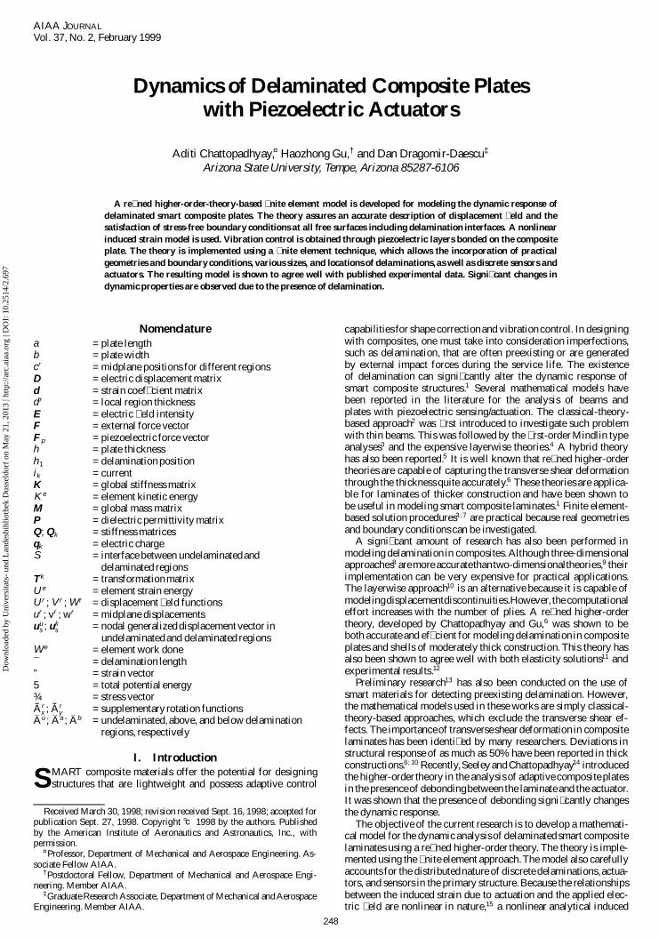
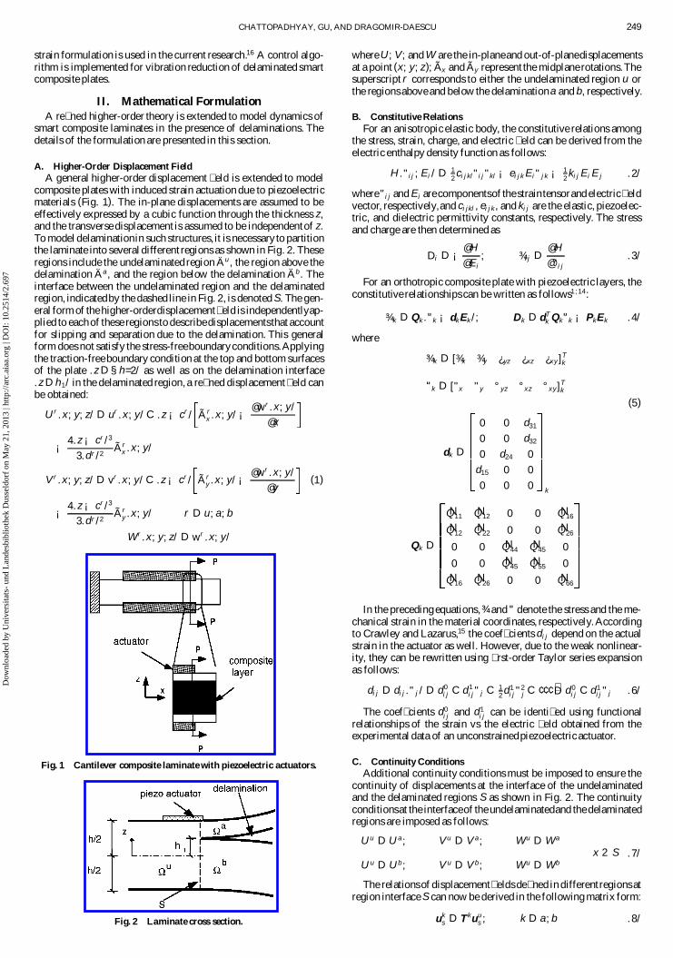
A. Higher-Order Displacement FieldA general higher-order displacement � eld is extended to model
composite plates with induced strain actuation due to piezoelectricmaterials (Fig. 1). The in-plane displacements are assumed to beeffectively expressed by a cubic function through the thickness z,and the transverse displacement is assumed to be independentof z.To model delaminationin such structures, it is necessary to partitionthe laminate into several different regions as shown in Fig. 2. Theseregions include the undelaminated region Äu , the region above thedelamination Äa , and the region below the delamination Äb . Theinterface between the undelaminated region and the delaminatedregion, indicatedby the dashed line in Fig. 2, is denoted S. The gen-eral form of the higher-orderdisplacement� eld is independentlyap-plied to each of these regions to describedisplacementsthat accountfor slipping and separation due to the delamination. This generalform does not satisfy the stress-freeboundaryconditions.Applyingthe traction-free boundary condition at the top and bottom surfacesof the plate .z D §h=2/ as well as on the delamination interface.z D h1/ in the delaminated region, a re� ned displacement � eld canbe obtained:
U r .x; y; z/ D ur .x; y/ C .z ¡ cr / Ã rx .x; y/ ¡
@wr .x; y/
@x
¡ 4.z ¡ cr /3
3.dr /2Ã r
x .x; y/
V r .x; y; z/ D vr .x; y/ C .z ¡ cr / Ã ry .x; y/ ¡ @wr .x; y/
@y(1)
¡ 4.z ¡ cr /3
3.dr /2Ã r
y .x; y/ r D u; a; b
W r .x; y; z/ D wr .x; y/
Fig. 1 Cantilever composite laminate with piezoelectric actuators.
Fig. 2 Laminate cross section.
where U; V; and W are the in-planeand out-of-planedisplacementsat a point (x; y; z); Ãx and Ãy represent the midplane rotations.Thesuperscript r corresponds to either the undelaminated region u orthe regions above and below the delaminationa and b, respectively.
B. Constitutive RelationsFor an anisotropic elastic body, the constitutive relations among
the stress, strain, charge, and electric � eld can be derived from theelectric enthalpy density function as follows:
H ."i j ; Ei / D 12ci j kl"i j "kl ¡ ei j k Ei " j k ¡ 1
2ki j Ei E j .2/
where"i j and Ei are componentsof the straintensorand electric� eldvector, respectively,and ci jkl , ei j k , and ki j are the elastic, piezoelec-tric, and dielectric permittivity constants, respectively. The stressand charge are then determined as
Di D ¡@ H
@ Ei; ¾i j D
@ H
@"i j.3/
For an orthotropic composite plate with piezoelectric layers, theconstitutive relationships can be written as follows1 ;14:
_
¾ k D Qk ._
"k ¡ dk Ek /; Dk D dTk Qk
_
"k ¡ PkEk .4/
where_
¾ k D [¾x ¾y ¿yz ¿xz ¿x y ]Tk
_
"k D ["x "y °yz °x z °x y]Tk
(5)
dk D
0 0 d31
0 0 d32
0 d24 0
d15 0 0
0 0 0 k
Qk D
NQ11NQ12 0 0 NQ16
NQ12NQ22 0 0 NQ26
0 0 NQ44NQ45 0
0 0 NQ45NQ55 0
NQ16NQ26 0 0 NQ66
In the preceding equations,_
¾ and_
" denote the stress and the me-chanical strain in the material coordinates, respectively.Accordingto Crawley and Lazarus,15 the coef� cients di j depend on the actualstrain in the actuator as well. However, due to the weak nonlinear-ity, they can be rewritten using � rst-order Taylor series expansionas follows:
di j D di j ." j / D d0i j C d1
i j " j C 12d1
i j "2j C ¢ ¢ ¢ »D d0
i j C d1i j " j .6/
The coef� cients d0i j and d1
i j can be identi� ed using functionalrelationships of the strain vs the electric � eld obtained from theexperimental data of an unconstrainedpiezoelectric actuator.
C. Continuity ConditionsAdditional continuity conditions must be imposed to ensure the
continuity of displacements at the interface of the undelaminatedand the delaminated regions S as shown in Fig. 2. The continuityconditionsat the interfaceof the undelaminatedand the delaminatedregions are imposed as follows:
U u D U a; V u D V a; W u D W a
x 2 SU u D U b; V u D V b; W u D W b
.7/
The relationsof displacement� elds de� ned in differentregions atregion interface S can now be derived in the following matrix form:
uks D Tkuu
s ; k D a; b .8/
Dow
nloa
ded
by U
nive
rsita
ts-
und
Lan
desb
iblio
thek
Dus
seld
orf
on M
ay 2
1, 2
013
| http
://ar
c.ai
aa.o
rg |
DO
I: 1
0.25
14/2
.697
250 CHATTOPADHYAY, GU, AND DRAGOMIR-DAESCU
D. Control EquationsBecause piezoelectric sensors can accurately detect strain rate
when they are connected with a current ampli� er and proportionalfeedback is the simplest to apply for structural vibration control,a piezoelectric sensor model is developed here for monitoring theproportionalvariablesthat are necessaryfor controlfeedback.Whenthe kth piezoelectric sensor layer is deformed, it accumulates anelectric charge on its surface electrode, which is given by
qk .t/ DA z
Dk dz dA DA z
Qd_
"k dz dA .9/
The current developed from the electric charge is obtained bydifferentiating the charge equation [Eq. (9)] with respect to time:
ik .t/ D Pqk.t/ DA z
Q[d._
"/_." C Pd.
_
"/_
"] dz dA .10/
In designing a control law using the Lyapunov direct method,the structural stability in the Lyapunov sense is guaranteed if thefeedback actuator voltage is selected as
Ek.t/ D Gik .t/ D GA z
Qk[d._
"/_." C Pd.
_
"/_
"] dz dA .11/
with gain G > 0. The collocated sensor-actuator was used in thisresearch. It is assumed that the energy stored in the electric � eld inthe sensor is small enoughcomparedwith the actuator,and its effectcan be neglected.
III. Finite Element ImplementationThe � nite elementmethodis used to implementthe re� nedhigher-
ordertheorybecauseit allowsfor theanalysisof practicalgeometriesand boundary conditions. The � nite element equations are derivedusing the discretized form of Hamilton’s principle, which is statedas follows:
±5 Dt2
t1
Ne
e D 1
[±K e ¡ ±U e C ±W e] dt D 0 .12/
where t1 and t2 are the initial and the � nal times, respectively, and±K e; ±U e, and ±W e represent the elemental variations in the kineticenergy,the strain energy,and theworkdone,respectively.The global� nite element equations of motion are then expressed as follows:
Mu C Ku D F C FP .13/
A 16-termpolynomialshape functionis used for interpolatingtheout-of-planedisplacementsw, whereas bilinear shape functions areused for the other unknown functions (u; v; Ãx ; and Ãy ).
IV. Results and DiscussionsNumerical results are presented � rst to compare the higher-order
theory with published experimental results to validate its accuracy.Next, dynamicresponseandvibrationcontrolusingpiezoelectricac-tuation are presented for a cantilever composite plate with varyingdelamination lengths. The results are presented for [0 deg/90 deg/0 deg/90 deg]s graphite/epoxy laminateswith surface bondedpiezo-electric actuator pairs. The material properties used for the smartcomposite plate are listed in Table 1, where E is Young’s modulusand º is Poisson’s ratio. Plates with length a D 0:127 m, thicknessh D 0:001016m, and width b D 0:0127m areconsidered.The piezo-
Table 1 Material properties
Property Graphite/epoxy PZT
E1, GPA 134.4 63E2, GPA 10.3 63º12 0.33 0.33G12; G13 , GPA 5 24.2G23, GPA 2 24.2½; £103 kg/m3 1.477 7.6d0; £10¡12 m/V —— 24.7d1; £10¡7 m/V —— 8.38
Table 2 First natural frequencyfor delamination along the midplane
Delamination Experiment Current higher-length, mm (average), Hz order theory, Hz
0 79.833 82.11925.4 78.168 80.05650.8 75.375 75.62076.2 66.958 67.14291.6 57.542 57.813
electric actuator-sensor pairs have dimensions of L p D 0:0127 m,h p D 0:000254 m, and bp D 0:0127 m, located at differentpositions(see Fig. 1).
The results from the current approach are compared with exper-imental data obtained by Shen and Grady17 as show in Table 2.Delamination lies on the midplane of the plate and starts from theclamped end. The natural frequencies obtained from the higher-order-theory-based� nite element approach show good correlationwith experimental data, especially in the delaminated case. Thisindicates that the higher-order-theory-based model provides an ef-fective tool for modeling delamination.
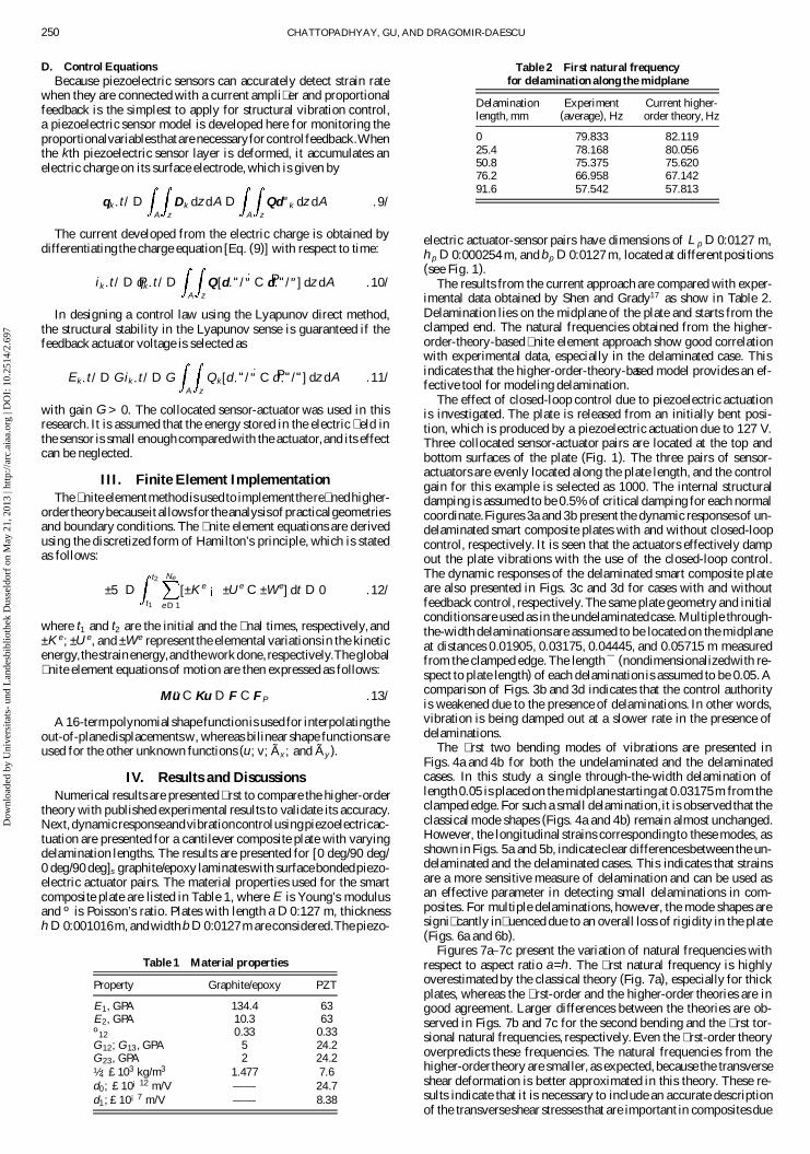
The effect of closed-loop control due to piezoelectric actuationis investigated. The plate is released from an initially bent posi-tion, which is produced by a piezoelectric actuation due to 127 V.Three collocated sensor-actuator pairs are located at the top andbottom surfaces of the plate (Fig. 1). The three pairs of sensor-actuators are evenly located along the plate length, and the controlgain for this example is selected as 1000. The internal structuraldamping is assumed to be 0.5% of critical damping for each normalcoordinate.Figures 3a and 3b present the dynamic responsesof un-delaminated smart composite plates with and without closed-loopcontrol, respectively. It is seen that the actuators effectively dampout the plate vibrations with the use of the closed-loop control.The dynamic responses of the delaminated smart composite plateare also presented in Figs. 3c and 3d for cases with and withoutfeedback control, respectively.The same plate geometry and initialconditions are used as in the undelaminatedcase. Multiple through-the-width delaminationsare assumed to be located on the midplaneat distances 0.01905, 0.03175, 0.04445, and 0.05715 m measuredfrom the clamped edge. The length ¯ (nondimensionalizedwith re-spect to plate length) of each delamination is assumed to be 0.05. Acomparison of Figs. 3b and 3d indicates that the control authorityis weakened due to the presence of delaminations. In other words,vibration is being damped out at a slower rate in the presence ofdelaminations.
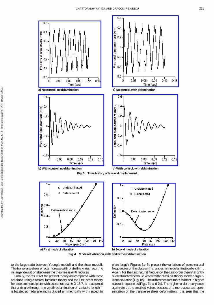
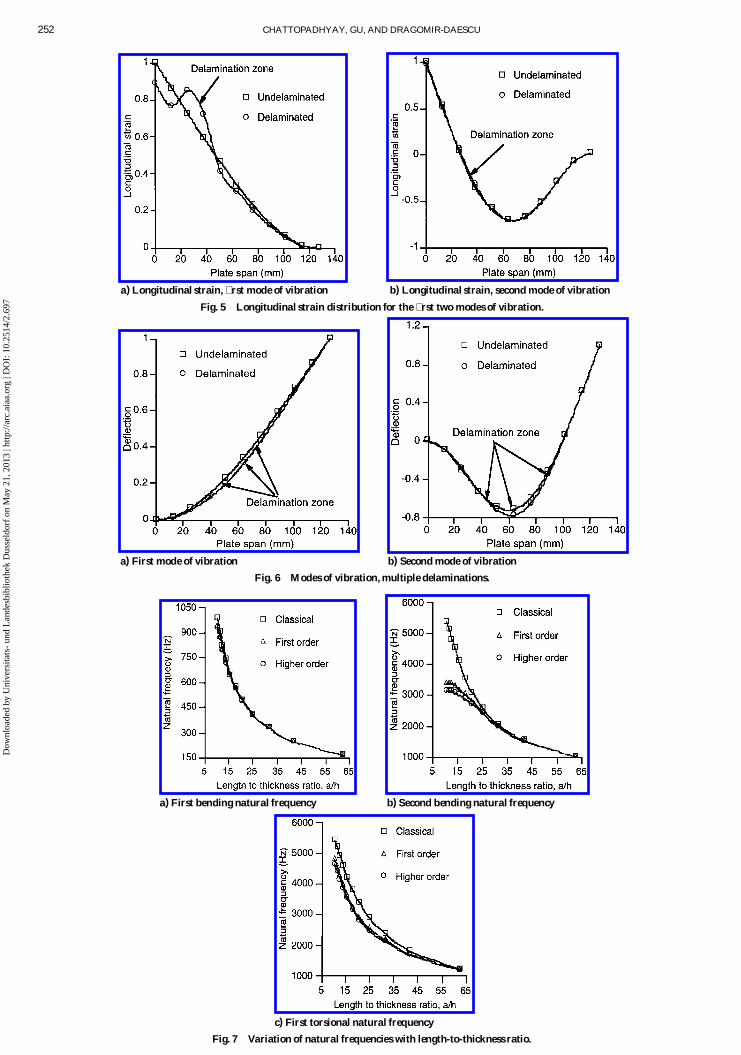
The � rst two bending modes of vibrations are presented inFigs. 4a and 4b for both the undelaminated and the delaminatedcases. In this study a single through-the-width delamination oflength 0.05 is placed on the midplane startingat 0.03175m from theclamped edge. For such a small delamination, it is observed that theclassical mode shapes (Figs. 4a and 4b) remain almost unchanged.However, the longitudinal strains correspondingto these modes, asshown in Figs. 5a and 5b, indicateclear differencesbetween the un-delaminated and the delaminated cases. This indicates that strainsare a more sensitive measure of delamination and can be used asan effective parameter in detecting small delaminations in com-posites. For multiple delaminations, however, the mode shapes aresigni� cantly in� uenced due to an overall loss of rigidity in the plate(Figs. 6a and 6b).
Figures 7a–7c present the variation of natural frequencies withrespect to aspect ratio a=h. The � rst natural frequency is highlyoverestimated by the classical theory (Fig. 7a), especially for thickplates, whereas the � rst-order and the higher-order theories are ingood agreement. Larger differences between the theories are ob-served in Figs. 7b and 7c for the second bending and the � rst tor-sional natural frequencies, respectively.Even the � rst-order theoryoverpredicts these frequencies. The natural frequencies from thehigher-ordertheory are smaller, as expected, because the transverseshear deformation is better approximated in this theory. These re-sults indicate that it is necessary to include an accurate descriptionof the transverseshear stresses that are important in composites due
Dow
nloa
ded
by U
nive
rsita
ts-
und
Lan
desb
iblio
thek
Dus
seld
orf
on M
ay 2
1, 2
013
| http
://ar
c.ai
aa.o
rg |
DO
I: 1
0.25
14/2
.697
CHATTOPADHYAY, GU, AND DRAGOMIR-DAESCU 251
a) No control, no delamination
b) With control, no delamination
c) No control, with delamination
d) With control, with delamination
Fig. 3 Time history of free end displacement.
a) First mode of vibration b) Second mode of vibration
Fig. 4 Modes of vibration, with and without delamination.
to the large ratio between Young’s moduli and the shear moduli.The transverse shear effects increase with plate thickness, resultingin larger deviationsbetween the theories as a=h reduces.
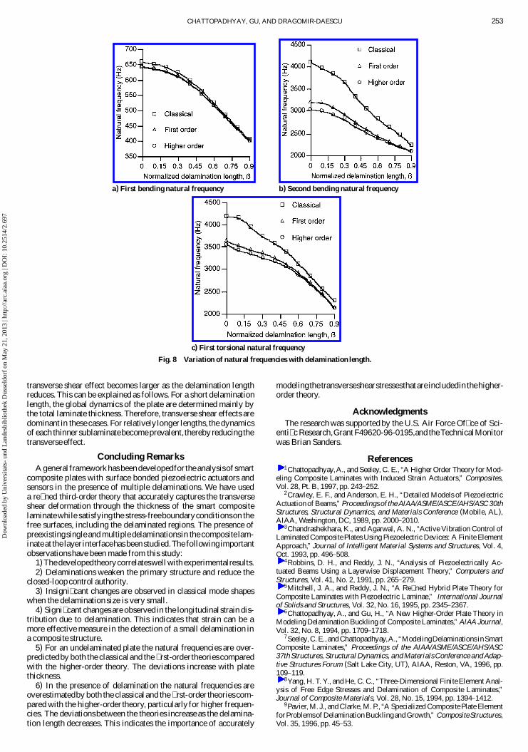
Finally, the results of the present theory are compared with thoseobtained using classical laminate theory and the � rst-order theoryfor a delaminated plate with aspect ratio a=h D 15:7. It is assumedthat a single through-the-width delamination of variable length ¯is located at midplane and is placed symmetrically with respect to
plate length. Figures 8a–8c present the variations of some naturalfrequenciesof the plate with changes in the delamination length ¯ .Again, for the � rst natural frequency, the � rst-order theory slightlyoverestimatesthe value,whereas the classical theoryshows a signif-icant deviation(Fig. 8a). The differencesare more evident in highernatural frequencies (Figs. 7b and 7c). The higher-order theory onceagain yields the smallest values because of a more accurate repre-sentation of the transverse shear deformation. It is seen that the
Dow
nloa
ded
by U
nive
rsita
ts-
und
Lan
desb
iblio
thek
Dus
seld
orf
on M
ay 2
1, 2
013
| http
://ar
c.ai
aa.o
rg |
DO
I: 1
0.25
14/2
.697
252 CHATTOPADHYAY, GU, AND DRAGOMIR-DAESCU
a) Longitudinal strain, � rst mode of vibration b) Longitudinal strain, second mode of vibration
Fig. 5 Longitudinal strain distribution for the � rst two modes of vibration.
a) First mode of vibration b) Second mode of vibration
Fig. 6 Modes of vibration, multiple delaminations.
a) First bending natural frequency b) Second bending natural frequency
c) First torsional natural frequency
Fig. 7 Variation of natural frequencies with length-to-thickness ratio.
Dow
nloa
ded
by U
nive
rsita
ts-
und
Lan
desb
iblio
thek
Dus
seld
orf
on M
ay 2
1, 2
013
| http
://ar
c.ai
aa.o
rg |
DO
I: 1
0.25
14/2
.697
CHATTOPADHYAY, GU, AND DRAGOMIR-DAESCU 253
a) First bending natural frequency b) Second bending natural frequency
c) First torsional natural frequency
Fig. 8 Variation of natural frequencies with delamination length.
transverse shear effect becomes larger as the delamination lengthreduces. This can be explained as follows. For a short delaminationlength, the global dynamics of the plate are determined mainly bythe total laminate thickness. Therefore, transverse shear effects aredominant in these cases. For relatively longer lengths, the dynamicsof each thinner sublaminatebecome prevalent,thereby reducing thetransverse effect.
Concluding RemarksA general frameworkhas beendevelopedfor the analysisof smart
composite plates with surface bonded piezoelectric actuators andsensors in the presence of multiple delaminations. We have useda re� ned third-order theory that accurately captures the transverseshear deformation through the thickness of the smart compositelaminate while satisfying the stress-freeboundaryconditionson thefree surfaces, including the delaminated regions. The presence ofpreexistingsingle and multiple delaminationsin the composite lam-inate at the layer interfacehas been studied.The followingimportantobservationshave been made from this study:
1)The developedtheorycorrelateswell with experimentalresults.2) Delaminations weaken the primary structure and reduce the
closed-loop control authority.3) Insigni� cant changes are observed in classical mode shapes
when the delamination size is very small.4) Signi� cant changes are observed in the longitudinalstrain dis-
tribution due to delamination. This indicates that strain can be amore effective measure in the detection of a small delamination ina composite structure.
5) For an undelaminated plate the natural frequencies are over-predictedby both the classical and the � rst-ordertheories comparedwith the higher-order theory. The deviations increase with platethickness.
6) In the presence of delamination the natural frequencies areoverestimatedby both the classical and the � rst-order theories com-pared with the higher-order theory, particularly for higher frequen-cies. The deviationsbetween the theories increase as the delamina-tion length decreases. This indicates the importance of accurately
modelingthe transverseshearstressesthat are includedin thehigher-order theory.
AcknowledgmentsThe research was supported by the U.S. Air Force Of� ce of Sci-
enti� c Research,Grant F49620-96-0195,and the TechnicalMonitorwas Brian Sanders.
References1Chattopadhyay,A., and Seeley, C. E., “A Higher Order Theory for Mod-
eling Composite Laminates with Induced Strain Actuators,” Composites,Vol. 28, Pt. B, 1997, pp. 243–252.
2Crawley, E. F., and Anderson, E. H., “Detailed Models of PiezoelectricActuation of Beams,” Proceedings of the AIAA/ASME/ASCE/AHS/ASC 30thStructures, Structural Dynamics, and Materials Conference (Mobile, AL),AIAA, Washington, DC, 1989, pp. 2000–2010.
3Chandrashekhara, K., and Agarwal, A. N., “Active Vibration Control ofLaminated Composite Plates Using Piezoelectric Devices: A Finite ElementApproach,” Journal of Intelligent Material Systems and Structures, Vol. 4,Oct. 1993, pp. 496–508.
4Robbins, D. H., and Reddy, J. N., “Analysis of Piezoelectrically Ac-tuated Beams Using a Layerwise Displacement Theory,” Computers andStructures, Vol. 41, No. 2, 1991, pp. 265–279.
5Mitchell, J. A., and Reddy, J. N., “A Re� ned Hybrid Plate Theory forComposite Laminates with Piezoelectric Laminae,” International Journalof Solids and Structures, Vol. 32, No. 16, 1995, pp. 2345–2367.
6Chattopadhyay, A., and Gu, H., “A New Higher-Order Plate Theory inModeling Delamination Buckling of Composite Laminates,” AIAA Journal,Vol. 32, No. 8, 1994, pp. 1709–1718.
7Seeley, C. E., and Chattopadhyay,A., “ModelingDelaminations inSmartComposite Laminates,” Proceedings of the AIAA/ASME/ASCE/AHS/ASC37th Structures, Structural Dynamics, and Materials Conference and Adap-tive Structures Forum (Salt Lake City, UT), AIAA, Reston, VA, 1996, pp.109–119.
8Yang, H. T. Y., and He, C. C., “Three-Dimensional Finite Element Anal-ysis of Free Edge Stresses and Delamination of Composite Laminates,”Journal of Composite Materials, Vol. 28, No. 15, 1994, pp. 1394–1412.
9Pavier, M. J., and Clarke, M. P., “A Specialized Composite Plate ElementforProblemsof Delamination Bucklingand Growth,” CompositeStructures,Vol. 35, 1996, pp. 45–53.
Dow
nloa
ded
by U
nive
rsita
ts-
und
Lan
desb
iblio
thek
Dus
seld
orf
on M
ay 2
1, 2
013
| http
://ar
c.ai
aa.o
rg |
DO
I: 1
0.25
14/2
.697

254 CHATTOPADHYAY, GU, AND DRAGOMIR-DAESCU
10Barbero, E. J., and Reddy, J. N., “Modeling of Delamination in Com-posite Laminates Using a Layer-Wise Plate Theory,” International Journalof Solids and Structures, Vol. 28, No. 3, 1991, pp. 373–388.
11Chattopadhyay, A., and Gu, H., “Elasticity Approach for DelaminationBuckling of Composite Beam Plates,” AIAA Journal, Vol. 36, No. 8, 1998,pp. 1529–1534.
12Chattopadhyay, A., and Gu, H., “An Experimental Investigation of De-lamination Buckling and Postbuckling of Composite Laminates,” Compos-ites Science and Technology (to be published).
13Keilers, C. H., and Chang, F. K., “IdentifyingDelamination in Compos-ite Beams Using Built-In Piezoelectric: Part I—Experiments and Analysis,Part II—An identi� cation Method,” Journal of Intelligent Material Systemand Structures, Vol. 5, No. 5, 1995, pp. 649–663.
14Seeley, C. E., and Chattopadhyay,A., “Modeling of Adaptive Compos-ites Including Debonding,” International Journal of Solids and Structures
(to be published).15Crawley, E. F., and Lazarus, K. B., “Induced Strain Actuation of
Isotropic and Anisotropic Plates,” Proceedings of the AIAA/ASME/ASCE/AHS/ASC 30th Structures, Structural Dynamics, and Materials Conference(Mobile, AL), AIAA, Washington, DC, 1989, pp. 2000–2010.
16Chattopadhyay, A., Dragomir-Daescu, D., and Gu, H., “Dynamic Re-sponseofSmartCompositeswith Delamination,”Proceedingsof the Interna-tional Workshop on Structural Health Monitoring, Stanford Univ., Stanford,CA, 1997, pp. 729–740.
17Shen, M. H., and Grady, J. E., “Free Vibration of Delaminated Beams,”NASA TM-105582, 1992.
G. M. FaethEditor-in-Chief
Dow
nloa
ded
by U
nive
rsita
ts-
und
Lan
desb
iblio
thek
Dus
seld
orf
on M
ay 2
1, 2
013
| http
://ar
c.ai
aa.o
rg |
DO
I: 1
0.25
14/2
.697
This article has been cited by:
1. Pizhong Qiao, Fangliang Chen. 2012. On the improved dynamic analysis of delaminated beams. Journal of Soundand Vibration 331:5, 1143-1163. [CrossRef]
2. Quan Wang, Nan Wu. 2012. A review on structural enhancement and repair using piezoelectric materials and shapememory alloys. Smart Materials and Structures 21:1, 013001. [CrossRef]
3. N Wu, Q Wang. 2010. Repair of vibrating delaminated beam structures using piezoelectric patches. Smart Materialsand Structures 19:3, 035027. [CrossRef]
4. Raghavendran Mani, Dimitris C Lagoudas, Othon K Rediniotis. 2008. Active skin for turbulent drag reduction.Smart Materials and Structures 17:3, 035004. [CrossRef]
5. Nikolaos Chrysochoidis, Dimitris SaravanosHigh Frequency Response of Delaminated Composite Beams withActive Piezoelectric Sensors . [Citation] [PDF] [PDF Plus]
6. Nikolaos A. Chrysochoidis, Dimitris A. Saravanos. 2007. Generalized layerwise mechanics for the static and modalresponse of delaminated composite beams with active piezoelectric sensors. International Journal of Solids andStructures 44:25-26, 8751-8768. [CrossRef]
7. Christian N. Della, Dongwei Shu. 2007. Vibration of Delaminated Composite Laminates: A Review. AppliedMechanics Reviews 60:1, 1. [CrossRef]
8. Anindya Ghoshal, Heung Soo Kim, Jaehwan Kim, Seung-Bok Choi, William H. Prosser, Hsiang Tai. 2006.Modeling delamination in composite structures by incorporating the Fermi–Dirac distribution function and hybriddamage indicators. Finite Elements in Analysis and Design 42:8-9, 715-725. [CrossRef]
9. Heung Soo Kim, Anindya Ghoshal, Jaehwan Kim, Seung-Bok Choi. 2006. Transient analysis of delaminated smartcomposite structures by incorporating the Fermi–Dirac distribution function. Smart Materials and Structures 15:2,221-231. [CrossRef]
10. S. Kapuria, G.G.S. Achary. 2005. A coupled consistent third-order theory for hybrid piezoelectric plates. CompositeStructures 70:1, 120-133. [CrossRef]
11. Anindya Ghoshal, Heung Soo Kim, Aditi Chattopadhyay, William H. Prosser. 2005. Effect of delamination ontransient history of smart composite plates. Finite Elements in Analysis and Design 41:9-10, 850-874. [CrossRef]
12. Dongchang Sun, Liyong Tong. 2004. An equivalent model for smart beams with debonded piezoelectric patches.Journal of Sound and Vibration 276:3-5, 933-956. [CrossRef]
13. Nikolaos A Chrysochoidis, Dimitris A Saravanos. 2004. Assessing the effects of delamination on the dampeddynamic response of composite beams with piezoelectric actuators and sensors. Smart Materials and Structures 13:4,733-742. [CrossRef]
14. Dimitris Varelis, Dimitris Saravanos. 2004. Mechanics and Finite Element for the Nonlinear Response of ActiveLaminated Piezoelectric Composite Plates. AIAA Journal 42:6, 1227-1235. [Citation] [PDF] [PDF Plus]
15. S. Kapuria. 2004. A Coupled Zig-Zag Third-Order Theory for Piezoelectric Hybrid Cross-Ply Plates. Journal ofApplied Mechanics 71:5, 604. [CrossRef]
16. Junqian Zhang, Benniu Zhang, Jinghong Fan. 2003. A coupled electromechanical analysis of a piezoelectric layerbonded to an elastic substrate: Part I, development of governing equations. International Journal of Solids andStructures 40:24, 6781-6797. [CrossRef]
17. Y Y Li, L Cheng, L H Yam, Y J Yan. 2003. Numerical modeling of a damaged plate with piezoelectric actuation.Smart Materials and Structures 12:4, 524-532. [CrossRef]
18. Anindya Ghoshal, Aditi Chattopadhyay, Heung Soo KimDelamination Effect on Transient History of SmartComposite Plates . [Citation] [PDF] [PDF Plus]
19. Othon Rediniotis, Dimitris Lagoudas, Raghavendran Mani, Lance Traub, George Karniadakis, RichardAllenCOMPUTATIONAL AND EXPERIMENTAL STUDIES OF AN ACTIVE SKIN FOR TURBULENTDRAG REDUCTION . [Citation] [PDF] [PDF Plus]
20. Devendra P Garg, Mohammed A Zikry, Gary L Anderson. 2001. Current and potential future research activitiesin adaptive structures: an ARO perspective. Smart Materials and Structures 10:4, 610-623. [CrossRef]
Dow
nloa
ded
by U
nive
rsita
ts-
und
Lan
desb
iblio
thek
Dus
seld
orf
on M
ay 2
1, 2
013
| http
://ar
c.ai
aa.o
rg |
DO
I: 1
0.25
14/2
.697


![Systems with piezoelectric actuators · 98 4. Systems with piezoelectric actuators Figure 4.3: Frequency response between A and B, with and without control [Is2 +Ω2 −g s+g ΦT(bkbT)Φ]z](https://img.pdfslide.us/doc/110x75/5e9d43522d66d6493c6f5244/systems-with-piezoelectric-actuators-98-4-systems-with-piezoelectric-actuators.jpg)