Embed Size (px)
Citation preview

Bi-stable composites with piezoelectric
actuators for shape change
C.R.Bowen1, A.I.T.Salo2 , R.Butler1 , E. Chang1 and H.A.Kim1 1Department of Mechanical Engineering, University of Bath, Bath, BA2 7AY, UK
2 Sport and Exercise Science, School for Health, University of Bath, Bath, BA2 7AY, UK
Keywords: composite, piezoelectric, morphing, smart, bi-stable
Abstract. Unsymmetrical carbon fibre/epoxy composites with bonded piezoelectric fibre actuators
were investigated as a means to shape change, or morph, composite structures. A carbon fibre
cantilever was examined along with its response to applied strains (from piezoelectric actuators), with
emphasis on the characterisation of shape/deflection and the reproducibility of the shape/deflection of
the structure.
Introduction
There is considerable interest in structures that are able to change shape, or morph, to meet changing
performance requirements [1]; for example to achieve high levels of manoeuvrability in micro air
vehicles [2] or to enhance helicopter rotor blade efficiency [3]. A variety of mechanisms have been
investigated to achieve shapes change in structures. These range from the use of compliant
mechanisms [4] to bi-stable concepts that exhibit snap-through behaviour from one stable state to
another, occurring for example, within trusses [5] or un-symmetric composite laminates [6,7].
Materials used to induce snap-through include shape memory alloys [8,9], which can induce high
strains (8%) at low frequency [10] and piezoelectric materials that are able to generate high forces at
high frequency, although the developed strains tend to be small; typically only 0.1-0.4%. However,
the use of piezoelectric single crystals can produce up to 1% [11].
Due to the low maximum strain of piezoelectric materials, the introduction of bending, buckling or
bi-stability into a structure is often used as an amplification mechanism to generate useful deflections.
Shultz and Hyer [5,6] examined an unsymmetrical cross ply [0/90]T laminate with a macro fibre
piezoelectric composite bonded to its surface to achieve snap-through from one stable state to
another. A potential advantage of this mechanism is that large changes in shape can be achieved, with
limited power requirements, as continuous power is not needed. The aim of this paper is to
demonstrate the reproducibility of the response of a cantilever structure manufactured from an
un-symmetric composite with bonded piezoelectric actuators to induce snap-through.
Experimental
Un-symmetric carbon fibre composites were manufactured using Hexcel M21/T800 carbon fibre
epoxy pre-pregs. Two composites were manufactured; a ‘thin’ 2-ply sample with a [0,90] lay-up and a
‘thick’ 4-ply sample with a [0,0,90,90] lay-up. After laying-up the composite pre-pregs and curing at
180ºC at 100psi the samples were cut to 70mm x 425mm dimension. The thickness of the ‘thin’ and
‘thick’ composites was 0.45mm and 0.95mm respectively. Fig.1 shows both composites and their
two stable states, designated as ‘State I’ and ‘State II’ which result from high temperature curing of
their un-symmetric lay-up. Due to the lower stiffness and greater curvature of the thin composite,
28mm x 14mm piezoelectric macro-fibre composite (MFC) actuators from Smart Materials Corp.,
USA (Actuator no. M2814 d33) were bonded to the composite whilst in State II. Two actuators were
Key Engineering Materials Vols. 334-335 (2007) pp. 1109-1112online at http://www.scientific.net© (2007) Trans Tech Publications, Switzerland
All rights reserved. No part of contents of this paper may be reproduced or transmitted in any form or by any means without thewritten permission of the publisher: Trans Tech Publications Ltd, Switzerland, www.ttp.net. (ID: 138.38.32.84-12/01/07,13:44:02)

used in an attempt to actuate them independently and provide a range of possible shapes, although
only data from applying electric potentials to Actuator 1 is presented here. Fig. 1a identifies the
location of the actuators.
Two separate analysing sessions were conducted using motion analysis techniques. The first was
to analyse the shape of the composites, before attaching the actuators, and to repeat the snap-through
to assess the reproducibility of the stable states/shapes. A digital video camera recorder (Sony
DCR-TRV 900E, Sony Corporation, Japan) operating at 50 fields per second was set up above the
composites which were bent into State I and placed on their side to minimise distortion due to self
weight.
(a) (b)
Figure 1. Images of composites and their states. (a) State I and (b) State II. The actuators were
attached to the thinner composite.
The camera lens was at the height of 2.70 m from the floor, and a plumb line was used to align the
lens axis perpendicularly down and pointing to the middle of the analysing area. The plane, where the
closest edge of the composite to the camera would be located, was calibrated with a rectangular
calibration object of 349 mm x 262 mm for scaling purposes. Both thick and thin composites were
bent into State I and the shape/profile was videotaped. The composites were straightened into State II
and then bent again into State I, by hand, between the six individual recordings. The video clips were
subsequently transferred to a computer. The edge of the bent composite, and the four corners of the
calibration object, were manually digitised on Peak Motus® (Peak Performance, Colorado, USA);
achieved by using a mouse to select 33 points at the edge of the composite. Firstly, the origin and the
end of the composites were digitised, after which the
further 31 points were selected in the approximate middle
of the existing two points. This provided an approximately
equal distribution of the points throughout the whole length
of the composite. The digitised area consisted of 1440 x
1152 pixels, resulting in an effective resolution of
digitisation of 300µm in both horizontal and vertical
directions. After the scaling and reconstruction, the raw
co-ordinates of 33 points were exported to Excel®
software.
The second analysis was used to assess the shape change
of the thin composite under piezoelectric actuation. For
this experiment, electrical potentials were applied to
Actuator 1 while the composite was held between two steel
plates in a cantilever configuration, as shown in Fig. 2. In
this case the video camera lens was located horizontally
2.70 m away from the cantilever. Again, the lens axis was
perpendicular to the plane where the cantilever was located.
This plane was calibrated at the same fashion as above.
Figure 2 Thin composite used as a
cantilever with stable states labelled
(a) and (b). No electric potential was
applied in these images.
Actuator 1
Actuator 2
(a
)
(b)
30mm
STATE I STATE II
40mm Actuator 2 Actuator 1
Advances in Composite Materials and Structures1110
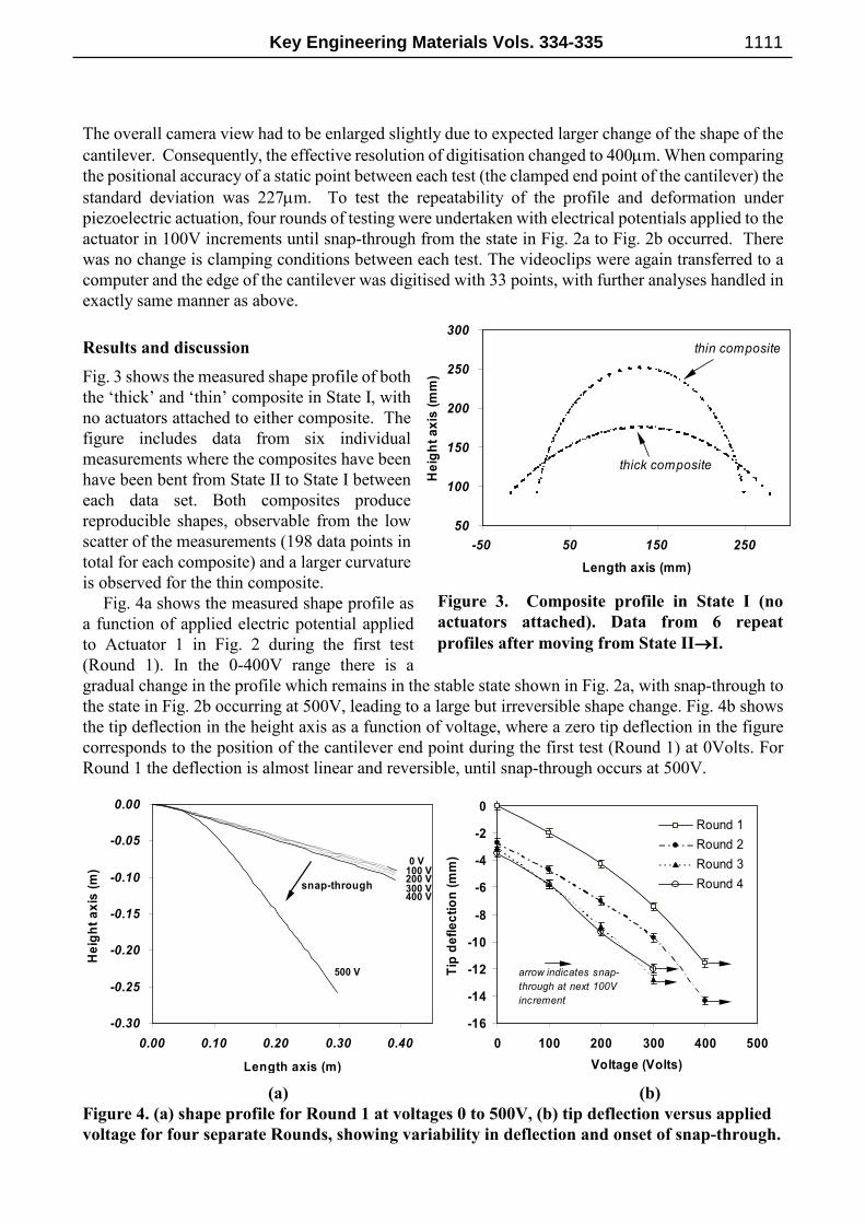
The overall camera view had to be enlarged slightly due to expected larger change of the shape of the
cantilever. Consequently, the effective resolution of digitisation changed to 400µm. When comparing
the positional accuracy of a static point between each test (the clamped end point of the cantilever) the
standard deviation was 227µm. To test the repeatability of the profile and deformation under
piezoelectric actuation, four rounds of testing were undertaken with electrical potentials applied to the
actuator in 100V increments until snap-through from the state in Fig. 2a to Fig. 2b occurred. There
was no change is clamping conditions between each test. The videoclips were again transferred to a
computer and the edge of the cantilever was digitised with 33 points, with further analyses handled in
exactly same manner as above.
Results and discussion
Fig. 3 shows the measured shape profile of both
the ‘thick’ and ‘thin’ composite in State I, with
no actuators attached to either composite. The
figure includes data from six individual
measurements where the composites have been
have been bent from State II to State I between
each data set. Both composites produce
reproducible shapes, observable from the low
scatter of the measurements (198 data points in
total for each composite) and a larger curvature
is observed for the thin composite.
Fig. 4a shows the measured shape profile as
a function of applied electric potential applied
to Actuator 1 in Fig. 2 during the first test
(Round 1). In the 0-400V range there is a
gradual change in the profile which remains in the stable state shown in Fig. 2a, with snap-through to
the state in Fig. 2b occurring at 500V, leading to a large but irreversible shape change. Fig. 4b shows
the tip deflection in the height axis as a function of voltage, where a zero tip deflection in the figure
corresponds to the position of the cantilever end point during the first test (Round 1) at 0Volts. For
Round 1 the deflection is almost linear and reversible, until snap-through occurs at 500V.
-0.30
-0.25
-0.20
-0.15
-0.10
-0.05
0.00
0.00 0.10 0.20 0.30 0.40
Length axis (m)
Height axis (m)
0 V100 V200 V300 V400 V
500 V
snap-through
-16
-14
-12
-10
-8
-6
-4
-2
0
0 100 200 300 400 500
Voltage (Volts)
Tip deflection (mm)
Round 1
Round 2
Round 3
Round 4
arrow indicates snap-
through at next 100V
increment
(a) (b)
Figure 4. (a) shape profile for Round 1 at voltages 0 to 500V, (b) tip deflection versus applied
voltage for four separate Rounds, showing variability in deflection and onset of snap-through.
50
100
150
200
250
300
-50 50 150 250
Length axis (mm)
Height axis (mm)
thin composite
thick composite
Figure 3. Composite profile in State I (no
actuators attached). Data from 6 repeat
profiles after moving from State II→→→→I.
Key Engineering Materials Vols. 334-335 1111

When repeating the testing a similar gradient of the tip deflection-voltage response before
snap-through was observed (see Fig.4b) with a mean gradient of 0.030mm/V and a standard deviation
of 0.002mm/V. This is in contrast to the piezoelectric actuator displacement which is ~1200 times
smaller at ~25nm/V (free displacement). Although the gradient in Fig. 4b is similar, the initial
position of the cantilever tip at 0V moves to a lower height between each test. In addition, in the first
two rounds the potentials of 0, 100, 200, 300 and 400 V applied to Actuator 1 kept the cantilever in the
shape in Fig. 2a, and the potential of 500 V caused snap-through of the cantilever from to that in Fig.
2b. In the latter two rounds, the potential of 400 V caused snap-through of the cantilever. These
changes in response could be due to non-linearity and hysteresis in the piezoelectric actuator or due to
a change in the clamping conditions of the cantilever, although examination of the position of the
clamping point revealed no significant movement between each test (less than the video resolution).
Conclusions
Unsymmetrical carbon fibre/epoxy composites with bonded piezoelectric actuators have been
investigated as a means to shape change, or morph, composite structures. A carbon fibre cantilever
was examined along with their response to applied strains (from piezoelectric actuators); with
emphasis on the characterisation of shape/deflection and the reproducibility of the shape/deflection of
the structure. The shapes formed by the unsymmetrical composites are reproducible and large changes
in shape and deflections can be obtained by the use of piezoelectric actuators. Reversible shape
changes in a single state are significantly less than irreversible changes that involve snap-through
from one state to the other. Although the stables shapes are reproducible, changes to the clamping
boundary conditions or the hysteretic nature of the actuator can lead to variability in the shape and
deflections observed. Future research is to investigate multiple actuators along the length of the
structure to introduce additional shape/profile change.
References
[1] M.G.Bawden: Aerospace America 41 (2003), p. 73.
[2] M. Abdulrahim, H. Garcia and R. Lind: Journal of Aircraft 42 (2005), p. 131.
[3] S. Shin, C.E.S. Cesnik, and S.R. Hall: J. Am. Helicopter Society 50 (2005), p. 178.
[4] D.S. Ramrkahyani, G.A.Lesieutre, M.Frecker, and S. Bharti: J. of Aircraft 42 (2005), p. 1615.
[5] K.A.Seffen, “Bi-stable concepts for reconfigurable structures”, Collection of Technical Papers -
AIAA/ASME/ASCE/AHS/ASC Structures, Structural Dynamics and Materials Conference,
Volume 1, 2004, p. 236-249.
[6] Schultz, M.R. and Hyer, M.W. 2004. “A morphing concept based on unsymmetric composite
laminates and piezoelectric MFC actuators”, Collection of Technical Papers -
AIAA/ASME/ASCE/AHS/ASC Structures, Structural Dynamics and Materials Conference,
Volume 4, 2004, Pages 3192-3204
[7] M.R. Schultz and M.W. Hyer: J. Intelligent Material Systems and Structures, 14 (2003), p. 795.
[8] W. Hufenbach, W. Gude and L. Kroll: Composites Science and Technology 62 (2002), p. 2201.
[9] M.L. Dano, M.W. Hyer: International Journal of Solids and Structures 40 (2003), p. 5949.
[10] J.N. Kudva: Journal of Intelligent Material Systems and Structures 15 (2004), p. 261.
[11] W. Keats Wilkie, D. J. Inman, J.M. Lloyd and J.W. High��J. of Intelligent Material Systems and
Structures 17 (2006), p.15.
Advances in Composite Materials and Structures1112


![Systems with piezoelectric actuators · 98 4. Systems with piezoelectric actuators Figure 4.3: Frequency response between A and B, with and without control [Is2 +Ω2 −g s+g ΦT(bkbT)Φ]z](https://img.pdfslide.us/doc/110x75/5e9d43522d66d6493c6f5244/systems-with-piezoelectric-actuators-98-4-systems-with-piezoelectric-actuators.jpg)