Embed Size (px)
Citation preview
Hindawi Publishing CorporationEURASIP Journal on Wireless Communications and NetworkingVolume 2010, Article ID 143413, 12 pagesdoi:10.1155/2010/143413
Research Article
Dynamic Resource Partitioning for DownlinkFemto-to-Macro-Cell Interference Avoidance
Zubin Bharucha,1 Andreas Saul,1 Gunther Auer,1 and Harald Haas2
1DOCOMO Communications Laboratories Europe GmbH, Landsberger Straße 312, 80687 Munich, Germany2 School of Engineering and Electronics, Institute for Digital Communications, Joint Research Institute for Signal and Image Processing,The University of Edinburgh, Edinburgh EH9 3JL, UK
Correspondence should be addressed to Zubin Bharucha, [email protected]
Received 31 December 2009; Accepted 26 April 2010
Academic Editor: Holger Claussen
Copyright © 2010 Zubin Bharucha et al. This is an open access article distributed under the Creative Commons AttributionLicense, which permits unrestricted use, distribution, and reproduction in any medium, provided the original work is properlycited.
Femto-cells consist of user-deployed Home Evolved NodeBs (HeNBs) that promise substantial gains in system spectral efficiency,coverage, and data rates due to an enhanced reuse of radio resources. However, reusing radio resources in an uncoordinated,random fashion introduces potentially destructive interference to the system, both, in the femto and macro layers. An especiallycritical scenario is a closed-access femto-cell, cochannel deployed with a macro-cell, which imposes strong downlink interferenceto nearby macro user equipments (UEs) that are not permitted to hand over to the femto-cell. In order to maintain reliableservice of macro-cells, it is imperative to mitigate the destructive femto-cell to macro-cell interference. The contribution in thispaper focuses on mitigating downlink femto-cell to macro-cell interference through dynamic resource partitioning, in the way thatHeNBs are denied access to downlink resources that are assigned to macro UEs in their vicinity. By doing so, interference to themost vulnerable macro UEs is effectively controlled at the expense of a modest degradation in femto-cell capacity. The necessarysignaling is conveyed through downlink high interference indicator (DL-HII) messages over the wired backbone. Extensive systemlevel simulations demonstrate that by using resource partitioning, for a sacrifice of 4% of overall femto downlink capacity, macroUEs exposed to high HeNB interference experience a tenfold boost in capacity.
1. Introduction
There is a growing demand for increased user and systemthroughput in wireless networks. Naturally, such rapidlyincreasing demand is served by higher bandwidth allocation,but because bandwidth is scarce and expensive, a key tosubstantial throughput enhancement is to increase the spatialreuse of radio frequency resources. One powerful methodof boosting wireless capacity is by shrinking the cell size.The reason for this is that smaller cell sizes enable a moreefficient spatial reuse of spectrum [1]. Furthermore, theshorter transmission distances enhance link capacity due tohigher channel gains [2].
Studies indicate that a significant proportion of datatraffic originates indoors [3]. Poor signal reception causedby penetration losses through walls severely hampers theoperation of indoor data services in state-of-the-art systems.
Recently, the concept of 3rd generation (3G) and beyond3G (B3G) femto-cells, in which HeNBs are placed indoors,has therefore attracted considerable interest. HeNBs are low-cost, low-power, short-range, plug-and-play base stationsthat are directly connected to the backbone network. HeNBsaim at extending broadband coverage to authorized UEslocated indoors where it is most needed [3]. HeNBs thereforeoffload indoor users from the macro-cell, thus potentiallyenhancing the capacity both indoors by bypassing wall pene-tration losses, as well as outdoors by freeing up resources [4,5]. Moreover, femto-cell deployment could potentially leadto an overall reduced energy consumption as penetrationlosses due to walls are circumvented [6].
In [7–9], the authors propose the TDD underlay concept.Owing to the asymmetric nature of traffic [10], one of thefrequency division duplex (FDD) bands (the underloadedone) can be split in time such that the HeNB transmits and
2 EURASIP Journal on Wireless Communications and Networking
receives information from its associated UE in a time divisionduplex (TDD) fashion. This proposal, while making efficientutilization of unused resources, still encounters a bottleneck,because typically, the link between the HeNB and its femtoUEs is much stronger than that between the evolved NodeB(eNB) and the macro UE.
In this paper, both macro and femto-cells are assumedto operate in the same radio frequency spectrum in FDDmode, compliant with the specifications for B3G mobilecommunication systems [11]. Like in the original TDDunderlay concept [7], the HeNB backhauls data througha dedicated broadband gateway (DSL/Ethernet/etc.) to thecellular operator network.
However, HeNBs are deployed without network plan-ning, such that their deployment introduces additionalinterference [12]. Regarding hand-over between macro andfemto-cells, two access control mechanisms, open-accessand closed-access, are identified. In open-access femto-cells,macro UEs get assimilated into the femto-cell, which meansthat UEs that lie within the coverage area of a femto-cellare handed over to the corresponding HeNB. In closed-access systems the HeNB only grants access to a particularset of authorized UEs. It is these closed-access systems thatcause (and receive) the most detrimental interference. This isbecause a “foreign” macro UE lying in the coverage area of afemto-cell is not allowed to communicate with the HeNB,but must communicate with the eNB that lies outdoors.Due to wall penetration losses, such macro UEs receive ahighly attenuated signal from the eNB and, in addition,receive excessive interference originating from the HeNBs inwhose coverage areas the macro UE lies. No matter the accesscontrol, it is crucial that the provision of base-coverage bythe macro-cell network is not compromised by femto-celldeployment.
In [13], the feasibility of the coexistence of cochannelmacro and femto-cells has been investigated. A power controlmethod is defined in the downlink such that a constantfemto-cell radius is maintained. In [14], the authors analyzethe impact of femto-cell deployment on the macro-cellperformance. In all of these papers, no active interferenceavoidance technique is discussed. In [15], the authors analyzethe uplink capacity and interference avoidance for networksconsisting of macro and femto-cells existing together in acode division multiple access (CDMA) network. In par-ticular, the authors evaluate a network-wide area spectralefficiency metric, that is defined as the feasible combinationsof the average number of macro-cell UEs and HeNBs pereNB that satisfy a target outage constraint. Interferenceavoidance in this case is done via a time-hopped CDMAphysical layer and sectorization of antennas. In contrastto the above, the contribution in this paper comes in theform of a novel dynamic downlink interference avoidancetechnique that prioritizes macro UEs for a spectrum sharingorthogonal frequency division multiple access (OFDMA)system. The reason for this is twofold. First, the downlinkis more critical in terms of femto-to-macro interference,because it is more likely that a macro UE suffers fromdownlink interference from a nearby HeNB than an eNBsuffers from uplink interference from a femto UE, due to
the asymmetry in cell-size, and the corresponding asym-metry in transmit powers, between macro and femto-cells.Second, priority should generally be given to the macrolayer rather than the femto layer. To this end, if an HeNBis perceived to interfere severely with a macro UE, it mustact so as to nullify this interference by smartly scheduling(partitioning) its resources. If no macro UE is affected, thefemto-cell may use all resources (full frequency reuse).
For the B3G mobile communication system 3rd genera-tion partnership project (3GPP) Long-Term Evolution (LTE)[11], high interference indicator (HII) messages are specifiedto deal with macro-to-macro interference in the uplink[16, 17], that are conveyed through the X2 interface via thewired backbone. In this work, it is demonstrated that thesame framework can be applied for downlink interferencecoordination between macro and femto-cells, by signalingdownlink high interference indicator (DL-HII) messages viaan X2 connection to femto-cells.
In order to assess the impact of resource partitioning onmacro and femto-cell performance, system level simulationsare carried out. The performance of a closed-access system iscompared against the performance of the same distributionof users using the aforementioned resource partitioningscheme. For comparison purposes, a benchmark systemis simulated that closely reflects state-of-the-art cellularnetworks in which there are no HeNBs, and all femto UEsare served by eNBs.
2. System and Channel Model
The downlink of an OFDMA system is considered, where thesystem bandwidth B is divided into N resource blocks (RBs),B = NBRB. An RB represents one basic time-frequency unitwith bandwidth BRB. All eNBs transmit with a fixed powerper RB, Pm, and all HeNBs transmit with a fixed power, Pf,per RB. Perfect synchronization in time and frequency isassumed.
Universal frequency reuse is considered, so that bothmacro and femto-cells utilize the entire system bandwidth B.Multiple receive antennas are assumed, and the M receivedsignal streams are combined with maximum ratio combining(MRC). The gain from MRC is approximated by simulatingM individual, uncorrelated receive streams and adding theachieved signal-to-interference-plus-noise ratio (SINR) [18].The set of available RBs N , with cardinality |N | = N ,is distributed by eNBs and HeNBs among their associatedmacro and femto UEs, respectively. Throughout this paper, uis used to identify any macro or femto UE, and vu denotes theH/eNB that serves UE u. The received signal power observedby UE u at RB n is given by
Yun = Pu
M∑
m
Gu,vum,n + Iun + η, (1)
where Gu,vum,n is the channel gain between UE u and its serving
HeNB or eNB vu, observed at receive antenna m and atRB n. Furthermore, η accounts for thermal noise per RB,which is constant across all RBs. The transmit power is set toPu = Pm, and Pu = Pf if UE u is served by an eNB or HeNB,
EURASIP Journal on Wireless Communications and Networking 3
Table 1: Link to system mapping parameters.
Parameter Value Notes
α 0.6 Implementation losses
γmin [dB] −10 QPSK
γmax [dB] 19.5 64QAM
Cmax [bps/Hz] 4.4 64QAM
respectively. The aggregate interference Iun is composed ofmacro and femto-cell interference
Iun =M∑
m
⎧⎨⎩∑
i∈Mint
Gu,im,nPm +
∑
i∈Fint
Gu,im,nPf
⎫⎬⎭, (2)
where the first and second addends represent the macro andfemto-cell interference, respectively. The set of interferingeNBs and HeNBs are denoted by Mint and Fint. In case UEu is served by an eNB vu, Mint comprises all eNBs except forvu, that is, vu /∈Mint. In this case, Fint is the set of all HeNBsin the system. Likewise, if UEu is served by an HeNB vu, thenvu /∈Fint. The SINR observed by UE u at RB n amounts to
γun =Pu∑M
m Gu,vum,n
Iun + η. (3)
Due to MRC at the receiver, the channel gains Gu,vum,n add
constructively, so that the average SINR is increased by afactor of M, together with an M-fold diversity gain.
Link adaptation is implemented where the modulationand coding scheme used are selected based on the achievedSINR. In order to model link adaptation, the SINR is mappedto the capacity using the attenuated and truncated Shannonbound method [19]. Given a particular SINR γun , the spectralefficiency on RB n for UE u, C
un, is determined by
Cun =
⎧⎪⎪⎪⎪⎨⎪⎪⎪⎪⎩
0 for γun < γmin,
αS(γun)
for γmin < γun < γmax,
Cmax for γun > γmax,
(4)
where S(x) = log2(1+x) in [bit/s/Hz] is the Shannon bound,α is the attenuation factor representing implementationlosses, and γmin and γmax are the minimum and maximumSINRs supported by the available modulation and codingschemes. These parameters are summarized in Table 1. ThecapacityCu of UEu is then calculated as the aggregate capacityon all the RBs allocated to it as
Cu = BRB
∑
i∈Nu
Cui , (5)
where Nu is the set of RBs allocated to user u. The value forγmax is taken from [20] based on a maximum modulationscheme of 64-QAM in the downlink.
2.1. Channel Model. The channel gain, Gu,vm,n, between a
transmitter v and a receiver u, observed at receive antenna m
Table 2: Shadowing parameters.
Macro-cell Femto-cell
Standard Deviation, σ 8 dB 10 dB
Auto-correlation distance 50 m 3 m
on RB n as defined in (1) is composed of distance-dependentpath loss, log-normal shadowing, and channel variations dueto frequency-selective fading:
Gu,vm,n =
∣∣∣Hu,vm,n
∣∣∣210(−L(d)+Xσ )/10, (6)
where Hu,vm,n accounts for the channel transfer factor between
transmitter v and receiver u observed at receive antenna mat RB n, L(d) is the distance-dependent path loss (in dB),and Xσ is the log-normal shadowing value (in dB) withstandard deviation σ [21]. Channel variations of Hu,v
m,n ondifferent receive antennas are mutually independent, whilethe path loss L(d) is identical for all receive antennas m andRBs n. While the channel response generally exhibits timeand frequency dispersions, channel fluctuations within anRB are neglected because the RB dimensions are significantlysmaller than the coherence time and coherence frequencyof the channel [22]. The delay profiles associated withapplicable propagation scenarios of [21, 23] are used togenerate the frequency-selective fading channel transferfactor Hu,v
m,n.
2.2. Path Loss Models. Three path loss models are useddepending on the type of link, as prescribed in [24]. For apurely outdoor link, that is, the link (useful or interfering)between an eNB and an outdoor macro UE, the path loss iscalculated as
L [dB] = 15.3 + 37.6 log10(R), (7)
where R (in m) is the distance between the transmitter andthe receiver.
When considering the useful/interfering link between aneNB and a macro UE situated indoors or the interfering linkbetween a femto UE (which is always situated indoors) andan eNB, the path loss includes the wall penetration loss andis calculated as
L [dB] = 15.3 + 37.6 log10(R) + LW, (8)
where LW is the wall penetration loss (in dB).Finally, when considering the useful/interfering link
between an HeNB and a femto UE or the interfering linkbetween a macro UE and an HeNB, the path loss is calculatedas
L [dB] = 127 + 30 log10
(R
1000
). (9)
This is a simplified model based on LTE-A evaluationmethodology that avoids modelling any walls.
Log-normal shadowing is added to all links. Correlatedshadowing maps are applied such that the correlation in
4 EURASIP Journal on Wireless Communications and Networking
the shadowing values of two points is dependent on the dis-tance between them. Table 2 shows the shadowing standarddeviation σ and auto-correlation shadowing distances for themacro and femto-cells [24].
3. Femto-Cell Resource Partitioning
3.1. Downlink Interference Scenario for Closed-Access. As theeNB transmit power typically exceeds the HeNB transmitpower by several orders of magnitude, Pf � Pm, in mostcases, the interference seen by macro UE u will be dominatedby eNB interference. Only if a macro-cell receiver, UE u, islocated in close proximity to an HeNB i, UE u is exposedto high HeNB interference Gu,i
n Pf, i ∈ Fint. In case UE uis located indoors, the situation is exacerbated by the poorchannel gains, Gu,vu
n , to the serving eNB vu, caused by highwall penetration losses. This UE u is likely to experience poorSINR, (3). With full frequency reuse, femto-cells utilize all NRBs. Therefore, the received SINR is likely to be unacceptableover the entire set of RB allocated to UE u, that is, Nu.
3.2. Avoiding Femto-to-Macro Interference. Suppose thatmacro UE u is located indoors within coverage of HeNBi, but served by an outdoor eNB vu. An effective means ofmitigating the destructive HeNB interference observed by UEu is to introduce the concept of resource partitioning, suchthat HeNB i is denied access to RBs, Nu, that are assigned toUE u. In other words, the set of RBs allocated to UE u mustbe left idle by HeNB i. Doing so completely eliminates theinterference originating from the interfering HeNB i, which,in this case, is the most dominant source of interference. Thisincreases the SINR (3) achieved at the macro UE.
In order to implement femto-cell resource partitioning,a predefined interference threshold, Ith, is introduced. Eachmacro UE measures the average channel gains G
u,v =E{Gu,v
m,n} of nearby HeNBs and performs the followingthreshold test:
10 log E{Gu,vm,n
}= −Lu,v(d) + Xσ ≥ Ith − Pf = Gth. (10)
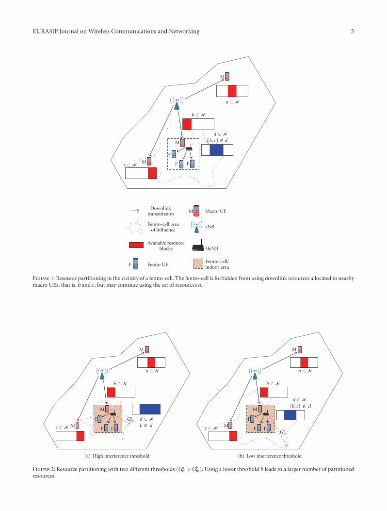
In case the average channel gain between an HeNBand the vulnerable macro UEs exceeds Gth, the HeNB isinstructed to perform resource partitioning by suppressingtransmission on RBs that are reserved by the vulnerablemacro UEs. Clearly, decreasing the value of Ith while keepingPf fixed increases the size of the “exclusion region” andprotects a larger number of macro UEs, as seen in Figure 2.Therefore, the lower the threshold Ith, the more resourcesare partitioned by HeNBs, so that the impact of resourcepartitioning on femto-cell performance increases as Ith
decreases. The simulation results presented in Section 5make use of two different values of Ith such that one translatesto a large exclusion region and the other to a small one.
It is possible that more than one macro UE experiencesheavy interference from more than one HeNB. Supposethat HeNB i causes strong interference to several UEs,as determined by the threshold test (10). Let the set ofmacro UEs exposed to strong interference from HeNB i bedenoted by Ui
aff. The associated measurement and signaling
procedures on how each UE in Uiaff identifies the interfering
HeNB i are detailed in Section 3.3. As per the resourcepartitioning concept, HeNB i must partition resources suchthat it does not cause interference to the set of macro UEsUi
aff. In other words, the resources that are prohibited forHeNB i are in the form
N i =⋃
u ∈ Uiaff
Nu . (11)
We note that the affected macro UEs within Uiaff may be
connected to different macro eNBs, as HeNB i may be withinthe coverage area of several macro-cells.
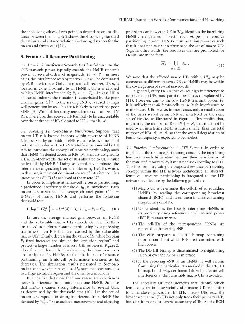
In general, every HeNB that causes high interference tonearby macro UEs must partition resources as explained by(11). However, due to the low HeNB transmit power, Pf,it is unlikely that all femto-cells cause high interference tomany macro UEs. Hence, in most cases, only a small subsetof the users served by an eNB are interfered by the sameset of HeNBs, as illustrated in Figure 1. This implies that,in general, the number of RBs |N i| = Ni that must not beused by an interfering HeNB is much smaller than the totalnumber of RBs, Ni � N , so that the overall degradation offemto-cell capacity is expected to be modest.
3.3. Practical Implementation in LTE Systems. In order toimplement the resource partitioning concept, the interferingfemto-cell needs to be identified and then be informed ofthe restricted resources Ni it must not use according to (11).This involves integrating the proposed resource partitioningconcept within the LTE network architecture. In abstract,femto-cell resource partitioning is integrated to the LTEnetwork architecture by the following procedure.
(1) Macro UE u determines the cell-ID of surroundingHeNBs, by reading the corresponding broadcastchannel (BCH), and stores them in a list containingneighboring cell-IDs.
(2) UE u identifies the heavily interfering HeNBs inits proximity using reference signal received power(RSRP) measurements.
(3) The cell-IDs of the corresponding HeNBs arereported to the serving eNB.
(4) The eNB prepares a DL-HII bitmap containinginformation about which RBs are transmitted withhigh power.
(5) The DL-HII bitmap is disseminated to neighboringH/eNBs over the X2 or S1 interfaces.
(6) If the receiving eNB is an HeNB, it will refrainfrom using the particular RBs marked in the DL-HIIbitmap. In this way, detrimental downlink femto-cellinterference at the vulnerable macro UEs is avoided.
The necessary UE measurements that identify whichfemto-cells are in close vicinity of a macro UE are similarto a handover procedure. In LTE, macro UEs read thebroadcast channel (BCH) not only from their primary eNB,but also from one or several secondary eNBs. As the BCH
EURASIP Journal on Wireless Communications and Networking 5
M
F
F Fc ⊂ NM
d ⊂ N{b, c} /∈ d
b ⊂ N
a ⊂ N
M
Downlinktransmission
Femto-cell areaof influence
Available resourceblocks
Femto UEF
Macro UEM
eNB
HeNB
Femto-cell/indoor area
Figure 1: Resource partitioning in the vicinity of a femto-cell. The femto-cell is forbidden from using downlink resources allocated to nearbymacro UEs, that is, b and c, but may continue using the set of resources a.
M
a ⊂ N
b ⊂ N
M
F
F FMc ⊂ N
Gath d ⊂ N
b /∈ d
(a) High interference threshold
M
a ⊂ N
b ⊂ N
M
F
F FMc ⊂ N
Gath
d ⊂ N{b, c} /∈ d
(b) Low interference threshold
Figure 2: Resource partitioning with two different thresholds (Gath > Gb
th). Using a lower threshold b leads to a larger number of partitionedresources.
6 EURASIP Journal on Wireless Communications and Networking
MME/S-GW
MME/S-GW
(H)eNB (H)eNB
(H)eNB
S1 S1
S1 S1
X2
X2 X2
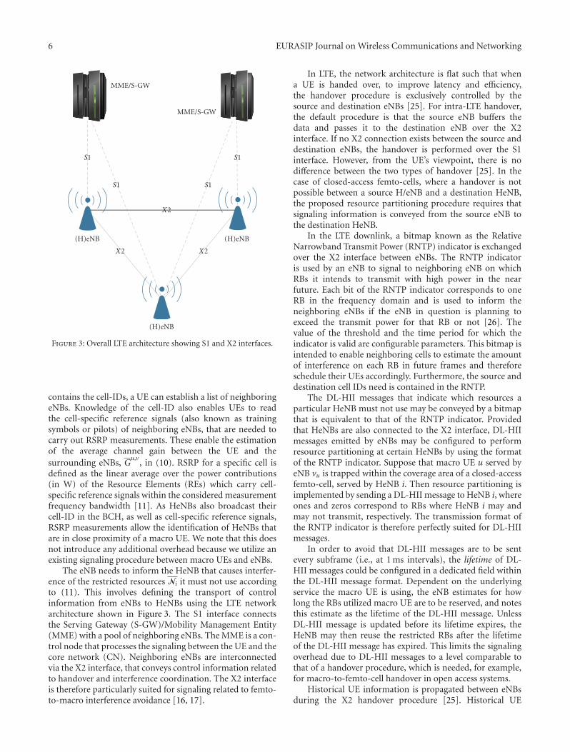
Figure 3: Overall LTE architecture showing S1 and X2 interfaces.
contains the cell-IDs, a UE can establish a list of neighboringeNBs. Knowledge of the cell-ID also enables UEs to readthe cell-specific reference signals (also known as trainingsymbols or pilots) of neighboring eNBs, that are needed tocarry out RSRP measurements. These enable the estimationof the average channel gain between the UE and thesurrounding eNBs, G
u,v, in (10). RSRP for a specific cell is
defined as the linear average over the power contributions(in W) of the Resource Elements (REs) which carry cell-specific reference signals within the considered measurementfrequency bandwidth [11]. As HeNBs also broadcast theircell-ID in the BCH, as well as cell-specific reference signals,RSRP measurements allow the identification of HeNBs thatare in close proximity of a macro UE. We note that this doesnot introduce any additional overhead because we utilize anexisting signaling procedure between macro UEs and eNBs.
The eNB needs to inform the HeNB that causes interfer-ence of the restricted resources Ni it must not use accordingto (11). This involves defining the transport of controlinformation from eNBs to HeNBs using the LTE networkarchitecture shown in Figure 3. The S1 interface connectsthe Serving Gateway (S-GW)/Mobility Management Entity(MME) with a pool of neighboring eNBs. The MME is a con-trol node that processes the signaling between the UE and thecore network (CN). Neighboring eNBs are interconnectedvia the X2 interface, that conveys control information relatedto handover and interference coordination. The X2 interfaceis therefore particularly suited for signaling related to femto-to-macro interference avoidance [16, 17].
In LTE, the network architecture is flat such that whena UE is handed over, to improve latency and efficiency,the handover procedure is exclusively controlled by thesource and destination eNBs [25]. For intra-LTE handover,the default procedure is that the source eNB buffers thedata and passes it to the destination eNB over the X2interface. If no X2 connection exists between the source anddestination eNBs, the handover is performed over the S1interface. However, from the UE’s viewpoint, there is nodifference between the two types of handover [25]. In thecase of closed-access femto-cells, where a handover is notpossible between a source H/eNB and a destination HeNB,the proposed resource partitioning procedure requires thatsignaling information is conveyed from the source eNB tothe destination HeNB.
In the LTE downlink, a bitmap known as the RelativeNarrowband Transmit Power (RNTP) indicator is exchangedover the X2 interface between eNBs. The RNTP indicatoris used by an eNB to signal to neighboring eNB on whichRBs it intends to transmit with high power in the nearfuture. Each bit of the RNTP indicator corresponds to oneRB in the frequency domain and is used to inform theneighboring eNBs if the eNB in question is planning toexceed the transmit power for that RB or not [26]. Thevalue of the threshold and the time period for which theindicator is valid are configurable parameters. This bitmap isintended to enable neighboring cells to estimate the amountof interference on each RB in future frames and thereforeschedule their UEs accordingly. Furthermore, the source anddestination cell IDs need is contained in the RNTP.
The DL-HII messages that indicate which resources aparticular HeNB must not use may be conveyed by a bitmapthat is equivalent to that of the RNTP indicator. Providedthat HeNBs are also connected to the X2 interface, DL-HIImessages emitted by eNBs may be configured to performresource partitioning at certain HeNBs by using the formatof the RNTP indicator. Suppose that macro UE u served byeNB vu is trapped within the coverage area of a closed-accessfemto-cell, served by HeNB i. Then resource partitioning isimplemented by sending a DL-HII message to HeNB i, whereones and zeros correspond to RBs where HeNB i may andmay not transmit, respectively. The transmission format ofthe RNTP indicator is therefore perfectly suited for DL-HIImessages.
In order to avoid that DL-HII messages are to be sentevery subframe (i.e., at 1 ms intervals), the lifetime of DL-HII messages could be configured in a dedicated field withinthe DL-HII message format. Dependent on the underlyingservice the macro UE is using, the eNB estimates for howlong the RBs utilized macro UE are to be reserved, and notesthis estimate as the lifetime of the DL-HII message. UnlessDL-HII message is updated before its lifetime expires, theHeNB may then reuse the restricted RBs after the lifetimeof the DL-HII message has expired. This limits the signalingoverhead due to DL-HII messages to a level comparable tothat of a handover procedure, which is needed, for example,for macro-to-femto-cell handover in open access systems.
Historical UE information is propagated between eNBsduring the X2 handover procedure [25]. Historical UE
EURASIP Journal on Wireless Communications and Networking 7
information consists of the last few cells visited by the UE,together with the time for which the UE was camped at thateNB. The historical information is used to determine theoccurrence of a handover ping-pong between cells. This isalso a source of information that is useful in the contextof resource partitioning. If a UE is camped to the last feweNBs for a short time interval, the resource partitioningprocedure need not be carried out. This can be done to avoidunnecessary signaling.
4. System Level Simulation Setup
4.1. User Distribution and Sectorized eNBs. The simulationarea comprises a two-tier, tessellated hexagonal cell distri-bution. In order to eliminate edge effects with regards tointerference, additional two tiers are simulated. However,statistics are taken only from the central two tiers. The eNBsare placed at the junction of three hexagonal cells, suchthat each cell can be considered as a sector. In this way,each eNB serves three sectors, with each sector reusing allfrequency resources. For each sector, the azimuth antennapattern, A(θ), is described by [24]
A(θ) = −min
[12(
θ
θ3dB
)2
,Am
], (12)
where the θ3dB = 70◦ is the angle from the central lobeat which the gain reduces to half the maximum value andAm = 20 dB is the maximum possible attenuation due tosectorization.
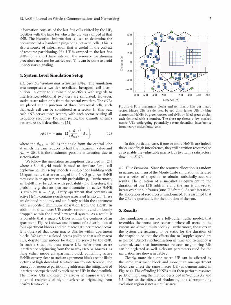
We follow the simulation assumptions described in [24]where a 5 × 5 grid model is used to simulate femto-celldeployment. This setup models a single-floor building with25 apartments that are arranged in a 5 × 5 grid. An HeNBmay exist in an apartment with probability p1. Furthermore,an HeNB may be active with probability p2. Therefore, theprobability p that an apartment contains an active HeNBis given by p = p1p2. Every apartment that contains anactive HeNB contains exactly one associated femto UE. Theseare dropped randomly and uniformly within the apartmentwith a specified minimum separation from the HeNB. Inaddition to this, macro UEs are also randomly and uniformlydropped within the tiered hexagonal system. As a result, itis possible that a macro UE lies within the confines of anapartment. Figure 4 shows one instance of a distribution offour apartment blocks and ten macro UEs per macro sector.It is observed that some macro UEs lie within apartmentblocks. We assume a closed-access policy so that such macroUEs, despite their indoor location, are served by the eNB.In such a situation, these macro UEs suffer from severeinterference originating from the nearby HeNBs. Macro UEslying either inside an apartment block containing activeHeNBs or very close to such an apartment block are the likelyvictims of high downlink femto-to-macro interference. Theconcept of resource partitioning addresses the mitigation ofinterference experienced by such macro UEs in the downlink.The macro UEs indicated by arrows in Figure 4 are thepotential recipients of high interference originating fromnearby femto-cells.
1
3
4
−800 −600 −400 −200 0 200 400 600 800
−600
−400
−200
0
200
400
600
2
5
6
7
89
50 100 150
−520
−500
−480
−460
−440
Dis
tan
ce(m
)
Distance (m)
Figure 4: Four apartment blocks and ten macro UEs per macrosector. Macro UEs are denoted by red dots, femto UEs by bluediamonds, HeNBs by green crosses and eNBs by filled green circles,each denoted with a number. The close-up shows a few markedmacro UEs undergoing potentially severe downlink interferencefrom nearby active femto-cells.
In this particular case, if one or more HeNBs are indeedthe cause of high interference, they will partition resources soas to enable the vulnerable macro UEs to attain a satisfactorydownlink SINR.
4.2. Time Evolution. Since the resource allocation is randomin nature, each run of the Monte Carlo simulation is iteratedover a series of snapshots to obtain statistically accurateresults. The duration of a snapshot is equivalent to theduration of one LTE subframe and the run is allowed toiterate over ten subframes (one LTE frame). At each iteration,the allocation of resources is randomized. It is assumed thatthe UEs are quasistatic for the duration of the run.
5. Results
The simulation is run for a full-buffer traffic model, thatresembles the worst case scenario where all users in thesystem are active simultaneously. Furthermore, the users inthe system are assumed to be static for the duration ofthe snapshot, so that the effects due to Doppler spread areneglected. Perfect synchronization in time and frequency isassumed, such that interference between neighboring RBscan be neglected as well. Relevant parameters used for thesimulation are shown in Table 3.
Clearly, more than one macro UE can be affected bythe same apartment block and more than one apartmentblock can affect the same macro UE (as demonstrated inFigure 4). The offending HeNBs must then perform resourcepartitioning using the method described in Sections 3.2 and3.3. Due to the effects of shadowing, the correspondingexclusion region is not a circular area.
8 EURASIP Journal on Wireless Communications and Networking
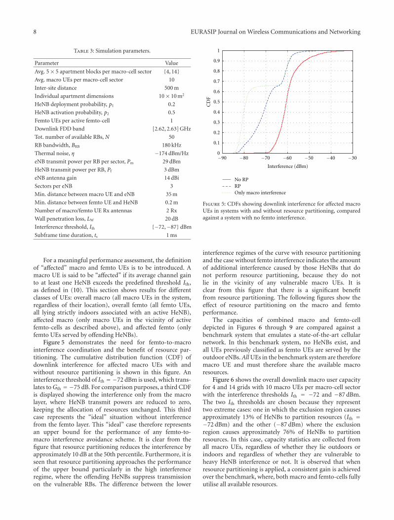
Table 3: Simulation parameters.
Parameter Value
Avg. 5× 5 apartment blocks per macro-cell sector {4, 14}Avg. macro UEs per macro-cell sector 10
Inter-site distance 500 m
Individual apartment dimensions 10× 10 m2
HeNB deployment probability, p1 0.2
HeNB activation probability, p2 0.5
Femto UEs per active femto-cell 1
Downlink FDD band [2.62, 2.63] GHz
Tot. number of available RBs, N 50
RB bandwidth, BRB 180 kHz
Thermal noise, η −174 dBm/Hz
eNB transmit power per RB per sector, Pm 29 dBm
HeNB transmit power per RB, Pf 3 dBm
eNB antenna gain 14 dBi
Sectors per eNB 3
Min. distance between macro UE and eNB 35 m
Min. distance between femto UE and HeNB 0.2 m
Number of macro/femto UE Rx antennas 2 Rx
Wall penetration loss, LW 20 dB
Interference threshold, Ith {−72,−87} dBm
Subframe time duration, ts 1 ms
For a meaningful performance assessment, the definitionof “affected” macro and femto UEs is to be introduced. Amacro UE is said to be “affected” if its average channel gainto at least one HeNB exceeds the predefined threshold Ith,as defined in (10). This section shows results for differentclasses of UEs: overall macro (all macro UEs in the system,regardless of their location), overall femto (all femto UEs,all lying strictly indoors associated with an active HeNB),affected macro (only macro UEs in the vicinity of activefemto-cells as described above), and affected femto (onlyfemto UEs served by offending HeNBs).
Figure 5 demonstrates the need for femto-to-macrointerference coordination and the benefit of resource par-titioning. The cumulative distribution function (CDF) ofdownlink interference for affected macro UEs with andwithout resource partitioning is shown in this figure. Aninterference threshold of Ith = −72 dBm is used, which trans-lates to Gth = −75 dB. For comparison purposes, a third CDFis displayed showing the interference only from the macrolayer, where HeNB transmit powers are reduced to zero,keeping the allocation of resources unchanged. This thirdcase represents the “ideal” situation without interferencefrom the femto layer. This “ideal” case therefore representsan upper bound for the performance of any femto-to-macro interference avoidance scheme. It is clear from thefigure that resource partitioning reduces the interference byapproximately 10 dB at the 50th percentile. Furthermore, it isseen that resource partitioning approaches the performanceof the upper bound particularly in the high interferenceregime, where the offending HeNBs suppress transmissionon the vulnerable RBs. The difference between the lower
−90 −80 −70 −60 −50 −40 −300
1
0.1
0.2
0.3
0.4
0.5
0.6
0.7
0.8
0.9
Interference (dBm)
CD
F
No RPRPOnly macro interference
Figure 5: CDFs showing downlink interference for affected macroUEs in systems with and without resource partitioning, comparedagainst a system with no femto interference.
interference regimes of the curve with resource partitioningand the case without femto interference indicates the amountof additional interference caused by those HeNBs that donot perform resource partitioning, because they do notlie in the vicinity of any vulnerable macro UEs. It isclear from this figure that there is a significant benefitfrom resource partitioning. The following figures show theeffect of resource partitioning on the macro and femtoperformance.
The capacities of combined macro and femto-celldepicted in Figures 6 through 9 are compared against abenchmark system that emulates a state-of-the-art cellularnetwork. In this benchmark system, no HeNBs exist, andall UEs previously classified as femto UEs are served by theoutdoor eNBs.All UEs in the benchmark system are thereforemacro UE and must therefore share the available macroresources.
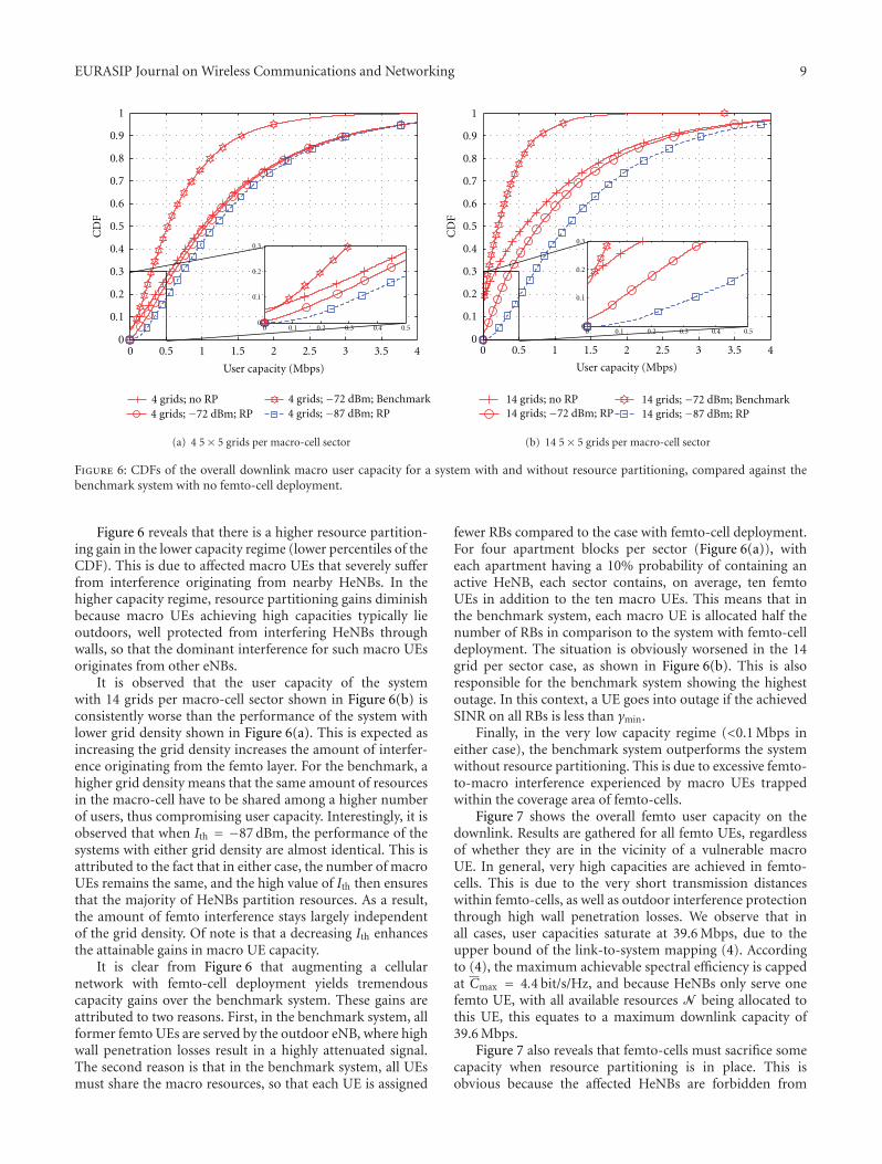
Figure 6 shows the overall downlink macro user capacityfor 4 and 14 grids with 10 macro UEs per macro-cell sectorwith the interference thresholds Ith = −72 and −87 dBm.The two Ith thresholds are chosen because they representtwo extreme cases: one in which the exclusion region causesapproximately 13% of HeNBs to partition resources (Ith =−72 dBm) and the other (−87 dBm) where the exclusionregion causes approximately 76% of HeNBs to partitionresources. In this case, capacity statistics are collected fromall macro UEs, regardless of whether they lie outdoors orindoors and regardless of whether they are vulnerable toheavy HeNB interference or not. It is observed that whenresource partitioning is applied, a consistent gain is achievedover the benchmark, where, both macro and femto-cells fullyutilise all available resources.
EURASIP Journal on Wireless Communications and Networking 9
0 0.5 1 1.5 2 2.5 3 3.5 40
0.1
0.2
0.3
0.4
0.5
0.6
0.7
0.8
0.9
1
CD
F
0
0.1
0.2
0.3
0.4 0.50 0.1 0.2 0.3
4 grids; no RP4 grids; −72 dBm; RP
4 grids; −72 dBm; Benchmark4 grids; −87 dBm; RP
User capacity (Mbps)
(a) 4 5× 5 grids per macro-cell sector
0 0.5 1 1.5 2 2.5 3 3.5 40
0.1
0.2
0.3
0.4
0.5
0.6
0.7
0.8
0.9
1
CD
F
0 0.1 0.2 0.3 0.4 0.50
0.1
0.2
0.3
User capacity (Mbps)
14 grids; no RP14 grids; −72 dBm; RP
14 grids; −72 dBm; Benchmark14 grids; −87 dBm; RP
(b) 14 5× 5 grids per macro-cell sector
Figure 6: CDFs of the overall downlink macro user capacity for a system with and without resource partitioning, compared against thebenchmark system with no femto-cell deployment.
Figure 6 reveals that there is a higher resource partition-ing gain in the lower capacity regime (lower percentiles of theCDF). This is due to affected macro UEs that severely sufferfrom interference originating from nearby HeNBs. In thehigher capacity regime, resource partitioning gains diminishbecause macro UEs achieving high capacities typically lieoutdoors, well protected from interfering HeNBs throughwalls, so that the dominant interference for such macro UEsoriginates from other eNBs.
It is observed that the user capacity of the systemwith 14 grids per macro-cell sector shown in Figure 6(b) isconsistently worse than the performance of the system withlower grid density shown in Figure 6(a). This is expected asincreasing the grid density increases the amount of interfer-ence originating from the femto layer. For the benchmark, ahigher grid density means that the same amount of resourcesin the macro-cell have to be shared among a higher numberof users, thus compromising user capacity. Interestingly, it isobserved that when Ith = −87 dBm, the performance of thesystems with either grid density are almost identical. This isattributed to the fact that in either case, the number of macroUEs remains the same, and the high value of Ith then ensuresthat the majority of HeNBs partition resources. As a result,the amount of femto interference stays largely independentof the grid density. Of note is that a decreasing Ith enhancesthe attainable gains in macro UE capacity.
It is clear from Figure 6 that augmenting a cellularnetwork with femto-cell deployment yields tremendouscapacity gains over the benchmark system. These gains areattributed to two reasons. First, in the benchmark system, allformer femto UEs are served by the outdoor eNB, where highwall penetration losses result in a highly attenuated signal.The second reason is that in the benchmark system, all UEsmust share the macro resources, so that each UE is assigned
fewer RBs compared to the case with femto-cell deployment.For four apartment blocks per sector (Figure 6(a)), witheach apartment having a 10% probability of containing anactive HeNB, each sector contains, on average, ten femtoUEs in addition to the ten macro UEs. This means that inthe benchmark system, each macro UE is allocated half thenumber of RBs in comparison to the system with femto-celldeployment. The situation is obviously worsened in the 14grid per sector case, as shown in Figure 6(b). This is alsoresponsible for the benchmark system showing the highestoutage. In this context, a UE goes into outage if the achievedSINR on all RBs is less than γmin.
Finally, in the very low capacity regime (<0.1 Mbps ineither case), the benchmark system outperforms the systemwithout resource partitioning. This is due to excessive femto-to-macro interference experienced by macro UEs trappedwithin the coverage area of femto-cells.
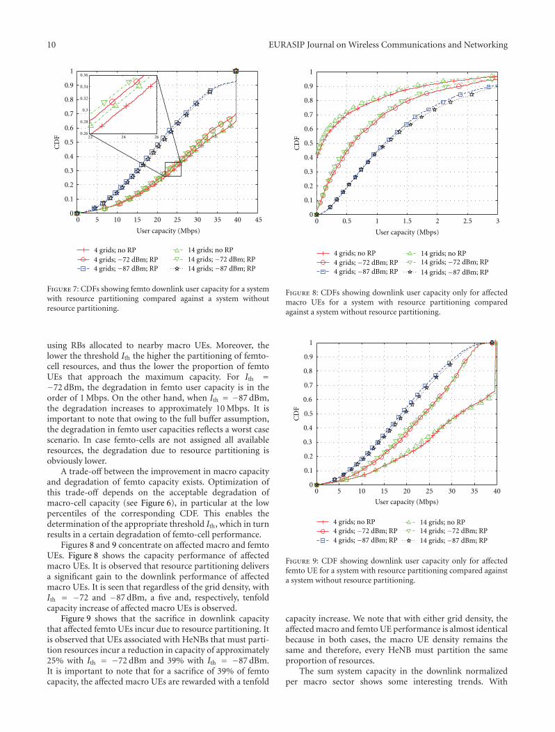
Figure 7 shows the overall femto user capacity on thedownlink. Results are gathered for all femto UEs, regardlessof whether they are in the vicinity of a vulnerable macroUE. In general, very high capacities are achieved in femto-cells. This is due to the very short transmission distanceswithin femto-cells, as well as outdoor interference protectionthrough high wall penetration losses. We observe that inall cases, user capacities saturate at 39.6 Mbps, due to theupper bound of the link-to-system mapping (4). Accordingto (4), the maximum achievable spectral efficiency is cappedat Cmax = 4.4 bit/s/Hz, and because HeNBs only serve onefemto UE, with all available resources N being allocated tothis UE, this equates to a maximum downlink capacity of39.6 Mbps.
Figure 7 also reveals that femto-cells must sacrifice somecapacity when resource partitioning is in place. This isobvious because the affected HeNBs are forbidden from
10 EURASIP Journal on Wireless Communications and Networking
0 5 10 15 20 25 30 35 40 450
0.1
0.2
0.3
0.4
0.5
0.6
0.7
0.8
0.9
1
User capacity (Mbps)
CD
F
4 grids; no RP4 grids; −72 dBm; RP4 grids; −87 dBm; RP
14 grids; no RP14 grids; −72 dBm; RP14 grids; −87 dBm; RP
22 24 260.26
0.28
0.3
0.32
0.34
0.36
Figure 7: CDFs showing femto downlink user capacity for a systemwith resource partitioning compared against a system withoutresource partitioning.
using RBs allocated to nearby macro UEs. Moreover, thelower the threshold Ith the higher the partitioning of femto-cell resources, and thus the lower the proportion of femtoUEs that approach the maximum capacity. For Ith =−72 dBm, the degradation in femto user capacity is in theorder of 1 Mbps. On the other hand, when Ith = −87 dBm,the degradation increases to approximately 10 Mbps. It isimportant to note that owing to the full buffer assumption,the degradation in femto user capacities reflects a worst casescenario. In case femto-cells are not assigned all availableresources, the degradation due to resource partitioning isobviously lower.
A trade-off between the improvement in macro capacityand degradation of femto capacity exists. Optimization ofthis trade-off depends on the acceptable degradation ofmacro-cell capacity (see Figure 6), in particular at the lowpercentiles of the corresponding CDF. This enables thedetermination of the appropriate threshold Ith, which in turnresults in a certain degradation of femto-cell performance.
Figures 8 and 9 concentrate on affected macro and femtoUEs. Figure 8 shows the capacity performance of affectedmacro UEs. It is observed that resource partitioning deliversa significant gain to the downlink performance of affectedmacro UEs. It is seen that regardless of the grid density, withIth = −72 and −87 dBm, a five and, respectively, tenfoldcapacity increase of affected macro UEs is observed.
Figure 9 shows that the sacrifice in downlink capacitythat affected femto UEs incur due to resource partitioning. Itis observed that UEs associated with HeNBs that must parti-tion resources incur a reduction in capacity of approximately25% with Ith = −72 dBm and 39% with Ith = −87 dBm.It is important to note that for a sacrifice of 39% of femtocapacity, the affected macro UEs are rewarded with a tenfold
0 0.5 1 1.5 2 2.5 30
0.1
0.2
0.3
0.4
0.5
0.6
0.7
0.8
0.9
1
User capacity (Mbps)
CD
F
4 grids; no RP4 grids; −72 dBm; RP4 grids; −87 dBm; RP
14 grids; no RP14 grids; −72 dBm; RP
14 grids; −87 dBm; RP
Figure 8: CDFs showing downlink user capacity only for affectedmacro UEs for a system with resource partitioning comparedagainst a system without resource partitioning.
0 5 10 15 20 25 30 35 400
0.1
0.2
0.3
0.4
0.5
0.6
0.7
0.8
0.9
1
User capacity (Mbps)
CD
F
4 grids; no RP4 grids; −72 dBm; RP4 grids; −87 dBm; RP
14 grids; no RP14 grids; −72 dBm; RP14 grids; −87 dBm; RP
Figure 9: CDF showing downlink user capacity only for affectedfemto UE for a system with resource partitioning compared againsta system without resource partitioning.
capacity increase. We note that with either grid density, theaffected macro and femto UE performance is almost identicalbecause in both cases, the macro UE density remains thesame and therefore, every HeNB must partition the sameproportion of resources.
The sum system capacity in the downlink normalizedper macro sector shows some interesting trends. With
EURASIP Journal on Wireless Communications and Networking 11
Table 4: Femto UE capacity degradation and macro UE capacityimprovement.
Ith valueOverall femtoUE degradation
Affected macroUE improvement
Affected femtoUE degradation
−72 dBm 1 Mbps 5x 25%
−87 dBm 10 Mbps 10x 39%
a grid density of 4 grids per macro-cell sector and Ith =−72 dBm, the use of resource partitioning results in anaffected macro UE capacity increase of 6.4% at the costof a 2.8% degradation in femto capacity. However, whenIth = −87 dBm, a 14.2% increase in macro capacity isaccompanied by a 29.6% decrease in femto capacity. Thesituation is different for the case when the grid density isincreased to 14 grids per macro sector. When Ith = −72 dBm,a 15.7% increase in macro capacity is attained at a theexpense of a 2.8% decrease in femto capacity. For Ith =−87 dBm, resource partitioning results in a 53.2% increase inaffected macro UE capacity with a 25.1% decrease in femtocapacity. This shows that with decreasing grid densities,a relatively high interference threshold Ith becomes moreeffective.
For convenience, the femto UE degradation and macroUE improvement in capacity through the use of resourcepartitioning are listed in Table 4.
6. Summary and Conclusion
Femto-cell deployment poses a viable complement to cel-lular networks. Operators need to bear low cost in theirdeployment because they are installed directly by the usersthemselves. Furthermore, because they share both, the radioaccess scheme and the frequency band with eNBs, they arecompatible with legacy UEs. Aside from these benefits, acellular network stands to significantly gain in overall systemthroughput through the widespread deployment of HeNBs.Not only do HeNBs improve indoor coverage, bringingbroadband-like experience directly to the handset, but theyalso offload resources from the eNB that can be utilized toimprove coverage to outdoor users.
It has been seen that in a closed-access system, macro UEslying in the proximity of femto-cells experience at least asmuch downlink interference from HeNBs as they do fromeNBs. It has been demonstrated that by introducing LTE-specific resource partitioning, the capacity of such macroUEs can be boosted by a factor of ten. The cost incurred byfemto UE in doing so is minimal as they lose less than half oftheir capacity (which is more than one order of magnitudehigher than macro UE downlink capacity). Users thereforeexperience a very high throughput inside femto-cells dueto the favorable channel conditions and continue to do soeven in the presence of resource partitioning. Introducingresource partitioning to a closed-access system with femto-cell deployment substantially boosts the sum system capacitywhile ensuring reliable macro-cell operation.
Acknowledgments
Initial parts of this work were supported by DFG GrantHA 3570/2-1 as part of program SPP-1163 (adaptabilityin heterogeneous communication networks with wirelessaccess—AKOM) while some latter parts of this work havebeen performed within the framework of the CELTICproject CP5-026 WINNER+. Harald Haas acknowledges theScottish Funding Council support of his position withinthe Edinburgh Research Partnership in Engineering andMathematics between the University of Edinburgh andHeriot Watt University.
References
[1] M.-S. Alouini and A. J. Goldsmith, “Area spectral efficiency ofcellular mobile radio systems,” IEEE Transactions on VehicularTechnology, vol. 48, no. 4, pp. 1047–1066, 1999.
[2] T. Nihtila, “Increasing femto cell throughput with HSDPAusing higher order modulation,” in Proceedings of the IEEEInternational Networking and Communications Conference(INCC ’08), pp. 49–53, Lahore, Pakistan, May 2008.
[3] V. Chandrasekhar, J. G. Andrews, and A. Gatherer, “Femtocellnetworks: a survey,” IEEE Communications Magazine, vol. 46,no. 9, pp. 59–67, 2008.
[4] Z. Bharucha, I. Cosovic, H. Haas, and G. Auer, “Throughputenhancement through femto-cell deployment,” in Proceedingsof the 7th IEEE International Workshop on Multi-CarrierSystems & Solutions (MC-SS ’09), pp. 311–319, Herrsching,Germany, May 2009.
[5] Z. Bharucha, H. Haas, A. Saul, and G. Auer, “Through-put enhancement through femto-cell deployment,” EuropeanTransactions on Telecommunications, vol. 21, no. 4, 2010.
[6] M. Etoh, T. Ohya, and Y. Nakayama, “Energy consumptionissues on mobile network systems,” in Proceedings of theInternational Symposium on Applications and the Internet(SAINT ’08), pp. 365–368, IEEE, Turku, Finland, July-August2008.
[7] H. Haas and G. J. R. Povey, “Capacity analysis of a TDDunderlay applicable for UMTS,” in Proceedings of the 10thIEEE International Symposium on Personal, Indoor and MobileRadio Communications (PIMRC ’99), p. A6-4, Osaka, Japan,September 1999.
[8] H. Haas and G. J. R. Povey, “A capacity investigation on UTRA-TDD utilising underused UTRA-FDD uplink resources,” inProceedings of the IEE Colloquium on UMTS Terminals andSoftware Radio, pp. 1–7, Glasgow, Scotland, April 1999, Ref.no. 1999/055.
[9] P. K. Jain, H. Haas, and S. McLaughlin, “Capacity enhance-ment using ad hoc pico-cells and TDD underlay,” in Proceed-ings of the 17th IEEE International Symposium on Personal,Indoor and Mobile Radio Communications (PIMRC ’06), pp.1–5, Helsinki, Finland, September 2006.
[10] X. Yang, G. Feng, and C. K. Siew, “Call admission controlfor multi-service mobile networks with bandwidth asymmetrybetween uplink and downlink,” in Proceedings of the IEEEGlobal Telecommunications Conference (GLOBECOM ’04), vol.5, pp. 3285–3289, November-December 2004.
[11] 3GPP, “Physical Channels and Modulation (Release 8),”3GPP TS 36.211 V 8.2.0, March 2008, http://www.3gpp.org/ftp/Specs.
[12] D. Lopez-Perez, A. Valcarce, G. De La Roche, and J. Zhang,“OFDMA femtocells: a roadmap on interference avoidance,”
12 EURASIP Journal on Wireless Communications and Networking
IEEE Communications Magazine, vol. 47, no. 9, pp. 41–48,2009.
[13] H. Claussen, “Performance of macro- and co-channel femto-cells in a hierarchical cell structure,” in Proceedings of the 18thIEEE International Symposium on Personal, Indoor and MobileRadio Communications (PIMRC ’07), pp. 1–5, Athens, Greece,September 2007.
[14] L. T. W. Ho and H. Claussen, “Effects of user-deployed, co-channel femtocells on the call drop probability in a residentialscenario,” in Proceedings of the 18th IEEE International Sym-posium on Personal, Indoor and Mobile Radio Communications(PIMRC ’07), pp. 1–5, Athens, Greece, September 2007.
[15] V. Chandrasekhar and J. Andrews, “Uplink capacity andinterference avoidance for two-tier femtocell networks,” IEEETransactions on Wireless Communications, vol. 8, no. 7, pp.3498–3509, 2009.
[16] 3GPP, “X2 General Aspects and Principles (Release 8),”3GPP TS 36.420 V8.0.0, December 2007, http://www.3gpp.org/ftp/Specs.
[17] 3GPP, “X2 Application Protocol (X2AP) (Release 8),” 3GPP TS36.423 V8.2.0, June 2008, http://www.3gpp.org/ftp/Specs.
[18] T. S. Rappaport, Wireless Communications: Principles andPractice, Prentice Hall, Upper Saddle River, NJ, USA, 2ndedition, 2001.
[19] 3GPP, “Evolved Universal Terrestrial Radio Access (E-UTRA);Radio Frequency (RF) System Scenarios,” 3GPP TR 36.942 V8.2.0, May 2009, http://www.3gpp.org/ftp/Specs.
[20] A. Persson, T. Ottosson, A. Saul, G. Auer, and M. Afgani,“On the performance of inter-sector scheduling in OFDMAsystems,” in Proceedings of the 11th International OFDMWorkshop (InOWo ’06), Hamburg, Germany, August 2006.
[21] ITU-R Working Party 5D (WP5D)—IMT Systems, “Report ofcorrespondence group for IMT.EVAL,” Tech. Rep. 124, Dubai,United Arab Emirates, May 2008.
[22] W. Wang, T. Ottosson, M. Sternad, A. Ahlen, and A. Svensson,“Impact of multiuser diversity and channel variability onadaptive OFDM,” in Proceedings of the 58th IEEE VehicularTechnology Conference (VTC ’03), pp. 547–551, Orlando, Fla,USA, October 2003.
[23] NTT DOCOMO, “New Evaluation Models (Micro Cell,Indoor, Rural/High-Speed),” 3GPP TSG RAN WG1 R1-082713, July 2008, http://www.3gpp.org/ftp/tsg ran/WG1RL1/TSGR1 53b/Docs.
[24] 3GPP, “Simulation Assumptions and Parameters for FDDHeNB RF Requirements,” 3GPP TSG RAN WG4 R4-092042,May 2008, http://www.3gpp.org/ftp/Specs.
[25] S. Sesia, I. Toufik, and M. Baker, Eds., LTE—The UMTS LongTerm Evolution: From Theory to Practice, John Wiley & Sons,New York, NY, USA, 1st edition, 2009.
[26] 3GPP, “Evolved Universal Terrestrial Radio Access (E-UTRA);Physical Layer Procedures (Release 8),” 3GPP TS 36.213 V8.8.0, September 2009, http://www.3gpp.org/ftp/Specs.

![UBS-21-92-028 Femto Cell Macro Layer Study · 2012-03-14 · the Macro network (as shown in [15] without traffic migration) implies that there must be a ‘cross over’ point, where,](https://img.pdfslide.us/doc/110x75/5eba9645d951e60b8f406c49/ubs-21-92-028-femto-cell-macro-layer-study-2012-03-14-the-macro-network-as-shown.jpg)