Embed Size (px)
Citation preview
National Aeronautics and Space Administration
www.nasa.gov 1
Dynamic Modeling of Supersonic Propulsion Systems for
Aero-Propulso-Servo-Elasticity Analysis
George Kopasakis
NASA Glenn Research Center
Cleveland Ohio
NASA Propulsion, Controls and Diagnostics Workshop
Sept. 16-17, 2015, Cleveland, OH
NASA Advanced Air Vehicles Program – Commercial Supersonic
Technology Project - AeroServoElasticity
National Aeronautics and Space Administration
www.nasa.gov 2
Team Members
GRC
George Kopasakis
Joseph W. Connolly
Noulie Theofylaktos
Jonathan Seidel
LaRC
Walter Silva & team
National Aeronautics and Space Administration
www.nasa.gov 3
Outline
• APSE Goals
• AeroServoElastic System Dynamic Modeling
• Propulsion System Dynamic modeling
• APSE Integration
National Aeronautics and Space Administration
www.nasa.gov4
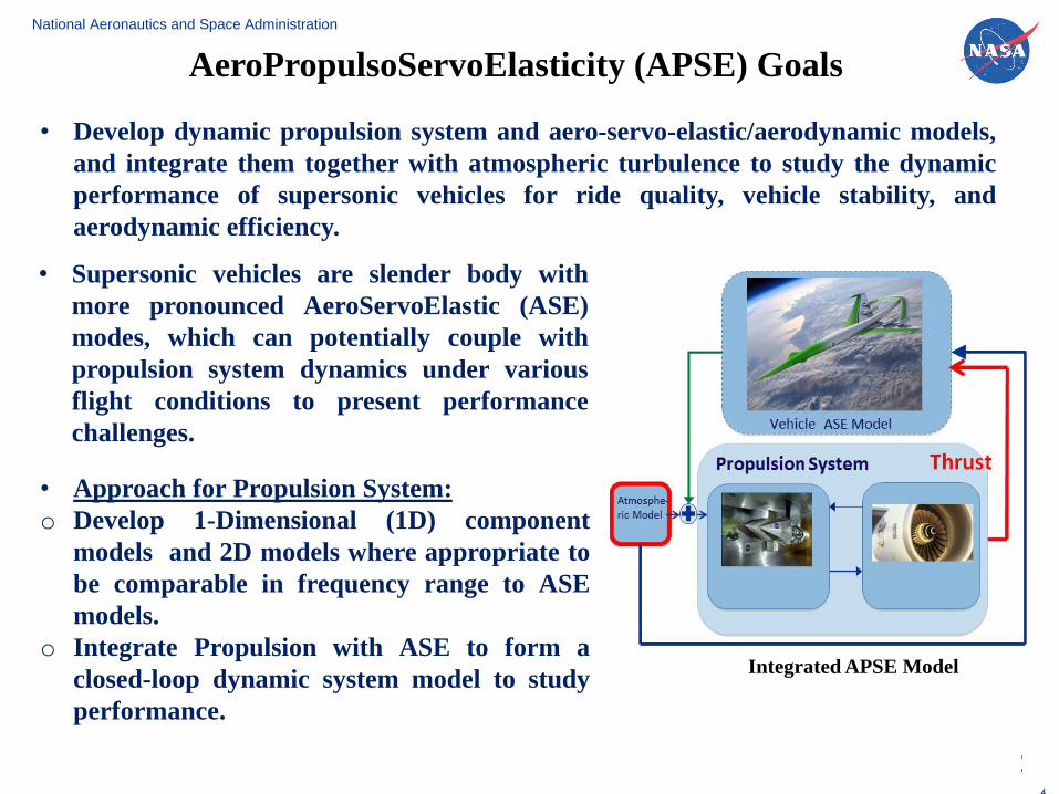
• Develop dynamic propulsion system and aero-servo-elastic/aerodynamic models,
and integrate them together with atmospheric turbulence to study the dynamic
performance of supersonic vehicles for ride quality, vehicle stability, and
aerodynamic efficiency.
AeroPropulsoServoElasticity (APSE) Goals
Integrated APSE Model
• Supersonic vehicles are slender body with
more pronounced AeroServoElastic (ASE)
modes, which can potentially couple with
propulsion system dynamics under various
flight conditions to present performance
challenges.
• Approach for Propulsion System:
o Develop 1-Dimensional (1D) component
models and 2D models where appropriate to
be comparable in frequency range to ASE
models.
o Integrate Propulsion with ASE to form a
closed-loop dynamic system model to study
performance.
4
National Aeronautics and Space Administration
www.nasa.gov 5
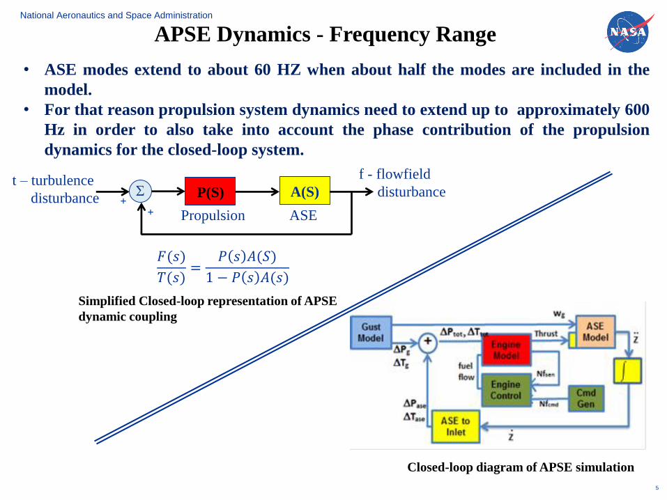
APSE Dynamics - Frequency Range
Propulsion
A(S)P(S)St – turbulence
disturbance
ASE
f - flowfield
disturbance
++
𝐹(𝑠)
𝑇(𝑠)=
𝑃 𝑠 𝐴(𝑆)
1 − 𝑃 𝑠 𝐴(𝑠)
Closed-loop diagram of APSE simulation
Simplified Closed-loop representation of APSE
dynamic coupling
• ASE modes extend to about 60 HZ when about half the modes are included in the
model.
• For that reason propulsion system dynamics need to extend up to approximately 600
Hz in order to also take into account the phase contribution of the propulsion
dynamics for the closed-loop system.
National Aeronautics and Space Administration
www.nasa.gov 6
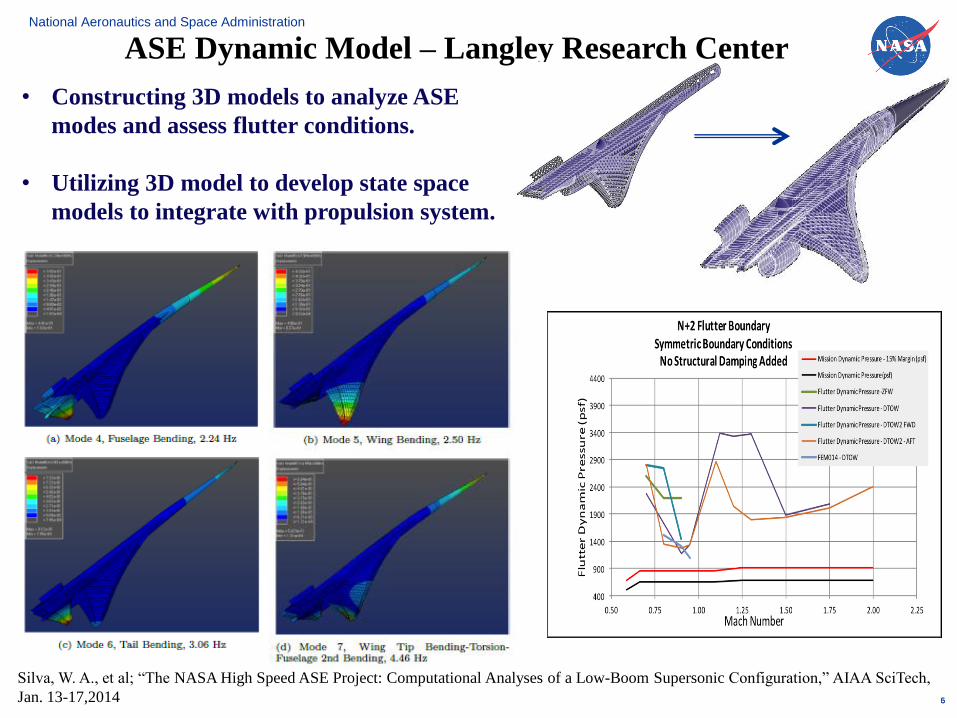
• Constructing 3D models to analyze ASE
modes and assess flutter conditions.
• Utilizing 3D model to develop state space
models to integrate with propulsion system.
5
ASE Dynamic Model – Langley Research Center
Silva, W. A., et al; “The NASA High Speed ASE Project: Computational Analyses of a Low-Boom Supersonic Configuration,” AIAA SciTech,
Jan. 13-17,2014
National Aeronautics and Space Administration
www.nasa.gov 7
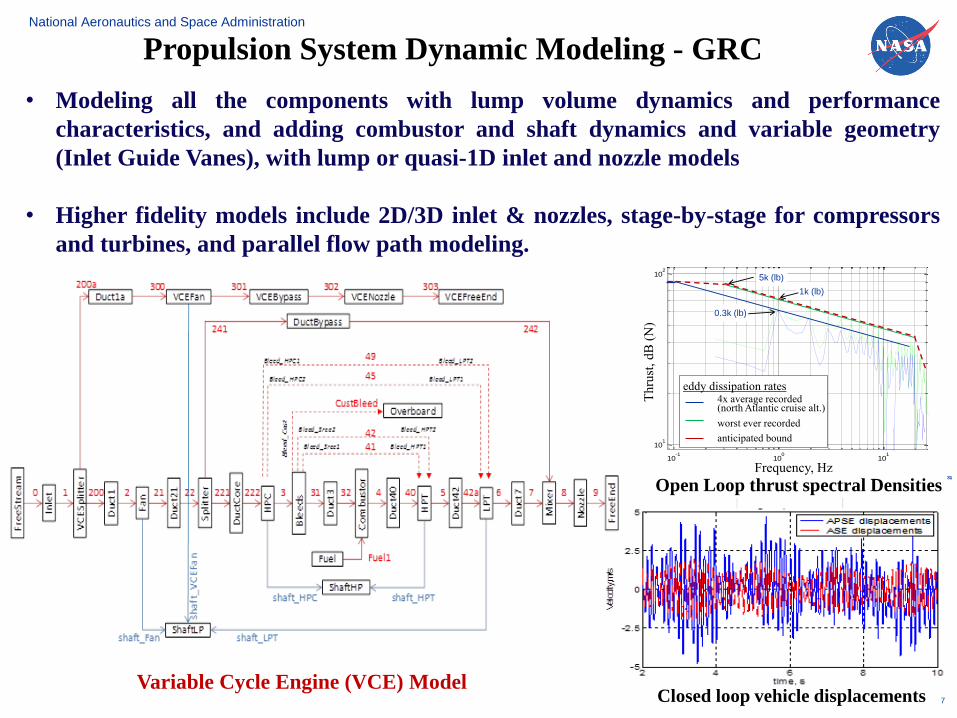
Propulsion System Dynamic Modeling - GRC
Variable Cycle Engine (VCE) Model
• Modeling all the components with lump volume dynamics and performance
characteristics, and adding combustor and shaft dynamics and variable geometry
(Inlet Guide Vanes), with lump or quasi-1D inlet and nozzle models
• Higher fidelity models include 2D/3D inlet & nozzles, stage-by-stage for compressors
and turbines, and parallel flow path modeling.
3131
10-1
100
101
101
102
Frequency, Hz
Thru
st,
dB
NT
hru
st,
dB
(N
)
Frequency, Hz
eddy dissipation rates4x average recorded (north Atlantic cruise alt.)
worst ever recorded
anticipated bound
5k (lb)
0.3k (lb)
1k (lb)
Open Loop thrust spectral Densities
Closed loop vehicle displacements
National Aeronautics and Space Administration
www.nasa.gov 8
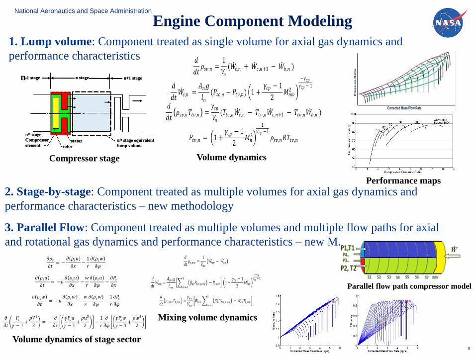
Engine Component Modeling
1. Lump volume: Component treated as single volume for axial gas dynamics and
performance characteristics 𝑑
𝑑𝑡𝜌𝑠𝑣 ,𝑛 =
1
𝑉𝑛(𝑊
𝑐 ,𝑛 + 𝑊 𝑐 ,𝑛+1 − 𝑊
𝑏 ,𝑛 )
𝑑
𝑑𝑡𝑊
𝑐 ,𝑛 =𝐴𝑛𝑔
𝑙𝑛(𝑃𝑡𝑐 ,𝑛 − 𝑃𝑡𝑣 ,𝑛) 1 +
𝛾𝑐𝑝 − 1
2𝑀𝑚𝑣
2
−𝛾𝑐𝑝𝛾𝑐𝑝 − 1
𝑑
𝑑𝑡 𝜌𝑠𝑣 ,𝑛𝑇𝑡𝑣 ,𝑛 =
𝛾𝑐𝑝
𝑉𝑛(𝑇𝑡𝑐 ,𝑛𝑊
𝑐 ,𝑛 − 𝑇𝑡𝑣 ,𝑛𝑊 𝑐 ,𝑛+1 − 𝑇𝑡𝑣 ,𝑛𝑊
𝑏 ,𝑛 )
𝑃𝑡𝑣 ,𝑛 = 1 +𝛾𝑐𝑝 − 1
2𝑀𝑛
2
1𝛾𝑐𝑝 −1
𝜌𝑠𝑣 ,𝑛𝑅𝑇𝑡𝑣 ,𝑛
Volume dynamics
Performance maps
n+1 stage
1n,cW
n,cW
n,tcPn,tvP
n,tcTn,tvT
,Vn
,An
nl
n-1 stage n stage
nth stage equivalent
lump volume
nth stage
Compressor
element rotor
stator
n+1 stage
1n,cW
n,cW
n,tcPn,tvP
n,tcTn,tvT
,Vn
,An
nl
n-1 stage n stage
nth stage equivalent
lump volume
nth stage
Compressor
element rotor
stator
Figure 1 – Schematic of nth
Compressor Stage Compressor stage
n
Parallel flow path compressor model
2. Stage-by-stage: Component treated as multiple volumes for axial gas dynamics and
performance characteristics – new methodology
3. Parallel Flow: Component treated as multiple volumes and multiple flow paths for axial
and rotational gas dynamics and performance characteristics – new M.𝑑
𝑑𝑡𝜌𝑠,𝑚𝑣 =
1
𝑉𝑚𝑣
𝑊 𝑚𝑣 − 𝑊
𝑐𝑏
𝑑
𝑑𝑡𝑊
𝑚𝑣 =𝐴𝑚𝑣𝑔
𝑙𝑚𝑣
𝛽𝑚𝑃𝑡𝑚 ,𝑛=𝑘 𝑞
𝑚=1− 𝑃𝑡 ,𝑚𝑣 1 +
𝛾𝑐𝑝 − 1
2𝑀𝑚𝑣
2
−𝛾𝑐𝑝𝛾𝑐𝑝 − 1
𝑑
𝑑𝑡 𝜌𝑠,𝑚𝑣𝑇𝑡 ,𝑚𝑣 =
𝛾𝑚𝑣
𝑉𝑚𝑣
𝑊 𝑚𝑣 𝛽𝑚
2 𝑇𝑡𝑚 ,𝑛=𝑘 𝑞
𝑚=1− 𝑊
𝑐𝑏𝑇𝑡 ,𝑚𝑣
Mixing volume dynamics
Volume dynamics of stage sector
𝜕𝜌𝑠
𝜕𝑡= −
𝜕(𝜌𝑠𝑢)
𝜕𝑥−
1
𝑟
𝜕(𝜌𝑠𝑤)
𝜕𝜑
(16)
𝜕(𝜌𝑠𝑢)
𝜕𝑡= −𝑢
𝜕(𝜌𝑠𝑢)
𝜕𝑥−
𝑤
𝑟
𝜕(𝜌𝑠𝑢)
𝜕𝜑−
𝜕𝑃𝑠𝜕𝑥
(17)
𝜕(𝜌𝑠𝑤)
𝜕𝑡= −𝑢
𝜕(𝜌𝑠𝑤)
𝜕𝑥−
𝑤
𝑟
𝜕(𝜌𝑠𝑤)
𝜕𝜑−
1
𝑟
𝜕𝑃𝑠𝜕𝜑
(18)
𝜕
𝜕𝑡
𝑃𝑠𝛾 − 1
+𝜌𝑉2
2 = −
𝜕
𝜕𝑥
𝛾𝑃𝑠𝑢
𝛾 − 1+
𝜌𝑢3
2 −
1
𝑟
𝜕
𝜕𝜑
𝛾𝑃𝑠𝑤
𝛾 − 1+
𝜌𝑤3
2
(19)
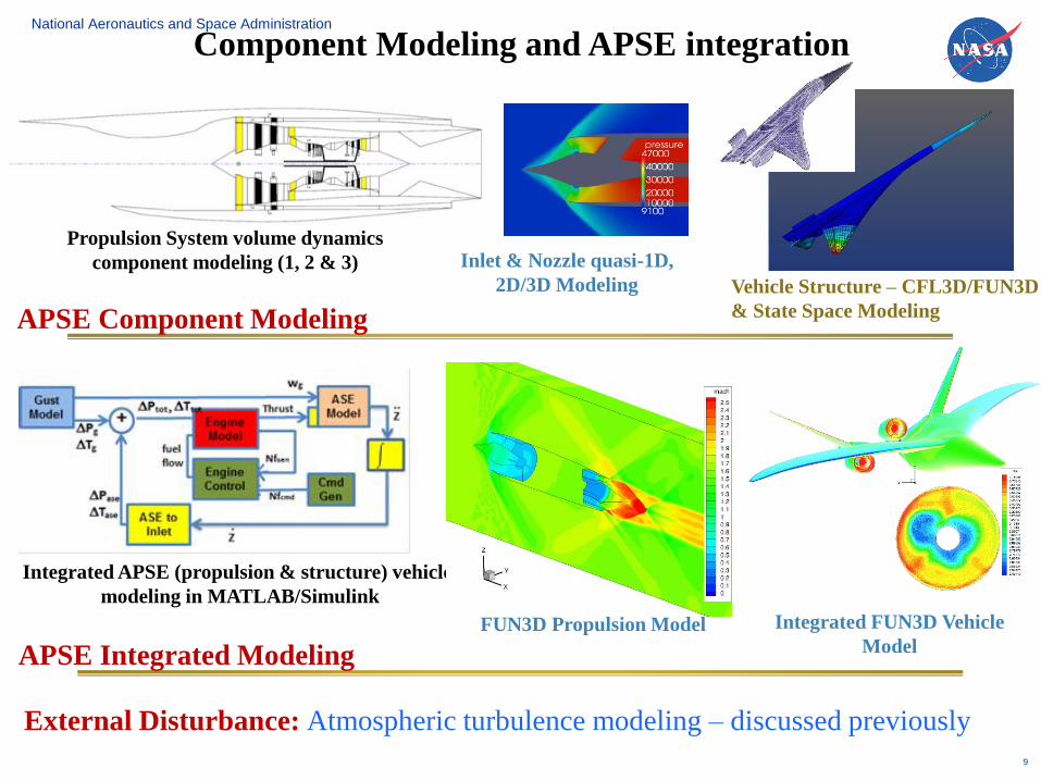
National Aeronautics and Space Administration
www.nasa.gov
Vehicle Structure – CFL3D/FUN3D
& State Space Modeling
9
Inlet & Nozzle quasi-1D,
2D/3D Modeling
Propulsion System volume dynamics
component modeling (1, 2 & 3)
Integrated APSE (propulsion & structure) vehicle
modeling in MATLAB/Simulink
FUN3D Propulsion Model Integrated FUN3D Vehicle
Model
APSE Component Modeling
APSE Integrated Modeling
External Disturbance: Atmospheric turbulence modeling – discussed previously
Component Modeling and APSE integration
National Aeronautics and Space Administration
www.nasa.gov 10
References1. Silva, W. A., et al. “The NASA High Speed ASE Project: Computational Analyses of a Low-Boom Supersonic
Configuration,” AIAA 2014-0675, AIAA SciTech Conference, Harbor Maryland, Jan. 13-17, 2014.
2 Kopasakis, G.; Connolly, J. W.; Seidel, J.; “Propulsion System Dynamic Modeling of the NASA Supersonic
Concept Vehicle for AeroPropulsoServoElasticity,” AIAA 2014-3684, AIAA Joint Propulsion Conference and
Exhibit, Cleveland Ohio, July 28-30, 2014.
3 Connolly, J. W.; Jan-Renee-Carlson; Kopasakis, G.; Woolwine, K.; “Nonlinear Dynamic Modeling of a
Supersonic Commercial Transport Turbo-Machinery Propulsion System for Aero-Propulso-Servo-
Elasticity Research” AIAA 2015-4031, AIAA 2015-4143, 51st AIAA Joint Propulsion Conference and
Exhibit, Orlando FL, July 27-29, 2015.
4 Kopasakis, G; Cheng, L.; Connolly, J. W; “Stage-by-Stage and Parallel Flow Path Compressor Modeling for a
Variable Cycle Engine” AIAA 2015-4143, 51st AIAA Joint Propulsion Conference and Exhibit, Orlando FL,
July 27-29, 2015
5 Connolly, J. W.; Friedlander, D.; Kopasakis, G; “Computational Fluid Dynamics Modeling of a Supersonic
Nozzle and Integration into a Variable Cycle Engine Model,” AIAA 2014-3687, AIAA Joint Propulsion
Conference, Cleveland, Ohio, July 28-30, 2014.
6 Kopasakis, G.; Connolly, J. W.; Kratz, J; “Quasi One-Dimensional Unsteady Modeling of External Compression
Supersonic Inlets” 48thst AIAA Joint Propulsion Conference and Exhibit, 2012
7 Kopasakis, G.; Connolly, J. W.; Paxson, D. E.; Ma, P.; “Volume Dynamics Propulsion System Modeling for
Supersonic Vehicle Research,” GT2008-50524, ASME TurboExpo 2008, Berlin Germany; NASA/TM-215172;
Journal of Turbomachinery, Vol. 132, October 2010.
8 Kopasakis, G; “Feedback Control Systems Loop Shaping Design With Practical Considerations,” NASA/TM—
2007-215007.
9 Kopasakis, G.; “Atmospheric Turbulence Modeling for Aero Vehicles: Fractional Order Fits,” NASA/TM—
2010-216961/REV1
10 Connolly, J. W; Kopasakis, G; “Loop Shaping Control Design for a Supersonic Propulsion System Model
Using QFT Specifications and Bounds” 46th AIAA Joint Propulsion Conference and Exhibit, 2010
Several other references that can be found within the references listed here