Embed Size (px)
Citation preview
DRILLING WITH CASING
TUBULAR TECHNOLOGY AND SERVICES
DWCTM
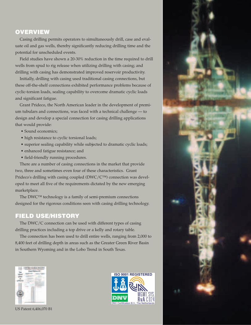
OVERVIEWCasing drilling permits operators to simultaneously drill, case and eval-
uate oil and gas wells, thereby significantly reducing drilling time and the
potential for unscheduled events.
Field studies have shown a 20-30% reduction in the time required to drill
wells from spud to rig release when utilizing drilling with casing; and
drilling with casing has demonstrated improved reservoir productivity.
Initially, drilling with casing used traditional casing connections, but
these off-the-shelf connections exhibited performance problems because of
cyclic-torsion loads, sealing capability to overcome dramatic cyclic loads
and significant fatigue.
Grant Prideco, the North American leader in the development of premi-
um tubulars and connections, was faced with a technical challenge — to
design and develop a special connection for casing drilling applications
that would provide:
• Sound economics;
• high resistance to cyclic torsional loads;
• superior sealing capability while subjected to dramatic cyclic loads;
• enhanced fatigue resistance; and
• field-friendly running procedures.
There are a number of casing connections in the market that provide
two, three and sometimes even four of these characteristics. Grant
Prideco's drilling with casing coupled (DWC/C™) connection was devel-
oped to meet all five of the requirements dictated by the new emerging
marketplace.
The DWC™ technology is a family of semi-premium connections
designed for the rigorous conditions seen with casing drilling technology.
FIELD USE/HISTORYThe DWC/C connection can be used with different types of casing
drilling practices including a top drive or a kelly and rotary table.
The connection has been used to drill entire wells, ranging from 2,000 to
8,400 feet of drilling depth in areas such as the Greater Green River Basin
in Southern Wyoming and in the Lobo Trend in South Texas.
US Patent 6,406,070 B1
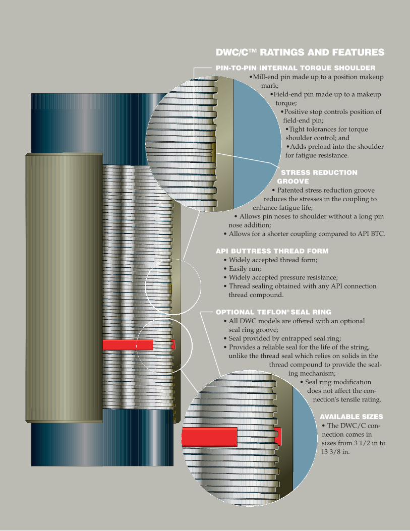
DWC/C™ RATINGS AND FEATURES
PIN-TO-PIN INTERNAL TORQUE SHOULDER•Mill-end pin made up to a position makeup
mark;•Field-end pin made up to a makeup
torque;•Positive stop controls position offield-end pin;•Tight tolerances for torqueshoulder control; and•Adds preload into the shoulderfor fatigue resistance.
STRESS REDUCTIONGROOVE
• Patented stress reduction groovereduces the stresses in the coupling to
enhance fatigue life;• Allows pin noses to shoulder without a long pin
nose addition;• Allows for a shorter coupling compared to API BTC.
API BUTTRESS THREAD FORM• Widely accepted thread form;• Easily run;• Widely accepted pressure resistance;• Thread sealing obtained with any API connection
thread compound.
OPTIONAL TEFLON® SEAL RING• All DWC models are offered with an optional
seal ring groove;• Seal provided by entrapped seal ring;• Provides a reliable seal for the life of the string,
unlike the thread seal which relies on solids in thethread compound to provide the seal-
ing mechanism;• Seal ring modification
does not affect the con-nection's tensile rating.
AVAILABLE SIZES• The DWC/C con-nection comes insizes from 3 1/2 in to13 3/8 in.
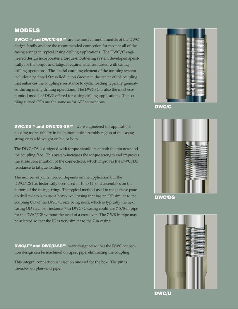
MODELS DWC/C™ and DWC/C-SR™ are the most common models of the DWC
design family and are the recommended connection for most or all of the
casing strings in typical casing drilling applications. The DWC/C engi-
neered design incorporates a torque-shouldering system developed specif-
ically for the torque and fatigue requirements associated with casing
drilling operations. The special coupling element of the torquing system
includes a patented Stress Reduction Groove in the center of the coupling
that enhances the coupling's resistance to cyclic loading typically generat-
ed during casing drilling operations. The DWC/C is also the most eco-
nomical model of DWC offered for casing drilling applications. The cou-
pling turned ODs are the same as for API connections.
DWC/DS™ and DWC/DS-SR™ were engineered for applications
needing more stability in the bottom hole assembly region of the casing
string or to add weight on bit, or both.
The DWC/DS is designed with torque shoulders at both the pin nose and
the coupling face. This system increases the torque strength and improves
the stress concentration of the connections, which improves the DWC/DS
resistance to fatigue loading.
The number of joints needed depends on the application but the
DWC/DS has historically been used in 10 to 12 joint assemblies on the
bottom of the casing string. The typical method used to make these psue-
do drill collars is to use a heavy wall casing that has an OD similar to the
coupling OD of the DWC/C size being used, which is typically the next
casing OD size. For instance, 7-in DWC/C casing could use 7 5/8-in pipe
for the DWC/DS without the need of a crossover. The 7 5/8-in pipe may
be selected so that the ID is very similar to the 7-in casing.
DWC/U™ and DWC/U-SR™ were designed so that the DWC connec-
tion design can be machined on upset pipe, eliminating the coupling.
This integral connection is upset on one end for the box. The pin is
threaded on plain-end pipe.
DWC/U
DWC/DS
DWC/C
MAKEUP PROCEDURES
MILL END
The mill end of DWC/C couplings is made to a position mark placed
on both the mill-end side of the coupling and the mill-end pin. This
precise makeup monitors not only the location of the coupling in the
axial direction, but also the rotational position of the coupling. This is
done to assure a very accurate mill-end pin position in order to obtain a
proper field-end makeup.
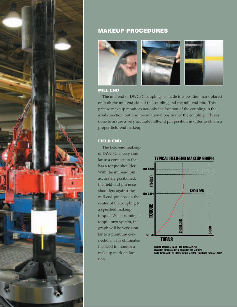
FIELD END
The field-end makeup
of DWC/C is very simi-
lar to a connection that
has a torque shoulder.
With the mill-end pin
accurately positioned,
the field-end pin nose
shoulders against the
mill-end pin nose in the
center of the coupling to
a specified makeup
torque. When running a
torque-turn system, the
graph will be very simi-
lar to a premium con-
nection. This eliminates
the need to monitor a
makeup mark on loca-
tion.
SHOULDER
TURNS
SHOU
LDER
TORQ
UE
Max 5200
Max 3314
Ref 20
5.00
0
Applied Torque = 5243 Top Turns = 2.738Shoulder Torque = 3314 Shoulder Tns = 2.629Delta Turns = 0.109 Delta Torque = 1929 Top Delta Rate = 17697
TYPICAL FIELD-END MAKEUP GRAPH(ft
-lbs)
TESTINGWith the introduction of fatigue requirements on a casing connection,
fatigue-life criteria had to be developed. An acceptable fatigue life at dif-
ferent stress levels was obtained to establish a target for testing. A stress
vs. number of cycles curve (S-N curve) was used to define the design win-
dow.
Once a design envelope was developed, the DWC design criteria was
validated by the use of Finite Element Analysis (FEA) and physical testing.
FINITE ELEMENT ANALYSIS (FEA)
Finite Element Analysis (FEA) was performed on
4 1/2 in-OD, 11.60 lb/ft, J-55 DWC/C to verify the
fatigue resistance of the connection.
The connection geometry was meshed to create the
computer model used in the FEA. Pure axial tension
was applied to the ends of the model for mean stress
and ramped up in steps to the final load. The maxi-
mum principle stresses for the nodes in the thread root
radii and the maximum stress points were used to
determine the stress concentration factor (SCF).
The SCF was calculated for every nodal point along
every pin and box root radius for each load step. The
maximum SCF was found in the pin imperfect thread
area, where a fatigue failure would be expected.
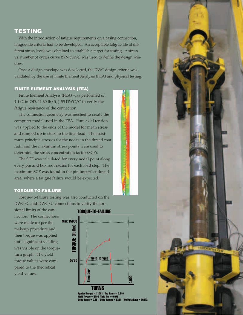
TORQUE-TO-FAILURE
Torque-to-failure testing was also conducted on the
DWC/C and DWC/U connections to verify the tor-
sional limits of the con-
nection. The connections
were made up per the
makeup procedure and
then torque was applied
until significant yielding
was visible on the torque-
turn graph. The yield
torque values were com-
pared to the theoretical
yield values.
Shou
lder
Max 15000
5790 Yield Torque
0.50
0
Applied Torque = 11081 Top Turns = 0.340Yield Torque = 5790 Yield Tns = 0.079Delta Turns = 0.261 Delta Torque = 5291 Top Delta Rate = 20272
TORQUE-TO-FAILURE
TORQ
UE
TURNS
(ft-lb
s)
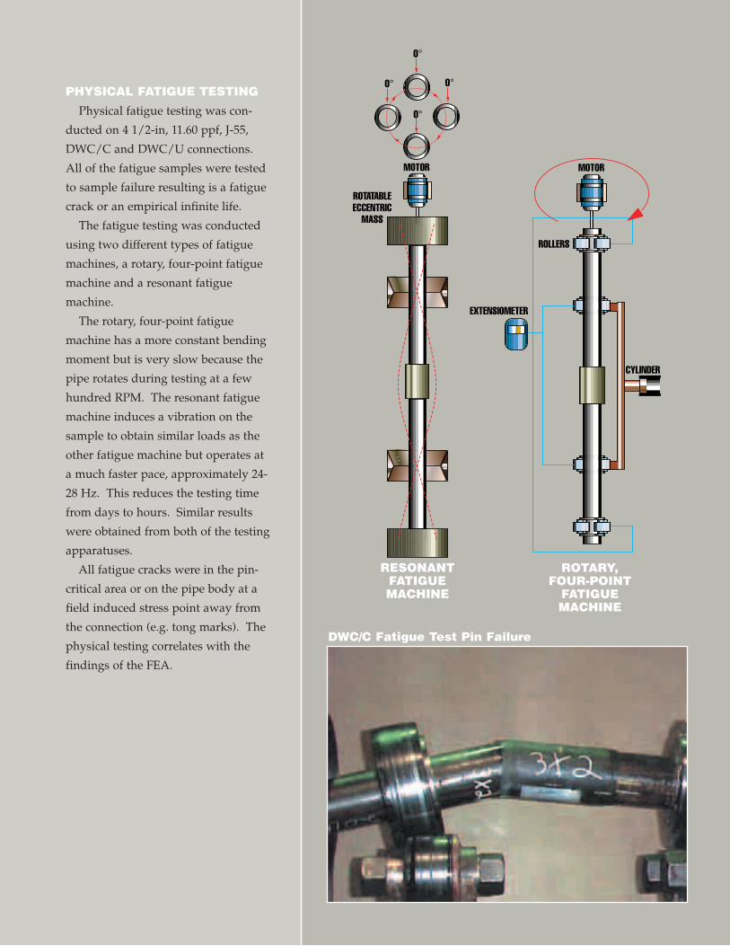
PHYSICAL FATIGUE TESTING
Physical fatigue testing was con-
ducted on 4 1/2-in, 11.60 ppf, J-55,
DWC/C and DWC/U connections.
All of the fatigue samples were tested
to sample failure resulting is a fatigue
crack or an empirical infinite life.
The fatigue testing was conducted
using two different types of fatigue
machines, a rotary, four-point fatigue
machine and a resonant fatigue
machine.
The rotary, four-point fatigue
machine has a more constant bending
moment but is very slow because the
pipe rotates during testing at a few
hundred RPM. The resonant fatigue
machine induces a vibration on the
sample to obtain similar loads as the
other fatigue machine but operates at
a much faster pace, approximately 24-
28 Hz. This reduces the testing time
from days to hours. Similar results
were obtained from both of the testing
apparatuses.
All fatigue cracks were in the pin-
critical area or on the pipe body at a
field induced stress point away from
the connection (e.g. tong marks). The
physical testing correlates with the
findings of the FEA.
DWC/C Fatigue Test Pin Failure
MOTOR MOTOR
ROLLERS
CYLINDER
EXTENSIOMETER
0°
0°
0°
0°
ROTATABLEECCENTRIC
MASS
ROTARY,FOUR-POINT
FATIGUEMACHINE
RESONANTFATIGUEMACHINE
www.grantprideco.com/dwc
TUBULAR TECHNOLOGY AND SERVICES
CORPORATE OFFICE
Grant Prideco, Inc.1330 Post Oak Blvd., Suite 2700Houston, Texas 77056 USA832.681.8000
Tubular Technology and Services1450 Lake Robbins Drive, Suite 500 The Woodlands, Texas 77380 USA281.297.8625 Fax: 281.297.8925
DWCTM
Grant Prideco has produced this brochure for general information only and it is not intended for design purposes.Although every effort has been made to maintain the accuracy and reliability of its contents, Grant Prideco in noway assumes responsibility of liability for any loss, damage or injury resulting from the use of information and dataherein. All applications for the material described are at the user's risk and are the user's responsibility.
Grant Prideco is a registered trademark of Grant Prideco, L.P.
DWC, DWC/C, DWC/C-SR, DWC/DS, DWC/DS-SR, DWC/U and DWC/U-SR are trademarks of GrantPrideco, L.P.
TEFLON is a registered trademark of DuPont de Nemours and Company, Inc.
© 2003 Grant Prideco. All rights reserved.TTS-DWC-10.03-5M-FMC