Embed Size (px)
Citation preview
DUSTER
Operation, Service& Parts Manual
For Models:S530 & S530N
FORM: S530book
May 2006 Rev. 11-09
TABLE OF CONTENTS
Introduction/Duster Installation .....................................................1
Operating Instructions .......................................................................2
Lubrication & Cleaning ......................................................................3
Safety Tips ............................................................................................4
Safety Decals ....................................................................................5-6
Diagram of Duster .............................................................................7
Troubleshooting ..................................................................................8 Frame & Fan Assembly................................................................9-10
Gearbox Assembly ......................................................................11-12
Hopper & Control Assembly ....................................................13-14
Narrow Row Distributor ................................................................ 15
Wide Row Distributor ..................................................................... 16
Row Crop Boom .........................................................................17-18
Driveline ............................................................................................ 19
Clutch Assembly .............................................................................. 20
Limited Warranty ............................................................................. 21
MODEL #: _________________________________________________
DATE OF PURCHASE: _______________________________________
SERIAL NUMBER: ___________________________________________

INTRODUCTION
We welcome you as an owner of a Gearmore duster. Please read the following instructions and refer to them when required.
APPLICATION RATES: Adjustable from 12 to 80 pounds per acre.
HOPPER: The tank is thick walled polyethylene. (See Note)
BLOWER: Dynamically balanced steel fan in an aluminum housing.
DISTRIBUTORS: Two completely adjustable 360º nozzles.
DUSTER INSTALLATION
The Duster should be mounted on a fl at surface, always clear away all people not involved in the opera-tion, including children and animals.
1. With tractor engine off and key out of the ignition, hook the tractors lower lift arms to the duster lower lift pins. (S530 comes with Cat. 1 - 2 pin as standard equipment.)
2. Remove tractor top link and install on duster.
3. Mount other side of top link back on the tractor.
4. P.T.O. Installation:
First, connect the P.T.O. shaft to the tractor. With the shaft in its shortest position, there should be about a 2” clearance between the end of the gearbox shaft and the end of the P.T.O. shaft. Should it be necessary to shorten the P.T.O. shaft, shorten both male and female shafts equally, keeping the protective tube covers 1” shorter than the steel tubes.
Particular attention should be given to carefully removing all burrs and to clean and lubricate the steel tubes and protective covers. There must be suffi cient telescopic movement so that the two tubes do not touch the end of the P.T.O. shaft.
It is most important to carefully raise and lower the duster with the tractor hydraulic system, making sure that the P.T.O. shaft does not bottom or disengage the telescopic shaft tubes, otherwise damage may occur.
NOTE: Driveshaft angle should not exceed 15º when in operation. 1

1. Inspect for damage and loose or missing parts. Make sure all fi ttings and drive components are secure.
2. Lubrication: See Lubrication Section. 3. Check hopper for any foreign objects.
1. Calculate the exact amount of sulfur needed for the treatment.
2. Carefully read the instructions for the manufacturer’s use of the sulfur, check the conditions for use, the correct dosage and the expiration date.
3. Push fl ow adjusting lever away from the tractor, which is the closed position. 4. Fill hopper with material being used. (Note: Sulfur Powder Only)
5. Due to the inconsistency of sulfur, it is almost impossible to set a true rate chart. For this reason, Gearmore can only recommend an average start rate at 1 1/2 on control lever for 15 lbs. of sulfur per acre at 4 M.P.H. Adjust lever up or down from there.
6. Start engine and engage tractor P.T.O. at engine idle.
7. Pull lever toward the tractor, which increases the powder fl ow.
8. After locating the delivery position that meets your required application rate, disengage P.T.O. and turn tractor engine off. Set the adjustable gray handle so the operator can easily return to that position.
9. Restart engine and engage P.T.O., gradually increase engine R.P.M. and start dusting.
NOTE: Small gray plastic handle is only a “stop set”, thus little locking pressure is required.
BEFORE OPERATING YOUR DUSTER
2
TO OPERATE DUSTER
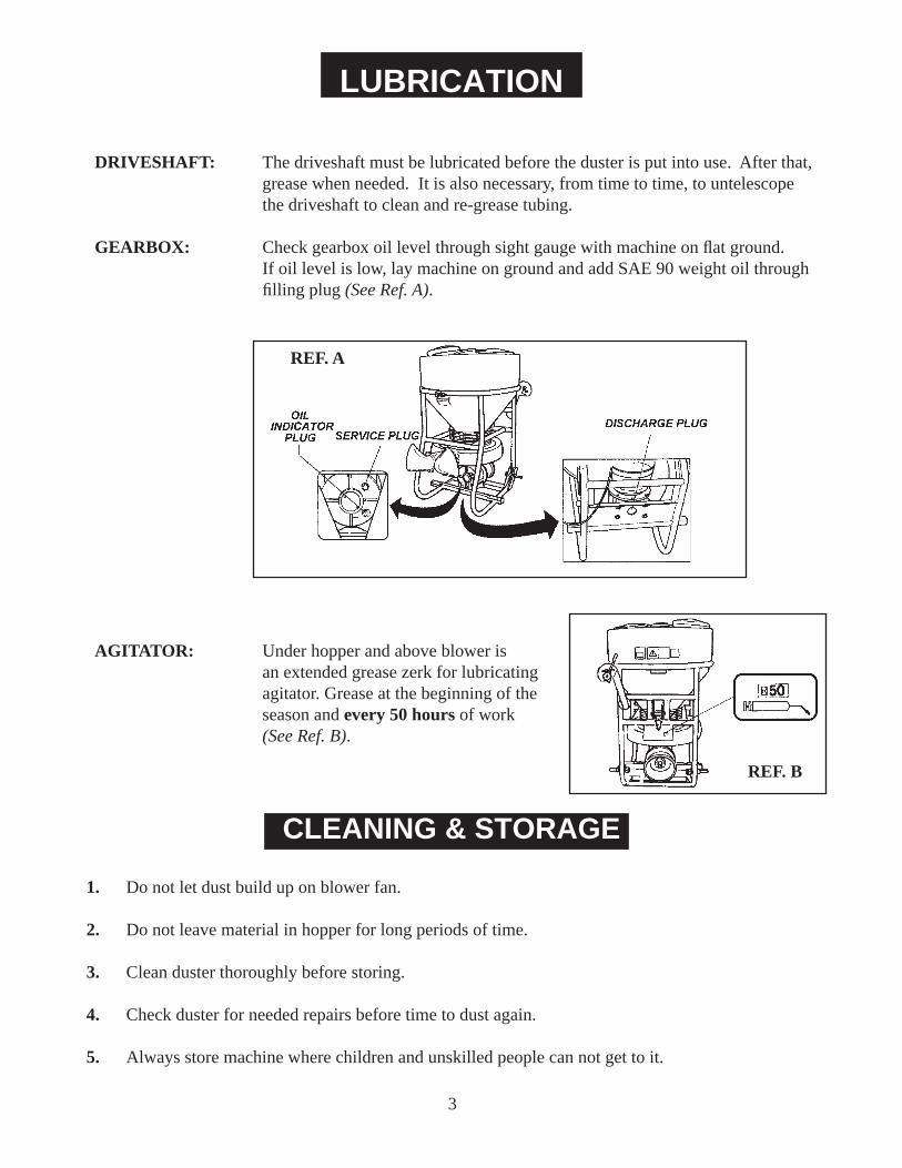
DRIVESHAFT: The driveshaft must be lubricated before the duster is put into use. After that, grease when needed. It is also necessary, from time to time, to untelescope the driveshaft to clean and re-grease tubing.
GEARBOX: Check gearbox oil level through sight gauge with machine on fl at ground. If oil level is low, lay machine on ground and add SAE 90 weight oil through fi lling plug (See Ref. A).
AGITATOR: Under hopper and above blower is an extended grease zerk for lubricating agitator. Grease at the beginning of the season and every 50 hours of work (See Ref. B).
LUBRICATION
1. Do not let dust build up on blower fan.
2. Do not leave material in hopper for long periods of time.
3. Clean duster thoroughly before storing.
4. Check duster for needed repairs before time to dust again.
5. Always store machine where children and unskilled people can not get to it.
CLEANING & STORAGE
REF. B
REF. A
3
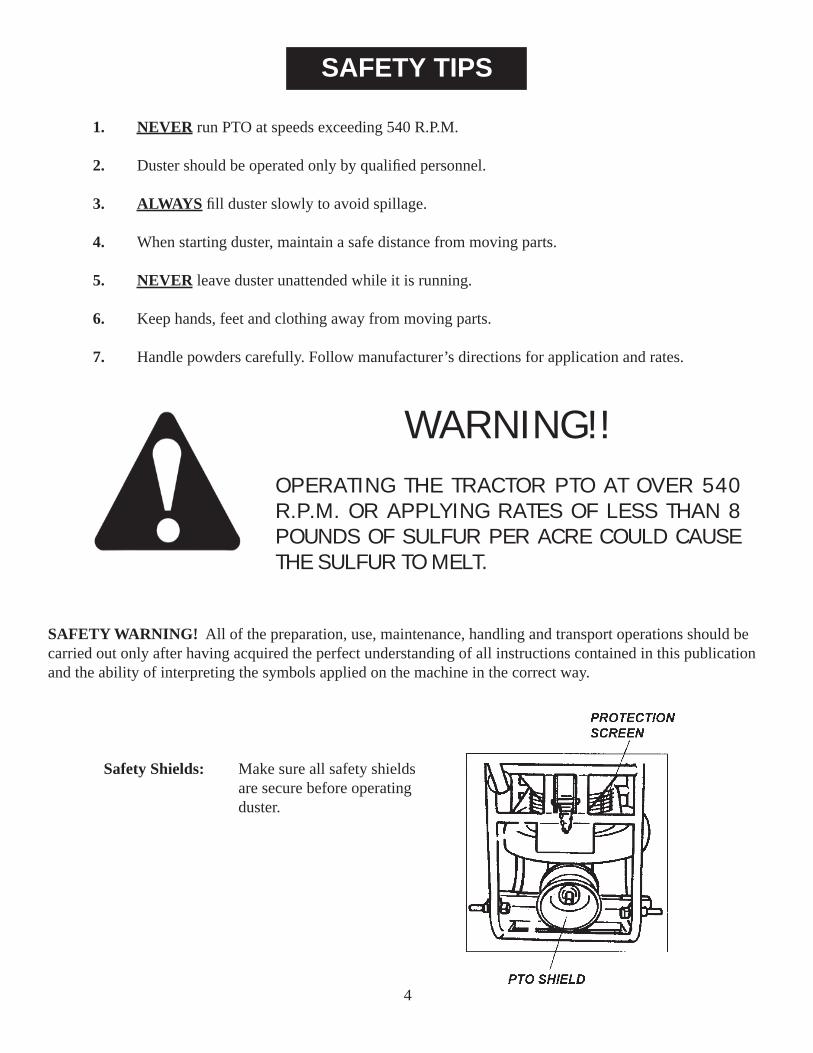
SAFETY TIPS
1. NEVER run PTO at speeds exceeding 540 R.P.M.
2. Duster should be operated only by qualifi ed personnel.
3. ALWAYS fi ll duster slowly to avoid spillage.
4. When starting duster, maintain a safe distance from moving parts.
5. NEVER leave duster unattended while it is running.
6. Keep hands, feet and clothing away from moving parts.
7. Handle powders carefully. Follow manufacturer’s directions for application and rates.
Safety Shields: Make sure all safety shields are secure before operating duster.
SAFETY WARNING! All of the preparation, use, maintenance, handling and transport operations should be carried out only after having acquired the perfect understanding of all instructions contained in this publication and the ability of interpreting the symbols applied on the machine in the correct way.
WARNING!!OPERATING THE TRACTOR PTO AT OVER 540 R.P.M. OR APPLYING RATES OF LESS THAN 8 POUNDS OF SULFUR PER ACRE COULD CAUSE THE SULFUR TO MELT.
4
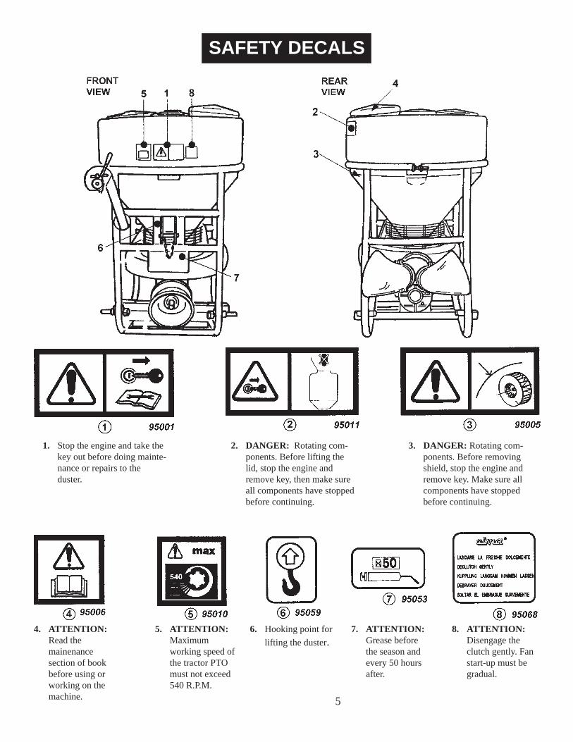
SAFETY DECALS
4. ATTENTION: Read the mainenance section of book before using or working on the machine.
5. ATTENTION: Maximum working speed of the tractor PTO must not exceed 540 R.P.M.
6. Hooking point for lifting the duster.
7. ATTENTION: Grease before the season and every 50 hours after.
8. ATTENTION: Disengage the clutch gently. Fan start-up must be gradual.
3. DANGER: Rotating com- ponents. Before removing shield, stop the engine and remove key. Make sure all components have stopped before continuing.
1. Stop the engine and take the key out before doing mainte- nance or repairs to the duster.
2. DANGER: Rotating com- ponents. Before lifting the lid, stop the engine and remove key, then make sure all components have stopped before continuing.
5

SAFETY Continued
A. Polyethylene or polyvinyl gloves.
B. Complete overalls, in waterproof cotton, to guarantee transpiration, with side polypropylene coating. It is IMPORTANT to fi nd disposable overalls with these materials so that after use they are disposed of in the same way as the toxic waste.
C. Half-size masks in neoprene rubber with one or two fi lters. It is IMPOR- TANT to use fi lters designed for gas or organic vapors combined with fi lters against powder for mists and irritating powders or for mists of harmful or toxic powders.
PERSONAL SAFETY WEAR:
The toxicity of phytopharmeceuticals compels the people using them to wear adequately protective clothing and accessories to avoid the risks of contamination by contact or inhaling the sulfur.
THE OPERATORS MUST WEAR:
LIFTING DUSTER Remove the head before lifting the duster.
All operations should be carried out with the tank completely empty.
1. Check that the cables or the chains are suffi cient enough for the weight to be lifted.
2. Hook the machine in the supporting point indicated on the frame by the decal and check the tightening of all of the parts involved in the operation.
3. Lift the machine, placing it on the means of transport, which must be perfectly stable.
4. During the transport, the machine should be tied and fastened to the means of transport by an appropriate harness.
6
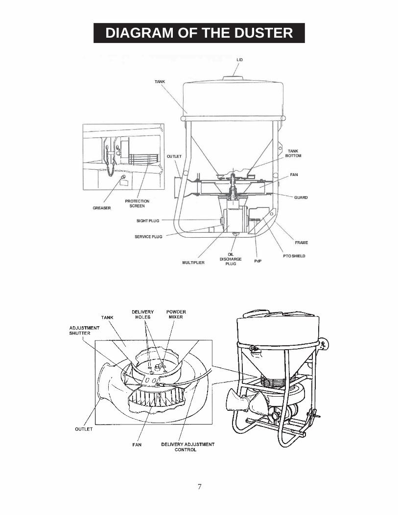
DIAGRAM OF THE DUSTER
7

TROUBLESHOOTING CHART
8
PROBLEM CAUSE SOLUTION
Oil leakage The input shaft seal is defective Replace input shaft seal
The gasket on the gearbox cover is defective
Replace gearbox cover gasket
Vibration in fan The fan is caked with sulfur Clean sulfur build-up off
The fan is out of balance Check fan blades, if damaged or broken, replace fan
Continuous noise Bearings in gearbox dry or damaged
Check bearings in gearbox, if bad or damaged, replace
Sulfur not being delivered
The feeding holes on the tank bottom are clogged
Clean the bottom feeding holes
Bottom of tank caked with sulfur Clean caked sulfur off the tank bot-tom
Sulfur delivery not uniform
Nozzles caked with sulfur Clean caked sulfur off nozzles
Nozzle end damaged or bent Open damaged or bent nozzle back up
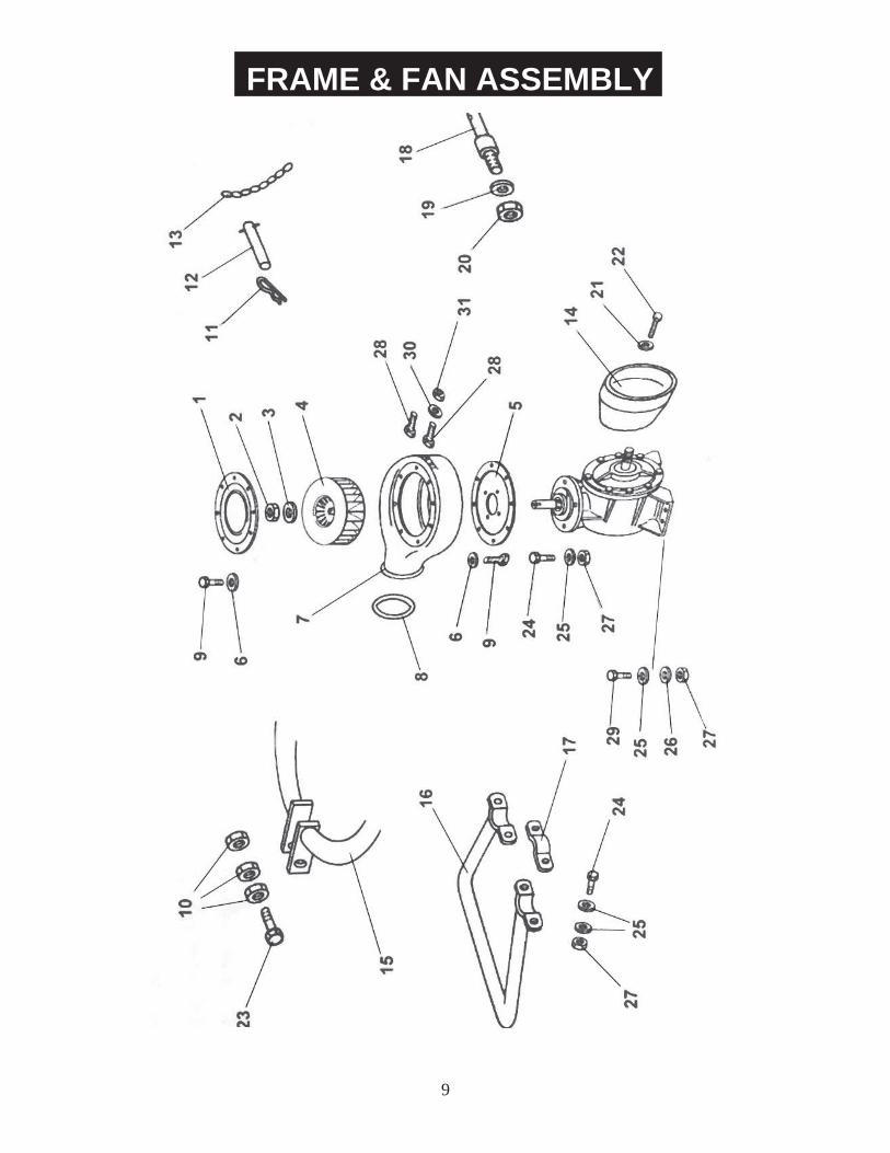
FRAME & FAN ASSEMBLY
9

REF # QTY. PART NO. DESCRIPTION
1 1 S0.495.000 Fan Cover 2 2 DA.024.0BF Nut M24 3 2 RP.024.000 Washer D.24 4 2 S0.437.100 Fan D.500 5 1 S0.494.000 Mounting Plate 6 16 RP008000 Washer D.8 7 1 S0.436.000 Blower Body 8 1 OR.004.700 O-Ring D.177.39 x 3.53 9 16 TE.008.016T Bolt M8 x 16 10 3 D0.12.5587G Nut M12 11 1 00.100.004 Hair Pin 12 1 04.076.000 Pin, Top Link 13 1 02.278.040 Chain D.2.2 L=400 14 1 02.442.000 Shield, PTO 15 1 S0.477.000 Main Frame 16 1 S0.483.000 Rear Bumper 17 2 S0.493.000 Clamp 18 2 S0.479.000 Pin, Lift Cat. 1 & 2 19 2 RP.027.000 Washer D.27 20 2 D0.27.5588G Nut M27 21 3 RP.006.000 Washer D.6 22 3 TE.006.020T Bolt M6 x 20 23 1 TE.012.090T Bolt M12 x 90 24 8 TE.010.035T Bolt M10 x 35 25 16 RP.010.000 Washer D.10 26 4 RP.010.030 Washer D.10 x 30 27 12 D0.10.5588G Nut M10 28 2 TE.012.030T Bolt M12 x 30 29 4 TE.010.030T Bolt M10 x 30 30 2 RP.012.000 Washer D.12 31 2 D0.12.5588G Nut M12
FRAME & FAN ASSEMBLY
10
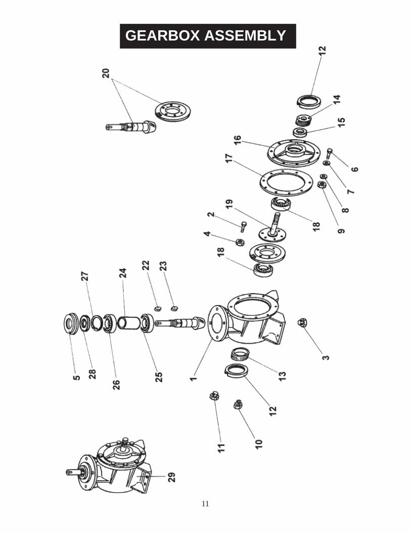
GEARBOX ASSEMBLY
11
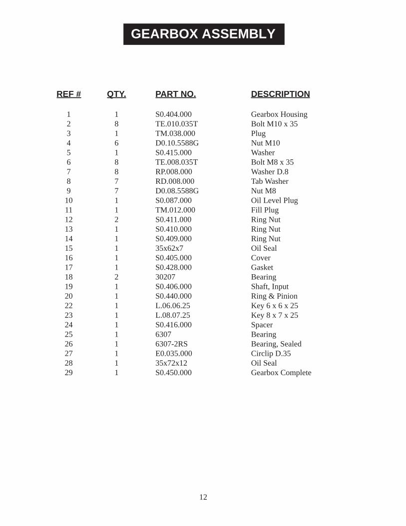
REF # QTY. PART NO. DESCRIPTION
1 1 S0.404.000 Gearbox Housing 2 8 TE.010.035T Bolt M10 x 35 3 1 TM.038.000 Plug 4 6 D0.10.5588G Nut M10 5 1 S0.415.000 Washer 6 8 TE.008.035T Bolt M8 x 35 7 8 RP.008.000 Washer D.8 8 7 RD.008.000 Tab Washer 9 7 D0.08.5588G Nut M8 10 1 S0.087.000 Oil Level Plug 11 1 TM.012.000 Fill Plug 12 2 S0.411.000 Ring Nut 13 1 S0.410.000 Ring Nut 14 1 S0.409.000 Ring Nut 15 1 35x62x7 Oil Seal 16 1 S0.405.000 Cover 17 1 S0.428.000 Gasket 18 2 30207 Bearing 19 1 S0.406.000 Shaft, Input 20 1 S0.440.000 Ring & Pinion 22 1 L.06.06.25 Key 6 x 6 x 25 23 1 L.08.07.25 Key 8 x 7 x 25 24 1 S0.416.000 Spacer 25 1 6307 Bearing 26 1 6307-2RS Bearing, Sealed 27 1 E0.035.000 Circlip D.35 28 1 35x72x12 Oil Seal 29 1 S0.450.000 Gearbox Complete
GEARBOX ASSEMBLY
12

HOPPER & CONTROL ASSEMBLY
13

HOPPER & CONTROL ASSEMBLY
REF # QTY. PART NO. DESCRIPTION
1 1 S0.497.100C Hopper Assembly 2 1 S0.497.100 Hopper Only 3 1 02.405.100 Lid Assembly 4 1 S0.214.100 Handle Assembly 5 1 02.738.040 Extension M10 x 1 L=400 6 7 D0.08.5588G Nut M8 7 1 RP.010.000 Washer D.10 8 1 S0.243.000 Bushing 9 1 S0.517.000 Bracket 10 2 S0.212.000 Swivel 11 4 DA.006.0AG Nut M6 12 1 IS.010.001 Grease Zerk M10 x 1 13 1 02.737.000 Adapter M10 14 2 S0.488.000 Wire Screen 15 1 TE.008.025T Bolt M8 x 25 16 10 RP.008.024 Washer D.8 x 24 17 1 S0.076.000 Agitator 18 1 S0.492.000 Gasket 19 1 S0.475.000 Support, Hopper 20 1 S0.476.000 Metering Plate 21 1 S0.480.000 Spring 22 1 S0.239.000 Felt Strip 23 1 S0.219.010 Bushing, Agitator 24 2 S0.083.000 Bolt M8 x 42 25 2 S0.211.000 Spring D.2.3 L=22 26 2 RP.008.000 Washer D.8 27 3 DA.008.0AG Nut M8 28 1 02.496.000 Carriage Bolt M8 x 20 29 4 RP.010.000 Washer D.10 x 30 30 1 S0.214.001 Control Handle 31 1 S0.502.000 Support Bracket Handle 32 4 TE.008.025T Bolt M8 x 25 33 4 S0.489.000 Support Bracket 34 4 RP.006.024 Washer D.6 x 24 35 4 TE.006.020T Bolt M6 x 20 36 1 S0.214.004 Inner Handle Bracket 37 1 S0.216.000 Locking Handle 38 1 TE.010.050T Bolt M10 x 50 39 1 S0.215.000 Grip 40 1 S0.518.000 Threaded Rod 41 2 TE.010.090T Bolt M10 x 90 42 5 D0.10.5588G Nut M10 43 1 S0.508.000 Bushing 44 2 RP.010.030 Washer D.10 x 30 45 2 S0.511.000 Support Bracket 14
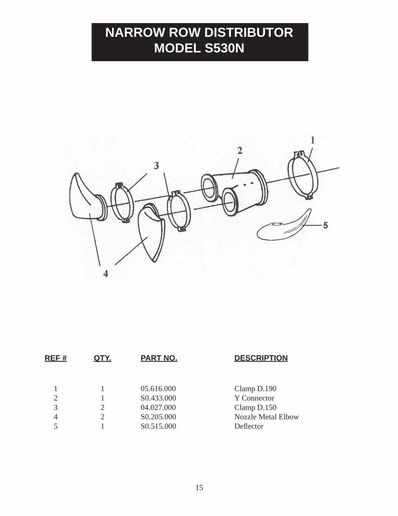
NARROW ROW DISTRIBUTORMODEL S530N
1 1 05.616.000 Clamp D.190 2 1 S0.433.000 Y Connector 3 2 04.027.000 Clamp D.150 4 2 S0.205.000 Nozzle Metal Elbow 5 1 S0.515.000 Defl ector
REF # QTY. PART NO. DESCRIPTION
15
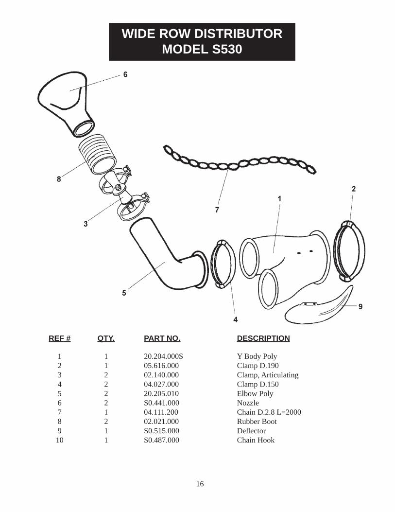
WIDE ROW DISTRIBUTORMODEL S530
1 1 20.204.000S Y Body Poly 2 1 05.616.000 Clamp D.190 3 2 02.140.000 Clamp, Articulating 4 2 04.027.000 Clamp D.150 5 2 20.205.010 Elbow Poly 6 2 S0.441.000 Nozzle 7 1 04.111.200 Chain D.2.8 L=2000 8 2 02.021.000 Rubber Boot 9 1 S0.515.000 Defl ector 10 1 S0.487.000 Chain Hook
REF # QTY. PART NO. DESCRIPTION
16
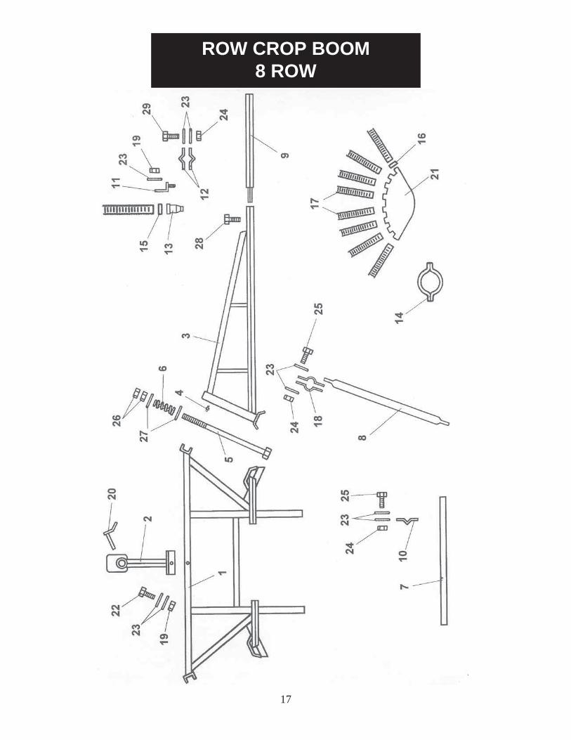
ROW CROP BOOM8 ROW
17
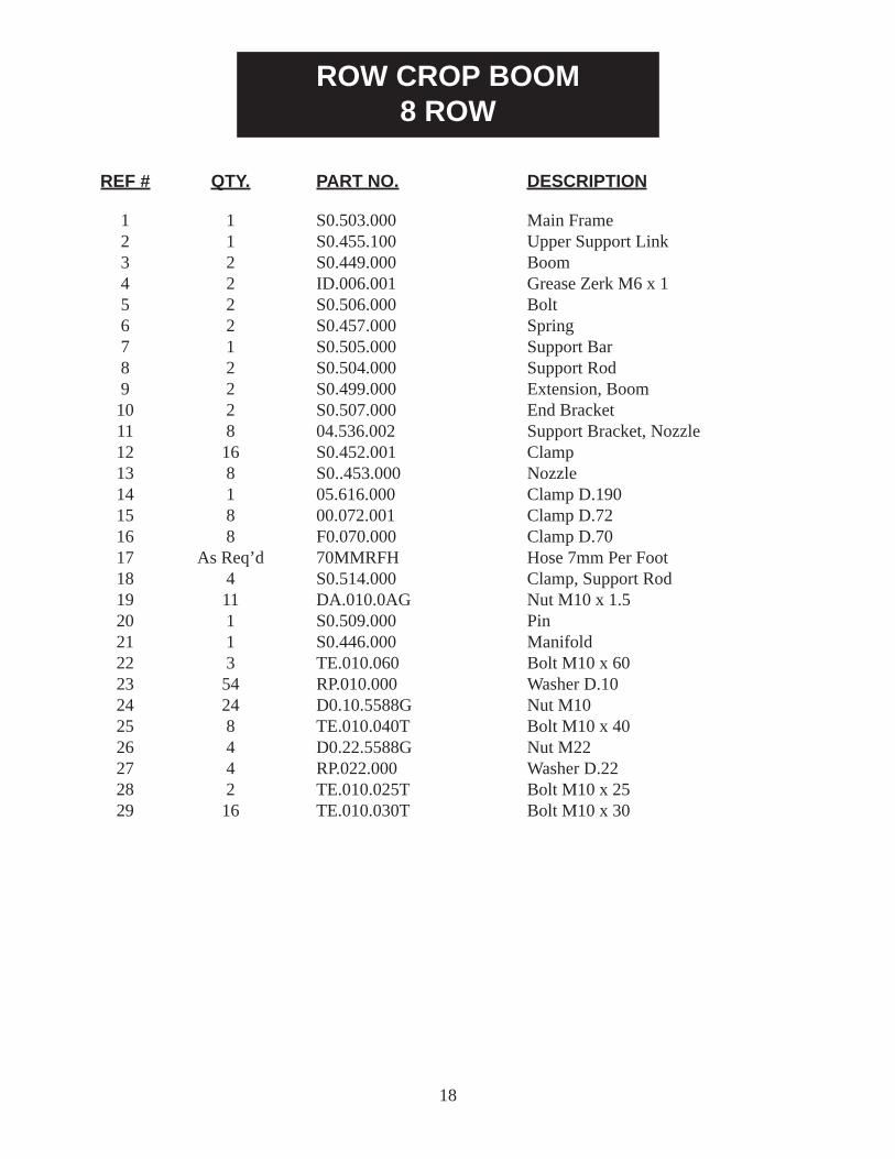
ROW CROP BOOM8 ROW
REF # QTY. PART NO. DESCRIPTION
1 1 S0.503.000 Main Frame 2 1 S0.455.100 Upper Support Link 3 2 S0.449.000 Boom 4 2 ID.006.001 Grease Zerk M6 x 1 5 2 S0.506.000 Bolt 6 2 S0.457.000 Spring 7 1 S0.505.000 Support Bar 8 2 S0.504.000 Support Rod 9 2 S0.499.000 Extension, Boom 10 2 S0.507.000 End Bracket 11 8 04.536.002 Support Bracket, Nozzle 12 16 S0.452.001 Clamp 13 8 S0..453.000 Nozzle 14 1 05.616.000 Clamp D.190 15 8 00.072.001 Clamp D.72 16 8 F0.070.000 Clamp D.70 17 As Req’d 70MMRFH Hose 7mm Per Foot 18 4 S0.514.000 Clamp, Support Rod 19 11 DA.010.0AG Nut M10 x 1.5 20 1 S0.509.000 Pin 21 1 S0.446.000 Manifold 22 3 TE.010.060 Bolt M10 x 60 23 54 RP.010.000 Washer D.10 24 24 D0.10.5588G Nut M10 25 8 TE.010.040T Bolt M10 x 40 26 4 D0.22.5588G Nut M22 27 4 RP.022.000 Washer D.22 28 2 TE.010.025T Bolt M10 x 25 29 16 TE.010.030T Bolt M10 x 30
18
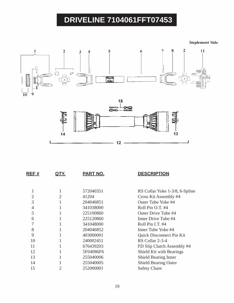
DRIVELINE 7104061FFT07453
REF # QTY. PART NO. DESCRIPTION
1 1 572040351 RS Collar Yoke 1-3/8, 6-Spline 2 2 41204 Cross Kit Assembly #4 3 1 204046851 Outer Tube Yoke #4 4 1 341038000 Roll Pin O.T. #4 5 1 225100860 Outer Drive Tube #4 6 1 225120860 Inner Drive Tube #4 7 1 341048000 Roll Pin I.T. #4 8 1 204046852 Inner Tube Yoke #4 9 1 403000001 Quick Disconnect Pin Kit 10 1 240002451 RS Collar 2-3-4 11 1 676439203 FD Slip Clutch Assembly #4 12 1 5F04086F6 Shield Kit with Bearings 13 1 255040006 Shield Bearing Inner 14 1 255040005 Shield Bearing Outer 15 2 252000001 Safety Chain
19

FD2 CLUTCH ASSEMBLY #4676439203
REF # QTY. PART NO. DESCRIPTION
1 8 303001400 Bolt 4 1 253046201 Flange Yoke 5 2 247006201 Friction Disc 6 1 513620301 Flange Hub 7 1 403000009 Pin Kit 8 1 248620001 Pressure Plate 9 1 367003620 Belleville Spring 9 1 367005620 Belleville Spring 10 1 246000018 Compression Spring 11 1 264620001 Clutch Housing
20
GEARMORE, INC., warrants each new Gearmore product to be free from defects in material and workmanship for a period of twelve (12) months from date of purchase to the original purchaser. This warranty shall not apply to implements or parts that have been subject to misuse, negligence, accident, or that have been altered in any way.
Our obligation shall be limited to repairing or replacement of any part, provided that such part is returned within thirty (30) days from date of failure to Gearmore through the dealer from whom the purchase was made, transportation charges prepaid.
This warranty shall not be interpreted to render us liable for injury or damages of any kind or nature, direct, consequential or contingent, to person or property. This warranty does not extend to loss of crops, loss because of delay in harvesting or any other expenses, for any other reasons.
Gearmore in no way warranties engines, tires, or other trade accessories, since these items are warranted separately by these respective manufacturers.
Gearmore reserves the right to make improvements in design or changes in specifi cation at any time, without incurring any obligations to owners or units previously sold.
GEARMORE, INC.13477 Benson Ave.
Chino, CA 91710Always refer to and heed machine operating warning decals on machine.
The serial number of this product is stored in our computer database, thus submitting a warranty registration card is not required.
21
LIMITED WARRANTY


![Dacia Duster[1]](https://img.pdfslide.us/doc/110x75/55cf9d19550346d033ac3fee/dacia-duster1.jpg)