Embed Size (px)
Citation preview

INSTRUCTION MANUAL
DFB10/RAD10
1
INSTRUCTION MANUAL
DulcoFlex Peristaltic Pumps: DFB10/RAD10
This manual forms an integral part of the pump and must accompany it until its demolition. The peristaltic pump is a machine destined to work in industrial areas and as such the instruction manual must form part of the legislative dispositions and the applicable technical standards and does not substitute any installation standard or eventual additional standard.
The person in charge of safety should therefore guarantee that
- The pump is transported, installed, put in service, used, maintained and repaired by qualified personnelwho should therefore posses:
- Specific training and sufficient experience.
- Knowledge of the technical standards and applicable laws.
- Knowledge of the general national and local safety standards and also of installation.
Any work carried out on the electrical part of the pump should be authorized by the person responsible for safety. Given that the pump is destined to form part of an installation, it is the responsibility of whoever supervises the installation to guarantee absolute safety, adopting the necessary measures of additional protection.
GENERAL SAFETY WARNING
Pumps are machines that due to their functioning under pressure and moving parts can present dangers.
- Improper use- Removing the protections and/or disconnecting the protection device- The lack of inspections and maintenance
CAN CAUSE SERIOUS DAMAGE OR INJURY
P/N 1092491
INSTRUCTION MANUAL
2
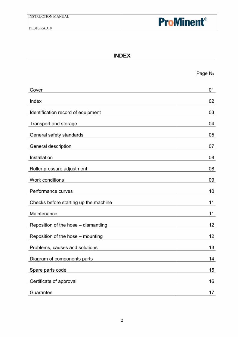
INDEX
Page N#
Cover 01
Index 02
Identification record of equipment 03
Transport and storage 04
General safety standards 05
General description 07
Installation 08
Roller pressure adjustment 08
Work conditions 09
Performance curves 10
Checks before starting up the machine 11
Maintenance 11
Reposition of the hose – dismantling 12
Reposition of the hose – mounting 12
Problems, causes and solutions 13
Diagram of components parts 14
Spare parts code 15
Certificate of approval 16
Guarantee 17
DFB10/RAD10

INSTRUCTION MANUAL
3
IDENTIFICATION RECORD OF EQUIPMENT
MANUFACTURER:
MODEL OF PUMP: DFB10/RAD10SERIAL NUMBER:
DRIVER MARK: DRIVER POWER / SPEED: REDUCER MAKE & MODEL:
REDUCTION RATIO:
FIXED SPEED MOTOR GEAR REDUCER: GEAR REDUCER WITH VFD:
WORK SPEED: MAXIMUM SPEED: MINIMUM SPEED:
WORKING MANOMETRIC PRESSURE: Maximum MAXIMUM DESIGN PRESSURE: 116 psi
HOSE MATERIAL: CONNECTIONS MATERIAL:
IMPORTER / SUPPLIER:
DFB10/RAD10

INSTRUCTION MANUAL
4
TRANSPORT and STORAGE
TRANSPORT
The pump is protected by a cardboard packaging.
The packaging materials are recyclable.
During transportation, the pump is in a resting position (the hose is not compressed)
STORAGE
The pump should be in a resting position. (The hose should not be compressed).
Avoid areas open to inclement weather or excessive humidity.
For storage periods of longer than 60 days, protect the coupling surfaces withadequate anti-oxidant products, remove hose/tube or remove one roller and rotateremaining roller out of contact with hose/tube.
Hose/tube spares should be stored in a dry place away from direct light.
DFB10/RAD10

INSTRUCTION MANUAL
5
GENERAL SAFETY STANDARDS
The instructions of this manual, whose inobservance isdetermined as a failure to meet safety standards, areidentified by this symbol
The instructions of this manual, whose inobservancecompromises electrical safety.
The instructions of this manual, whose inobservancecompromises the correct working of the pump, are identifiedwith this symbol.
Do not start the pump without first having installed the front cover.
For any manipulation of the equipment, it is necessary to make certain that the pump is stopped and the electricity supply disconnected.
Changing the hose should be done with the pump stopped.
Do not exceed the nominal pressure, speed or temperature of the pump, or use the pump for applications other than that originally planned without first consulting the manufacturer.
WARNING!
WARNING!
DFB10/RAD10
INSTRUCTION MANUAL
6
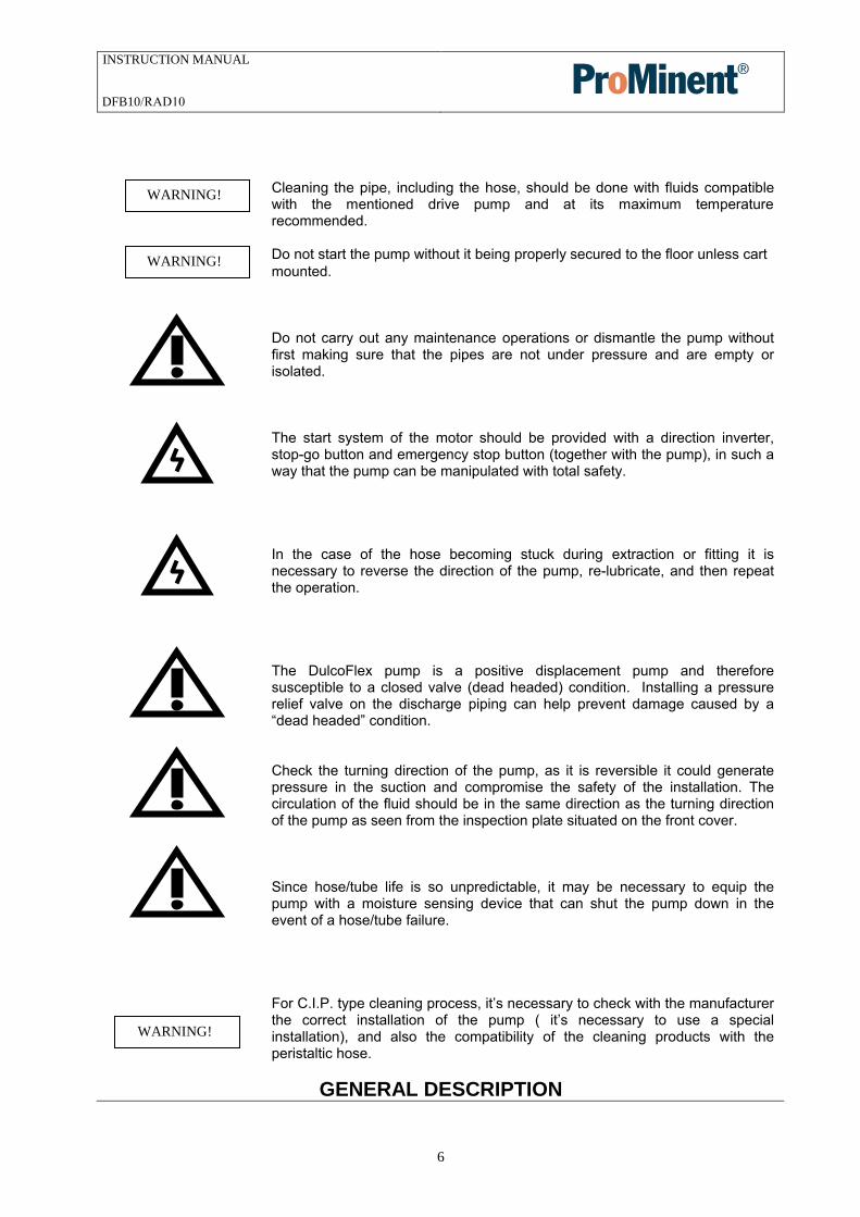
Cleaning the pipe, including the hose, should be done with fluids compatible with the mentioned drive pump and at its maximum temperature recommended.
Do not start the pump without it being properly secured to the floor unless cart mounted.
Do not carry out any maintenance operations or dismantle the pump without first making sure that the pipes are not under pressure and are empty or isolated.
The start system of the motor should be provided with a direction inverter, stop-go button and emergency stop button (together with the pump), in such a way that the pump can be manipulated with total safety.
In the case of the hose becoming stuck during extraction or fitting it is necessary to reverse the direction of the pump, re-lubricate, and then repeat the operation.
The DulcoFlex pump is a positive displacement pump and therefore susceptible to a closed valve (dead headed) condition. Installing a pressure relief valve on the discharge piping can help prevent damage caused by a “dead headed” condition.
Check the turning direction of the pump, as it is reversible it could generate pressure in the suction and compromise the safety of the installation. The circulation of the fluid should be in the same direction as the turning direction of the pump as seen from the inspection plate situated on the front cover.
Since hose/tube life is so unpredictable, it may be necessary to equip the pump with a moisture sensing device that can shut the pump down in the event of a hose/tube failure.
For C.I.P. type cleaning process, it’s necessary to check with the manufacturer the correct installation of the pump ( it’s necessary to use a special installation), and also the compatibility of the cleaning products with the peristaltic hose.
GENERAL DESCRIPTION
WARNING!
WARNING!
WARNING!
DFB10/RAD10
INSTRUCTION MANUAL
7
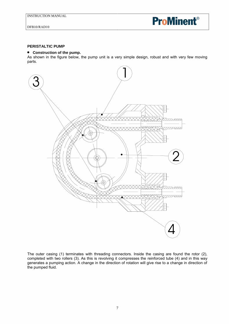
PERISTALTIC PUMP
Construction of the pump.As shown in the figure below, the pump unit is a very simple design, robust and with very few movingparts.
The outer casing (1) terminates with threading connectors. Inside the casing are found the rotor (2), completed with two rollers (3). As this is revolving it compresses the reinforced tube (4) and in this way generates a pumping action. A change in the direction of rotation will give rise to a change in direction of the pumped fluid.
DFB10/RAD10

INSTRUCTION MANUAL
8
INSTALLATION
Installation should normally be made in a well ventilated area away from heat sources. If it isnecessary to place the pump outside it should be provided with a cover to protect it from sunlight andinclement weather.
The positioning of the pump should allow easy access for all kinds of maintenance operations.
Suction. The pump should be as near as possible to the supply of liquid so that the suction pipe is as short and straight as possible. The suction pipe should be perfectly airtight and made of suitable material so that it does not collapse due to the internal drop in vacuum. The minimum diameter should be similar to that of the tubular element. With viscous fluids a larger diameter is recommendable. (Consult manufacturer or
distributor). The pump has automatic suction and does not need an inlet valve. The pump is reversible, and so the suction connection can be either one of the two. (Normally the one which adapts itself physically better to the installation would be chosen). It is recommendable to use a flexible connection between the piping and the pump flanges/fittings of the pump in order to avoid the transmission of vibration to the piping.
Discharge. To reduce power being absorbed, use the straightest and shortest piping possible. The diameter should be the same as the nominal diameter of the pump, excepting precise calculations of load losses. With viscous fluids a larger diameter is needed. (Consult the manufacturer or distributor). Connecting the fixed piping to the pump with a length of flexible pipe facilitates maintenance and avoids vibrations and loads on the pump. Tighten all piping firmly. The discharge is slightly pulsatory: To avoid such effect, it is advisable to install pulsation dampeners. (See accessories.)
ROLLER PRESSURE ADJUSTMENT
The peristaltic pump, includes a shims (Figure 6 ), that are used to adjust the exact pressing distance of the roller (figure 9).
6
9
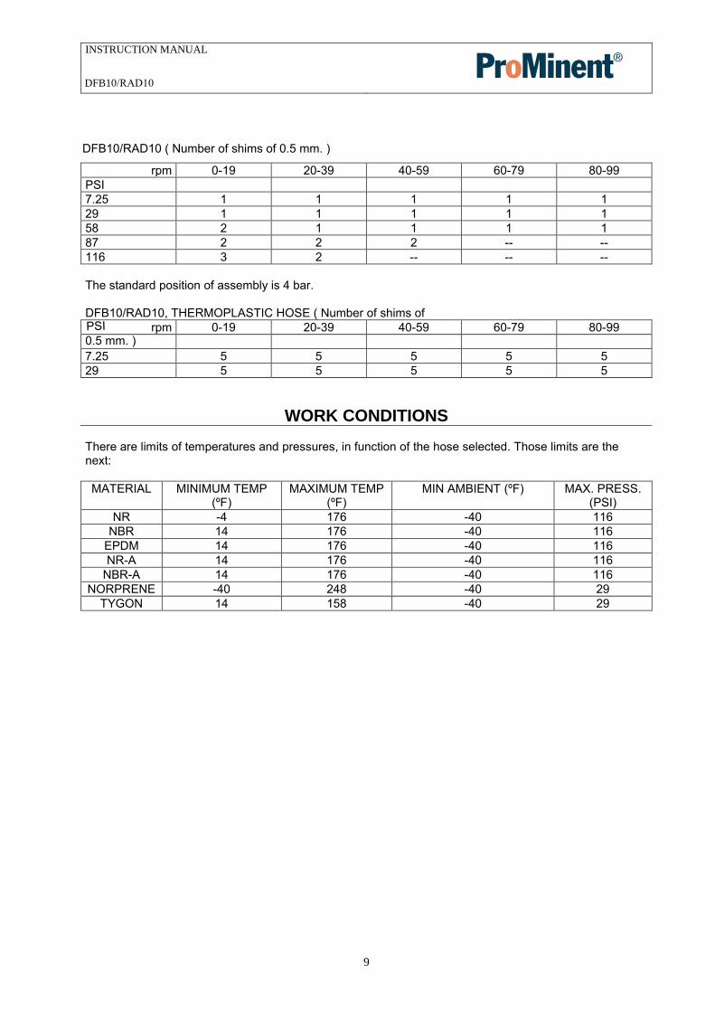
The shims are installed from factory to work at the work conditions indicated (in function of the speed and the work pressure), and following the next tables. NOTE: if not indicated on original order, the pumps are factory set to 60 psi.
DFB10/RAD10
INSTRUCTION MANUAL
9
rpm 0-19 20-39 40-59 60-79 80-99PSI 7.25 1 1 1 1 1 29 1 1 1 1 1 58 2 1 1 1 1 87 2 2 2 -- -- 116 3 2 -- -- --
The standard position of assembly is 4 bar.
DFB10/RAD10, THERMOPLASTIC HOSE ( Number of shims of
0.5 mm. ) rpm 0-19 20-39 40-59 60-79 80-99PSI
7.25 5 5 5 5 5 29 5 5 5 5 5
WORK CONDITIONS
There are limits of temperatures and pressures, in function of the hose selected. Those limits are the next:
MATERIAL MINIMUM TEMP (ºF)
MAXIMUM TEMP (ºF)
MIN AMBIENT (ºF) MAX. PRESS. (PSI)
NR -4 176 -40 116 NBR 14 176 -40 116
EPDM 14 176 -40 116 NR-A 14 176 -40 116
NBR-A 14 176 -40 116 NORPRENE -40 248 -40 29
TYGON 14 158 -40 29
DFB10/RAD10 ( Number of shims of 0.5 mm. )
DFB10/RAD10

INSTRUCTION MANUAL
10
PERFORMANCE CURVES
DFB10/RAD10
DFB10/RAD10
INSTRUCTION MANUAL
11
DFB10/RAD10
INSTRUCTION MANUAL
12
CHECKS BEFORE SWITCHING ON THE PUMP
Check that the pumping equipment has not suffered any damage during transportation or storage, any damage should be notified to the supplier immediately.
Check that the network voltage is suitable for the motor.
Make sure that the hose is suitable for the fluid to be pumped and that it will not be chemically affected, check also that the temperature of the fluid does not exceed that recommended. If the hose is in a resting position, then the pump has come from storage or transportation; now is the moment to install the second roller. Do not switch on the pump without the front cover beingcorrectly installed.
Lubrication. Check that the drive pump and the inner of the rollers are correctly greased. The specially formulated grease can be obtained from the authorized distributor.
Check that the protectors of the moving parts are correctly assembled.
Check that the thermal protector corresponds with that of the values on the plate on the motor.
Check that the direction of rotation is the desired one. (rotation test).
Check that the optional electrical components are connected to the control panel and test that they function correctly.
In cases of doubt of the valuation of discharge pressure (e.g. high viscosity), mount a pressure gauge on the discharge.
Check in predicted working conditions that the values of flow, pressure and absorbed power of the motor correspond to the project.
MAINTENANCE
Any work carried out on the pump must be done when the pump is stationary and disconnected from the electricity supply.
Lubrication
Check that the rollers and the hose are correctly greased. Check it every 200 hours of work. Add silicon grease as necessary.
Check that the lubricant level in the gear reducer is correct and carry out periodic changes of lubricant according to the maintenance manual.
DFB10/RAD10
INSTRUCTION MANUAL
13
REPOSITIONING OF HOSE - DISMANTLING
First, all valves must be closed to prevent losses of the product.
Disconnect the suction and discharge pipes.
Dismantling of the suction/discharge connections. Dismantling of the rollers that compress the drivepump. Remove the tube to be replaced and separate the connections from both pipe ends.
REPOSITIONING OF HOSE - MOUNTING
Clean the internal surfaces of the pump body. Lubricate the internal faces of the body of the pumpwhere there could be friction with the hose. To carry out this operation correctly it is necessary toremove the front cover.
Inspect the rollers, checking that there is no damage to the pressure surface. If the machine is beingset up for the first time, see paragraph Rotor in the section CHECKS BEFORE SWITCHING ON THEPUMP.
Insert the connections in each hose end.
Install the hose in the pump body, lubricating with silicon grease the hose and the inner of the rollers.
Mount the tightening collars that fasten the hose and its connections to the pump body.
Fit the rollers.
Fit the front cover.
Connect suction/discharge pipes.
DFB10/RAD10

INSTRUCTION MANUAL
14
PROBLEMS, CAUSES AND SOLUTIONS
PROBLEM POSSIBLE CAUSE SOLUTIÓN Elevated temperature
Hose with no lubricant Elevated temperature of product Poor or bad suction conditions
Excessive pipe tightening
Excessive pumping speed
Use original silicon greaseReduce pumping temperature Check there are no obstructions Recalculate sections and lengths Check rollers shaft mounting
Reduce velocity of pump Reduction of capacity/pressure
Suction or discharge valve closed. Hose insufficiently compressed
Rupture of the hose (the product leaks to the casing) Partial obstruction of suction piping Insufficient product amount in suction reservoir Insufficient diameter of suction piping Excessive length of suction pipe High viscosity of product
Entry of air via the suction connections High pulsation on suction
Open valves Check rollers shaft mounting and check for correct number of shims. Replace drive hose
Clean piping Fill or stop Increase section length/reduce pump speed Shorten suction piping Reduce viscosity Increase section length of piping Confirm that the pump is suitable Tighten connections and accessories Install pulsation dampener to discharge Reconsider application (speed etc.)
Vibrations in pump and piping
The piping is not correctly fixed together Excessive pumping speed
Insufficient diameter of piping Bedplate of pump loose Elevated pulsation of pump
Check all piping connections Reduce the speed of the pump
Increase pipe diameter Fix the bedplate firmly Install pulsation dampener to discharge
Short life of the hose
Chemical attack
High speed of pump High pumping temperature High working pressure
Abnormal elevation of temperature Unsuitable lubricant Insufficient quantity of grease Cavitation of the pump
Confirm compatibility of the hose with the pumped fluid and the cleaning fluid Reduce speed of pump Reduce temperature of product Reduce speed of pump Increase section diameter of piping Check rollers shaft mounting Use original silicon grease Apply silicon grease Adjust suction conditions
Stretching of the hose inside the pump
Insufficient grease High suction pressures (>3 Bar) Hose full of sediment Brackets insufficiently tightened
Add silicon grease to hose/tube Reduce suction pressure Clean hose Retighten brackets
The pump does not start
Insufficient starter power Insufficient power from frequency convertor
Blockage in the pump
Increase starter power Increase power Check that the voltage is adequate Do not drop below a frequency of 1Hz (confirm this point with the distributor)
Check there are no obstructions in the pipe
DFB10/RAD10
INSTRUCTION MANUAL
DFB10/RAD10
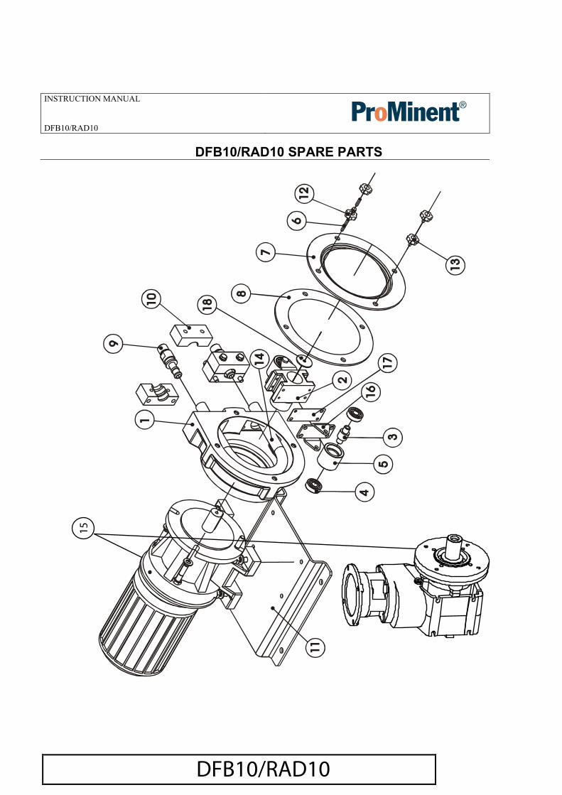
DFB10/RAD10 SPARE PARTS
DFB10/RAD10
15
INSTRUCTION MANUAL
16
DECLARATION OF CONFORMITY
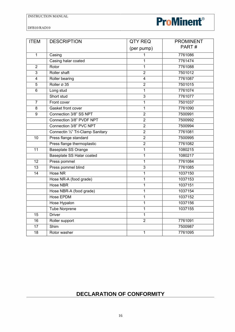
ITEM DESCRIPTION QTY REQ (per pump)
PROMINENT PART #
1 Casing 1 7761086 Casing halar coated 1 7761474
2 Rotor 1 7761088 3 Roller shaft 2 7501012 4 Roller bearing 4 7761087 5 Roller Ø 35 2 7501015 6 Long stud 1 7761074
Short stud 3 7761077 7 Front cover 1 7501037 8 Gasket front cover 1 7761090 9 Connection 3/8” SS NPT 2 7500991
Connection 3/8” PVDF NPT 2 7500992 Connection 3/8” PVC NPT 2 7500994 Connectin ½” Tri-Clamp Sanitary 2 7761081
10 Press flange standard 2 7500995 Press flange thermoplastic 2 7761082
11 Baseplate SS Orange 1 1080215 Baseplate SS Halar coated 1 1080217
12 Press pommel 1 7761084 13 Press pommel blind 3 7761085 14 Hose NR 1 1037150
Hose NR-A (food grade) 1 1037153 Hose NBR 1 1037151 Hose NBR-A (food grade) 1 1037154 Hose EPDM 1 1037152 Hose Hypalon 1 1037156 Tube Norprene 1 1037155
15 Driver 1 16 Roller support 2 7761091 17 Shim 7500987 18 Rotor washer 1 7761095
DFB10/RAD10

INSTRUCTION MANUAL
17
The company:
Declares under its own sole responsibility that the next industrial
peristaltic pump: Model: DFB10/RAD10Serial number:
CE DECLARATION OF CONFORMITY (Ann. II.A, 98/37/CE)
The pump is conform to the safety requirements according to the 98/37/CE norms and
amendments.
MANUFACTURER DECLARATION (Ann. II.B, 98/37/CE)
The pump cannot be operated before the machine in which is assembled the pump, will
be declared in conformity with the safety requirements according to the 98/37/CE norms
and amendments.
FOOD PRODUCTS-CONTACT SUITABILITY DECLARATION
The pump is made with materials suitable to come in contact with food grade product
according to the 89/109/EEC norms and amendments.
on:
The technical Director.
GUARANTEE
DFB10/RAD10

INSTRUCTION MANUAL
18
- The contractor shall obtain from the manufacturer its warranty that theequipment shall be warranted for a period of one (1) year from the date ofstart-up or 18 months from signed delivery acknowledgement, whichevercomes first, to be free from defects in materials and workmanship. Thisguarantee does not include the hose or the lubricant as these are elementsthat have a normal function wear, irrespective of their duration.
- This guarantee is valid as long as the equipment functions within theparameters indicated in the technical information card supplied with everypump or on subsequent changes authorised.
- This guarantee includes materials and work but not the transportation ofmaterials to or from our warehouses, being necessary to do so arising fromthe necessities of the client, the corresponding costs of displacement andexpenses will be charged.
DFB10/RAD10