Embed Size (px)
Citation preview
Vol-4 Issue-2 2018 IJARIIE-ISSN(O)-2395-4396
7930 www.ijariie.com 2406
DUAL SIDE DOUBLE ACTING WATER
PUMPING SYSTEM USING SCOTCH YOKE
MECHANISM
S.Jerome Ubahara Clinton1, E.Prem kumar
2, P.PremKumar
3,S.Prethiviraj
4,S.Raghuvaran
5
1234 UG Students ,Department of Mechanical Engineering,
5Assistant Professor,Department of Mechanical Engineering,
K.Ramakrishnan College of Engineering ,Trichy -621112 .
E MAIL ID: [email protected],[email protected]
ABSTRACT
The aim of the project is fabrication of dual side water pump. dual side water pump using scotch yoke
mechanisms are reciprocating pump in which the plunger is provided for the pumping action. The plunger is
reciprocated with the help of a cam plate . By this action the water is pumped to very high pressure. This can be
utilized for various applications. The cam plate gets the drive from the motor. Thus the operation is done.
KEYWORD: Scotch yoke mechanism, Dual side, Double acting
1.INTRODUCTION
A pump is a Mechanical device which converts mechanical energy into hydraulic energy. This pump is
classified into two types;
i. Positive Displacement and
ii. Non-Positive Displacement pump
In positive displacement pump is the one, in which the liquid is transferred positively from one stage to
another stage by the to and fro motion of the plunger or piston of the pump. In non-positive displacement pump the
liquid is transferred by the centrifugal force. This force is cause due to the rotary movement of an impeller. In this,
our project, radial plunger pump is of positive displacement pump. The salient features of a Radial plunger pump
have been retained in our project model and this has been achieved with great care. Due to high precision work
involved in producing radial plunger pump besides higher cost these pumps are not widely manufactured by most of
the industries. The very name itself indicates that it works with the help of a plunger. This plunger is reciprocated
with the help of a cam shaft. This is rotated by the motor. The camshaft is the heart of this pump The plunger reciprocated does the pumping action. The oil in the tank at normal pressure is delivered to a very high pressure after
pumping This high pressure oil is utilised for various purpose like lifting, load transferring etc..
2. DESCRIPTION OF EQUIPMENT
2.1 MOTOR
2.1.1 D.C.MOTOR PRINCIPLE
Vol-4 Issue-2 2018 IJARIIE-ISSN(O)-2395-4396
7930 www.ijariie.com 2407
A machine that converts direct current power into mechanical power is known as D.C Motor. Its generation
is based on the principle that when a current carrying conductor is placed in a magnetic field, the conductor
experiences a mechanical force. The direction iof this force is given by Fleming’s left hand rule.
2.1.2 WORKING OF A DC MOTOR
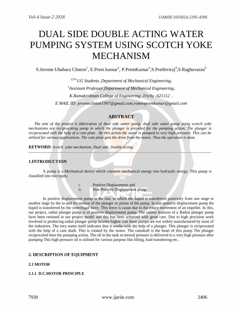
Consider a part of a multipolar dc motor as shown in fig. when the terminals of the motor are connected to an
external source of dc supply;
(i) The field magnets are excited developing alternate N and S poles.
(ii) The armature conductors carry currents. All conductors under N-pole carry currents in one direction
while all the conductors under S-pole carry currents in the opposite direction.
Suppose the conductors under N-pole carry currents into the plane of paper and those under S-pole carry current
out of the plane of paper as shown in fig. Since each armature conductor is carrying current and is placed in the
magnetic field, mechanical force acts on it. Applying Fleming’s left hand rule, it is clear that force on each
conductor is tending to rotate the armature in anticlockwise direction. All these forces add together to produce a
driving torque which sets the armature rotating. When the conductor moves from one side of the brush to the other,
current in the conductor is received and at the same time it comes under the influence of next pole which is of
opposite polarity. Consequently the direction of force on the conductor remains same.
Vol-4 Issue-2 2018 IJARIIE-ISSN(O)-2395-4396
7930 www.ijariie.com 2408
2.1.3 PRINCIPLES OF OPERATION:
In any electric motor, operation is based on simple electromagnetism. A current-carrying conductor
generates a magnetic field; when this is then placed in an external magnetic field, it will experience a force
proportional to the current in the conductor, and to the strength of the external magnetic field. As you are well aware
of from playing with magnets as a kid, opposite (North and South) polarities attract, while like polarities (North and
North, South and South) repel. The internal configuration of a DC motor is designed to harness the magnetic interaction between a current-carrying conductor and an external magnetic field to generate rotational motion.
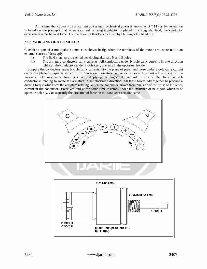
Let's start by looking at a simple 2-pole DC electric motor (here red represents a magnet or winding with a
"North" polarization, while green represents a magnet or winding with a "South" polarization).
Every DC motor has six basic parts -- axle, rotor (armature), stator, commutator, field magnet(s), and
brushes. In most common DC motors, the external magnetic field is produced by high-strength permanent magnets.
The stator is the stationary part of the motor -- this includes the motor casing, as well as two or more permanent
magnet pole pieces. The rotor (together with the axle and attached commutator) rotates with respect to the stator.
The rotor consists of windings (generally on a core), the windings being electrically connected to the commutator.
The above diagram shows a common motor layout -- with the rotor inside the stator (field) magnets.
The geometry of the brushes, commutator contacts, and rotor windings are such that when power is applied,
the polarities of the energized winding and the stator magnet(s) are misaligned, and the rotor will rotate until it is
almost aligned with the stator's field magnets. As the rotor reaches alignment, the brushes move to the next commutator contacts, and energize the next winding. Given our example two-pole motor, the rotation reverses the
direction of current through the rotor winding, leading to a "flip" of the rotor's magnetic field, driving it to continue
rotating.
In real life, though, DC motors will always have more than two poles (three is a very common number). In
particular, this avoids "dead spots" in the commutator. You can imagine how with our example two-pole motor, if
the rotor is exactly at the middle of its rotation (perfectly aligned with the field magnets), it will get "stuck" there.
Meanwhile, with a two-pole motor, there is a moment where the commutator shorts out the power supply. This
would be bad for the power supply, waste energy, and damage motor components as well. Yet another disadvantage
of such a simple motor is that it would exhibit a high amount of torque "ripple" (the amount of torque it could
produce is cyclic with the position of the rotor).
Vol-4 Issue-2 2018 IJARIIE-ISSN(O)-2395-4396
7930 www.ijariie.com 2409
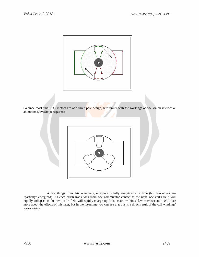
So since most small DC motors are of a three-pole design, let's tinker with the workings of one via an interactive
animation (JavaScript required):
A few things from this -- namely, one pole is fully energized at a time (but two others are
"partially" energized). As each brush transitions from one commutator contact to the next, one coil's field will
rapidly collapse, as the next coil's field will rapidly charge up (this occurs within a few microsecond). We'll see
more about the effects of this later, but in the meantime you can see that this is a direct result of the coil windings'
series wiring:
Vol-4 Issue-2 2018 IJARIIE-ISSN(O)-2395-4396
7930 www.ijariie.com 2410
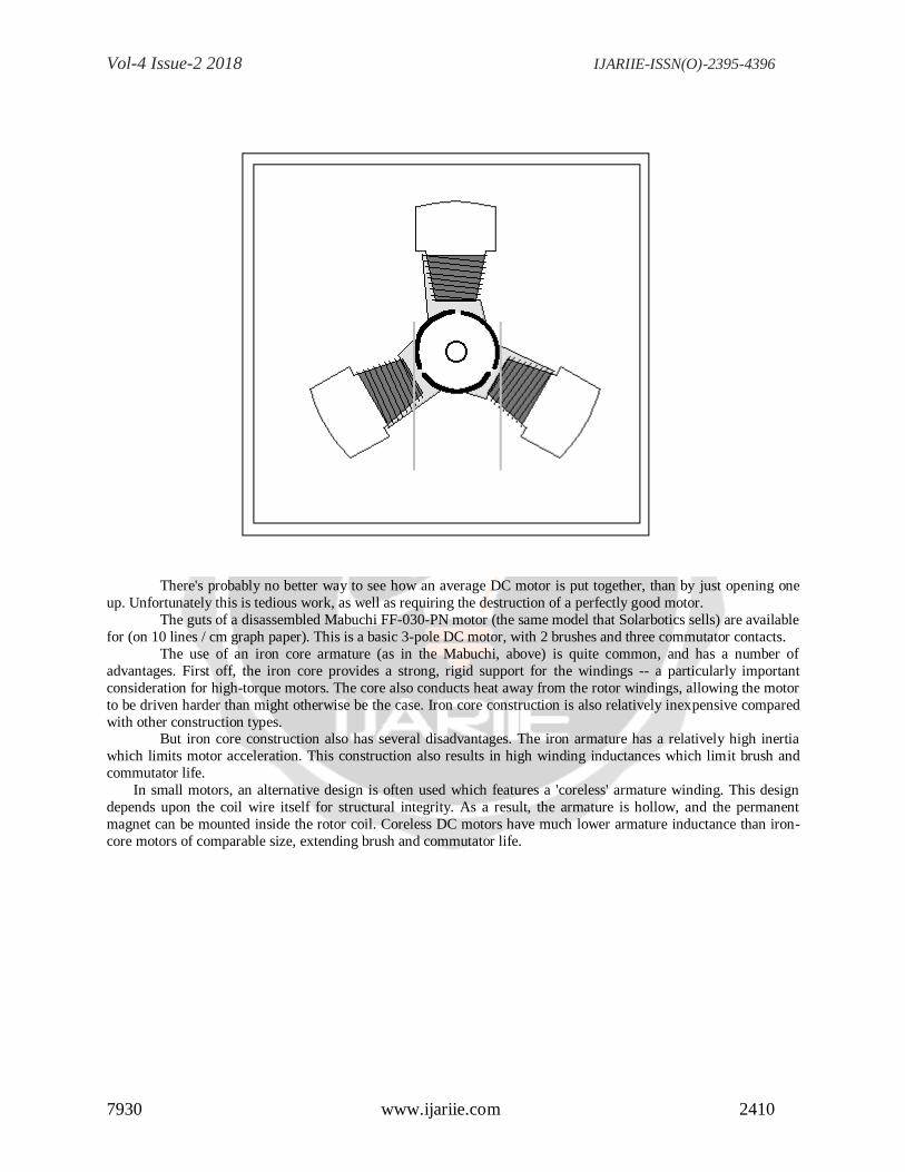
There's probably no better way to see how an average DC motor is put together, than by just opening one
up. Unfortunately this is tedious work, as well as requiring the destruction of a perfectly good motor.
The guts of a disassembled Mabuchi FF-030-PN motor (the same model that Solarbotics sells) are available
for (on 10 lines / cm graph paper). This is a basic 3-pole DC motor, with 2 brushes and three commutator contacts.
The use of an iron core armature (as in the Mabuchi, above) is quite common, and has a number of
advantages. First off, the iron core provides a strong, rigid support for the windings -- a particularly important
consideration for high-torque motors. The core also conducts heat away from the rotor windings, allowing the motor
to be driven harder than might otherwise be the case. Iron core construction is also relatively inexpensive compared
with other construction types. But iron core construction also has several disadvantages. The iron armature has a relatively high inertia
which limits motor acceleration. This construction also results in high winding inductances which limit brush and
commutator life.
In small motors, an alternative design is often used which features a 'coreless' armature winding. This design
depends upon the coil wire itself for structural integrity. As a result, the armature is hollow, and the permanent
magnet can be mounted inside the rotor coil. Coreless DC motors have much lower armature inductance than iron-
core motors of comparable size, extending brush and commutator life.
Vol-4 Issue-2 2018 IJARIIE-ISSN(O)-2395-4396
7930 www.ijariie.com 2411
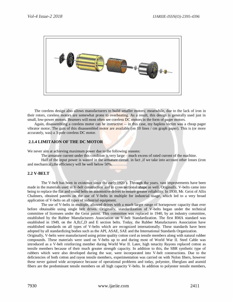
The coreless design also allows manufacturers to build smaller motors; meanwhile, due to the lack of iron in
their rotors, coreless motors are somewhat prone to overheating. As a result, this design is generally used just in
small, low-power motors. Beamers will most often see coreless DC motors in the form of pager motors.
Again, disassembling a coreless motor can be instructive -- in this case, my hapless victim was a cheap pager
vibrator motor. The guts of this disassembled motor are available (on 10 lines / cm graph paper). This is (or more accurately, was) a 3-pole coreless DC motor.
2.1.4 LIMITAION OF THE DC MOTOR
We never aim at achieving maximum power due to the following reasons:
The armature current under this condition is very large – much excess of rated current of the machine. Half of the input power is wasted in the armature circuit. in fact ,if we take into account other losses (iron
and mechanical),the efficiency will be well below 50%.
2.2 V-BELT
The V-belt has been in existence since the early 1920’s. Through the years, vast improvements have been
made in the materials used in V-belt construction and in cross sectional shape as well. Originally, V-belts came into being to replace the flat and round belts on automotive drives to ensure greater reliability. In 1930, Mr. Geist of Allis
Chalmers, obtained patents on the use of V-belts in multiple for industrial usage, which led to a very broad
application of V-belts on all types of industrial equipment.
The use of V-belts in multiple, allowed drives with a much larger range of horsepower capacity than ever
before obtainable using single belt drives. Originally, standardization of V-belts began under the technical
committee of licensees under the Geist patent. This committee was replaced in 1940, by an industry committee,
established by the Rubber Manufacturers Association on V-belt Standardization. The first RMA standard was
established in 1949, on the A,B,C,D and E section belts. Today, the Rubber Manufacturers Association have
established standards on all types of V-belts which are recognized internationally. These standards have been
adopted by all standardizing bodies such as the API, ASAE, SAE and the International Standards Organization.
Originally, V-belts were manufactured using prime quality cotton cord as tensile members along with natural rubber
compounds. These materials were used on V-belts up to and during most of World War II. Steel Cable was introduced as a V-belt reinforcing member during World War II. Later, high tenacity Rayons replaced cotton as
tensile members because of their much greater strength capacity. In addition to this, the SBR synthetic type of
rubbers which were also developed during the war, were incorporated into V-belt constructions. Due to the
deficiencies of both cotton and rayon tensile members, experimentation was carried on with Nylon fibers, however
these never gained wide acceptance because of operational problems and today, polyester, fiberglass and aramid
fibers are the predominant tensile members on all high capacity V-belts. In addition to polyester tensile members,
Vol-4 Issue-2 2018 IJARIIE-ISSN(O)-2395-4396
7930 www.ijariie.com 2412
the Neoprene type of elastomers have become widely used because of their much greater resistance to oil, heat, and
ozone resistance
In addition to changes in materials, changes in belt cross-sections have occured to obtain greater
horsepower in less space. This was originally introduced with the ―narrow‖ type belt on cars in 1950. This more
efficient, space saving design was further refined for industrial use with the introduction of 3V,5V and 8V belts in
1959. This new cross section design featured a domed top with increased sidewall area, providing greater horsepower capacity in less space. More recently Joined, V-Ribbed and Raw Edge belting have gained widespread
acceptance.
2.2.1V-BELT DRIVE ADVANTAGES
Efficiency tests of Carlisle multiple V-belt drives have shown them to be 94 - 98% efficient. Because of the
wide variety of belt sizes available, almost any type of drive application can be designed using stock standard items. This ensures availability and excellent delivery schedules and if necessary, special constructions are available for
unusual applications. Carlisle V-belt drives also provide many advantages that help reduce equipment repairs and
hold forced downtime to the lowest possible level.
Other significant advantages include:
• Smooth starting and running.
• Permit a wide range of driven speeds, using standard electric motors.
• They’re rugged and provide years of trouble-free performance with minimal attention . . . even under adverse
conditions.
• Capable of transmitting power around corners or out of plane drives.
• Clean—require no lubrication. • Highly efficient.
• Extremely wide horsepower ranges.
• Dampen vibration between driver and driven machines.
• Silent operation.
• Long service life.
• Easy installation.
• Can be used as an effective means of clutching.
• They act as a ―safety fuse‖ refusing to transmit severe power overload, except for a very brief period.
• V-belts and sheaves wear gradually-making preventive corrective maintenance simple and easy.
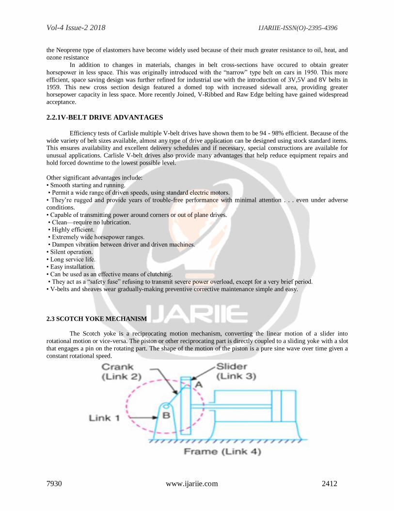
2.3 SCOTCH YOKE MECHANISM
The Scotch yoke is a reciprocating motion mechanism, converting the linear motion of a slider into
rotational motion or vice-versa. The piston or other reciprocating part is directly coupled to a sliding yoke with a slot
that engages a pin on the rotating part. The shape of the motion of the piston is a pure sine wave over time given a
constant rotational speed.
Vol-4 Issue-2 2018 IJARIIE-ISSN(O)-2395-4396
7930 www.ijariie.com 2413
This mechanism is used for converting rotary motion into a reciprocating motion. The inversion is obtained
by fixing either the link 1 or link 3. In Fig, link 1 is fixed. In this mechanism, when the link 2 (which corresponds to
crank) rotates about B as centre, the link 4 (which corresponds to a frame) reciprocates. The fixed link 1 guides the
frame.
2.4 CAM
2.4.1 Cam arrangement
A cam is a rotating or sliding piece in a mechanical linkage used especially in transforming rotary motion
into linear motion or vice-versa. It is often a part of a rotating wheel (e.g. an eccentric wheel) or shaft (e.g. a cylinder
with an irregular shape) that strikes a lever at one or more points on its circular path. The cam can be a simple tooth,
as is used to deliver pulses of power to a steam hammer, for example, or an eccentric disc or other shape that
produces a smooth reciprocating (back and forth) motion in the follower, which is a lever making contact with the
cam. The cam can be seen as a device that rotates from circular to reciprocating (or sometimes oscillating) motion.
A common example is the camshaft of an automobile, which takes the rotary motion of the engine and translates it
into the reciprocating motion necessary to operate the intake and exhaust valves of the cylinders. Cams can also be
viewed as information-storing and transmitting devices. Examples are the cam-drums that direct the notes of a
musical box or the movements of a screw machine's various tools and chucks. The information stored and transmitted by the cam
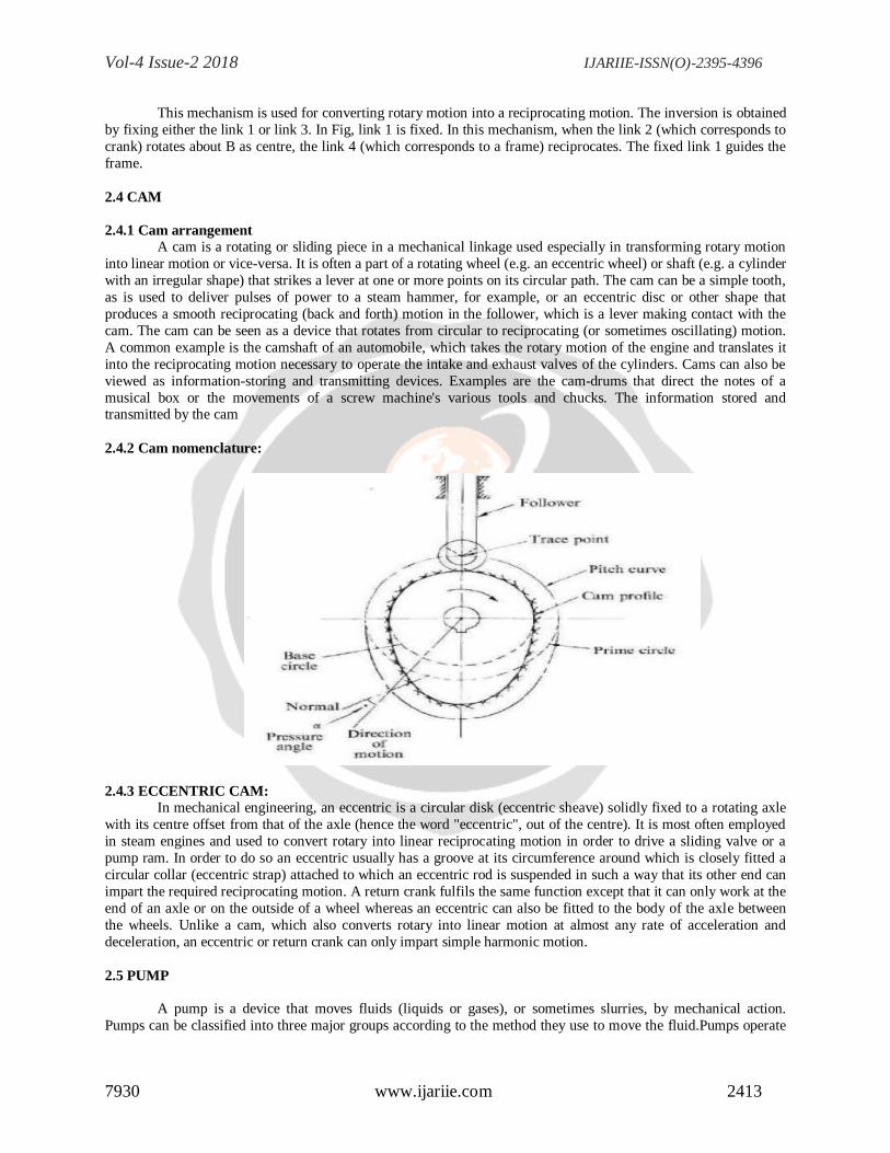
2.4.2 Cam nomenclature:
2.4.3 ECCENTRIC CAM:
In mechanical engineering, an eccentric is a circular disk (eccentric sheave) solidly fixed to a rotating axle
with its centre offset from that of the axle (hence the word "eccentric", out of the centre). It is most often employed
in steam engines and used to convert rotary into linear reciprocating motion in order to drive a sliding valve or a
pump ram. In order to do so an eccentric usually has a groove at its circumference around which is closely fitted a
circular collar (eccentric strap) attached to which an eccentric rod is suspended in such a way that its other end can
impart the required reciprocating motion. A return crank fulfils the same function except that it can only work at the
end of an axle or on the outside of a wheel whereas an eccentric can also be fitted to the body of the axle between
the wheels. Unlike a cam, which also converts rotary into linear motion at almost any rate of acceleration and
deceleration, an eccentric or return crank can only impart simple harmonic motion.
2.5 PUMP
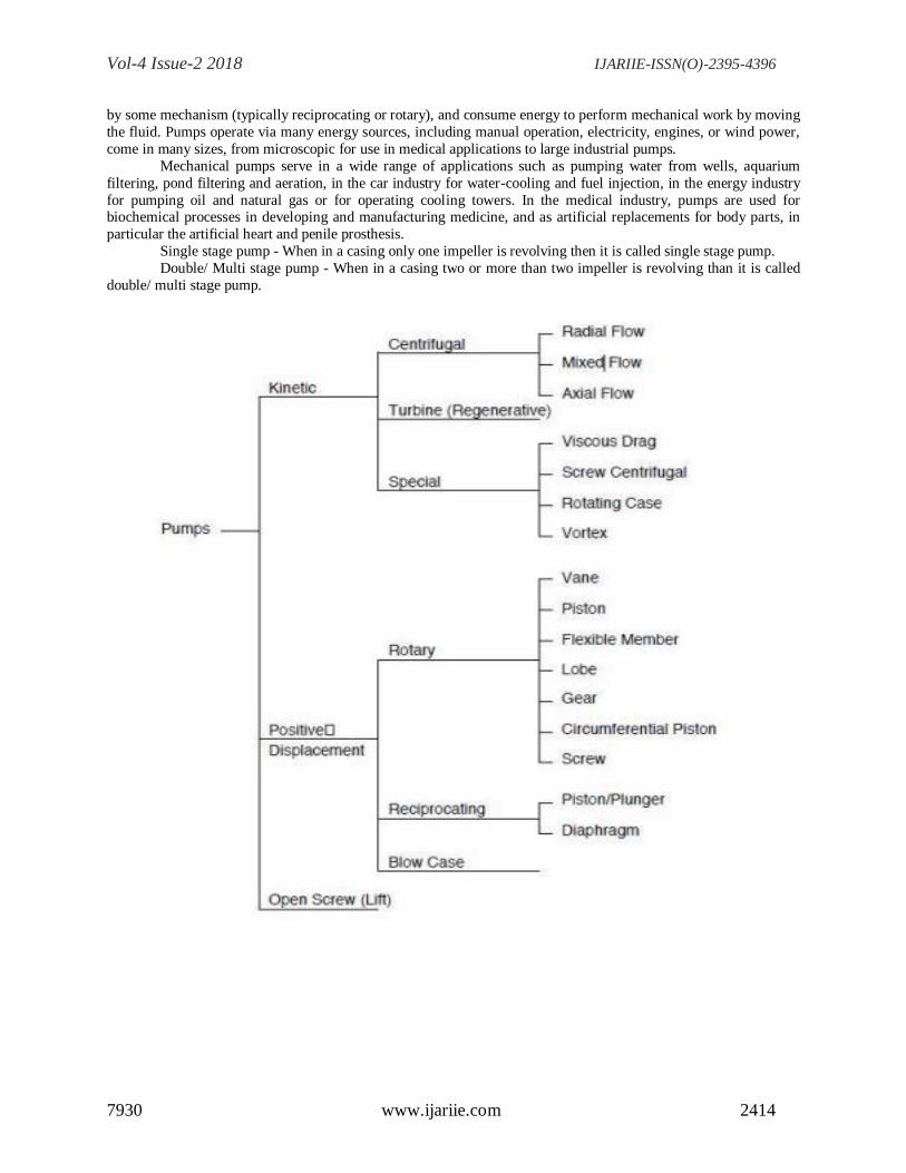
A pump is a device that moves fluids (liquids or gases), or sometimes slurries, by mechanical action.
Pumps can be classified into three major groups according to the method they use to move the fluid.Pumps operate
Vol-4 Issue-2 2018 IJARIIE-ISSN(O)-2395-4396
7930 www.ijariie.com 2414
by some mechanism (typically reciprocating or rotary), and consume energy to perform mechanical work by moving
the fluid. Pumps operate via many energy sources, including manual operation, electricity, engines, or wind power,
come in many sizes, from microscopic for use in medical applications to large industrial pumps.
Mechanical pumps serve in a wide range of applications such as pumping water from wells, aquarium
filtering, pond filtering and aeration, in the car industry for water-cooling and fuel injection, in the energy industry
for pumping oil and natural gas or for operating cooling towers. In the medical industry, pumps are used for biochemical processes in developing and manufacturing medicine, and as artificial replacements for body parts, in
particular the artificial heart and penile prosthesis.
Single stage pump - When in a casing only one impeller is revolving then it is called single stage pump.
Double/ Multi stage pump - When in a casing two or more than two impeller is revolving than it is called
double/ multi stage pump.
Vol-4 Issue-2 2018 IJARIIE-ISSN(O)-2395-4396
7930 www.ijariie.com 2415
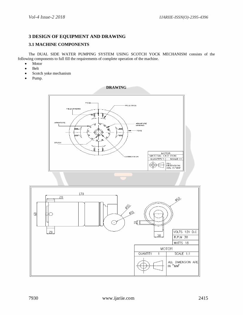
3 DESIGN OF EQUIPMENT AND DRAWING
3.1 MACHINE COMPONENTS
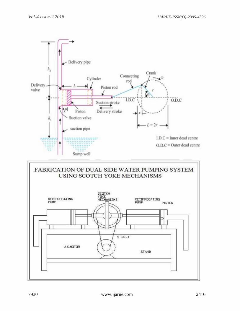
The DUAL SIDE WATER PUMPING SYSTEM USING SCOTCH YOCK MECHANISM consists of the
following components to full fill the requirements of complete operation of the machine.
Motor
Belt
Scotch yoke mechanism
Pump.
DRAWING
Vol-4 Issue-2 2018 IJARIIE-ISSN(O)-2395-4396
7930 www.ijariie.com 2416
Vol-4 Issue-2 2018 IJARIIE-ISSN(O)-2395-4396
7930 www.ijariie.com 2417
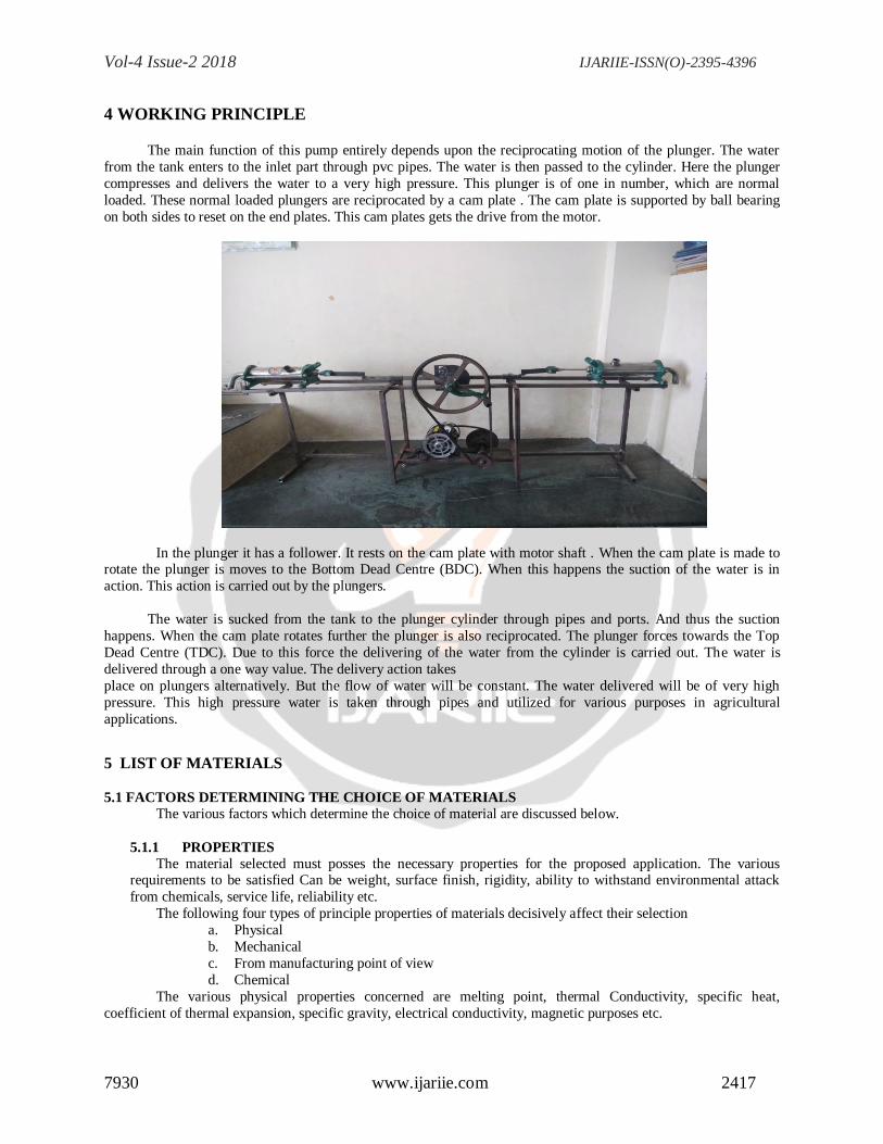
4 WORKING PRINCIPLE
The main function of this pump entirely depends upon the reciprocating motion of the plunger. The water
from the tank enters to the inlet part through pvc pipes. The water is then passed to the cylinder. Here the plunger
compresses and delivers the water to a very high pressure. This plunger is of one in number, which are normal
loaded. These normal loaded plungers are reciprocated by a cam plate . The cam plate is supported by ball bearing
on both sides to reset on the end plates. This cam plates gets the drive from the motor.
In the plunger it has a follower. It rests on the cam plate with motor shaft . When the cam plate is made to rotate the plunger is moves to the Bottom Dead Centre (BDC). When this happens the suction of the water is in
action. This action is carried out by the plungers.
The water is sucked from the tank to the plunger cylinder through pipes and ports. And thus the suction
happens. When the cam plate rotates further the plunger is also reciprocated. The plunger forces towards the Top
Dead Centre (TDC). Due to this force the delivering of the water from the cylinder is carried out. The water is
delivered through a one way value. The delivery action takes
place on plungers alternatively. But the flow of water will be constant. The water delivered will be of very high
pressure. This high pressure water is taken through pipes and utilized for various purposes in agricultural
applications.
5 LIST OF MATERIALS
5.1 FACTORS DETERMINING THE CHOICE OF MATERIALS
The various factors which determine the choice of material are discussed below.
5.1.1 PROPERTIES
The material selected must posses the necessary properties for the proposed application. The various requirements to be satisfied Can be weight, surface finish, rigidity, ability to withstand environmental attack
from chemicals, service life, reliability etc.
The following four types of principle properties of materials decisively affect their selection
a. Physical
b. Mechanical
c. From manufacturing point of view
d. Chemical
The various physical properties concerned are melting point, thermal Conductivity, specific heat,
coefficient of thermal expansion, specific gravity, electrical conductivity, magnetic purposes etc.
Vol-4 Issue-2 2018 IJARIIE-ISSN(O)-2395-4396
7930 www.ijariie.com 2418
The various Mechanical properties Concerned are strength in tensile, Compressive shear, bending,
torsional and buckling load, fatigue resistance, impact resistance, eleastic limit, endurance limit, and modulus of
elasticity, hardness, wear resistance and sliding properties. The various properties concerned from the manufacturing
point of view are,
Cast ability
Weld ability Bribability
Forge ability
Merchantability
Surface properties
Shrinkage
Deep drawing etc.
5.1.2 MANUFACTURING CASE
Sometimes the demand for lowest possible manufacturing cost or surface qualities obtainable by the application
of suitable coating substances may demand the use of special materials.
5.1.3 QUALITY REQUIRED
This generally affects the manufacturing process and ultimately the material. For example, it would never
be desirable to go casting of a less number of components which can be fabricated much more economically by
welding or hand forging the steel.
5.1.4 AVAILABILITY OF MATERIAL
Some materials may be scarce or in short supply.it then becomes obligatory for the designer to use some
other material which though may not be a perfect substitute for the material designed.the delivery of materials and
the delivery date of product should also be kept in mind.
5.1.5 SPACE CONSIDERATION
Sometimes high strength materials have to be selected because the forces involved are high and space
limitations are there.
5.1.6 COST
As in any other problem, in selection of material the cost of material plays an important part and should not
be ignored.
Some times factors like scrap utilization, appearance, and non-maintenance of the designed part are
involved in the selection of proper materials.
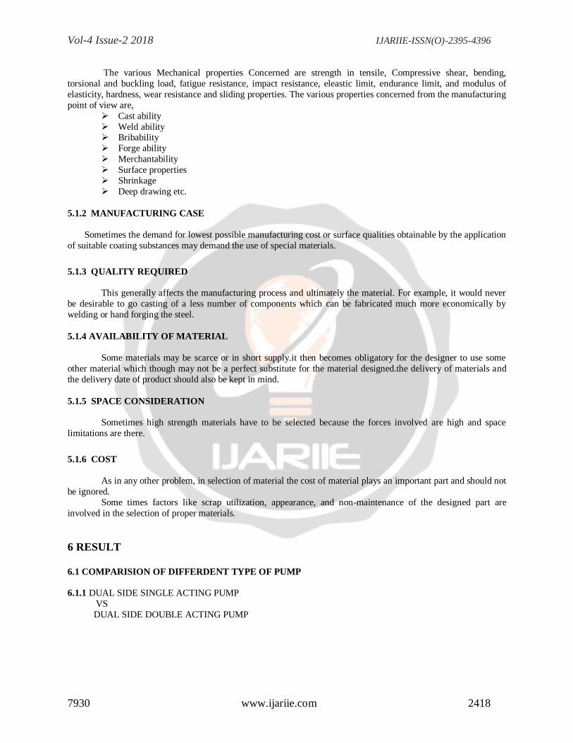
6 RESULT
6.1 COMPARISION OF DIFFERDENT TYPE OF PUMP
6.1.1 DUAL SIDE SINGLE ACTING PUMP
VS
DUAL SIDE DOUBLE ACTING PUMP
Vol-4 Issue-2 2018 IJARIIE-ISSN(O)-2395-4396
7930 www.ijariie.com 2419
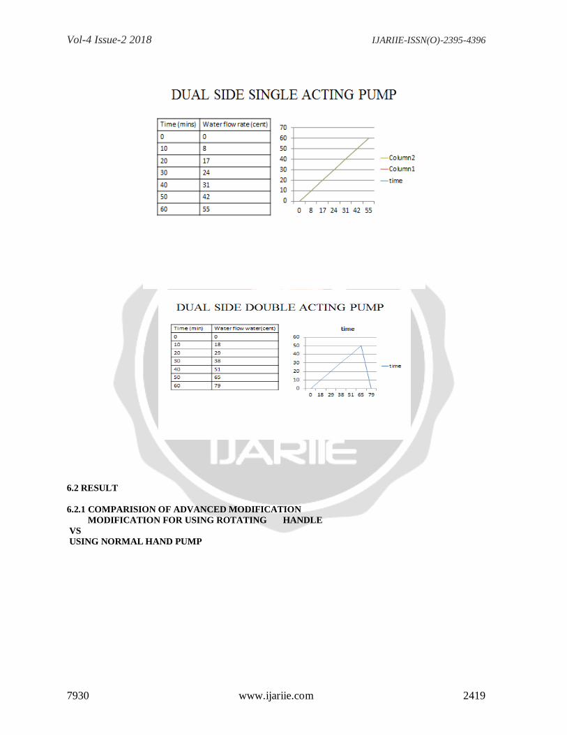
6.2 RESULT
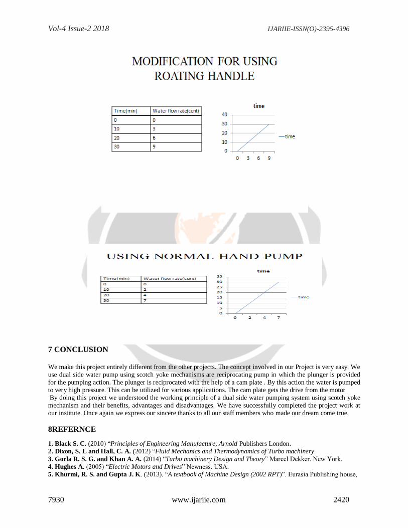
6.2.1 COMPARISION OF ADVANCED MODIFICATION
MODIFICATION FOR USING ROTATING HANDLE
VS
USING NORMAL HAND PUMP
Vol-4 Issue-2 2018 IJARIIE-ISSN(O)-2395-4396
7930 www.ijariie.com 2420
7 CONCLUSION
We make this project entirely different from the other projects. The concept involved in our Project is very easy. We
use dual side water pump using scotch yoke mechanisms are reciprocating pump in which the plunger is provided
for the pumping action. The plunger is reciprocated with the help of a cam plate . By this action the water is pumped
to very high pressure. This can be utilized for various applications. The cam plate gets the drive from the motor
By doing this project we understood the working principle of a dual side water pumping system using scotch yoke
mechanism and their benefits, advantages and disadvantages. We have successfully completed the project work at
our institute. Once again we express our sincere thanks to all our staff members who made our dream come true.
8REFERNCE
1. Black S. C. (2010) ―Principles of Engineering Manufacture, Arnold Publishers London.
2. Dixon, S. L and Hall, C. A. (2012) ―Fluid Mechanics and Thermodynamics of Turbo machinery
3. Gorla R. S. G. and Khan A. A. (2014) ―Turbo machinery Design and Theory‖ Marcel Dekker. New York.
4. Hughes A. (2005) ―Electric Motors and Drives‖ Newness. USA.
5. Khurmi, R. S. and Gupta J. K. (2013). ―A textbook of Machine Design (2002 RPT)‖. Eurasia Publishing house,
Vol-4 Issue-2 2018 IJARIIE-ISSN(O)-2395-4396
7930 www.ijariie.com 2421
New Delhi.
6. Kumar, K. L.(2016) ‖Engineering Fluid Mechanics‖. S. Chand and Company Ltd. New Delhi.
7. Sharma, P.C.(2015) ―A Textbook of Production Engineering‖. S. Chand and Company Ltd. New Delhi.
8. Tuzson J.(2014) ―Centrifugal Pump Design‖ John Wiley and Sons. New Jersey, United States.s