Embed Size (px)
Citation preview
Vol-4 Issue-2 2018 IJARIIE-ISSN(O)-2395-4396
7948 www.ijariie.com 2947
EFFICIENT DUAL AXIS SOLAR
TRACKER WITH H-BRIDGE INVERTER Avinash R*, Gowtham E*, Hemalatha s**
*UG student, EEE, Prince Shri Venkateshwara Padmavathy Engineering College, Tamil Nadu, India
**Assistant professor, EEE, Prince Shri Venkateshwara Padmavathy Engineering College, Tamil
Nadu, India
ABSTRACT
This paper concerns the design and realization of a solar tracking system oriented to the PV
conversion panels.The proposed dual axis solar tracking system offers optimal energy conversion process of
solar energy into electricity through appropriately orienting the PV panel in accordance with the real position
of the sun. The mechanism of the experiment is based on a servo motor which is intelligently controlled by
Arduino micro controller that moves prototype according to the inputs received from RTC clock.This project proposes a new single-phase H-Bridge transformerless inverter with common ground for grid connected
photovoltaic systems (hereafter it is called ‘Siwakoti-H’ inverter). The inverter works on the principle of flying
capacitor and consists of only four power switches (two reverse blocking IGBT’s (RB-IGBT) and two
MOSFET’s), a capacitor and a small filter at the output stage.
Keywords: Siwakoti Inverter, Arduino, RTC, Dual Axis Solar Tracker, Servo Motor
I. INTRODUCTION
Global warming and energy policies have become a hot topic on the international agenda in the last
years. Developed countries are trying to reduce their greenhouse gas emissions. For example, the EU has
committed to reduce the emissions of greenhouse gas to at least 20% below 1990 levels and to produce no less
than 20% of its energy consumption from renewable sources by 2020. In this context, photovoltaic (PV)power
generation has an important role to play due to the fact that it is a green source.
In their lifetime, which is around 25years, PV panels produce more energy than that for their
manufacturing. Also they can be installed in places with no other use, such as roofs and deserts, or they can
produce electricity for remote locations, where there is no electricity network. The latter type of installations is
known as off-grid facilities and sometimes they are the most economical alternative to provide electricity in
isolated areas. However, most of the PV power generation comes from grid-connected installations, where the
power is fed in the electricity network.
In this project a dual axis solar tracker system by having a servo motor which is intelligently controlled
by Arduino micro controller that moves prototype according to the inputs received from RTC clock. A new
single-phase H-Bridge transformer less inverter with common ground for grid connected photovoltaic systems
(hereafter it is called ‘Siwakoti-H’ inverter). In below content consist of the construction, operation, advantages
and disadvantages of a dual axis solar tracker and H-bridge Siwakoti inverter. Finally, simulation result of a
Siwakoti inverter and the conclusion are drawn in last section
POWER GENERATION IN SOLAR PANEL
Solar photo voltaic system uses solar cells to convert light into electricity. A PV system consists of PV
modules. Solar radiation is sufficient to generate required electricity. To run the elevator efficiently.The
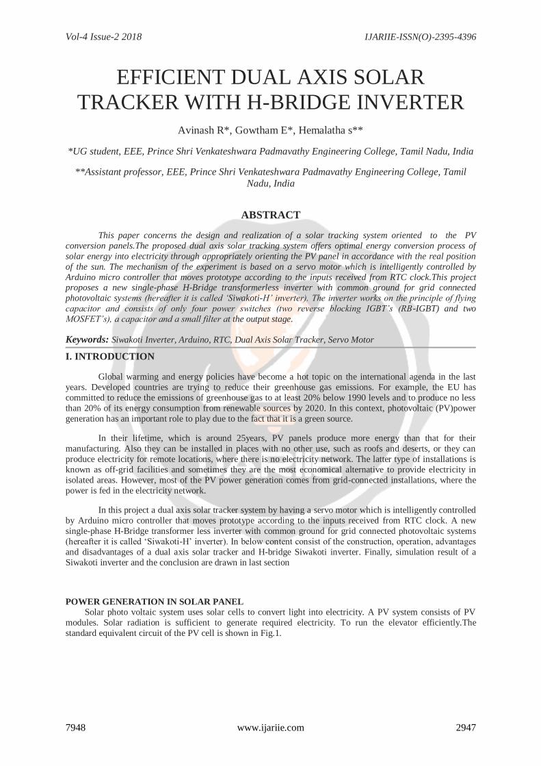
standard equivalent circuit of the PV cell is shown in Fig.1.
Vol-4 Issue-2 2018 IJARIIE-ISSN(O)-2395-4396
7948 www.ijariie.com 2948
Fig 1.1power generation in solar panel
The basic equation that describes the I-V Characteristics of the PV model is given by the following
equation:
𝐼 = 𝐼𝐿 − 𝐼𝑂 𝑒𝑞 𝑣+𝐼𝑅𝑠
𝐾𝑇 − 1 −𝑣 + 𝐼𝑅𝑠
𝑅𝑠ℎ
Where:
I - Cell Current (A).
IL - Light Generated Current (A).
Io - Diode Saturation Current.
Q - Charge of Electron = 1.6x10⁻¹⁹(Coul).
K - Boltzmann Constant (J/K)
V - Cell Output Voltage (V)
Rs , Rsh - Cell Series and Shunt Resistance(Ohms).
In this tracking methodology servo motor is intelligently controlled by Arduino micro controller that moves
prototype according to the inputs received from LDR sensor. The motor drive is used to give a sufficient input
supply for servo motor operation.
The required output from the PV panel is given to a 12V regulator for a constant supply of 12V power
to the battery. From the battery the power is distributed to siwakoti inverter, driver circuit and pulse generating
unit. Siwakoti inverter has two MOSFT and RB-IGBT in order to give a external pulse a pulse generating unit is
used. The obtained pulse from the pulse generating unit is not required to operate the MOSFET and IGBT so a
driver circuit is included in the circuit.
II. PROPOSED SYSTEM The solar tracking methodology is based on a servo motor which is intelligently controlled by Arduino
micro controller that moves prototype according to the inputs received from LDR sensors.
Vol-4 Issue-2 2018 IJARIIE-ISSN(O)-2395-4396
7948 www.ijariie.com 2949
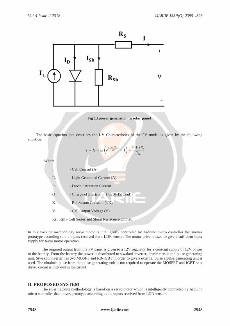
Fig.2 Block diagram
REAL TIME CLOCK (RTC)
A real-time clock is a computer clock (most often in form of an integrated circuit) that keeps track of
the current time.In our system RTC is used to give the input signal to Arduino. The solar panel is tilted
according to the time period fed into the Arduino. The solar panel’s first axis starts the tilting process from the east to west direction as of the sun’s direction. According to India for first six months sun will appear at one
corner and it gradually moves to next corner. Then for the next six months sun will appear on another corner. So
the time period for the other axis will be changed for every six months.
ARDUINO MICRO CONTROLLER
The signal from the LDR sensor is given as the input to the Arduino micro controller. This micro controller
as the prototype based on the input signal from the sensor and it gives the signal to the servo motor
SERVO MOTOR
Servo motor is used as the tilting medium in this tracking system. The servo motor has controlled by an intelligent controller called an Arduino controller. This controller feed with a prototype language by the signal
from the LDR sensor.
SIWAKOTI INVERTER
A new single-phase H-Bridge transformerless inverter with common ground for grid connected photovoltaic systems (hereafter it is called ‘Siwakoti-H’ inverter). The inverter works on the principle of flying
capacitor and consists of only four power switches (two reverse blocking IGBT’s (RB-IGBT) and two
MOSFET’s), a capacitor and a small filter at the output stage. The proposed topology share a common ground
with the grid and the PV source. A Unipolar Sinusoidal Pulse- Width Modulation (SPWM) technique is used to
modulate the inverter to minimize switching loss, output current ripple and filter requirements. The main
advantages of the new inverter topology are the elimination of the leakage current and ability to provide reactive
power to the grid. Further, the peak of output ac voltage is equal to input dcvoltage (unlike NPC and ANPC type
which requires two times of the peak ac-voltage magnitude). Simulation as well as experimental results from a 1
kW prototype are presented at the end of the paper to prove the concept and also the theoretical analysis
presented.
Vol-4 Issue-2 2018 IJARIIE-ISSN(O)-2395-4396
7948 www.ijariie.com 2950
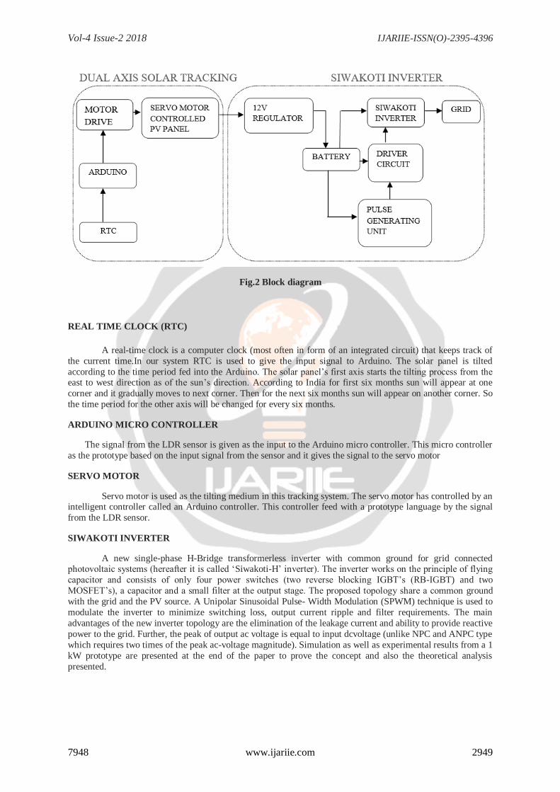
Fig.3 siwakoti inverter
III. WORKING AND MODES OF OPERATION
OPERATION MODES
STATES S1 S2 S3 S4
Positive
(Active)
0 0 1 0
Zero 1 0 0 1
Negative
(Active)
0 1 0 0
POSITIVE CYCLE
The positive modulating signal is compared with a triangular waveform to create the correct switching pulse for the switch S3, which creates unipolar positive voltage at the filter. Switches S1 and S4 are off during this state;
while, S2 also remains off for the whole positive cycle.
Fig.4 positive cycle
Vol-4 Issue-2 2018 IJARIIE-ISSN(O)-2395-4396
7948 www.ijariie.com 2951
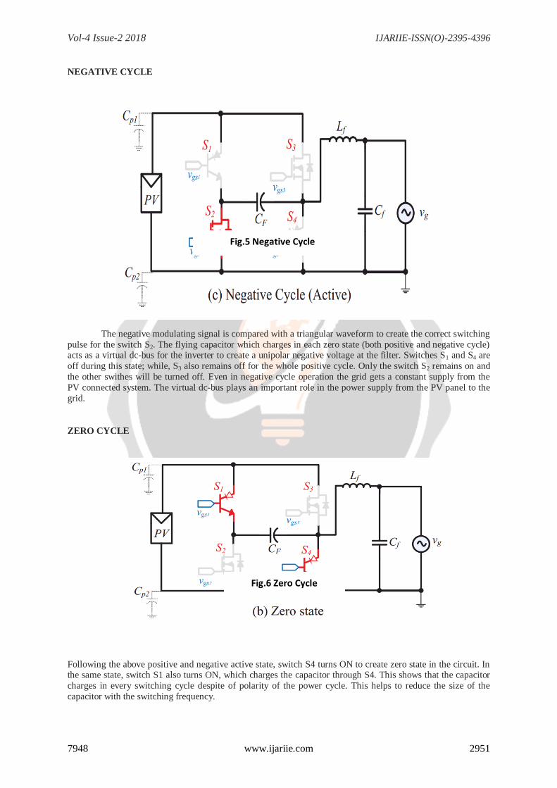
NEGATIVE CYCLE
The negative modulating signal is compared with a triangular waveform to create the correct switching
pulse for the switch S2. The flying capacitor which charges in each zero state (both positive and negative cycle) acts as a virtual dc-bus for the inverter to create a unipolar negative voltage at the filter. Switches S1 and S4 are
off during this state; while, S3 also remains off for the whole positive cycle. Only the switch S2 remains on and
the other swithes will be turned off. Even in negative cycle operation the grid gets a constant supply from the
PV connected system. The virtual dc-bus plays an important role in the power supply from the PV panel to the
grid.
ZERO CYCLE
Following the above positive and negative active state, switch S4 turns ON to create zero state in the circuit. In the same state, switch S1 also turns ON, which charges the capacitor through S4. This shows that the capacitor
charges in every switching cycle despite of polarity of the power cycle. This helps to reduce the size of the
capacitor with the switching frequency.
Fig.5 Negative Cycle
Fig.6 Zero Cycle
Vol-4 Issue-2 2018 IJARIIE-ISSN(O)-2395-4396
7948 www.ijariie.com 2952
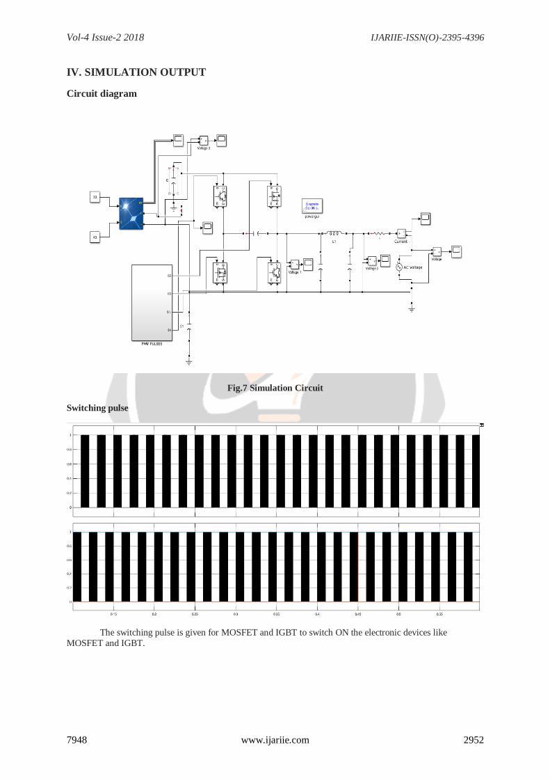
IV. SIMULATION OUTPUT
Circuit diagram
Fig.7 Simulation Circuit
Switching pulse
The switching pulse is given for MOSFET and IGBT to switch ON the electronic devices like
MOSFET and IGBT.
Vol-4 Issue-2 2018 IJARIIE-ISSN(O)-2395-4396
7948 www.ijariie.com 2953
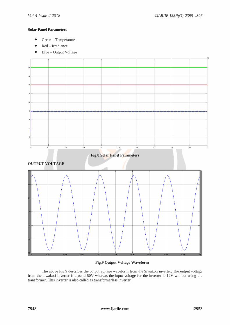
Solar Panel Parameters
Green – Temperature
Red – Irradiance
Blue – Output Voltage
Fig.8 Solar Panel Parameters
OUTPUT VOLTAGE
Fig.9 Output Voltage Waveform
The above Fig.9 describes the output voltage waveform from the Siwakoti inverter. The output voltage from the siwakoti inverter is around 50V whereas the input voltage for the inverter is 12V without using the
transformer. This inverter is also called as transformerless inverter.
OUTPUT VOLTAGE
OUTPUT VOLTAGE
Vol-4 Issue-2 2018 IJARIIE-ISSN(O)-2395-4396
7948 www.ijariie.com 2954
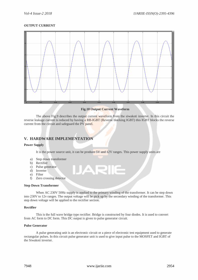
OUTPUT CURRENT
Fig.10 Output Current Waveform
The above Fig.9 describes the output current waveform from the siwakoti inverter. In this circuit the
reverse leakage current is reduced by having a RB-IGBT (Reverse blocking IGBT) this IGBT blocks the reverse
current from the circuit and safeguard the PV panel.
V. HARDWARE IMPLEMENTATION
Power Supply
It is the power source unit, it can be produce 5V and 12V ranges. This power supply units are
a) Step down transformer
b) Rectifier
c) Pulse generator
d) Inverter
e) Filter f) Zero crossing detector
Step Down Transformer
When AC 230V 50Hz supply is applied to the primary winding of the transformer. It can be step down
into 230V to 12v ranges. The output voltage will be pick up by the secondary winding of the transformer. This step down voltage will be applied to the rectifier section.
Rectifier
This is the full wave bridge type rectifier. Bridge is constructed by four diodes. It is used to convert from AC form to DC form. This DC output is given to pulse generator circuit.
Pulse Generator
A pulse generating unit is an electronic circuit or a piece of electronic test equipment used to generate
rectangular pulses. In this circuit pulse generator unit is used to give input pulse to the MOSFET and IGBT of the Siwakoti inverter.
Vol-4 Issue-2 2018 IJARIIE-ISSN(O)-2395-4396
7948 www.ijariie.com 2955
Inverter
Inverter is the circuit which is used to convert DC supply to AC supply. In this circuit the DC output from the solar panel is converted to AC supply by having a H-Bridge Siwakoti inverter.
Filter
Filter used in this circuit is LC filter which is used to reduce the ripples from the output voltage of
Siwakoti inverter.
Zero crossing detector
A zero crossing detector or ZCD is a one type of voltage comparator, used to detect a sine waveform
transition from positive and negative, that coincides when the input crosses the zero voltage condition.
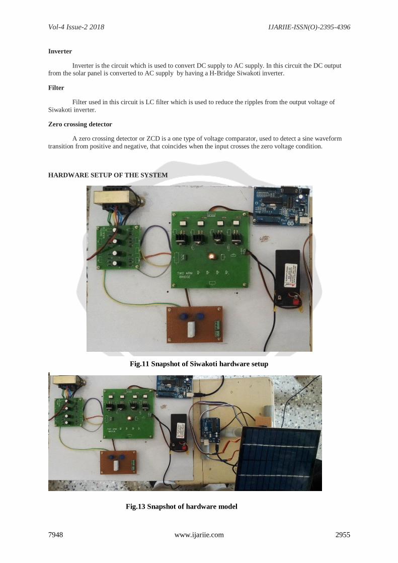
HARDWARE SETUP OF THE SYSTEM
Fig.11 Snapshot of Siwakoti hardware setup
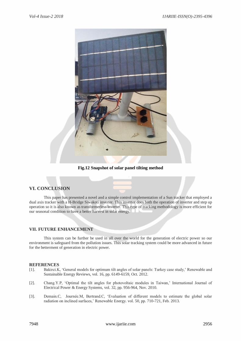
Fig.13 Snapshot of hardware model
Vol-4 Issue-2 2018 IJARIIE-ISSN(O)-2395-4396
7948 www.ijariie.com 2956
VI. CONCLUSION
This paper has presented a novel and a simple control implementation of a Sun tracker that employed a
dual axis tracker with a H-Bridge Siwakoti inverter. This inverter does both the operation of inverter and step up
operation so it is also known as transformerless inverter. This type of tracking methodology is more efficient for
our seasonal condition to have a better harvest in solar energy.
VII. FUTURE ENHANCEMENT
This system can be further be used in all over the world for the generation of electric power so our
environment is safeguard from the pollution issues. This solar tracking system could be more advanced in future
for the betterment of generation in electric power.
REFERENCES [1]. Bakirci.K, ‘General models for optimum tilt angles of solar panels: Turkey case study,’ Renewable and
Sustainable Energy Reviews, vol. 16, pp. 6149-6159, Oct. 2012.
[2]. Chang.Y.P, ‘Optimal the tilt angles for photovoltaic modules in Taiwan,’ International Journal of
Electrical Power & Energy Systems, vol. 32, pp. 956-964, Nov. 2010.
[3]. Demain.C, Journée.M, Bertrand.C, ‘Evaluation of different models to estimate the global solar
radiation on inclined surfaces,’ Renewable Energy. vol. 50, pp. 710-721, Feb. 2013.
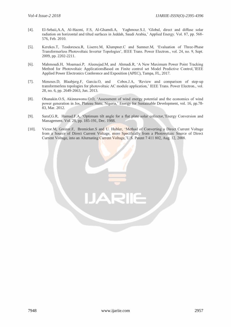
Fig.12 Snapshot of solar panel tilting method
Vol-4 Issue-2 2018 IJARIIE-ISSN(O)-2395-4396
7948 www.ijariie.com 2957
[4]. El-Sebaii,A.A, Al-Hazmi, F.S, Al-Ghamdi.A, Yaghmour.S.J, ‘Global, direct and diffuse solar
radiation on horizontal and tilted surfaces in Jeddah, Saudi Arabia,’ Applied Energy. Vol. 87, pp. 568-
576, Feb. 2010.
[5]. Kerekes.T, Teodorescu.R, Liserre.M, Klumpner.C and Sumner.M, ‘Evaluation of Three-Phase
Transformerless Photovoltaic Inverter Topologies’, IEEE Trans. Power Electron., vol. 24, no. 9, Sept.
2009, pp. 2202-2211.
[6]. Mahmoudi.H, Moamaei.P, Aleenejad.M, and Ahmadi.R, ‘A New Maximum Power Point Tracking
Method for Photovoltaic ApplicationsBased on Finite control set Model Predictive Control,’IEEE
Applied Power Electronics Conference and Exposition (APEC), Tampa, FL, 2017.
[7]. Meneses.D, Blaabjerg.F, Garcia.O, and Cobos.J.A, ‘Review and comparison of step-up
transformerless topologies for photovoltaic AC module application,’ IEEE Trans. Power Electron., vol.
28, no. 6, pp. 2649-2663, Jun. 2013.
[8]. Ohunakin.O.S, Akinnawonu.O.O, ‘Assessment of wind energy potential and the economics of wind
power generation in Jos, Plateau State, Nigeria,’ Energy for Sustainable Development, vol. 16, pp.78-83, Mar. 2012.
[9]. Saraf,G.R, Hamad.F.A, ‘Optimum tilt angle for a flat plate solar collector,’Energy Conversion and
Management. Vol. 28, pp. 185-191, Dec. 1988.
[10]. Victor.M, Greizer.F, Bremicker.S and U. Hubler, ‘Method of Converting a Direct Current Voltage from a Source of Direct Current Voltage, more Specifically from a Photovoltaic Source of Direct
Current Voltage, into an Alternating Current Voltage,’U.S. Patent 7 411 802, Aug. 12, 2008.


![“CFD ANALYSIS HELICAL COIL HEAT EXCHANGER”ijariie.com/AdminUploadPdf/CFD_ANALYSIS_HELICAL_COIL_HEAT_E… · Shinde Digvijay D. et al. [3] studied the experimental investigation](https://img.pdfslide.us/doc/110x75/5fa1c8c0022f2e4c0b162c6a/aoecfd-analysis-helical-coil-heat-exchangera-shinde-digvijay-d-et-al-3-studied.jpg)
