Embed Size (px)
Citation preview
Dual 137.5-4400MHz Frequency
Synthesizer Programmable Modules
A. Mattana, M. Schiaffino
IRA 484/14
Istituto di Radio Astronomia, Bologna, INAF

2
Referee: Germano Bianchi
Index
3
Index
Index
THE AIM OF THE PROJECT ........................................................................................................................................... 5
INTRO ............................................................................................................................................................................... 5
THE SYNTHESIZER MODULE ........................................................................................................................................ 6
5007 VALON TECHNOLOGY LLC DATA SHEET ........................................................................................................................... 6
5007 BLOCK DIAGRAM ........................................................................................................................................................ 8
5007 DIMENSIONS AND MOUNTING LOCATIONS ....................................................................................................................... 9
5007 CONNECTORS............................................................................................................................................................. 9
5007 TYPICAL PHASE NOISE ............................................................................................................................................... 10
5007 USER INTERFACE ...................................................................................................................................................... 11
MOXA NPORT IA-5150 ...............................................................................................................................................12
NPORT IA-5150 DATA SHEET............................................................................................................................................ 12
PRODUCT FEATURES .......................................................................................................................................................... 12
PRODUCT SPECIFICATIONS ................................................................................................................................................... 13
PANEL LAYOUT ................................................................................................................................................................. 14
OPERATION MODES ........................................................................................................................................................... 14
REAL COM MODE ............................................................................................................................................................ 15
TCP SERVER MODE ........................................................................................................................................................... 15
WEB CONSOLE CONFIGURATION .......................................................................................................................................... 16
NETWORK SETTINGS .......................................................................................................................................................... 17
SERIAL SETTINGS ............................................................................................................................................................... 18
OPERATING SETTINGS ........................................................................................................................................................ 19
BOXING TWO SYNTHESIZER MODULES ......................................................................................................................20
1U RACK MOUNTABLE ETHERNET CONTROLLED SYNTHESIZER .................................................................................................... 20
USB POCKET SYNTHESIZER .................................................................................................................................................. 22
NRAO LINUX PYTHON LIBRARY ..................................................................................................................................23
SOURCE CODE .................................................................................................................................................................. 23

Index
4
(This page has been intentionally left blank)
Intro
5
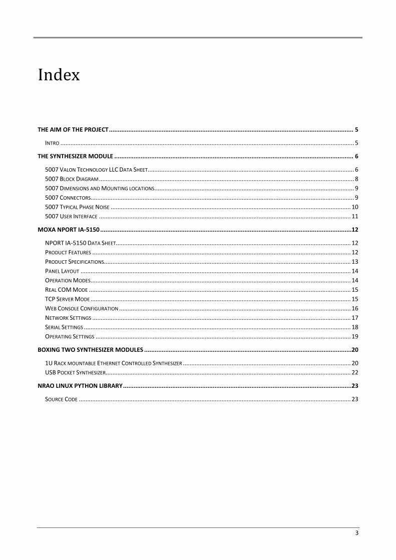
The aim of the project
Intro
Most of the data acquisition systems do not have their own stable clock to sample analog input signals but
provide input lines to connect external ultra-stable clock source. Usually an expensive signal generator is
used locked to ultra-stable 10MHz sine wave reference, but, the higher the frequency range the higher is
the cost, and, the higher the frequency the worst can be the phase noise when for budget reasons the
target must be a cheaper signal generator (sometimes refurbished).
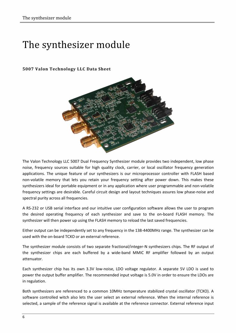
A very interesting module has been realized few years ago by the Valon Technology LLC and passed many
careful tests also done by the community of CASPER (https://casper.berkeley.edu/wiki/Main_Page). It is a
Dual 137.5-4400MHz Frequency Synthesizer mini board (about only 50x50mm) having low phase noise an
low power consumption and integrating a microcontroller and flash memory to program the desired
frequency to individual output and the possibility to use an external reference or an onboard oscillator.
The 5007 synthesizer module is sell unboxed (therefore unshielded) and needs an additional serial adapter
(that can be a 9-Pin DSUB connector interface or a mini USB adapter, both 3VTTL).
Several data acquisition boards used here at the Medicina Radiotelescopes station may use this synthesizer
if placed in the same rack of the backend and properly shielded. Due to the flexibility and scalability of the
Medicina backends that allow to load different projects over the same hardware there is the need to use
different clock frequencies to drive the ADC boards, and, if the frequency change can be done remotely and
loaded automatically by the same scripts which configure the backend project would be very useful.
The target can be easily reached by using a Ethernet-Serial adapter which allows to use serial devices over a
Ethernet link.
The synthesizer module
6
The synthesizer module
5007 Valon Technology LLC Data Sheet
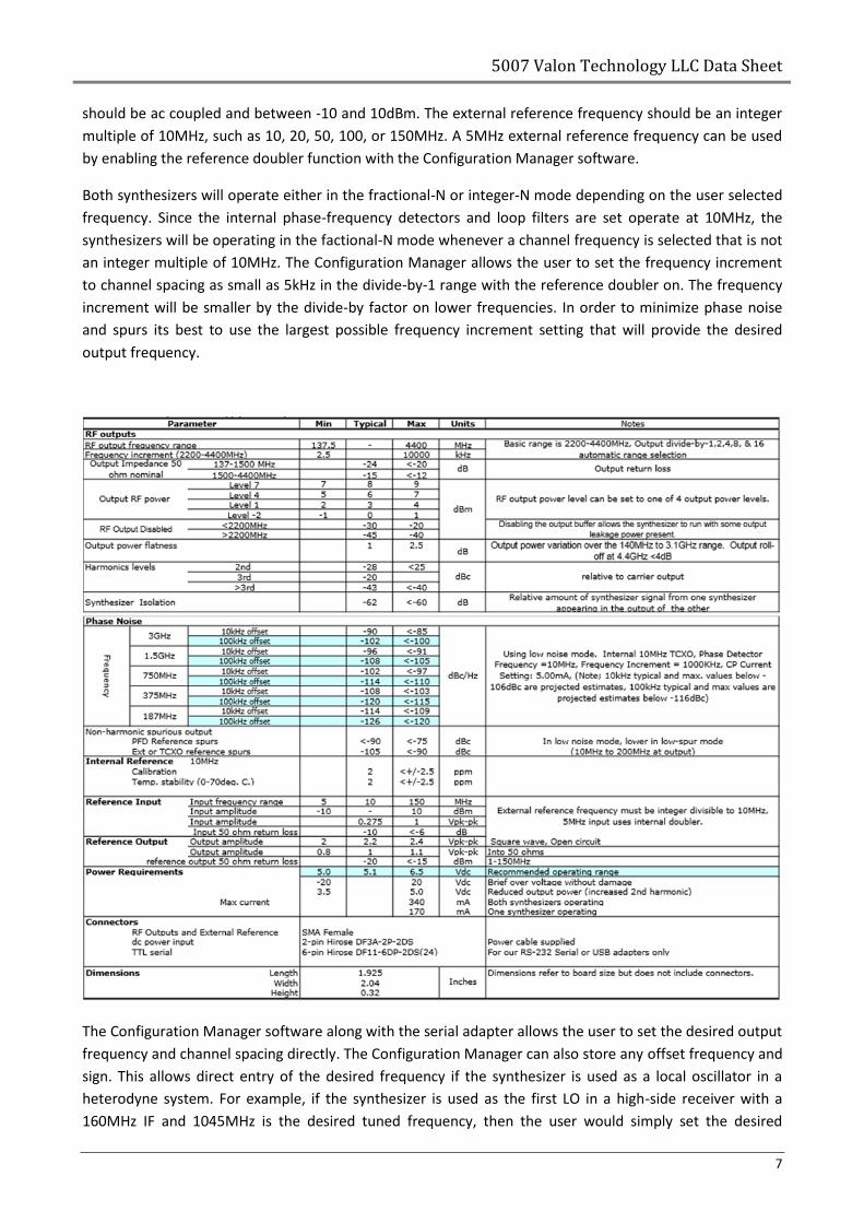
The Valon Technology LLC 5007 Dual Frequency Synthesizer module provides two independent, low phase
noise, frequency sources suitable for high quality clock, carrier, or local oscillator frequency generation
applications. The unique feature of our synthesizers is our microprocessor controller with FLASH based
non-volatile memory that lets you retain your frequency setting after power down. This makes these
synthesizers ideal for portable equipment or in any application where user programmable and non-volatile
frequency settings are desirable. Careful circuit design and layout techniques assures low phase-noise and
spectral purity across all frequencies.
A RS-232 or USB serial interface and our intuitive user configuration software allows the user to program
the desired operating frequency of each synthesizer and save to the on-board FLASH memory. The
synthesizer will then power up using the FLASH memory to reload the last saved frequencies.
Either output can be independently set to any frequency in the 138-4400MHz range. The synthesizer can be
used with the on-board TCXO or an external reference.
The synthesizer module consists of two separate fractional/integer-N synthesizers chips. The RF output of
the synthesizer chips are each buffered by a wide-band MMIC RF amplifier followed by an output
attenuator.
Each synthesizer chip has its own 3.3V low-noise, LDO voltage regulator. A separate 5V LDO is used to
power the output buffer amplifier. The recommended input voltage is 5.0V in order to ensure the LDOs are
in regulation.
Both synthesizers are referenced to a common 10MHz temperature stabilized crystal oscillator (TCXO). A
software controlled witch also lets the user select an external reference. When the internal reference is
selected, a sample of the reference signal is available at the reference connector. External reference input
5007 Valon Technology LLC Data Sheet
7
should be ac coupled and between -10 and 10dBm. The external reference frequency should be an integer
multiple of 10MHz, such as 10, 20, 50, 100, or 150MHz. A 5MHz external reference frequency can be used
by enabling the reference doubler function with the Configuration Manager software.
Both synthesizers will operate either in the fractional-N or integer-N mode depending on the user selected
frequency. Since the internal phase-frequency detectors and loop filters are set operate at 10MHz, the
synthesizers will be operating in the factional-N mode whenever a channel frequency is selected that is not
an integer multiple of 10MHz. The Configuration Manager allows the user to set the frequency increment
to channel spacing as small as 5kHz in the divide-by-1 range with the reference doubler on. The frequency
increment will be smaller by the divide-by factor on lower frequencies. In order to minimize phase noise
and spurs its best to use the largest possible frequency increment setting that will provide the desired
output frequency.
The Configuration Manager software along with the serial adapter allows the user to set the desired output
frequency and channel spacing directly. The Configuration Manager can also store any offset frequency and
sign. This allows direct entry of the desired frequency if the synthesizer is used as a local oscillator in a
heterodyne system. For example, if the synthesizer is used as the first LO in a high-side receiver with a
160MHz IF and 1045MHz is the desired tuned frequency, then the user would simply set the desired
The synthesizer module
8
frequency to 1045MHz and the offset to 160MHz. The Configuration Manager calculates the correct LO
output frequency.
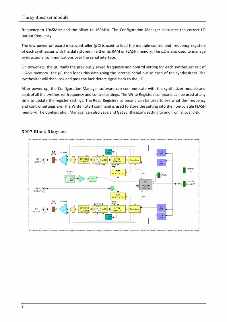
The low-power on-board microcontroller (µC) is used to load the multiple control and frequency registers
of each synthesizer with the data stored in either its RAM or FLASH memory. The µC is also used to manage
bi-directional communications over the serial interface.
On power-up, the µC reads the previously saved frequency and control setting for each synthesizer out of
FLASH memory. The µC then loads this data using the internal serial bus to each of the synthesizers. The
synthesizer will then lock and pass the lock detect signal back to the µC.
After power-up, the Configuration Manager software can communicate with the synthesizer module and
control all the synthesizer frequency and control settings. The Write Registers command can be used at any
time to update the register settings. The Read Registers command can be used to see what the frequency
and control settings are. The Write FLASH command is used to store the setting into the non-volatile FLASH
memory. The Configuration Manager can also Save and Get synthesizer's setting to and from a local disk.
5007 Block Diagram
5007 Dimensions and Mounting locations
9
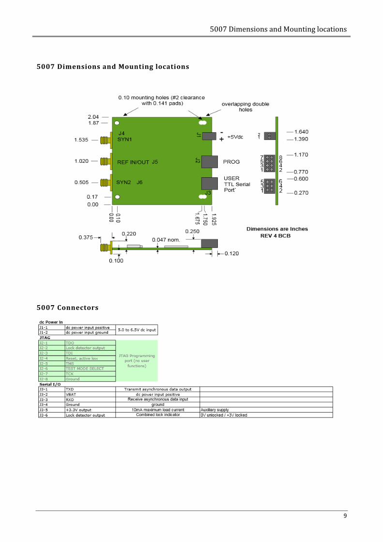
5007 Dimensions and Mounting locations
5007 Connectors
The synthesizer module
10
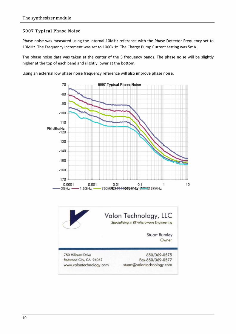
5007 Typical Phase Noise
Phase noise was measured using the internal 10MHz reference with the Phase Detector Frequency set to
10MHz. The Frequency Increment was set to 1000kHz. The Charge Pump Current setting was 5mA.
The phase noise data was taken at the center of the 5 frequency bands. The phase noise will be slightly
higher at the top of each band and slightly lower at the bottom.
Using an external low phase noise frequency reference will also improve phase noise.
5007 User Interface
11
5007 User Interface
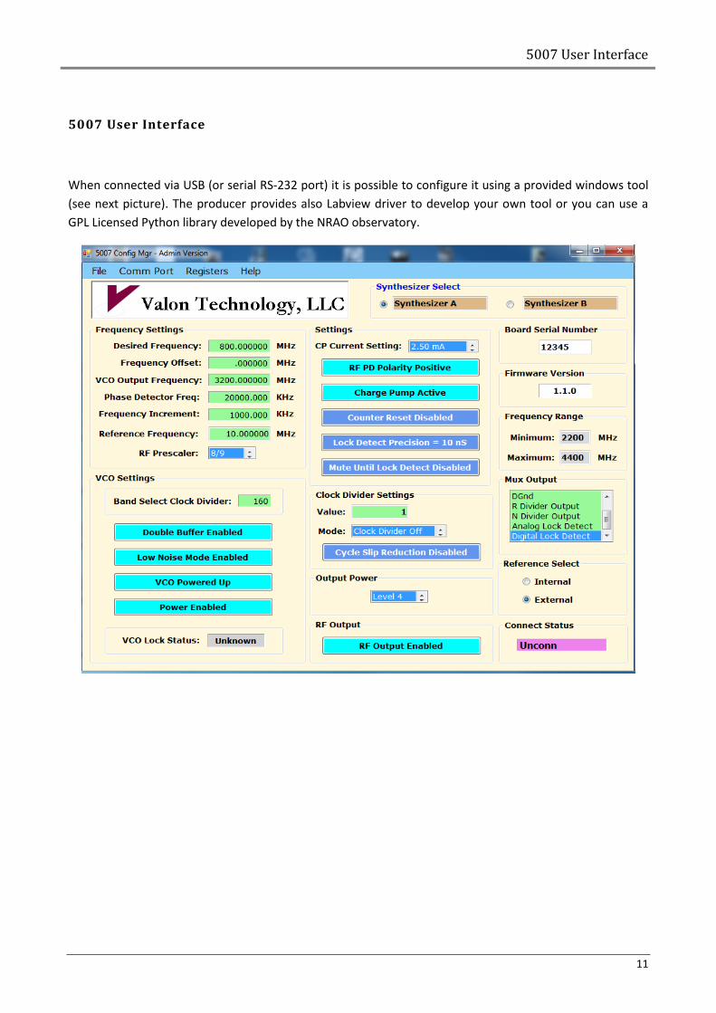
When connected via USB (or serial RS-232 port) it is possible to configure it using a provided windows tool
(see next picture). The producer provides also Labview driver to develop your own tool or you can use a
GPL Licensed Python library developed by the NRAO observatory.
Moxa NPORT IA-5150
12
Moxa NPORT IA-5150
NPORT IA-5150 Data Sheet
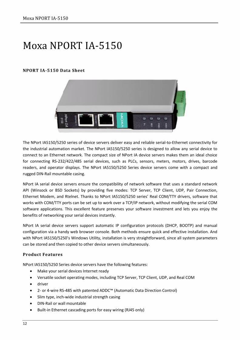
The NPort IA5150/5250 series of device servers deliver easy and reliable serial-to-Ethernet connectivity for
the industrial automation market. The NPort IA5150/5250 series is designed to allow any serial device to
connect to an Ethernet network. The compact size of NPort IA device servers makes them an ideal choice
for connecting RS-232/422/485 serial devices, such as PLCs, sensors, meters, motors, drives, barcode
readers, and operator displays. The NPort IA5150/5250 Series device servers come with a compact and
rugged DIN-Rail mountable casing.
NPort IA serial device servers ensure the compatibility of network software that uses a standard network
API (Winsock or BSD Sockets) by providing five modes: TCP Server, TCP Client, UDP, Pair Connection,
Ethernet Modem, and Rtelnet. Thanks to NPort IA5150/5250 series’ Real COM/TTY drivers, software that
works with COM/TTY ports can be set up to work over a TCP/IP network, without modifying the serial COM
software applications. This excellent feature preserves your software investment and lets you enjoy the
benefits of networking your serial devices instantly.
NPort IA serial device servers support automatic IP configuration protocols (DHCP, BOOTP) and manual
configuration via a handy web browser console. Both methods ensure quick and effective installation. And
with NPort IA5150/5250’s Windows Utility, installation is very straightforward, since all system parameters
can be stored and then copied to other device servers simultaneously.
Product Features
NPort IA5150/5250 Series device servers have the following features:
Make your serial devices Internet ready
Versatile socket operating modes, including TCP Server, TCP Client, UDP, and Real COM
driver
2- or 4-wire RS-485 with patented ADDC™ (Automatic Data Direction Control)
Slim type, inch-wide industrial strength casing
DIN-Rail or wall mountable
Built-in Ethernet cascading ports for easy wiring (RJ45 only)
Product Specifications
13
Redundant dual DC power inputs
Warning by relay output and E-mail
10/100BaseTX (RJ45) or 100BaseFX (SC connector, Single/Multi mode) available
IP30
Product Specifications
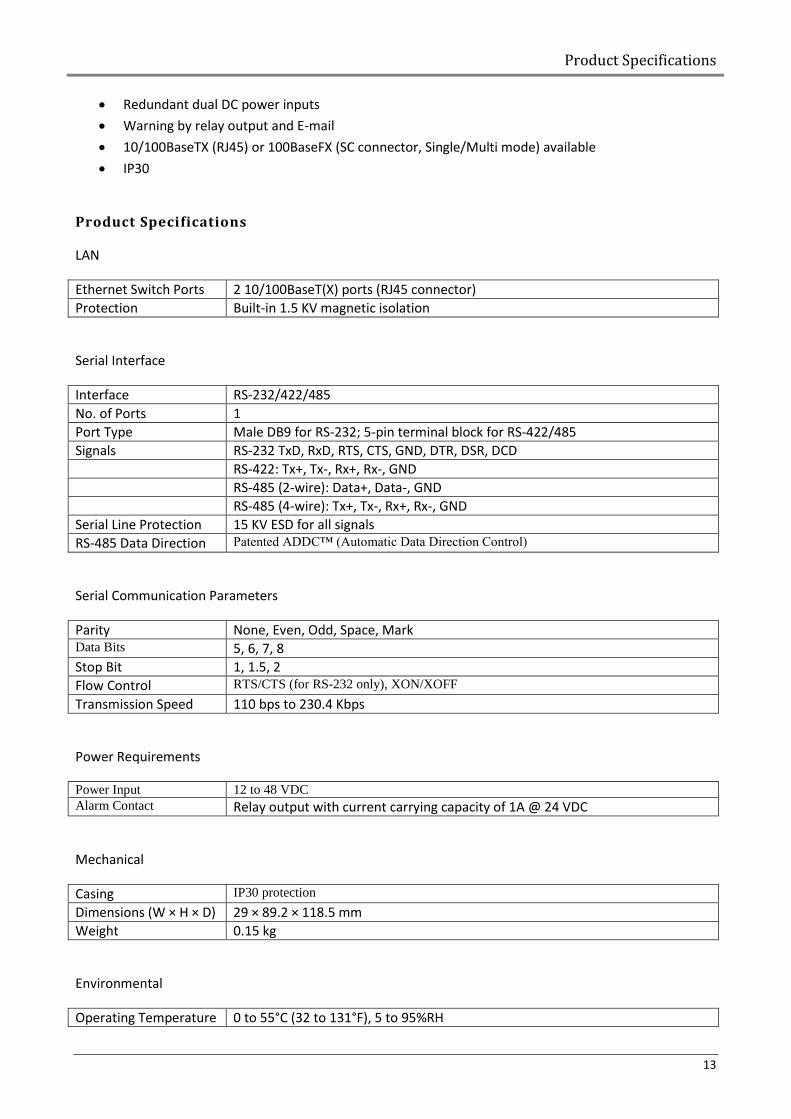
LAN
Ethernet Switch Ports 2 10/100BaseT(X) ports (RJ45 connector)
Protection Built-in 1.5 KV magnetic isolation
Serial Interface
Interface RS-232/422/485
No. of Ports 1
Port Type Male DB9 for RS-232; 5-pin terminal block for RS-422/485
Signals RS-232 TxD, RxD, RTS, CTS, GND, DTR, DSR, DCD
RS-422: Tx+, Tx-, Rx+, Rx-, GND
RS-485 (2-wire): Data+, Data-, GND
RS-485 (4-wire): Tx+, Tx-, Rx+, Rx-, GND
Serial Line Protection 15 KV ESD for all signals
RS-485 Data Direction Patented ADDC™ (Automatic Data Direction Control)
Serial Communication Parameters
Parity None, Even, Odd, Space, Mark Data Bits 5, 6, 7, 8
Stop Bit 1, 1.5, 2
Flow Control RTS/CTS (for RS-232 only), XON/XOFF
Transmission Speed 110 bps to 230.4 Kbps
Power Requirements
Power Input 12 to 48 VDC
Alarm Contact Relay output with current carrying capacity of 1A @ 24 VDC
Mechanical
Casing IP30 protection
Dimensions (W × H × D) 29 × 89.2 × 118.5 mm
Weight 0.15 kg
Environmental
Operating Temperature 0 to 55°C (32 to 131°F), 5 to 95%RH
Moxa NPORT IA-5150
14
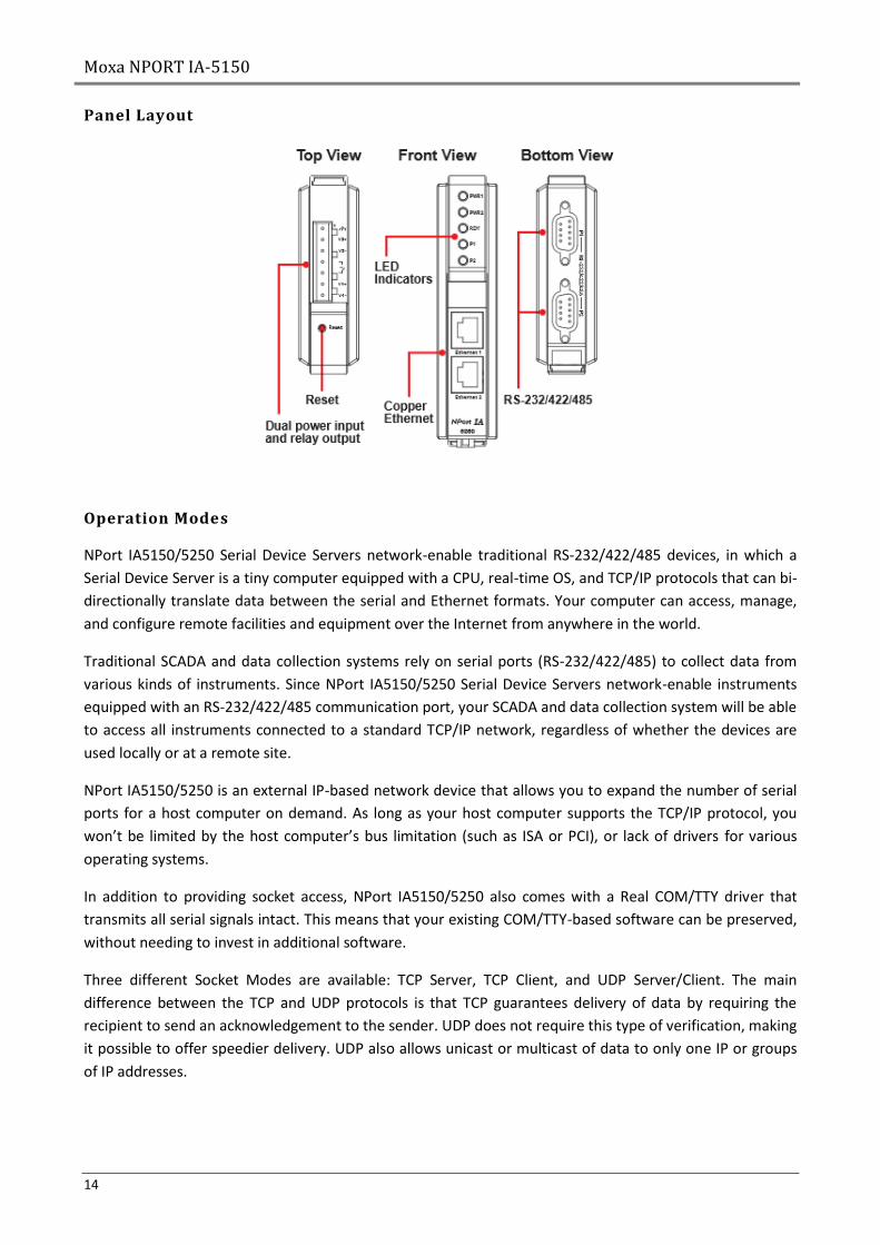
Panel Layout
Operation Modes
NPort IA5150/5250 Serial Device Servers network-enable traditional RS-232/422/485 devices, in which a
Serial Device Server is a tiny computer equipped with a CPU, real-time OS, and TCP/IP protocols that can bi-
directionally translate data between the serial and Ethernet formats. Your computer can access, manage,
and configure remote facilities and equipment over the Internet from anywhere in the world.
Traditional SCADA and data collection systems rely on serial ports (RS-232/422/485) to collect data from
various kinds of instruments. Since NPort IA5150/5250 Serial Device Servers network-enable instruments
equipped with an RS-232/422/485 communication port, your SCADA and data collection system will be able
to access all instruments connected to a standard TCP/IP network, regardless of whether the devices are
used locally or at a remote site.
NPort IA5150/5250 is an external IP-based network device that allows you to expand the number of serial
ports for a host computer on demand. As long as your host computer supports the TCP/IP protocol, you
won’t be limited by the host computer’s bus limitation (such as ISA or PCI), or lack of drivers for various
operating systems.
In addition to providing socket access, NPort IA5150/5250 also comes with a Real COM/TTY driver that
transmits all serial signals intact. This means that your existing COM/TTY-based software can be preserved,
without needing to invest in additional software.
Three different Socket Modes are available: TCP Server, TCP Client, and UDP Server/Client. The main
difference between the TCP and UDP protocols is that TCP guarantees delivery of data by requiring the
recipient to send an acknowledgement to the sender. UDP does not require this type of verification, making
it possible to offer speedier delivery. UDP also allows unicast or multicast of data to only one IP or groups
of IP addresses.
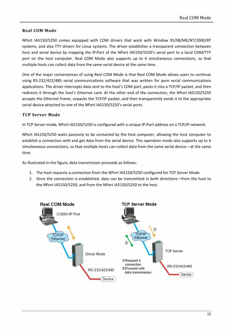
Real COM Mode
15
Real COM Mode
NPort IA5150/5250 comes equipped with COM drivers that work with Window 95/98/ME/NT/2000/XP
systems, and also TTY drivers for Linux systems. The driver establishes a transparent connection between
host and serial device by mapping the IP:Port of the NPort IA5150/5250’s serial port to a local COM/TTY
port on the host computer. Real COM Mode also supports up to 4 simultaneous connections, so that
multiple hosts can collect data from the same serial device at the same time.
One of the major conveniences of using Real COM Mode is that Real COM Mode allows users to continue
using RS-232/422/485 serial communications software that was written for pure serial communications
applications. The driver intercepts data sent to the host’s COM port, packs it into a TCP/IP packet, and then
redirects it through the host’s Ethernet card. At the other end of the connection, the NPort IA5150/5250
accepts the Ethernet frame, unpacks the TCP/IP packet, and then transparently sends it to the appropriate
serial device attached to one of the NPort IA5150/5250’s serial ports.
TCP Server Mode
In TCP Server mode, NPort IA5150/5250 is configured with a unique IP:Port address on a TCP/IP network.
NPort IA5150/5250 waits passively to be contacted by the host computer, allowing the host computer to
establish a connection with and get data from the serial device. This operation mode also supports up to 4
simultaneous connections, so that multiple hosts can collect data from the same serial device—at the same
time.
As illustrated in the figure, data transmission proceeds as follows:
1. The host requests a connection from the NPort IA5150/5250 configured for TCP Server Mode.
2. Once the connection is established, data can be transmitted in both directions—from the host to
the NPort IA5150/5250, and from the NPort IA5150/5250 to the host.
Moxa NPORT IA-5150
16
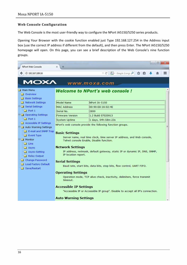
Web Console Configuration
The Web Console is the most user-friendly way to configure the NPort IA5150/5250 series products.
Opening Your Browser with the cookie function enabled just Type 192.168.127.254 in the Address input
box (use the correct IP address if different from the default), and then press Enter. The NPort IA5150/5250
homepage will open. On this page, you can see a brief description of the Web Console’s nine function
groups.
Network Settings
17
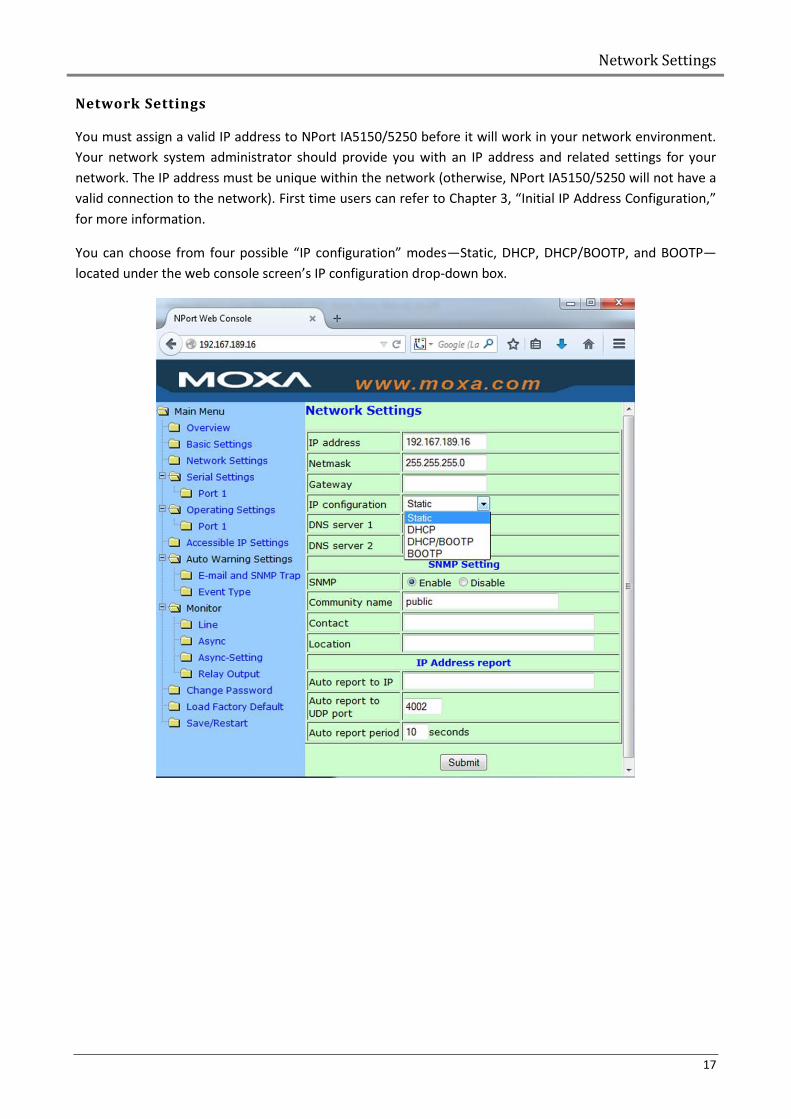
Network Settings
You must assign a valid IP address to NPort IA5150/5250 before it will work in your network environment.
Your network system administrator should provide you with an IP address and related settings for your
network. The IP address must be unique within the network (otherwise, NPort IA5150/5250 will not have a
valid connection to the network). First time users can refer to Chapter 3, “Initial IP Address Configuration,”
for more information.
You can choose from four possible “IP configuration” modes—Static, DHCP, DHCP/BOOTP, and BOOTP—
located under the web console screen’s IP configuration drop-down box.
Moxa NPORT IA-5150
18
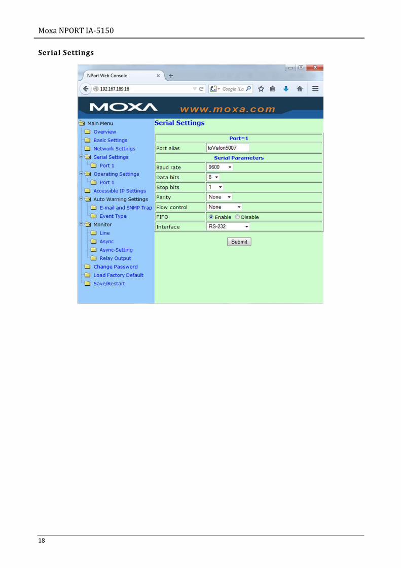
Serial Settings
Operating Settings
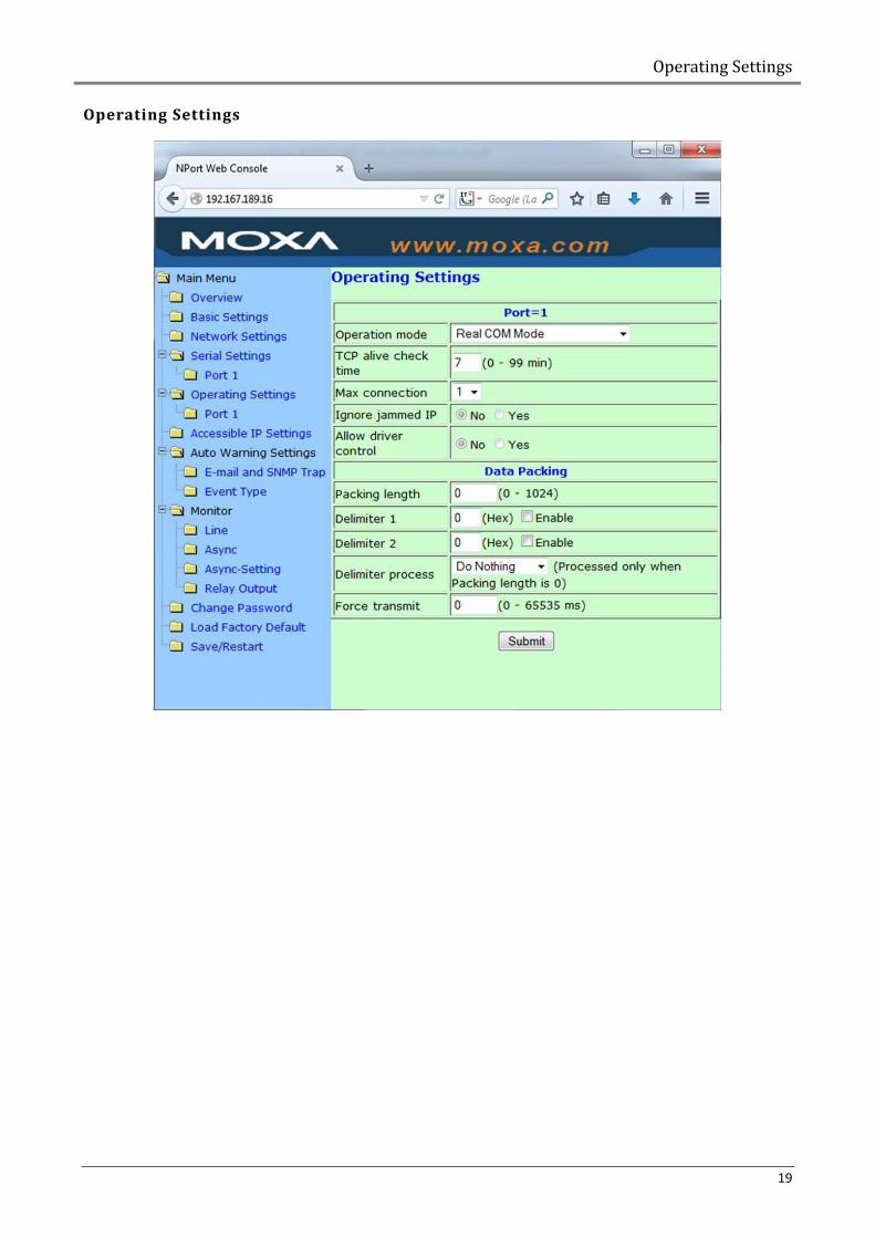
19
Operating Settings
Boxing Two Synthesizer modules
20
Boxing Two Synthesizer modules
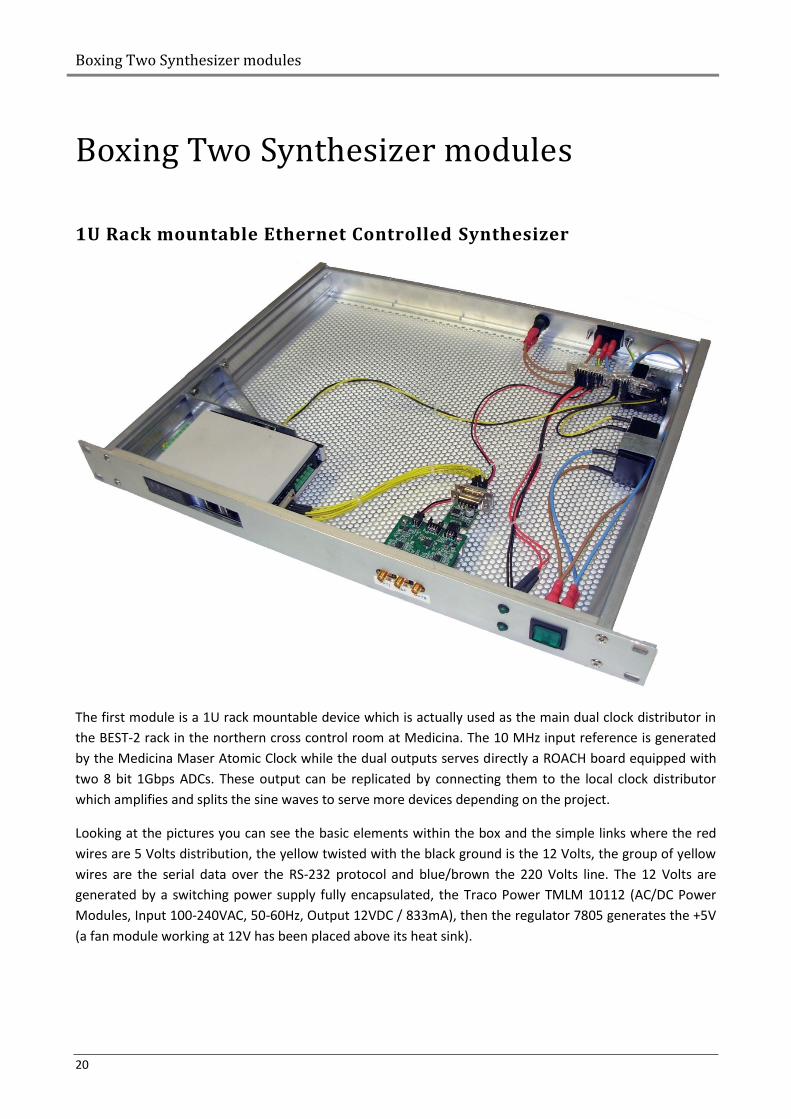
1U Rack mountable Ethernet Controlled Synthesizer
The first module is a 1U rack mountable device which is actually used as the main dual clock distributor in
the BEST-2 rack in the northern cross control room at Medicina. The 10 MHz input reference is generated
by the Medicina Maser Atomic Clock while the dual outputs serves directly a ROACH board equipped with
two 8 bit 1Gbps ADCs. These output can be replicated by connecting them to the local clock distributor
which amplifies and splits the sine waves to serve more devices depending on the project.
Looking at the pictures you can see the basic elements within the box and the simple links where the red
wires are 5 Volts distribution, the yellow twisted with the black ground is the 12 Volts, the group of yellow
wires are the serial data over the RS-232 protocol and blue/brown the 220 Volts line. The 12 Volts are
generated by a switching power supply fully encapsulated, the Traco Power TMLM 10112 (AC/DC Power
Modules, Input 100-240VAC, 50-60Hz, Output 12VDC / 833mA), then the regulator 7805 generates the +5V
(a fan module working at 12V has been placed above its heat sink).
1U Rack mountable Ethernet Controlled Synthesizer
21
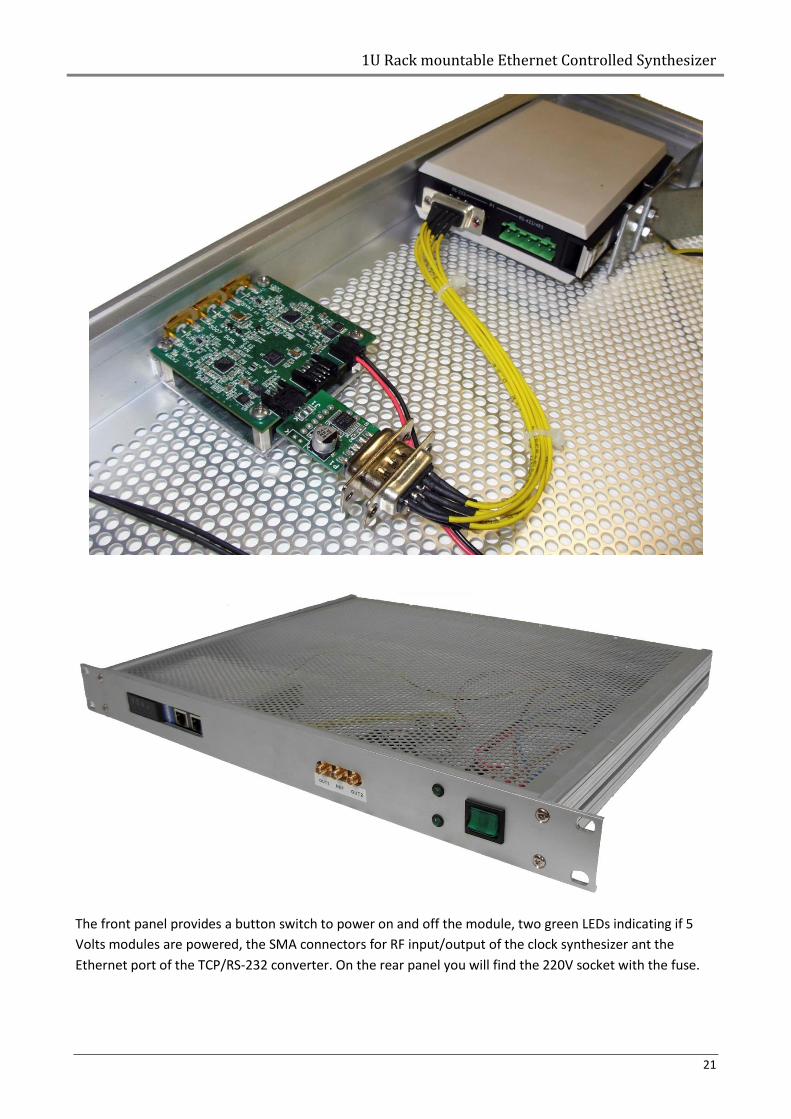
The front panel provides a button switch to power on and off the module, two green LEDs indicating if 5
Volts modules are powered, the SMA connectors for RF input/output of the clock synthesizer ant the
Ethernet port of the TCP/RS-232 converter. On the rear panel you will find the 220V socket with the fuse.
Boxing Two Synthesizer modules
22
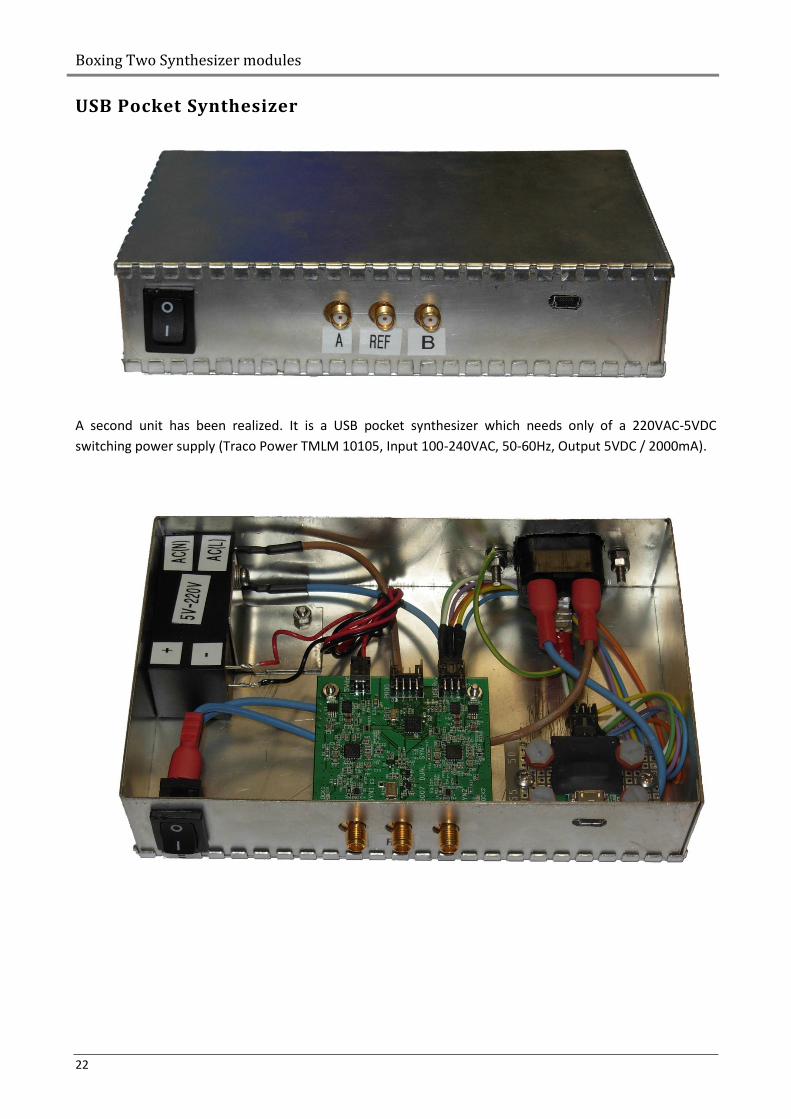
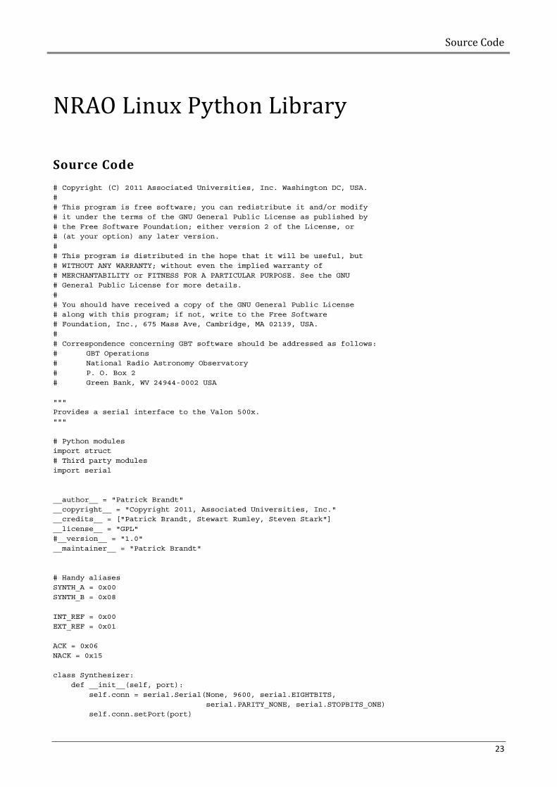
USB Pocket Synthesizer
A second unit has been realized. It is a USB pocket synthesizer which needs only of a 220VAC-5VDC
switching power supply (Traco Power TMLM 10105, Input 100-240VAC, 50-60Hz, Output 5VDC / 2000mA).
Source Code
23
NRAO Linux Python Library
Source Code
# Copyright (C) 2011 Associated Universities, Inc. Washington DC, USA.
#
# This program is free software; you can redistribute it and/or modify
# it under the terms of the GNU General Public License as published by
# the Free Software Foundation; either version 2 of the License, or
# (at your option) any later version.
#
# This program is distributed in the hope that it will be useful, but
# WITHOUT ANY WARRANTY; without even the implied warranty of
# MERCHANTABILITY or FITNESS FOR A PARTICULAR PURPOSE. See the GNU
# General Public License for more details.
#
# You should have received a copy of the GNU General Public License
# along with this program; if not, write to the Free Software
# Foundation, Inc., 675 Mass Ave, Cambridge, MA 02139, USA.
#
# Correspondence concerning GBT software should be addressed as follows:
# GBT Operations
# National Radio Astronomy Observatory
# P. O. Box 2
# Green Bank, WV 24944-0002 USA
"""
Provides a serial interface to the Valon 500x.
"""
# Python modules
import struct
# Third party modules
import serial
__author__ = "Patrick Brandt"
__copyright__ = "Copyright 2011, Associated Universities, Inc."
__credits__ = ["Patrick Brandt, Stewart Rumley, Steven Stark"]
__license__ = "GPL"
#__version__ = "1.0"
__maintainer__ = "Patrick Brandt"
# Handy aliases
SYNTH_A = 0x00
SYNTH_B = 0x08
INT_REF = 0x00
EXT_REF = 0x01
ACK = 0x06
NACK = 0x15
class Synthesizer:
def __init__(self, port):
self.conn = serial.Serial(None, 9600, serial.EIGHTBITS,
serial.PARITY_NONE, serial.STOPBITS_ONE)
self.conn.setPort(port)
NRAO Linux Python Library
24
def _generate_checksum(self, bytes):
return chr(sum([ord(b) for b in bytes]) % 256)
def _verify_checksum(self, bytes, checksum):
return (self._generate_checksum(bytes) == checksum)
def _pack_freq_registers(self, ncount, frac, mod, dbf, old_bytes):
dbf_table = {1: 0, 2: 1, 4: 2, 8: 3, 16: 4}
reg0, reg1, reg2, reg3, reg4, reg5 = struct.unpack('>IIIIII', old_bytes)
reg0 &= 0x80000007
reg0 |= ((ncount & 0xffff) << 15) | ((frac & 0x0fff) << 3)
reg1 &= 0xffff8007
reg1 |= (mod & 0x0fff) << 3
reg4 &= 0xff8fffff
reg4 |= (dbf_table.get(dbf, 0)) << 20
return struct.pack('>IIIIII', reg0, reg1, reg2, reg3, reg4, reg5)
def _unpack_freq_registers(self, bytes):
dbf_rev_table = {0: 1, 1: 2, 2: 4, 3: 8, 4: 16}
reg0, reg1, reg2, reg3, reg4, reg5 = struct.unpack('>IIIIII', bytes)
ncount = (reg0 >> 15) & 0xffff
frac = (reg0 >> 3) & 0x0fff
mod = (reg1 >> 3) & 0x0fff
dbf = dbf_rev_table.get((reg4 >> 20) & 0x07, 1)
return ncount, frac, mod, dbf
def get_frequency(self, synth):
"""
Returns the current output frequency for the selected synthesizer.
@param synth : synthesizer this command affects (0 for 1, 8 for 2).
@type synth : int
@return: the frequency in MHz (float)
"""
self.conn.open()
bytes = struct.pack('>B', 0x80 | synth)
self.conn.write(bytes)
bytes = self.conn.read(24)
checksum = self.conn.read(1)
self.conn.close()
#self._verify_checksum(bytes, checksum)
ncount, frac, mod, dbf = self._unpack_freq_registers(bytes)
EPDF = self._getEPDF(synth)
return (ncount + float(frac) / mod) * EPDF / dbf
def set_frequency(self, synth, freq, chan_spacing = 10.):
"""
Sets the synthesizer to the desired frequency
Sets to the closest possible frequency, depending on the channel spacing.
Range is determined by the minimum and maximum VCO frequency.
@param synth : synthesizer this command affects (0 for 1, 8 for 2).
@type synth : int
@param freq : output frequency
@type freq : float
@param chan_spacing : output frequency increment
@type chan_spacing : float
@return: True if success (bool)
"""
min, max = self.get_vco_range(synth)
dbf = 1
while (freq * dbf) <= min and dbf <= 16:
dbf *= 2
Source Code
25
if dbf > 16:
dbf = 16
vco = freq * dbf
EPDF = self._getEPDF(synth)
ncount = int(vco / EPDF)
frac = int((vco - ncount * float(EPDF)) / chan_spacing + 0.5)
mod = int(EPDF / float(chan_spacing) + 0.5)
if frac != 0 and mod != 0:
while not (frac & 1) and not (mod & 1):
frac /= 2
mod /= 2
else:
frac = 0
mod = 1
self.conn.open()
bytes = struct.pack('>B', 0x80 | synth)
self.conn.write(bytes)
old_bytes = self.conn.read(24)
checksum = self.conn.read(1)
#self._verify_checksum(old_bytes, checksum)
bytes = struct.pack('>B24s', 0x00 | synth,
self._pack_freq_registers(ncount, frac, mod,
dbf, old_bytes))
checksum = self._generate_checksum(bytes)
self.conn.write(bytes + checksum)
bytes = self.conn.read(1)
self.conn.close()
ack = struct.unpack('>B', bytes)[0]
return ack == ACK
def get_reference(self):
"""
Get reference frequency in MHz
"""
self.conn.open()
bytes = struct.pack('>B', 0x81)
self.conn.write(bytes)
bytes = self.conn.read(4)
checksum = self.conn.read(1)
self.conn.close()
#self._verify_checksum(bytes, checksum)
freq = struct.unpack('>I', bytes)[0]
return freq
def set_reference(self, freq):
"""
Set reference frequency in MHz
@param freq : frequency in MHz
@type freq : float
@return: True if success (bool)
"""
self.conn.open()
bytes = struct.pack('>BI', 0x01, freq)
checksum = self._generate_checksum(bytes)
self.conn.write(bytes + checksum)
bytes = self.conn.read(1)
self.conn.close()
ack = struct.unpack('>B', bytes)[0]
return ack == ACK
def get_rf_level(self, synth):
"""
Returns RF level in dBm
@param synth : synthesizer address, 0 or 8
@type synth : int
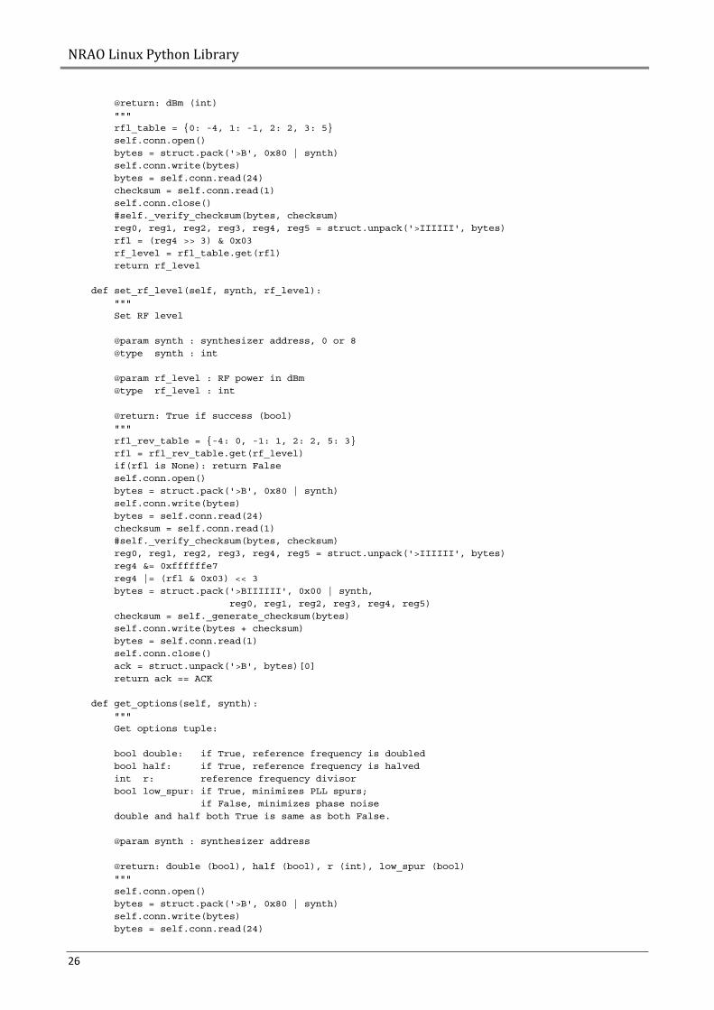
NRAO Linux Python Library
26
@return: dBm (int)
"""
rfl_table = {0: -4, 1: -1, 2: 2, 3: 5}
self.conn.open()
bytes = struct.pack('>B', 0x80 | synth)
self.conn.write(bytes)
bytes = self.conn.read(24)
checksum = self.conn.read(1)
self.conn.close()
#self._verify_checksum(bytes, checksum)
reg0, reg1, reg2, reg3, reg4, reg5 = struct.unpack('>IIIIII', bytes)
rfl = (reg4 >> 3) & 0x03
rf_level = rfl_table.get(rfl)
return rf_level
def set_rf_level(self, synth, rf_level):
"""
Set RF level
@param synth : synthesizer address, 0 or 8
@type synth : int
@param rf_level : RF power in dBm
@type rf_level : int
@return: True if success (bool)
"""
rfl_rev_table = {-4: 0, -1: 1, 2: 2, 5: 3}
rfl = rfl_rev_table.get(rf_level)
if(rfl is None): return False
self.conn.open()
bytes = struct.pack('>B', 0x80 | synth)
self.conn.write(bytes)
bytes = self.conn.read(24)
checksum = self.conn.read(1)
#self._verify_checksum(bytes, checksum)
reg0, reg1, reg2, reg3, reg4, reg5 = struct.unpack('>IIIIII', bytes)
reg4 &= 0xffffffe7
reg4 |= (rfl & 0x03) << 3
bytes = struct.pack('>BIIIIII', 0x00 | synth,
reg0, reg1, reg2, reg3, reg4, reg5)
checksum = self._generate_checksum(bytes)
self.conn.write(bytes + checksum)
bytes = self.conn.read(1)
self.conn.close()
ack = struct.unpack('>B', bytes)[0]
return ack == ACK
def get_options(self, synth):
"""
Get options tuple:
bool double: if True, reference frequency is doubled
bool half: if True, reference frequency is halved
int r: reference frequency divisor
bool low_spur: if True, minimizes PLL spurs;
if False, minimizes phase noise
double and half both True is same as both False.
@param synth : synthesizer address
@return: double (bool), half (bool), r (int), low_spur (bool)
"""
self.conn.open()
bytes = struct.pack('>B', 0x80 | synth)
self.conn.write(bytes)
bytes = self.conn.read(24)
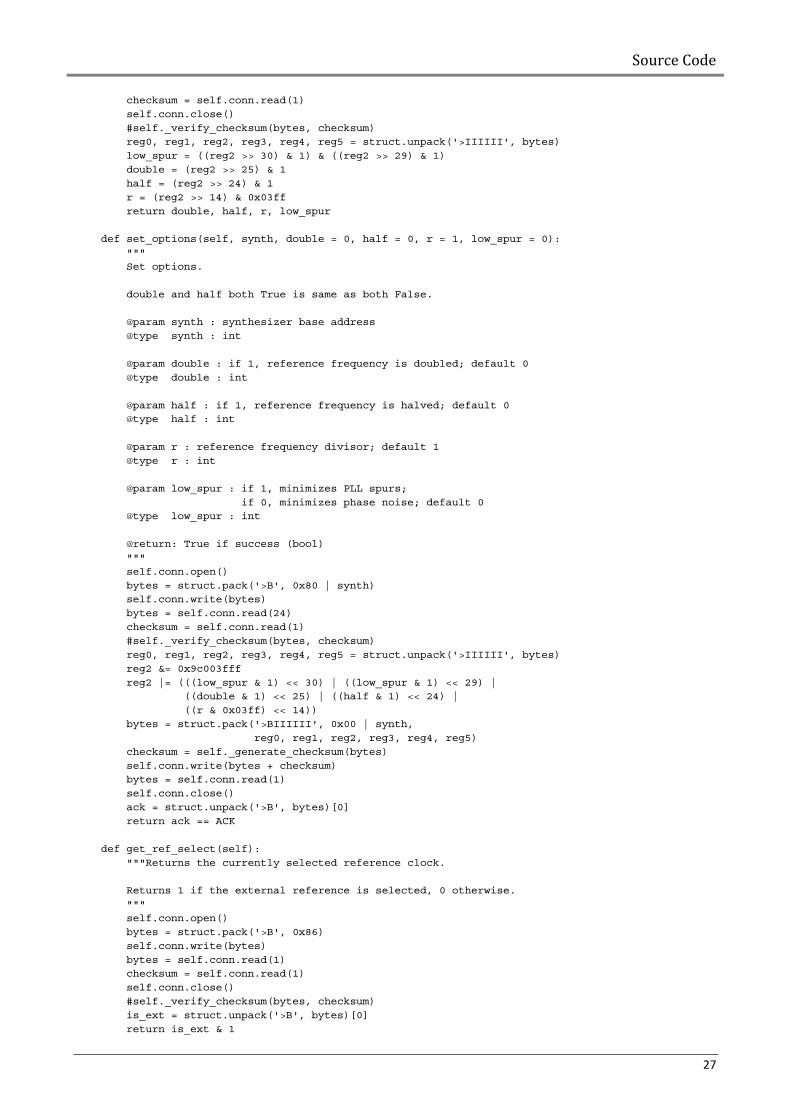
Source Code
27
checksum = self.conn.read(1)
self.conn.close()
#self._verify_checksum(bytes, checksum)
reg0, reg1, reg2, reg3, reg4, reg5 = struct.unpack('>IIIIII', bytes)
low_spur = ((reg2 >> 30) & 1) & ((reg2 >> 29) & 1)
double = (reg2 >> 25) & 1
half = (reg2 >> 24) & 1
r = (reg2 >> 14) & 0x03ff
return double, half, r, low_spur
def set_options(self, synth, double = 0, half = 0, r = 1, low_spur = 0):
"""
Set options.
double and half both True is same as both False.
@param synth : synthesizer base address
@type synth : int
@param double : if 1, reference frequency is doubled; default 0
@type double : int
@param half : if 1, reference frequency is halved; default 0
@type half : int
@param r : reference frequency divisor; default 1
@type r : int
@param low_spur : if 1, minimizes PLL spurs;
if 0, minimizes phase noise; default 0
@type low_spur : int
@return: True if success (bool)
"""
self.conn.open()
bytes = struct.pack('>B', 0x80 | synth)
self.conn.write(bytes)
bytes = self.conn.read(24)
checksum = self.conn.read(1)
#self._verify_checksum(bytes, checksum)
reg0, reg1, reg2, reg3, reg4, reg5 = struct.unpack('>IIIIII', bytes)
reg2 &= 0x9c003fff
reg2 |= (((low_spur & 1) << 30) | ((low_spur & 1) << 29) |
((double & 1) << 25) | ((half & 1) << 24) |
((r & 0x03ff) << 14))
bytes = struct.pack('>BIIIIII', 0x00 | synth,
reg0, reg1, reg2, reg3, reg4, reg5)
checksum = self._generate_checksum(bytes)
self.conn.write(bytes + checksum)
bytes = self.conn.read(1)
self.conn.close()
ack = struct.unpack('>B', bytes)[0]
return ack == ACK
def get_ref_select(self):
"""Returns the currently selected reference clock.
Returns 1 if the external reference is selected, 0 otherwise.
"""
self.conn.open()
bytes = struct.pack('>B', 0x86)
self.conn.write(bytes)
bytes = self.conn.read(1)
checksum = self.conn.read(1)
self.conn.close()
#self._verify_checksum(bytes, checksum)
is_ext = struct.unpack('>B', bytes)[0]
return is_ext & 1
NRAO Linux Python Library
28
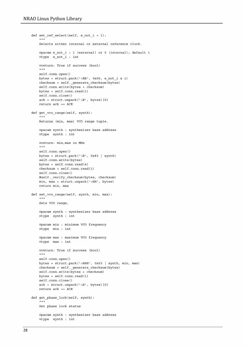
def set_ref_select(self, e_not_i = 1):
"""
Selects either internal or external reference clock.
@param e_not_i : 1 (external) or 0 (internal); default 1
@type e_not_i : int
@return: True if success (bool)
"""
self.conn.open()
bytes = struct.pack('>BB', 0x06, e_not_i & 1)
checksum = self._generate_checksum(bytes)
self.conn.write(bytes + checksum)
bytes = self.conn.read(1)
self.conn.close()
ack = struct.unpack('>B', bytes)[0]
return ack == ACK
def get_vco_range(self, synth):
"""
Returns (min, max) VCO range tuple.
@param synth : synthesizer base address
@type synth : int
@return: min,max in MHz
"""
self.conn.open()
bytes = struct.pack('>B', 0x83 | synth)
self.conn.write(bytes)
bytes = self.conn.read(4)
checksum = self.conn.read(1)
self.conn.close()
#self._verify_checksum(bytes, checksum)
min, max = struct.unpack('>HH', bytes)
return min, max
def set_vco_range(self, synth, min, max):
"""
Sets VCO range.
@param synth : synthesizer base address
@type synth : int
@param min : minimum VCO frequency
@type min : int
@param max : maximum VCO frequency
@type max : int
@return: True if success (bool)
"""
self.conn.open()
bytes = struct.pack('>BHH', 0x03 | synth, min, max)
checksum = self._generate_checksum(bytes)
self.conn.write(bytes + checksum)
bytes = self.conn.read(1)
self.conn.close()
ack = struct.unpack('>B', bytes)[0]
return ack == ACK
def get_phase_lock(self, synth):
"""
Get phase lock status
@param synth : synthesizer base address
@type synth : int
Source Code
29
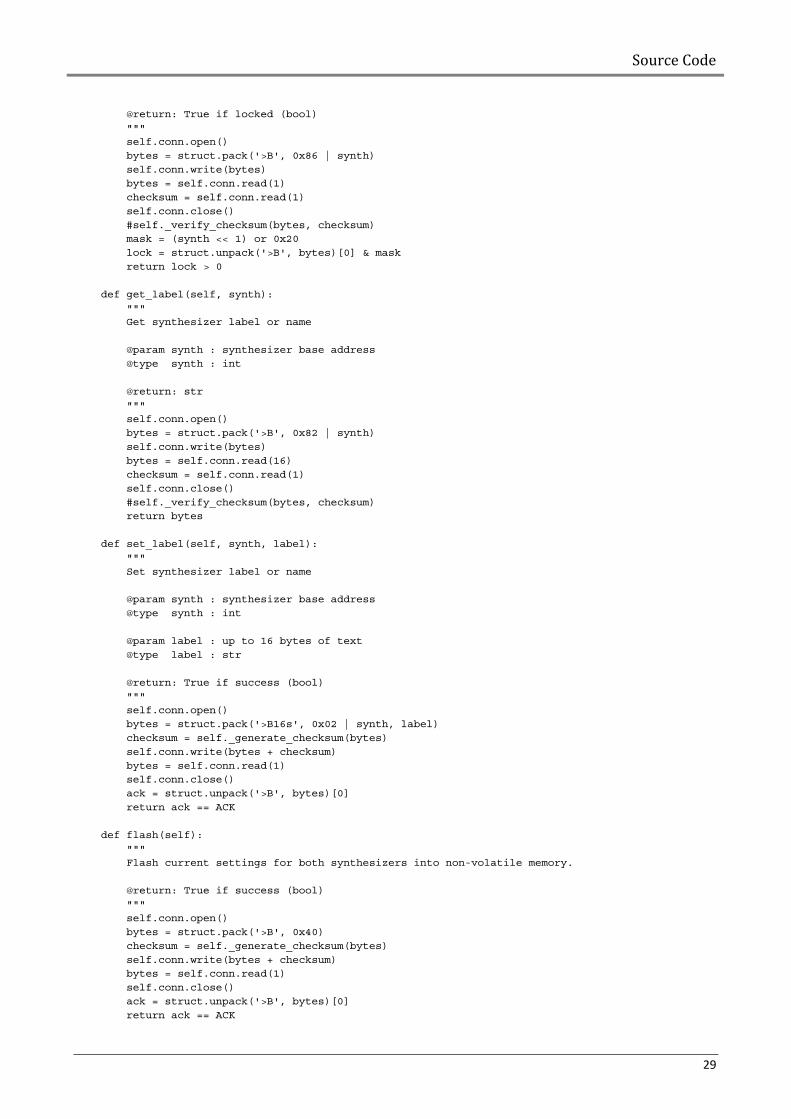
@return: True if locked (bool)
"""
self.conn.open()
bytes = struct.pack('>B', 0x86 | synth)
self.conn.write(bytes)
bytes = self.conn.read(1)
checksum = self.conn.read(1)
self.conn.close()
#self._verify_checksum(bytes, checksum)
mask = (synth << 1) or 0x20
lock = struct.unpack('>B', bytes)[0] & mask
return lock > 0
def get_label(self, synth):
"""
Get synthesizer label or name
@param synth : synthesizer base address
@type synth : int
@return: str
"""
self.conn.open()
bytes = struct.pack('>B', 0x82 | synth)
self.conn.write(bytes)
bytes = self.conn.read(16)
checksum = self.conn.read(1)
self.conn.close()
#self._verify_checksum(bytes, checksum)
return bytes
def set_label(self, synth, label):
"""
Set synthesizer label or name
@param synth : synthesizer base address
@type synth : int
@param label : up to 16 bytes of text
@type label : str
@return: True if success (bool)
"""
self.conn.open()
bytes = struct.pack('>B16s', 0x02 | synth, label)
checksum = self._generate_checksum(bytes)
self.conn.write(bytes + checksum)
bytes = self.conn.read(1)
self.conn.close()
ack = struct.unpack('>B', bytes)[0]
return ack == ACK
def flash(self):
"""
Flash current settings for both synthesizers into non-volatile memory.
@return: True if success (bool)
"""
self.conn.open()
bytes = struct.pack('>B', 0x40)
checksum = self._generate_checksum(bytes)
self.conn.write(bytes + checksum)
bytes = self.conn.read(1)
self.conn.close()
ack = struct.unpack('>B', bytes)[0]
return ack == ACK
NRAO Linux Python Library
30
def _getEPDF(self, synth):
"""
Returns effective phase detector frequency.
This is the reference frequency with options applied.
"""
reference = self.get_reference() / 1e6
double, half, r, low_spur = self.get_options(synth)
if(double): reference *= 2.0
if(half): reference /= 2.0
if(r > 1): reference /= r
return reference