Embed Size (px)
Citation preview
40- CHANNEL CB -READY JAN. 1
THE MAGAZINE FOR NEW IDEAS IN ELECTRONICS
make with ICs DIGITAL CAR CLOCK put it anywhere
5 full octaves KEYBOARD SYNTHESIZER you can build
General Instrument IC DATA SHEET for video gam
how we check NOISE ME in hi -fi gear
all about ANALOG M for everyone
PLUS * More About TV G * Jack Darr's Servic * Step By S * Komputer * State Of S * Lab Teste
- es
1 Fury _... utAY
TO b39Y14S130ZMXM8
LL80 Y tii aMtyZOg S10 9GZ19G '
www.americanradiohistory.com
Remote ControJco Racer A
Computer logic has added a new fun way to control remote control products:
The Remote Control Racer is a competi- tion scale model race car controlled by a trans- mitter using computer logic.
Think of it. Remotely drive a model race car from as far as sixty feet-turning left and right, going forward and reverse. It's great fun for hobbiests, children and the whole family. DIGITALLY PROPORTIONAL CONTROL
The steering is controlled as you control the steering wheel on your remote control unit. Turn the wheel slightly to the right and the car wheels turn slightly to the right. Turn your control fully to the left and the car wheels turn fully to the left.
There is no transmission required to go from forward to reverse as the high quality servo motor simply reverses polarity to change gears. Press the forward lever on your remote unit and you go forward. Press the reverse le- ver and you go in reverse. It's just that quick.
BUILT TO THE FINEST DETAIL The camber caster -action front wheels par-
allel a full -sized car's suspension system and they actually tilt on the turns. An indepen- dent floating rear axle maintains positive trac- tion even on rough terrain.
The Remote Racer replaces the gasoline powered remote control race cars that have
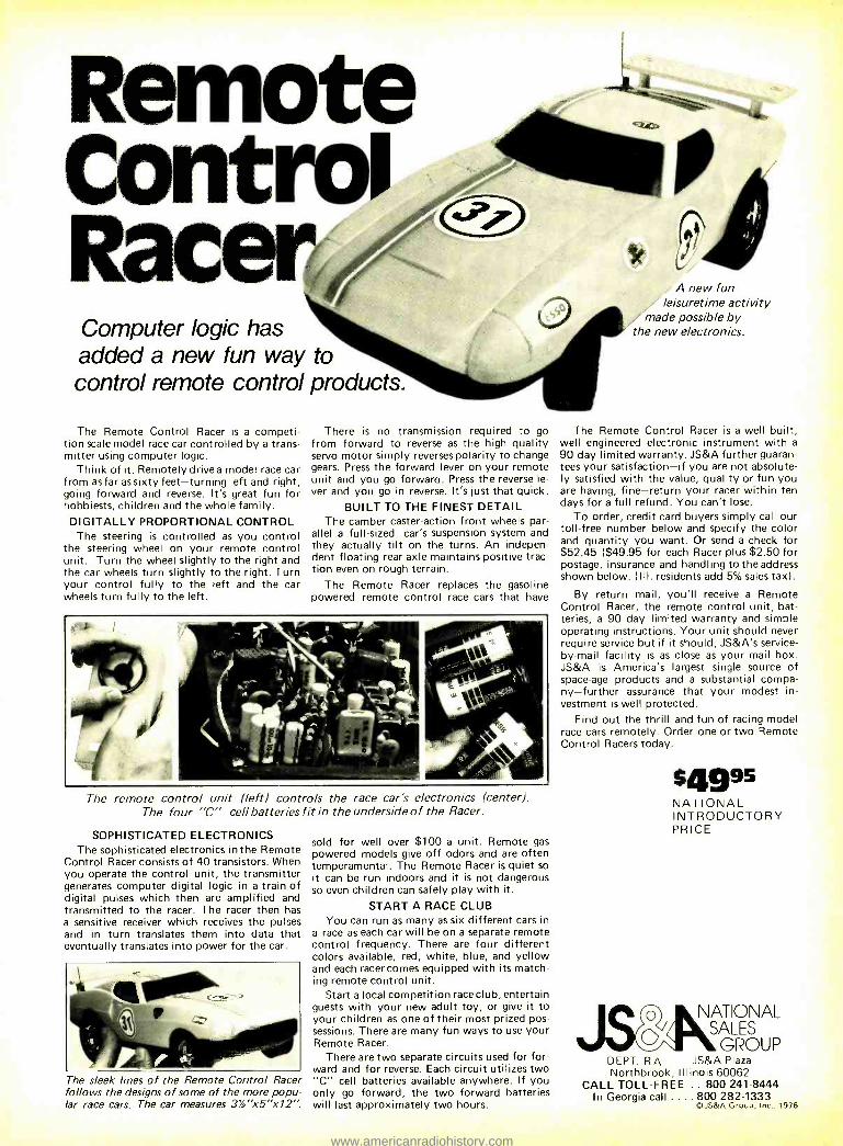
The remote control unit (left) controls the race car's electronics (center). The four "C" cell batteries fit in the underside of the Racer.
SOPHISTICATED ELECTRONICS The sophisticated electronics in the Remote
Control Racer consists of 40 transistors. When you operate the control unit, the transmitter generates computer digital logic in a train of digital pulses which then are amplified and transmitted to the racer. The racer then has a sensitive receiver which receives the pulses and in turn translates them into data that eventually translates into power for the car.
The sleek lines of the Remote Control Racer follows the designs of some of the more popu- lar race cars. The car measures 3% "x5' x 12 ".
sold for well over $100 a unit. Remote gas powered models give off odors and are often temperamental. The Remote Racer is quiet so it can be run indoors and it is not dangerous so even children can safely play with it.
START A RACE CLUB You can run as many as six different cars in
a race as each car will be on a separate remote control frequency. There are four different colors available, red, white, blue, and yellow and each racer comes equipped with its match- ing remote control unit.
Start a local competition race club, entertain guests with your new adult toy, or give it to your children as one of their most prized pos- sessions. There are many fun ways to use your Remote Racer.
There are two separate circuits used for for- ward and for reverse. Each circuit utilizes two "C" cell batteries available anywhere. If you only go forward, the two forward batteries will last approximately two hours.
A new fun leisuretime activity
made possible by the new electronics.
The Remote Control Racer is a well built, well engineered electronic instrument with a
90 day limited warranty. JS &A further guaran- tees your satisfaction -if you are not absolute- ly satisfied with the value, quality or fun you are having, fine -return your racer within ten days for a full refund. You can't lose.
To order, credit card buyers simply call our toll -free number below and specify the color and quantity you want. Or send a check for $52.45 ($49.95 for each Racer plus $2.50 for postage, insurance and handling to the address shown below. (Ill. residents add 5% sales tax).
By return mail, you'll receive a Remote Control Racer, the remote control unit, bat- teries, a 90 day limited warranty and simple operating instructions. Your unit should never require service but if it should, JS &A's service - by -mail facility is as close as your mail box. JS &A is America's largest single source of space -age products and a substantial compa- ny- further assurance that your modest in- vestment is well protected.
Find out the thrill and fun of racing model race cars remotely. Order one or two Remote Control Racers today.
54995 NATIONAL INTRODUCTORY PRICE
o NATIONAL
GROUP DEPT. RA JS &A Plaza Northbrook, Illinois 60062
CALL TOLL -FREE .. 800 241 -8444 In Georgia call .... 800 282 -1333
©JS&A Group, Inc., 1976
www.americanradiohistory.com
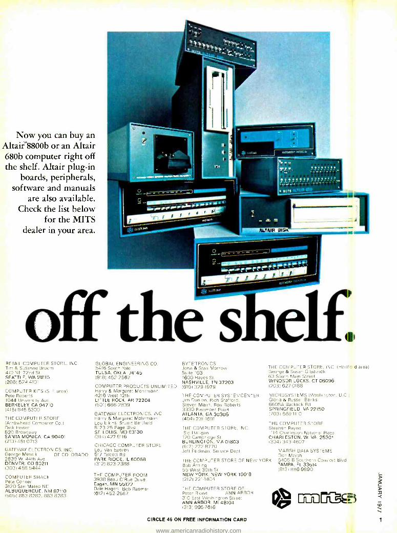
Now you can buy an Altair`M8800b or an Altair 680b computer right off the shelf. Altair plug -in
boards, peripherals, software and manuals
are also available. Check the list below
for the MITS dealer in your area.
off thé shelf1 RETAIL COMPUTER STORE, INC. Tim & Susanne Broom 410 NE 72nd St. SEATTLE, WA 98115 (206) 524 -4101
COMPUTER KITS IS F area) Pete Roberts 1044 University Ave.. BERKELEY, CA 94710 (415) 845 -5300
THE COMPUTER STORE (Arrowhead Compumer Co )
Dick Heiser 820 Broadway SANTA MONICA, CA 90401 (213) 451 -0713
GATEWAY ELECTRONICS, INC. George Mensik OF COLORADO 2839 W. 44th Ave. DENVER, CO 80211 (303) 458 -5444
COMPUTER SHACK Pete Conner 3120 San Mateo NE ALBUQUERQUE, NM 87110 (505) 883 -8282, 863 -8283
GLOBAL ENGINEERING CO. 5416 South Yale TULSA, OKLA. 74145 (918) 452 -2567
COMPUTER PRODUCTS UNLIMITED Harry & Margaret Mohrmann 4216 West 12th LITTLE ROCK, AR 72204 (501) 666 -2839
GATEWAY ELECTRONICS, INC. Harry & Margaret Mohrmann Lou Elkins, Stuart Bartfield 8123 -25 Page Blvd. ST. LOUIS, MO 63130 (314) 427 -6116
CHICAGO COMPUTER STORE Lou Van Eperen 517 Talcott Rd. PARK RIDGE, IL 60068 (312) 823 -2388
THE COMPUTER ROOM 3938 Beau D'Rue Drive Eagan, MN 55122 Dale Hagert, Bob Raemer (612) 452 -2567
BYTE'TRONICS John & Stan Morrow Suite 103 1600 Hayes St. NASHVILLE, TN 37203 (615) 329 -1979
THE COMPUTER SYSTEMCENTER Jim Dumon, Rich Stafford, Steven Mann, Ron Roberts 3330 Piedmont Road ATLANTA, GA 30305 (404) 231-1691
THE COMPUTER STORE, INC. Sid Halligan
120 Cambridge St. BURLINGTON, MA 01803 (617) 272-8770 Jeff Feldman, Service Dept.
THE COMPUTER STORE, INC. (Hartfo d areal George & Susan Gilpatock 63 South Main Street WINDSOR LOCKS. CT 06096 (203) 627 -0188
MICROSYSTEMS (Washington. D.0 Gloria & Russell Banks 6605A Backlick Rd. SPRINGFIELD, VA 22150 (703) 569 -1110
THE COMPUTER STORE Stephen Payne 1114 Charleston National Plaza CHARLESTON, W. VA. 25301 (304) 3434607
THE COMPUTER STORE OF NEW YORK Bob Arning 55 West 39th St. NEW YORK. NEW YORK 10018 (212) 221 -1404
THE COMPUTER STORE OF Peter Blond ANN ARBOR 310 East Washington Street ANN ARBOR, MI 48104 (313) 995 -7616
MARSH DATA SYSTEMS Don Marsh 5405 B Southern Comfort Blvd TAMPA, FL 33614 18131 886 -9890
p IMDM0.s CIRCLE 46 ON FREE INFORMATION CARD i
www.americanradiohistory.com
Sylvania introduces the first 5 -year warranty' on picture tubes.
How can we give you a limited warranty this good?
Because we have complete con- fidence that our Color Bright 85` picture tubes will outlast this 5 -year warranty and keep on giving your customers beautiful pictures.
We produce these tubes on the same equipment as our All -New line which is sold as original equipment to TV set manufacturers.
It's terrific to be able to offer your customers a high -quality tube with a
warranty like this at no risk to you. There's good profit in it, too. So get in touch with your local distributor today, and get cracking on your first five years. *Limited Warranty, naturally. It doesn't cover labor for replacing a tube.
CD3 SYLVANIA GTE Sylvania, Electronic Components Group. 100 First Ave., Waltham. MA. 02154
www.americanradiohistory.com
Radio-Electronics. THE MAGAZINE FOR NEW IDEAS IN ELECTRONICS
Electronics publishers since 1908 JANUARY 1977 Vol. 48 No. 1
SPECIAL FEATURES
39 TV Games Part II -Final section in this comprehensive look at what you can buy. by Fred Blechman
61 IC Application Of The Month Complete information on how to use General Instrument's Video Game IC.
CB RADIO 43 23 Or 40 -When Should You Buy? How to get the most for your money. by Fred Petras
BUILD ONE OF THESE
31 Portable Mini Organ Part I: Play music anywhere with this self- contained five - octave organ. by John S. Simonton
35 Digital LED Clock For Your Car Accurate four -digit LED clock in a compact size for your dashboard. by Robert C. Arp
COMPUTERS 22 Komputer Korner Generating a UART function using software. by Paul Field, David Larsen, Peter Rony and John Titus
66 Timeshare -Turn Your Minicomputer Into A Maxi Your minicomputer can be used to access a full -scale computer system. by Patrick Godding
GENERAL ELECTRONICS
4 Looking Ahead Tomorrow's news today. by David Lachenbruch
29 Equipment Report Sencore DVM35 digital voltmeter
46 Analog Voltmeters An in -depth look at how they work and how to use them. by Charles Gilmore
HI -FI AUDIO
STEREO
26 Equipment Report Heath AS -1344 Speakers
49 How Noise Is Measured Know what the noise specs mean before you compare. by Len Feldman
56 R -E Lab Test Report Sony STR- 6800SD Receiver.
59 R -E Lab Test Report Yamaha B -2 Amplifier.
TELEVISION 68 Step -By -Step Troubleshooting Color bandpass amplifiers. by Jack Darr
75 Service Clinic Fast recovery diodes by Jack Darr
77 Reader Questions R -E's Service Editor solves reader problems
DEPARTMENTS 88 Advertising Index 12 Advertising Sales Offices 14 Letters 6 New & Timely
80 New Products 85 Next Month 89 Reader Service Card
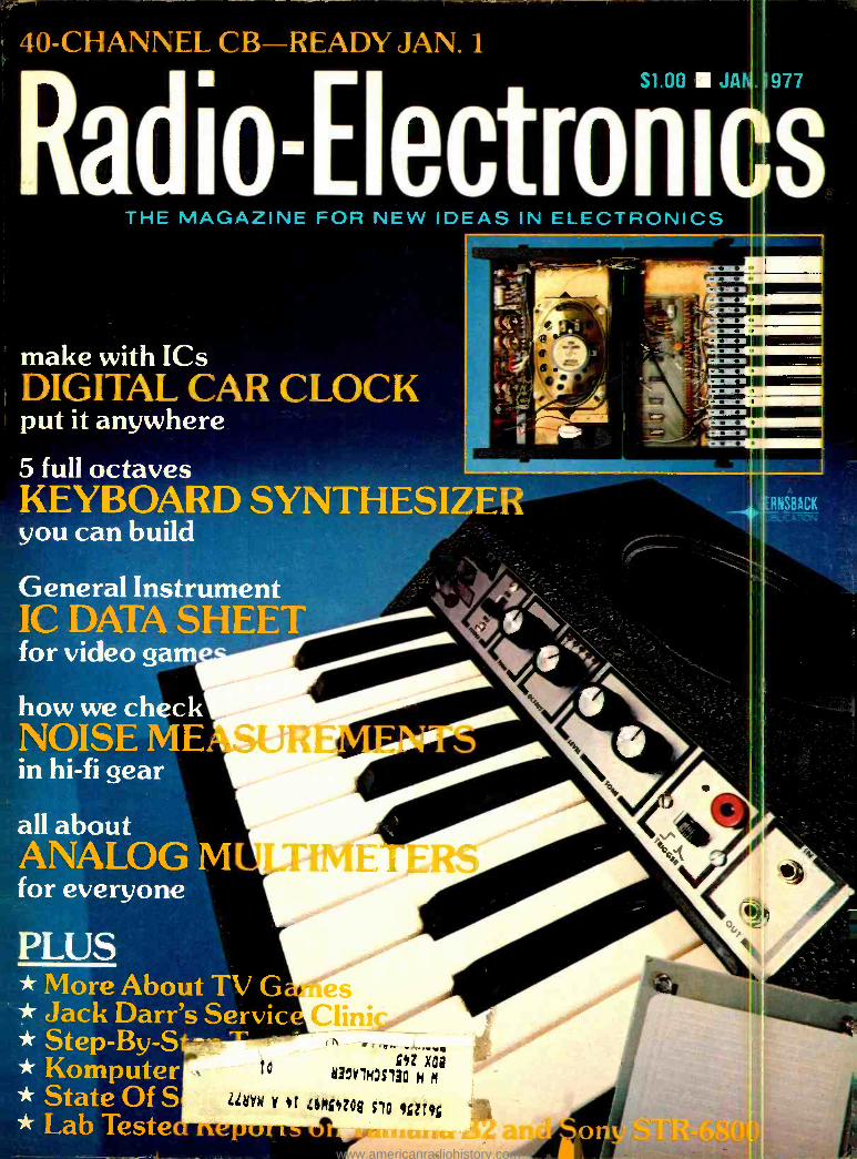
ON THE COVER Electronic music o -c ans have been around for c uite awhile, but portable organs are really unique. This one is completely self -conta ned with speaker, battery and keyboard, and it cove .s a
five -octave range. The on- struction details star of page 31.
Spice up your car with this Digital L E ) Clock. The construction details start on pate 35.
o
10
20
-30
pllll 5IIIINi1I 011111111111111
,II,.A,
111111i
IIIIIII
II II I I
11, 11111111 1 20Hz 100 1kHz
FREQUENCY
20kHz
You can't compare noise specs to) h i -fi gear unless you know how they are meast rei. An in- depth look at how noise measurem nts are made starts on page 49.
Radio- Electronics, Published monthly by C ernsback Publications, Inc., 200 Park Avenue South, r ew York, NY 10003. Phone: 212 -777 -6400. Second -c as postage paid at New York, NY and additional ma fir: offices. One -year subscription rate: U.S.A.. U.S. pc .sessions and Canada, $8.75. Pan -American count iev $10.25. Other countries, $10.75. Single copies $1.0) 1976 by Gernsback Publications, Inc. All rights rese ve: Printed in U.S.A.
Subscription Service: Mail all subscrip ion. orders, changes, correspondence and Postmaste h tices of undelivered copies (Form 3579) to Radic -E actronics Subscription Service, Box 2520, Boulder, C O 30302.
A stamped self- addressed envelope must ac cc npany all submitted manuscripts and /or artwork or ph ct graphs if their return is desired should they be r3le:ted. We disclaim any responsibility for the loss or : mage of manuscripts and /or artwork or photograph= le in our possession or otherwise.
As a service to readers, Radio- Electronics publishes available plans or information relating to newsworthy products, techniques and scientific and technological diva opments. Because of possible variances in the quality and condition of materials and workmanship used by readers, Radio- Electronics disclaims any responsibility for the sat r a rd proper functioning of reader -built projects based upon or from plans or information published in this magazine.
www.americanradiohistory.com
looking ahead
Projection report
Advent says it produced about 6,000 projection televi- sion systems in 1976, and its doubtful whether the rest of the projection -TV industry - consisting of up to 30 or 40 companies, mostly small - made much more than that all together despite their opti- mistic forecasts early in the year. Most of the other "home" projection TV manu- facturers actually assemble their systems from modified, small- screen color sets, lenses, screens and cabinets. Sony was probably the inspira- tion for this type of set, having had one on the market for two years (but using a special trini- tron tube for high brightness). Some of the larger corpora- tions are beginning to take an interest in projection. Admiral, a subsidiary of Rockwell Inter- national, has been experiment- ing with giant- screen TV, and several months ago Sega En- terprises, a subsidiary of Gulf & Western, purchased a pro- jection television company.
The company it purchased was Muntz Home Theatre, founded by the same "Madman" Muntz who starred in TV's early days with the first low- priced mass -marketed television sets and later intro- duced car stereo. Now Sega has started to distribute its "Segavision" line of projection TV at $995 to $2,395. Mean- while, Muntz has started up a new company and is back in the projection -TV business. Al- though his firm's name is
Muntz Electronics, he can't advertise it because Sega ob- tained an injunction, claiming it bought the Muntz name as well as the business. So, with his usual flair for turning a liability into an asset, Muntz is now advertising his company as "Madman Electronics," with sets priced from $795 to $1,595.
7 -hour VTR?
While the debate continues over the optimum playing/
recording time for home video- cassette recorders, Sony is
expected to introduce soon an accessory for its enormously successful Betamax that ex- tends unattended recording time to as much as seven hours. The accessory is a changer. In at least one pre- production version seen in To- kyo, the changer's bin permit- ted the stacking of up to seven one -hour cassettes. The cas- settes are changed automati- cally-a new one drops into place as the previous one is rejected.
The changer, as viewed in prototype, incorporates a digi- tal timer with LED readout, permitting either uninterrupted or on- off -on -off recording while unattended. Thus a night -shift worker could tape all evening programs on one channel from 6 PM to 1 AM for viewing after he came home from work.
Magnetic disc recorder
For the last three years, this column has reported occa- sionally on the magnetic disc recorder (MDR) being devel- oped by Erich Rabe as a TV attachment to both record and play back in color. With each demonstration, picture quality has improved (although it has never seemed quite good enough for commercializa- tion), and the major drawback has been its extremely short recording time. Now, even be- fore the short- playing version has been introduced, Rabe has developed an LP version designed to have a playing time of two hours per disc.
The LP disc is understood to be about' /4 -inch thick, looking something like an old Edison record. The outside three inches are composed of mag- netic material with deeply -cut grooves. Each groove is de- signed to accommodate 24 spiral magnetic tracks, which are deposited into the groove wall by the magnetic recording head. The head presumably travels the spiral groove from start to center of the disc, then changes to track two and
repeats the process, and so on, until all 24 tracks have been recorded. The system's promoters say some versions of MDR should be on the market in Europe and the U.S. during 1977. But, as this column has so often warned, don't ever hold your breath waiting for a videodisc.
Kloss leaves Advent
Henry Kloss, founder of Ad- vent Corporation and one of the leading innovators in American consumer electron- ics, has left the company of which he was once president and more recently technical director. His main work, he said, was finished with the successful launching of two models of the VideoBeam pro- jection television system. Un- der Kloss's supervision, Ad- vent also introduced the first consumer Dolby adaptor and the first Dolbyized cassette recorder. Before founding Ad- vent, Kloss was a co- founder of Acoustic Research and KLH, which pioneered air - suspension speakers and compact stereo, respectively. Wherever he shows up next, you can be sure there'll be more innovation.
TVI crackdown?
Some hints that the FCC may push to force television receiver manufacturers to in- clude interference filtering in all sets were contained in a
recent FCC order reiterating its expansion of CB to 40 channels and temporarily re- jecting proposals to increase 60-dB harmonic suppression requirement for Class -D CB transmitters. The Commission took a stronger stand than ever before that most of the fault for TVI lies in the TV rather than the transmitter. Said the FCC's decision: "Although it is quite true that harmonic radiation from some Class -D transmitters causes TVI some of the time to some television receivers, it is equal-
ly true that the majority of the TVI complaints received by the Commission result directly from poor TV receiver design, lack of adequate filtering in TV receivers presently on the market, and inability of TV receivers adequately to reject unwanted or adjacent -channel signals. Indeed, in fiscal 1975, 82% of all RF interference complaints were traced to home entertainment equip- ment design deficiencies."
In the last Congress, three bills aimed at putting the onus of TVI on the TV receiver manufacturers' backs failed to reach a hearing or a vote - possibly because the FCC de- clined to take a stand on them. The Commission currently has no power to require receiver manufacturers to include inter- ference- protection in their sets. Set makers generally pro- vide filters on request, usually without charge.
With the rapid growth of CB, the FCC's recent statements may indicate it plans to take a
stronger stand and possibly request authority to regulate receivers. At the same time, the Commission proposes to tighten up harmonic suppres- sion standards in CB transmit- ters, perhaps to 100 dB -but probably not this year.
Antenna warning
Be careful -your CB anten- na could be lethal. The Con- sumer Product Safety Com- mission says it's studying the problem of what to do about the hazard of electrocutions from base -station antennas as result of their coming into contact with high -voltage lines. The Commission says about 30 people were killed in the first four months of 1976 as the result of such mishaps. The most likely outcome will be a requirement that a strong warning label be printed on packages containing commu- nications antennas, or at- tached directly to the anten- nas.
DAVID LACHENBRUCH CONTRIBUTING EDITOR
www.americanradiohistory.com
Now...pushbutton remote TV control...
for all channels... for all TV sets.
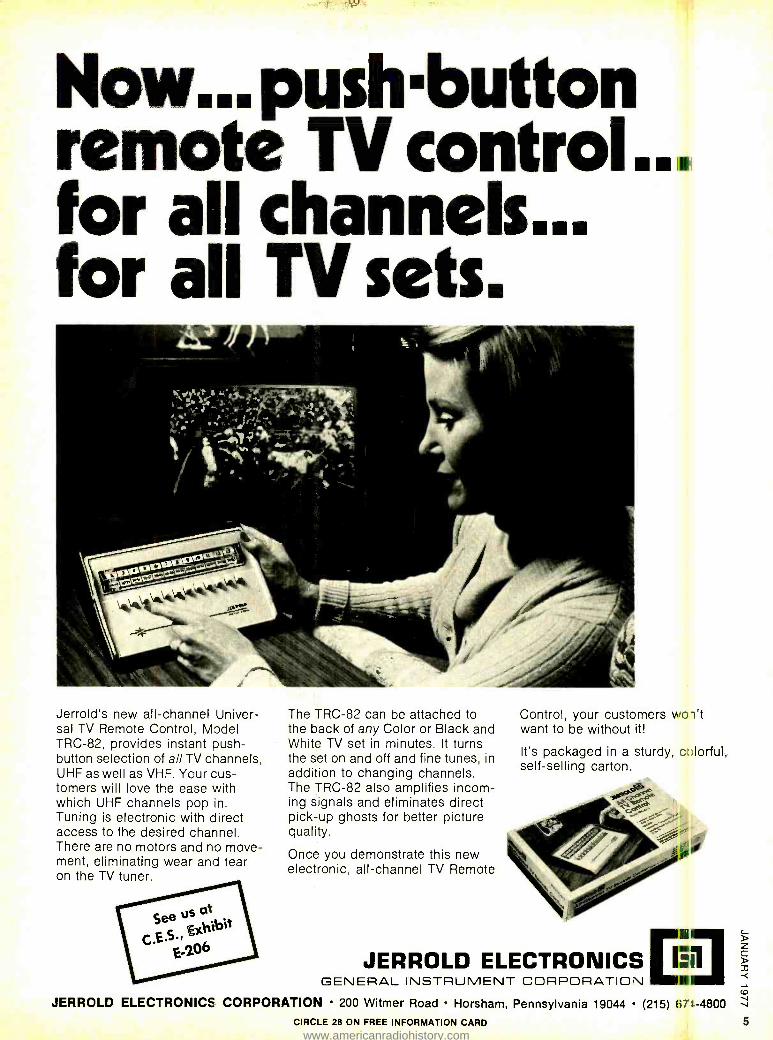
Jerrold's new all- channel Univer- sal TV Remote Control, Model TRC -82, provides instant push- button selection of all TV channels, UHF as well as VHF. Ycur cus- tomers will love the ease with which UHF channels pop in. Tuning is electronic with direct access to the desired channel. There are no motors and no move- ment, eliminating wear and tear on the TV tuner.
The TRC -82 can be attached to the back of any Color or Black and White TV set in minutes. It turns the set on and off and fine tunes, in addition to changing channels. The TRC -82 also amplifies incom- ing signals and eliminates direct pick -up ghosts for better picture quality.
Once you demonstrate this new electronic, all- channel TV Remote
Control, your customers wc-i't want to be without it!
It's packaged in a sturdy, c Horful, self -selling carton.
u
JERROLD ELECTRONICS GENERAL INSTRUMENT CORPORATION I
JERROLD ELECTRONICS CORPORATION 200 Witmer Road Horsham, Pennsylvania 19044 (215) 1i71.-4800
CIRCLE 28 ON FREE INFORMATION CARD 5
www.americanradiohistory.com
new e timely
Third Marisat now in orbit; will aid Navy, act as standby
An addition to the two Marisat satellites now in use was launched by NASA last October into an orbit over the Indian Ocean. It will be used by the Navy. Its position is 73 degrees east longitude, near the Maldive Islands, south of India. The present Atlantic Marisat is at 15 degrees West and the Pacific satellite at 176 degrees East. They are relaying high - quality voice, Telex, facsimile and data over both oceans for ships and off -shore oil drilling crews. They also serve the Navy's fleet communications require- ments.
improvement in speed and reliability over surface radio. Exxon, testing the system on five of its tankers, reports that Telex messages by satellite were being received immediately, while messages by the older marine radiotelegraph took over five hours to get through in some cases.
One thousand CB clinics to study 40- channel band
Sencore, manufacturer of electronic testing and manufacturing equipment, will hold more than 1000 CB service clinics throughout the country, beginning late 1976 and continuing through this Spring. The clinics will be directed at the new 40- channel Class -D CB spectrum and will be carried on with the help of Sencore's two new pieces of equipment, the CB41 Auto- matic Performance Tester and the CB42 CB Analyzer.
The clinics will cover the technical needs of both field service and bench technicians, the CB41 being adapted to field work, including installations, and the CB42 totally equipping a bench for CB servicing. Both are designed to save the technician's time, making measurements by pushbutton that formerly required adjusting several controls.
Information as to dates and locations of the clinics may be obtained from any of Sencore's Full Line Promotional Distribu- tors.
ISCET names Technician of the Year
James E. Harris, CET, service manager of Tarpley's TV, Temple, TX, was named "Technician of the Year" by the Interna- tional Society of Certified Technicians (ISCET) at their convention in San Anto- nio, TX, last August 15.
The award winner is determined on the basis of scores received in professional proficiency, efficiency, product produc- tivity and customer relations, and in industry and community involvement.
Mr. Harris was nominated by the Twin Lakes chapter of the Texas Electronics Association (TEA) which he serves as secretary- treasurer and ISCET certifica- tion administrator, and was selected in
balloting conducted by Service Shop magazine and ISCET.
The new Technician of the Year, besides his professional and association work, serves on the technical education advisory board of Central Texas College, teaches night classes at Temple Junior College and conducts numerous training sessions for area technicians.
Both the Technician of the Year and the runnerup received watches incorporating the ISCET logo and the statement "Technician of the Year 1976." Both awards are provided by Radio -Electronics magazine.
continued on page 12
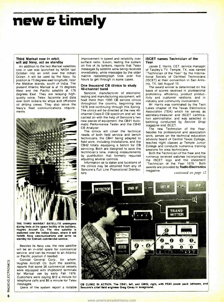
THE THIRD MARISAT SATELLITE undergoes during tests at the space facility of Its builders, Hughes Aircraft Co. The new satellite is stationed over the Indian Ocean, where it will handle Navy communications and serve as standby for Comsat commercial service.
Besides its Navy use, the new satellite will be an in -orbit spare for commercial service, and can be moved to an Atlantic or Pacific position if needed.
Comsat General Corp., for whom Hughes Aircraft Co. built the satellite, reports that some 26 commercial vessels were equipped with shipboard terminals for Marisat use by early Fall 1976. Customers were paying $10 a minute for telephone calls and $6 a minute for Telex messages.
Users of the system report a notable CB CLINIC IN ACTION. The CB41, left, and CB42, right, with PS43 power pack between, and Sencore's chief field engineer Greg Carey In foreground.
www.americanradiohistory.com
All SB 23-channel
CB units
E
have a 40-channel
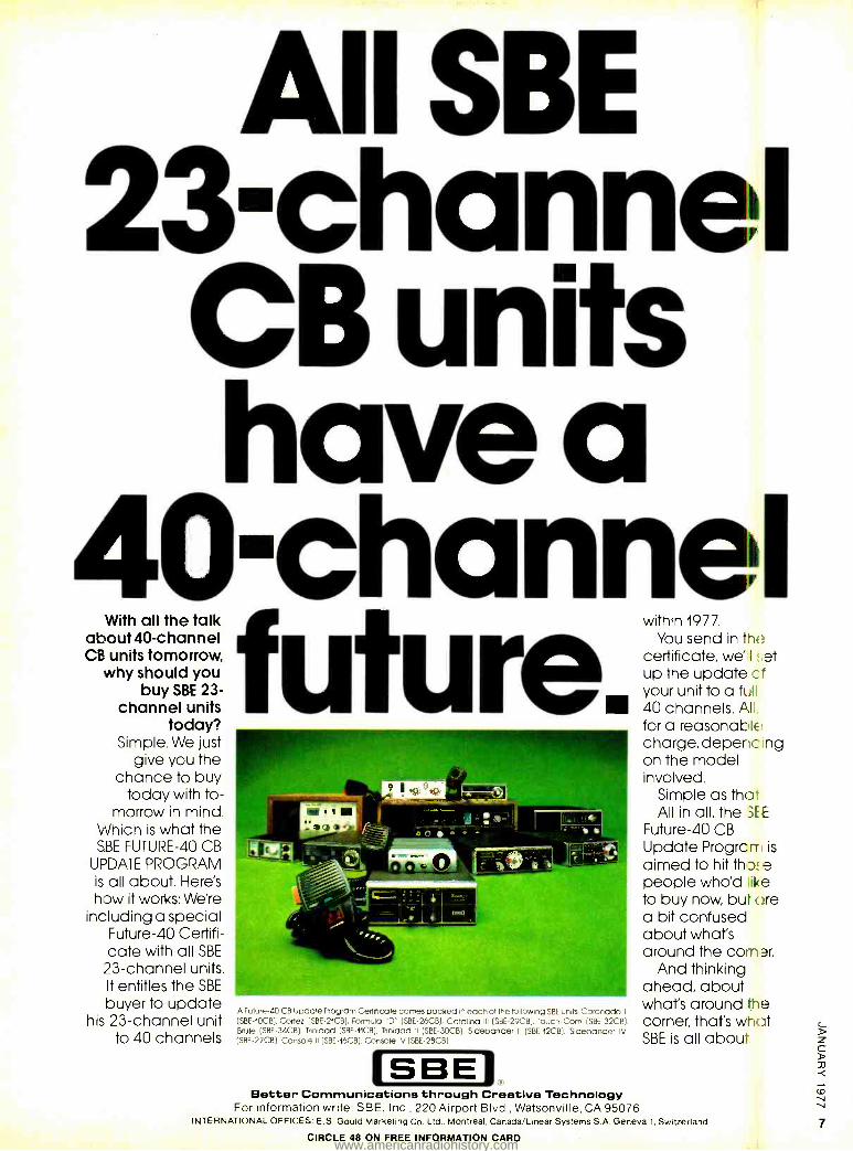
With all the talk within 1977. about40- channel You send in the CB units tomorrow, certificate, wé I r,et
why should you up the update cf buy SBE 23- your unit to a full
channel units 40 channels. All, today? for a reasonable
Simple. We just charge, depencing give you the on the model
chance to buy involved. today with to 7 :' : Simple as that
morrow in mind. All in all, the SEE
Which is what the ='` _ =.. Future -40 CB SBE FUTURE -40 CB --- Update Progrcr is
_ 1= - -.,.. - UPDATE PROGRAM .. 9 O' - ç aimed to hit th _I! e is all about. Here's people who'd e how it works: Were c = j to buy now bu :re
including a special 'f _ a bit confused Future -40 Certifi- about what's cate with all SBE around the car ?,r.
23- channel units. And thinking It entitles the SBE ahead, about buyer to update what's around the A Future -40 CB Update Program Certificate comes packed in each of the following SBE units. Coronado II
his 23- channel unit (SBE- 10CB).Cortez (SBE- 21CB), Formula "D" (SBE- 26CB), Catalina III (SBE- 29CB), Touch Com (SBE- 32CB), corner, that's what Brute (SBE- 34CB). Trinidad (SBE- 11CB), Trinidad II (SBE-30CB), Sidebander II (SBE- 12CB). Sidebander IV
to 40 channels (SBE- 27CB). Console II (SBE- 16CB), Console IV (SRI ?KB? SBE is all about.
ISBEI Better Communications through Creative Technology
For information write: SBE, Inc., 220 Airport Blvd., Watsonville. CA 95076 INTERNATIONAL OFFICES: E. S. Gould Marketing Co. Ltd.. Montreal. Canada /Linear Systems S A. Geneva 1, Switzerland
CIRCLE 48 ON FREE INFORMATION CARD 7
www.americanradiohistory.com
Learn to service Communications/CB equipment at home...with
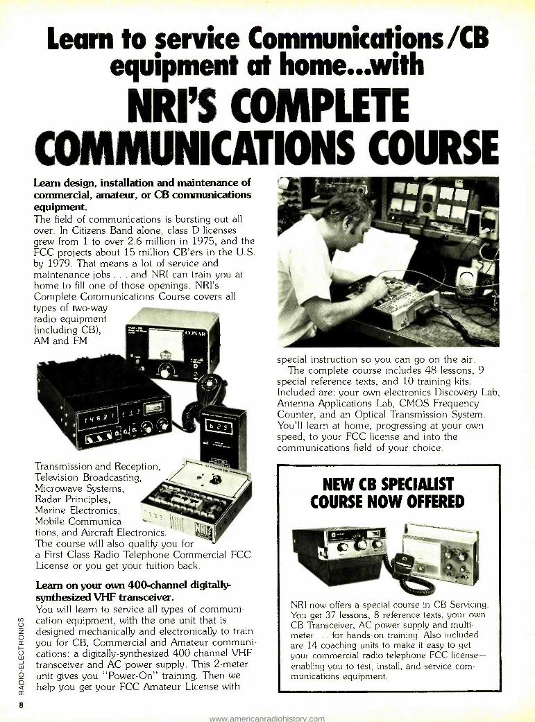
NRI'S COMPLETE COMMUNICATIONS COURSE Learn design, installation and maintenance of commercial, amateur, or CB communications equipment. The field of communications is bursting out all over. In Citizens Band alone, class D licenses grew from 1 to over 2.6 million in 1975, and the FCC projects about 15 million CB'ers in the U.S. by 1979. That means a lot of service and maintenance jobs ... and NRI can train you at home to fill one of those openings. NRI's Complete Communications Course covers all types of two -way radio equipment (including CB), AM and FM
Transmission and Reception, Television Broadcasting, Microwave Systems, Radar Principles, Marine Electronics, Mobile Communica- tions, and Aircraft Electronics. The course will also qualify you for a First Class Radio Telephone Commercial FCC License or you get your tuition back.
Learn on your own 400 -channel digitally - synthesized VHF transceiver. You will learn to service all types of communi- cation equipment, with the one unit that is
designed mechanically and electronically to train you for CB, Commercial and Amateur communi- cations: a digitally- synthesized 400 - channel VHF transceiver and AC power supply. This 2 -meter unit gives you "Power -On" training. Then we help you get your FCC Amateur License with
special instruction so you can go on the air. The complete course includes 48 lessons, 9
special reference texts, and 10 training kits. Included are: your own electronics Discovery Lab, Antenna Applications Lab, CMOS Frequency Counter, and an Optical Transmission System. You'll learn at home, progressing at your own speed, to your FCC license and into the communications field of your choice.
NEW CB SPECIALIST
COURSE NOW OFFERED
NRI now offers a special course in CB Servicing. You get 37 lessons, 8 reference texts, your own CB Transceiver, AC power supply and multi - meter ... for hands -on training. Also included are 14 coaching units to make it easy to get your commercial radio telephone FCC license - enabling you to test, install, and service com- munications equipment.
www.americanradiohistory.com
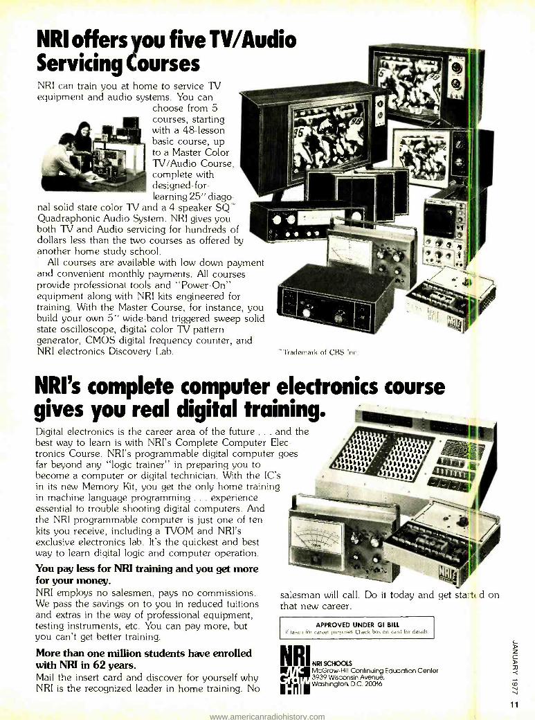
NRI offers you five TV /Audio Servicing Courses NRI can train you at home to service TV equipment and audio systems. You can
choose from 5 courses, starting with a 48- lesson basic course, up to a Master Color TV /Audio Course, complete with designed -for- learning 25" diago-
nal solid state color TV and a 4- speaker SQ'' Quadraphonic Audio System. NRI gives you both TV and Audio servicing for hundreds of dollars less than the two courses as offered by another home study school.
All courses are available with low down payment and convenient monthly payments. All courses provide professional tools and "Power -On" equipment along with NRI kits engineered for training. With the Master Course, for instance, you build your own 5" wide -band triggered sweep solid state oscilloscope, digital color TV pattern generator, CMOS digital frequency counter, and NRI electronics Discovery Lab. 'Trademark of CBS Inc.
NRI's complete computer electronics course gives you real digital training. Digital electronics is the career area of the future ... and the best way to learn is with NRI's Complete Computer Elec- tronics Course. NRI's programmable digital computer goes far beyond any "logic trainer" in preparing you to become a computer or digital technician. With the IC's in its new Memory Kit, you get the only home training in machine language programming ... experience essential to trouble shooting digital computers. And the NRI programmable computer is just one of ten kits you receive, including a TVOM and NRI's exclusive electronics lab. It's the quickest and best way to learn digital logic and computer operation.
You pay less for NRI training and you get more for your money. NRI employs no salesmen, pays no commissions. We pass the savings on to you in reduced tuitions and extras in the way of professional equipment, testing instruments, etc. You can pay more, but you can't get better training.
More than one million students have enrolled with NRI in 62 years. Mail the insert card and discover for yourself why NRI is the recognized leader in home training. No
salesman will call. Do ii today and get sta:1 d on that new career.
APPROVED UNDER GI BILL if taken for career purposes Check box an card for details.
NRIN. ( ' McGraw -Hill Continuing Education Center
3939 Wisconsin Avenue,
I. ri Washington, D.C. 20016
11
www.americanradiohistory.com
new t I e' continued from page 6
Bartlett, Kelley and Porter get Gernsback awards
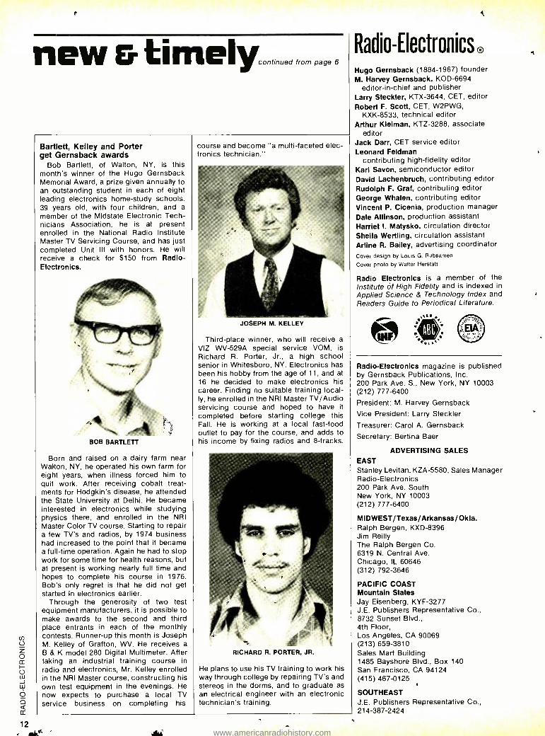
Bob Bartlett, of Walton, NY, is this month's winner of the Hugo Gernsback Memorial Award, a prize given annually to an outstanding student in each of eight leading electronics home -study schools. 39 years old, with four children, and a
member of the Midstate Electronic Tech- nicians Association, he is at present enrolled in the National Radio Institute Master TV Servicing Course, and has just completed Unit Ill with honors. He will receive a check for $150 from Radio - Electronics.
BOB BARTLETT
Born and raised on a dairy farm near Walton, NY, he operated his own farm for eight years, when illness forced him to quit work. After receiving cobalt treat- ments for Hodgkin's disease, he attended the State University at Delhi. He became interested in electronics while studying physics there, and enrolled in the NRI Master Color TV course. Starting to repair a few TV's and radios, by 1974 business had increased to the point that it became a full -time operation. Again he had to stop work for some time for health reasons, but at present is working nearly full time and hopes to complete his course in 1976. Bob's only regret is that he did not get started in electronics earlier.
Through the generosity of two test equipment manufacturers, it is possible to make awards to the second and third place entrants in each of the monthly contests. Runner -up this month is Joseph M. Kelley of Grafton, WV. He receives a
B & K model 280 Digital Multimeter. After taking an industrial training course in radio and electronics, Mr. Kelley enrolled in the NRI Master course, constructing his own test equipment in the evenings. He now expects to purchase a local TV service business on completing his
course and become "a multi- faceted elec- tronics technician."
JOSEPH M. KELLEY
Third -place winner, who will receive a
VIZ WV -529A special service VOM, is Richard R. Porter, Jr., a high school senior in Whitesboro, NY. Electronics has been his hobby from the age of 11, and at 16 he decided to make electronics his career. Finding no suitable training local- ly, he enrolled in the NRI Master TV /Audio servicing course and hoped to have it completed before starting college this Fall. He is working at a local fast -food outlet to pay for the course, and adds to his income by fixing radios and 8- tracks.
RICHARD R. PORTER, JR.
He plans to use his TV training to work his way through college by repairing TV's and stereos in the dorms, and to graduate as an electrical engineer with an electronic technician's training.
Radio-Electronics® Hugo Gernsback (1884 -1967) founder M. Harvey Gernsback, KOD -6694
editor -in -chief and publisher Larry Steckler, KTX -3644, CET, editor Robert F. Scott, CET, W2PWG,
KXK -8533, technical editor Arthur Kleiman, KTZ -3288, associate
editor Jack Darr, CET service editor Leonard Feldman
contributing high -fidelity editor Karl Savon, semiconductor editor David Lachenbruch, contributing editor Rudolph F. Graf, contributing editor George Whalen, contributing editor Vincent P. Cicenia, production manager Dale Allinson, production assistant Harriet I. Matysko, circulation director Sheila Wertling, circulation assistant Arline R. Bailey, advertising coordinator Cover design by Louis G. Rubsamen
Cover photo by Walter Herstatt
Radio Electronics is a member of the Institute of High Fidelity and is indexed in
Applied Science & Technology Index and Readers Guide to Periodical Literature.
k +- Radio -Electronics magazine is published by Gernsback Publications, Inc. 200 Park Ave. S., New York, NY 10003 (212) 777 -6400
President: M. Harvey Gernsback
Vice President: Larry Steckler
Treasurer: Carol A. Gernsback
Secretary: Bertina Baer
ADVERTISING SALES EAST Stanley Levitan, KZA -5580, Sales Manager Radio -Electronics 200 Park Ave. South New York, NY 10003 (212) 777 -6400
MIDWEST /Texas /Arkansas /Okla. Ralph Bergen, KXD -8396 Jim Reilly The Ralph Bergen Co. 6319 N. Central Ave. Chicago, IL 60646 (312) 792 -3646
PACIFIC COAST Mountain States Jay Eisenberg, KYF -3277 J.E. Publishers Representative Co., 8732 Sunset Blvd., 4th Floor, Los Angeles, CA 90069 (213) 659 -3810 Sales Mart Building 1485 Bayshore Blvd., Box 140 San Francisco, CA 94124 (415) 467 -0125
SOUTHEAST J.E. Publishers Representative Co., 214- 387 -2424
www.americanradiohistory.com
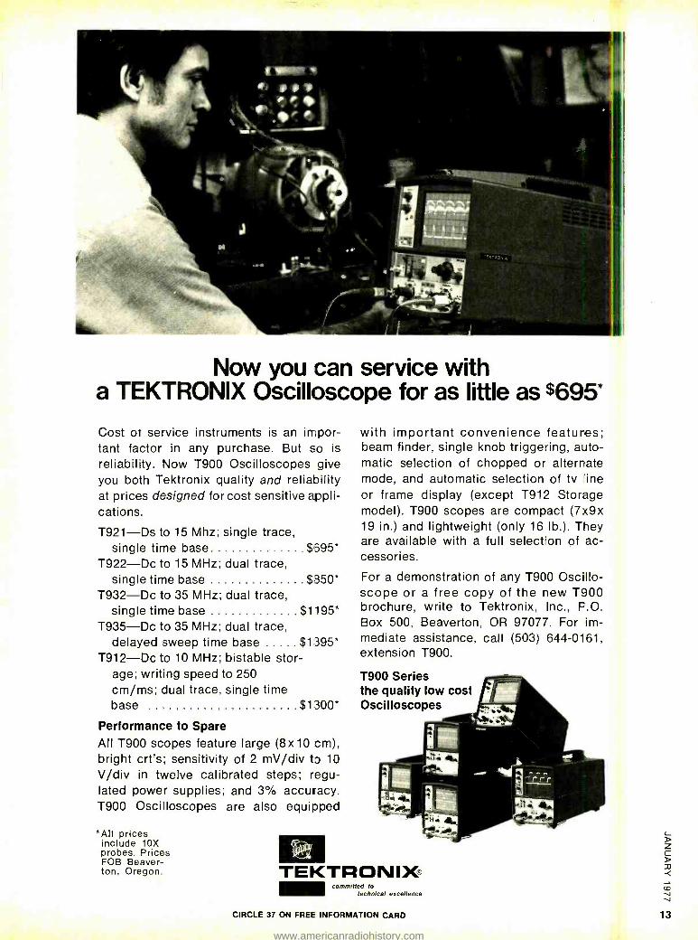
Now you can service with a TEKTRONIX Oscilloscope for as little as $695*
Cost of service instruments is an impor- tant factor in any purchase. But so is
reliability. Now T900 Oscilloscopes give you both Tektronix quality and reliability at prices designed for cost sensitive appli- cations.
T921 -Ds to 15 Mhz; single trace, single time base $595*
T922 -Dc to 15 MHz; dual trace, single time base $850*
T932 -Dc to 35 MHz; dual trace, single time base $1195*
T935 -Dc to 35 MHz; dual trace, delayed sweep time base $1,395*
T912 -Dc to 10 MHz; bistable stor- age; writing speed to 250 cm /ms; dual trace, single time base $1300*
Performance to Spare All T900 scopes feature large (8x10 cm), bright crt's; sensitivity of 2 mV /div to 10
V /div in twelve calibrated steps; regu- lated power supplies; and 3% accuracy. T900 Oscilloscopes are also equipped
*All prices include 10X probes. Prices FOB Beaver- ton, Oregon.
with important convenience features; beam finder, single knob triggering, auto- matic selection of chopped or alternate mode, and automatic selection of tv dine
or frame display (except T912 Storage model). T900 scopes are compact (7x9x 19 in.) and lightweight (only 16 lb.). They are available with a full selection of ac- cessories.
For a demonstration of any T900 Oscillo- scope or a free copy of the new T900 brochure, write to Tektronix, Inc., F.O. Box 500, Beaverton, OR 97077. For im- mediate assistance, call (503) 644 -0161, extension T900.
T900 Series the quality low cost Oscilloscopes
TEKTRONIX® committed to
technical excellence
CIRCLE 37 ON FREE INFORMATION CARD
www.americanradiohistory.com
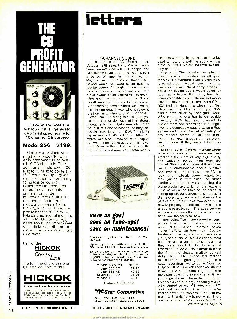
THE
CB
PROFIT
GENERATOR
Hickok introduces the first low -cost RF generator designed specifically for 40 channel CB service.
Model 256 S199. Here's every signal you
need to service CBs with easy precision tuning over all 40 CB channels. Four additional bands cover 100 kHz to 16 MHz to cover any IF. A counter output gives exact frequency monitoring for precision control. Calibrated RF attenuator output provides stable signals from under 1
microvolt to over 100,000 microvolts. An internal modulator gives a 1 kHz, 0 -100% tone, and there are provisions for 20 Hz to 10 kHz external modulation. Its all the RF Generator you need, so why pay more? See your Hickok distributor for more information or contact us directly.
Part of the HICKOK Comm L
ine the full line of professional CB service instruments.
HICKOK the value innovator INSTRUMENTATION E. CONTROLS DIVISION THE HICKOK ELECTRICAL INSTRUMENT CO. 10514 Dupont Avenue Cleveland, Ohio 44108 1216) 541 -3060 TWE 810- 421 -8286
letters
4- CHANNEL SOUND In his article on AM Stereo in the
October 1976 issue, Harry Maynard men- tioned an interview with 500 people who have lived with quadriphonic systems over a period of time. In this article, Mr. Maynard said that 95% of those inter- viewed would not want to go back to regular stereo. Although I wasn't one of those interviewed, I agree entirely. I'm a
proud owner of an expensive, do- every- thing quad system, and I couldn't see myself reverting to two -channel sound. But something seems wrong somewhere, and I'm one quadri -freak who isn't going to sit on his woofers and let it happen!
What am I referring to? I'm glad you asked. It's all to obvious that the interest in quad is declining, but it seems to me it's the fault of a closed- minded industry that couldn't care less. No, I DON'T think it's the economy that's killing it. After all, stereo was also somewhat more expen- sive when it first came out than it is now. I
think it's more likely that the bulk of the hardware and software manufacturers are
save on gas! save on tune -ups! save on maintenance! Electronic ignition is "IN "I So says Detroit. Update your car with either a TIGER CD or a TIGER I breakerless system.
Enjoy the benefits of better gas mileage, quicker starting, elimination of tune -ups, 50,000 miles on points and plugs, and reduced maintenance expenses.
TIGER MAX CD $69.95 TIGER 500 CD 59.95 TIGER SST CD 42.95 SIMPLIKIT CD 31.95 TIGER I 45.95
Postpaid U.S.A. only.
1Star Corporation Dept. WW, P.O. Box 1727 Grand Junction, Colorado 81501
CIRCLE 53 ON FREE INFORMATION CARD CIRCLE 7 ON FREE INFORMATION CARD
the ones who are trying their best to lay quad to rest and pull the sod over the grave, but it's a mistake for them to think they can do it.
First point: The industry has failed to come up with a standard for all quad records. If a standard quad system were to be adopted, it would have to offer as much as it can without compromises. I
doubt the buying public would settle for less that a totally discrete system that offers compatibility with stereo and mono players. Only one does, and that's CD -4. RCA had the right idea when they first introduced the Quadradisc, and they should have stuck by their guns when WEA made the decision to go double inventory. RCA had also planned to release most new recordings in a single - inventory compatible quad -disc form that, as they said, could take full advantage of any modern stereo or discrete quad system. But RCA reneged on their prom- ise. I wonder if they know it isn't too late?
Second point: Several manufacturers have made quadriphonic receivers and amplifiers that were of very high quality and suddenly pulled them from the market. Sherwood was one of those; they had a fine quadriphonic receiver out that had some good features, such as SQ full logic, and moderate power output, but they yanked it from their line rather suddenly. If the units weren't selling, the blame would have to fall on the retailers, most of whom couldn't be bothered in setting up proper demonstration areas in their stores, and lack of education on the part of both retailer and manufacturer in how to properly present this new medium of sound reproduction. The sales person- nel couldn't answer the consumers' ques- tions, and therefore no sale.
Third point: Too many recording corn - panies took a "wait and see" attitude about quad. Capitol released seven "token" efforts, all from their "Custom Products" division, and most were sam- pler -type albums. MCA's sales department puts the blame on the artists, claiming they were afraid to try four -channel recording. United Artists is about to make their first quad release, an album by Paul Anka, which will be QS- encoded. Perhaps this is just the beginning of a long line of quad recordings yet to come from UA. Polydor /MGM have released two albums in QS, but without mentioning it on either the album cover or the record label. If they plan to go all quad, I know their efforts will be appreciated by many, including myself. A &M started off with QS, tried some SO, and finally settled on CD -4. But they've had no new quad releases in the past few months. Sounds fishy to me, Herb. There are many more, but it all boils down to the
continued on page 16
www.americanradiohistory.com
1
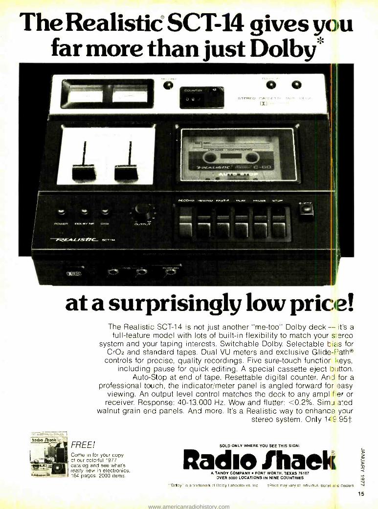
The Realistië SCT-14 gives you far more than just Dolby
7.59.1
at a surprisingly low price!
5,UG
#aác0lha Wc ._
The Realistic SCT -14 is not just another "me -too" Dolby deck -- its a full -feature model with lots of built -in flexibility to match your s areo
system and your taping interests. Switchable Dolby. Selectable hiLs for CrO2 and standard tapes. Dual VU meters and exclusive Glide -Path®
controls for precise, quality recordings. Five sure -touch functior keys, including pause for quick editing. A special cassette eject button.
Auto -Stop at end of tape. Resettable digital counter. Ani for a professional touch, the indicator /meter panel is angled forward for easy
viewing. An output level control matches the deck to any ampi fier or receiver. Response: 40- 13.000 Hz. Wow and flutter: <0.2 %. SimJlated
walnut grain end panels. And more. It's a Realistic way to enhance your stereo system. Only 1 L 9.95t
FREE! Come in for your copy of our colorful 1977 catalog and see what's really new in electronics. 164 pages. 2000 items.
SOLD ONLY WHERE YOU SEE THIS SIGN:
ftadue Ihae A TANDY COMPANY FORT WORTH, TEXAS 76107
OVER 5000 LOCATIONS IN NINE COUNTRIES
"Ddby' is a trademark of Dolby Laboratories. Inc. tPrice may vary at individ..al store: and cealers.
15
www.americanradiohistory.com
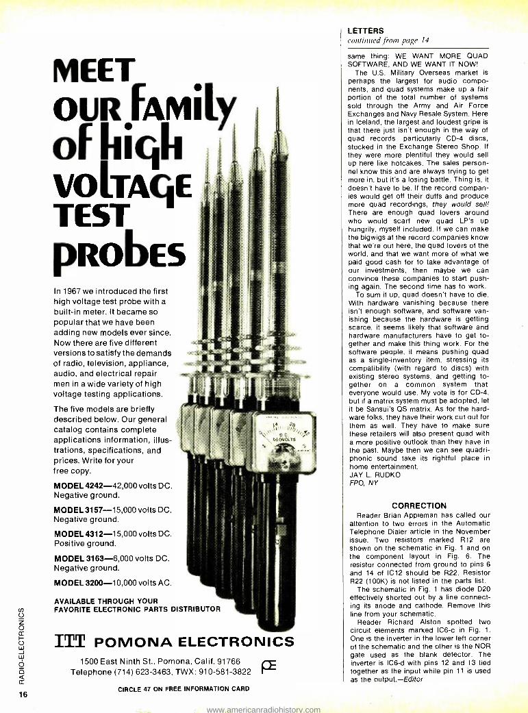
MEET OLJRFAMILy olhuqh VOLTAGE TEST PROBES In 1967 we introduced the first high voltage test probe with a
built -in meter. It became so popular that we have been adding new models ever since. Now there are five different versions to satisfy the demands of radio, television, appliance, audio, and electrical repair men in a wide variety of high voltage testing applications.
The five models are briefly described below. Our general catalog contains complete applications information, illus- trations, specifications, and prices. Write for your free copy.
MODEL 4242 -42,000 volts DC. Negative ground.
MODEL 3157 -15,000 volts DC. Negative ground.
MODEL 4312 -15.000 volts DC. Positive ground.
MODEL 3163 -6,000 volts DC. Negative ground.
MODEL 3200 -10,000 volts AC.
AVAILABLE THROUGH YOUR FAVORITE ELECTRONIC PARTS DISTRIBUTOR
ITT POMONA ELECTRONICS 1500 East Ninth St., Pomona, Calif. 91766
Telephone (714) 623 -3463, TWX: 910 -581 -3822
CIRCLE 47 ON FREE INFORMATION CARD
LETTERS continued from page 14
same thing: WE WANT MORE QUAD SOFTWARE, AND WE WANT IT NOW!
The U.S. Military Overseas market is
perhaps the largest for audio compo- nents, and quad systems make up a fair portion of the total number of systems sold through the Army and Air Force Exchanges and Navy Resale System. Here in Iceland, the largest and loudest gripe is that there just isn't enough in the way of quad records, particularly CD -4 discs, stocked in the Exchange Stereo Shop. If
they were more plentiful they would sell up here like hotcakes. The sales person- nel know this and are always trying to get more in, but it's a losing battle. Thing is, it doesn't have to be. If the record compan- ies would get off their duffs and produce more quad recordings, they would sell! There are enough quad lovers around who would scarf new quad LP's up hungrily, myself included. If we can make the bigwigs at the record companies know that we're out here, the quad lovers of the world, and that we want more of what we paid good cash for to take advantage of our investments, then maybe we can convince these companies to start push- ing again. The second time has to work.
To sum it up, quad doesn't have to die. With hardware vanishing because there isn't enough software, and software van- ishing because the hardware is getting scarce, it seems likely that software and hardware manufacturers have to get to- gether and make this thing work. For the software people, it means pushing quad as a single- inventory item, stressing its compatibility (with regard to discs) with existing stereo systems, and getting to- gether on a common system that everyone would use. My vote is for CD -4, but if a matrix system must be adopted, let it be Sansui's QS matrix. As for the hard- ware folks, they have their work cut out for them as well. They have to make sure these retailers will also present quad with a more positive outlook than they have in the past. Maybe then we can see quadri- phonic sound take its rightful place in home entertainment. JAY L. RUDKO FPO, NY
CORRECTION Reader Brian Appleman has called our
attention to two errors in the Automatic Telephone Dialer article in the November issue. Two resistors marked R12 are shown on the schematic in Fig. 1 and on the component layout in Fig. 6. The resistor connected from ground to pins 6
and 14 of IC12 should be R22. Resistor R22 (100K) is not listed in the parts list.
The schematic in Fig. 1 has diode D20 effectively shorted out by a line connect- ing its anode and cathode. Remove this line from your schematic.
Reader Richard Alston spotted two circuit elements marked IC6 -c in Fig. 1.
One is the inverter in the lower left corner of the schematic and the other is the NOR gate used as the blank detector. The inverter is IC6-d with pins 12 and 13 tied together as the input while pin 11 is used as the output.- Editor
www.americanradiohistory.com
P;11, THE NEW HEATHKIT CATALOG the worlds largest selection of fun -to- build, money - saving electronic kits!
VOM's & VTM's Electronics Service Instruments
Electronics Learning Programs Programmable Color TV Hi -Fi Components
Amateur Radio Radio Control Modeling Equipment Digital Clocks & Weather Accessories Marine, Auto & Aircraft Accessories
Read about the nearly 400 electronic kits you can build and service yourseif. The famous Heath assembly manua,s guide you every step of the way, and our quality design assures top performance from every kit you build.
Send for your copy today!
Heath Co., Dept. 20 -25 Benton Harbor, Michigan 49022
HEATH
Schlumberger
Please send me my FREE Heathkit Catalog. I am not on your mailing list.
IName
IAddress ' City State Zip
Heath Company, Dept. 20 -25 Benton Harbor, Michigan 49022
t- fi---- - - - - -- -.I CIRCLE 100 ON FREE INFORMATION CARD
www.americanradiohistory.com
The better the training the better you'll
COMPU -TRAINER
IN- CIRCUIT TRANSISTOR TESTER
TROUBLESHOOTER VOM
9'1
SOLID -STATE /
OSCILLOSCOPE
NTS /HEATH GR2000 Digital Solid -State Color TV 315 sq. in. Picture
l gis"=' -pl.
ELECTRO -LAB (Simulated TV Reception)
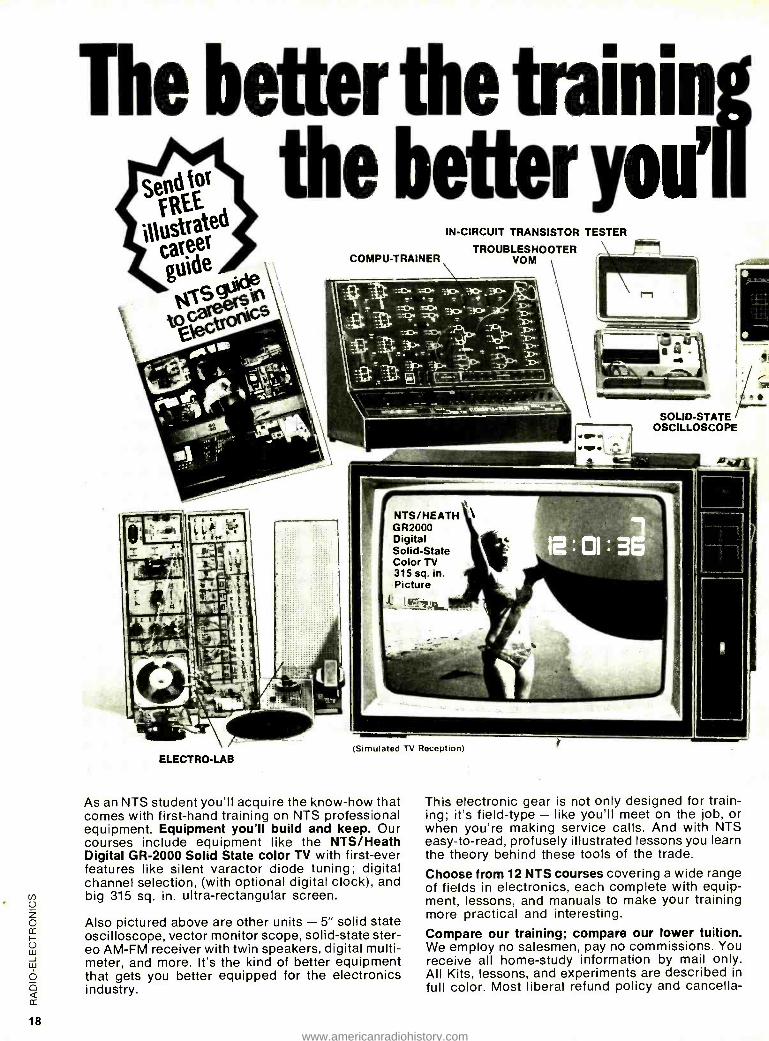
As an NTS student you'll acquire the know -how that comes with first -hand training on NTS professional equipment. Equipment you'll build and keep. Our courses include equipment like the NTS /Heath Digital GR -2000 Solid State color TV with first -ever features like silent varactor diode tuning; digital channel selection, (with optional digital clock), and big 315 sq. in. ultra -rectangular screen.
Also pictured above are other units - 5" solid state oscilloscope, vector monitor scope, solid -state ster- eo AM -FM receiver with twin speakers, digital multi - meter, and more. It's the kind of better equipment that gets you better equipped for the electronics industry.
This electronic gear is not only designed for train- ing; it's field -type - like you'll meet on the job, or when you're making service calls. And with NTS easy -to -read, profusely illustrated lessons you learn the theory behind these tools of the trade.
Choose from 12 NTS courses covering a wide range of fields in electronics, each complete with equip- ment, lessons, and manuals to make your training more practical and interesting.
Compare our training; compare our lower tuition. We employ no salesmen, pay no commissions. You receive all home -study information by mail only. All Kits, lessons, and experiments are described in full color. Most liberal refund policy and cancella-
www.americanradiohistory.com
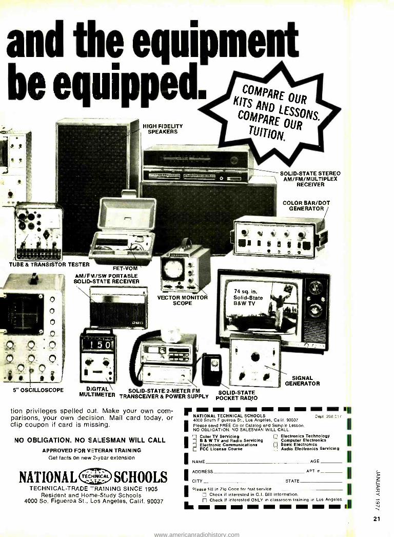
and the equipment be equipped.
Ili
HIGH FIDELITY SPEAKERS
SOLID -STATE STEREO AM/ FM/MULTIPLEX
RECEIVER
COLOR BAR /DOT GENERATOR
4P) ti II alai' TUBE & TRANSISTOR TESTER
FET -VOM AM /FN /SW PORTABLE SOLID -STATE RECEIVER
5" OSCILLOSCOPE
I +i' L VECTOR MONITOR
SCOPE
DL'GVTAL SOLID -STATE 2 -METER FM SOL D -STATE MULTIMETER TRANSCEIVER & POWER SUPPLY POCKET RADIO
u. r III =I um NE mw I II III III NATIONAL TECHNICAL SCHOOLS Dept 206 -017
I4000 South Figueroa St., Los Angeles, Calif. 90037
I Please send FREE Color Catalog and Sample Lesson. NO OBLIGATION. NO SALESMAN WILL CALL. I Color TV Servicing Electronics Technology
I B & W TV and Radio Servicing Computer Electronics Electronic Communications Basic Electronics FCC License Course Audio Electronics Servicing
INAME AGE I
tion privileges spelled oat. Make your own com- parisons, your own decision. Mail card today, or clip coupon if card is missing.
NO OBLIGATION. NO SALESMAN WILL CALL
APPROVED FOR VETERAN TRAINING Get facts on new 2 -year extension
NATIONAL TECHNICAL SCHOOLS TECHNICAL -TRADE TRAINING SINCE 1905
Resident and Home -Study Schools 4000 So. Figueroa St., Los Angeles, Calif. 90037
SIGNAL GENERATOR
IADDRESS APT x ' CITY STATE
I Please fill in Zip Code for fast service Check if interested in G.I. Bill information. Check if interested ONLY in classroom training in Los Angeles I. I MM MI - MI I- I= ME II'
21
www.americanradiohistory.com
The IMSAI 8080. A commercial yet personally affordable computer.
If you thought you could never afford a computer at home, think again. The IMSAI 8080 is built for rugged industrial performance.Yet its prices are competitive with Altair's hobbyist kit. Fully assembled, the 8080 is $931. Unassembled, it's $599.
The IMSAI 8080 is made for commercial users, and it looks it. Inside and out. The cabinet is attractive, heavy gauge aluminum. The heavy duty lucite front panel has an extra 8 program controlled LED's. It plugs directly into the Mother Board without a wire harness. And rugged commercial grade paddle switches are backed up by reliable debouncing circuits.
The system is optionally ex- pandable to a substantial system with 22 slots in a single printed circuit board. And the durable card cage is made of commercial -grade anodized aluminum.
The IMSAI 8080 power supply produces a true 28 amp current, enough to power a full system. You can expand to a powerful system with 64K of software protectable memory plus an intelligent floppy disk controller. You can add an audio tape cassette input device, a printer plus a video terminal and a teletype. And these peripherals will function with an 8 -level priority interrupt system. BASIC software is available in 4K, 8K and 12K.
Get a complete illustrated brochure describing the IMSAI 8080, options, peripherals, software, prices and specifications. end one dollar to cover handling to IMS. The IMSAI 8080. From the same technology that developed the HYPERCUBE Computer architecture and Intelligent Disk systems.
Dealer inquiries invited.
IMSAI Manufacturing Corp. 14860 Wicks Boulevard San Leandro, CA 94577 (415) 483 -2093 Dept. RE -1
CIRCLE 40 ON FREE INFORMATION CARD 22
iiU1PLITEF1 KORNER PAUL E. FIELD, DAVID G. LARSEN, PETER R. RONY, and JONATHAN A.
TITUS
II IIS ,MONTH. WE REI I. RN I IHE SEIMJL(I UI.
the substitution of software for hardware, i.e., the substitution of machine -level routines and subroutines for specific digital hardware devices that store, manipulate, transmit, or receive digital information. The hardware device that we will discuss is the universal asynchronous receiver transmitter, or UART --a 40 -pin integrated circuit that contains an independent 8 -bit asynchronous receiver and an independent 8 -hit asynchro- nous transmitter. Data rates range from DC to 60.000 bits per second. The receiver and transmitter sections of the IC can be programmed for 5, 6. 7, or 8 data hits; I or 2
stop bits; even or odd parity; and parity or no parity. The IC contains a variety of flags.
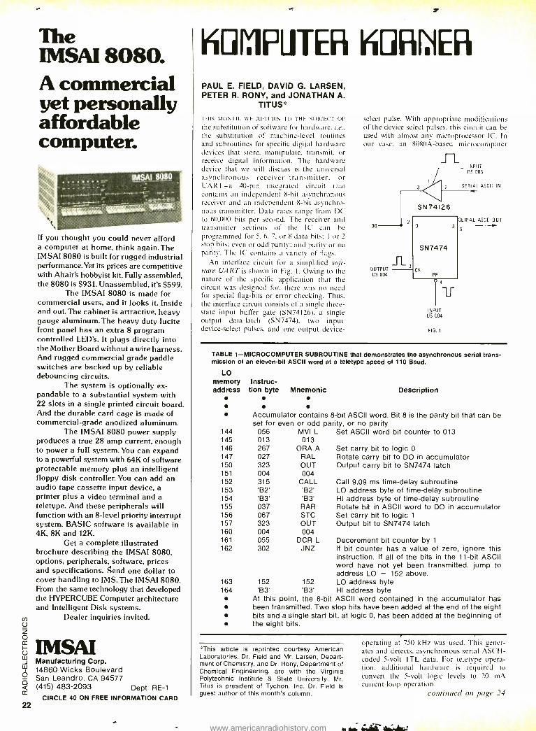
An interface circuit for a simplified soft- ware DART is shown in Fig. 1. Owing to the nature of the specific application that the circuit was designed for, there was no need for special flag -bits or error checking. Thus, the interface circuit consists of a single three - state input buffer gate (SN74I26). a single output data -latch (SN7474), two input device -select pulses, and one output device-
select pulse. With appropriate modifications of the device select pulses. this circuit can be used with almost any microprocessor IC. In our case, an 8080A -based microcomputer
DO
OUTPUT OS 004
INPUT DS 003
SERIAL ASCII IN
SN74126
SN7474
INPUT OS 004
FIG. 1
SERIAL ASCII OUT
5
TABLE 1- MICROCOMPUTER SUBROUTINE that demonstrates the asynchronous serial trans- mission of an eleven -bit ASCII word at a teletype speed of 110 Baud.
LO memory Instruc- address tion byte Mnemonic Description
Accumulator contains 8 -bit ASCII word. Bit 8 is the parity bit that can be set for even or odd parity, or no parity.
144 056 MVI L Set ASCII word bit counter to 013 145 013 013 146 267 ORA A Set carry bit to logic 0 147 027 RAL Rotate carry bit to DO in accumulator 150 323 OUT Output carry bit to SN7474 latch 151 004 004 152 315 CALL Call 9.09 ms time -delay subroutine 153 'B2' 'B2' LO address byte of time -delay subroutine 154 'B3' 'B3' HI address byte of time -delay subroutine 155 037 RAR Rotate bit in ASCII word to DO in accumulator 156 067 STC Set carry bit to logic 1
157 323 OUT Output bit to SN7474 latch 160 004 004 161 055 DCR L Decerement bit counter by 1
162 302 JNZ If bit counter has a value of zero, ignore this instruction. If all of the bits in the 11 -bit ASCII word have not yet been transmitted, jump to address LO = 152 above.
163 152 152 LO address byte 164 'B3' 'B3' HI address byte
At this point, the 8 -bit ASCII word contained in the accumulator has been transmitted. Two stop bits have been added at the end of the eight bits and a single start bit, at logic 0, has been added at the beginning of the eight bits.
This article is reprinted courtesy American Laboratories. Dr. Field and Mr. Larsen, Depart- ment of Chemistry, and Dr. Rony, Department of Chemical Engineering, are with the Virginia Polytechnic Institute & State University. Mr. Titus is president of Tychon, Inc. Dr. Field is guest author of this month's column.
operating at 750 kHz was used. This gener- ates and detects, asynchronous serial ASCH- coded 5 -volt TTL data. For teletype opera- tion. additional hardware is required to convert the 5 -volt logic levels to 20 mA current -loop operation.
continued on page 24
www.americanradiohistory.com
An Extraordinary Offer to introduce you to the benefits of Members
ELECTRONICS BOOK CL 706404 -9R Marepm- rMt11M ÑeMBN 16.16)
626,691-470 p -TWO BOOKS-Basic Electricity and Beginning Electronics 8 Eles Iron, :s Unraveled -A New Commonsense Approach 1517 90)
take any
of these unique electronics books (value to $611Q) for only
with a Trial Membership in the Book Club that quarante: save you 25% to 75% on a wide selection of electronics
All 2- and 3 -book sets count as
only one of your 3 Selections
Practkal Eiecu 0
000602 p -Master Handbook of 1001
Practical Electronic Circuits ($12.95)
....rá..,.'¡.á^
120 -210 p -Basic Digital Electronics
E. POLICE. /p.m)
SCAAngarn YON dal
son, .''~
035 -250 p -VHF/UHF Fire. Police. Ham Scanners Manual (59 95)
..`v;,, ÿ
ELECTRONIC CIRCf 1'' DESIh
HANDBO N
101 -416 p -Electronic C rc Handbook (517.95)
901 -448 p. -CET License Handbook 2nd Edition ($12.95)
919 -434 p. -Color TV Trouble Fast- ow- "" .. book -Problems 6 Solutions ($9.85)
E55 -666 p -Modem Electronics Matti ($12.95)
Beginner's Guide to
REPAIR
st -40
Cam.
467/729/780 -654 p -THREE 600KS -64 Hobby Prolecls tor Home and Car 8 RF
and Digital Test Equipment You Can : Build & 111 Digital and Linear IC Pro- ` jects ($25.85)
735 -294 p. -The Compi Radio Handbook ($9.95)
M 2-Way
INçTALLING TV ti FM ANTENNAS
Leo Ci Sands
561536-344 p -TWO BOOKS- Begin- ner's Goble t° TV Repair 8 Installing TV
and FM Anlannas (515.90)
627/672 -608 p. -TWO B00KS -8asic Electronic Test Procedures 8, Un- derstanding and Using the VOM 8' EVM
($17 -90) 748/S49.466 p. - TWO BOOKS -The Comslele Auto Electric Handbook 8 Auto Electronics Simplified ($17.90)
it 'FUSE TU ION
Og
582 -444 p- Commercial FCC License Handbook ($9.95)
abstitution
11 ay we send you your choice of these 3 practical. 1/1 time -and -money -saving books as part of an un- usual offer of a Trial Membership in Electronics Book Club?
Here are quality hardbound volumes, each especially designed to help you increase your know -how. earning power, and enjoyment of elec- tronics. Whatever your interest in electronics, you'll find Electronics Book Club offers practical. quality books that you can put to immediate use and benefit.
This extraordinary offer is intended to prove to you. through your own experience. that these very real advantages can be yours...that it is possible to keep up with the literature published in your areas of interest. and to save substantially while so do- ing. As part of your Trial Membership. you need purchase as few as four books during the coming 12
months. You would probably buy at least this many anyway...without the substantial savings offered through Club Membership.
To start your Membership on these attractive terms. simply fill out and mail the coupon today. You will receive the 3 books of your choice for 10-day inspection. YOU NEED SEND NO MONEY! If you are not delighted. return the books within 10
days and your Trial Membership will be cancelled without cost or obligation. ELECTRONICS BOOK CLUB, P.O. Box 10, Blue Ridge Summit, Pe. 17214
Facts About Club Membership The 3 introductory books of your choice carry publishers
retail prices of up to $61.70. They are yours for only 99e each (plus postage and handling) with your Trial Mem- bership.
You will receive the Club News. describing the current Selection. Alternates and other offerings. every 4 weeks (13 times a year).
If you want the Selection. do nothing: it will be sent to you automatically. O you do not wish to receive the Selection. or if you want to order one of the many Alternates offered. you simply give instructions on the reply form (and in the en- velope) provided, and return it to us by the date specified. This date allows you at least 10 days in which to return the form n. because of late mail delivery, you do not have 10 days to make a decision and so receive an unwanted Selec- tion. you may return it at Club expense.
Personal service for your account -no computers used! To complete your Trial Membership, you need buy only
four additional monthly selections or alternates during the next 12 months. You may cancel your Membership any time atter you purchase these four books.
All books- including the Introductory Offer -are fully re- turnable atter 10 days if you're not completely satisfied.
All books are offered at low Member prices, plus a small postage and handling charge. Prepaid orders shipped postpaid.
Continuing Bonus. If you continue after this Trial Mem- bership, you will earn a Dividend Certificate for every book you purchase. Three Certificates. plus payment of the nominal sum of $1.99, will entitle you to a valuable Book Oividend of your choice which you may choose from a list provided Members
CIRCLE 13 ON FREE INFORMATION CARD
I ELECTRONICS BOOK CLUB ' , , 1 1 1
1
! 1 ,
O
,
,
,
P.O. Box 10 Blue Ridge Summit, Pa. 17214
Please open my Trial Membership in ELEC -RONICS
BOOK CLUB and send me the 3 books circled below. I
understand the cost of the books I have selected is only 99c each, plus a small shipping charge. It not de- lighted, I may return the books within 10 days and owe
nothing. and have my Trial Membership t ar celled. I
agree to purchase at least four additional b3o s during the next 12 months, after which I may cancel 7y mem- bership at any time.
101 487 729780 628'691 563/6:16 582 627'672 655 728 735 748 "49 785 800 835 870 901 5'9
Name Phone
Address
City
State Zip_ (This otter valid for new Members only. Foreign and Canada a fc RE -17
23
www.americanradiohistory.com
To n Instruments, Citizens Band, BurglarAlarms, Automotive &
Nubby
Electronics! The more you know about electronics, the more you'll appreciate EICO. We have a wide range of products for you to choose from, each designed to provide you with the most pleasure and quality performance for your money. The fact that more than 3 million EICO products are in use attests to their quality and performance.
"Build -it- Yourself" and save up to 50% with our famous electronic kits.
For latest EICO Catalog and name of nearest EICO Distributor, check reader service card or send 500 for fast first class mail service.
EICO -283 Malta Street, Brooklyn, N.Y. 11207
Leadership in creative electronics since 1945.
KOMPUTER KORNER continued from page 22
Transmit subroutine The transmit subroutine, shown in Table I.
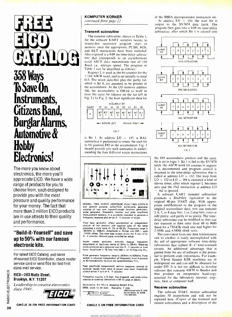
for the software UART occupies twenty to twenty -five successive program steps in memory once the appropriate PUSH, POP. and RET instructions have been included. Also required is a 9.09 ms time -delay subrou- tine that corresponds to an asynchronous serial ASCII data transmission rate of 110 Baud, i.e., teletype speed. The program in Table 1 can be described as follows:
Register L is used as the bit counter for the 11-bit ASCII word, and is set initially to octal 013. The seven data -bits plus the parity bit, which is Bit 8, are assumed to be present in the accumulator. At the LO memory address 146, the accumulator is OR'ed to itself to clear the carry bit (shown on the far left in Fig. 2.) In Fig. 2, the least significant data bit
CARRY
ACCUMULATOR
D7 D6 05 D4 03 D2 Dl 00
BIT 8
BIT 7
BIT 6
BIT 5
BIT 4
BIT 3
BIT 2
BIT 1
ROTATE LEFT
FIG.2
ROTATE RIGHT
is Bit 1. At address LO = 147, a RAL instruction is performed to rotate the start bit to bit position DO in the accumulator. Fig. 3
should provide you with assistance in under- standing the four different rotate instructions
[
it t T ,t t a MN QI'0,
*. 1?
MODEL 100A AUDIO RESPONSE PLOTTING SYSTEM and general purpose sweep /tone burst/pulse generator consists of two sine /square /triangle function generators, pulse generator, frequency counter and peak amplitude measurement sections. It is primarily intended to generate a
frequency response plot on an X - Y recorder or scope.
Time base generator offers symmetrical or independent control of the positive and negative sides of the ramp providing a duty cycle of .7% to 99.3 %. Frequency range is .0035Hz to 100kHz. Amplitude is 15Vpp into 500 0 with
5VDC offset. The time base output drives the X axis of an X - Y recorder. Manual mode provided for setup.
Audio sweep generator provides manual frequency adjustment or log /linear sweep of 20Hz to 20kHz. Blanking mode produces zero reference line onn X - Y recorder or tone burst. Amplitude is 15 Vpp into 500 Si or 10 Vpp into 80.
Pulse generator frequency range is .0035Hz to 525kHz. Pulse wideth is adjusted independent of frequency from 4 seconds to 40 nanoseconds. Outputs are complimentary TTL.
Peak amplitude measurement section measures internal or external signals from mike to power amp level. Amplitude output drives Y axis of X - Y recorder.
Frequency counter is 6 digit, line triggered, and reads either internal or external. Sensitivity is 50 my peak at 20kHz.
Dimensions: 8 x 14 x 3. Shipping Weight 9 lbs. $550, stock to 30 days. Warranty: 1 year.
1894 Commercenter W. #105
IDELIT1, SOUND San Bernardino, Ca 92408 17141 889-7623
CIRCLE 38 ON FREE INFORMATION CARD CIRCLE 5 ON FREE INFORMATION CARD
in the 8080A microprocessor instruction set. At address LO = 150, the start bit is
output to the SN7474 data latch. The program then goes into a 9.09 ms time -delay subroutine, after which Bit 1 is rotated into
CARRY BIT
7 6 5 4 3 2 o
RAR INSTRUCTION
CARRY BIT
7 6 5 4 3 2
Li Li Li Li RRC INSTRUCTION t
CARRY BIT 7 6 5 4 3 2
RAL INSTRUCTION
CARRY BIT 7
i-1 il f r 6 5 4 3 2 0
tJ t-J ll ZJ RLC INSTRUCTION
FIG.3
the DO accumulator position and the carry bit is set to logic 1. Bit 1 is fed to the SN7474 latch, the ASCII word bit counter in register L is decremented and program control is returned to the time -delay subroutine that is called at address LO = 152. The loop from LO = 152 to LO = 164 is executed a total of eleven times, after which register L becomes zero and the JNZ instruction at address LO = 162 is ignored.
A software UART transmit subroutine possesses a flexibility equivalent to the original 40 -pin UART chip. With appro- priate modifications to the program or the original accumulator data, you can transmit 5, 6, 7, or 8 data bits; 1 or 2 stop bits: even or odd parity; and parity or no parity. The time - delay subroutine can be modified so that you can transmit at data rates from 60 to 9600 Baud for a 750 -kHz clock rate and higher for 2 -MHz and 4 -MHz clock rates.
The conversion from one data transmission rate to another is easily accomplished with the aid of appropriate software time -delay subroutines that replace R -C time -constant circuits. An additional advantage that is gained from the use of software is the poten- tial to perform code conversions. For exam- ple, 5 -level Baudot KSR machines are in widespread use and can still be obtained for under $50. It is not too difficult to develop software that converts ASCII to Baudot and thus produce an inexpensive hard -copy terminal for the laboratory scientist, engi- neer, ham or computer buff.
Receive subroutine The software DART receive subroutine
requires 50 instructions and will not be repeated here. (Copies of the transmit and receive subroutines and a description of the
www.americanradiohistory.com
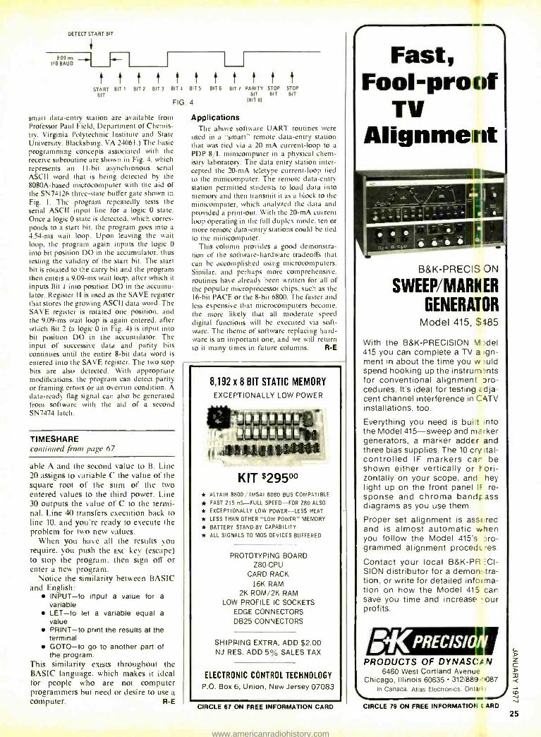
DETECT START BIT
9.09 uns - 110 BAUD
START BIT 1
BIT BIT 2 BIT 3
t BIT 4 BIT 5 BIT 6
FIG 4
smart data -entry station are available from Professor Paul Field. Department of Chemis- try. Virginia Polytechnic Institute and State University. Blacksburg. VA 24061.) The basic programming concepts associated with the receive subroutine are shown in Fig. 4. which represents an I1 -hit asynchronous serial ASCII word that is being detected by the 8080A -based microcomputer with the aid of the SN74126 three -state buffer gate shown in Fig. I. The program repeatedly tests the serial ASCII input line for a logic 0 state. Once a logic 0 state is detected. which corres- ponds to a start bit. the program goes into a
4.54 -ms wait loop. Upon leaving the wait loop, the program again inputs the logic 0
into bit position DO in the accumulator. thus testing the validity of the start bit. The start bit is rotated to the carry bit and the program then enters a 9.09 -ms wait loop. after which it inputs Bit I into position DO in the accumu- lator. Register H is used as the SAVE register that stores the growing ASCII data word. The SAVE register is rotated one position. and the 9.09 -ms wait loop is again entered, after which Bit 2 (a logic 0 in Fig. 4) is input into bit position DO in the accumulator. The input of successive data and parity bits continues until the entire 8 -bit data word is
entered into the SAVE register. The two stop bits are also detected. With appropriate modifications, the program can detect parity or framing errors or an overrun condition. A data -ready flag signal can also be generated from software with the aid of a second SN7474 latch.
TIMESHARE continued from page 67
able A and the second value to B. Line 20 assigns to variable C the value of the square root of the sum of the two entered values to the third power. Line 30 outputs the value of C to the termi- nal. Line 40 transfers execution back to line IO, and you're ready to execute the problem for two new values.
When you have all the results you require. you push the Esc key (escape) to stop the program. then sign off or enter a new program.
Notice the similarity between BASIC and English:
INPUT -to input a value for a variable LET -to let a variable equal a value PRINT -to print the results at the terminal GOTO -to go to another part of the program.
This similarity exists throughout the BASIC language. which makes it ideal for people who are not computer programmers but need or desire to use a
computer. R -E
I t t
BIT 7 PARITY STOP BIT BIT
IBIT 8)
t STOP BIT
Applications 7 he above software UART routines were
used in a "smart" remote data -entry station that was tied via a 20 mA current -loop to a
PDP 8/L minicomputer in a physical chem- istry laboratory. The data entry station inter- cepted the 20 -mA teletype current -loop tied to the minicomputer. The remote data -entry station permitted students to load data into memory and then transmit it as a block to the minicomputer. which analyzed the data and provided a print -out. With the 20 -mA current loop operating in the full duplex mode. ten or more remote data -entry stations could be tied to the minicomputer.
This column provides a good demonstra- tion of the software -hardware tradeoffs that can be accomplished using microcomputers. Similar. and perhaps more comprehensive. routines have already been written for all of the popular microprocessor chips. such as the 16 -bit PACE or the 8 -bit 6800. The faster and less expensive that microcomputers become. the more likely that all moderate speed digital functions will be executed via soft- ware. The theme of software replacing hard- ware is an important one, and we will return to it many times in future columns. R -E
8,192 x 8 BIT STATIC MEMORY
EXCEPTIONALLY LOW POWER
(t 441.141011411
KIT $29500 * ALTAIR 8800, IMSAI 8080 BUS COMPATIBLE
* FAST 215 nS -FULL SPEED -FOR Z80 ALSO
* EXCEPTIONALLY LOW POWER -LESS HEAT
* LESS THAN OTHER "LOW POWER" MEMORY
* BATTERY STAND-BY CAPABILITY
* ALL SIGNALS TO MOS DEVICES BUFFERED
PROTOTYPING BOARD Z80-CPU
CARD RACK 16K RAM
2K ROM /2K RAM LOW PROFILE IC SOCKETS
EDGE CONNECTORS DB25 CONNECTORS
SHIPPING EXTRA, ADD $2.00 NJ RES. ADD 5% SALES TAX
ELECTRONIC CONTROL TECHNOLOGY
P.O. Box 6, Union, New Jersey 07083
CIRCLE 67 ON FREE INFORMATION CARD
Fast, Fool -proof
TV Alignment
B &K- PRECIS CN
SWEEP /MARN ER
GENERATOR Model 415, $485
With the B &K- PRECISION VI -.del 415 you can complete a TV a gn- ment in about the time you w ;uId spend hooking up the instruni nts for conventional alignment pro- cedures. It's ideal for testing adja- cent channel interference in CAT`' installations, too.
Everything you need is built Into the Model 415 -sweep and marker generators, a marker adder and three bias supplies. The 10 cry ital- controlled IF markers car be shown either vertically or h ori- zontally on your scope, and hey light up on the front panel IF re- sponse and chroma bandFass diagrams as you use them.
Proper set alignment is asst red and is almost automatic when you follow the Model 415's pro- grammed alignment procedt. res
Contact your local B &K -PR =C1-
SION distributor for a demon: tra- tion, or write for detailed informa- tion on how the Model 415 car save you time and increase. ' our profits.
PRODUCTS OF DYNASC< N 6460 West Cortland Avenue
Chicago, Illinois 60635 312/889 -!1087 In Canada. Atlas Electronics. Ontor,
CIRCLE 79 ON FREE INFORMATION C ARD 25
www.americanradiohistory.com
THE MEAN LITTLE KIT
New compact 24 -piece kit of electronic tools for engineers, scientists, techni- cians, students, executives. Includes 7 sizes screwdrivers, adjustable wrench, 2 pair pliers, wire stripper, knife, 2 alignment tools, stainless rule, hex -key set, scissors, 2 flexible files, burnisher, miniature soldering iron, solder aid, coil of solder and desoldering braid. Highest quality padded zipper case, 6 x 9 x PA" inside. Satisfaction guaranteed. Send check, company purchase order or charge BankAmericard or Mastercharge. We pay the shipping charges. JTK -6 TOOL KIT
FREE CATALOG 128 pages of hard -to -find precision tools. Also con- tains 10 pages of useful "Tool Tips" to aid in tool selection. Send for your free copy today!
$60.00
J EN6EIV TOOZ..g .3343 &X,X.O6 4117 N. 44TH STREET, PHOENIX, ARIZONA 85018
CIRCLE 23 ON FREE INFORMATION CARD
equipment reports Heath AS -1344 2 -Way Column Speaker System Kit
CIRCLE 50 ON FREE INFORMATION CARD
THESE ARE THE NEWEST SPEAKERS IN THE Heathkit line. I was fortunate to get two units out of early production. They are 40 inches tall and I I inches square which lets them fit easily into almost any room. And the small size is especially important if you need four systems for quadriphonie sound. They are also tall enough so that the speakers them- selves, which are physically located in the top half of the cabinet. extend above any low - level obstructions such as coffee tables. lamps and the like that are common to the modern American home.
Each enclosure contains four speakers: two 6 -1r2 -inch woofers and two I -inch dome tweeters. The woofers handle 30 watts contin- uous. the tweeters, 20 watts continuous. Woofers and tweeters are fused separately (in pairs).
This system is truly a one evening project. All that has to be done is to assemble the crossover network and install the speakers. The cabinet itself is fully assembled and finished. It requires no work at all.
The diagram in Fig. I shows the schematic
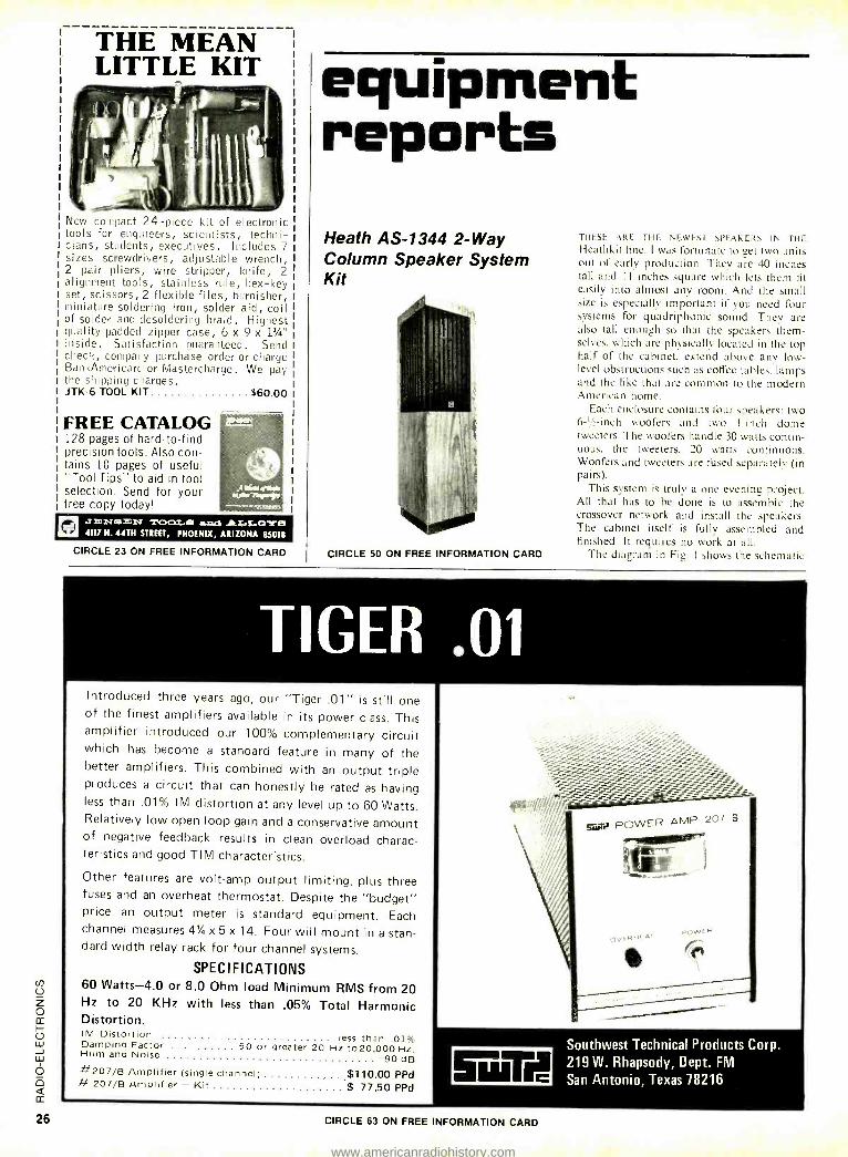
TIGER .01 Introduced three years ago, our "Tiger .01" is still one of the finest amplifiers available in its power class. This amplifier introduced our 100% complementary circuit which has become a standard feature in many of the better amplifiers. This combined with an output triple produces a circuit that can honestly be rated as having less than .01% IM distortion at any level up to 60 Watts. Relatively low open loop gain and a conservative amount of negative feedback results in clean overload charac- teristics and good TIM cháracteristics.
Other features are volt -amp output limiting, plus three fuses and an overheat thermostat. Despite the "budget" price an output meter is standard equipment. Each channel measures 41/4 x 5 x 14. Four will mount in a stan- dard width relay rack for four channel systems.
SPECIFICATIONS 60 Watts -4.0 or 8.0 Ohm load Minimum RMS from 20 Hz to 20 KHz with less than .05% Total Harmonic Distortion. IM Distortion less than .01% Damping Factor 50 or greater 20 Hz to20,000 Hz. Hum and Noise -90 dB #207/B Amplifier (single channel) $110.00 PPd # 207/B Amplifier - Kit $ 77.50 PPd
Southwest Technical Products Corp. 219 W. Rhapsody, Dept. FM
San Antonio, Texas 78216
CIRCLE 63 ON FREE INFORMATION CARD
www.americanradiohistory.com
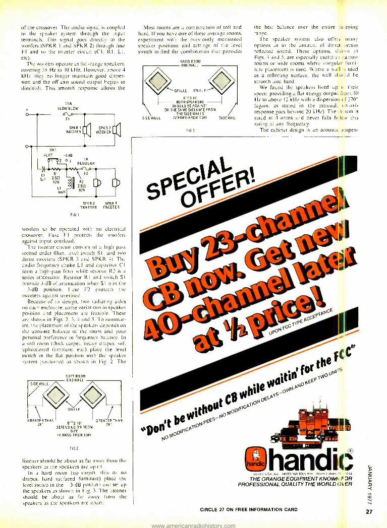
of the crossover. The audio signal is coupled to the speaker system through the input terminals. This signal goes directly to the woofers (SPKR 1 and SPKR 2) through fuse FI and to the tweeter circuit (C I. RI. LI. etc).
The woofers operate as full -range speakers. covering 35 Hz to IO kHz. However- above 4
kHz. they no longer maintain good disper- sion and the off axis sound output begins to diminish. This smooth response allows the
1'/:A
SLOW -BLOW
-3 dB
2 03 IA REGULAR
SPKR 3 SPKR 4
TWEETER TWEETER
FIG 1
woofers to be operated with no electrical crossover. Fuse F I protects the woofers against input overload.
The tweeter circuit consists of a high -pass second order filter, level switch SI. and two dome tweeters (SPKR 3 and SPKR 4). The audio frequency choke LI and capacitor Cl form a high -pass filter while resistor R2 is a series attenuator. Resistor RI and switch SI provide 3 -dB of attenuation when SI is in the -3 -dB position. Fuse F2 protects the tweeters against overload.
Because of its design, two radiating sides on each enclosure. some variations in speaker position and placement are feasible. These are shown in Figs. 2. 3. 4 and 5. To summar- ize. the placement of the speakers depends on the acoustic balance of the room and your personal preference in frequency balance. In a soft room (thick carpet. heavy drapes. soft upholstered furniture. etc.) place the level switch in the flat position with the speaker system positioned as shown in Fig. 2. The
SOFT ROOM END WALL
GREATER THAN 24" 6' TO 10'
GREATER THA
DEPENDING ON ROOM 24
SIZE (VIEWED FROM TOP)
FIG 2
listener should be about as far away from the speakers as the speakers are apart.
In a hard room (no carpet. thin or no drapes, hard surfaced furniture) place the level switch in the -3 -dB position and set up the speakers as shown in Fia. 3. The listener should be about as far away from the speakers as the speakers are apart.
Most rooms are a combination of soft and hard. If you have one of these average rooms, experiment with the previously mentioned speaker positions and settings of the level switch to find the combination that provides
HARD ROOM END WALL
GRILLE GRILLE
6'TO10' BOTH SPEAKERS
SHOULD BE AGAINST OR THE SAME DISTANCE FROM
THE SIDE WALLS (VIEWED FROM TOP) SIDE WALL SIDE WALL
FIG 3
the best balance over the entire -is.ening range.
The speaker system also offers many options as to the amount of direct ersus reflected sound. These options. sliovn in
Figs. 4 and 5. are especially useful in I arrow rooms or wide rooms where irregul ir furni- ture placement is used. Where a wal ú: used as a reflecting surface, the wall sl onld be smooth and hard.
We found the speakers lived up to their specs; providing a flat energy output from 50 Hz to above 12 kHz with a dispersion c f 270° (again, as stated in the manual. c n -axis response goes beyond 20 kHz). The .v tem is
rated at 4 ohms and never falls haicw this rating at any frequency.
The cabinet design is an acoustic sispen-
the , or th N,,s
. e wdtnNOKEEPr"
v I
0 C
bile
thdto MootFt_P
t aeGvitoNFEEs
14000 OtFt
9hEñdìò ande LISA le, 14510 NW 601h Ave Miami Lake =_ 1 .014
THE ORANGE EQUIPMENT KNOWN F 3R PROFESSIONAL QUALITY THE WORLD x )10 ER
CIRCLE 27 ON FREE INFORMATION CARD
www.americanradiohistory.com
lion type which has, of course, one limita- tion: it requires a relatively high -power amplifier. For normal operation a minimum
END WALL
GRILLE GRILLE GRILLE
NARROW ROOM OR WHERE SPEAKERS MUST BE PLACED
CLOSE TOGETHER
(VIEWED FROM TOP)
FIG 4
GRILLE
of 5 watts per channel is recommended. However, for a robust listening level you will need 15 to 25 watts per channel. Most of the
power is used in the low frequency range. This is the first place an amplifier will be overtaxed. If there is not enough power, you'll hear it as distorted sound, caused by clipping, on peaks in the music. If you use these speakers in a 15 by 20 -foot room with an 8 -foot ceiling (24.000 cu ft) and the room contains average furnishings, a peak power of 20 watts per channel into a pair of speakers will produce a sound field equivalent to 100 dB SPL (sound pressure level). This corres- ponds to the normal peak sound intensity produced by a large orchestra performing in a concert hall.
We connected the speaker system to our Heath Modulous control center and power amplifier. The response was amazingly good: clear. sharp and pleasant to listen to. Because of the height of the speakers above the floor we found it desirable to use the -3 -dB
More Power To You! Joint closer to cutters gives you this instead of this.
More cutting power with less effort. The plier pro- vides the "extra muscle." Perfectly mated cutters HOLD their edge. They're hand honed, scientifically heat treated. The joint is smooth working as a Swiss watch. Interfaces are precision machined. Drop forged, top quality steel. Beautiful full polished finish. Blue dipped plastic grips optional. Quality in every detail (at no premium in cost). CHANNEL - LOCK No. 369 Hi- Leverage Plier. Ask for it by name.
No. 369 Hi- Leverage Plier -9 Inch
Meet The Rest Of The Family ... Send For Our Free Catalog
CIRCLE 16 ON FREE INFORMATION CARD
position on the switch to limit what we considered excessive high frequency re- sponse. Since we have installed the speakers
END WALL
GRILLE
n SIDE WALL SIDE WALL-'
WIDE ROOM DR WHERE SPEAKERS MUST BE PLACED
FAR APART
(VIEWED FROM TOP)
ENO WALL
-"SIDE WALL SIDE WALL"' WIDE ROOM OR WHERE SPEAKERS
MUST BE PLACED FAR APART
(VIEWED FROM TOP)
FIG 5
several other people have listened to them and they seem to feel that it sounds Netter with the switch in the normal position. Perhaps our ears are tainted by prior listening habits. Assembly is really a cinch. The units sound great. look great. fit into almost any decor and are a worthwhile addi- tion to any hi -fi system. R -E
Sencore DVM -35 And DVM -36 Digital Multimeters
CIRCLE 80 ON FREE INFORMATION CARD
THE SENCORE PEOPLE ARE REALLY GOING D101-
tal in a big way. They now have a "set" of digital multimeters for all purposes. There are four models in all. The two in the middle are the DVM -35 and DVM -36. They look enough alike to be twins: both are built in the same portable compact cases made of Cycolac plastic. They say these can be dropped 10 feet to a cement floor without damage. I didn't have the intestinal fortitude to try this. but they look tough!
Despite the similarity, there are differ- ences. The DVM -35 has a 3 -digit readout with 1 k full -scale accuracy: Voltage scale are I. 10, 100. 1000 on AC or DC. For current, I. 10, 100 and 1000 mA, again both AC and DC.
The ability to read alternating current is one
www.americanradiohistory.com
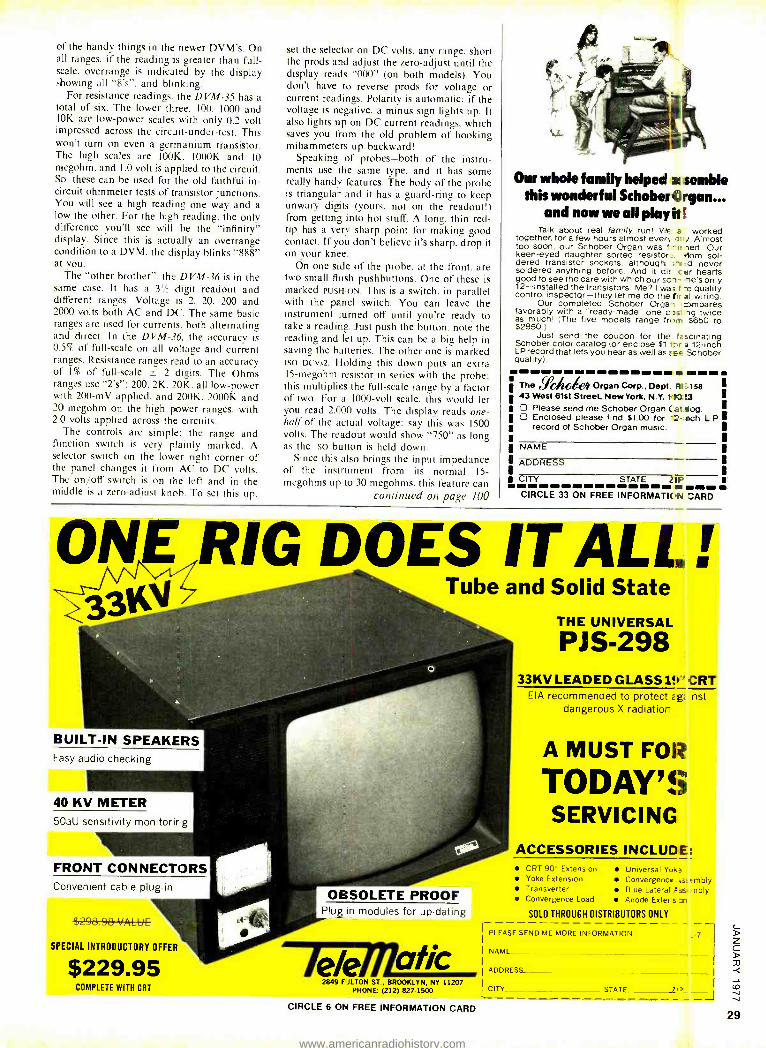
of the handy things in the newer DVM's. On all ranges, if the reading is greater than full - scale. overrange is indicated by the display showing all "8's ", and blinking.
For resistance readings, the DVM -35 has a total of six. The lower three. 100. 1000 and 10K are low -power scales with only 0.2 volt impressed across the circuit- under -test. This won't turn on even a germanium transistor. The high scales are 100K. 1000K and 10 megohm. and 1.0 volt is applied to the circuit. So. these can be used for the old faithful in- circuit ohmmeter tests of transistor junctions. You will see a high reading one way and a low the other. For the high reading, the only difference you'll see will be the "infinity" display. Since this is actually an overrange condition to a DVM, the display blinks "888" at you.
The "other brother ". the DVM -36 is in the same case. It has a 31/: digit readout and different ranges. Voltage is 2. 20, 200 and 2000 volts both AC and DC. The same basic ranges are used for currents, both alternating and direct. In the DVM -36. the accuracy is 0.5% of full -scale on all voltage and current ranges. Resistance ranges read to an accuracy of 1% of full -scale ± 2 digits. The Ohms ranges use "2's ": 200. 2K. 20K, all low -power with 200 -mV applied, and 200K. 2000K and 20 megohm on the high power ranges, with 2.0 volts applied across the circuits.
The controls are simple: the range and function switch is very plainly marked. A selector switch on the lower right corner of the panel changes it from AC to DC volts. The on /off switch is on the left and in the middle is a zero- adjust knob. To set this up,
set the selector on DC volts. any range, short the prods and adjust the zero -adjust until the display reads "000" (on both models). You don't have to reverse prods for voltage or current readings. Polarity is automatic: if the voltage is negative, a minus sign lights up. It also lights up on DC current readings, which saves you from the old problem of hooking miliammeters up backward!
Speaking of probes -both of the instru- ments use the same type, and it has some really handy features. The body of the probe is triangular and it has a guard -ring to keep unwary digits (yours. not on the readout!) from getting into hot stuff. A long. thin red - tip has a very sharp point for making good contact. If you don't believe it's sharp, drop it on your knee.
On one side of the probe. at the front. are two small flush pushbuttons. One of these is marked PUSH-ON. This is a switch. in parallel with the panel switch. You can leave the instrument turned off until you're ready to take a reading. Just push the button. note the reading and let up. This can be a big help in saving the batteries. The other one is marked Iso DCVx2. Holding this down puts an extra 15- megohm resistor in series with the probe: this multiplies the full -scale range by a factor of two. For a 1000 -volt scale, this would let you read 2.000 volts. The display reads one - half of the actual voltage: say this was 1500 volts. The readout would show "750" as long as the [so button is held down.
Since this also brings the input impedance of the instrument from its normal 15- megohms up to 30 megohms, this feature can
continued on page 100
Our whole family helped al4emble this wonderful Schober Organ...
and now we all play in Talk about real /amity fun! We a worked
together, for a few hours almost every i. Almost too soon, our Schober Organ was f - ied. Our keen -eyed daughter sorted resister, 1om sol- dered transistor sockets. although . -d never soldered anything before- And it die ' .ir hearts good to see the care with which our SC-I- -re's only 12- installed the transistors. Me? I was - e quality control inspector -they let me do the f ' al wiring.
Our completed Schober Orga' ampares favorably with a "ready- made" one c twice as much! (The five models range trio-. $650 to $2850.)
Just send the coupon for the fascinating Schober color catalog (or enclose $1 t:.r a 12 -inch LPrecord that lets you hear as well as see Schober quality).
The fidi,deh Organ Corp., Dept. R1 =158 ' 43 West 61st Street, New York, N.Y. 110. O Please send me Schober Organ Cat log. L Enclosed please find $1.00 for '2 -,ach L P.
record of Schober Organ music, I ' NAME
ADDRESS
CITY STATE 21P
CIRCLE 33 ON FREE INFORMATIIC +N CARD
ONE RIG DOES IT ALL. Tube and Solid State
BUILT -IN SPEAKERS Easy audio checking
40 KV METER 50aU sensitivity monitorirg
FRONT CONNECTORS Convenient cable plug -in
$208.08 VALUE
SPECIAL INTRODUCTORY OFFER
$229.95 COMPLETE WITH CRT
OBSOLETE PROOF Plug in modules for up- dating
lele fl/a/ic 2849 FJLTON ST.. BROOKLYN, NY 11207
PHONE (212) 827 -1500
THE UNIVERSAL
PJS -298
r
33KV LEADED GLASS 1!t" CRT EIA recommended to protect ¿gt nst
dangerous X- radiatior
A MUST FOR
TODAY'S SERVICING
ACCESSORIES INCLUDE: CRT 90' Extension Yoke Extension Transverter Convergence Load
Universal Yoke Convergence c sembly Blue Laterai AREA nbly Anode Eiters T
SOLD THROUGH DISTRIBUTORS ONLY
PLEASE SEND ME MORE INFORMATION
NAME
ADDRESS_ _
CITY_ _ STATE_
CIRCLE 6 ON FREE INFORMATION CARD 29
www.americanradiohistory.com
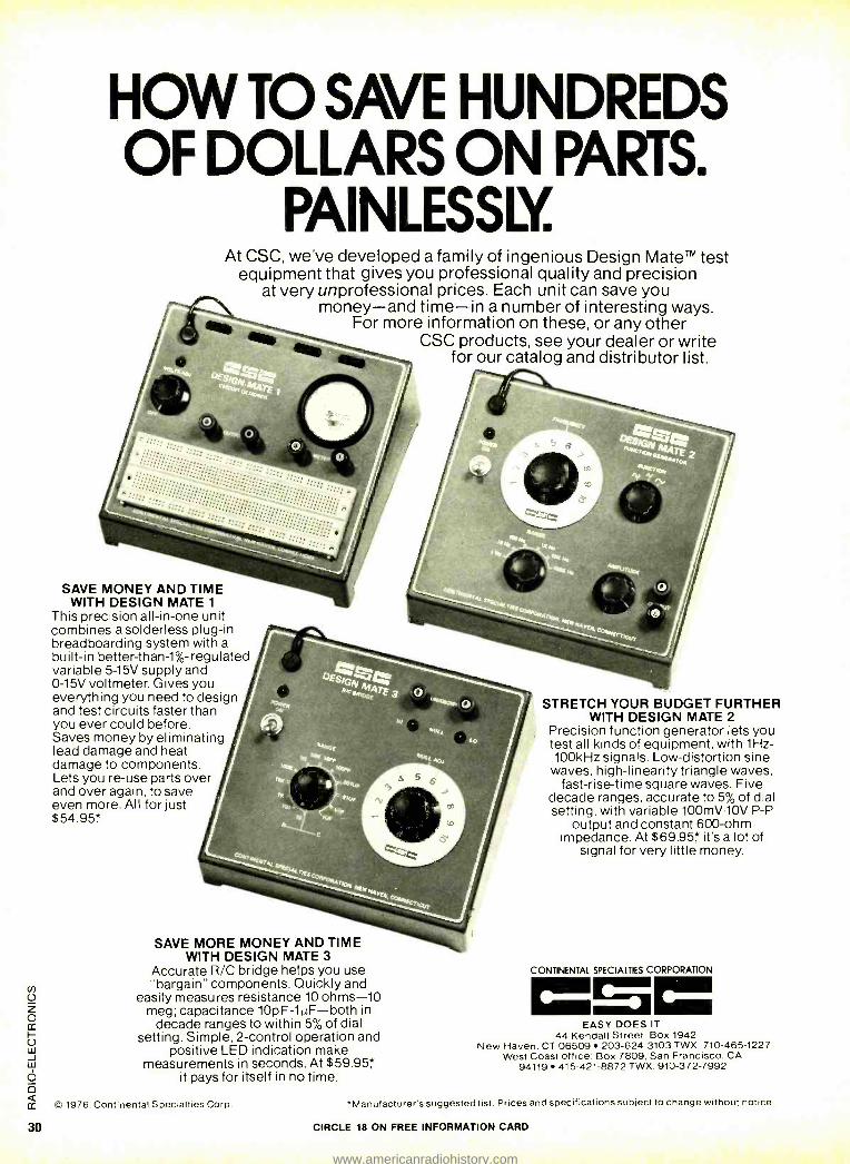
30
HOW TO SAVE HUNDREDS OF DOLLARS ON PARTS.
PAINLESSLY. At CSC, we've developed a family of ingenious Design Mate test
equipment that gives you professional quality and precision at very unprofessional prices. Each unit can save you
money -and time -in a number of interesting ways. For more information on these, or any other
CSC products, see your dealer or write for our catalog and distributor list.
SAVE MONEY AND TIME WITH DESIGN MATE 1
This precision all -in -one unit combines a solderless plug -in breadboarding system with a built -in better -than -1 %- regulated variable 5 -15V supply and 0 -15V voltmeter. Gives you everything you need to design and test circuits faster than you ever could before. Saves money by eliminating lead damage and heat damage to components. Lets you re -use parts over and over again, to save even more. All for just $54.95'.`
SAVE MORE MONEY AND TIME WITH DESIGN MATE 3
Accurate R/C bridge helps you use "bargain" components. Quickly and
easily measures resistance 10 ohms -10 meg; capacitance 10pF -1µF -both in
decade ranges to within 5% of dial setting. Simple, 2- control operation and
positive LED indication make measurements in seconds. At $59.95',`
it pays for itself in no time.
STRETCH YOUR BUDGET FURTHER WITH DESIGN MATE 2
Precision function generator lets you test all kinds of equipment, with 1Hz- 100kHz signals. Low- distortion sine
waves, high -linearity triangle waves, fast -rise -time square waves. Five
decade ranges, accurate to 5% of dial setting, with variable 100mV -10V P -P
output and constant 600 -ohm impedance. At $69.95 it's a lot of
signal for very little money.
CONTINENTAL SPECIALTIES CORPORATION =0= EASY DOES IT
44 Kendall Street. Box 1942 New Haven, CT 06509 203- 624 -3103 TWX. 710- 465 -1227
West Coast office Box 7809, San Francisco, CA 94119 415 -421 -8872 TWX: 910 -372 -7992
(C) 1976, Continental Specialties Corp. *Manufacturer's suggested list. Prices and specifications subject to change without notice.
CIRCLE 18 ON FREE INFORMATION CARD
www.americanradiohistory.com
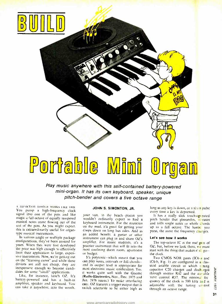
YfflTra'Ell 1111 ô Play music anywhere with this self -contained battery -powered
mini -organ. It has its own keyboard, speaker, unique pitch- bender and covers a five octave range
A TOP -OCTAVE DIVIDER WORKS LIKE THIS: You pump a high- frequency clock signal into one of the pins and like magic a full octave of equally tempered musical notes come flowing out of the rest of the pins. As you might expect, this is extraordinarily useful for organ - type musical instruments.
In various single or multiple package configurations, they've been around for years. When they were first developed the price was high enough to effectively limit their application to large, expen- sive instruments. Now, were getting out on the "learning curve" and while these devices are still not cheap, they are inexpensive enough to become candi- dates for some "small" applications.
Like, for instance, here's OZ. It's battery- powered and has a built -in amplifier, speaker and keyboard. You can take It anywhere; into the woods,
JOHN S. SIMONTON, JR.
your van, to the beach -places you wouldn't ordinarily expect to find a keyboard instrument. For the musician on the road, it's great for getting your chops down on long bus rides. And as an added benefit, a guitar or other instrument can plug in and share OZ's amplifier. For music students, it's a practice instrument that will fit into the most confining dorm room, apartment or budget.
It's polytonic -which means that you can play notes, intervals or full chords - and its output level is appropriate for most electronic music synthesizers. Yes, it works quite well with the Gnome (Radio -Electronics, Nov., Dec. 1975 and Jan. 1976 issues.) To make interfacing easy, OZ features a trigger output that is switch selectable to be either high as
long as any key is down, or a short pulse every time a key is depressed.
It has a really slick touch -cp rated pitch bender that glissandos, all oratos and trills single notes or whole words up to a full octave. The harcle you press, the more the frequency charges
Let's see how it works The top- octave IC is the real el is of
OZ; but, before we look there, ;Are must start with the thing that makes it in, go- the clock.
Two CMOS NOR gates (IC6 -a and IC6 -b, Fig. 1) are configured in a clas- sical astable circuit in which ti ping capacitor C20 charges and discl_..rges through resistor R42 and the v.w able TUNE control R57. The nominal fre- quency of the clock is 500 kHz as d is adjustable with the tuning c o 'trot through an octave range.
www.americanradiohistory.com
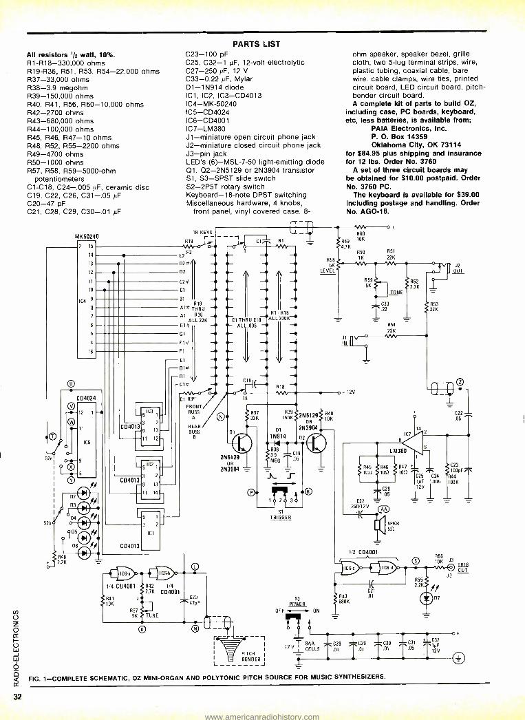
32
All resistors 1/2 watt, 10 %. R1 -R18- 330,000 ohms R19 -R36, R51, R53, R54- 22,000 ohms R37- 33,000 ohms R38 -3.9 megohm R39- 150,000 ohms R40, R41, R56, R60- 10,000 ohms R42 -2700 ohms R43- 680,000 ohms R44- 100,000 ohms R45, R46, R47 -10 ohms R48, R52, R55 -2200 ohms R49 -4700 ohms R50 -1000 ohms R57, R58, R59- 5000 -ohm
potentiometers C1 -C18, 024- .005 , F, ceramic disc C19, C22, C26, C31 -.05 jiF C20 -47 pF C21, C28, C29, C30 -.01 µF
MK50240
2 15
14
13
12
10
IC4 9
8
6
5
4
16
C 04024
41-
o- S2a o11-
12
11
9
6
IC5
- CD4013
5 IC3
3 2
9 13
11 12
CD4013
f
Si
3 2
9 13
11 14
C 04013
1/4 C04001
:R41 '10K
R57 5K
3 2
ICI
PARTS LIST C23 -100 pF C25, C32 -1 /IF, 12 -volt electrolytic C27- 250 µF, 12 V C33 -0.22 µF, Mylar D1 -1N914 diode IC1, IC2, IC3- CD4013 IC4 -MK -50240 IC5- CD4024 IC6- CD4001 IC7 -LM380 J1- miniature open circuit phone jack J2- miniature closed circuit phone jack J3 -pin jack LED's (6)- MSL -7 -50 light- emitting diode 01, Q2- 2N5129 or 2N3904 transistor S1, S3 -SPST slide switch S2 -2P5T rotary switch Keyboard -18 -note DPST switching Miscellaneous hardware, 4 knobs,
front panel, vinyl covered case, 8-
18 KEYS
,9,A1/9
E2 F2
D2#
D2
C2#
Cl
R19 A1# THRU Al R36
ALL 22K G1
G1
F1»
F1
01# D1 V
-C1?
C1 RY
FRONT BUSS
A
REAR BUSS
L
C6-6
942 1/4 2.7K
014/4001
_L. C20 47pF
TUNE
0
A
111-
111-
C- l THRU C18 41- ALL.005
R58 5K
LEVEL
ohm speaker, speaker bezel, grille cloth, two 5 -lug terminal strips, wire, plastic tubing, coaxial cable, bare wire, cable clamps, wire ties, printed circuit board, LED circuit board, pitch - bender circuit board. A complete kit of parts to build OZ,
including case, PC boards, keyboard, etc, less batteries, is available from;
PAIA Electronics, Inc. P. O. Box 14359 Oklahoma City, OK 73114
for $84.95 plus shipping and insurance for 12 lbs. Order No. 3760
A set of three circuit boards may be obtained for $10.00 postpaid. Order No. 3760 PC.
The keyboard is available for $39.00 including postage and handling. Order No. AGO -18.
R60
R49 10K
4.7K R 50
1K 22K
R51
H
V
C18
R1 R18 ALL 330K~
R59 5K
TONE
R52 2.2K
C33 R53 1.22 22K
R54
22 K
J2
OUT
IN
12V
18
R37 33 K
2N5129 OR
2N3904 -
r-
04'
01
R39. 150K:
1N914
R38 3.9 C19
MEG T _05
R40 10K
IC1
8
LM380
0 S1
TRIGGER
S3
POWER
OFF ON
T 8AA 12 V
,y PITCH I
BENDER J
C26
T .05
C27 _ = - - 250/12V
AA
R47 100,
C25
µF
12V
C22
05
C23
100pFi-. C24 R44 .005 100K
SPKR 8S2
1/2 C04001 R56 O 3 10K
710* SD
OUT J'3
I\
C21
R43 .01
680K
IC2B I C29
T.01 T0,
R55 2.2K
y C30 y C31 TD, T05
FIG. 1- COMPLETE SCHEMATIC, OZ MINI -ORGAN AND POLYTONIC PITCH SOURCE FOR MUSIC SYNTHESIZERS.
// 07
IC32 TlµF
12V
o+
www.americanradiohistory.com
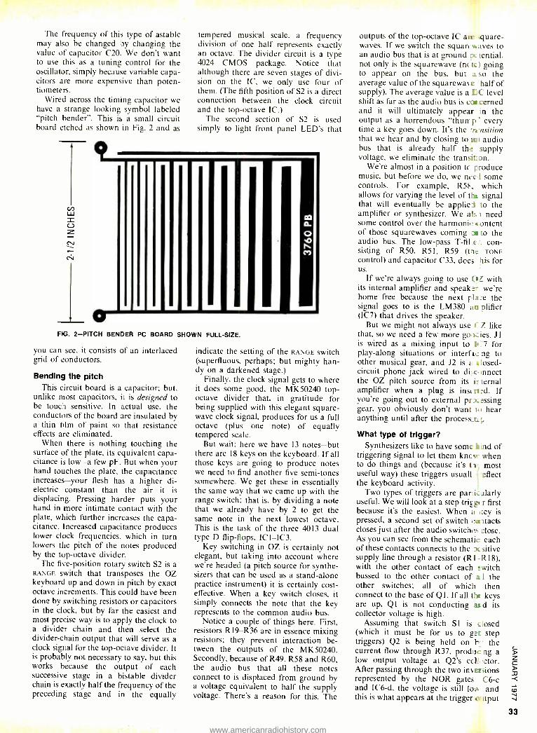
The frequency of this type of astable may also be changed by changing the value of capacitor C20. We don't want to use this as a tuning control for the oscillator, simply because variable capa- citors are more expensive than poten- tiometers.
Wired across the timing capacitor we have a strange looking symbol labeled "pitch bender ". This is a small circuit board etched as shown in Fig. 2 and as
9
o
tempered musical scale, a frequency division of one half represents exactly an octave. The divider circuit is a type 4024 CMOS package. Notice that although there are seven stages of divi- sion on the IC, we only use four of them. (The fifth position of S2 is a direct connection between the clock circuit and the top- octave IC.)
The second section of S2 is used simply to light front panel LED's that
O
co)
FIG. 2 -PITCH BENDER PC BOARD SHOWN FULL -SIZE.
you can see, it consists of an interlaced grid of conductors.
Bending the pitch This circuit board is a capacitor; but,
unlike most capacitors, it is designed to be touch sensitive. In actual use, the conductors of the board are insulated by a thin film of paint so that resistance effects are eliminated.
When there is nothing touching the surface of the plate, its equivalent capa- citance is low -a few pF. But when your hand touches the plate, the capacitance increases -your flesh has a higher di- electric constant than the air it is displacing. Pressing harder puts your hand in more intimate contact with the plate, which further increases the capa- citance. Increased capacitance produces lower clock frequencies, which in turn lowers the pitch of the notes produced by the top- octave divider.
The five- position rotary switch S2 is a RANGE switch that transposes the OZ keyboard up and down in pitch by exact octave increments. This could have been done by switching resistors or capacitors in the clock, but by far the easiest and most precise way is to apply the clock to a divider chain and then select the divider -chain output that will serve as a clock signal for the top -octave divider. It is probably not necessary to say, but this works because the output of each successive stage in a bistable divider chain is exactly half the frequency of the preceding stage and in the equally
indicate the setting of the RANGE switch (superfluous, perhaps; but mighty han- dy on a darkened stage.)
Finally, the clock signal gets to where it does some good, the MK50240 top - octave divider that. in gratitude for being supplied with this elegant square - wave clock signal, produces for us a full octave (plus one note) of equally tempered scale.
But wait; here we have 13 notes -but there are 18 keys on the keyboard. If all those keys are going to produce notes we need to find another five semi -tones somewhere. We get these in essentially the same way that we came up with the range switch; that is, by dividing a note that we already have by 2 to get the same note in the next lowest octave. This is the task of the three 4013 dual type D flip -flops, IC 1 -IC3.
Key switching in OZ is certainly not elegant, but taking into account where we're headed (a pitch source for synthe- sizers that can be used as a stand -alone practice instrument) it is certainly cost - effective. When a key switch closes, it simply connects the note that the key represents to the common audio bus.
Notice a couple of things here. First, resistors R19 -R36 are in essence mixing resistors; they prevent interaction be- tween the outputs of the MK50240. Secondly, because of R49, R58 and R60, the audio bus that all these notes connect to is displaced from ground by a voltage equivalent to half the supply voltage. There's a reason for this. The
outputs of the top- octave IC ate square - waves. If we switch the squat-.e ayes to an audio bus that is at ground pc tential, not only is the squarewave (nc tie) going to appear on the bus, but a so the average value of the squarewme 'half of supply). The average value is a EC level shift as far as the audio bus is coo cerned and it will ultimately appear in the output as a horrendous "shun- p every time a key goes down. It's the 'rensition that we hear and by closing to au audio bus that is already half the supply voltage, we eliminate the transition.
We're almost in a position tc produce music, but before we do, we nee I some controls. For example, R5 , which allows for varying the level of the signal that will eventually be applies to the amplifier or synthesizer. We afs) need some control over the harmonic: content of those squarewaves coming cm to the audio bus. The low -pass T -fil.e . con- sisting of R50. R51, R59 ant TONE control) and capacitor C33, doe; his for us.
If we're always going to use O? with its internal amplifier and speaker we're home free because the next plate the signal goes to is the LM380 an plifier (IC7) that drives the speaker.
But we might not always use C Z like that, so we need a few more gox ies. J1 is wired as a mixing input to I+ -7 for play -along situations or interf is ng to other musical gear, and J2 is z r losed- circuit phone jack wired to di :.r mnect the OZ pitch source from its it ternal amplifier when a plug is inst lied. If you're going out to external prxessing gear, you obviously don't want i.) hear anything until after the process ni ;.
What type of trigger? Synthesizers like to have some izind of
triggering signal to let them kncw when to do things and (because it's t le most useful way) these triggers usuall effect the keyboard activity.
Two types of triggers are park alarly useful. We will look at a step trim, r first because it's the easiest. When a Ivey is pressed, a second set of switch evritacts closes just after the audio switches close. As you can see from the schematic each of these contacts connects to the pir sitive supply line through a resistor (Rl -R18), with the other contact of each switch bussed to the other contact of a I the other switches; all of which then connect to the base of Q l . If all Lit keys are up, QI is not conducting aid its collector voltage is high.
Assuming that switch SI is closed (which it must be for us to get step triggers) Q2 is being held on tr the current flow through R37, proditc ng a low output voltage at Q2's colt, .ctor. After passing through the two inversions represented by the NOR gates C6 -c and IC6 -d, the voltage is still lo." and this is what appears at the trigger + tput
www.americanradiohistory.com
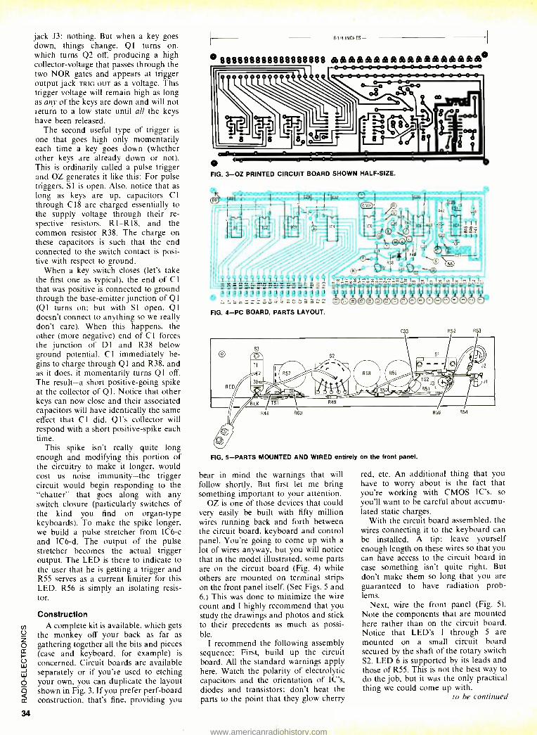
34
jack J3: nothing. But when a key goes down, things change. Q1 turns on, which turns Q2 off, producing a high collector -voltage that passes through the two NOR gates and appears at trigger output jack TRIG OUT as a voltage. This trigger voltage will remain high as long as any of the keys are down and will not return to a low state until all the keys have been released.
The second useful type of trigger is
one that goes high only momentarily each time a key goes down (whether other keys are already down or not). This is ordinarily called a pulse trigger and OZ generates it like this: For pulse triggers, SI is open. Also, notice that as long as keys are up, capacitors Cl through C18 are charged essentially to the supply voltage through their re- spective resistors, R1-R18, and the common resistor R38. The charge on these capacitors is such that the end connected to the switch contact is posi- tive with respect to ground.
When a key switch closes (let's take the first one as typical), the end of Cl that was positive is connected to ground through the base -emitter junction of Q1 (Q1 turns on; but with SI open, Q l
doesn't connect to anything so we really don't care). When this happens, the other (more negative) end of Cl forces the junction of D1 and R38 below ground potential. C 1 immediately be- gins to charge through Ql and R38, and as it does, it momentarily turns Q1 off. The result -a short positive -going spike at the collector of Ql. Notice that other keys can now close and their associated capacitors will have identically the same effect that C I did. Q l's collector will respond with a short positive -spike each time.
This spike isn't really quite long enough and modifying this portion of the circuitry to make it longer, would cost us noise immunity -the trigger circuit would begin responding to the "chatter" that goes along with any switch closure (particularly switches of the kind you find on organ -type keyboards). To make the spike longer, we build a pulse stretcher from IC6 -c and IC6 -d. The output of the pulse stretcher becomes the actual trigger output. The LED is there to indicate to the user that he is getting a trigger and R55 serves as a current limiter for this LED. R56 is simply an isolating resis- tor.
Construction A complete kit is available, which gets
the monkey off your back as far as gathering together all the bits and pieces (case and keyboard, for example) is
concerned. Circuit boards are available separately or if you're used to etching your own, you can duplicate the layout shown in Fig. 3. If you prefer perf -board construction, that's fine, providing you
8.1/4 INCHES
o 888888888888888888 óbóòólóséadòdDébóÒÓèóDéa6adòbò®6Ddb°
o FIG. 3 -OZ PRINTED CIRCUIT BOARD SHOWN HALF -SIZE.
I I I I I I I I I I l 1 1 I l 1 1 1
FIG. 4 -PC BOARD, PARTS LAYOUT.
, I I 42 -3,31 fl
IC51 C20 R1;
k® 0
R.37 ©33 I
C1I
I R40 1 , J`
R)8
ÏV 12.8)91 I L19OC2
Im1-ti
óóóóóóóóóáóóáóóóóóó
IC25
C31 1
R44 - 2F
I
822
C33
oQ S3
S2 --- v ! J2
R59 '-_ T52 t:I J341 Jl
E O ffi/, R 51 Jwo =uí- - -w = LK TS1 R49
R48 R60 R56 R54
R52 R53
FIG. 5 -PARTS MOUNTED AND WIRED entirely on the front panel.
bear in mind the warnings that will follow shortly. But first let me bring something important to your attention.
OZ is one of those devices that could very easily be built with fifty million wires running back and forth between the circuit board, keyboard and control panel. You're going to come up with a lot of wires anyway, but you will notice that in the model illustrated, some parts are on the circuit board (Fig. 4) while others are mounted on terminal strips on the front panel itself. (See Figs. 5 and 6.) This was done to minimize the wire count and I highly recommend that you study the drawings and photos and stick to their precedents as much as possi- ble.
I recommend the following assembly sequence: First, build up the circuit board. All the standard warnings apply here. Watch the polarity of electrolytic capacitors and the orientation of IC's, diodes and transistors; don't heat the parts to the point that they glow cherry
red, etc. An additional thing that you have to worry about is the fact that you're working with CMOS IC's, so you'll want to be careful about accumu- lated static charges.
With the circuit board assembled, the wires connecting it to the keyboard can be installed. A tip: leave yourself enough length on these wires so that you can have access to the circuit board in
case something isn't quite right. But don't make them so long that you are guaranteed to have radiation prob- lems.
Next, wire the front panel (Fig. 5). Note the components that are mounted here rather than on the circuit board. Notice that LED's 1 through 5 are mounted on a small circuit board secured by the shaft of the rotary switch S2. LED 6 is supported by its leads and those of R55. This is not the best way to do the job, but it was the only practical thing we could come up with.
to be continued
www.americanradiohistory.com
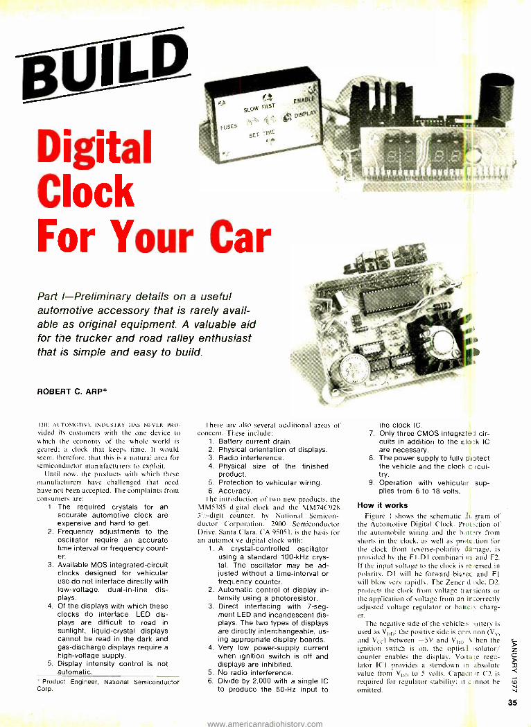
BUiLD Digital Clock For Your Car Part I- Preliminary details on a useful automotive accessory that is rarely avail- able as original equipment. A valuable aid for the trucker and road ralley enthusiast that is simple and easy to build.
ROBERT C. ARP*
THE AUTOMOTIVE INDUSTRY HAS NEVER PRO -
vided its customers with the one device to which the economy of the whole world is
geared; a clock that keeps time. It would seem. therefore. that this is a natural area for semiconductor manufacturers to exploit.
Until now, the products with which these manufacturers have challenged that need have not been accepted. The complaints from consumers are:
1. The required crystals for an accurate automotive clock are expensive and hard to get.
2. Frequency adjustments to the oscillator require an accurate time interval or frequency count- er.
3. Available MOS integrated- circuit clocks designed for vehicular use do not interface directly with low- voltage, dual -in -line dis- plays.
4. Of the displays with which these clocks do interface, LED dis- plays are difficult to read in sunlight, liquid -crystal displays cannot be read in the dark and gas- discharge displays require a high -voltage supply.
5. Display intensity control is not automatic.
* Product Engineer, National Semiconductor Corp.
There are also several additional areas of concern. These include:
1. Battery current drain. 2. Physical orientation of displays. 3. Radio interference. 4. Physical size of the finished
product. 5. Protection to vehicular wiring. 6. Accuracy.
The introduction of two new products. the MM5385 düeital clock and the MM74C928 3'/ -digit counter. by National Semicon- ductor Corporation. 2900 Semiconductor Drive. Santa Clara. CA 95051, is the basis for an automotve digital clock with:
1. A crystal -controlled oscillator using a standard 100 -kHz crys- tal. The oscillator may be ad- justed without a time -interval or frequency counter.
2. Automatic control of display in- tensity using a photoresistor.
3. Direct interfacing with 7 -seg- ment LED and incandescent dis- plays. The two types of displays are directly interchangeable, us- ing appropriate display boards.
4. Very low power -supply current when ignition switch is off and displays are inhibited.
5. No radio interference. 6. Divide by 2,000 with a single IC
to produce the 50 -Hz input to
the clock IC. 7. Only three CMOS integrate cir-
cuits in addition to the cla;k IC are necessary.
8. The power supply to fully protect the vehicle and the clock c rcui- try.
9. Operation with vehicular sup- plies from 6 to 18 volts.
How it works Figure I shows the schematic Ji. gram of
the Automotive Digital Clock. Prot tenon of the automobile wiring and the bait ry from shorts in the clock. as well as prette_tion for the clock from reverse -polarity .fanage, is provided by the FI -Dl combinati irk and F2. If the input voltage to the clock is re +erred in polarity. Dl will he forward- biarec and FI will blow very rapidly. The Zener d :tde. D2. protects the clock from voltage ttarsients or the application of voltage from an it orrectly adjusted voltage regulator or bane: y charg- er.
The negative side of the vehicles 'attery is
used as VDF): the positive side is cum non (Vss and Vcc) between -5V and V0,l) 'hen the ignition switch is on, the optict.1 isolator/ coupler enables the display. Vo, ta>e regu- lator ICI provides a stepdown rn absolute value from VD[) to 5 volts. Capacir r C2 is required for regulator stability; it e .nnot be omitted.
35
www.americanradiohistory.com
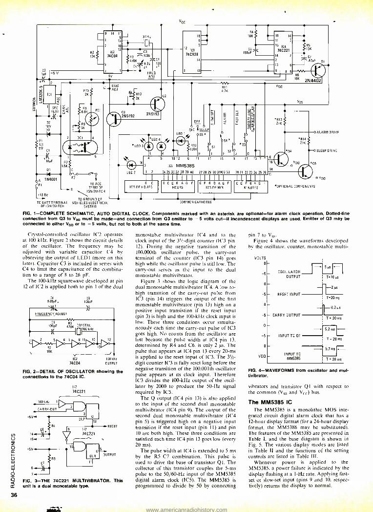
2
VCC
C2
1µF -5 V
R2
10K
v ICI -- _a á
1 SEE Y ó
TEXT ó a
02
+f- 18V 1W L l'
R1
1S2
5W Cl
A
F1
2
10NF R7
1.5K, 01
N 1N4001
+13.8V
9 14 11
8
13
10
12
6
5
74C04
-5V
BIAS L ADJ
XTAL
I1:11-
i. C3
R3 ^100pF 470K C5
9167'100 C4
pF pF
FRED -A131-
18 - 6-- 5 -
2 1c3
74C928
14
9 13
F2
B
TO BATT TERMINAL OF IGN SWITCH
o-q
TO ACC TERM OF
IGN SWITCH
®S R10
2K
2N 5192
TO GROUND OF
VEHICLES ELECTRICAL SYSTEM
2N 51 93
* LED 3
*LEO 4
LED
w 811 4.7K
OFF
O Q0 O w
SEC }SLEEP,
óS5
R12 100K
LED 2
3
18 12 6
IC5 MM5385
1 S1
H pl
11 l0 15
á
o
S4*
52
1 2 -34 35 38 31 38 39 40 27 28 29 30 31)32 33
8 C
10'613E HOURS
54 10K
C6
10 16
3
15 IC4
74C22
R5
10K 150pF
14 1 C7
2 .47yF a 13 6
9 1 B 5
86 \+ DK 2N4402
V
VSS
*R13' LL 27K
lo ALARM DRIVE
.R14
0 *SI) 27K
I D Q4 SLEEP DRIVE
9 17 1
E
16 VOD 5
14 20 21 22 23 24 25 26 IIIIIII IIIIIII IIIIIII
E C O B A G F C E B O A G F
HOURS 10'5OFMIN C D E R A S F
MINUTES
COMMON CATHODES
*OPTIONAL COMPONENTS
Vo0
RG. 1- COMPLETE SCHEMATIC, AUTO DIGITAL CLOCK. Components marked with an asterisk are optional -for alarm clock operation. Dotted -line connection from 03 to VDD must be made -and connection from 03 emitter to -5 volts cut -if incandescent displays are used. Emitter of 03 may be connected to either VDD or to 5 volts, but not to both at the same time.
Crystal- controlled oscillator 1C2 operates at 100 kHz. Figure 2 shows the circuit details of the oscillator. The frequency may be adjusted with variable capacitor C4 by observing the output of LED I (more on this later). Capacitor C3 is included in series with C4 to limit the capacitance of the combina- tion to a range of 8 to 26 pF.
The 100 -kHz squarewave developed at pin 12 of IC2 is applied both to pin 1 of the dual
C4
9-35pF.
VIT
C3
100pF
my - A FREQUENCY ADJUST
%%
100pF 470K CRYSTAL
1DDLHz
1 2 5 6 9 8 111 10 12
R2 13
10K
V IC2 100 kHz
74C04 OUTPUT
FIG. 2- DETAIL OF OSCILLATOR showing the connections to the 74C04 IC.
12 74C221
100 kHz 1
CARRY -OUT 2
3 5V
C6 14 15--
+5V
6
7..
R4
CLR 13
fl
1/2
74C221
_D a
CLR
RESET
5y OUTPUT
FIG. 3 -THE 74C221 MULTIVIBRATOR. This unit is a dual monostable type.
monostable multivibrator IC4 and to the clock input of the 31/2,-digit counter (IC3 pin 12). During the negative transition of the 100.000th oscillator pulse. the carry -out terminal of the counter (1C3 pin 14) goes high while the oscillator pulse is still low. The carry -out serves as the input to the dual monostable multivibrator.
Figure 3 shows the logic diagram of the dual monostable multivibrator IC4. A low -to- high transition of the carry -out pulse from IC3 (pin 14) triggers the output of the first monostable multivibrator (pin 13) high on a
positive input transistion if the reset input (pin 3) is high and the 100 -kHz clock input is
low. These three conditions occur simulta- neously each time the carry-out pulse of 1C3 goes high. No counts from the oscillator are lost because the pulse width at IC4 pin 13.
determined by R4 and C6, is only 2 µs. The pulse that appears at IC4 pin 13 every 20 -ms is applied to the reset input of IC3. The 3'/2-
digit counter IC3 is fully reset long before the negative transition of the IOO,001th oscillator pulse appears at its clock input. Therefore IC3 divides the 100 -kHz output of the oscil- lator by 2000 to produce the 50 -Hz signal required by IC5.
The Q output (IC4 pin 13) is also applied to the input of the second dual monostable multivibrator (IC4 pin 9). The output of the second dual monostable multivibrator (1C4 pin 5) is triggered high on a negative input transition if the reset input (pin 11) and pin 10 are both high. These three conditions are satisfied each time IC4 pin 13 goes low (every 20 ms).
The pulse width at 1C4 is extended to 5 ms by the R5-C7 combination. This pulse is used to drive the base of transistor Q1. The collector of this transistor couples the 5 -ms pulse to the 50 /60 -Hz input of the MM5385 digital alarm clock (IC5). The MM5385 is
programmed to divide by 50 by connecting
pin 7 to Vss.
Figure 4 shows the waveforms developed by the oscillator, counter. monostable multi-
VOLTS
0
-5
0
-5
D
-5
0
-5
0
VOO
5µs
OSCILLATOR OUTPUT T =10 µs
RESET INPUT
- CARRY OUTPUT
INPUT TO 0.1
INPUT TO MM5385
--2 µs
T=20 ms
1-0.2µs
T = 20 ms
5.2msL
T = 20 ms
5.7 ms
T = 20 ms
FIG. 4- WAVEFORMS from oscillator and mul- tivibrator.
vibrators and transistor Q l with respect to the common (Vss and Vcc) bus.
The MM5385 IC The MM5385 is a monolithic MOS inte-
grated circuit digital alarm clock that has a
12 -hour display format (for a 24 -hour display format. the MM5386 may be substituted). The features of the MM5385 are presented in Table I, and the base diagram is shown in Fig. 5. The various display modes are listed in Table II and the functions of the setting controls are listed in Table III.
Whenever power is applied to the MM5385, a power failure is indicated by the display flashing at a 1 -Hz rate. Applying fast - set or slow -set input (pins 9 and 10, respec- tively) returns the display to normal.
www.americanradiohistory.com
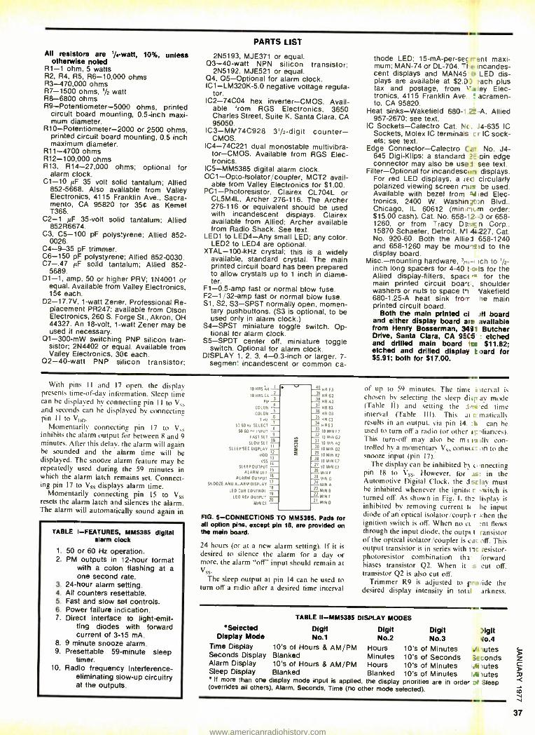
All resistors are 1/4-watt, 10%, unless otherwise noted
R1 -1 ohm, 5 watts R2, R4, R5, R6- 10,000 ohms R3- 470,000 ohms R7 -1500 ohms, 1/2 watt R8 -6800 ohms R9- Potentiometer -5000 ohms, printed
circuit board mounting, 0.5 -inch maxi- mum diameter.
R10- Potentiometer -2000 or 2500 ohms, printed circuit board mounting, 0.5 inch maximum diameter.
R11 -4700 ohms R12- 100,000 ohms R13, R14- 27,000 ohms; optional for
alarm clock. C1 -10 ILF 35 volt solid tantalum; Allied
852 -5668. Also available from Valley Electronics, 4115 Franklin Ave., Sacra- mento, CA 95820 tor 35C as Kemet T366.
C2 -1 pF 35 -volt solid tantalum; Allied 852R6674.
C3, C5 -100 pF polystyrene; Allied 852- 0026.
C4 -9-35 pF trimmer. C6 -150 pF polystyrene; Allied 852 -0030. C7 -.47 µF solid tantalum; Allied 852-
5689. D1 -1, amp, 50 or higher PRV; 1N4001 or
equal. Available from Valley Electronics, 15¢ each.
D2- 17.7V, 1 -watt Zener, Professional Re- placement PR247; available from Olson Electronics, 260 S. Forge St.. Akron. OH 44327. An 18 -volt, 1 -watt Zener may be used if necessary.
01- 300 -mW switching PNP silicon tran- sistor; 2N4402 or equal. Available from Valley Electronics, 30¢ each.
02 -40 -watt PNP silicon transistor;
PARTS LIST
2N5193, MJE371 or equal. 03 -40 -watt NPN silicon transistor:
2N5192, MJE521 or equal. Q4, 05- Optional for alarm clock. ICI- LM320K -5.0 negative voltage regula-
tor. IC2 -74004 hex inverter -CMOS. Avail-
able `rom RGS Electronics, 3650 Charles Street. Suite K. Santa Clara, CA 95050.
IC3- MM74C928 31/2 -digit counter - CMOS.
IC4- 74C221 dual monostable multivibra- tor-CMOS. Available from RGS Elec- tronics.
IC5- MM5385 digital alarm clock. 0C1-Op:o- Isolator /coupler, MCT2 avail-
able from Valley Electronics for $1.00. PC1- Phctoresistor. Clairex CL704L or
CL5M4L. Archer 276 -116. The Archer 276 -116 or equivalent should be used with incandescent displays. Clairex available from Allied: Archer available from Radio Shack. See text.
LED1 to LED4 -Any small LED: any color. LED2 to LED4 are optional.
XTAL -100 -kHz crystal: this is a widely available, standard crystal. The main printed circuit board has been prepared to allow crystals up to 1 inch in diame- ter.
F1 -0.5 -amp fast or normal blow fuse. F2 -1 /32 -amp fast or normal blow fuse. S1, S2, S3 -SPST normally open. momen-
tary pushbuttons. (S3 is optional, to be used orly in alarm clock.)
S4 -SPST miniature toggle switch. Op- tional for alarm clock.
S5 -SPDT center off, miniature toggle switch. Optional for alarm clock.
DISPLAY 1. 2. 3. 4 -0.3 -inch or larger. 7- segment incandescent or common ca-
.11
thode
a-
thode LED; 15 -mA- per -set r -ant maxi- mum: MAN -74 or DL -704. -Ì e Incandes- cent displays and MAN45 tr LED dis- plays are available at $2.0) each plus tax and postage. from t'aley Elec- tronics. 4115 Franklin Ave _ acramen- to. CA 95820.
Heat sinks -Wakefield 680- -.2` -A, Allied 957 -2670; see text.
IC Sockets -Calectro Cat. Rlc . J4 -635 IC Sockets, Molex IC terminais c r IC sock- ets: see text.
Edge Connector -Calectro CG--t No. J4- 645 Digi -Klips: a standard ?-.7:-din edge connector may also be use i see text.
Filter- Optional for incandescon displays. For red LED displays. a rEC circularly polarized viewing screen nos be used. Available with bezel from AJ led Elec- tronics. 2400 W. Washin3t)n Blvd.. Chicago, IL 60612 (min ri -m order: $15.00 cash). Cat. No. 658 -12.0 or 658- 1260, or from 'racy Da!;icn Corp.. 15870 Schaefer, Detroit, MI 4227, Cat. No 920 -60. Both the Allies 658 -1240 and 658 -1260 may be mot'rt?d to the display board.
Misc.- mounting hardware. ' - ich to 1/2- inch long spacers for 4 -40 t a is for the Allied display -filters. space r_ for the main printed circuit boa-c, shoulder washers or nuts to space th a Vakefield 680 -1.25 -A heat sink froT he main printed circuit board.
Both the main printed ci-cu t board and either display board are available from Henry Bosserman, 3431 Butcher Drive, Santa Clara, CA 9E(6 : etched and drilled main board la $11.82; etched and drilled display t oard for $5.91; both for $17.00.
With pins I I and 17 open. the display presents time -of -day infb-mation. Sleep time can he displayed by connecting pin II to V and seconds can he displayed by connecting pin 11 to Vnll
Momentarily connecting pin 17 to V inhibits the alarm output for between 8 and 9 minutes. After this delay. the alarm will again be sounded and the alarm time will be displayed. The snooze alarm feature may he repeatedly used during :he 59 minutes in which the alarm latch remains set. Connect- ing pin 17 to Vss displays alarm time.
Momentarily connecting pin 15 to Vss resets the alarm latch and silences the alarm. The alarm will automatically sound again in
TABLE I- FEATURES, MM5385 digital alarm clock
1. 50 or 60 Hz operation. 2. PM outputs in 12 -hour format
with a colon flashing at a one second rate.
3. 24 -hour alarm setting. 4. All counters resettable. 5. Fast and slow set controls. 6. Power failure indication. 7. Direct interface to light -emit -
ting diodes with forward current of 3 -15 mA.
8. 9 minute snooze alarm. 9. Presettable 59- minute sleep
timer. 10. Radio frequency interference -
eliminating slow -up circuitry at the outputs.
10 HRS44
1OURS CO
PM
COLON
COLON
H:
5) 60 Ht SELECT
50 60 Ht INPUT
FAST SET
SLOW SET
SLEEP'SEC DISPLAY
VOO
VSs
SLEEP OUTPUT
ALARM OFF ALARM OUTPUT
SNOOZE AND A.ARM DISPLAY 17
LEO CUR CONTROL 19
LEO REF OUTPUT 20
MINCI
. 40
39
38
37
36
NR 13
HR 53
RH A3
HR 63
HR 03 35 HR C3 34 HR E7 37
10 MIN F2 32
10 MIN G2 31
10 MINA) 30
10 MIN 02
29 10 MIN Bi 1B
IO MIN E7
27 10 MIN C2 26
RIN F
25
24 MIN
MIN A 23
MIN B 22
MIN 21 MIN D
FIG. 5- CONNECTIONS TO MM5385. Pads for all option pi's, except pin 18, are provided on the main board.
24 hours (o- at a new alarm setting). If it is desired to silence the alarm for a day or more. the alum "off' input should remain at Vss.
The sleep output at pin 14 can he used to turn off a radio after a desired time interval
of up to 59 minutes. The tinte _ tergal is chosen by selecting the sleep di;h iv mode (Table Ili and setting the J -i -ed tinte interval (Table Ill). This ai I maticall results in an output. via pin 14 :nit can he used to turn off a radio (or other E- ,liancesl. This turn -off may also he mttv:Ils con- trolled by a momentary Vs, connes_ on to the snooze input (pin 171.
'The display can he inhibited FA e nnecting pin 18 to Vs.. However. for a.. in the Automotive Digital Clock. the .1'.- lay must he inhibited whenever the igniut r 'witch is turned oft'. As shown in Fig. 1. the lisplay is inhibited by removing current It he input diode of an optical isolator courut r when the ignition switch is ofT. When no ci runt flows through the input diode. the outfit t ransistor of the optical isolator coupler is ci Of. This output transistor is in series with ti_ resistor - photoresistor combination tht !brward biases transistor Q2. When it s cut off. transistor Q2 is also cut off.
Trimmer R9 is adjusted to f7-.ß ide the desired display intensity in total ..rkness.
ARNO
TABLE II- MM5385 DISPLAY MODES
*Selected Digit Digit Digit )Igit Display Mode No.1 No.2 No.3 Vo,4
Time Display 10's of Hours & AM /PM Hours 10's of Minutes ¿i lutes Seconds Display Blanked Minutes 10's of Seconds îeconds Alarm Display 10's of Hours & AM /PM Hours 10's of Minutes rfilutes Sleep Display Blanked Blanked 10's of Minutes A)utes ' If more :han one display mode input is applied, the display priorities are in orde- De Sleep (overrides all others), Alarm, Seconds. Time (no other mode selected).
OEM
www.americanradiohistory.com
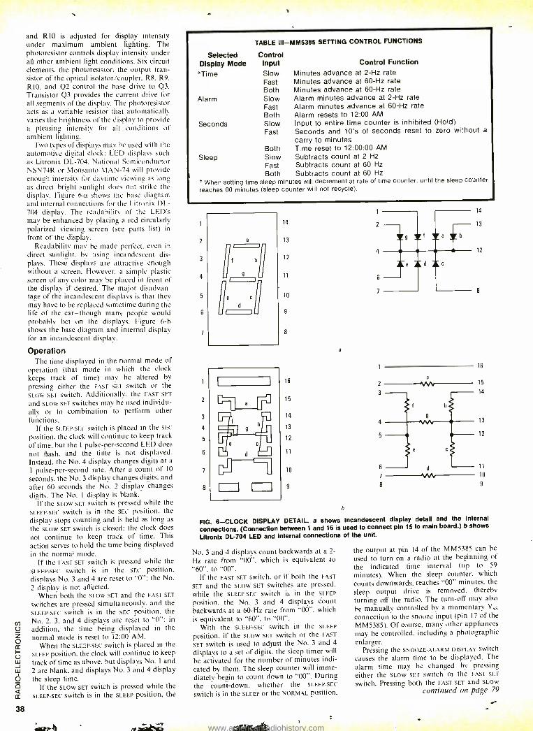
and RIO is adjusted for display intensity under maximum ambient lighting. The photoresistor controls display intensity under all other ambient light conditions. Six circuit elements, the photoresistor, the output tran- sistor of the optical isolator /coupler, R8, R9, R10. and Q2 control the base drive to Q3. Transistor Q3 provides the current drive for all segments of the display. The photoresistor acts as a variable resistor that automatically varies the brightness of the display to provide a pleasing intensity for all conditions of ambient lighting.
Two types of displays may he used with the automotive digital clock: LED displays such as Litronix DL -704. National Semiconductor NSN74R or Monsanto MAN -74 will provide enough intensity for daytime viewing as long as direct bright sunlight does not strike the display. Figure 6 -a shows the hase diagram and internal connections for the Litronix DL- 704 display. The readability of the LED's may be enhanced by placing a red circularly polarized viewing screen (see parts list) in front of the display.
Readability may be made perfect. even in direct sunlight. by using incandescent dis- plays. These displays are attractive enough without a screen. However. a simple plastic screen of any color may be placed in front of the display if desired. The major disadvan- tage of the incandescent displays is that they may have to be replaced sometime during the life of the car -though many people would probably bet on the displays. Figure 6 -b shows the base diagram and internal display for an incandescent display.
Operation The time displayed in the normal mode of
operation (that mode in which the clock keeps track of time) may be altered by pressing either the FAST SET switch or the SLOW SET Switch. Additionally. the FAST SET
and SLOW SET switches may he used individu- ally or in combination to perform other functions.
If the SLEEP -SEC switch is placed in the SEC
position. the clock will continue to keep track of time, but the 1 pulse -per- second LED does not flash, and the time is not displayed. Instead. the No. 4 display changes digits at a
1 pulse -per -second rate. After a count of 10
seconds, the No. 3 display changes digits, and after 60 seconds the No. 2 display changes digits. The No. I display is blank.
If the SLOW SET switch is pressed while the SLEEP -SEC switch is in the SEC position. the display stops counting and is held as long as
the SLOW SET switch is closed; the clock does not continue to keep track of time. This action serves to hold the time being displayed in the normal mode.
If the FAST SET switch is pressed while the SLEEP -SEC switch is in the SEC position. displays No. 3 and 4 are reset to "0 "; the No.
2 display is not affected. When both the SLOW SET and the FAST SET
switches are pressed simultaneously. and the SLEEP -SEC Switch is in the SEC position. the
cn No. 2, 3, and 4 displays are reset to "0 ": in
U addition, the time being displayed in the Z normal mode is reset to 12:00 AM.
ccWhen the SLEEP -SEC switch is placed in the
Ú SLEEP position. the clock will continue to keep Ill track of time as above, but displays No. I and w 2 are blank, and displays No. 3 and 4 display
Qthe sleep time.
Q If the SLOW SET switch is pressed while the
cc SLEEP -SEC Switch i5 in the SLEEP position, the
38
Selected Display Mode Time
Alarm
Seconds
TABLE ill- MM5385 SETTING CONTROL FUNCTIONS
Control Input Slow Fast Both Slow Fast Both Slow Fast
Control Function
Minutes advance at 2 -Hz rate Minutes advance at 60 -Hz rate Minutes advance at 60 -Hz rate Alarm minutes advance at 2 -Hz rate Alarm minutes advance at 60 -Hz rate Alarm resets to 12:00 AM Input to entire time counter is inhibited (Hold) Seconds and 10's of seconds reset to zero without a
carry to minutes Both Time reset to 12:00:00 AM
Sleep Slow Subtracts count at 2 Hz
Fast Subtracts count at 60 Hz
Both Subtracts count at 60 Hz
When setting time sleep minutes will decrement at rate of time counter, until the sleep counter
reaches 00 minutes (sleep counter will not recycle).
1
2
3
4
5
6
7
2
3
4
5
6
7
8
14 1
14 13 2 - 13 Yt =f a
12
12
Te Td 11 6
10 8 7
9
8
16
16 a
15 2
14
15
14 13
13
12 12
11
10 d 11
°
10 7 1N 9 8 9
b
FIG. 6 -CLOCK DISPLAY DETAIL. a shows incandescent display detail and the internal
connections. (Connection between 1 and 16 is used to connect pin 15 to main board.) b shows
Litronlz DL -704 LED and Internal connections of the unit.
No. 3 and 4 displays count backwards at a 2-
Hz rate from "00 ". which is equivalent do
"60 ". to "00 ". If the FAST SET switch, or if both the FAST
SET and the SLOW SET switches are pressed. while the SLEEP -SEC switch is in the SLEEP
position, the No. 3 and 4 displays count backwards at a 60 -Hz rate from "00 ". which is equivalent to "60 ", to "00 ".
With the SLEEP -SEC switch in the SLEEP
position. if the SLOW SET switch or the FAST
SET switch is used to adjust the No. 3 and 4
displays to a set of digits. the sleep timer will
he activated for the number of minutes indi- cated by them. The sleep counter will imme- diately begin to count down to "00 ". During the count -down. whether the SLEEP -SEC
switch is in the SLEEP or the NORMAL position.
the output at pin 14 of the MM5385 can he
used to turn on a radio at the beginning of the indicated time interval (up to 59
minutes). When the sleep counter. which
counts downwards. reaches "00" minutes. the sleep output drive is removed. thereby turning off the radio. The turn-off may also
be manually controlled by a momentary Vss
connection to the snooze input (pin 17 of the MM5385). Of course. many other appliances may be controlled. including a photographic enlarger.
Pressing the SNOOZE -ALARM DISPLAY SWitCh
causes the alarm time to be displayed. The
alarm time may be changed by pressing either the SLOW SET switch or the FAST SET
switch. Pressing both the FAST SET and SLOW
continued on page 79
www.americanradiohistory.com
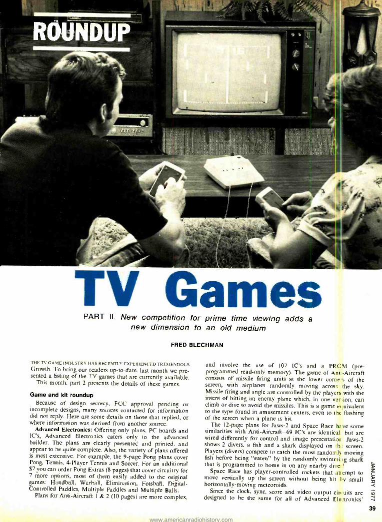
TV Games PART II. New competition for prime time viewing adds a
new dimension to an old medium
FRED BLECHMAN
THE TV GAME INDUSTRY HAS RECENTLY EXPERIENCED TREMENDOUS Growth. To bring our readers up -to -date. last month we pre- sented a fisting of the TV games that are currently available.
This month, part 2 presents the details of these games.
Game and kit roundup Because of design secrecy, FCC approval pending or
incomplete designs, many sources contacted for information did not reply. Here are some details on those that replied, or where information was derived from another source.
Advanced Electronics: Offering only plans, PC boards and IC's, Advanced Electronics caters only to the advanced builder. The plans are clearly presented and printed, and appear to be quite complete. Also, the variety of plans offered is most extensive. For example, the 9 -page Pong plans cover Pong, Tennis, 4- Player Tennis and Soccer. For an additional $7 you can order Pong Extras (8 pages) that cover circuitry for 7 more options, most of them easily added to the original games: Handball, Warball, Elimination, Fotsball, Digital - Controlled Paddles, Multiple Paddles and Multiple Balls.
Plans for Anti -Aircraft I & 2 (10 pages) are more complex,
and involve the use of 107 IC's and a PR programmed read -only memory). The game of A consists of missile firing units at the lower con
with airplanes randomly moving acros Missile firing and angle are controlled by the play intent of hitting an enemy plane which, in one v climb or dive to avoid the missiles. This is a game to the type found in amusement centers, even to t of the screen when a plane is hit.
The 12 -page plans for Jaws -2 and Space Race similarities with Anti -Aircraft -69 IC's are identisc wired differently for control and image presentati shows 2 divers, a fish and a shark displayed on Players (divers) compete to catch the most rando fish before being "eaten" by the randomly swi that is programmed to home in on any nearby di
Space Race has player -controlled rockets that move vertically up the screen without being hit horizontally- moving meteoroids.
Since the clock, sync, score and video output designed to be the same for all of Advanced
CM (pre- nt-Aircraft
r tes of the the sky.
ers with the er;ion, can e iuivalent ht flashing
h ve some al but are or. Jaws -2 h ! screen.
m1) moving mrii tg shark
ve: !
at empt to l 'y small
cin nits are Ele :cronies'
39
www.americanradiohistory.com
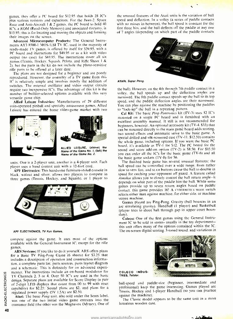
games, they offer a PC board for $12.95 that holds 28 IC's plus various resistors and capacitors. For the Jaws -2. Space Race and Anti -Aircraft 1 & 2 games. the PC board to hold 40 IC's. a ROM (Read -Only Memory) and associated circuitry. is
$15.95: this is for locating and moving the objects and forming their images on the screen.
Advanced Microcomputer Products: The General Instru- ments AY3 8500 -1 MOS /LSI TV IC, used in the majority of ready -made TV games. is offered by itself for $39.95. with a
PC board and instructions for $49.95 or as a kit with video output (no case) for $69.95. The instructions cover all six games (Tennis. Hockey. Squash. Pelota, and Rifle Shoot 1 &
2). but the parts in the kit do not include the photo- sensitive rifle parts to be offered at a later date.
The plans are not designed for a beginner and are poorly reproduced. However. the assembly of a TV game from this IC is relatively simple and involves mostly the addition of switches. The external oscillator and video output circuits require two inexpensive IC's. The advantage of this kit is the number of builder -selected options available with this very versatile game chip.
Allied Leisure Industries: Manufacturers of 29 different coin -operated pinball and specialty amusement games. Allied Leisure has entered the home video -game market with two
ALLIED LEISURE, (above) the Name of the Game No. 1, (left) the Name of the Game No. 2.
units. One is a 2- player unit. another is a 4- player unit. Each player uses a hand control unit with a 12 -foot cord.
APF Electronics: This handsome furniture -styled console in black, walnut and silver, allows two players to compete in
three games (Tennis. Hockey, and Squash), or 1 player to
APF ELECTRONICS, TV Fun Games.
compete against the game. It uses most of the options available with the General Instrument IC, except for the rifle games.
ARS Systems: If you like to do it yourself, ARS offers plans for a Basic TV Ping -Pong Game (6 sheets) for $3.25 that includes a description of operation and construction informa- tion. a complete parts list. parts sources, parts layout diagram and a schematic. This is definitely for an advanced experi- menter. The instructions include an on -board modulator for TV Channels 2, 3 or 4. Over 50 IC's are used in the basic design. Separate plans are available for Score Display (a pair of 2 -digit LED displays that count from 00 to 99 with reset capability) for $2.25: Sound plans are $2, and plans for a
regulated power supply (5V 1.5A) are $2.50. Atari: The basic Pong unit, also sold under the Sears label,
was one of the two initial video game entrants into the consumer field (the other was the Magnavox Odyssey). One of
the unusual features of the Atari units is the variation of ball speed and deflection. In a volley (a series of paddle contacts with no misses in- between), the ball speed is constant for the first three hits, and the ball deflects off the paddle at any one of 7 angles (depending on which part of the paddle contacts
ATARI, Super Pong.
the ball). However, on the 4th through 7th paddle contact in a
volley, the ball speeds up and the deflection angles are narrowed. The 8th paddle contact speeds up the ball to its top speed. and the paddle deflection angles are their narrowest. You can play against the machine by positioning the paddles to "lock -up" the ball in a repeating pattern.
Cal Kit: The basic Ping -Pontronics kit (TV -3) uses 12 IC's mounted on a single PC board and is furnished with an excellent assembly manual. It still is not recommended for beginners, however. An optional accessory kit (TV -4, $33) that can be mounted directly to the main game board adds scoring. two sound effects and automatic serve to the basic game. A
special drilled and silk -screened case (TV -11. $12.50) contains the whole game. including options. If you want the basic PC
hoard. it's available as TV -1 for $12. The PC board for the sound and score add -on option (TV -2) is $8.50. For $15.50 you can order all the IC's for the basic game (TV -6) and all
the basic game sockets (TV -8) for $6. The finished basic game has several unusual features: the
ball speed can be controlled over a wide range. from rather slow to very fast, and SLAM buttons cause the ball to double in
speed for catching your opponent off guard. A feature called Aimshot allows you to closely control the ball return angle -it depends on what part of the paddle hits the ball. While some games provide up to seven return angles based on paddle contact, this game provides 16! A CYBERNETICS MODE switch selects either man against machine, for either side, or machine versus machine.
Games played are Ping -Pong, Gravity (ball bounces in an arc simulating gravity). Handball (1 player) and Basketball (player tries to shoot ball through gap in upper court boun- dary).
Coleco: One of the first games using the General Instru- ment IC to be sold in stores -usually in the toy department - this unit offers many of the options contained within the IC.
The on- screen digital scoring, 3 -toned sound, and variations in
COLECO INDUS- TRIES, Telstar.
ball -speed and paddle -size professional) keep the game Tennis, Hockey and 1- player against the machine).
The Classic model appears to be the same unit in a more luxurious wooden case.
(beginner, intermediate and interesting. Games played are Handball (so you can practice
www.americanradiohistory.com
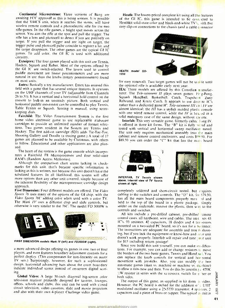
Continental Microsystems: Three versions of Bang are awaiting FCC approval as this is being written. It is possible that the V44CS unit, when it reaches the stores, will have wireless remote controls and a photoelectric rifle for toe two rifle- games. In the rifle games, a bright spot moves across the screen. You aim the rifle at the spot and pull the trigger. The rifle has a lens and photocell to detect if you are precisely on target. If you pull the trigger and are right on target, the trigger pulse and photocell pulse coincide to register a hit. and the target disappears. The other games are the typical GI IC games. To add color. the GI IC is used with additional circuitry.
Exterprex: The four games played with this unit are Tennis, Hockey, Squash and Robot. Most of the options offered by the GI IC are switch- selected. The levers used to control paddle movement are linear potentiometers and are more natural in use than the knobs (rotary potentiometers) found on most units.
Entex: Basically a toy manufacturer, Entex has entered this field with a game that has several unique features. It operates on the UHF channels of your TV (adjustable from Channels 26 to 31). It has a vertical and a horizontal hold control on the console to lock -in an unsteady picture. Both vertical and horizontal paddle movement can be controlled to play Tennis. Table Tennis or Squash. Scoring is manual. using score - keeping dials.
Fairchild: The Video Entertainment System is the first home video electronic game to use replaceable Videocart cartridges to provide an unlimited number of format selec- tions. Two games resident in the System are Tennis and Hockey. The first add -on cartridge ($20) adds Tic -Tac -Toe. Shooting Gallery and Doodle (a tracing game.) A total of 17 games are planned to be available by Christmas, with others to follow. Educational and other applications are also plan- ned.
The heart of the system is the game console which incorpo- rates a Fairchild F8 Microprocessor and four solid -state RAM's (Random Access Memories).
Although the comparison chart seems lacking in check - marks for this unit, that's because specific information is lacking as this is written. not because this unit doesn't have the tabulated features. In all likelihood. this system will offer more options than any other unit covered, simply because of the inherent flexibility of the microprocessor /cartridge design approach. First Dimension: Four different models are offered. The Video Sports 76 uses many of the options of the GI chip. with the Video Sports 76C adding color when used with a color TV. The Mark IV uses a different chip and slide controls, but otherwise is very similar to the 76C. The model FD 30O0W is
FIRST DIMENSION models Mark IV (left) and FD3000W (right). a.
\
a more advanced design offering six games in one. two or four players. and even features boundary adjustment controls for a perfect display. (This compensates for non -linearity on many TV sets.) Surprisingly. however. for such a sophisticated design. horizontal advancing bars above the court boundary indicate individual scores instead of on- screen digital scor- ing.
Global Video: A large 50 -inch diagonal big- screen color television receiver primarily designed for taverns, lounges. offices, schools and clubs, this unit can be used with dosed circuit television, video cassettes, slide and movie projectors and also with their own 4- player Challenge video game.
Heath: The lowest -priced complete kit using all the features of the GI IC, this game is intended to be connr:cted to Heathkit solid -state color and black- and -white TV's:. vith five easy clip -on connections to the chassis (and a cable o innector
HEATH model GD- 1350
for easy removal). Two target games will not be u: aide until the optional rifle is available early next year. IEA: Three models are offered by this Canadian a anufac- turer. The Tele- tainment II plays seven games: Piro Pong, Squash Handball, Basketball, Catch, Trapshcci Zany Rebound, and Krazy Catch. It appears to use discrte IC's rather than a dedicated game IC. Tele- tainment III < n 1 /V are almost identical; the III has a stylish molded plastic console with one wired remote control, while the IV is he u: ed in a solid mahogany case of the same design. without rerlote.
Interfab: This very versatile game, formerly collet Fong IV, is offered in three kit forms. The "B" kit is fully wi ed and tested with vertical and horizontal sweep oscillator_ tuned. The unit only requires mechanical assembly into tt e main cabinet and remote control enclosures, and costs $ "tc+ 50. For $89.50 you can order the "C" kit that has the m,ii: i board
c1111Qii INTERFAB, TV Tennis shown above. Internal view of TV Tennis shown at right.
completely soldered and short -circuit tested. but r:quires cabling to the switches and controls. The "D" kit. for ~79.50. has all the main board components properly mown :d and held to the top of the board in a plastic package. Simply solder on the underside, remove the plastic. then wire to the controls and switches.
All kits include a pre -drilled cabinet. pre -drilled -emote control cases, all hardware, wire and cables. The unit ises 43 IC's. 93 resistors. 42 capacitors, 18 diodes and 4 transistors mounted on a two -sided PC board, so it's not for a hennner. The instructions are adequate for assembly and trou 3I1ß'shoot- ing. but if you lack the equipment or know -how and ict.ir unit doesn't work properly, Interfab will repair and tune °. &air unit for $15 including return postage!
Since you build this unit yourself, you can make Inc difica- tions. For example. you can add or change resistors t move the borders of the two basic games. Tennis and Handba 1. You can replace the knob controls for vertical and lt+oir zontal movement with joysticks. Also. you can modify tt e two automatic games (man vs. machine or machine vs. 11"K chine) to allow a miss now and then. You do this by insertin; 470K 1/2W resistor in series with the AUTOMATIC switch for et her or both sides.
The output of this game, as supplied in kit form is video. However, the PC board is etched for the addition or' UHF modulated oscillator using a 2N5770 transistor. 4 re:i =tors, 2 capacitors and a piece of brass or copper. The typical o cuit is
www.americanradiohistory.com
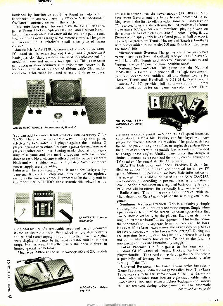
furnished by Interfab or could be found in radio circuit handbooks -or you could use the PXV -2A VHF Modulated Oscillator mentioned earlier in this article.
Interstate Industries: This unit plays the GI IC standard games Tennis. Hockey. 2- player Handball and 1- player Hand- ball in black- and -white, but offers all the available paddle and ball options as well as using wired remote controls. The game is packaged in a relatively small smartly- styled main console.
James: Kit A, for $179.95, consists of a professional game PC board that is assembled and tested, and 2 professional Kraft joysticks (these joysticks are used in radio- control for model airplanes and are very high quality). This is the same game seen in many commercial establishments. Accessory B.
for $3.95, consists of six feet of ribbon cable (flat multi - conductor color -coded insulated wires) and three switches.
it Illlrlril..,
.1111! 111 Pif., 3111111W {11111 11117
JAMES ELECTRONICS, Accessories A, B and C.
You can add two more Kraft joysticks with Accessory C for $39.95. There are actually four ways to play this game, selected by two switches: 1 player against the machine, 2
players against each other. 3 players against the machine or 4
players against each other. Scoring marks show at the begin- ning of a game and one mark disappears with each score down to zero. No enclosure is offered and the output is strictly black- and -white video. Also, a regulated 5 -volt 2- ampere power supply must be added. Lafayette: The Tournament 2000 is made for Lafayette by
Unisonic. It uses a GI chip and offers most of the options, including the two rifle games. It appears to be the only unit in
this report that INCLUDES the electronic rifle, which has the
LAFAYETTE, Tourna- ment 2000.
additional feature of a removable stock and barrel to convert it into an electronic pistol. With wired remote slide controls and manual scorekeeping in addition to the on- screen digital score display, this may be the most versatile unit in its price range. Furthermore. Lafayette lowers the price at times in
limited special promotions. Magnavox: Although the older Odyssey 100 and 200 models
MAGNAVOX, Odys- sey 500.
are still in some stores, the newer models (300, 400 and 500)
have more features and are being heavily promoted. Also,
Magnavox is the first to offer a video game built -into a color TV receiver. They are also offering the first ready -made home video game (Odyssey 500) with simulated playing figures on
the screen instead of rectangles, and full -color playing fields.
(Some color displays only have colored paddles, ball or score). The regular games are Tennis, Hockey and Smash (Handball) with Soccer added to the model 500 and Smash omitted from the model 100.
Microelectronic Systems: The games are Ricochet (player versus machine in 3 -wall Handball), Racquetball (2- player 3-
wall Handball), Tennis and Hockey. Various switches and buttons provide 72 possible game combinations!
National Semiconductor: This game uses the National MM57I00 TV Game IC to provide all the logic necessary to generate backgrounds, paddles, ball and digital scoring for Hockey, Tennis and Handball. A 3.58 MHz crystal and a
divide- by -31/2 IC provide full color -including different colored backgrounds for each game -on color TV sets. There
NATIONAL SEMI- CONDUCTOR, Adver- sary.
are three selectable paddle sizes and the ball speed increases automatically after 4 hits. Hockey can be played with one
player for practice against the machine. The paddles deflect the ball or puck at any one of seven angles depending upon the point of contact with the paddle, but no switch is provided to change these angles. Unlike many units. this design is
limited to manual serve only and the sound comes through the TV speaker. The unit is strictly AC powered.
RCA: The Distributor and Special Products Division has
filed an application for FCC type approval for a new TV
game. Although, at presstime, we have little information on
this new game, it is said to be based on the RCA COS MAC
microprocessor. According to present plans. it is tentatively scheduled for introduction on a regional basis during January 1977, and will be offered for nationally later in the year.
Radio Shack: This unit appears to be identical with the Microelectronics Ricochet, except for the names given to the games.
Southwest Technical Products: This is a relatively simple kit using only 10 IC's, but only has video output. Single white
squares on each side of the screen represent space ships that can be moved vertically by the players. Each can also fire a
single -burst "laser beam" at the opponent. If hit by the beam, the opponent's ship disappears from the screen and he loses.
However, if the laser beam misses, the aggressor's ship blinks for several seconds while his laser is "recharging ". During this
recharge time (since he can't fire) his only defense is to keep out of his adversary's line of fire. To add to the fun, the movement controls are intentionally sluggish!
Tokyo Phoenix: The four games in this unit are the standard GI IC games of Tennis, Hockey, Squash and 1-
player Handball. The sound comes through the TV, so there is
a possibility of leaving the game on unintentionally after turning off the TV.
Universal Research: The Video Action series includes a
Game Table and an educational game called Fact. The Game Table appears to be the Video Action IV with a black -and- white video monitor built into an eight -sided table with a
card -playing top and checkers /chess /backgammon inserts
that are removed during video game play. The automatic continued on page 84
www.americanradiohistory.com
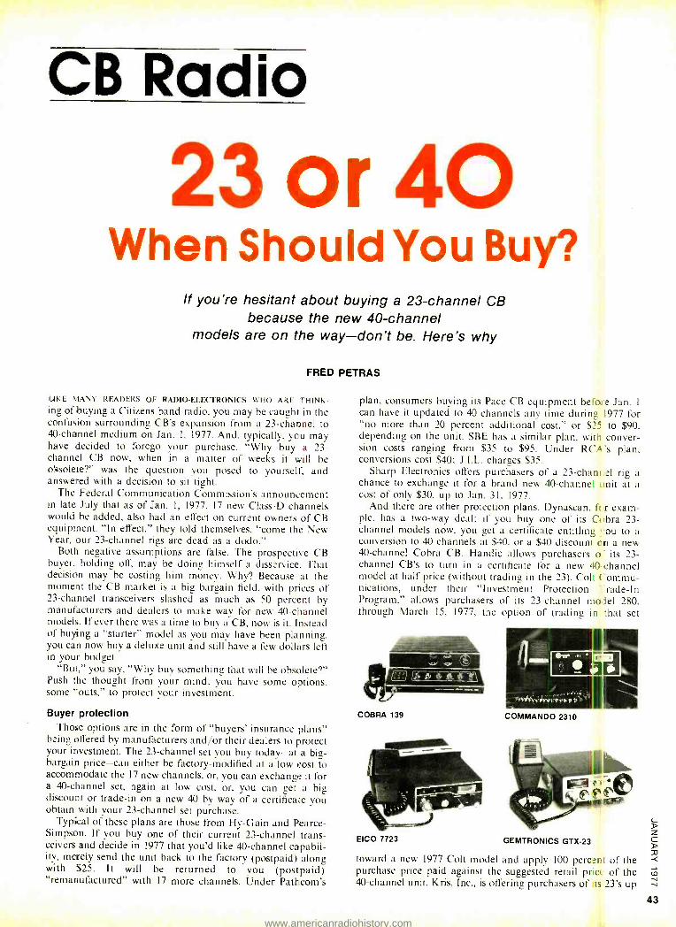
CB Radio
23 or 40 When Should You Buy?
If you're hesitant about buying a 23- channel CB because the new 40- channel
models are on the way -don't be. Here's why
FRED PETRAS
LIKE MANY READERS OE RADIO -ELECTRONICS WHO ARE THINK -
ing of buying a Citizens band radio, you may be caught in the confusion surrounding CB's expansion from a 23- channel to 40- channel medium on Jan. I. 1977. And, typically, ycu may have decided to forego your purchase. "Why buy a 23- channel CB now, when in a matter of weeks it will be obsolete?" was the question you posed to yourself, and answered with a decision to sit tight.
The Federal Communication Commission's announcement in late July that as of Jan. I, 1977. 17 new Class -D channels would be added, also had an effect on current owners of CB equipment. "In effect." they told themselves, "come the New Year. our 23- channel rigs are dead as a dodo."
Both negative assumptions are false. The prospective CB buyer, holding off, may be doing himself a disservice. That decision may be costing him money. Why? Because at the moment the CB market is a big bargain field, with prices of 23- channel transceivers slashed as much as 50 percent by manufacturers and dealers to make way for new 40- channel models. If ever there was a time to buy a CB, now is it. Instead of buying a "starter" model as you may have been planning, you can now buy a deluxe unit and still have a few dollars left in your budget.
"But," you say, "Why buy something that will be obsolete ?" Push the thought from your mind; you have some options. some "outs," to protect your investment.
Buyer protection Those options are in the form of "buyers' insurance plans"
being offered by manufacturers and /or their dealers to protect your investment. The 23- channel set you buy today -at a big - bargain price -can either be factory- modified at a low cost to accommodate the 17 new channels, or, you can exchange it for a 40- channel set, again at low cost, or, you can get a big discount or trade -in on a new 40 by way of a certificate you obtain with your 23- channel set purchase.
Typical of these plans are those from Hy -Gain and Pearce - Simpson. If you buy one of their current 23- channel trans- ceivers and decide in 1977 that you'd like 40- channel capabil- ity, merely send the unit back to the factory (postpaid) along with $25. It will be returned to you (postpaid) "remanufactured" with 17 more channels. Under Pathcom's
plan, consumers buying its Pace CB equipment be'o: e Jan. I
can have it updated to 40 channels any time during 1977 for "no more than 20 percent additional cost," or $25 to $90, depending on the unit. SBE has a similar plan. with conver- sion costs ranging from $35 to $95. Under RCA 's plan. conversions cost $40; J.I.L. charges $35.
Sharp Electronics offers purchasers of a 23 -chant el rig a chance to exchange it for a brand new 40- channel unit at a cost of only $30, up to Jan. 31, 1977.
And there are other protection plans. Dynascan, fc r exam- ple, has a two -way deal: if you buy one of its Cobra 23- channel models now, you get a certificate entitling ' ou to a conversion to 40 channels at $40, or a $40 discount on a new 40- channel Cobra CB. Handic allows purchasers o its 23- channel CB's to turn in a certificate for a new 40- channel model at half price (without trading in the 23). Colt Commu- nications, under their "Investment Protection :rade -In Program," allows purchasers of its 23- channel model 280, through March 15, 1977, the option of trading in that set
COBRA 139
EICO 7723
COMMANDO 2310
GEMTRONICS GTX-23
toward a new 1977 Colt model and apply 100 perc.°nt of the purchase price paid against the suggested retail price of the 40- channel unit. Kris. Inc., is offering purchasers of is 23's up
www.americanradiohistory.com
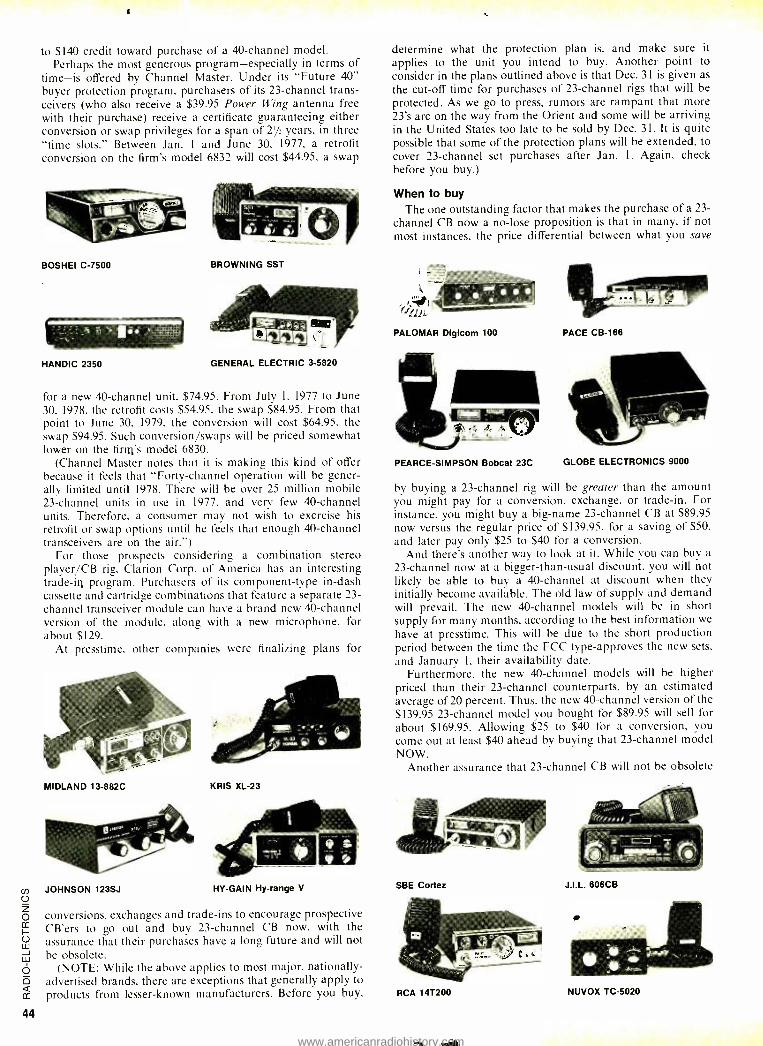
44
to $140 credit toward purchase of a 40- channel model. Perhaps the most generous program- especially in terms of
time -is offered by Channel Master. Under its "Future 40" buyer protection program, purchasers of its 23- channel trans- ceivers (who also receive a $39.95 Power Wing antenna free with their purchase) receive a certificate guaranteeing either conversion or swap privileges for a span of 21/2 years, in three "time slots." Between Jan. I and June 30, 1977, a retrofit conversion on the firm's model 6832 will cost $44.95, a swap
BOSHEI C-7500 BROWNING SST
HANDIC 2350 GENERAL ELECTRIC 3 -5820
for a new 40- channel unit. $74.95. From July 1, 1977 to June 30, 1978. the retrofit costs $54.95, the swap $84.95. From that point to June 30, 1979. the conversion will cost $64.95, the swap $94.95. Such conversion /swaps will be priced somewhat lower on the firm's model 6830.
(Channel Master notes that it is making this kind of offer because it feels that "Forty- channel operation will be gener- ally limited until 1978. There will be over 25 million mobile 23- channel units in use in 1977, and very few 40- channel units. Therefore, a consumer may not wish to exercise his retrofit or swap options until he feels that enough 40- channel transceivers are on the air. ")
For those prospects considering a combination stereo player /CB rig. Clarion Corp. of America has an interesting trade -in program. Purchasers of its component -type in -dash cassette and cartridge combinations that feature a separate 23- channel transceiver module can have a brand new 40- channel version of the module, along with a new microphone, for about $129.
At presstime, other companies were finalizing plans for
MIDLAND 13 -882C KRIS XL -23
JOHNSON 123SJ HY-GAIN Hy-range V
conversions, exchanges and trade -ins to encourage prospective CB'ers to go out and buy 23- channel CB now, with the assurance that their purchases have a long future and will not be obsolete.
(NOTE: While the above applies to most major, nationally - advertised brands, there are exceptions that generally apply to products from lesser -known manufacturers. Before you buy,
determine what the protection plan is, and make sure it applies to the unit you intend to buy. Another point to consider in the plans outlined above is that Dec. 31 is given as the cut -off time for purchases of 23- channel rigs that will be protected. As we go to press, rumors are rampant that more 23's are on the way from the Orient and some will be arriving in the United States too late to be sold by Dec. 31. It is quite possible that some of the protection plans will be extended, to cover 23- channel set purchases after Jan. 1. Again, check before you buy.)
When to buy The one outstanding factor that makes the purchase of a 23-
channel CB now a no -lose proposition is that in many, if not most instances, the price differential between what you save
PALOMAR Digicom 100
PEARCE -SIMPSON Bobcat 23C
PACE CB -166
GLOBE ELECTRONICS 9000
by buying a 23- channel rig will be greater than the amount you might pay for a conversion, exchange, or trade -in. For instance, you might buy a big -name 23- channel CB at $89.95 now versus the regular price of $139.95. for a saving of $50, and later pay only $25 to $40 for a conversion.
And there's another way to look at it. While you can buy a
23- channel now at a bigger- than -usual discount, you will not likely be able to buy a 40- channel at discount when they initially become available. The old law of supply and demand will prevail. The new 40- channel models will be in short supply for many months, according to the best information we
have at presstime. This will be due to the short production period between the time the FCC type- approves the new sets, and January I, their availability date.
Furthermore, the new 40- channel models will be higher priced than their 23- channel counterparts, by an estimated average of 20 percent. Thus, the new 40- channel version of the $139.95 23- channel model you bought for $89.95 will sell for about $169.95. Allowing $25 to $40 for a conversion, you come out at least $40 ahead by buying that 23- channel model NOW.
Another assurance that 23- channel CB will not be obsolete
SBE Cortez
RCA 14T200
J.I.L. 606CB
NUVOX TC-5020
www.americanradiohistory.com
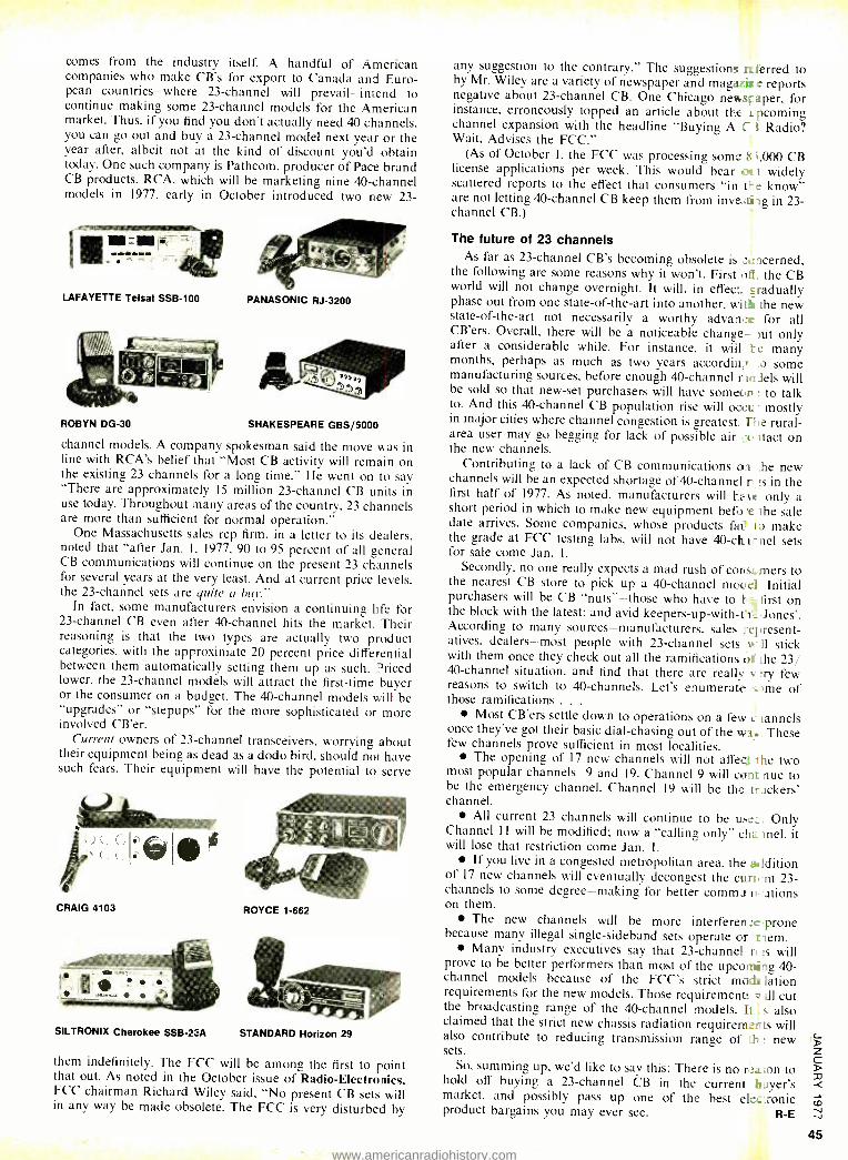
comes from the industry itself. A handful of American companies who make CB's for export to Canada and Euro- pean countries -where 23- channel will prevail -intend to continue making some 23- channel models for the American market. Thus, if you find you don't actually need 40 channels, you can go out and buy a 23- channel model next year or the year after, albeit not at the kind of discount you'd obtain today. One such company is Pathcom, producer of Pace brand CB products. RCA, which will be marketing nine 40- channel models in 1977, early in October introduced two new 23-
LAFAYETTE Telsat SSB-100 PANASONIC RJ -3200
ROBYN DG -30 SHAKESPEARE GBS /5000
channel models. A company spokesman said the move was in line with RCA's belief that "Most CB activity will remain on the existing 23 channels for a long time." He went on to say "There are approximately 15 million 23- channel CB units in use today. Throughout many areas of the country. 23 channels are more than sufficient for normal operation."
One Massachusetts sales rep firm, in a letter to its dealers, noted that "after Jan. 1, 1977, 90 to 95 percent of all general CB communications will continue on the present 23 channels for several years at the very least. And at current price levels. the 23- channel sets are quite a but."
In fact, some manufacturers envision a continuing life for 23- channel CB even after 40- channel hits the market. Their reasoning is that the two types are actually two product categories, with the approximate 20 percent price differential between them automatically setting them up as such. priced lower, the 23- channel models will attract the first -time buyer or the consumer on a budget. The 40- channel models will be "upgrades" or "stepups" for the more sophisticated or more involved CB'er.
Current owners of 23- channel transceivers, worrying about their equipment being as dead as a dodo bird, should not have such fears. Their equipment will have the potential to serve
ift; i- C,, a ;
CRAIG 4103 ROYCE 1 -662
SILTRONIX Cherokee SSB -23A STANDARD Horizon 29
them indefinitely. The FCC will be among the first to point that out. As noted in the October issue of Radio -Electronics, FCC chairman Richard Wiley said, "No present CB sets will in any way be made obsolete. The FCC is very disturbed by
any suggestion to the contrary." The suggestions referred to by Mr. Wiley are a variety of newspaper and mag:3.::ir e reports negative about 23- channel CB. One Chicago newstaper, for instance, erroneously topped an article about the i. pcoming channel expansion with the headline "Buying A C I Radio? Wait, Advises the FCC."
(As of October 1, the FCC was processing some 8 ,000 CB license applications per week. This would bear ix t widely scattered reports to the effect that consumers "in 0-.e know" are not letting 40- channel CB keep them from inve ;tizg in 23- channel CB.)
The future of 23 channels As far as 23- channel CB's becoming obsolete is xacerned,
the following are some reasons why it won't. First o$. the CB world will not change overnight. It will, in effect. _radually phase out from one state -of- the -art into another, with the new state -of -the -art not necessarily a worthy advan,.r for all CB'ers. Overall, there will be a noticeable change- )ut only after a considerable while. For instance, it will 1e many months, perhaps as much as two years accordiri; :o some manufacturing sources, before enough 40- channel mcJels will be sold so that new -set purchasers will have someon to talk to. And this 40- channel CB population rise will occu- mostly in major cities where channel congestion is greatest. Ile rural - area user may go begging for lack of possible air co ,tact on the new channels.
Contributing to a lack of CB communications of he new channels will be an expected shortage of 40- channel rr, :s in the first half of 1977. As noted. manufacturers will have only a short period in which to make new equipment before the sale date arrives. Some companies, whose products f a i I D make the grade at FCC testing labs, will not have 40- clurnel sets for sale come Jan. 1.
Secondly, no one really expects a mad rush of consL mers to the nearest CB store to pick up a 40- channel moccl Initial purchasers will be CB "nuts" -those who have to be first on the block with the latest; and avid keepers -up- with -nir.- Jones'. According to many sources -manufacturers, sales represent- atives, dealers -most people with 23- channel sets u-11 stick with them once they check out all the ramifications oÍ the 23/ 40- channel situation, and find that there are really v :ry few reasons to switch to 40- channels. Let's enumerate i. me of those ramifications . . .
Most CB'ers settle down to operations on a few c iannels once they've got their basic dial -chasing out of the wad.. These few channels prove sufficient in most localities.
The opening of 17 new channels will not affect the two most popular channels -9 and 19. Channel 9 will cons nue to be the emergency channel. Channel 19 will be the trackers' channel.
All current 23 channels will continue to be useL:. Only Channel 1 I will be modified; now a "calling only" cha.mel, it will lose that restriction come Jan. 1.
If you live in a congested metropolitan area, the addition of 17 new channels will eventually decongest the cure, nt 23- channels to some degree- making for better comma. ations on them.
The new channels will be more interferen_e prone because many illegal single -sideband sets operate or teem.
Many industry executives say that 23-channel n 's will prove to be better performers than most of the upcomii-ig 40- channel models because of the FCC's strict mode lation requirements for the new models. Those requirement: ill cut the broadcasting range of the 40- channel models. It s also claimed that the strict new chassis radiation requirem_nts will also contribute to reducing transmission range of It : new sets.
So, summing up, we'd like to say this: There is no rr.aion to hold off buying a 23- channel CB in the current hayer's market, and possibly pass up one of the best elec:ronic product bargains you may ever see. R -E
45
www.americanradiohistory.com
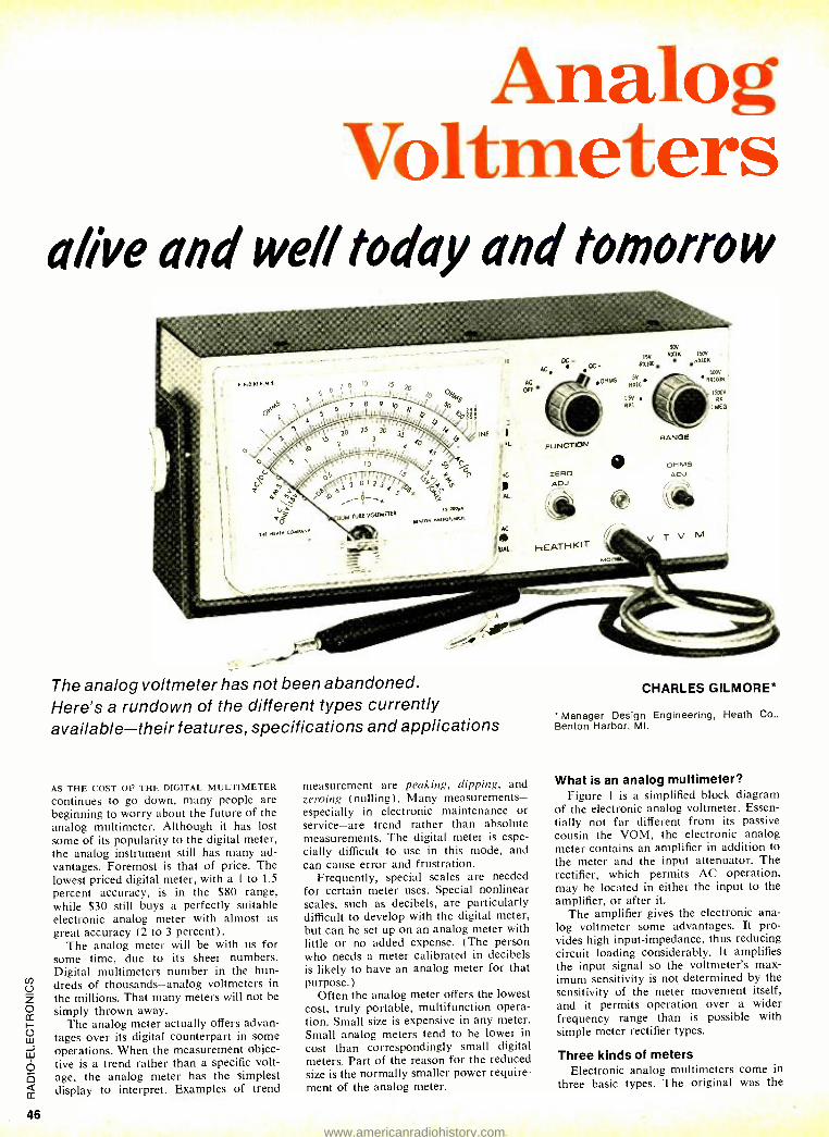
46
Analog Voltmeters
al/ve and well today and tomorrow
50v
ISV R.IK
DD R%100.
,LOISMS P%10
150V
P%ION
50pV
R%100K
1500V
RX
1 MEG
RI
00M TUBE VOLTMETER
ZERO ADJ.
(iLl
RANGE
DH MS ADJ
The analog voltmeter has not been abandoned. Here's a rundown of the different types currently available -their features, specifications and applications
AS THE COST OF THE DIGITAL MULTIMETER
continues to go down, many people are beginning to worry about the future of the analog multimeter. Although it has lost some of its popularity to the digital meter, the analog instrument still has many ad- vantages. Foremost is that of price. The lowest priced digital meter, with a 1 to 1.5
percent accuracy, is in the $80 range, while $30 still buys a perfectly suitable electronic analog meter with almost as great accuracy (2 to 3 percent).
The analog meter will be with us for some time, due to its sheer numbers. Digital multimeters number in the hun- dreds of thousands -analog voltmeters in the millions. That many meters will not be simply thrown away.
The analog meter actually offers advan- tages over its digital counterpart in some operations. When the measurement objec- tive is a trend rather than a specific volt- age, the analog meter has the simplest display to interpret. Examples of trend
measurement are peaking, dipping, and zeroing (nulling). Many measurements - especially in electronic maintenance or service -are trend rather than absolute measurements. The digital meter is espe- cially difficult to use in this mode, and can cause error and frustration.
Frequently, special scales are needed for certain meter uses. Special nonlinear scales, such as decibels, are particularly difficult to develop with the digital meter, but can be set up on an analog meter with little or no added expense. (The person who needs a meter calibrated in decibels is likely to have an analog meter for that purpose.)
Often the analog meter offers the lowest cost, truly portable, multifunction opera- tion. Small size is expensive in any meter. Small analog meters tend to be lower in cost than correspondingly small digital meters. Part of the reason for the reduced size is the normally smaller power require- ment of the analog meter.
CHARLES GILMORE*
* Manager Design Engineering, Heath Co.. Benton Harbor, MI.
What is an analog multimeter? Figure 1 is a simplified block diagram
of the electronic analog voltmeter. Essen- tially not far different from its passive cousin the VOM, the electronic analog meter contains an amplifier in addition to the meter and the input attenuator. The rectifier, which permits AC operation, may be located in either the input to the amplifier, or after it.
The amplifier gives the electronic ana- log voltmeter some advantages. It pro- vides high input- impedance, thus reducing circuit loading considerably. It amplifies the input signal so the voltmeter's max- imum sensitivity is not determined by the sensitivity of the meter movement itself, and it permits operation over a wider frequency range than is possible with simple meter rectifier types.
Three kinds of meters Electronic analog multimeters come in
three basic types. The original was the
www.americanradiohistory.com
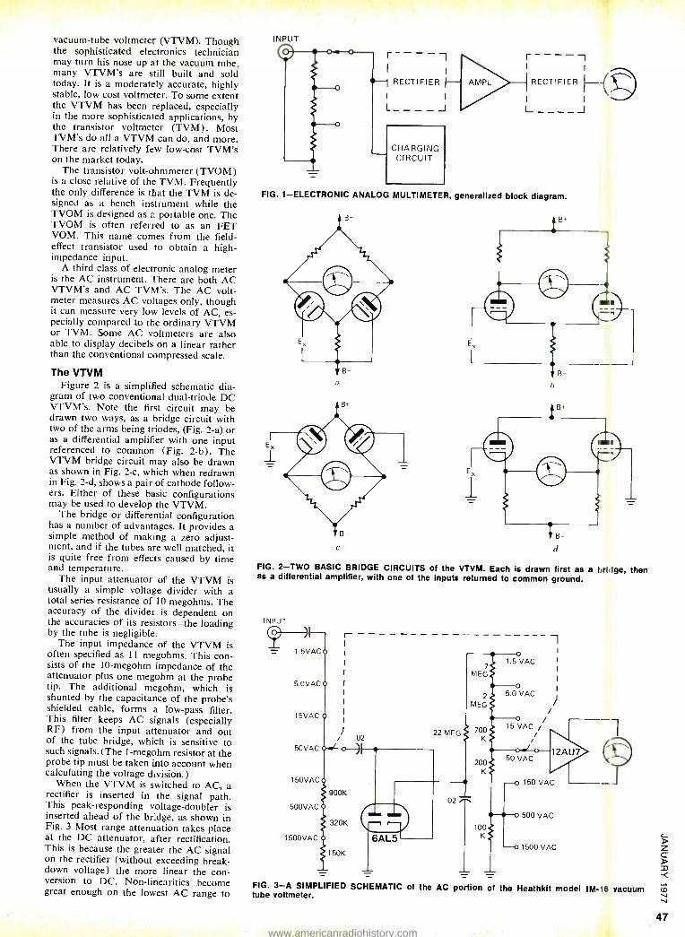
vacuum -tube voltmeter (VTVM). Though the sophisticated electronics technician may turn his nose up at the vacuum tube, many VTVM's are still built and sold today. It is a moderately accurate, highly stable, low cost voltmeter. To some extent the VTVM has been replaced, especially in the more sophisticated applications, by the transistor voltmeter (TVM). Most TVM's do all a VTVM can do, and more. There are relatively few low -cost TVM's on the market today.
The transistor volt -ohmmeter (TVOM) is a close relative of the TVM. Frequently the only difference is that the TVM is de- FIG. 1- ELECTRONIC ANALOG MULTIMETER, generalized block diagram. signed as a bench instrument while the TVOM is designed as a portable one. The TVOM is often referred to as an FET VOM. This name comes from the field - effect transistor used to obtain a high - impedance input.
A third class of electronic analog meter is the AC instrument. There are both AC VTVM's and AC TVM's. The AC volt- meter measures AC voltages only, though it can measure very low levels of AC, es- pecially compared to the ordinary VTVM or TVM. Some AC voltmeters are also able to display decibels on a linear rather than the conventional compressed scale.
The VTVM Figure 2 is a simplified schematic dia-
gram of two conventional dual- triode DC VTVM's. Note the first circuit may be drawn two ways, as a bridge circuit with two of the arms being triodes, (Fig. 2 -a) or as a differential amplifier with one input referenced to common (Fig. 2 -b). The VTVM bridge circuit may also be drawn as shown in Fig. 2 -c, which when redrawn in Fig. 2 -d, shows a pair of cathode follow- ers. Either of these basic configurations may be used to develop the VTVM.
The bridge or differential configuration has a number of advantages. It provides a simple method of making a zero adjust- ment, and if the tubes are well matched, it is quite free from effects caused by time and temperature.
The input attenuator of the VTVM is usually a simple voltage divider with a total series resistance of 10 megohms. The accuracy of the divider is dependent on the accuracies of its resistors -the loading by the tube is negligible.
The input impedance of the VTVM is often specified as 11 megohms. This con- sists of the 10- megohm impedance of the attenuator plus one megohm at the probe tip. The additional megohm, which is shunted by the capacitance of the probe's shielded cable, forms a low -pass filter. This filter keeps AC signals (especially RF) from the input attenuator and out of the tube bridge, which is sensitive to such signals. (The 1- megohm resistor at the probe tip must be taken into account when calculating the voltage division.)
When the VTVM is switched to AC, a rectifier is inserted in the signal path. This peak- responding voltage- doubler is inserted ahead of the bridge, as shown in Fig. 3 Most range attenuation takes place at the DC attenuator, after rectification. This is because the greater the AC signal on the rectifier (without exceeding break- down voltage) the more linear the con- version to DC. Non -linearities become great enough on the lowest AC range to
INPUT
r----1 r - - - - -I I I 1 I
RECTIFIER AMPL RECTIFIER HD I I
I I
L__-_J L-__-J
C
v
t!
FIG. 2 -TWO BASIC BRIDGE CIRCUITS of the VTVM. Each is drawn first as a Itri ige, then as a differential amplifier, with one of the inputs returned to common ground.
INPUT
1.5VAC
5.0VAC
15VAC
5CVAC
150VAC
500VAC
1500VAC
t-
rJ .02
900K
320K
150K
7
MEG
2
MEG
700 K
200 K
FIG. 3 -A SIMPLIFIED SCHEMATIC of the AC portion of the Heathkit model IM- I vacuum tube voltmeter.
47
www.americanradiohistory.com
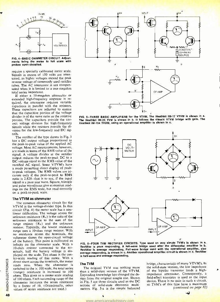
48
N
OHMS 56 10
o
J4_
DC VOLTMETER
FIG. 4 -BASIC OHMMETER CIRCUIT. Adjust- ments bring the meter to full scale with probes open- circuited.
require a specially calibrated meter scale. Signals in excess of 150 volts are atten- uated, as higher voltages exceed the peak reverse voltage of commonly used rectifier tubes. The AC attenuator is not compen- sated when it is limited to a one -megohm total series impedance.
If either a 10- megohm attenuator or extended high- frequency response is re- quired, the attenuator requires variable capacitors in parallel with the resistors. These capacitors are adjusted to ensure that the capacitive portion of the voltage divider is of the same ratio as the resistive portion. The capacitors provide the cor- rect voltage division for high- frequency signals while the resistors provide the di- vision for the low- frequency and DC sig- nals.
The rectifier of the type shown in Fig. 3
has a DC output voltage proportional to the peak -to -peak value of the applied AC voltage. Most AC measurements, however, are made in terms of the RMS value of the signal. A voltage divider at the rectifier output reduces the peak -to -peak DC to a DC voltage equal to the RMS value of the rectified AC signal. Some VTVM's have a mode permitting direct display of peak - to -peak voltages. The RMS valves are ac- curate only if the peak -to -peak to RMS ratio is 2.828 -that is to say, if the input signal is a pure sine wave. Square, triangle and pulse waveforms give erroneous read- ings on the RMS scale, but read correctly on a peak -to -peak scale.
The VTVM as ohmmeter The common ohmmeter circuit for the
VTVM is the voltage- divider type. In this circuit (Fig. 4) the meter scale has a non- linear calibration. The voltage across the unknown resistance (R.) is the ratio of the unknown resistance to the sum of the range resistor (RR) and the unknown resistor. Typically, the lowest resistance range uses a 10 -ohm range resistor. With no resistance across the terminals, the voltmeter shows the open- circuit voltage of the battery. This point is calibrated as infinity on the ohmmeter scale. With a 10 -ohm resistor connected to the ter- minals, half the battery voltage is dis- played on the scale. Ten ohms is the cen- ter -scale reading of this meter. With a direct short across the terminals, the meter reads zero. When the ohmmeter is switched to the X 100 scale, the total series (range) resistance is increased to 100 ohms. This gives us a center -scale reading of 100 ohms. Each succeeding range of the ohmmeter increases the series resistance by a factor of 10. (Occasionally, other values of series resistance are used.)
b
FIG. 5 -THREE BASIC AMPLIFIERS for the VTVM. The Heathkit IM -17 VTVM is shown in a.
The Heathkit IM -25 TVM is shown in b. It follows the classic VTVM bridge with gain. The
Heathkit IM -104 TVOM, using an operational amplifier is shown in c.
n
C d
FIG. 6 -FOUR TVM RECTIFIER CIRCUITS. Type used on very simple TVM's is shown in a.
Rectifier is peak responding. A full -wave bridge used after the differential amplifier in b.
Rectifier is average responding. Full -wave bridge used with the operational amplifier, also
average responding, is shown in c. Another operational amplifier circuit is shown in d. Rectifier
is half -wave and average responding.
The TVM The original TVM was nothing more
than a solid -state version of the VTVM. Expanding knowledge has changed the de- sign from the original simple one. Shown in Fig. 5 are three circuits used as the DC section of solid -state electronic multi - meters. Fig. 5 -a is the simple balanced
bridge, characteristic of many VTVM's. In the solid -state version, the low impedance of the bipolar transistor loads a high - impedance attenuator. Consequently, a field -effect transistor is used as the input device. There is no gain in such a circuit, so TVM's of this type have a maximum
(continued on page 82)
www.americanradiohistory.com
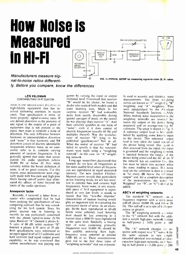
How Noise is Measured in HI -FI Manufacturers measure sig- nal -to -noise ratios different- ly. Before you compare, know the differences
REFERENCE SIGNAL GENERATOR
o
PRODUCT UNDER
TEST
LEN FELDMAN CONTRIBUTING HI -FI EDITOR
THERE IS ONE SPECIFICATION RELATING TO
high -fidelity equipment that has re- ceived increasing attention in recent years. That specification is noise, or more properly, signal -to -noise ratio. If one defines distortion as the presence of any signal in the output of a piece of equipment that is not present at the input, then noise is certainly a form of distortion. The only difference between harmonic or intermodulation distortion and "noise" is that harmonic and IM distortion consist of discrete identifiable frequencies whereas noise, as we com- monly refer to it, contains varying amounts of random frequencies. It is generally agreed that noise that occurs outside the audio spectrum (above 20,000 Hz or below 20 Hz), while certainly within the broad definition of noise, is of no great concern. For this reason, noise measurements were origi- nally made with low -pass and high -pass filters having cut -off points that elimi- nated the affects of noise beyond the limits of the audio spectrum.
Annoyance factor Recently, I received a letter from a
reader who complained that he had been studying the specifications of two competing receivers that he was consid- ering for his hi -fi system. Since his prime interest was in listening to records, he was particularly concerned with the phono signal -to -noise (S /N) ratio. Receiver "A" claimed a phono S/ N ratio of 60 dB, while receiver "B" boasted a phono S/N ratio of 70 dB. Both specifications were referenced to an input signal level of 2.5 millivolts and both receivers had equal output power capability, so he was convinced that neither manufacturer was playing any
i 0
LOAD
fî TVM PAD FOR LEVEL EDUALIZATION
WEIGHTING NETWORK
o
FIG. 1- TYPICAL SETUP for measuring signal -to -noise (S NI ratios.
games by varying the input or output reference level. Convinced that receiver "B" would be his choice, he found a dealer who stocked both models and did some listening tests. Much to his surprise, receiver "B" had noticeably more hum (easily discernible during quieter passages of music on the record he was playing) than receiver "A ". And hum certainly qualifies as one form of "noise ". even if it does consist of discrete frequencies (usually 60 Hz and multiples thereof). Was the manufac- turer of receiver "B" lying in his published specifications? Not at all. What the maker of receiver "B" had failed to specify is that his measure- ments were made using a "weighting network " -in this case, an "A" weight- ing network.
Long ago, researchers discovered that humans do not hear all frequencies at the same audible level when all frequen- cies are reproduced at equal measured intensity. The now familiar Fletcher - Munson curves reveals that particularly at low listening levels, we are less sensi- tive to extreme bass and extreme high frequencies. Since noise, in any reason- able piece of hi -fi equipment is repro- duced at very low levels, it stands to reason that this "non -flat response" characteristic of human hearing would play an important role in evaluating the annoyance factor of noise. As an exam- ple, 60 -Hz hum reproduced at 60 -dB below some arbitrary loud listening level should be less annoying to a listener than a 1000 -Hz tone reproduced at the same level. Similarly, a hissing type of noise containing primarily frequencies over 10,000 Hz should be less audibly annoying than high - frequency noise centered at around 5,000 Hz or so. These considerations gave rise to the first three types of "weighting networks" that are common-
ly used in acoustic and electrica noise measurements. The three w e ghting curves are known as "C" weigh it g, "B" weighting and "A" weighting. They were standardized by the A n erican National Standards Institute (ANSI). When making noise measuremerts, the weighting networks are insetted be- tween the output of the devil e being measured and an average -readü g AC voltmeter. The setup is shown i Fig. I. A reference output level is fir: t estab- lished by applying some knov n input to the device. This reference ?utput level is very often the rated oat nut of the device being tested. The nal is then removed from the input, the input is grounded and the weighting ni twork is inserted between the outpu the device being tested and the AC in ter. If the network has an insertion Its., this loss must be taken into account when the noise reading is taken. Tl e noise read on the voltmeter is then e: p-essed as "so many dB below the ref rence output" and. for a complete descJiption of the measurement, the wcres "A Weighted" (or "B ", or "C ") shp.i Id be added.
ABC's of weighting networks The standard "C" network tas a
frequency response with a corti luous roll -off above 10,000 Hz and b:1, ow 20 Hz. This roll -off is at a rate of 6 d I I -per- octave or greater.
The "B" weighting network is s milar to the "C" network but with tfe addi- tion a simple high -pass network laving its half -power ( -3dB) point a 160 Hz.
The "A" network changes :h: re- sponse with respect to a "C" netwc rk by the same amount as two s mple cascaded identical non -isolated tes istor- capacitor high -pass networks, ea :1 hav- ing its half power (-3 dB) poin t 280
www.americanradiohistory.com
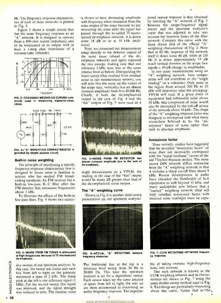
50
Hz. The frequency response characteris- tics of each of these networks is plotted in Fig. 2.
Figure 3 shows a simple circuit that has the same frequency response as an "A" network. It is designed to operate from a 600 -ohm source impedance and to be terminated at its output with at least a 1 -meg ohm impedance of a vacuum -tube voltmeter.
o
-10
20
-30 F 20Hz 100 1kHz
FREQUENCY
10 20kHz
FIG. 2- STANDARD WEIGHTING CURVES com- monly used in measuring signal -to -noise ratios.
0.33µF 0.33pF 10K 0.047NF /I o
60052
INPUT
1.8K
60012
o o
1.8K
.0022 OUTPUT
100K
FIG. 3 -"A" WEIGHTING CHARACTERISTIC is provided by simple passive circuit.
Built -in noise weighting The principle of interposing a specific
frequency- response characteristic that is
designed to lessen noise is familiar to anyone who has studied FM broad- casting standards. An FM receiver has a built -in low -pass R -C filter after the FM detector that attenuates frequencies above 1 kHz.
To illustrate the affects of the built -in low -pass filter, Fig. 4 shows two succes-
FIG. 4 -NOISE FROM FM TUNER is attenuated at high- frequencies because of 75 microsecond de- emphasis.
sive sweeps of our spectrum analyzer. In
this case, the sweep was linear and each box from left to right on the graticule represents a span of 2 kHz. The sharp peak at the left is our reference signal (1
kHz).,For the second sweep, this signal was removed, and the signal strength was reduced to zero. The random noise
is shown to have decreasing amplitude with frequency when measured from the main output of the tuner because we are measuring the noise after the signal has passed through the so- called 75- micro- second de- emphasis network. It is down some 14 dB or so at 10 kHz (mid - trace).
Next, we connected our measurement setup directly to the detector output of the same tuner (ahead of the de- emphasis network) and again repeated the two sweeps, making sure that our reference l -kHz tone was at the same relative level as before. Disregarding the lower sweep (that resulted from residual noise in our measurement system), you will note that the noise (at the center of the scope face, vertically) has an almost constant amplitude from 0 to 20,000 Hz. Clearly, if both the de- emphasized output in the case of Fig. 4 and the "flat" output of Fig. 5 were read as a
FIG. 5 -NOISE FROM FM DETECTOR has almost constant amplitude due to the lack of de- emphasis.
single measurement on a VTVM, the reading in the case of the "flat" output would be many dB greater than that of the de- emphasized noise output.
The "A" weighting curve Shown in Fig. 6 is another dual -sweep
presentation on our spectrum analyzer.
FIG. 6- ACTUAL "A" WEIGHTING network frequency response.
The horizontal line at the top is a
reference level sweep from 20 Hz to 20,000 Hz. This time the spectrum analyzer is set for a logarithmic sweep. Each octave takes up the same amount of space from left to right, the way we
are most accustomed to examining an audio frequency response. The superim-
posed curved response is that obtained by inserting the "A" network of Fig. 3
between the swept- frequency signal source and the spectrum analyzer's input that was adjusted to take into account the insertion losses of the filter network. Compare this curve with the hand drawn plot of the official "A" weighting characteristic of Fig. 2. Note that at 60 Hz, response of the network itself is down some 40 dB, while at 120
Hz it is down approximately 15 dB (each vertical division on the scope face equals a 10 -dB change in amplitude).
In any noise measurements using an "A" weighting network, hum compo- nents will not contribute to the "single reading" on a voltmeter. Only noise in the region from around 500 Hz to 10
kHz will determine what the averaging - VTVM will read. If a given piece of equipment had substantial noise above 10 kHz, this component of noise would also be attenuated by the roll -off action of the network above 10 kHz. The shape of the "A" weighting response curve was designed to correspond with what many researchers believed to be the "an- noyance" factor of noise rather than with its absolute amplitude.
Annoyance factor More recently, studies have suggested
that the so- called "annoyance factor" of noise does not necessarily correspond with the "equal loudness" curves of the old Fletcher- Munson studies. The more recent DIN network differs somewhat from the "A" weighting network in that it includes a sharp cut -off filter above 9
kHz. Recent developments in audio have extended the bandwidth of hi -fi
equipment to well beyond 15 kHz, and many audiophiles now believe that a
"correct" weighting network (that will truly correlate annoyance factor with metered noise readings) must be capa-
FIG. 7 -CCIR WEIGHTING NETWORK frequen- cy response.
ble of taking extreme high- frequency noise into account.
One such network is known as the CCIR weighting network and its charac- teristics are shown in Fig. 7 using the same double -sweep method used in Fig.
6. Two things are particularly interesting about this curve. Notice that in the
www.americanradiohistory.com
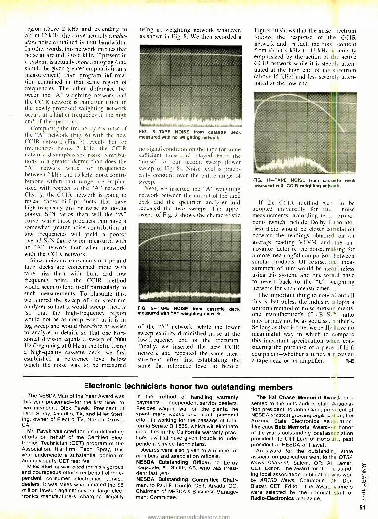
region above 2 kHz and extending to about 12 kHz, the curve actually empha- sizes noise contained in that bandwidth. In other words, this network implies that noise at around 3 to 6 kHz, if present in a system, is actually more annoying (and should be given greater emphasis in any measurement) than program informa- tion contained in that same region of frequencies. The other difference be- tween the "A" weighting network and the CCIR network is that attenuation in the newly proposed weighting network occurs at a higher frequency at the high end of the spectrum.
Comparing the frequency response of the "A" network (Fig. 6) with the new CCIR network (Fig. 7) reveals that for frequencies below 2 kHz, the CCIR network de- emphasizes noise contribu- tions to a greater degree than does the "A" network while for frequencies between 2 kHz and 15 kHz, noise contri- butions within that range are empha- sized with respect to the "A" network. Clearly, the CCIR network is going to reveal those hi -fi- products that have high- frequency hiss or noise as having poorer S/N ratios than will the "A" curve, while those products that have a somewhat greater noise contribution at low frequencies will yield a poorer overall S/N figure when measured with an "A" network than when measured with the CCIR network.
Since noise measurements of tape and tape decks are concerned more with tape hiss than with hum and low frequency noise, the CCIR method would seem to lend itself particularly to such measurements. To illustrate this, we altered the sweep of our spectrum analyzer so that it would sweep linearly (so that the high- frequency region would not be as compressed as it is in log sweep and would therefore be easier to analyze in detail), so that one hori- zontal division equals a sweep of 2000 Hz (beginning at 0 Hz at the left). Using a high -quality cassette deck, we first established a reference level below which the noise was to be measured
using no weighting network whatever, as shown in Fig. 8. We then recorded a
Figure 10 shows that the noise s >ectrum follows the response of the CCIR network and, in fact, the noise content from about 4 kHz to 12 kHz s actually emphasized by the action of the active CCIR network while it is steep!. atten- uated at the high end of the s >ectrum (above 15 kHz) and less severeb atten- uated at the low end.
FIG. 8 -TAPE NOISE from cassette deck measured with no weighting network.
no- signal condition on the tape for some sufficient time and played back the "noise" for our second sweep (lower sweep of Fig. 8). Noise level is practi- cally constant over the entire range of sweep.
Next, we inserted the "A" weighting network between the output of the tape deck and the spectrum analyzer and repeated the two sweeps. The upper sweep of Fig. 9 shows the characteristic
FIG. 9 -TAPE NOISE from cassette deck measured with "A" weighting network.
of the "A" network, while the lower sweep exhibits diminished noise at the low -frequency end of the spectrum. Finally, we inserted the new CCIR network and repeated the same mea- surement, after first establishing the same flat reference level as before.
FIG. 10 -TAPE NOISE from cassete deck measured with CCIR weighting network.
If the CCIR method were to be adopted universally for aucic noise measurements, according to i,s propo- nents (which include Dolby La,orato- ries) there would be closer con elation between the readings obtained on an average reading VTVM and f 1e an- noyance factor of the noise, mal..ng for a more meaningful comparisor letween similar products. Of course, an... mea- surement of hum would be meat ingless using this system, and one wcuid have to revert back to the "C" weighting network for such measurements.
The important thing to note about all this is that unless the industry a lopts a uniform method of noise measurements, one manufacturer's 60 -dB Sit' ratio may or may not be as good as an )ther's. So long as that is true, we realh" ) ave no meaningful way in which to c*Impare this important specification when con- sidering the purchase of a piece of hi -fi equipment- whether a tuner, a receiver, a tape deck or an amplifier. R -E
Electronic technicians honor two outstanding members The NESDA Man of the Year Award was
this year presented -for the first time -to two members; Dick Pavek, President of Tech Spray, Amarillo, TX, and Miles Sterl- ing, owner of Electro TV, Garden Grove, CA.
Mr. Pavek was cited for his outstanding efforts on behalf of the Certified Elec- tronics Technician (CET) program of the Association. His firm, Tech Spray, this year underwrote a substantial portion of an individual's CET test fee.
Miles Sterling was cited for his vigorous and courageous efforts on behalf of inde- pendent consumer electronics service dealers. It was Miles who initiated the $6 million lawsuit against several large elec- tronics manufacturers, charging illegality
in the method of handling warranty payments to independent service dealers. Besides waging war on the giants, he spent many weeks and much personal effort in working for the passage of Cali- fornia Senate Bill 568, which will eliminate inequities in the California warranty prac- tices law that have given trouble to inde- pendent service technicians.
Awards were also given to a number of members and association officers: NESDA Outstanding Officer, to Leroy Ragsdale, Ft. Smith, AR, who was Presi- dent last year. NESDA Outstanding Committee Chair- man, to Paul F. Dontje, CET, Arvada, CO, Chairman of NESDA's Business Manage- ment Commhttee.
The Hal Chase Memorial Award, pre- sented to the outstanding state Associa- tion president, to John Cioni, president of NESDA's fastest growing organizat on, the Arizona State Electronics Association. The Jack Betz Memorial Award --ir honor of the year's outstanding local asscciation president -to Cliff Lum of Hono uli, past president of HESDA of Hawaii.
An award for the outstandinc state association publication went to the OTSA News Channel, Salem, OR; Al _amer, CET, Editor. The award for the ou stand- ing local association publication w:s won by ARTSD News, Columbus, Of. Don Blazer, CET, Editor. The award nners were selected by the editorial staff of Radio -Electronics magazine.
51
www.americanradiohistory.com
Be the "New
Professional" in electronics
CREI trains you at home
for one of the most important
career levels in electronics plus offers you special
arrangements for engineering degrees
Advanced Electronics
Most people think there are only two levels of careers in electronics: the technician level and that of the degree engineer.
There is, however, a third and very im- portant level. It is that of the engineering technician or practical engineer. The growing importance of this career level has created what might well be called the "New Professional" in electronics.
If you look at the various levels of em- ployment in electronics, you will under- stand why this "New Professional" is so important.
The average technician is a person who has had vocational training in elec- tronics. He understands the basic prin- ciples of electronics so he can trouble- shoot, repair and maintain equipment. He usually works under close super- vision in performing his duties.
The engineer has college training in electronics. He usually supervises tech- nician personnel and is responsible for planning and developing of electronic equipment and systems. Frequently, however, engineers are more heavily trained in the scientific principles of electronics and less in their practical application.
The engineering technician, by con- trast, is a specialist in the practical appli- cation of electronics. His training usually consists of a two -year college program in electronic engineering technology. In many organizations, the engineering tech- nician handles several of the respon- sibilities of the degree engineer. He often has the title of engineer.
CREI programs are designed to give you at home the same level and depth of training you receive in a two -year col- lege program in electronic engineering technology. CREI programs are, in fact, more extensive than you will find in
many colleges. And CREI gives you the opportunity to specialize in your choice of the major fields of electronics.
Unique Design Lab CREI gives you both theory and prac- tical experience in circuit design with its Electronic Design Laboratory Program. The professional equipment included in
this program allows you to construct, test out and correct the circuits you de- sign until you have an effective circuit.
This Lab Program helps you under- stand advanced electronics. It also gives you practical experience in many other important areas of electronics, as in pro-
www.americanradiohistory.com
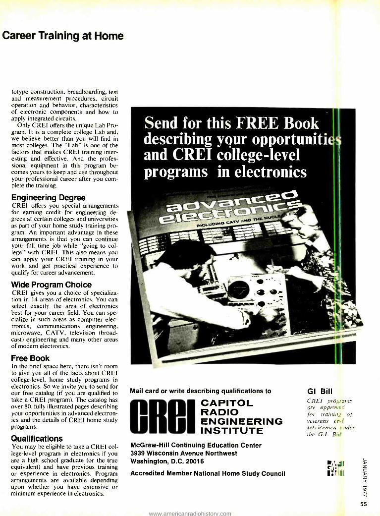
R
Career Training at Home
totype construction, breadboarding, test and measurement procedures, circuit operation and behavior, characteristics of electronic components and how to apply integrated circuits.
Only CREI offers the unique Lab Pro- gram. It is a complete college Lab and, we believe better than you will find in most colleges. The "Lab" is one of the factors that makes CREI training inter- esting and effective. And the profes- sional equipment in this program be- comes yours to keep and use throughout your professional career after you com- plete the training.
Engineering Degree CREI offers you special arrangements for earning credit for engineering de- grees at certain colleges and universities as part of your home study training pro- gram. An important advantage in these arrangements is that you can continue your full time job while "going to col- lege" with CREI. This also means you can apply your CREI training in your work and get practical experience to qualify for career advancement.
Wide Program Choice CREI gives you a choice of specializa- tion in 14 areas of electronics. You can select exactly the area of electronics best for your career field. You can spe- cialize in such areas as computer elec- tronics, communications engineering, microwave, CATV, television (broad- cast) engineering and many other areas of modern electronics.
Free Book In the brief space here, there isn't room to give you all of the facts about CREI college -level, home study programs in electronics. So we invite you to send for our free catalog (if you are qualified to take a CREI program). The catalog has over 80, fully illustrated pages describing your opportunities in advanced electron- ics and the details of CREI home study programs.
Qualifications You may be eligible to take a CREI col- lege -level program in electronics if you are a high school graduate (or the true equivalent) and have previous training or experience in electronics.. Program arrangements are available depending upon whether you have extensive or minimum experience in electronics.
Send for this FREE Book describing your opportunitio and CREI college-level programs in electronics
an -
Mail card or write describing qualifications to
I CAPITOL RADIO ENGINEERING INSTITUTE
McGraw -Hill Continuing Education Center 3939 Wisconsin Avenue Northwest Washington, D.C. 20016
Accredited Member National Home Study Council I:ihll
GI Bill CREI prai ems are approvgá for trainhig of veterans cr.t servicemen i ,rader the G.I. Bid
74':01
55
www.americanradiohistory.com
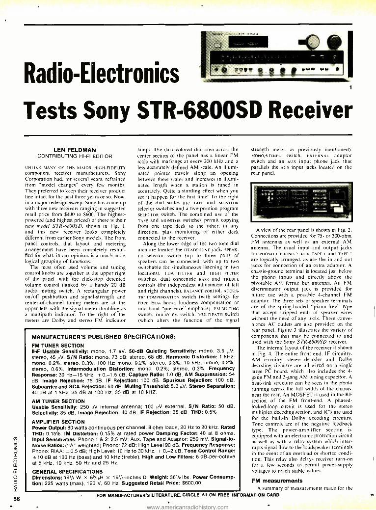
Radio -Electronics
Tests Sony STR- 6800SD Receiver
LEN FELDMAN CONTRIBUTING HI -FI EDITOR
UNLIKE MANY OF THE MAJOR HIGH- FIDELITY component receiver manufacturers, Sony Corporation had. for several years, refrained from "model changes" every few months. They preferred to keep their receiver product line intact for the past three years or so. Now, in a major redesign sweep, Sony has come up with three new receivers ranging in suggested retail price from $400 to $600. The highest - powered (and highest priced) of these is their new model STR -6800SD, shown in Fig. 1.
and this new receiver looks completely different from earlier Sony models. The front panel controls, dial layout and metering arrangement have been completely reshuf- fled for what, in our opinion, is a much more logical grouping of functions.
The most often used volume and tuning control knobs are together at the upper right of the panel, with the click -stop detented volume control flanked by a handy 20 dB audio muting switch. A rectangular power on /off pushbutton and signal- strength and center -of- channel tuning meters are at the upper left, with the signal meter doubling as
a multipath indicator. To the right of the meters are Dolby and stereo FM indicator
lamps. The dark -colored dial area across the center section of the panel has a linear FM scale with markings at every 200 kHz and a
less accurately defined AM scale. An illumi- nated pointer travels along an opening between these scales and increases in illumi- nated length when a station is tuned in accurately. Quite a startling effect when you see it happen for the first time! To the right of the dial scales are TAPE and MONITOR
selector switches and a five -position program SELECTOR switch. The combined use of the TAPE and MONITOR switches permit copying from one tape deck to the other. in any direction. plus monitoring of either deck connected to the receiver.
Along the lower edge of the two -tone dial area are located the HEADPHONE jack. SPEAK-
ER selector switch (up to three pairs of speakers can be connected. with up to two switchable for simultaneous listening in two locations). LOW FILTER and HIGH FILTER
switches, dual concentric BASS and TREBLE
controls (for independent adjustment of left and right channels). BALANCE control, ACOUS-
TIC COMPENSATION switch (with settings for fixed bass boost, loudness compensation or mid -hand "presence" emphasis). FM MUTING switch. DOLBY FM Switch. MULTIPATH Switch (which alters the function of the signal
MANUFACTURER'S PUBLISHED SPECIFICATIONS:
FM TUNER SECTION IHF Usable Sensitivity: mono, 1.7 µV. 50-dB Quieting Sensitivity: mono, 3.5 1.1.V;
stereo, 45 µV. S/N Ratio: mono, 73 dB; stereo, 68 dB. Harmonic Distortion: 1 kHz: mono, 0.2 %, stereo, 0.3 %. 100 Hz: mono, 0.2 %, stereo, 0.3 %. 10 kHz: mono, 0.2 %,
stereo, 0.6 %. Intermodulation Distortion: mono, 0.2 %; stereo, 0.3 %. Frequency Response: 30 Hz -15 kHz, + 0, -1.5 dB. Capture Ratio: 1.0 dB. AM Suppression: 54
dB. Image Rejection: 75 dB. IF Rejection: 100 dB. Spurious Rejection: 100 dB. Subcarrier and SCA Rejection: 60 dB. Muting Threshold: 5.0 1tV. Stereo Separation: 40 dB at 1 kHz; 35 dB at 100 Hz; 35 dB at 10 kHZ.
AM TUNER SECTION Usable Sensitivity: 250 µV internal antenna; 100 µV external. S/N Ratio: 50 dB. Selectivity: 35 dB. Image Rejection: 40 dB. IF Rejection: 35 dB THD: 0.5%
AMPLIFIER SECTION Power Output: 80 watts continuous per channel, 8 ohm loads, 20 Hz to 20 kHz. Rated THD: 0.15 %. IM Distortion: 0.15% at rated power Damping Factor: 40 at 8 ohms. Input Sensitivities: Phono 1 & 2: 2.5 mV; Aux, Tape and Adaptor: 250 mV. Signal -to- Noise Ratios: ( "A" weighted) Phono: 72 dB; High Level 90 dB. Frequency Response: Phono: RIAA: ±0.5 dB; High Level: 10 Hz to 30 kHz, + 0,-2 dB. Tone Control Range: ±10 dB at 100 Hz (bass) and 10 kHz (treble). High and Low Filters: 6 dB -per- octave at 5 kHz, 10 kHz, 50 Hz and 25 Hz.
GENERAL SPECIFICATIONS Dimensions: 19'/4 W x 69/16H x 161/4- inches D. Weight: 361/2 lbs. Power Consump- tion: 225 watts (max), 120 V, 60 Hz. Suggested Retail Price: $600.00.
strength meter, as previously mentioned), MONO /STEREO Switch, EXTERNAL adaptor switch and an AUX input phone jack that parallels the AUX input jacks located on the rear panel.
A view of the rear panel is shown in Fig. 2.
Connections are provided for 75- or 300 -ohm FM antennas as well as an external AM antenna. The usual input and output jacks for PHONO I, PHONO 2. AUX. TAPE I and TAPE 2
are logically arranged. as are the in and out jacks for connection of an extra adaptor. A chassis- ground terminal is located just below the phono inputs and directly above the pivotable AM ferrite bar antenna. An FM discriminator output jack is provided for future use with a possible 4- channel FM adaptor. The three sets of speaker terminals are of the spring- loaded "piano key" type that accept stripped ends of speaker wires without the need of any tools. Three conve- nience AC outlets are also provided on the rear panel. Figure 3 illustrates the variety of components that may be connected to and used with the Sony STR - 6800SD receiver.
The internal layout of the receiver is shown in Fig. 4. The entire front end, IF circuitry, AM circuitry, stereo decoder and Dolby decoding circuitry are all wired on a single large PC board, which also includes the 4- gang FM and 2 -gang AM tuning capacitor. A heat -sink structure can be seen in the photo running across the full width of the chassis, near the rear. An MOSFET is used in the RF section of the FM front -end. A phased - locked -loop circuit is used for the stereo multiplex decoding section, and IC's are used for the built -in Dolby decoding circuitry. Tone controls are of the negative feedback type. The power -amplifier section is
equipped with an electronic protection circuit as well as with a relay system which inter- rupts signal flow to the loudspeaker terminals in the event of an overload or shorted condi- tion. This relay also delays receiver turn -on for a few seconds to permit power- supply voltages to reach stable values.
FM measurements A summary of measurements made for the
FOR MANUFACTURER'S LITERATURE, CIRCLE 61 ON FREE INFORMATION CARD
www.americanradiohistory.com
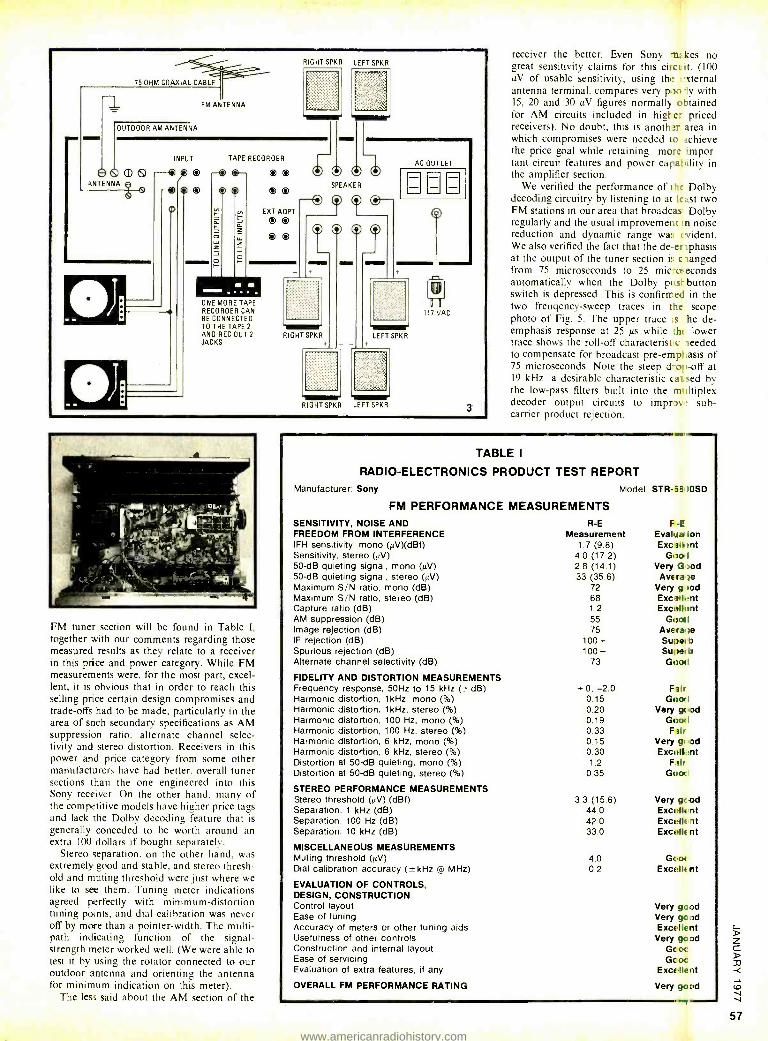
75-OHM COAXIAL CABLE
FM ANTENNA
OUTDOOR AM ANTENNA
RIGHT SPKR LEFT SPKR
mG NTENNA
INPUT
gyp® 1( O
TAPE RECORDER
O
o O O
EXT ADPT
O O
O O
ONE MORE TAPE RECORDER CAN BE CONNECTED TO THE TAPE 2
AND REC OUT 2
JACKS
SPEAKER
O O
RIGHT SPKR
O G
o
AC OUTLET
LEFT SPKR
RIGHT SPKR LEFT SPKR
117 'AC
3
FM tuner section will be found in Table I.
together with our comments regarding those measured results as they relate to a receiver in this price and power category. While FM measurements were, for the most part, excel- lent, it is obvious that in order to reach this selling price certain design compromises and trade -offs had to be made, particularly in the area of such secondary specifications as AM suppression ratio, alternate channel selec- tivity and stereo distortion. Receivers in this power and price category from some other manufacturers have had better, overall tuner sections than the one engineered into this Sony receiver. On the other hand, many of the competitive models have higher price tags and lack the Dolby decoding feature that is generally conceded to be worth around an extra 100 dollars if bought separately.
Stereo separation, on the other hand, was extremely good and stable. and stereo thresh- old and muting threshold were just where we like to see them. Tuning meter indications agreed perfectly with minimum- distortion tuning points, and dial calibration was never off by more than a pointer -width. The multi - path indicating function of the signal - strength meter worked well. (We were able to test it by using the rotator connected to our outdoor antenna and orienting the antenna for minimum indication on this meter).
The less said about the AM section of the
receiver the better. Even Sony nt:kes no great sensitivity claims for this circuit. (100 µV of usable sensitivity, using the external antenna terminal, compares very poo ly with 15, 20 and 30 IN figures normally obtained for AM circuits included in higher priced receivers). No doubt, this is anoth area in which compromises were needed lc .chieve the price goal while retaining more mpor- tant circuit features and power capa: 'ility in the amplifier section.
We verified the performance of the Dolby decoding circuitry by listening to at least two FM stations in our area that broadcas Dolby regularly and the usual improvement in noise reduction and dynamic range was t vident. We also verified the fact that the de erphasis at the output of the tuner section it. clanged from 75 microseconds to 25 mic- oaeconds automatically when the Dolby pull button switch is depressed. This is confirmed in the two freuqency -sweep traces in the scope photo of Fig. 5. The upper trace :s he de- emphasis response at 25 IJs while th, lower trace shows the roll -off characterist c Teeded to compensate for broadcast pre -emphasis of 75 microseconds. Note the steep d -op -off at 19 kHz -a desirable characteristic caused by the low -pass filters built into the multiplex decoder output circuits to imprw sub - carrier product rejection.
TABLE I
RADIO -ELECTRONICS PRODUCT TEST REPORT Manufacturer: Sony
FM PERFORMANCE SENSITIVITY, NOISE AND FREEDOM FROM INTERFERENCE IFH sensitivity, mono (1N)(dBf) Sensitivity, stereo (iV) 50-dB quieting signal, mono (µV) 50-dB quieting signal, stereo (pV) Maximum S/N ratio, mono (dB) Maximum S/N ratio, stereo (dB) Capture ratio (dB) AM suppression (dB) Image rejection (dB) IF rejection (dB) Spurious rejection (dB) Alternate channel selectivity (dB)
FIDELITY AND DISTORTION MEASUREMENTS Frequency response, 50Hz to 15 kHz (± dB) Harmonic distortion, 1kHz, mono ( %) Harmonic distortion, 1 kHz, stereo ( %) Harmonic distortion, 100 Hz, mono ( %) Harmonic distortion, 100 Hz, stereo ( %) Harmonic distortion, 6 kHz, mono ( %) Harmonic distortion, 6 kHz, stereo ( %) Distortion at 50 -dB quieting, mono ( %) Distortion at 50-dB quieting, stereo ( %)
STEREO PERFORMANCE MEASUREMENTS Stereo threshold (pV) (dBf) Separation, 1 kHz (dB) Separation, 100 Hz (dB) Separation, 10 kHz (dB)
MISCELLANEOUS MEASUREMENTS Muting threshold (uV) Dial calibration accuracy ( ±kHz @ MHz)
EVALUATION OF CONTROLS, DESIGN, CONSTRUCTION Control layout Ease of tuning Accuracy of meters or other tuning aids Usefulness of other controls Construction and internal layout Ease of servicing Evaluation of extra features, if any
OVERALL FM PERFORMANCE RATING
MEASUREMENTS
Model: STR -i8 )0SD
R -E Measurement
1.7 (9.8) 4.0 (17.2) 2.8 (14.1) 33 (35.6)
72 68 1.2 55 75
100+ 100+
73
+0, -2.0 0.15 0.20 0.19 0.33 0.15 0.30 1.2
0.35
3.3 (15.6) 44.0 42.0 33.0
4.0 0.2
F -E
Eval Ja ion Exc :Mont
Goof I
Very Gaod Avera to
Very tip wod
EXcaIl+ent Exc. Ihmt
Good Ave rap Superb Superb Good
F G,
Very G.
F
Very EXC
F
Gc
Very Exc. Exc, Exc,
Ge Exce
Very Very Exc
Very Gc Gc
Exc(
Very
Nil
loti ge'od od Nil
good rlle'nt tHr
soc
gcod elle nt elle nt elle rit
tIE nt
gc od gc od Ile nt gc od oc oc Ile nt
go od
www.americanradiohistory.com
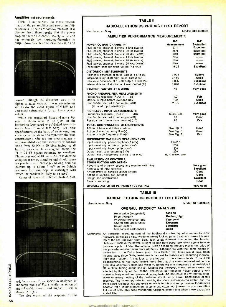
Amplifier measurements Table Il summarizes the measurements
made on the preamplifier and power amplifi- er sections of the ST'R- 6800SD receiver. It is
obvious from these results that the power amplifier section is conservatively rated and has extremely low harmonic -distortion at output power levels up to its rated value and
beyond. Though IM distortion was a bit higher at rated output. it was nevertheless still below the rated figure of 0.15`7 and decreased substantially for all lower power values.
While our measured hum -and -noise fig- ures in phono seem to be "just on the
borderline (compared to published specifica- tions). hear in mind that Sony lists these
specifications on the basis of an A- weighting curve (which tends to de- emphasize the hum contribution). whereas our measurement is
an unweighted one that measures wideband noise from 20 Hz to 20 kHz. including all hum components. In unweighted terms, the 71 to 72 dB figures obtained are excellent. Phono overload of 100 millivolts was deemed adequate if not outstanding and should cause
no problem with cartridges having nominal outputs up to about 5 mV or so (which accounts for most popular cartridges with which the receiver is likely to be used).
Range of bass and treble controls is plot-
ted, by means of our spectrum analyzer, in the scope photo of Fig. 6. while the action of the selectable low -cut and high -cut filters is
shown in Fig. 7.
We also measured the response of the
TABLE II
RADIO -ELECTRONICS PRODUCT TEST REPORT
Manufacturer: Sony Model
AMPLIFIER PERFORMANCE MEASUREMENTS
POWER OUTPUT CAPABILITY RMS power /channel, 8 -ohms, 1 kHz (watts) RMS power /channel, 8 -ohms, 20 Hz (watts) RMS power /channel, 8 -ohms, 20 kHz (watts) RMS power /channel, 4 -ohms, 1 kHz (watts) RMS power /channel, 4 -ohms, 20 Hz (watts) RMS power /channel, 4 -ohms, 20 kHz (watts) Frequency limits for rated output (Hz -kHz)
DISTORTION MEASUREMENTS Harmonic distortion at rated output, 1 kHz ( %) Intermodulation distortion, rated output ( %) Harmonic distortion at 1 watt output, 1 kHz ( %) Intermodulation distortion at 1 watt output ( %)
DAMPING FACTOR, AT 8 OHMS
PHONO PREAMPLIFIER MEASUREMENTS Frequency response (RIAA ± dB) Maximum input before overload (mV) Hum /noise referred to full output (dB)
(at rated input sensitivity).
HIGH LEVEL INPUT MEASUREMENTS Frequency response (Hz -kHz, ± _dB) Hum /noise referred to full output (dB) Residual hum /noise (min. volume) (dB)
TONAL COMPENSATION MEASUREMENTS Action of bass and treble controls Action of low frequency filter(s) Action of high frequency filter(s)
COMPONENT MATCHING MEASUREMENTS Input sensitivity, phono 1 /phono 2 (mV) Input sensitivity, auxiliary input(s) (mV) Input sensitivity, tape input(s) (mV) Output level, tape output(s) (mV) Output level, headphone jack(s) (V or mW)
EVALUATION OF CONTROLS, CONSTRUCTION AND DESIGN Adequacy of program source and monitor switching Adequacy of input facilities Arrangement of controls (panel layout) Action of controls and switches Design and construction Ease of servicing
OVERALL AMPLIFIER PERFORMANCE RATING
R -E Measurement
93.1 86.0 90.0 N/A N/A N/A
16 -25
0.028 0.115 0.025 0.020
40
1.0 100
71/72
8 -30, 3.0 88 90
See Fig. 7
See Fig. 8
See Fig. 8
2.5/2.5 250 250 250
N /A, 8 -10K ohm
STR- 6800SD
R -E Evaluation Excellent Excellent Excellent
Excellent
Superb Good
Excellent Excellent
Very good
Fair Good
Excellent
Very good Good Fair
Good Good Fall
Very good Excellent
Good Good
Excellent Good
Very good
TABLE III
RADIO -ELECTRONICS PRODUCT TEST REPORT
Manufacturer: Sony Model: STR- 6800SD
OVERALL PRODUCT ANALYSIS Retail price (suggested) $600.00 Price category Medium /high Price /performance ratio Very good Styling and appearance Excellent Sound quality Excellent Mechanical performance Good
Comments: An intelligent rearrangement of the traditional control layout common to most receivers, as well as a new, two -tone framed looking panel treatment makes this new top -of- the -line receiver from Sony look a bit different from either the familiar "blackout" look, or the newer, all -light colored front -panel look which seems to have
become popular of late. The included Dolby decoding circuitry makes the price of
this powerful receiver even more attractive, although we wish that some means of calibration of the Dolby levels (such as a built -in test tone) would have been
incorporated, since Dolby test -tones broadcast by stations are becoming increas- ingly less frequent. A first look at the insides of the chassis tends to be a bit disappointing, for the layout seems more like that of a mass -produced set, with a
great deal of circuitry all on one major PC board and a fully exposed and unshielded RF section -tuning gangs and all. Despite this, however, measurements were not
affected by this layout, and neither was actual performance. Power output is very
conservatively rated, and pre- conditioning tests did not result in any thermal shut- down or undue heating of the heat -sink structures or power transformer of this receiver. The tape -copy selector switch, the ACOUSTIC COMPENSATOR switch and the front -panel AUX input jack add extra versatility to this unit and provisions for an extra adaptor (for 4- channel decoders, graphic equalizers, etc.) mean that you can retain
full use of both other tape monitoring functions even if and when these extras are
added later.
www.americanradiohistory.com
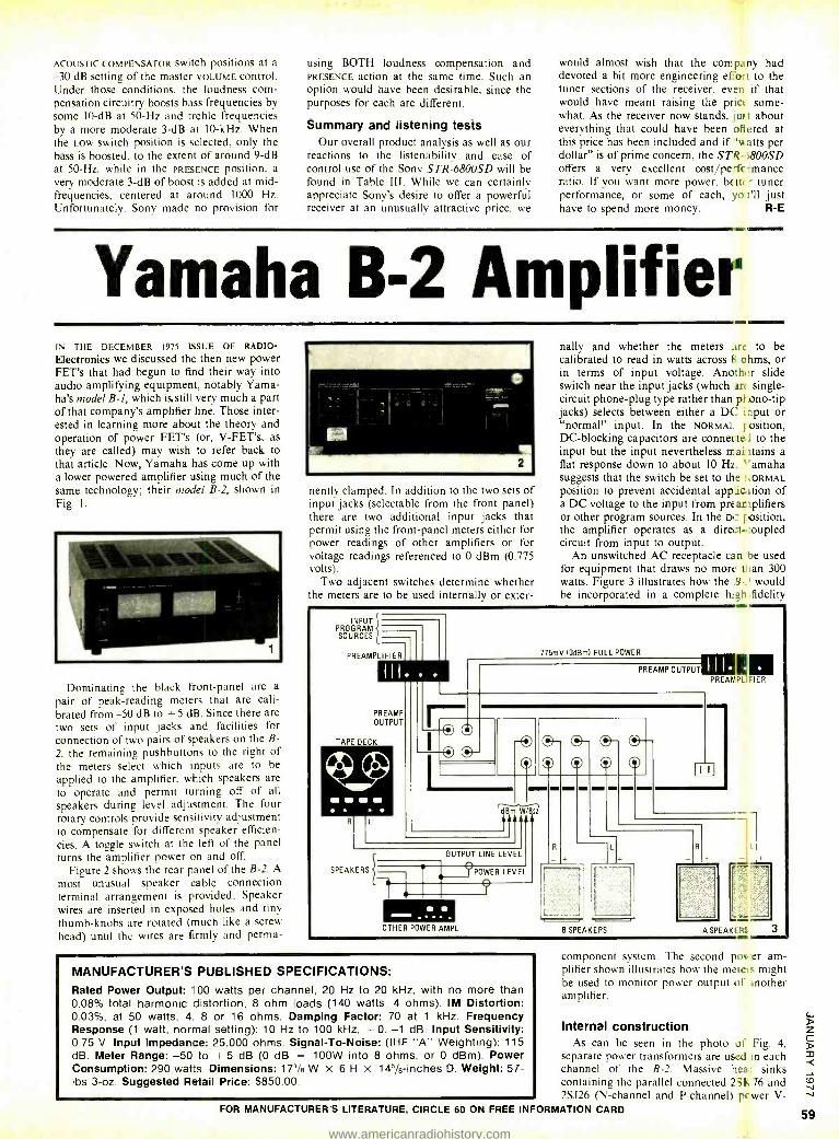
ACOUSTIC COMPENSATOR SwptCh positions at a
-30 dB setting of the master VOLUME control. Under those conditions, the loudness com- pensation circuitry boosts bass frequencies by some 10 -dB at 50 -Hz and treble frequencies by a more moderate 3 -dB at 10 -kHz. When the Low switch position is selected, only the bass is boosted. to the extent of around 9 -dB at 50 -Hz. while in the PRESENCE position, a very moderate 3 -dB of boost is added at mid - frequencies, centered at around 1000 Hz. Unfortunately. Sony made no provision for
using BOTH loudness compensation and PRESENCE action at the same time. Such an option would have been desirable, since the purposes for each are different.
Summary and listening tests Our overall product analysis as well as our
reactions to the listenability and ease of control use of the Sony STR- 6800SD will be found in Table III. While we can certainly appreciate Sony's desire to offer a powerful receiver at an unusually attractive price, we
would almost wish that the company had devoted a bit more engineering eUort to the tuner sections of the receiver, even if that would have meant raising the price some- what. As the receiver now stands, jus t about everything that could have been offered at this price has been included and if ̀ watts per dollar" is of prime concern, the STR - í8005D offers a very excellent cost /pe- fcrmance ratio. If you want more power. better tuner performance, or some of each, yo I'll just have to spend more money. R -E
ANN
Yamaha B -2 Amplifier IN THE DECEMBER 1975 ISSUE OF RADIO -
Electronics we discussed the then new power FET's that had begun to find their way into audio amplifying equipment, notably Yama- ha's model B -1, which is. still very much a part of that company's amplifier line. Those inter- ested in learning more about the theory and operation of power FET's (or, V- FET's, as they are called) may wish to refer back to that article. Now, Yamaha has come up with a lower powered amplifier using much of the same technology; their model B -2, shown in Fig. 1.
Dominating the black front -panel are a
pair of peak- reading meters that are cali- brated from -50 dB to +5 dB. Since there are two sets of input jacks and facilities for connection of two pairs of speakers on the B-
2. the remaining pushbuttons to the right of the meters select which inputs are to be applied to the amplifier. which speakers are to operate and permit turning off of all
speakers during level adjustment. The four rotary controls provide sensitivity adjustment to compensate for different speaker efficien- cies. A toggle switch at the left of the panel turns the amplifier power on and off.
Figure 2 shows the rear panel of the B -2. A
most unusual speaker cable connection terminal arrangement is provided. Speaker wires are inserted in exposed holes and tiny thumb -knobs are rotated (much like a screw head) until the wires are firmly and perma-
nently clamped. In addition to the two sets of input jacks (selectable from the front panel) there are two additional input jacks that permit using the front -panel meters either for power readings of other amplifiers or for voltage readings referenced to 0 dBm (0.775 volts).
Two adjacent switches determine whether the meters are to be used internally or exter-
NMI
nally and whether the meters are to be calibrated to read in watts across f, ohms, or in terms of input voltage. Anoth +:r slide switch near the input jacks (which art single - circuit phone -plug type rather than pl ono -tip jacks) selects between either a DC input or "normal" input. In the NORMAL position, DC- blocking capacitors are connected to the input but the input nevertheless mai stains a flat response down to about 10 H2. ''amaha suggests that the switch be set to the I:ORMAL position to prevent accidental appic,ltion of a DC voltage to the input from preamplifiers or other program sources. In the DC f osition, the amplifier operates as a direct -coupled circuit from input to output.
An unswitched AC receptacle ca n ne used for equipment that draws no mori than 300 watts. Figure 3 illustrates how the .9 -.' would be incorporated in a complete high fidelity
INPUT PROGRAM SOURCES
PREAMPLIFIER
PREAMP OUTPUT
TAPE DECK
775mV (OdBm) FULL POWER
PREAMP OUTPUTS PREANP_ EIER
SPEAKERS
o-0- o-
dBr m W/'.5t
till OUTPUT LINE LEVEL
POWER LEVEL
OTHER POWER AMPL B SPEAKERS
MANUFACTURER'S PUBLISHED SPECIFICATIONS: Rated Power Output: 100 watts per channel, 20 Hz to 20 kHz, with no more than 0.08% total harmonic distortion, 8 ohm loads (140 watts, 4 ohms). IM Distortion: 0.03 %, at 50 watts, 4. 8 or 16 ohms. Damping Factor: 70 at 1 kHz. Frequency Response (1 watt, normal setting): 10 Hz to 100 kHz, + 0, -1 dB. Input Sensitivity: 0.75 V. Input Impedance: 25,000 ohms. Signal -To- Noise: (IHF "A" Weighting): 115 dB. Meter Range: -50 to + 5 dB (0 dB = 100W into 8 ohms, or 0 dBm). Power Consumption: 290 watts. Dimensions: 171/e W x 6H x 145/s- inches D. Weight: 57- lbs 3 -oz. Suggested Retail Price: $850.00.
A SPEAKI F.. 3
component system. The second poa er am- plifier shown illustrates how the meters might be used to monitor power output of mother amplifier.
Internal construction As can be seen in the photo of Fig. 4,
separate power transformers are used in each channel of the B -1. Massive hea sinks containing the parallel connected 2-E 76 and 2SJ26 (N- channel and P- channel) power V-
FOR MANUFACTURER'S LITERATURE, CIRCLE 60 ON FREE INFORMATION CARD
www.americanradiohistory.com
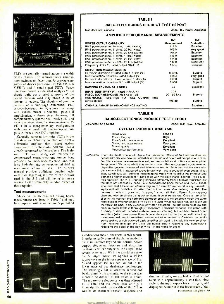
FET's are centrally located across the width of the chassis. The semiconductor comple- ment includes no fewer than 95 bipolar tran- sistors, 66 diodes (including LED's), 2 IC's, 8
V -FET's and 4 small -signal FET's. Space limitation prevents a detailed analysis of the circuit itself, but a brief summary of the circuit elements used may prove to be of interest to readers. The circuit configuration consists of a first -stage differential FET cascode- bootstrap circuit, a pre -driver stage with current- mirror differential push -pull amplification, a driver stage featuring full complementary- symmetrical push -pull, and an output stage using the aforementioned V- FET's in a complementary configuration with parallel push -pull direct -coupled out- puts to form a true DC amplifier.
Carefully matched low -noise FET's in the first stage are thermally coupled and form a
differential amplifier that insures against long -term drift in the center potential that is
directly connected to the speakers. The high - gain FET's used, along with temperature compensated constant -current source bias, provide a common -mode -rejection -ratio that is so high that the center -potential drift is maintained within 10 mV. The owner's manual provides additional detailed tech- nical data regarding the rest of the circuits used in the B -2 and will be of immense interest to the technically minded owner of this amplifier.
Test measurements Major test results obtained during bench
measurement are listed in Table I and may be compared with manufacturer's published
TABLE I
RADIO -ELECTRONICS PRODUCT TEST REPORT
Manufacturer. Yamaha Model B -2 Power Amplifier
AMPLIFIER PERFORMANCE MEASUREMENTS R -E R -E
POWER OUTPUT CAPABILITY Measurement Evaluation RMS power /channel, 8 -ohms, 1 kHz (watts) 112 5 Excellent RMS power /channel, 8 -ohms, 20 Hz (watts) 106.0 Very good RMS power /channel, 8 -ohms, 20 kHz (watts) 106.0 Excellent RMS power /channel, 4 -ohms, 1 kHz (watts) 146 0 Excellent RMS power /channel, 4 -ohms, 20 Hz (watts) 144.0 Excellent RMS power /channel, 4 -ohms, 20 kHz (watts) 142 0 Excellent Frequency limits for rated output (Hz -kHz) 10 -55 Excellent
DISTORTION MEASUREMENTS Harmonic distortion at rated output, 1 kHz ( %) 0.0035 Superb Intermodulation distortion, rated output ( %) 0.058 Very good Harmonic distortion at 1 watt output, 1 kHz ( %) 0.008 Superb Intermodulation distortion at 1 watt output ( %) 0.008 Superb
DAMPING FACTOR, AT 8 OHMS 75 Excellent
INPUT SENSITIVITY (For rated output, V) 0.75 FREQUENCY RESPONSE (Hz- kHz. ±1 dB) DC -90 kHz Superb HUM /NOISE REFERRED TO FULL OUTPUT (dB) (unweighted) 108 dB Superb
OVERALL AMPLIFIER PERFORMANCE RATING Excellent
TABLE II
RADIO- ELECTRONICS PRODUCT TEST REPORT Manufacturer: Yamaha Model B -2 Power Amplifier
OVERALL PRODUCT ANALYSIS Retail price Price category Price /performance ratio Styling and appearance Sound quality Mechanical performance
$850.00 High Excellent Very good Excellent Very good
Comments: There are those who would argue that laboratory testing of an amplifier does not necessarily disclose how that amplifier will sound and how it will compare with other amplifiers whose measurements equal, surpass or fall short of those of an amplifier being tested. We must admit that we, too, have often encountered such seeming disparities between measured and listened -to results. Such was not the case with the Yamaha B -2. It measured exceptionally well -and it sounded even better. What issue we will take with some of the statements made with regard to this product (and Yamaha's higher powered B -1) have to do with the claim that it "sounds" like a tube - type amplifier. The V -FET certainly behaves differently from a bipolar transistor, but that does not necessarily mean that it duplicates the performance of a triode. Those who insist that tube -sound offers a degree of "warmth" not found in any transistor equipment will probably not alter their opinion even after hearing the B -2. The manner in which it goes into "clipping" is not all that different from clipping observed with amplifiers using conventional bipolar transistors. Once an amplifier clips in this manner, the harmonic distortion products will be pretty much the same regardless of whether bipolar or V -FET's are used. What has been reduced to almost the vanishing point is any evidence of "notch distortion ", so that listening at low and medium power levels is thoroughly transparent. Transient response, evaluated with a variety of difficult recorded material, was outstanding, but we have heard other amplifiers (which use conventional bipolar devices) that do just as well once they have been designed for excellent risetime and wide bandwidth. Certainly, the audio purist seeking a high -powered basic amplifier will want to include this new amplifier from Yamaha amongst the units auditioned before reaching any conclusions regarding the place of the power V -FET in the world of audio.
specifications shown elsewhere in this report. In order to study some of the claims made by the manufacturer beyond the normal power output, frequency response and distortion measurements, we subjected the amplifier to several other tests. With the amplifier set to the DC input mode, we applied a 10 -Hz squarewave to the input (upper trace of Fig. 5) and applied the resultant output to the lower trace of our dual -trace oscilloscope. The amazingly flat squarewave reproduced by the amplifier is so similar to the input that it would be difficult to tell which is which. The squarewave frequency was then adjusted to 10 kHz, and the lower trace of Fig. 6 illustrates the wide bandwidth of the B -2 as well as its excellent transient response and
risetime. Finally, we applied a 10 -kHz tone burst with approximately a one -third duty cycle to the input (upper trace of Fig. 7) and displayed the output in the lower trace of that
continued on page 78
www.americanradiohistory.com
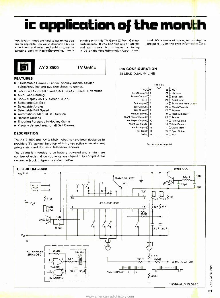
ic application of the month Application notes are hard to get unless you are an engineer. So we've decided to try an experiment and select and publish some in- teresting ones in Radio -Electronics. We're
starting with this TV Game IC from General Instruments. If you find this one of interest and want more, let us know by circling #105 on the Free Information Card. If you
AY -3 -3500 TV GAME
FEATURES 6 Selectable Games - Tennis, hockey /soccer, squash. pelota /practice and two rifle shooting games.
625 Line (AY -3 -8500) and 525 Line (AY -3- 8500 -1) versions. Automatic Scoring Score display on T.V. Screen, 0 to 15.
Selectable Bat Size Selectable Angles
in Selectable Ball Speed Automatic or Manual Ball Service Realism Sounds Shooting Forwards in Hockey Game Visually defined area for all Ball Games.
DESCFIPTION
The AY -3 -8500 and AY- 3- 8500 -1 circuits have been designed to provide a TV 'games' function which gives active entertainment using a standard domestic television receiver.
The circuit is intended to be battery powered and a minimum number of external components are required to complete the system. A block diagram is shown below.
think it's a waste of space, tell us that by circling #110 on the Free Informatif n Card.
PIN CONFIGURATION 28 LEAD DUAL IN LINE
NC
Vss (Ground) Sound Output
Vcc Ball Angles
Ball Output Ball Speed
Manual Serve
Right Player Output Left Player Output
Right Bat Input
Left Bat Input
Bat Size
'NC
Top View
1 2
3
4
5
6
7
8
9
10
11
12
13
14
28
27
26
25
24
23
22
21
20
19
18
17
16
15
NC' Hit Input
Shot Input
Reset Input
Score and Field Of tp I
Pelota/Practice
Squash
Hockey /Soccer Tennis
Rifle Game 2
Rifle Game 1
Clock Input
Sync Output NC
'Do not use as tie point.
BLOCK DIAGRAM vcc o
RIFLE CIRCUIT
FIG 1
= 10µF
ySS
1510 /' e s2
2W
2N2222
Ia o
GAME SELECT
\ o-
T
28
AY-3-8500/8500-1
15K
0.2pF
ALTERNATE 12MS2
2MHz OSC.
5.6K
CRYSTAL 2.00 MHz
/4(4001)
4 6
30pfT 30p1
1_2r'/.(4011)
4072
2'
2MHz OSC.
90µH
T 75pF
4072
5100 3300 51052
SYNC SPACE -1 H-
1K
TO MODULATOR
2200
t0K
T 5pF
*NORMALLY CLO3EJ
www.americanradiohistory.com
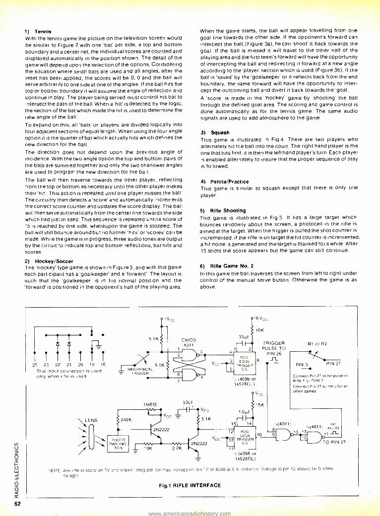
1) Tennis With the tennis game the picture on the television screen would be similar to Figure 2 with one 'bat' per side, a top and bottom boundary and a center net, the individual scores are counted and
displayed automatically in the position shown. The detail of the game will depend upon the selection of the options. Considering the situation where small bats are used and all angles, after the reset has been applied, the scores will be 0, 0 and the ball will serve arbitrarily to one side at one of the angles. If the ball hits the top or bottom boundary it will assume the angle of reflection and continue in play. The player being served must control his bat to intersect the path of the ball. When a'hit' is detected by the logic, the section of the bat which made the hit is used to determine the new angle of the ball.
To expand on this, all 'bats' or 'players' are divided logically into four adjacent sections of equal length. When using the four angle option it is the quarter of bat which actually hits which defines the new direction for the ball.
The direction does not depend upon the previous angle of incidence. With the two angle option the top and bottom pairs of the bats are summed together and only the two shallower angles are used to program the new direction for the ball.
The ball will then traverse towards the other player, reflecting from the top or bottom as necessary until the other player makes their 'hit'. This action is repeated until one player misses the ball. The circuitry then detects a 'score' and automatically increments the correct score counter and updates the score display. The ball will then serve automatically from the center line towards the side which had just missed. This sequence is repeated until a score of 15 is reached by one side, whereupon the game is stopped. The ball will still bounce around but no further 'hits' or'scores' can be made. While the game is in progress, three audio tones are output by the circuit to indicate top and bottom reflections, bat hits and scores.
2) Hockey /Soccer The 'hockey' type game is shown in Figure 3, and with this game each participant has a 'goalkeeper' and a 'forward'. The layout is
such that the 'goalkeeper' is in his normal position and the 'forward' is positioned in the opponent's half of the playing area.
When the game starts, the ball will appear travelling from one goal line towards the other side. If the opponent's forward can intercept the ball, (Figure 3a), he can 'shoot' it back towards the goal. If the ball is missed it will travel to the other half of the playing area and the first team's forward will have the opportunity of intercepting the ball and redirecting it forward at a new angle according to the 'player' section which is used, (Figure 3b). If the ball is 'saved' by the 'goalkeeper' or it reflects back from the end boundary, the same forward will have the opportunity to inter- cept the outcoming ball and divert it back towards the 'goal.
A 'score' is made in the 'hockey' game by 'shooting' the ball through the defined goal area. The scoring and game control is
done automatically as for the tennis game. The same audio signals are used to add atmosphere to the game.
3) Squash This game is illustrated in Fig.4. There are two players who alternately hit the ball into the court. The right hand player is the one that hits first, it is then the left hand player's turn. Each player is enabled alternately to insure that the proper sequence of play is followed.
4) Pelota /Practice This game is similar to squash except that there is only one
player.
5) Rifle Shooting This game is illustrated in Fig.5. It has a large target which bounces randomly about the screen, a photocell in the rifle is
aimed at the target. When the trigger is pulled the shot counter is
incremented, if the rifle is on target the hit counter is incremented, a hit noise is generated and the target is blanked fora while. After 15 shots the score appears but the game can still continue.
6) Rifle Game No. 2
In this game the ball traverses the screen from left to right under control of the manual serve button. Otherwise the game is as
above.
25 23 22 21 20 19 18
This input connection is used only when rifle is used
LENS
/
'vcc
5.1 K CMOS 4011
1
51K MECHANICAL
TRIGGER
1MEG
240K
PHOTO DARLING
TON
50uf
2N2222
10K 22K
VCC
5.1 K
V_
16vcc
4 1 r
µf2
POS 3 EDGE
TRIGGER 5 SS
10K
TRIGGER PULSE TO
PIN 26 - R1 or R2
6
2 (4098 0 14528CL)
Q VGc
15K
1.0pf
15j 14
VCC 2N2222
12 POS EDGE
TRIGGER SS
11
10
PIN 3 PIN 27
Connect Pin 27 to hit pulse in
Rifle 1 or Rifle 2
Connect Pin 27 to Pin 3 tor all
other games
'.(4011) 8
72 (4098 o = 14528CL)
..401 HIT
' ( 1
) PULSE 10 13 \ 1111_
® TO PIN 27
NOTE: Aim rifle at score on TV and adjust 1 meg pot. for max. voltage on pin 12 of 4098 at 6 ft. distance. Voltage at pin 12 should be 0 when
no light.
Fig.1 RIFLE INTERFACE
www.americanradiohistory.com
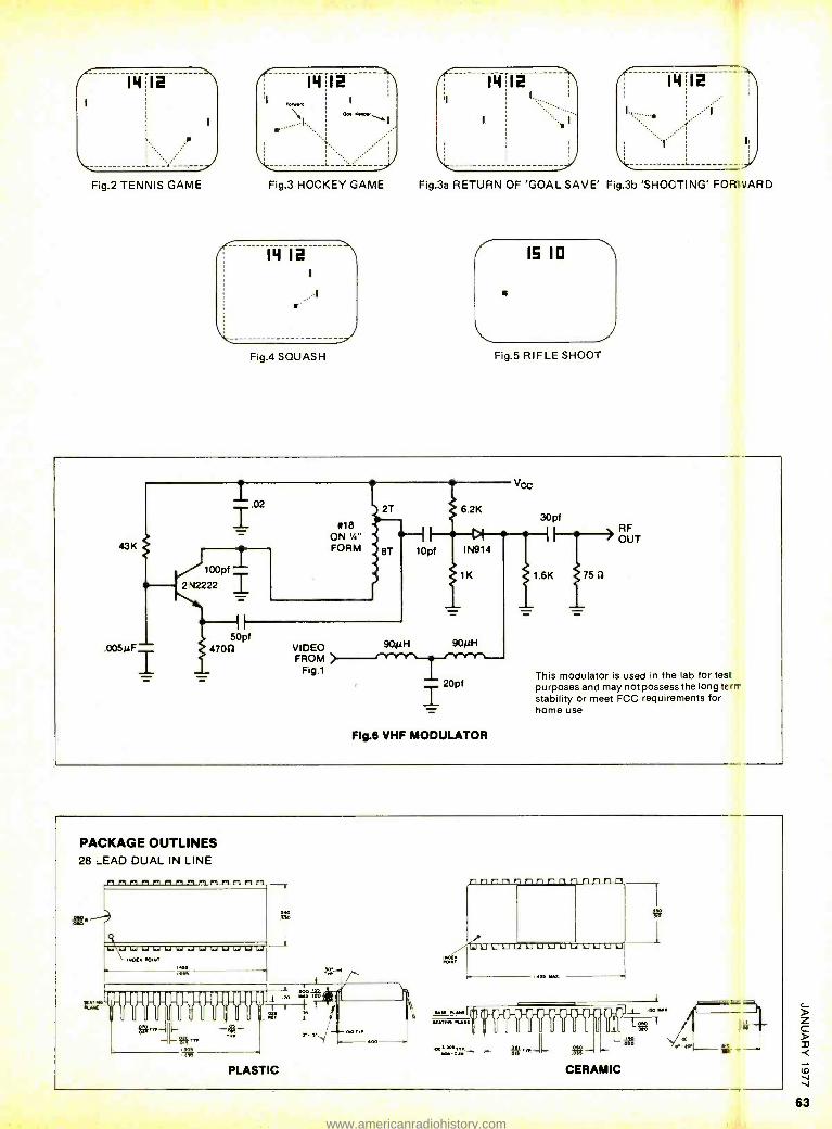
14
Fig.2 TENNIS GAME
14
Fig.3 HOCKEY GAME Fig.3a RETURN OF 'GOAL SAVE' Fig.3b 'SHOOTING' FOR',VARD
Fig.4 SQUASH Fig.5 RIFLE SHOOT
43K
.005µF-
.02 I 100pf
2'.N2222 I #18
ON '/." FORM
2T 6.2K
1 DI 8T 10pf IN914
1K
50pf 4700 VIDEO
FROM FIg.1
90µH 90µH
20pí
FIg.6 VHF MODULATOR
VCC
30pf
(i
1.6K 75 i2
RF OUT
This modulator is used in the lab for tes purposes and may not possess the long te
stability or meet FCC requirements for home use.
PACKAGE OUTLINES 28 LEAD DUAL IN LINE
111111111111,1111 rrrrrr" W40
PLASTIC
400
á
°°,=.: - se... -l- If- - `ss CERAMIC
, í Ya _.
rn
www.americanradiohistory.com
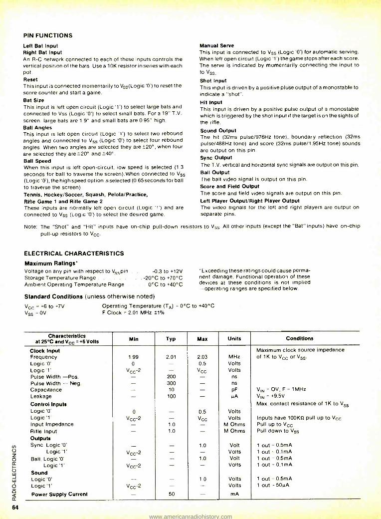
PIN FUNCTIONS
Left Bat Input Right Bat Input An R -C network connected to each of these inputs controls the vertical position of the bats. Use a 10K resistor in series with each pot. Reset This input is connected momentarily to Vss(Logic'0') to reset the score counter and start a game.
Bat Size This input is left open circuit (Logic '1') to select large bats and connected to Vss (Logic '0') to select small bats. For a 19" T.V.
screen, large bats are 1.9" and small bats are 0.95" high. Ball Angles This input is left open circuit (Logic '1') to select two rebound angles and connected to Vss (Logic '0') to select four rebound angles. When two angles are selected they are +_20 °, when four are selected they are ±20° and ±-40°.
Ball Speed When this input is left open- circuit, low speed is selected (1.3
seconds for ball to traverse the screen).When connected to Vss
(Logic '0'), the high speed option is selected (0.65 seconds for ball to traverse the screen). Tennis, Hockey /Soccer, Squash, Pelota /Practice, Rifle Game 1 and Rifle Game 2
These inputs are normally left open circuit (Logic '1') and are connected to Vss (Logic '0') to select the desired game.
Manual Serve This input is connected to Vss (Logic '0') for automatic serving. When left open circuit (Logic '1') the game stops after each score. The serve is indicated by momentarily connecting the input to to Vss.
Shot Input This input is driven by a positive pluse output of a monostable to indicate a "shot ".
Hit Input This input is driven by a positive pulse output of a monostable which is triggered by the shot input if the target is on the sights of the rifle.
Sound Output The hit (32ms pulse /976Hz tone), boundary reflection (32ms pulse /488Hz tone) and score (32ms pulse /1.95Hz tone) sounds are output on this pin.
Sync Output The T.V. vertical and horizontal sync signals are output on this pin.
Ball Output The ball video signal is output on this pin. Score and Field Output The score and field video signals are output on this pin.
Left Player Output /Right Player Output The video signals for the left and right players are output on separate pins.
Note: The "Shot" and "Hit" inputs have on -chip pull -down resistors to Vss. All other inputs (except the "Bat" inputs) have on -chip pull -up resistors to Vcc.
ELECTRICAL CHARACTERISTICS
Maximum Ratings" Voltage on any pin with respect to Vss pin . . -0.3 to +12V Storage Temperature Range -20 °C to +70 °C Ambient Operating Temperature Range . . . 0 °C to +40 °C
Standard Conditions (unless otherwise noted)
Vcc=+6to+7V Vss = OV
'Exceeding these ratings could cause perma- nent damage. Functional operation of these devices at these conditions is not implied -operating ranges are specified below.
Operating Temperature (TA) = 0 °C to +40 °C F Clock = 2.01 MHz t1%
Characteristics at 25°C and Vcc = +6 Volts Min Typ Max Units Conditions
Clock Input Maximum clock source impedance Frequency 1.99 2.01 2.03 MHz of 1K to Vcc or Vss.
Logic '0' 0 - 0.5 Volts Logic '1' Vcc -2 - Vcc Volts Pulse Width -Pos. - 200 - ns
Pulse Width - Neg. - 300 - ns Capacitance - 10 - pF VIN = OV, F = 1MHz Leakage - 100 - gA VIN = +9.5V
Control Inputs Max. contact resistance of 1K to Vss
Logic '0' 0 - 0.5 Volts Logic '1' Vcc-2 - Vcc Volts Inputs have 100KS2 pull up to Vcc Input Impedance - 1.0 - M Ohms Pull up to Vcc Rifle Input - 1.0 - M Ohms Pull down to Vss
Outputs Sync. Logic '0' - - 1.0 Volt 1 out = 0.5mA
Logic '1' Vcc -2 - - Volts 1 out = 0.1mA Ball. Logic '0' - - 1.0 Volt 1 out = 0.5mA
Logic '1' Vcc -2 - - Volts 1 out = 0.1 mA
Sound Logic '0' - - 1.0 Volts 1 out = 0.5mA Logic '1' Vcc -2 - - Volts 1 out = 50µA
Power Supply Current - 50 - mA
www.americanradiohistory.com
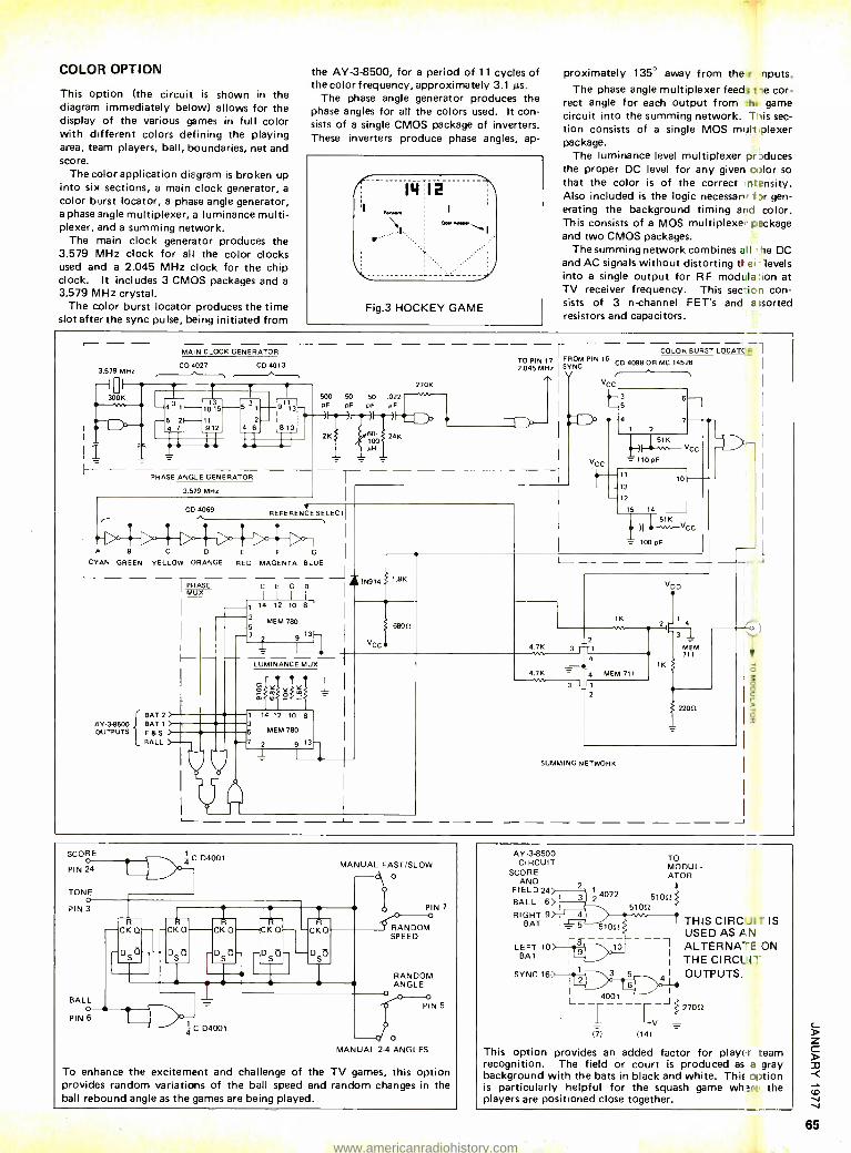
COLOR OPTION
This option (the circuit is shown in the diagram immediately below) allows for the display of the various games in full color with different colors defining the playing area, team players, ball, boundaries, net and score.
The color application diagram is broken up into six sections, a main clock generator, a
color burst locator, a phase angle generator, a phase angle multiplexer, a luminance multi- plexer, and a summing network.
The main clock generator produces the 3.579 MHz clock for all the color clocks used and a 2.045 MHz clock for the chip clock. It includes 3 CMOS packages and a
3.579 MHz crystal. The color burst locator produces the time
slot after the sync pulse, being initiated from
the AY -3 -8500, for a period of 11 cycles of the color frequency, approximately 3.1 As.
The phase angle generator produces the phase angles for all the colors used. It con- sists of a single CMOS package of inverters. These inverters produce phase angles, ap-
14I2
0.0.Y.No
Fig.3 HOCKEY GAME
proximately 135° away from the r inputs. The phase angle multiplexer feeds Ile cor-
rect angle for each output from thE' game circuit into the summing network. T lis sec- tion consists of a single MOS mull plexer package.
The luminance level multiplexer pr 3duces the proper DC level for any given color so that the color is of the correct ntensity. Also included is the logic necessary f )r gen- erating the background timing and color. This consists of a MOS multiplexer package and two CMOS packages.
The summing network combines all he DC and AC signals without distorting ttei levels into a single output for RF modula :ion at TV receiver frequency. This sec- :io'1 con- sists of 3 n-channel FET's and a;sorted resistors and capacitors.
3.579 MHz
MAIN CLOCK GENERATOR
CD 4027 CD 4013
30
1_
500 50 50 .022 pf pF pF pF
2K
)I t) 60- 100 I4I
4K
270K
PHASE ANGLE GENERATOR
3.579 MHz
COLOR BURST LOCATC P
TO PIN 7 FROM PIN 16
2.045 MHz I SYNC CD 4098012 MC 14528
V
CD 4069 REFERENCE SELECT;
A B C E G
CYAN GREEN YELLOW ORANGE RED MAGENTA BLUE -
AY -38500 OUTPUTS
BAT 2) BAT 1 ) F &S >
BALL )
PHASE MUX
I I I
CEGB 1 14 12 10 8
3 MEM 780 5 7
1 9 1
IN914 1.8K
vCC
6805
LUMINANCE MUX
1 14 12 10 8 3 5 MEM 780
7 2 9 13
1
1
11
13
12
15 14
10
4.7 K 3
4.7K
4
3 111
VDD
1K 1
vw
MEM 711
iK
T
3
MEM 711
220E
SUMMING NETWORK
SCORE
PIN 2O 4 ( I
TONE
1
O PIN 3
R CK Q-
D4001
- 4- -CK Q-CK Q
D
BALL PING
DIS
IT
C D4001
CK Q
D
CKQ
-D
MANUAL FAST /SLOW O
Ó PIN 7 a
RANDOM SPEED
RANDOM ANGLE 0 0
PIN 5
q o MANUAL 2-4 ANGLES
To enhance the excitement and challenge of the TV games, this option provides random variations of the ball speed and random changes in the ball rebound angle as the games are being played.
AY -3-8500 CIRCUIT
SCORE AND
FIELD 24
BALL 6
2 3
2 4072 51012
TO MODUL- ATOR
RIGHT 9 I 4 BAT 5
r- 8 LEFT 10 BAT
SYNC 16
I 4001
5100
10
171
+V
114)
-
THIS CIRC. USED AS P.
ALTERNAT THE CIRCU OUTPUTS.
ITIS N E ON 17'
27012
This option provides an added factor for playEl recognition. The field or court is produced as background with the bats in black and white. This is particularly helpful for the squash game wha players are positioned close together.
team a gray option rE the
www.americanradiohistory.com
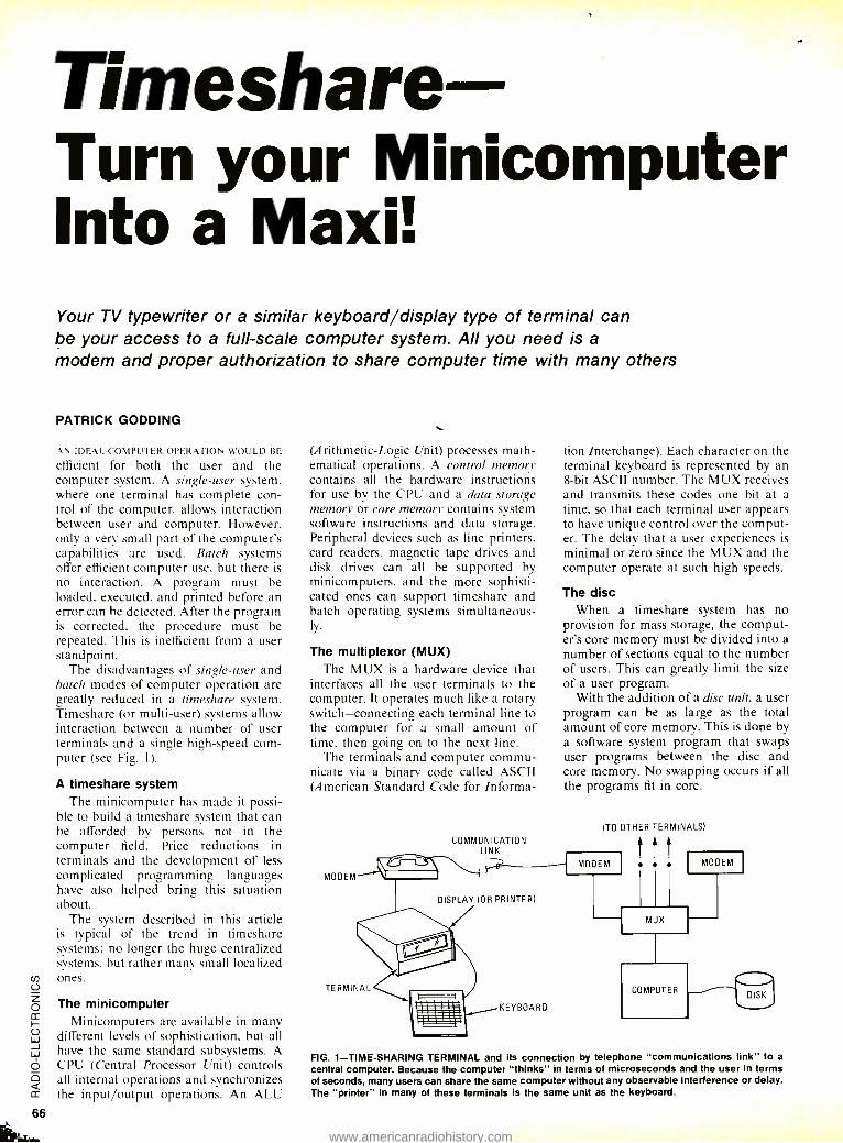
Timeshare Turn your Minicomputer Into a Maxi! Your TV typewriter or a similar keyboard /display type of terminal can be your access to a full -scale computer system. All you need is a
modem and proper authorization to share computer time with many others
PATRICK GODDING
AN IDEAL EOM PE FLR OPERATION WOULD RE
efficient for both the user and the computer system. A single -user system. where one terminal has complete con- trol of the computer. allows interaction between user and computer. However. only a very small part of the computer's capabilities are used. Batch systems offer efficient computer use, but there is
no interaction. A program must be loaded. executed. and printed before an error can be detected. After the program is corrected. the procedure must be repeated. This is inefficient from a user standpoint.
The disadvantages of single -user and batch modes of computer operation are greatly reduced in a timeshare system. Timeshare (or multi -user) systems allow interaction between a number of user terminals and a single high -speed com- puter (see Fig. I).
A timeshare system The minicomputer has made it possi-
ble to build a timeshare system that can be afforded by persons not in the computer field. Price reductions in terminals and the development of less complicated programming languages have also helped bring this situation about.
The system described in this article is typical of the trend in timeshare systems: no longer the huge centralized systems, but rather many small localized ones.
The minicomputer Minicomputers are available in many
different levels of sophistication. but all have the same standard subsystems. A CPU (Central Processor Unit) controls all internal operations and synchronizes the input /output operations. An ALU
(Arithmetic -Logic Unit) processes math- ematical operations. A control memory contains all the hardware instructions for use by the CPU and a data storage memory or core memory contains system software instructions and data storage. Peripheral devices such as line printers. card readers. magnetic tape drives and disk drives can all he supported by minicomputers, and the more sophisti- cated ones can support timeshare and batch operating systems simultaneous- ly.
The multiplexor (MUX) The MUX is a hardware device that
interfaces all the user terminals to the computer. It operates much like a rotary switch -connecting each terminal line to the computer for a small amount of time. then going on to the next line.
The terminals and computer commu- nicate via a binary code called ASCII (American Standard Code for Informa-
MODEM
COMMUNICATION LINK
DISPLAY (OR PRINTER)
tion Interchange). Each character on the terminal keyboard is represented by an 8 -bit ASCII number. The MUX receives and transmits these codes one bit at a time. so that each terminal user appears to have unique control over the comput- er. The delay that a user experiences is minimal or zero since the MUX and the computer operate at such high speeds.
The disc When a timeshare system has no
provision for mass storage, the comput- er's core memory must be divided into a number of sections equal to the number of users. This can greatly limit the size of a user program.
With the addition of a disc unit, a user program can be as large as the total amount of core memory. This is done by a software system program that swaps user programs between the disc and core memory. No swapping occurs if all the programs fit in core.
(TO OTHER TERMINALS)
I MODEM MODEM I
MUX
COMPUTER DISK
FIG. 1- TIME -SHARING TERMINAL and its connection by telephone "communications link" to a
central computer. Because the computer "thinks" in terms of microseconds and the user in terms of seconds, many users can share the same computer without any observable interference or delay. The "printer" in many of these terminals is the same unit as the keyboard.
www.americanradiohistory.com
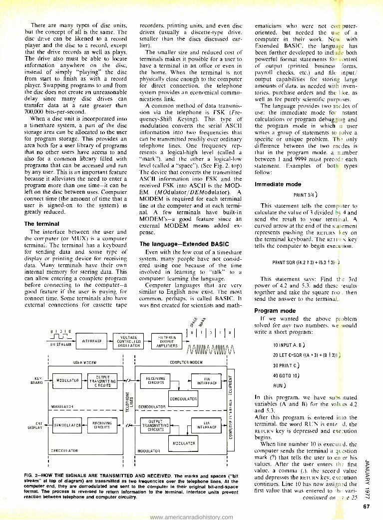
There are many types of disc units, but the concept of all is the same. The disc drive can be likened to a record player and the disc to a record, except that the drive records as well as plays. The drive also must be able to locate information anywhere on the disc, instead of simply "playing" the disc from start to finish as with a record player. Swapping programs to and from the disc does not create an unreasonable delay since many disc drives can transfer data at a rate greater than 700,000 bits -per- second.
When a disc unit is incorporated into a timeshare system, a part of the disc storage area can be allocated to the user for program storage. This provides an area both for a user library of programs that no other users have access to and also for a common library filled with programs that can be accessed and run by any user. This is an important feature because it alleviates the need to enter a program more than one time -it can be left on the disc between uses. Computer connect time (the amount of time that a user is signed -on to the system) is greatly reduced.
The terminal The interface between the user and
the computer (or MUX) is a computer terminal. The terminal has a keyboard for sending data and some type of display or printing device for receiving data. Many terminals have their own internal memory for storing data. This can allow entering a complete program before connecting to the computer -a good feature if the user is paying for connect time. Some terminals also have external connections for cassette tape
0 1 0 1 0
BIT STREAM INTERFACE
USER MODEM
recorders. printing units, and even disc drives (usually a discette -type drive, smaller than the discs discussed ear- lier).
The smaller size and reduced cost of terminals makes it possible for a user to have a terminal in an office or even in the home. When the terminal is not physically close enough to the computer for direct connection. the telephone system provides an economical commu- nications link.
A common method of data transmis- sion via the telephone is FSK (Fre- quency -Shift Keying). This type of modulation converts the serial ASCII information into two frequencies that can be transmitted readily over ordinary telephone lines. One frequency rep- resents a logical -high level (called a "mark "). and the other a logical -low level (called a "space "). (See Fig. 2. top) The device that converts the transmitted ASCII information into FSK and the received FSK into ASCII is the MOD- EM (MOdulator /DEModulator). A MODEM is required for each terminal line at the computer and at each termi- nal. A few terminals have built -in MODEM's -a good feature since an external MODEM means added ex- pense.
The language- Extended BASIC Even with the low cost of a timeshare
system. many people have not consid- ered using one because of the time involved in learning to "talk" to a computer: learning the language.
Computer languages that are very similar to English now exist. The most common, perhaps. is called BASIC. It was first created for scientists and math-
VOLTAGE CONTROLLED OSCILLATOR
KEY BOARD
MODULATOR
MODULATOR
OUTPUT TRANSMITTING
CIRCUITS
CRT,,_ DISPLAY
DEMODULATOR
DEMODULATOR
RECEIVING CIRCUITS
z w aZ LLI
FILTERS& OUTPUT
AMPLIFIERS
` e 5 P 1 0 1 1 1 1 1 I 0
COMPUTER MODEM
1 V `
RECEIVING CIRCUITS
DEMODULATOR
EIA INTERFACE
DEMODULATOR
f- OUTPUT TRANSMITTING
CIRCUITS
MODULATOR
EIA INTERFACE
t
MODULATOR
y
w
CO
FIG. 2 -HOW THE SIGNALS ARE TRANSMITTED AND RECEIVED. The marks and spaces ( "bit stream" at top of diagram) are transmitted as two frequencies over the telephone lines. At the computer end, they are demodulated and sent to the computer in their original bit -and -space format. The process is reve -sed to return information to the terminal. Interface units prevent reaction between telephone and computer circuitry.
ematicians who were not con puter- oriented. but needed the u.,e of a computer in their work. Now with Extended BASIC. the language has been further developed to include both powerful format statements for control of output (printed business forms, payroll checks, etc.) and file input/ output capabilities for storing large amounts of data. as needed with inven- tories, purchase orders and the like. as well as for purely scientific purposes.
The language provides two in( des of use: the immediate mode for nstant calculations or program debugging and the program mode in which ;t user writes a group of statements to solve a specific or unique problem. Th,! only difference between the two rncdes is that in the program mode. a n umber between 1 and 9999 must preccd: each statement. Examples of both types follow:
Immediate mode
PRINT 314 )
This statement tells the computer to calculate the value of 3 divided b. 4 and send the result to your terminal. A curved arrow at the end of the salement represents pushing the RETURN ley on the terminal keyboard. The RETUt:N key tells the computer to begin execution.
PRINT SQR ((4.2 f 3) + (5.3 t 3) )
This statement says: Find tI e 3rd power of 4.2 and 5.3. add these -esults together and take the square roo . then send the answer to the terminal.
Program mode If we wanted the above problem
solved for any two numbers, we would write a short program:
10 INPUT A, B )
20 LET C =SQR ((A } 3) + (B } 3)))
30 PRINT C)
40 GOTO 10)
RUN)
In this program. we have substituted variables (A and B) for the valu es 4.2 and 5.3. After this program is entered into the terminal. the word RUN is enter( d. the RETURN key is depressed and execution begins.
When line number IO is executed. the computer sends the terminal a question mark ( ?) that tells the user to en er his values. After the user enters th: first value, a comma (.). the record value and depresses the RETURN key, execution continues. Line 10 has now assign °d the first value that was entered to lht. vari-
continued on pige 25
www.americanradiohistory.com
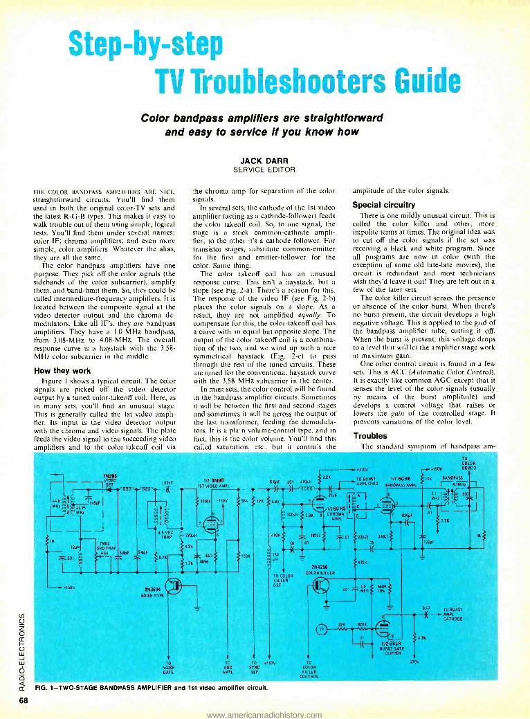
68
Step -by -step TV Troubleshooters Guide
Color bandpass amplifiers are straightforward and easy to service if you know how
THE COLOR BANDPASS AMPLIFIERS ARE NICE,
straightforward circuits. You'll find them used in both the original color -TV sets and the latest R -G -B types. This makes it easy to walk trouble out of them using simple, logical tests. You'll find them under several names; color IF; chroma amplifiers; and even more simple, color amplifiers. Whatever the alias, they are all the same.
The color bandpass amplifiers have one purpose. They pick off the color signals (the sidebands of the color subcarrier), amplify them, and band -limit them. So, they could be called intermediate- frequency amplifiers. It is located between the composite signal at the video detector output and the chroma de- modulators. Like all IF's, they are bandpass amplifiers. They have a I.0 -MHz bandpass, from 3.08 -MHz to 4.08 -MHz. The overall response curve is a haystack with the 3.58 - MHz color subcarrier in the middle.
How they work Figure 1 shows a typical circuit. The color
signals are picked off the video detector output by a tuned color -takeoff coil. Here, as in many sets, you'll find an unusual stage. This is generally called the 1st video ampli- fier. Its input is the video detector output with the chroma and video signals. The plate feeds the video signal to the succeeding video amplifiers and to the color -takeoff coil via
JACK DARR SERVICE EDITOR
the chroma amp for separation of the color signals.
In several sets, the cathode of the 1st video amplifier (acting as a cathode -follower) feeds the color takeoff coil. So, to one signal, the stage is a stock common -cathode ampli- fier; to the other it's a cathode follower. For transistor stages, substitute common -emitter for the first and emitter -follower for the color. Same thing.
The color takeoff coil has an unusual response curve. This isn't a haystack, but a slope (see Fig. 2 -a). There's a reason for this. The response of the video IF (see Fig. 2 -b) places the color signals on a slope. As a result, they are not amplified equally. To compensate for this, the color- takeoff coil has a curve with an equal but opposite slope. The output of the color- takeoff coil is a combina- tion of the two, and we wind up with a nice symmetrical haystack (Fig. 2 -c) to pass through the rest of the tuned circuits. These are tuned for the conventional haystack curve with the 3.58 MHz subcarrier in the center.
In most sets, the color control will be found in the bandpass amplifier circuits. Sometimes it will be between the first and second stages and sometimes it will be across the output of the last transformer, feeding the demodula- tors. It is a plain volume -control type, and in fact, this is the color volume. You'll find this called saturation, etc., but it controls the
amplitude of the color signals.
Special circuitry There is one mildly unusual circuit. This is
called the color killer and other, more impolite terms at times. The original idea was to cut off the color signals if the set was receiving a black and white program. Since all programs are now in color (with the exception of some old late -late movies), the circuit is redundant and most technicians wish they'd leave it out! They are left out in a few of the later sets.
The color killer circuit senses the presence or absence of the color burst. When there's no burst present, the circuit develops a high negative voltage. This is applied to the grid of the bandpass amplifier tube, cutting it off. When the burst is present, this voltage drops to a level that will let the amplifier stage work at maximum gain.
One other control circuit is found in a few sets. This is ACC (A utomatic Color Control). It is exactly like common AGC except that it senses the level of the color signals (usually by means of the burst amplitude) and develops a control voltage that raises or lowers the gain of the controlled stage. It prevents variations of the color level.
Troubles The standard symptom of bandpass am-
44.0
MHz
íN295 _Ivor 100PF
1'2 6MB8 1ST VIDEO AMPL
82K 6 8p .001 470pH
22022 *1500 56K I 2K 6.8K
270ÁH
12µN
001
*150V
43K
2K
3312
0056
2N3694 NOISE AMPL
TO
NO SE
GATE
TO
AGC AMPL
100K
39K
270V
TO BURST
1 AMPL GRID
27p
1.26GH8I1 °C 2
8 CHROMA AMPL L
470K 18032
01 01
po ISO pA
TO COLOR KILLER DET
t 1
TO +150V SYNC
SEP
2N4250 COLOR KILLER
TO CO OR KILLER
CONTROL
TO
COLOR
+í6áV" OEMOO
112 65148 10K BANOPASS
BANOPASSAMPL E-4.IMHz
MHZ I I
.01 22012 3301
.05
470K
3
820pF
001 5
EG 560K
3.1 f0 33 I
O7
u :
22K
120pf
IK
1/26818 BURST GATE
CLIPPER
047 TO BURST
I( -- AMPL CATHODE
4 7K
270V
FIG. 1- TWO -STAGE BANDPASS AMPLIFIER and 1st video amplifier circuit.
www.americanradiohistory.com
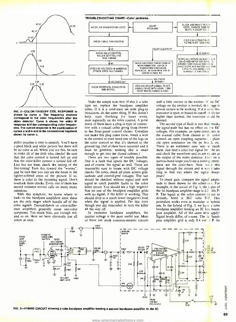
42.67
42.17
41.67
3.08
45 15
3.58
4.08
3.58 3.08 _ 4.08
FIG. 2- COLOR -TAKEOFF COIL RESPONSE Is shown by curve a. The frequency markers correspond to the color fregJencies after the video detector. Curve b shows the video IF response and the corresponding color frequen- cies. The overall response is the combination of curves a and b and is the conventional haystack shown by curve c.
plifier troubles is easy to identify. You'll have a good black and white picture but there will be no color at all. When you see this, be sure to make all of the little idiot checks! Be sure that the color control is turned full up and that the color -killer control is turned full off. Last but not least, check the setting of the fine -tuning! Turn this toward the "worms ", and be sure that you can see the beats in the lighter- colored areas of the picture. If so, there is color in the incoming signal. Don't overlook these checks. Every one of them has caused nuisance service calls on many many occasions.
With this symptom, we know where to look -in the bandpass amplifiers since these are the only stages which handle all of the color signals. Demodulators or color- differ- ence amplifiers generally cause one -color symptoms. Too much blue, not enough red, and so on. Here we have obviously lost all colors at once.
FROM ACCT KILLER PHASE
-OET
1 `
T.1 $ 3.3
iIj ME
1000\ 4.412
-NV1r- 2.2K
FROM 1ST,
VIDEO AMPL EMITTER 6JG5
1ST CHROMA BANDPASS AMPL
TROUBLESHOOTING CHART -Color problems.
NO COLOR: B &W PICTURE GOOD. F-
CHECK TUBES, TRANSISTORS
NO
CHECK COLOR CONTROL, KILLER CONTROL ANO
FINE TUNING
NO
CHECK DC VOLTAGES IN BANDPASS STAGES, ESPECIALLY BIASES.
VOLTAGES OFF
COLOR PROBLEMS
COLOR CLEARS UP
BLACK AND WHITE PIC1 OF GOOD: GHOSTS, RING NC
BEATS IN COLOR ON _Y
CHECK BANOPASS TRAN: FORMERS BY TOUCHING
CHECK BANDPASS TRANSFORMER WITH OHMMETER. CHECK IF TRANSFORMER HAS BEEN
REPLACED. BE SURE NEW ONE IS
CORRECT PART NO.
CHECK RESISTORS, CAPACITORS AND WIRING.
VOLTAGES NORMAL
FEED COLOR -BAR SIGNAL TO SET, SIGNAL -TRACE WITH SCOPE. FINO
POINT WHERE SIGNAL IS LOST.
NO CHA I
SCOPE ALL BYPASS CAPACI I S IN
BANDPASS AMPLIFIER CIF CL S. BRIDGE NEW ONES ACROSS UI .GI-
NALS. SCOPE AND BRIDGE E LE:TRO- LYTIC FILTER CAPACITOR! NEAREST TO THIS STASE.
Make the simple tests first. If this is a tube type set, replace the bandpass amplifier tubes. If it is a solid -state set with plug -in transistors, do the same thing. If this doesn't help, start checking for loose wires, most especially on the color control. A great many of these have a plug -in type of connec- tion with a coaxial cable going from chassis to the front -panel control cluster. Gremlins can make this plug come loose, break a wire to the control or even bend one of the lugs on the color control so that it's shorted to the ground lug. (All of these have occurred and it must be gremlins; nothing else is small enough to get into the closed cabinet.)
There are two types of trouble possible. One is a fault that upsets the DC voltages, and of course, the signal as well. These are reasonably easy to locate with DC voltage checks. On tubes, check all plate, screen grid, cathode and control -grid voltages. The last should be checked without signal and with signal to catch possible faults in the color killer circuit. You should see a high negative bias on one of the bandpass amplifier grids with no signal, if the killer is working. This should drop to a much lower (negative) level when the signal is applied. Do this even though you did remember to turn the killer all the way off.
In transistor bandpass amplifiers, the emitter voltage is the most useful test. Most of them use stock common -emitter circuits
42012
with a little resistor in the emitter. If he DC voltage on the emitter is normal, fit s tage is almost certain to be working. If it is zero, this transistor is open or biased to cutoff. I I it's far higher than normal, the transistor cc uld be shorted.
The second type of fault is one that breaks the signal -path but has no effect on the DC voltages. For example, an open condlctor in the coaxial cable from chassis to th color control, an open coupling capacito I plain old open conductor on the pc boa d, etc. There is an extremely easy way tc catch these. Just feed a color -bar signal into the set and check the waveform and its am3li.ude at the output of the video detector. Eve a on a narrow -band scope you'll see a comb F attern; these are the color -bars. Now, tra:e this signal through the circuit and it wort take long to find out where the signal disap- pears!
To check gain, compare the signal ampli- tude to those shown on the scherr.al c. For example, in the circuit of Fig. 1, the i iput of the 1st bandpass amplifier stage is 2.0 olts P- P. The signal at the color control (it put to demods, here) is 30.0 volts P -P This procedure works even in modular Tr hybrid sets. In the hybrid of Fig. 3, we ha e a tube bandpass amplifier feeding an IC 2nc band- pass amplifier. All of the same tests apply! Signal levels differ, of course. The Is band- pass amplifier grid is only 0.4 vol: l' -P. Its
1K
'2.2K
COLOR 470
KILLER PF
l 3
2ND CHROM BANDPASS AMPL
& COLOR DEMODULATOR
1K
T01
CO OR VII ED
OL PUTS
TO BURST AMPL GRID
250V
23 5V
FROM 3.56 MHz OSC OUTPUT
FIG. 3- HYBRID CIRCUIT showing a tube bandpass amplifier feeding a second bandpass amplifier In the IC.
dao ON TINT
69
www.americanradiohistory.com

CIEhas a terrific idea
for a few people vtho know what
they want.
www.americanradiohistory.com
If you want success in electronics ... if you want the skills pel:) ple are glad to pay for ... find out about CIE training.
It's a terrific idea that can get you on your way to success in electronics troubleshooting.
Let's face it, learning valuable new skills isn't something you just breeze through. Especially in a modern technological field like electronics troubleshooting. You've got to really want success if you're going to build your skills properly.
But, oh boy. the rewards when you do! In today's world, the ones who really know electronics troubleshooting find that people ... even industries... look for their help.
What about you? How much do you want the thrill of success ... of being in demand? Enough to roll up your sleeves and work for it?
Why it pays to build troubleshooting skills .
Suppose the automated production controls on an assembly line break down. Imagine how much money the manufacturer can lose when help doesn't come fast! And it takes a skilled electronics troubleshooter to move in ... locate the problem ... solve it ... and get the lines moving again.
Or take a TV station. Breakdowns are costly in broadcasting where time is money. Viewers won't sit forever waiting for sound or the picture to come back. Before they change channels, the station needs to get back on the air again -with the help of a skilled troubleshooter.
No question about it. Building new skills in electronics troubleshooting is an investment in your future. It's well worth the effort.
Why you should get CIE to help you do it .
Troubleshooting starts with ideas .. .
principles. CIE's Auto - Programmed Lessons help you get the idea -at your own most comfortable pace. Step by step at home, you explore each principle -each theory -until you understand it thoroughly and completely. Then you start to use it.
How CIE helps you turn ideas into reality .
If you're a beginner, you start with CIE's Experimental Electronics Laboratory. You actually perform over 200 experiments to help you grasp the basics. Plus you use a 3 -in -1 Precision Multimeter to get your first taste of the testing, checking, analyzing steps you take in troubleshooting!
How 3 practical steps help you build troubleshooting skills .
You'll take your first practical step in professional troubleshooting when you build your own 5 MHz triggered- sweep, solid -state oscilloscope.
As a trained troubleshooter, you'll use your oscilloscope the way a doctor uses his X -ray machine. As a student, you learn how to "read" waveform patterns on a big, 8cm. x 10cm. screen ... how to "lock them in" for closer study ... how to understand and interpret what they tell you.
Your second practical, skill -building step begins when you get your Zenith 19 -inch diagonal, solid -state color TV - featuring nine removable modules! Now's your chance to apply the new skills you learned with your oscilloscope!
With CIE's guidance, you perform actual service operations -the kind you'd handle on the job as a trained troubleshooter! Using the TV, you learn to trace signal How ... detect and locate malfunctions ... restore perfect operating standards ... just as you would with any sophisticated electronics equipment.
Finally, step three rounds out your experience as you work with a completely solid -state color bar generator - actually a TV signal transmitter that produces ten different display patterns on your TV screen!
You study a gated color bar rainbow ... crosshatch lines ... dot patterns.
You explore digital logic circuits .. observe the action of a crystal - controlled oscillator!
This practical, "hands on" trai ling takes concentration and effort. But it's enjoyable and rewarding. And t'., a great way to prepare for a troubleshooting career!
Why it's important to get your FCC License .
For some troubleshooting jobs. you must have your FCC License. Fer others, employers often consider t a mark in your favor. It's government - certified proof of specific knowlecge and skills!
Almost 4 out of 5 CIE graduates who take the exam get their Licenses. vlore than half of CIE's courses can prepare you for it ... and the broadest range of career opportunities!
Free catalog! Mail the card. if it's gone, cut ou and
mail the coupon. If you prefer to rite, mention the name of this magazinr. We'll send you a copy of CIE's FE EE school catalog -plus a complete package of independent home stuc y information! For your convenienc we'll try to have a representative call to help you with course selection. Mil the card or coupon ... or write: (1 1776 East 17th Street, Cleveland. Ohio 44114. r __.___... C I E Cleveland Instituus
of Electronics, inc.
1 1776 East 17th Street. Cleveland. Ohio 44'14
Accredited Member National Home Stud, Council
YES I want to succeed in electronics. Send nie my FREE CIE schoe I
Icatalog - including details about troubleshooting courses -plus my FREE package of home study information!
1 , 1 1 1 1 1 '
NAME (please print)
ADDRESS APT.
CITY
STATE ZIP
AGE PHONE (area code)
Check box for G. I. Bill information: Veteran Active Duty
Mail today! E 36
73
www.americanradiohistory.com
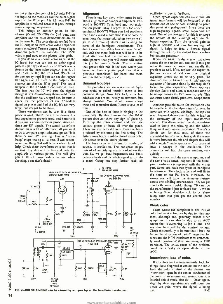
74
output at the color control is 3.5 volts P -P (at the input to the module) and the color -signal input to the IC at pin 3 is 1.2 volts P -P. Its amplitude is reduced because it goes through some coupling components.
This brings up another point. In this chassis (Zenith 25CC50) the 2nd bandpass amplifier and the color demodulators are all in the same IC. The color signals are fed from the IC outputs to three color video amplifiers (same as color- difference amps). These stages drive the picture tube cathodes. The B &W video signal goes to the picture tube grids.
If you do have a normal color signal at the IC input but you can see no color signal patterns (the typical rockers or lazy -S wave- forms) on the three color outputs (pins 9, 1I and 13 on the IC), the IC is bad. Watch out for one booby trap! If you can see flat- topped bar signals on all three of the outputs. the chances are that the IC is good! This could happen if the 3.58 -MHz oscillator is dead. The fact that the IC will pass the signals though it isn't demodulating them could mean that the oscillator has dropped out. Be sure to check for the presence of the 3.58 -MHz signal on pins 6 and 7 of the IC. It's not very large, but it's got to be there.
These waveforms can be seen if a direct probe is used. They'll be a little clearer if a low -capacitance probe is used, and better still if you use a crystal -detector probe. After all, these are RF signals. The actual waveform doesn't make a lot of difference: all you want to do is compare amplitudes and get an "Is it there or isn't it ?" reading. This is "bang - bang" scope- testing at its best. (I can recom- mend one thing that will be of a whole lot of help. Check these waveforms on a set that is working! Try different probes and note the amplitude at various points. This will give you a set of bogie values to use when checking a set that's dead.)
FROM COLOR KILLER
Alignment There is one key word which must be said
about alignment of bandpass amplifiers. This word is DON'T!! Caps, bold and two excla- mation points. May I repeat this for added emphasis? DON 'T! When you find problems that have caused a complete loss of color or even those that cause odd -colors (which we'll get to in a minute). don't start twisting the cores of the bandpass transformers! This didn't cause the sudden loss of colors. You'll only add one more fault that will have to be fixed after you find the real one. and the misalignment that you will cause will make this job far more difficult. (The exception that proves this rule is the case where you know. or have a pretty good idea. that a
previous "technician" has been into them with his liddle diddle stick!)
Unusual troubles The preceding section was covered faults
that could be called "stock "; more or less
common things. Now let's look at a few oddballs that are not nearly so common. but always possible. You should know about these and remember them. It can save a lot of time.
One of the best of these is ringing in the color only. By this I mean that the B &W picture does not show any sign of ghosting. Turn up the color control and you see
colored ghosts or beats all over the place. These are distinctly different from the beats produced by mistuning the fine -tuning. The latter shows beats in solid- colored areas only; this shows over the entire picture.
The basic cause of this kind of trouble, of course, is oscillation. The bandpass stages instead of amplifying are in violent oscilla- tion. So, we get beat -frequencies and beats between beats and the whole signal turns into a mess! Going one step farther back, all
FROM VIDEO CATH FOLLOWER & SYNC /CH ROMA AMPL
2.2 MEG
150K 68K
FROM 358 MHZ OSC GRID
TO B Y
R R Y AMPLS
ACC
T1
i3K
T 047
470K M 3.16MEG
315V
TO HORIZ BLANKING AMPL
1ST CHROMA BANDPASS AMPL
1/2 6GHBA
4.7
MEG %
.1
.001
47012 33K gK
.
260V
TO
K8Z DEMODS
15
300V
X
OPEN HERE
- COLOR
TAP 45052
39012 33052
KEYING PULSE FROM
F LYBACK
2ND CHROMA BANDPASS AMPL
0I 1.2 6GHBA 1
IBpF
820pF
FIG. 4 -COLOR RINGING can be caused by an
100K 1 8MEG
130V
open tap on the bandpass
.0I
IK 10°1 6.8K
260V
transformer.
oscillation is due to feedback. Open bypass capacitors can cause this. All
tuned transformers will be bypassed at the bottom end of one or both windings to place this point at signal -ground. Since these are high- frequency signals. small capacitors are used. One of the best tests for this is to scope the bottom of the windings right on the bypass capacitor. Turn the vertical gain as
high as possible and look for any sign of signal. It helps to feed a known signal through the set, like the output from a color - bar pattern generator.
If you see signal, bridge a good capacitor across the one under test and see if this gets rid of the unwanted signal, and usually the problem as well. If so. replace the capacitor. (In one somewhat odd case. the original capacitor turned out to be very good! To eliminate the problem I had to add another capacitor of the same size.) By the way, don't forget the filter capacitors. These too can develop faults and allow a feedback loop to be set up through the DC power supply. This can cause some dandy problems. Scope them too.
Another possible cause for oscillation can be trouble in the bandpass transformers. In some sets with tapped windings. the tap can open. Figure 4 shows one like this. A lead on the secondary of the input transformer opened. This disconnected the shunt resistor used to damp this winding and the whole thing went into violent oscillation. There's a simple test for this; most of these use unshielded transformers. Just grab the trans - formers between thumb and finger; this will add enough "hand- capacitance" to cause at least a change in the oscillation. The ohmmeter will find the open winding very quickly.
Another case with the same symptoms, and the same basic cause, happens if the band- pass transformer is replaced with the wrong part. Some sets have two types of bandpass transformers. They look alike and will fit in the holes on the PC board. However, the wrong one will leave the damping resistor across one winding disconnected! So, we get exactly the same trouble, though "It can't be the transformer! I just replaced that! ". When replacing these, double -check to be abso- lutely sure that you get the correct part number.
Weak color Cases where the complaint is not loss of
color but weak color. can be due to misalign- ment although this generally causes other symptoms. It can also be due to an ACC circuit that is overdoing its job a little. The key clue here will be the control voltage. Check this carefully to be sure that it isn't too far in the direction of cutoff: negative for tubes and the NPN transistors most common- ly used. positive if they are using a PNP transistor. The actual cause of the problem could be a leaky or open diode in the ACC.
Intermittent loss of color. If all colors are lost intermittently. look for
things like a plug /socket contact on the cable from the color control to the chassis. An intermittent open in the center conductor of the coax. or an intermittent ground due to a
frazzled shield could also do it. Once again, stage by stage signal- tracing will soon pin down the point where the signal is being lost. R -E
www.americanradiohistory.com
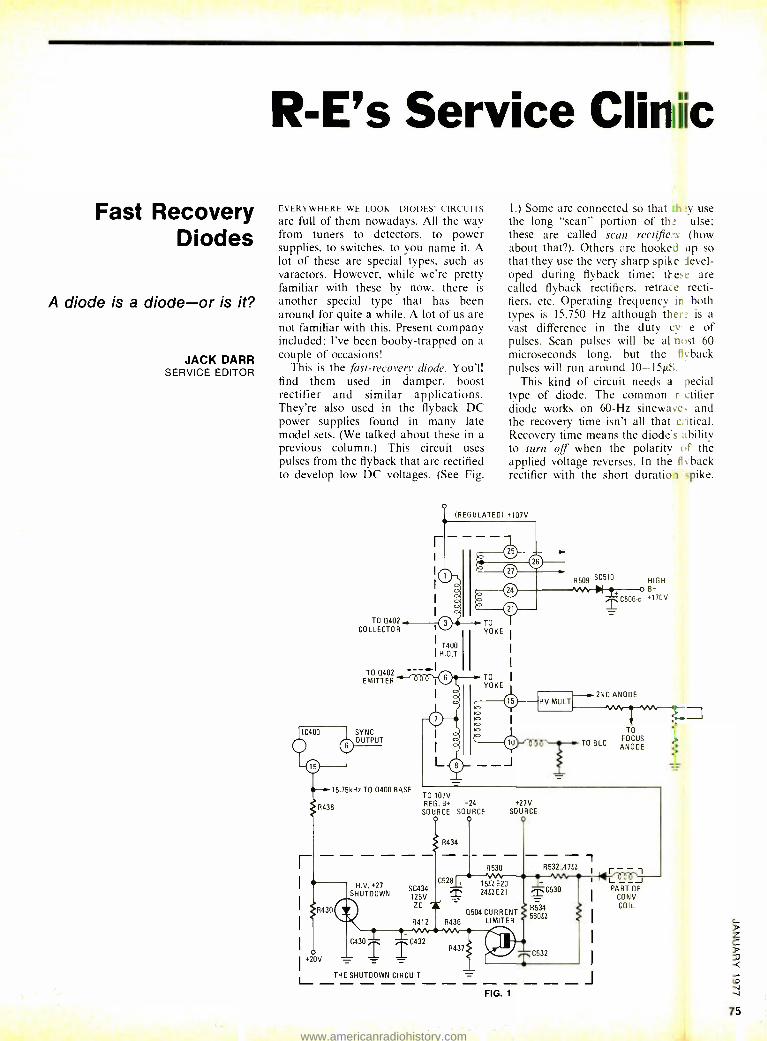
Fast Recovery Diodes
A diode is a diode -or is it?
JACK DARR SERVICE EDITOR
R -E's Service Cliriilic
EVERYWHERE WE LOOK -DIODES! CIRCUITS
are full of them nowadays. All the way from tuners to detectors, to power supplies, to switches, to you name it. A lot of these are special types, such as varactors. However, while we're pretty familiar with these by now, there is
another special type that has been around for quite a while. A lot of us are not familiar with this. Present company included; I've been booby- trapped on a couple of occasions!
This is the fast -recovery diode. You'll find them used in damper. boost rectifier and similar applications. They're also used in the flyback DC power supplies found in many late model sets. (We talked about these in a previous column.) This circuit uses pulses from the flyback that are rectified to develop low DC voltages. (See Fig.
TO 0402 COLLECTOR
1.) Some are connected so that th:y use the long "scan" portion of the pulse; these are called scan rectifie.ts (how about that ?). Others are hooked up so that they use the very sharp spike level - oped during flyback time; tl-ese are called flyback rectifiers. retrace recti- fiers, etc. Operating frequency in both types is 15,750 Hz although there is a vast difference in the duty cvcle of pulses. Scan pulses will be al east 60 microseconds long, but the flyback pulses will run around 10 -15µS.
This kind of circuit needs a special type of diode. The common rectifier diode works on 60 -Hz sinewave. and the recovery time isn't all that critical. Recovery time means the diodes ability to turn off when the polarity of the applied voltage reverses. In the fl yback rectifier with the short duration spike,
(REGULATED) +107V
R509 SC510
T400 I H.O.T.
TO Q402 I
EMITTER --r000
SYNC OUTPUT
TO YOKE
TO YOKE
HIGH 0+
2 0506 -c +170V
15.75kHz TO Q400 BASE TO 107V REG. B+ +24
SOURCE SOURCE
R434
R430
20V
H.V. +27
SHUTDOWN
C430
C528 SC434 125V zD
TO FOCUS
ANODE
+27V SOURCE
R530
+ 1552 E20 2452 E21
Q504 CURRENT R412 R436 LIMITER
C432
THE SHUTDOWN CIRCUIT
R437
FIG. 1
- - , R532,.4752
C530
R534 56052
C532 I
1
J
PART OF CONV COIL
75
www.americanradiohistory.com
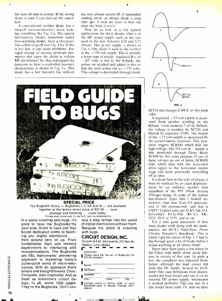
the turn -off time is critical. If the wrong diode is used it can foul up the opera- tion.
A conventional rectifier diode has a turn-off (reverse -recovery) curve look- ing something like Fig. 2 -a. The special fast -recovery diodes, sometimes called fast- switching diodes, have a character - istic called snap -off (see Fig. 2 -b). If this is too fast, it can cause problems. The rapid change of current develops har- monics that cause the diode to radiate RF interference! So, they redesigned the junctions to have a controlled recovery characteristic as shown in Fig. 2 -c. This diode has a fast recovery but without
the very abrupt switch -off. (I remember reading about an abrupt diode a long time ago: it took me Years to find out what the heck it was!)
Now let us look at a few typical applications for these diodes. One is in the DC power supply such as the one used in the new Sylvania E20 and E21 chassis. This power supply k shown in Fig. I. One diode is used as the rectifier in the + 170 -volt supply. This is actually a boost type of circuit- regulated B + of + 107 volts is fed to the flyback: the pulses are rectified and added to this so that the total comes out as + 170 volts. This voltage is developed through diode
SPECIAL PRICE The Bugbook library - Bugbooks I, Il, IIA and Ill - are available
together at the factory direct price of $37.00 ... save postage and handling ... order today.
Prices applicable only in the U.S. and its possessions.
In a world crawling with bugs, it's good to have the BugbooksTby your side. Good to have just four books dedicated solely to teach- ing you digital electronics . . .
from ground zero on up. From fundamental logic and memory experiments to interfacing with microprocessors. The Bugbooks are E &L Instruments' pioneering approach to mastering today's pulse -quick world of micro -elec- tronics. With an approach that's simple and straightforward. Clear. Complete. Well- illustrated. And as fresh as tomorrow's circuit de- sign. In all, some 1350 pages. They're the Bugbooks. Don't ven-
ture a step farther into the world of digital electronics without them. Because the place is crawling with bugs.
CIRCUIT DESIGN, INC. Division of E &L Instruments , PO Box 24, Shelton. Conn. 06484 r
Gentlemen: Please send me the set of Bugbooks for $37.00 postpaid. 1
I
I
I
Name
Company
Address
City State Zip
IEnclose check or money order or valid BankAmericard or Master Charge infor- mation.
\ NOT TOO ABRUPT
FIG. 2
SC5I0 that charges C506 -C to this peak value.
A regulated +27 -volt supply is devel- oped from another winding on the flyback. From terminal 7 of the flyback, the voltage is rectified by SC530 and filtered by capacitor C530. The output of the +27 -volt supply is monitored by the current -limiter transistor. This tran- sistor triggers SCR430 which kills the high -voltage. The 107 -volt B+ supply is also monitored through Zener diode SC434 for this same purpose. If any of these voltages go out of limits, SCR430 trips which then kills the horizontal drive signal to the horizontal output stage and turns practically everything off at once.
If a diode fails in this type of circuit. it must he replaced by an exact duplicate: never by an ordinary rectifier type regardless of the PIV (Peak Inverse Voltage) rating. In some of the typical fast -recovery types that I looked up, recovery time runs from 0.5 microsec- ond to 100 nanoseconds. and that is FAST! Typical units are G -E's GE -511, Sylvania's ECG -506, RCA's SK- 3515, 3517 or 3175. and so on.
For a very good discussion of how these diodes work along with the math- ematics, see RCA's Solid -State Power Circuits Designer's Handbook. This is where I got the curves of Fig. 1. I had to dig through quite a lot of books before I
found anything at all about them! There have been quite a few letters in
the Clinic mail lately about diode fail- ures in circuits of this type. In quite a few. the complaint was repeated diode failure although the load circuit fed from this DC supply showed no prob- lems! One irate technician even discon- nected the load circuit and ran it on an external DC power supply. whereupon it worked perfectly! This one was in a late model Sears color TV, and we helve
www.americanradiohistory.com
had quite a few cases involving the same model. I have been recommending replacement of this diode with a fast - recovery type. As we already stated, regardless of the peak inverse voltage rating or the current rating. a "slow diode" just won't work properly in this type of circuit. So; if you run into diode failure in sets using this kind of DC power supply, watch it! Be sure to use either an exact factory replacement part or a high -rated fast -recovery type from one of the better lines of replacement semiconductors. R -E
reader questions
POOR FOCUS I can't get a sharply focused raster on
this CTC -25X. The high voltage is 25 kV, B - is 405, boost normal, but I can get only 4200 -4300 -volts for the locus. The 4.7 megohm and 66- megohm resistors all check. The core of the locus transformer is all the way out and I still can't get locus. Any help appreciated. -G.S., Red Bank, NJ.
You're right; you're not going to get sharp focus with 25 -kV and only 4.3 -kV focus voltage. It takes about 20% of the
high voltage for sharp focus, or in this case, a bit over 5 kV. Since the focus circuit and high voltage are, driven by the same flyback pulse, everything else has to he OK! So, we've still got some- thing in this focus circuit.
Since the transformer shows a normal reaction, and your cathode current isn't high. it probably is not shorted. This leaves only one likely part; that voltage - dependent resistor shunted across the focus transformer. This is a 1.0 mA at 870 -volt type. Try an RCA 112876 or an Oneida GB -314. Try a new one. If it has gone down, it would load the focus transformer.
SAFE RATING OF RECTIFIER DIODES?
This Coronado TV6 -1614A came in with both rectifier diodes open. These are 200 - PIV units, in parallel. Could find no short or overload. Replaced with the same type. In two weeks it is back and they're open again! So, I put in a single 1.0A 600 PIV silicon. It's playing fine and seems to be holding up. What do you think ? -W.S., Bonaparte, IA.
In my opinion, you did the right thing! A 200 -PIV rectifier diode is just running a little too close to the bone on a 125- or 130 -volt AC line. I l.ke lots of safety factor, and you also seem to. Good idea. R -E
SENTURION - 12 Volts Pcw,rful Safe professional drivers require the ulti- mate in advance notice of fader traffic control zones - computer dEsi! ned an- tenna- integrated circuitry - and ble and visual warning - operates off yr ur car's electrical system. Send check, C O.D. or charge to my credit card as indic at fzi.
10 Day Money Back Guarantee RADATRON CORP. , \rr Exp. Dept. 2424 -49 P.O. Box 177 :]ar [e Blanche N. Tonawanda, N.Y. 14120 1),r ers Club
fAa ter Charge C.0 .D.
Charge my credit card acct. nc. Expir. Date
$89.95 each plus postage & tax whore : pplicable.
Signature
Name /Please Pr int
Address
Coy wore Zip ON --r
CIRCLE 2 ON FREE INFORMATK N CARD
®Bright LED readout
u AM-PM indicator
.1110 V operation
®Step -by -step instruction booklet
eaActito Alta -Reidy to /144e/We feat -R - EaCCCa,tGOftert
It's easy with the Calectro Digital Clock Kit! The com- plete kit with everything necessary for fast, easy assembly, including illustrat- ed step -by -step instructions. See the Digital Clock, TTL Power Supply, Motor Speed Control, DC Regulated Power Supply and Burglar Alarm kits at Calectro dealers everywhere!
L _41
GC ELECTRONICS DIVISION OF HYDROMETALS, INC. r RCKFORD, ILLINOIS 61101 U.S.A.
CIRCLE 71 ON FREE INFORMATION CARD
IWO "Ilk
77
www.americanradiohistory.com
LEARN QUICKLY- EASILY -AT HOME Only I.H.S.I. offers these unique correspondence courses MATHEMATICS ELECTRONICS
ENGINEERING MATHEMATICS ADVANCED MATHEMATICS
ADVANCED ENGINEERING MATHEMATICS
These unusual courses are the result of many years of research and teaching by the President of INDIANA HOME STUDY INSTITUTE, who has personally lectured in the classroom to thousands from all walks of life on mathematics, electrical and electronic engineering.
You must see these lessons to appreciate them! NOW you can master mathematics and electronics and ac- tually enjoy doing it! WE ARE THIS SURE: -you order your lessons on a money - back guarantee.
In plain language, if you aren't satisfied you don't pay a cent.
There are no strings attached.
WRITE TODAY for more information and your outline of courses. You have everything to gain and nothing to lose! LICENSED BY THE STATE BOARD OF INDEPENDENT POST- SECON- DARY VOCATIONAL, TECHNICAL, TRADE AND BUSINESS SCHOOLS.
THE INDIANA HOME STUDY INSTITUTE EASTERN DIVISION
P.O. BOX 1189 PANAMA CITY, FLA. 32401
CIRCLE 14 ON FREE INFORMATION CARD
Don't Get Caught With Your MODULES DOWN
Increase Your Profits By Utilizing Our Module Rebuilding Program
eeitoi4i these ¡eativreo! Original Parts. We use ONLY original parts. Brands we rebuild include Magnavox, Admiral, GE, Montgomery Ward, Quasar, RCA, Zenith and others. Quality. Only professionally trained tech- nicians will handle your modules. All modules are tested, temperature cycled, retested and airtested. Protective Packaging. Rebuilt modules are returned to you in polyethelene skin packag- ing for protection during shipping and storage. Fast Service. Quick, reliable service is our tradition. One Year Warranty. One year limited warranty on workmanship and parts.
N S PTS ELECTRONICS, INC. P.O. Box 272 Bloomington, IN 47401 812. 824.9331
OR, check the white pages for the location of the PTS branch nearest you.
CIRCLE 64 ON FREE INFORMATION CARD
R -E TESTS YAMAHA B -2 AMP continued from page 60
same scope photo. The accuracy of the repro- duced tone -burst speaks for itself.
Yamaha had made much of the fact that the V -FET circuitry used in both the B -1 and B -2 amplifiers results in the generation of fewer high -order harmonic -distortion compo- nents. While this may well be true at power output levels below rated power, our spec- trum analyzer's 75 -dB dynamic -range capa- bility precluded ékamining harmonic distor- tion-on a harmonic by harmonic basis. 75 -dB "down" is equivalent to only 0.0178% THD. and since, at less than rated power output levels the measured TI-ÌD (as a single number) was only 0.008% or thereabouts. we could not display harmonic distortion corn - ponents on the analyzer. At clipping. however. when distortion begins to reach more significant percentages. we were able to analyze the individual components that make up the distortion and, as can be seen in Fig. 8. higher -order distortion components be-
come just as significant as the usual second and third order components.
Use and listening tests Our overall comments concerning the
sound of the B -2 will be found together with our summary product analysis. in Table II. In using the amplifier for several days. we were particularly impressed by the action of the power meters which have an unusually rapid risetime (100 microseconds) and a slower (1
second) decay time. They therefore permit the user to really monitor close -to -true peak power of this (or any other externally connected) amplifier or of an externally used preamplifier and serve a function that we deemed more useful than that of the average - reading or conventional VU- meters found on some competitive products.
Despite the fact that the V -FET's require considerably higher quiescent (no signal) current than do conventional bipolar devices used in Class -B audio output circuits. there was little if any evidence of undue heat rise after hours of continued use of the amplifier for music listening purposes. Unless you are terribly concerned about the cost of the extra few watts consumed by this unusual ampli- fier. the extra current demanded by the V- FET circuitry should not pose a problem.
Obviously. an $850.00 basic power ampli- fier is not everyone's idea of how much they would like to spend for 100 watts -per- channel of pure audio amplification. But. in the case of the B -2, pure amplification is what you get -in every sense of the word. R -E
www.americanradiohistory.com
FREE bufglar-
alarm catalog over 900
systems, detectors, controls,
sounders, tools, locks,
supplies mountain west- .l=irtn.u,,lyc>
TO PROTECT HOMES, BUSINESSES, INDUSTRY
Huge selection of hard -to -find security equipment from stock. 64 fact -filled pages loaded with 100's of highest quality profes- sional alarm products, technical notes, diagrams -
ONE -STOP SUPERMARKET SELECTION INCLUDES:
ultrasonics, radar, infrared, undercarpet mats, magnetic contacts, smoke & heat de- tectors; Controls; Alarms: bells, sirens, phone dialers, lights, guard panels. Large selection of tools, relays, wire, holdup alarms, books. Fills need for industry, alarm cos., businesses, homes, institutions. Order your copy today. (Outside U.S., send $1.00.)
mountain west alarm 4215 n. 16th st. phoenix, az. 85016 (602) 263 -8831
CIRCLE 4 ON FREE INFORMATION CARD
KOMPUTER KORNER continued ¡rom page 25
SET switches, while the SNOOZE -ALARM DISPLAY switch is pressed. resets the alarm time to 12:00 AM.
If the alarm function is to be used. the PM output (pin 3) of the MM5385 must be used to activate an LED so that the alarm may be set for AM or PM. A current -limiting resistor (180 ohms for 10 mA) must be used in series with the LED.
Pressing the SNOOZE -ALARM DISPLAY switch also inhibits the alarm output for between 8
and 9 minutes after which the alarm is sounded and the alarm time is displayed.
When the alarm latch, S4. is closed, an output is available to drive an NPN tran- sistor. as shown in Fig. 1. This output is available for 59 minutes unless the SNOOZE -
ALARM DISPLAY switch is pressed, or unless the alarm is reset by the ALARM OFF switch. If it is desired to silence the alarm for a day or more, the ALARM OFF switch must remain closed. The alarm feature would be a valu- able addition to the auto digital clock in truck installations.
to be continued
H HIGH BLS PRESSURE
Treat it...and Ii. The Nations: Hi;h Blood Pressure Eduu' un Pragnm,
U.S. Department of !fulfil, Educet ?on, end MoBate.
o ools, its, io. nts,
ical es.
Over 24 years of service to the worli': finest craftsmen and technician,
A carefully selected and tested asst tment of unique, hard -to -find toots :lever gadgets, precision instruments, t nrgain kits. One -stop shopping for the to :!: ái*_ian, craftsman, hobbyist, lab spec ialit, production supervisor. Many flo's and measuring instruments ave(!able roc where else. One of the most unusual and :a nplete tool catalogs anywhere. Get your copy of the NC FLASHER today.
National Ca 2000 West Union Ave., Dep V Englewood, Colorado 80U
(303) 789 -1893 CIRCLE 10 ON FREF INFORMATICf, :ARD
You've seen the rest... now try the best.
Solderless strips, backing board and binding posts. Everything you need to build and test your own circuit. Used to be you'd get a circuit idea, lay out a pc board, print it, solder everything together, trouble- shoot, change your layout, try a new board, and spend abso- lutely too much time breadboarding. Now A P ACE All Circuit Evaluators let you breadboard in a fraction of the time. Make your changes im- mediately. Keep full leads on your components. Avoid the heat damage possible with repeated soldering and de- soldering. A P made the first modern solderless breadboard, and we still make them best.
Pick an ACE fc; Faster and Easier solderless circuit building and testing.
Send for cur complete A P c:( The Faster and Easier Book
Part No
ACE Model No
Tie Points
DIP Capacity
No Buses.
No Posts
Board Size (inches)
923333 200 -K (kit) 728 8 (16's) 2 2 4- 9/1845.9/16 923332 208(assem.) 872 8(16's) 8 2 4- 9/1645.9/18 923334 201 -K (kit) 1032 12 (14's) 2 2 4.9/1687 923331 212 (assem.) 1224 12 (14's) B 2 4. 9/16x7 923326 218 (assem. ) 1760 18 (14's) 10 2 6- 1/2x7.1/8 923325 227 (assem.) 2712 27 (14's) 28 4 889 -1/4 923320 236 (assem. ) 3648 36 (14's) 36 4 10- 114x9 -1/4
Order from your A P distributor today. Our
distributor list is growing daily. For the name of the
distributor nearest you call Toll -Free 800 -321 -9668.
log,
'rice Bach 18.95 28.95 24.95 34.95 46.95 59.95 79.95
A P PRODUCTS 4.ÿi INCORPORATED Box 110 -R Painesville, OH 44077
(216) 354 -2101 TWX:810- 425 -2250
CIRCLE 11 ON FREE INFORMATION CARD 7'3
www.americanradiohistory.com
Anybody who's into electronics certainly should be getting the everyday convenience and family security of automatic garage door operation ... especially now, with Perma Power's great Electro Lift ¡ - , - opener,.. made to fit in the trunk of your car, designed for easy handling and simple do- it- yourself installation. Available now at a surprisingly low price from your distributor.
P.S. Show off your opener to your friends and neighbors. You'll probably be able to pay for yours with what you make installing openers for them.
E PErma PowEr 0 tr
80
Chamberlain Manufacturing Corporation Perma Power Division 5740 North Tripp Avenue, Chicago, Illinois 60646 Telephone (312) 539 -7171
CIRCLE 52 ON FREE INFORMATION CARD
new products
More information on new products is available from the manufacturers of items identified by a Reader Service num- ber. Use the Free Information Card following page 88.
AUDIO INSULATORS. The model AT -605 is one method of combatting low -frequency acoustic feedback by isolating the phono pickup from vibrations such as rumbles from deep bass notes, passing buses and subways, and floor disturbances. The four height -adjustable chrome -finished insulators, selling for under
$25.00, help absorb disturbances before they reach the turntable. The audio insulator set fits under turntable or speaker corners, assuring optimum tone -arm tracking as well as protec- tion. The set includes a small bubble level, permitting accurate height adjustment neces- sary for maximum performance with today's lightweight pickup arms. -Audlo -Technica, 108 N. State St., Chicago, IL 60602.
CIRCLE 72 ON FREE INFORMATION CARD
INTRUSION ALARM, model A -18 uses existing public address, paging or background music speakers as sound pickups. Sounds of intrusion such as breaking glass, hammer blows, foot- steps, etc., cause the output relay to operate while normal building sounds such as heaters or
telephone rings are ignored. Sophisticated counting, audio -level and reset circuits reliably process potential threats. Audio detectors or speakers supplied cover as much as 2,500 feet each, depending on acoustics. Existing audio systems may be used with no additional wiring if
cables are shielded or twisted and run in
conduit. The A -18 can handle one to twenty audio inputs to provide protection for a small shop or up to a 30,000 -50,000 square -foot warehouse. -Mountain West Alarm Supply Co., 4215 North 16th St., Phoenix, AZ 85016.
CIRCLE 73 ON FREE INFORMATION CARD
STEREO TUNER, model KT -7300: features a
dual -gate MOS -FET in the RF stage and excep- tional stability even under the widest climatic changes of temperature and humidity. With FM sensitivity of 1.8 mV (10.3 dBf), the KT -7300 can handle signals as strong as 1 volt without over- load. Phase -linear ceramic filters in the IF stage bring selectivity to a high 80 dB.
A new FM decoder, consisting of a multiplier and a linear phase shifter, has a useful band- width of over 1 MHz. Signal -to -noise ratio is 68 dB (stereo), 73 dB (mono).
ff= 31112111111111111111111
C C+ 4k
A phaselock-loop circuit and individual LC filters for each channel provide 35 dB stereo separation 50 to 10,000 Hz with a solid 45 dB at the mid -range frequencies. Filters cut interfer- ence above 19 kHz, including the 19 -kHz carrier, without affecting the musical frequen- cies. Other features include a 25 -ms de- emphasis switch which gives perfect balance to Dolbyized FM broadcasts; two sets of outputs (one fixed, one adjustable), the first of which is
fed to TAPE for the highest signal desirable; the second is fed to the amplifier for tuner play when a lower level may be preferred; and lastly, terminals for an oscilloscope with which to check and correct multipath distortion, accurate signal strength and zero- center tuning meters, a
long, linear FM dial, as well as MPX filter and muting switches. -Kenwood, Dept. P, 15777 South Broadway, Gardena, CA 90248
CIRCLE 74 ON FREE INFORMATION CARD
IC DIGITAL COLOR -BAR PATTERN GENERA- TOR. model 388 is a new unit, housed in hand - sized cabinet, weighs 12 ounces and delivers accurate signals for test and alignment of any color or black- and -white television receiver. It
provides the following displays, projected on channels 2, 3 or 4: gated rainbow pattern for chrominance adjustment with ten standard color bars; single dot for static convergence adjustment; dot raster for final convergence, nonlinearity correction, pincushioning; single vertical line for horizontal centering; eight vertical lines for width and nonlinearity adjust-
www.americanradiohistory.com
ORP
10012
ments; single horizontal line for vertical center- ing; eight horizontal lines for height and nonlin- earity adjustment; single crossbar for centering and positioning; and crosshatch pattern for final convergence. pincushioning and nonlinearity correction.
Operates from two standard 9 -volt batteries or rechargeable nickel- cadmium cells. Also fea- tured, is an LED for power -on indication, crystal - controlled oscillator and timing circuits, for greater stability. $99.95. -EICO Electronic In- strument Co., 283 Malta St., Brooklyn, NY 11207.
CIRCLE 75 ON FREE INFORMATION CARD
STEREO AMPLIFIERS, models 300 and 300A. The model 300 is a 300 -watt stereo power amplifier kit designed for easy re- wiring into a 4- channel unit with a full complement of input and output functions. It is rated to deliver 150 watts per channel into 8 ohms, 20 Hz through 20 kHz, at less than 0.24% total harmonic distortion at rated power. Both channels are completely independent, with separate power supplies. Converted to quadriphonic operation. the am- plifier delivers 75 watts per channel into 8 ohms.
out of 2 Who ltave l it (fort know alar
-1I)4l rt4-
2t mni on Ane' ;Ca -s have high blood pressure But 52 percent of those who rave t don t know It
When blood pressure 'toes nigher than it shouid, and stays high I sets the stage for heart attack o' stroke
Most cases of high blood pressure can be controlled wrth drugs and other advances on treet.nent That's why you should see your doctor reg- ularly Only he can tell if you need help
A public satiric. ninososoo Irani your Heart Association
INSTRUMENTS IN Out -of- Circuit Transistor Analyze Dynamic In- Circuit Transistor & Radio ¡ Signal Generator Signal Tracer Volt Milliammeter
'i Battery Tester Diode Checker
Transistor Analyzer Mad, 1212 Factory Wired & Tested -$28.24 Easy -to- Assemble Kit -$19.21
YOU DON'T NEED A BENCH FULL OF EQUIPMENT TO TEST TRANSISTOR Rk u: S! All the facilities you need to check the transistors themselves - and the radio other cir- cuits in which they are used - have been ingeniously engineered into compact, 6-inch high case of the Model 212. It's the transistor radio troubleshoot' r th all the features found only in more expensive units. Find defective transistor',1 if circuit troubles speedily with a single, streamlined instrument Instead of it elaborate hook-up. ------'-------- - Features: EMC, 625 Broadway, New York 12, N.Y. Checks all transistor types - high or low power. Checks DC current gain (beta) to 200 in 3 ranges. Checks leakage. Link versal test socket accepts different base configurations. Identifies unknown tran- sistors as NPN or PNP.
Dynamic test for all transistors as signal amplifiers (oscillatnr check), in or out of circuit. Develops test signal for AF, IF, or RF Circuits. Signal traces all circuits. Checks condition of diodes. Measures battery or other transistor -circuit power- supply voltages on 12 -volt scale. No ex- ternal power source needed. Measures circuit drain or other DC currents to 80 milliamperes. Supplied with three ester - nal leads for in- circuit testing and a
pair of test leads for measuring voltage and current. Comes complete with Instruction manual and transistor listing.
Send me FREE catalog of the wmpiets value -packed EMC line, aid lams of local distributor.
NAME RE -1
ADDRESS
CITY TONE_ 3111TE
ELECTRONIC MEASUREME 625 Broadway, New York.
"FERRET" TV MINI -ANALYZER FOR FAST STEP -BY -STEP TROUBLE SHOOTING
SUB TUNER VHF AND UHF TUNER FOR RAPID TESTING OF ALL CHANNELS. CALIBRATED GAIN ADJUSTMENTS PROVIDE FOR SIGNAL STRENGTH COMPARISON.
DIGITAL GENERATOR CRYSTAL CONTROLLED FOR GENERATING STABLE PATTERNS WHEN CONVERGING RED, GREEN AND BLUE GUNS. IDEAL FOR LINEARITY, PIN CUSHION, CENTERING, FOCUS AND ALL PICTURE ADJUSTMENTS.
40 MHz OUTPUTS IF SIGNALS FROM DIGITAL GENERATOR AND SUB TUNER FOR STAGE -BY -STAGE ANALYZING AND TROUBLE SHOOTING. SG 7E5 $99.95
The VHF /UHF section of the Ferret allows direct substitution of the TV's tuner for fast, positive localizing of front end trouble.
The crystal controlled digital circuitry assures complete accuracy of both the vertical and horizontal frequencies. Accuracy is better than .005 %. Output from the generator may be coupled thru the tuner section or directly to the IF -video stages. Resolution is limited only by the picture quality of the TV receiver. Operates from 105 to 125 volts 50 -60Hz.
JQ/(QMa k 2849 FULTON STREET; BROOKLYN, NY 11207 PHONE: (212) 827 -15C0
GENERATOR SEC` I )N
CROSS -HATCH
LINEARITY ADJUSTMENT STANDARD FOR VERTICAL 41,11) HORIZONTAL POSITIONING, n c - URE CONTRAST. IF BANDWITH Ti ':T
DOT PATTERN
CONVERGENCE ADJU " :iT 'ENT STATIC AND DYNAMIC CON -
VERGENCE, BEAM ADJUST& E '5.
SOLD THRU DISTRIBUTORS O"ILY
Please send me more informatior.
Name
Address
Code
CIRCLE 34 ON FREE INFORMATION CARD 81
www.americanradiohistory.com
(4061#9616g6
OFFICIAL TESTING
LAB
the BEST oí ALL Ignition Systems.
s Officially Rated #as
ALLISON #1... RTES S stems
The ALLISON "Opt° LabotatorY Testing the Ignitron
by a Forerun Saving"
Ignitin o otio 1
the BEST "Fuel including
Sy h d Systems
Tested, including Systems ¡ ¡F Allison replaced the mechanical
Breaker -Points and Condenser with a "Highly Accurate" Optical Con- u 5
fro!. A Beam of Light. passing 8 Foreign
through a specially designed Parents Pending
-ROTOR" precisely triggers a Heavy -Duty "POWER MODULE" that BOTH "Charges and Fires" the Ignition Coil, with the "FASTEST" High Voltage RISE TIME, producing the MAXIMUM "HIGHEST ENERGY" SPARK available. * Since there is NO Mechanical Friction, there are NO Pans to ever WEAR or need replacing, and ONCE properly Timed, it
should NEVER need any Maintenance! DWELL never needs adjustment, it is PRE -SET to supply the OPTIMUM Perfor- mance at BOTH High and Low Speeds The RPM Capability of the "XR-700" is Factory Tested to 15,000 RPM
* The "High- Energy" SPARK INTENSITY and DURATION... permits the Positive FIRING of Spark -Plugs, even under the MOST ADVERSE conditions, results in more COMPLETE COMBUSTION and Eliminates "Engine Misfire ". hence fewér exhaust Emissions, IMPROVED Fuel Mileage, a
HIGHER Performance Level...and helps keep Plugs FROM FOULING, which greatly extends the Spark -Plug LIFE!
* Only the Highest Grade (U.S. Made) Solid -State Compo- nents are used ..UNAFFECTED by Moisture or Vibration! The Allison "XR -700" was engineered to OUTLAST the LIFE OF
YOUR CAR! * "EASY -TO- FOLLOW" INSTALLATION. (Not Necessary to Dismantle your Distributor. )
with the Exclusive... "Built -In" SOLID -STATE VOLTAGE REGULATOR
Itif The "XR -700" is a NEW, redesigned, EASIER TO INSTALL version of the
Allison Opto- Electric' with the New addition of the Voltage Regulator,
making it the MOST RELIABLE and Fool - Proof Ignition System ever invented.
"XR- 700 " ... Designed for those who want the BEST
in Performance, Gas Mileage, Quicker Starting, Eliminate frequent Tune -Ups and Maintenance Costs.
FACTORY- BACKED 10 -YEAR WARRANTY.
FREE Una Repai, o, RepiaCemem on ANY Defects
ORDER WITH CONFIDENCE... Remember, even if you PAY Three Times as much, you cannot get a better Ignition System than the "XR- 700 "!
At SAVE! ORDER FACTORY DIRECT. Send Check or M.O., Car Make, Year, No
Only $49.95 COMPLETE
(Calif. Res. add Taut That's EVERYTHING
INCLUDING... Postage & Insurance.
Cyl. (4, 6, or 8-Cyl )
w You may use your MASTER CHARGE or BANKAMERICARD. Send us (1) Your Number, (2) Interbank No., (3) Exp. Date * MC or BA Card Holders, ORDER by TOLL FREE PHONE:
(800) 423 -6525, Ext. 2 (When in Continental U.S.A.)
Before Buying ANY other Type Ignition System...
716- Send Postcard tor FREE BROCHURE. If you have already installed a Capacitive- Discharge Ignition
'CB" USERS: The XR -700 completely ELIMINATES the Major 441 Convert Your "C -D" Unit to BREAKERLESS!
Cause of Primary Ignition Noise) Interference. INCREASE ITS EFFICIENCY with "XR -CD "...Only $34.95
America's Oldest and Largest Manufacturer of Opto- Electronic Ignition Systems. © foN
ALLISON * Our BEST Salesmen... are the USERS of our ALLISON Systems!
AUTOMOTIVE CO. 1267 -E9, East EDNA PI., COVINA, CAL. 91722
CIRCLE 65 ON FREE INFORMATION CARD
PROFESSIONAL AIDS
SHELF FILES KEEP MAGAZINES,
CATALOGS, MANUALS,
JOURNALS, DIRECTORIES
AND REPORTS NEAT,
ORGANIZED
DESK TOP INSTANT DATA SYSTEM
FIND THOUSANDS
OF FACTS AT
COMPUTER SPEED
Eliminate the clutter of loose magazines, catalogs, etc. Find what you want, when you want it by utilizing these handy shelf or desk top files. Available in 6 sizes from Reader's Digest to newspaper size. Constructed of heavy duty fibreboard. Attractive blue oRSKNIZETOUK DESK
front panel. Adehesive identification labels included. Popular letter size: 111 /1x9x3a/ 10 for $15.80 25 for $28.97 Other sizes available Shipped pre -paid Request Catalog Canada, add $1.00
PROFESSIONAL AIDS CO. 1 S. WACKER DR., SUITE 177R CHICAGO, ILL. 60606
STONE ON SHELVES
NO FILING OR REFILING COMPACT. EVER! EASY-TO -DO
The modern rapid way to locate count- less facts at your desk without thumb- ing thru files. Specially coded cards are used to record any information you want close at hand - technical data, formulas, abstracts, case hist., bibli- ographies. Obtain just what you need in seconds -any group separates auto- matically simply by inserting a rod. No slow inefficient cross filing ... no me- chanical parts ... no special training ... minimum set up time.
30 DAY MONEY BACK GUARANTEE ONLY
Basic S3 900 package v (200 cards, hand notcher, sorting rods, instructions). Additional cards: 1000 for $57.00 postpaid. Sample Card Available Information Retrieval System, Div. of
PROFESSIONAL AIDS CO. 1 S. WACKER DR., SUITE 176R CHICAGO, ILL. 60606
POSTPAID
FREE LITERATURE
ON REQUEST
CIRCLE 54 ON FREE INFORMATION CARD CIRCLE 55 ON FREE INFORMATION CARD
For
faster service
USE
ZIP
CODE
on
all
All of the audio circuitry, except for the output stages, is contained on 2 factory-wired and pre- tested circuit boards. permitting complete assembly of the amplifier in about 10 hours. Amplifier and speaker protection is afforded by volt -amp limiting, 8 B + fuses, 4 speaker fuses, 2 thermal breakers, in addition to the AC line fuse. As supplied, the Stereo 300 is wired for maximum power output into 8- and 15 -ohm loads. Alternative conversion through simple internal changes enables even greater power outputs into lower impedance loads, with proper volt -amp protection. Behind the black panel, provision is made for either two or four rear - lighted output meters as optional accessories,
with a 4- position meter range switch. Walnut veneer end panels are supplied and rack mounting bracket will be available as an acces- sory. Measures 18t/u inches wide by 143/8 inches deep by 73/8 inches high. $489. The Stereo 300A comes already assembled. $699.99. -Dynaco Inc., Box 88, Blackwood, NJ 08012.
CIRCLE 76 ON FREE INFORMATION CARD
ANALOG MULTIMETER continued from page 48
sensitivity near I volt. Figure 5 -b shows the discrete differential
amplifier. Its advantage lies in its voltage gain. It also buffers the input attenuator from the low impedance of the meter movement. Once again the FET is used to obtain the high impedance. A modern integrated ver- sion of the differential amplifier is shown in Fig. 5 -c. An operational amplifier, buffered with FET followers on the inputs. is the amplifier.
The AC section of the TVM differs in a
few characteristics from the VTVM. The placement of the rectifier within the circuit is
the major difference between the two. The TVM rectifier is almost always placed after the ampliifier. which must then have both good AC and DC characteristics. The type of rectifier is also changed. Figure 6 shows the various types of rectifiers used in the AC portions of TVM's. Figure 6 -a is the simple input rectifier. much like that of the VTVM. This rectifier is peak responding. Its DC output must be divided by 1.414 to obtain the RMS value of a pure sinewave.
Figure 6 -b is a bridge rectifier driven from the outputs of a differential amplifier. This circuit is average responding -the output must be multiplied by 1.1 to obtain the RMS value. Figures 6 -c and 6 -d are other common implementations of the average responding circuit. Both of these employ the operational amplifier to overcome the nonlinear charac- teristics of the diode at low voltages. Figure 6 -c is a full wave. 6 -d a half -wave rectifier.
www.americanradiohistory.com
INTRODUCING
The NEW
GE KIT Phil Spector's original "Big Hurt"
sound is EXACTLY duplicated using PAIA's new constant time delay PHLANGER. This unit features a 1024 stage Charge Coupled Device analog shift register that exactly duplicates the effect of 2 tape recorders running out of synchronization.
Multiple user controls allow effects ranging from chorusing, voice doubling and reverb to full "Jet Plane" effects. Optional foot pedals provide hands free control of internal oscillator sweep speed or manual spectrum sweeping, #1500 PHLANGER Kit $59. 95
(plus shipping for 4 lbs. )
FREE CATALOG - ELECTRONICS DEPT. I- R
1020 W. WILSHIRE BLVD. OKLAHOMA CITY, OK 73116
CIRCLE 20 ON FREE INFORMATION CARD
EXECUTIVE DIGITAL ALARM CLOCK
KIT -ONLY $29.95
FAMOUS MAKE -LIMITED QUANTITY AVAILABLE ALL Parts Include°
FEATURES - Delux Ivory Case - 24 Hr. Alarm Set - Easy To Read 1/4" L 1: D'S - AM /PM Indication
DIGITAL ALARM
CLOCK KIT -$19.50
ALL PARTS INCLUDED FEATURES
24 Hr Alarm Setting AM /PM Indication Seconds
Display Snooze Alarm 12 or 24 Hour Display
50/60 Cycle Operation N.J. Residents Add 5% sales tae. Send check or Money Order to:
J.B. ELECTRONICS INC. P.O. BOX 321 SHORT HILLS, N.J. 07078
CIRCLE 58 ON FREE INFORMATION CARD
The AC and DC attenuators of the TVM are usually the same, unlike those of the VTVM. When the attenuator is common, it must be compensated to attenuate accurately at both high and low frequencies. Figure 7 is a compensated attenuator used in a 10- megohm TVM. The capacitors create a capa- citive divider with the same ratio as the resistors they shunt. If they were not used, the capacitive division ratio would depend en- tirely on the distributed capacitances of the resistors. These are substantial for high and negligible for low resistances. There is less than a decade attenuation across the first divider and a full decade across the last one.
INPUT
.033 Ì4.5MEG
4.5 MEG
.1V RANGE TG REUT a AMPL
FIG. 7 -THE INPUT ATTENUATOR of the Heathkit IM-1 04 as designed for AC operation. Capacitor shown in dotted lines represents stray resistances in the circuit.
The input to the attenuator is also AC coupled with a 0.033 -mF capacitor. It serves to keep DC from the attenuator and there- fore from the amplifier and rectifier, which respond to a combination of AC and DC. The total input capacitance of the TVM is somewhat greater than that óf the capaci- tance in shunt with the divider because of other distributed capacitances (see the dotted capacitor in Fig. 7).
FIG. 8- SWITCHABLE FILTER used to keep AC out of the amplifier when the instrument is used to measure DC voltages.
TVM's using a common AC and DC atten- uatór have a filter (Fig. 8). It is switched into the attenuator output during DC and during AC operation. The filter helps remove AC signals from the amplifier input when the meter is operating in the DC mode. Although the meter theoretically does not respond to AC signals, excessive AC can disturb the amplifier enough to cause error in DC read- ings.
to be continued
Test Equip. Special Discount Pr es.
E/CO
SENCORE
RCA 110" FLYBACK TRANS. For RIk. v ,95 N'ht. sets 18K1".. _........_ ..................... 110' TV DEFLECTION YOKE l'or all ty a s j 95 TV............................. ....................._ _
COMBINATION SPECIAL" RCA ' 11 95 FLYBACK & YOKE .............._....'........ E' 90 COLOR YOKE for red. la to 2° I95
1--1 70 COLOR YOKE for round colt r K 95
CIOTs UHF TUNERS Transistor type used it .rit ßg5
T5 ,etc . I 111 GE UHF TUNERS Transistor Type M. I ^ 95
ADMIRAL TUNER Model P4('., . 5
(Series) .._..
ADMIRAL TUNER Model T941 I 5
(Transistor). .
GE TV TUNER Model 5
(Series).. ....... PHILCO UHF /VHF TUNER
type..................... .. ............ ZENITH TUNER Model 175 -116 t ..r _ 7. - L 95
I15 1.......................... ......._....._ _. . BLUE LATERAL MAGNET ASSY Repl. fir
1
79 most TV
COLOR DELAY LINE 1 69 Used in mast TV _ .. .............. ...... ......._
ZENITH SILICON STICK RECTIFIER Pair_ p95 =103-915 ..................... .........._ . ZENITH TRIPLER Part .212- 109 -Szmv 95 as ECG501 . n 3- POLARIZED CHEATER CORDS
COLOR R POWER TRANSFORMER CA Pats 95 .2úR150 I 2- COLORBURST CRYSTALS ing (3579.545 K C 1 ...................... _.
3 -COLOR TV RECTIFIER 95 ti500KV ................ .__......__......__......__. 6 -TV ALIGNMENT KIT na,, populi r aqg
.........._...... 4 -TV ALIGNMENT KIT to useful 5 -DUAL DIODE
asst ................. ............................... most popular t e 50
(Common or Series) VU 'T' PANEL METER 129
0 _O dh Scale ..........._.........._. COAX CABLE RG59U (Bk.) e' - ^ : ar..._ ......... ......................_....._.. L69
H VOLTAGE POWER TRANSISTOR r. ... g
to Hep 707 ........ ............................_.. TRANSISTOR RADIO asst. types le- . - 0
bad, broken. as -is TAPE RECORDERS asst. types (good, tea.:, 400 broken, as -isI 100' GREY SPEAKER e00
LiWIRE ._......._........._... ._ ............._..........._ L UNIVERSAL TV ANTENNA back of set t. :g
(5 section)....... ...._.........._ ............... 3- ZENITH VIDEO AMPURER Part = O
743 ..................................................... WAHL CORDLESS SOLDER IRON i 5
(complete with charger) ___ .._....
B" HEAVY DUTY 100Z. SPEAKER 0
typeS ohm ....... ............................... 6"i9" HEAVY DUTY 100Z SPEAKER Type 8 Ohm ...... .. ........ . ..... .......... .._
ESTEREO HEADPHONES Hl FI Quality 95 withplug .......... .... ...... "
TACHOMETER 2 4" SQUARE PANEL MET e0 ER 1 -VDC- 0-5000 RPM L
"1-1 CASSETT 2(
E
s
TYPE MIKE Universal Pltg . 99 Mí Ohm
5 ZENIER DIODES 1HO 154757A -1 W -50 V
4 -ASSTD PHILCO PUSH PUSH TYPE S9
SWITCHES 2 2 -HEP 50015 SILICON TRANSISTORS ............... " 1
1-NEP 55004 SILICON NPN TRANSISTOR. 100
1 -HEP S5011 OR NEP 55012 HV
TRANSISTORS I 1--1 TRANSISTOR SPECIALS SK3006, SK3on+, 0D
SK3020 N. TRANSISTOR SPECIALS 00 SK:3122, SK3124 N. TRANSISTOR SPECIALS SK3009, SK302, gig El TRANSISTOR
1N, BE IC3 OR IC4 INTERGRATED
CIRCUIT I 6- SILICON RECTIRERS 1 Amp -100 Do
PI J
1 TUBE AM FM STEREO AMPLIFIED 95
CHASSIS complete with tubes as is ._ 9 DELUXE PILLOW SPEAIIER with plug t5 249 volume control
2 -12BH A RCA
TUBES
R16- MI.3V- NI 150M
PILOT a)
BULBS (G.3V -30Ma) er 00
3 ":5" SPEAKER 3g TV replacement J.
1_1 1- ELECTROLYTIC COND. 1 0 300MFD -250V 3- ELECTROLYTIC COND. 100í80.2r O r-1 MM -300V
3 PACK C-60 CASSETTE fine quality
0
......... ..._ ................__......._. _..
Minimum Order $5.00 Immediate Delly 'y
BROOKS RADIO & TV CORP. 529 Columbus Ave., New York, N.í..0024
TELEPHONE 212.874 5600
00
00
CIRCLE 59 ON FREE INFORMATICr4'7ARD 83
www.americanradiohistory.com
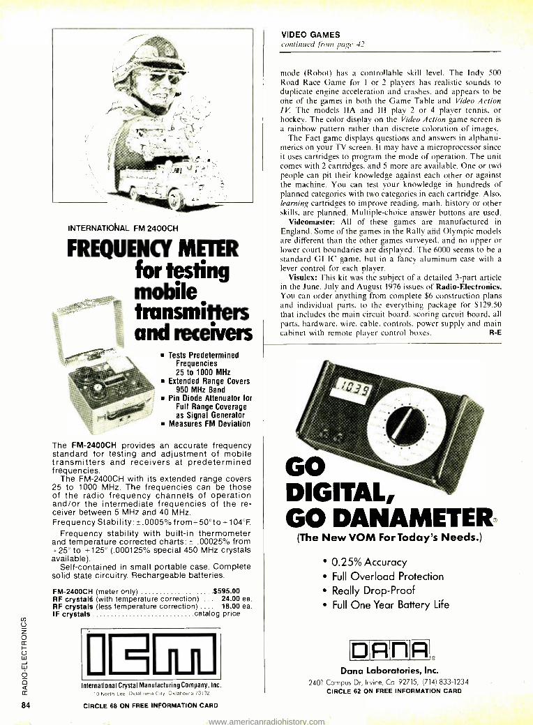
INTERNATIONAL FM 2400CH
FREQUENCY METER for testing mobile transmitters and receivers
Tests Predetermined Frequencies 25 to 1000 MHz
Extended Range Covers 950 MHz Band
Pin Diode Attenuator for Full Range Coverage as Signal Generator
Measures FM Deviation
The FM- 2400CH provides an accurate frequency standard for testing and adjustment of mobile transmitters and receivers at predetermined frequencies.
The FM- 2400CH with its extended range covers 25 to 1000 MHz. The frequencies can be those of the radio frequency channels of operation and /or the intermediate frequencies of the re- ceiver between 5 MHz and 40 MHz. Frequency Stability: ±.0005 %from +50 °to +104 °F.
Frequency stability with built -in thermometer and temperature corrected charts: ± .00025% frdm +25° to +125° (.000125% special 450 MHz crystals available).
Self- contained in small portable case. Complete solid state circuitry. Rechargeable batteries.
FM- 2400CH (meter only) $595.00 RF crystals (with temperature correction) .. 24.00 ea. RF crystals (less temperature correction) . 18.00 ea. IF crystals catalog price
International Crystal Manufacturing Company, Inc
10 North Lee Oklahoma Cty Oklahoma 73102
CIRCLE 68 ON FREE INFORMATION CARD
VIDEO GAMES continued /irons page 42
mode (Robot) has a controllable skill level. The Indy 500 Road Race Game for 1 or 2 players has realistic sounds to duplicate engine acceleration and crashes, and appears to be ohe of the games in both the Game Table and Video Action IV. The models IIA and III play 2 or 4 player tennis. or hockey. The color display on the Video Action game screen is
a rainbow pattern rather than discrete coloration of images. The Fact game displays questions and answers in alphanti-
merics on your TV screen. It may have a microprocessor since it uses cartridges to program the mode of operation. The unit comes with 2 cartridges, and 5 more are available. One or two people can pit their knowledge against each other or against the machine. You can test your knowledge in hundreds of planned categories with two categories in each cartridge. Also, learning cartridges to improve reading. math, history or other skills. are planned. Multiple- choice answèr buttons are used.
Videomaster: All of these games are manufactured in England. Some of the games in the Rally and Olympic models are different than the other games surveyed. and no upper or lower court boundaries are displayed. The 6000 seems to be a
standard GI IC game, but in a fancy aluminum case with a
lever control for each player. Visulex: This kit was the subject of a detailed 3 -part article
in the June. July and August 1976 issues of Radio- Electronics. You can order anything from complete $6 construction plans and individual parts, to the everything package for $129.50 that includes the main circuit board, scoring circuit board, all parts, hardware, wire, cable, controls, power supply and main cabinet with remote player control boxes. R -E
Go DIGITAL, GO DANAMETER®
(The New VOM For Today's Needs.)
0.25% Accuracy
Full Overload Protection
Really Drop -Proof Full One Year Battery Life
D A n A Dana Laboratories, Inc.
2401 Campus Dr, Irvine, Ca 92715, (714) 833 -1234 CIRCLE 62 ON FREE INFORMATION CARD
www.americanradiohistory.com
next month FEBRUARY 1977
Preview of 40- channel CB gear
How manufacturers plan to handle trade -ins or conversions on 23 -chan- nel gear
How to tune 40 chan- nels. Rotary, Keyboard, Thumbwheel
I Directory of manufac- turers
Antennas for 40 chan- nels. Can present anten- nas be used?
New FCC regulations
clitM7aoNd'
Thy ER DEGREA,
Y1ANi A/q O[6¡S PF
oe FMf1oc ANO OA1yG,
Mwrf `UK['Mr"..
mue w'° ^OO p , .° c . H, ...
tA(Nry
ty IONOr-cuMMws
" ,,,e 5 f ? sown
N wit. aM..mao FET WT.?t01.J
mw...s1r. ACH VE
INGREDIENTS
WARMER SPRAY FOR MORE CLEANING POWER
TUN -O -WASH has long been the Intl 3s- try standard in tuner degreasers. Ncw, it's better and more economical than ever.
No, we haven't tampered with the fam- ous TUN -O -WASH formula. That's bo good to change. What we have changed is the propellant. We now use carbon dioxide (CO:) as a propellant. This per- mits us to fill the can with 97% act ve ingredients, compared with only 65% ac- tive ingredients before this development. The can is the same size, but you get more cleaning power for your money
There are other advantages to us ng CO2 as a propellant. FIRST, the spray comes out 100 warmer. Everyone knows that heat increases solvent action. SEC- OND, the particles of solvent come oul in larger drops, making for a wetter spray. And, finally, CO2 enables us to maintaie a uniform 70 pound pressure until the on is completely empty.
This is another first from lie elec- tronics industry's leading chemical mEn- ulacturer.
p_cHEMrnowICs INCOOOOGATVo INCORPORATED
35 HOFF MAN AYE . HAUPPAUGE. N Y 11181 15161 582 -33.2
CIRCLE 26 ON FREE INFORMATION CARD
Put Professional Knowledge cur -::I a
COLLEGE DEGFIEE in your Electronics Career thrc. gh
by correspondence, while continuing yoi.0 pres- ent job. No commuting to class. Study a your own pace. Learn from complete and e u plicit lesson materials, with additional assistance: from our home study instructors. Advance as last as you wish, but take all the time you need to ITnaster each topic. Profit from, and enjoy, the advatitages of independent study.
The Grantham correspondence degree çrogram in electronics is comprehensive. It begin with basics, written in very simple language , and continues through the B. S. E. E. degree level. Throughout the entire program, heavy empha- sis is placed on clear explanations written ir great detail, progressing from the simple to the com- plex, in easy steps.
Our free bulletin gives complete details on the curriculum, the degrees awarded, the re'uire- ments for each degree, and how to enroll.
GRANTHAM SCHOOL OF ENGINEE :FING 2000 Stoner Ave., Los Angeles CA 911025
Telephone (213) 477 -1901
Worldwide Career Training thru Home Study Mail the coupon below for free bulletin
r Grantham School of Engineering 11E 1 -" 2000 Stoner Ave., Los Angeles, CA 90C25
I have been in electronics for years. ? 1 .se mail me your free bulletin which gives details c 1n- cerning your electronics degree programs.
Name Age
Address
City State Zip
CIRCLE 9 ON FREE INFORMATION CARD
www.americanradiohistory.com
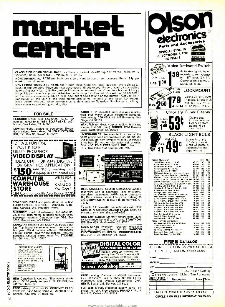
market center CLASSIFIED COMMERCIAL RATE (for firms or individuals offering commercial products or services). $1.40 per word ... minimum 15 words. NONCOMMERCIAL RATE (for individuals who want to buy or sell personal items) 85¢ per word ... no minimum. ONLY FIRST WORD AND NAME set in bold caps. Additional bold face (not available as all caps) at 100 per word. Payment must accompany all ads except those placed by accredited advertising agencies. 10% discount on 12 consecutive insertions, if paid in advance. All copy subject to publisher's approval. Advertisements using P.O. Box address will not be accepted until advertiser supplies publisher with permanent address and phone number. Copy to be in our hands on the 26th of the third month preceding the date of the issue (i.e. August issue closes May 26). When normal closing date falls on Saturday, Sunday or a holiday, issue closes on preceding working day.
FOR SALE RECONDITIONED test equipment. $0.50 for catalog. WALTER'S TEST EQUIPMENT, 2697 Nickel, San Pablo, CA 94806
LOW cost digital /analog test equipment. Excep- tional values. Free catalog. SALEN ELECTRON- ICS, P.O. Box 82, Skokie, IL 60076
'12" ALL PURPOSE 1 VOLT P TO P
GREEN PHOSPHOR
VIDEO DISPLAY IDEAL UNIT FOR ANY DIGITAL OR GRAPHICS APPLICATION
95OAdd $10 for packing and shipping in continental US
COMPUTER WRITE FOR
WAREHOUSE CATALOG
STORE Cio Dept.R
584 Commonwealth Ave. Boston 02215a
86
SEMICONDUCTOR and parts literature, J. & J. ELECTRONICS, Box 1437R, Winnipeg, Mani- toba, Canada. U.S. Inquiries Invited.
SURPRISE! Build inexpensively, the most un- usual test instruments, futuristic gadgets using numerical readouts! Catalogue free! GBS, Box 100B, Greenbank, WV 24944
CANADIAN discount and factory clearouts cata- log. Top brand stereo equipment, calculators, test gear, CB & communications, telephones. Factory dumps- government surplus. Amazing bargains. Unusual items. Rush $1. ETCO -RE, 521 5th Ave., NYC, 10017
PICTURE TUBE MACHINE We her ana .sett NEW and USEZ, CRT rebuilding n chine,. COMPLETETI tN. NI:. Buy with CONFIDENCE
n the ORIGINAL AR,It. For complete details send name address, zip code to LAKESIDE INDUSTRIES 3520 W Fullerton Ave Cnlcego. III. 60647 Phenw. 312.397 -3395
i
NEW Canadian Magazine, "Electronics Work- shop", $5.00 yearly, sample $1.00. ETHCO, Box 741 "A ", Montreal
FREE catalog. IC's, Semi's. CORONET ELEC- TRONICS, 649A Notre Dame W., Montreal, Que. Canada, H3C -1H8. US Inquiries.
RADIO & TV tubes 366 each. One year guaran- teed. Plus many unusual electronic bargains. Free catalog. CORNELL, 4217 -E University, San Diego, CA 92105
MANUALS for Govt. surplus radios, test sets, scopes, List 506 (coin). BOOKS, 7218 Roanne Drive, Washington, DC 20021
UNSCRAMBLES: We manufacture one of the finest police code unscramblers on the market. Our prices are very competitive and our service is the best. For further information call or write: DON NOBLES ELECTRONICS, INC., Dept. RE, Rt. 7, Box 265B, Hot Springs, AR 71901
e. © EC -101 CURVE TRACER
STILL BY FAR THE LOWEST COST FULL FUNCTION
CURVE TRACER ON THE MARKET. ATTACHES TO
YOUR SCOPE IN SECONDS. USED BY EDUCATORS,
PROFESSIONALS AND HOBBYISTS ALL OVER THE
WORLD. 30 DAY MONETRACR GUARANTEE.
lab sciee nce
STILL ONLY
$39.50 ADD S2PLH
COLO. RES.
SALESTAx
PO BOA 1972, BOULDER, COLO. 50306
DESCRAMBLERS: Several professional models that work with all scanners. Tone encoders/ decoders. Scanmate, AAPP, radar detectors, Big Ears, alarms, books, kits, parts. Catalog 25 cents: KRYSTAL KITS, Box 445, Bentonville, AR 72712
TV picture tubes -ASE manufactures over 2200 types, B/W and color. ALLIED SALES, Dept. 43, Pimento, IN 47886. (812) 495-6555.
NON semi surplus. Monthly picture flyer. Qual- ity. Low price. Send 25C. U.S. only. STARTRON- ICS, Box 683, McMinnville, OR 97128
SOLID -STATE television recorder electronic unit with documentation. $21.45. MADISON ELECTRONICS COMPANY, INCORPORATED, Box 369, D102, Madison, AL 35758
DIGITAL COLOR
Kit or Wired
CONVERGENCE GENERATOR Uses latest CMOS -LSI technology. For
servicing Color TV, etc. Selects up to 16
patterns. As low as $39.95 (kit). Plans
$5.00. RF & Video output. 2 Yr. Warranty.
SEND FOR DATA NOW
SCIENCE wonkshop BOX 393
BETHPAGE, N.Y. 11714
FREE catalog. Calculators, digital thermome- ters, ultrasonics, kits, strobes, NiCads, LED's, transistors, IC's. Unique components. CHA- NEY'S, Box 27038, Denver, CO 80227
FOR real: Military- industrial quality parts, low prices, no junk. Free catalog. BRAND X, Rt. 3, Box 223, Ontario, OR 97914
0160111) /Ilectron parts and Access SPECIALIZING
IN
ELEC ONICS YEARS
FOR
içs ones
I ma9leL. oas jm,M
BA NNAMEAICAAO
,Kr. Ma
oice Activated Switch ße1, -® Activates lights, tape
59 recorders, etc. Comes X M -566 with 5" leads. 3 x 1".
Reg. 1
98 Operates on 4.5 VDC. Shpg. wt. '/a lb.
Under LOCKMOUNT ash
Locks place.
or player in place, Slides in &
1 7 9 Reg'
250 out. 6 x' /4 x 7 ". 6 AU -344 or 12 VDC. 2 lbs.
Color TV Tuner Cleaner
01 TL-459 Cleans and lubricates con- trol & contact
49 points. 6 oz 4 CI can. '/2 lb.
BLACK LIGHT BULB XM -291 Screw into any
ordinary k P eg. Light up posterssocet. ,
decorations, etc. ' Shpg: wt.'/ lb.
PORTS L COMPONENTS REG. SALE
'iI RPM Timing Motor. 117 V. AC MO -277 49 .30 1 RPM Timing Motor, 117 V. AC MO -289 .99 .30
8 RPM Reversible Motor, 117 V. AC MO -393 2.50 .99 Tubular Capacitor Rd. 100 Pcs. CC -229 2.00 1.29
Ceramic Capacitor Kit, 100 Pcs. CC -211 1.49 1.19
100 Ceramic Capacitors, values clearly marled CC -210 1.29 .80 50 Asst. Electrolytic Capacitors. Asia) /Radial CO -407 5.00 2.00 loo Asstd. Carbon Resistors. 1 -1/4-1 Wan Sizes RR -077 1.79 1.00
5 Asstd. SCR's, 15 V. and Up. 100 MA to 1.6 AMP TR -298 1.79 1.00
500 MW Zeno, Diodes. 4.3- 6.3- 9.1 -12 L 15 Volts DI -052 1.00 50
3 Unijunction Transistors. 40 V. 375 MW. 4 ON/S TR -441 1.29 50
L.E.D. Pkg. of 5 Red, 2 Volt - 5 MA PL -233 1.19 .60
Ultra -Mini LLD. Pkg. of 5 Red. 2 V. 5 MA PL -289 1.29 .70
TI Calculator He Board, 20 Keys XM 523 5.00 1 -60
31/2 Digit liquid Crystal Display XM -371 10.00 3.00 Darlington Amp. Transistor Kit, 6 Transistors TR -507 2.00 1.50
Photo Transistor, 5 Pieces Epoxy Type TR -502 1.00 .60
6 Amp. Full Wave Bridge Rectifier 50 PIV DI -057 1.20 80
6 Amp. Full Wave Bridge Rectifier 400 PIV 01 -056 1.90 1.00
PNP Transistor Assortment Pbg. of 10 TR -445 1.00 60
MPH Transistor Assortment Pkg. of 10 TR -446 1.00 60
7- Segment L.E.D. Display .3 In. Green XM -341 2.69 1.00
7- Segment L.E.D. Display .3 In. Red XM -370 2.00 1.00
7- Segment L.E.D. Display 3 In. Yellow XM -342 2.49 1.00
Micro Type Switch Kit, 7 Assorted SW-430 1.89 1.49
Knob Kit, 25 Pas. Assorted IN-030 1.00 69 Robby Motor Kit, 3 -6 V. DC. Plg, 5 M0 -333 .59 49
TOOLS - SPECIAL AND PRACTICAL
Wee Wrap Tool, 30 Oa Wire on .025 Past TL -845 2.60 2.00
IC Insertion/Extraction Tool T1 -846 1.25 1.00
IC Plug-in Test Adapter TE -396 2.60 2.00 12 Volt DC Soldering Iron, Pencil Tip TL-793 4.00 3.00 Dymo label Maker. Uses 45 In. Tape 11452 1.19 90 Double Face Foam Tape ik o 52 In. TA -903 1.00 80
FREE CATALOG Ills R(1N Pl F(:TRfNICS 25(1 S F(1R(-IF ST1
DEPT LT, AKRON, OHIO 44327
NAME
ADDRESS
CITY STATE
ZIP Send Olson Catalog Free PA Catalog Ship The Following:
la: Num er Description
lPrice ENCLOSE POSTAGE AND SALES TAX_ J CIRCLE 1 ON FREE INFORMATION CARD
www.americanradiohistory.com
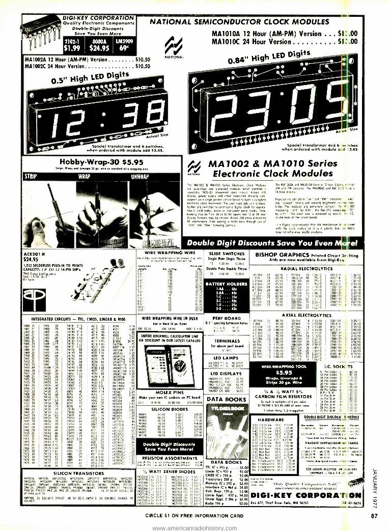
DIGI -KEY CORPORATION Quality Electronic Components
Double -Digit Discounts Save Mou Even More
2102 -1 8080A
$1.99 $24.95 LM3909
69`
NATIONAL SEMICONDUCTOR CLOCK MODULES
MA1010A 12 Hour (AM -PM) Version $1:.00 MA1010C 24 Hour Version $1:.00
Q.S4'E High LED Digits MA1002A 12 Hour (AM -PM) Version $10.50 MA1002C 24 Hour Version $10.50
0e51í High LED Digits
NATIONAL
Actual Size
Special transformer and 6 switches, when ordered with module add $3.45.
Hobby -Wrap -30 55.95 5h1ps, Caps and Ulrwrepr 30 ga. wire en ssendard aire wrapping pins
ACE201 -K
$24.95 1,032 SOLDERLESS PLUG -IN TIE POINTS CAPACITY: L l' TO 12 14 -PIN DIP', TWO Swot' bng Size: 49/16"
indi by r-
posts
Kit form
JJ
Special transformer and 6 w tches when ordered with module nn d i3.45
44 MA 1002 & MA 1010 Series NAnatoar Electronic Clock Modules
The MA1002 B MA1010 Series Electronic Clock Modules ore assembled and pretested modules which combine a
monolithic MOS-1.51 integrated clock circuit, 4 -digit LED
display, power supply and other associated discrete com- ponents on a single printed circuit board to form a complete electronic clock movement. The user need add only a trans- former and switches to construct a digital clock for applka- tlon in clock -radios, alarm or instrument panel clocks. Time- keeping may be from 50 or 60 Hz inputs and 12 or 24 hour display formats may be chosen. Direct LED drive eliminates Rf interference. Time setting is mode easy through use of -Fost" and "Slow" scanning controls.
The MA1002A and 1061010A hove o 12 hour dick y w 11 an
AM and PM indicator. The MA1002C and MA13,2 1 rée a
24 hour display.
Features include islam on and "PM" ildcatsn cep" and "snooze" timers and variable brightness rorrrol :apa-
biliry. The modules are extremely compact. th, M L 002 measuring 1.375" by 3.05 ", the MA1010 momie rig 75" by 3.75 ". This small size is ochieved by bancin - I.C.
to the bock of the circuit board.
It is highly recommended that the transformer b- oc wined
with the clock module os it is a special duel sec -dory type not otherwise readily avoiloble.
Double Digit Discounts Save You Even WIRE WRAPPING WIRE
eetl or Block kvnw incoe.4 ors ser and ,',;aged 10 m une 01 -mubrion s remo .d from wró e,d
Immolation Lanth 1.0'
PH.. P.r No. In Pkg, Nu.
100 12.50 100 52.60 100 52.65 100 52.70 100 52.75 100 52.80 100 52.90 100 53.00 50 51.60 50 51.70 50 51.80 50 11.90 50 52.00 50 52.50
INTEGRATED CIRCUITS - TTL, CMOS, LINEAR tl MOS
7400 .21 7476 .32 74181 2.15 4012 .23 4520 1.14 7401 .21 7480 .70 74182 .79 4013 .40 4527 1.68 7402 .21 7482 .70 74184 2.19 4014 .96 4528 .88 7403 .21 7183 .70 74185 2.19 4015 .96 4585 1.23 7401 .21 7485 .89 74188 3.50 4016 .40 2102-1 1.99 7405 .21 7486 .28 74189 3.50 4017 1.05 8080A 24.95 7406 .25 7489 2.19 74190 1.23 4018 1.05 CA3046 .75 7407 .25 7490 .44 74191 1.23 4019 .23 51552111N 1.25 7408 .21 7491 .70 74192 .88 4020 1.14 LM3091( 1.80 7409 .21 7492 .44 74193 .88 4021 1.14 178324A 1.28 7410 .21 7493 .44 74194 .88 4022 .96 5093407-5 1.25 7411 .21 7494 .70 74195 .88 4023 .23 IM3407Ó 1.25 7412 .21 7495 .70 74196 .88 4024 .84 LM340T-8 1.25 7413 .25 7496 .70 74197 .88 4025 .23 5643407-12 1.25 7414 .89 74100 1.28 74198 1.49 4026 1.68 LM3407-15 1.25 7416.25 74107 .30 74199 1.49 4027 .40 LM340T-18 1.25 7417 .25 74109 .33 74251 1.09 4028 .89 LM3407-24 1.25 7420.21 74121 .35 74279 .55 4029 1.14 1115390010 .88 7421 .25 74122 .44 74365 .67 4030 .23 50939098 .69 7423 .35 74123 .61 74366 .67 4033 1.51 MC14566 1.00 7425 .35 74125 .40 74367 .67 4034 3.50 MC14586 .53 7426 .25 74126 .40 74368 .67 4035 1.14 MC3302P 1.15 7427 .33 74132 .70 8093 .40 4040 1.14 8E5369 3.24 7428 .28 70141 .88 8094 40 4041 .79 NE540L 2.04 7430 .21 74145 .70 9095 .67 4042 .79 NE55551 .48 7432 .25 74147 1.63 8096 .67 4043 .70 5E5564 .88 7433 .30 74148 130 8097 .67 4044 .70 8E56013 3.83 7437 .25 74150 1.16 8098 .67 4046 1.86 NE5610 3.83 7438 .25 74151 .70 75150 1.16 4049 40 NE5628 3.83 7440 .21 74153 65 75450 .88 4050 .40 9E5654 1.25 7442 53 74154 1.03 75451 .61 4051 1.26 51E5666 1.28 7443 63 74155 .70 75452 .61 4052 1.26 6E5671/ 1.36 7445 70 74156 .70 75453 .61 4053 1.26 u4709C6 .44 7446 .70 74157 .70 75454 .61 4060 1.58 u4710CA .44 7447 30 74160 .88 75491 .81 4066 .79 u4711CA .53 7448 .70 74161 .88 75492 .84 4071 .23 u872300 .60 7450 .21 74162 .88 75493 1.09 4072 23 u473304 .75 7451 .21 74163 .88 75494 1.19 4073 .23 u4741CV .d4 7453 .21 74164 .96 87525 2.19 4075 .23 u4747CA .70 7454 .21 74165 1.15 4000 .23 4081 .23 uA748CV .49 7059 .21 74166 1.26 4001 .23 4087 23 u47805C6 1.25 7460 .21 74170 2.64 4002 .23 4502 .79 u478060U 1-25 7470 30 74173 1.42 4006 1.23 4510 1.14 uA78080U 1.25 7472 30 74174 .98 4007 .23 4511 1.05 uA7812CU 1.25 7473 .30 74175 .93 4008 .79 4514 280 uA7815CU 1.25 RESISTOR ASSORTMENTS 7474 30 74176 .79 4009 .44 4515 2.80 u47818CU 7475 49 74177 .79 4010 .44 4516 1.23 uA782401
74180 70 4011 .23 4518 1.14
WIRE WRAPPING WIRE IN BULK
Rad or Block 30 ga. Star 100' 52.00 500' 58.50 1000' 515.00
SLIDE SWITCHES Single Pole Single Throw
.15 1,20/10 10.00 /C
Double Pole Doubla Throw
.23 2.00/10 19.00 /C
BISHOP GRAPHICS Printed Circuit Drsfting Aids are now available from DIgi -Lsy
BATTERY HOLDERS I -AA ... 26c 2 -AA ... 42c 1- C- -. -3Sc 2- C .... 42c 1 -D .... 35c
2 -D .... 42c
ENTIRE ROCKWELL CALCULATOR LINE ON DISCOUNT IN OUR LATEST CATALOG
PERF BOARD 0.1" spacing between holes
TERMINALS for above per/ board
EI.501C
MOLEX PINS Make your own IC sockets on PC board
85/C 8.20/M 38.20/5M 275.00,50M
LED LAMPS N5L5053 T -1 1'e .18 515 /C 9515056 7.1 1r, .18 515 /C
LED DISPLAYS PND357 CC .375" .. S1.75 FND500 CC .500" .. 51.75 END 507 CA .500 .. 51.75 FND800 CC .800" .. 53.50 FND807 CA .800" .. 53.50
RADIAL ELECTROLYTICS
47/506 .. .08 ,65r70 22 50V... 12 1.00/10 I'505 . . . .08 .65,10 10016.36 . .09 .75/10 2.2/50V. . .08 .65 10 100 10V . . 10 .77/10 3.3/505...08 .65 10 100 16V ..11 .85/10 43/356. . .08 65110 100'256.. 13 1.10/10 4.7/50V...08 .68.10 100:50V.. 21 1.71/10 10,166 ...08 .6510 220 10V..13 1.08/10 10256 . . .08 .65110 220;16V .. .15 1.15110 10/505-..10 .75'10 220:25V..21 1.7/10 22.1164 ...08 .67 10 220/505.. 29 2.35/10 22/256 ...09 .70 10 330110V,.15 1.16/10
330/16V.. 21 1.68/10
330/2.N 470/1hR 470nt.V 470/22V .
1000/"01 .
1000/ 61 .
10000°55 2200/101 .
2200/-61 . 5
2200/1151 . c
3300/161 . E
.47/10V 1 /30V .
3.3/356 3.3/50V 4.7/251/ 47/356 4.7/509 10/255. 10 /500. 22/16V. 22/250. 22/505. 33/165.
n 11
12 12 11
12 12 12 14
12 13
17 12
AXIAL ELECTROLYTICS .90/10 .90/10 .95/10
1.00 /10 .90/10 .95/10
1.00/10 1.00/10 1.15/10 1.00/10 1.05/10 1.32/10 1.00/10
33/25V...14 33/005...19 47/166... 14 47/255... IT 47/506...21 100/106..14 100 /16V..17 100/25V.. 20 100 /500..29 220/10V..18 220/166.. 20 220/25V. . 29 220/505.. 40 330/100..14
1.15/10 1.52/10 1.15/10 1.30/10 1.17/10 1.13/10 1.30/10 1.55/10 2.30/10 1.42/10 1.55/10 2.35/10 3.23/10 1.16/10
WIRE -WRAPPING TOOL
$5.95 Wraps, Unwraps A Strips 30 ga. Wire
1N4001 1514002 1514003 1514004 1N4005 1 N4006 1514007 1N4148
SILICON DIODES .64110 5.50:C .66/10 560/C .68110 5.80:0 .70,10 5.95/C .82110 7.05 "C
90 10 7.75,C .99/10 8.60/C 40 10 3.50 1C
549/M I51 M 552-M 554/M 563'M 569/M S77'M S29:M
Double Digit Discounts Save You Even More!
1,25 s-d114°.'.u. ml. l0tkr.sA mes 050o<sl S1200 1.25 sn.1110°.'...n1.2.2A,enmesla2Sr<sl S12.110
SILICON TRANSISTORS MP5918, MPS930, MP52222A. MPS23694. 3APS2712, MP52907A, MP53392, MP53393, MP53394, MP53395, MPS3563, MP53565, MP53638, MP53638A, MP53640, MPS3641, MP53643, MP53645. MP53646. 293904, 293906. 2114124, 2N4126, 264401, 284403, 2544410, PN4888, 2515087, 2N5089, P115129 PN5133, P85134, PN5137, PN5138, PN5139, 2N5210, P545964 ....16.51.55/10.513.60100 of some part no.
MPF102 .36 530.60/C 285457 .48 541.00/C MP5A13 .28 524.00/C 2N3055 .99 585.00/C
'/2 WATT ZENER DIODES N52268 3.3v 15 SII.0 1952368 7.5v.15 511 C
N522713 3.6v 15511 C 185237862v.15511 C
N5228B 3.9v .15 511 1C 1852388 8.7v .15511,C 745229B 4.3v 15571'C 1N523989IV.15E11.0 N5230B 4.7v .15 8111C 1852408 10v .15 511 C
9523185-1v 155111C 1N52418 11v 15511'C 852328 5 6v 15 5111C 18524213 12v .15 511'C N5233B 6.0v .15 511/C 1N52439 13v 15 511-C N52348 6.2v .15 5110 IN52448 14v .15 511.0 N52356 6.8v . 1 5 5 1 1 1N52458 15v . 1 5 51 l'C
DATA BOOKS
a
DATA BOOKS DOL IC's 595 p... - - 54.00 Lima. IC's 957 p. 55.00 CMOS IC's 256 p. 53.00 Transistors 288 p- 53.00 Memory IC's 592 p. $3.00 Interface IC's 464 p- 51.00 Volt. Regs. 128 p- 53.00 Timor Ami. 1 432 p. 54.00 Línea, Appl. 2 246 p. $3.00 Audio 196 p- $3.00
' /4B1 WATT 5% CARBON FILM RESISTORS
Sc each in multiples of 5 per value 51.70/100 1 512.00 /1000 of some salue
1 ohm three 1.0 megohm
330/1r,V .
330/2159 .
470nLV . [
470/2;5 . : 1000/301 .
1000/'61 . 3
1000/251 .
2200/201 -
2200/161 . E
2200/25 .' 3300/161 . 9
4700/161 1 C
10000/10 1 E
1.86 10 1.71 10 1.81/10 2.35/10 1.96/10 2.3510 3.33 10 3.33/10 4.30 10 4.67,10 7.14-10
2.35/10 2.54/10 2.55/10 3.00/10 2.65/10 3.15/10 4.50/10 3.96/10 4.95/10 6.36/10 7.63/10 8.70/10 9.19/10
I.C. BOCK TS
14 Pin Solder .2 16 Pin Solder 2
18 Pin Solder 2
24 Pin Solder .3 28 Pin Solder .4 40 Pin Solder 5
8 Pin W -W
14 Pin W.W 16 Pin W -W 18 Pin W -W .6' 24 Pin W -W 9
28 Pin W -W 1
40 Pin W -W .5
HARDWARE 2 -56 1;4 Screw 99/C 7.201M 2 -56 1'2 Screw 99/C 7.65/M 4-40 14 Screw .551C 3.60 /M 4-40 I/2 Screw .60/C 4.05/M 6 -32 114 Screw 65/C 4.40/M 6-32 1/2 Screw .75,C 4.85/M 8 -32 3/8 See./ .90 /C 5.85/M 8 -32 5/8 Screw 99/C 7.00 /M 2 -56 Hex Nut .55 /C 3.60/M 4 -40 Hex Nur .55/C 3.75/M 5 -32 yes Nut .60 /C 4.00 /M 8.32 Hex Not .60/C 4.15 /M No. 2 Lockwasher 85'C 5.75:M Inn *t Sipe., .M renie N VU L Coo1. No. 4 Lackwasher 45/C 3.00;M No 6 Lcckwasher 45/C 3.00 /M N9. 8 Lockwosher 45 ;C 3.001M COD OHMS ACCEPTED rd SA HE DM
SHIPMENT - CALL 2!4.11 014
60/10 I 90/10
10/10 75/10 60/10 25/10 00/10 30'10 50,10 85;10 70'10 10:10 00'10 75,10
DOUBLE -DIGIT DISCOUNi S. HEDULE
klekadi.e ó.1e./1 Menons.. ok....r S 0.00-521 W na, 5100.ír-5100 r 51 15%
S500 m - .a. t Less fil 575 W 5eo oc Irss in.. 51000.01 lu Less 151
rh.n odd the stand.d CI ors, U.S.,.
STANDARD SNIPPING /NAND INC CHARGE
Il ne.r eerch.Sa. total Mer A. . Mt..- S i 00-S d w 044 52 d) S Y OIS. 0 044 50.05 5500 -52<0o ed 5075 c/s ad u No Cbrge 525 Casas W .1 50 50
Send for free -st' w,,..meen --lin l.- (lunlih' l:onepun r'ri Io ,Sold'
DONT rocce, TO APPLY DISCOUNT SCHEDULE
DIGI -KEY CORPORATION Boa 677, Thief River Falls, MN 56701 "16 661 -6674
CIRCLE 51 ON FREE INFORMATION CARD 87
www.americanradiohistory.com
"HOT ONES" For 1977
TOUC T ENC
H OR TDE
REPEATER
/1'1'''''''' li - -
1.25M, 2 -meter and b if your rig is mobile telephone station and factory TTE -100 touch Chomerics touch tone trimpol, r
-sistors, z
Electrical specs: 12-16 PP output. Less 1 -MC
NE w y ,tOMO
, zr
40TORy a
I
BROp -meter amateur radio operai,. -_
convert it easily to a mobil, ontact your home, .shop, school. tone encoder kit. Kit includes:
pad, Motorola MC14410 chip, r, diagram, and G -10 pc board.
volts, 5 mils fmas i. 4 volts crystal. Cat. No. 1R3385
CM. No. Description Sale BUY 'EM 1R3149 Touch Tone Pad $4.50 1R3382 MC14410 Chip 10.50 SEPARATELY 1R3383 P.C. Board 2.95
DIGITAL CLOCK t- digit °5" Digital MODULES Clock., LED, built -in red
filter, with a MM53s5 null. ti-function alarm chip,
anted on x 134 x BUILT " module. Has all n IICHIP..
s aru discrete component-
mounted on module by fac- tory, require only fi function switches, bright- r n and voltage divider control, 12 -16 volt file- me t transformer, AC line cord and case. Makes a uilt -in !arm and radio Alarm ON /OFF. Instruction and hookup diagrams. Shpg. w[. T ems.
WITH IN
/=/ j / / /¡ / i- :
t .t%Y'
O'O
95 Cat. No, 1R3411
1/'/ //., /
'
UTIgP
2495:Hi'.6h"
Cat. No. 1 R 3489 . 1 i i ti d /t -d a ts
0 .8 "- $29.95 Cat. No.1R3423
"BIG BING BEEPER" 4 Jumbo LED digital DIGITAL ALARM B- e- a -p -e -r alarm!
Flashing seconds! CLOCK KIT! Minimum of parts!
For home. room. office. All controls in front, makes visionary control easy. Features: 3 x 6t /s" wide sloped woodtone/beige case. Uses famous all LED 0.6" high digits, Mostek 50250 "clock chip ", with built -in beeper alarm circuitry. Front panel controls. ON -OFF ALARM, hour set, 10 minute set, hold, alarm set buttons. Flashing seconds colon, with speaker, audi- ble beeper alarm. Includes backup power failure fea- ture. 24-hour alarm. 115VAC 60 hz power supply. NOW IN KIT FORM. Wt. 3 Ibs. Easy to build!
CITIZENS BAND $1995 POWER SUPPLY 12 VDC @ 3 AMPS REGULATED, CONTINUOUS DUTY CONVERTS CB, HAM RIGS TO HOME
116V to 12VDC converter! Built -in automatic RESET circuit breaker. Powerful 3 amps (8 amps peak) makes it ideal for SSB rigs, too! Attractive walnut like metal modem -design cabinet (5x 41,,,(21/4"). Big U.S. maker design. Built -in eir-
uit breaker. Front panel has OFF -ON switch and
r. LED light. For 115 VAC WIRED 60 cycle. Wt. 61ós.
Cat. No. 1173452
¡ `ltf
Ij J
.
Fans by Rotron. of low -cost, computers,
otectors, 1 -lb. LOW tant motor. tected. Suitable 3200 rpm. ant polycarbonate venturi block. back guarantee.
Es AOTION
dependable power
trata NOISE
REVERSIBLE for
15 watts,
Rotron Fans
88 Clog75 pVw4C tl
only 4- 11/18" w. x 1 % " deeP1
Used extensively for hi -fi eSpt because cooling, a
s well as flushing
supplies, office equipment. light mitten, r s & more! Weighs only
LEVEL! Humidity & moisture resis- AIR FLOW! Impedance pro-
-d0° to +160° F. Both 115 VAC, .16 amps. Hi- impact, flame retard-
propellers in r einforced phenolic
Removed from new equipment. Money I' /, lbs. 1R3108 "Muffin" 3 -blade
MEM RIES! 8008 $14.95 2102 -1 $1.95 8 FOR $11.95 1702 -A $9.95 3 FOR $25.00 MM5262 $1.95 3 FOR $3.00
Terms: Add postage Rated: net 30 MIN.ORDER 56 Phone: Wakefield, Mass. (617) 245 -3829 plus Postage) Retail: 16 -18 Del Carmine St., Wakefield,
(
INNyy
POLY PAKS BEP.'sMAN
P.O. BOX 942R LYNNFIELD, MASS. 01940
88 CIRCLE 35 ON FREE INFORMATION CARD
ADVERTISING INDEX RADIO -ELECTRONICS does not assume any responsibility for errors that may appear in the index below.
Free Information Number Page
65 Allison Automotive 82
49 American Audioport Cover III 11 AP Products 79
79 B &K -Dis. of Dynascan 25
59 Brooks Radio & TV 83
26 Chemtronics CIE- Cleveland Institute
of Electronics 70 -73
16 Channellock 28
12 Cobra -Div. of Dynascan Cover IV 18 Continental Specialties 30
CREI -Div. of McGraw -Hill Continuing Education 52 -55
85
62 Dana Labs 84
15 Edmund Scientific 106
38 EICO 24
E &L Instruments 76
13 Electronics Book Club 23
67 Electronic Control Technology 25
EMC -Electronic Measurement SI
5 Fidelity Sound 24
71 GC Electronics 77
9 Grantham School of Electronics 85
GTE Sylvania- Consumer Renewal 2
27 Handic of USA 27
100 Heath 17
53 Hickok Electrical Instruments 14
40 IMSAI Mfg. 22
14 Indiana Home Study Institute 78
68 International Crystal 84
58 JB Electronics 83
23 Jensen Tools & Alloys 26
28 Jerrold 5
JS &A Cover Il
46 MITS -Micro Instrumentation Telemetry Systems I
4 Mountain West Alarm Supply 79
10 National Camera Supply 79
National Radio Institute (NRI) -Div. of McGraw -Hill Continuing Education Center 8 -11
National Technical Schools I8 -21
20 PAIA Electronics 83
Penna Power 80 52
47 Pomona Electronics
54,55 Professional Aids
64 PTS Electronics
16
82
78
2 Radatron 77
Radio Shack 15
48 SBE 7
33 Schober Organ 29
63 Southwest Technical Products 26
37 Tektronix 13
6,34 Telematic -Div. of UXL 29.81
7 Tri -Star 14
MARKET CENTER
32 Active Electronics 103
American Used Computer 86
44 Babylon Electronics 91
Karel Barta 100
CFR Associates 96
Cornell Electronics 92
Command Productions 96
Free Information Number Page
31 Delta Electronics 102
Devtronix Organ Products 96
51 Digi -Key 87
66 Fordham Radio Supply 102
19 Formula International 101
Financial Management Associates 100
24 Godbout Electronics 92
Information Unlimited 92
45 International Electronics 104
Interfab 96
21,22 James 98.99
39 Jeff 92 Lab Science 86
Lakeside Industries 86
30 Meshna 96
57 Mini Micro Mart 96
29 New -Tone 94
8 Nexus Trading 102
42 Optoelectronics 105
1 Olson Electronics 86
P.P.G. Electronics 100
41 Peninsula Marketing 100
25,35 Poly Paks 95.88
43 Quest 102
56 Radio Hut 93
Science Workshop 86
70 SD Sales 97
36 Solid State Sales 94
3 Surplus Center 96
69 Tracy Design 92
Trumbell 92
Valley West 92
Visulex 92
MOVING?
Don't miss a
single copy of Radlo -Elec- tronics. Give us:
Six weeks' no- tice
Your old ad- dress and zip code
Your new ad- dress and zip code
ATTACH
LABEL
HERE
name (please print)
address
city state zip code
Mail to: Radio- Electronics SUBSCRIPTION DEPT., P.O. BOX 2520,
BOULDER, COLO. 80302
www.americanradiohistory.com
804&_ pot ern SA[E Each pac only
II pain are first quality(no fallout), tested and guaranteed. .
Linear pac 8 assorted linears in
mini -DIP or TO-5+741 00 imp, LM307 op amp, L"
703 RF -IF amp, with data and circuits
$1.98
Flip -Flop pac 1O assorted Flip -Flops Dual JK's, RST's, and low power FT's, with data
$198
Regulators
739 pac 5 Linears --dual low
noise stereo amplifier 739. With data.
$1.98
DIP RC Network 50 assorted 14 and 16 pin IC packages contain- ing precision resistors and capacitors -no data available $1.98
Transistor ciac 4Oassorted T 2
plastic transit srs -- PMP's and '. mostly Fairchild hoes. marked.
NPR
$1.96;
LM723 DIP variable regulator;, 2 -40V, with data
$1.98
Photocells 1O Dual Cadmium Sulfide
Photocells, by Clairex.
$1.98
LED pac 1) assorted discrete JD's-green, red, and infra-red, with data.
$1.98
Comparator pac
5 assorted DIP'S--
LM311, 710, 711.
with data $1.98
Silicon Diode A0
pac
$1.98
Capacitors 20 25mfd 6V tantalum capacitors- 5/16 "x1 /4" K1/8'-tong lend;, °SR
Tunt. Some Q91.98 unmarked.
!.-n1 rar 659
TIP31A pac
;1:98
Diodes ' .0 Germanium computer signal diodes with leads
trimmed far PC3 mountin
$1.98
Linear pac 11) assorted linears in
-r,,, 3IP or TO-5w741 or.
amp, L0307 op amp, I."
703 RF -IF amp, with dr'.
and circuits $1.98
400 Resistors as 5 resistors
of Any single standar^ value from 2.7 ohm to
IM Ohm 'rlt an ass'
Buy 5 pacs for $9.90 and pic -a -pac for
T T T T T T T T T T T LINEARS
ISION TIME= .70 a. out LOCK LOOP -Ii 2.35 565 :'HASE LOCK LOOP DIP. . . 2.95 ;S DUO_ 741 rie AMP MINI GIP . 1.00
-.IIAR OP :MP TO -5 30
'AGE COMPARATOR DII' . . în
-AGE COMP. DIP . . -r
- '1P1.IFIEe DIP
I P
.
. .
- HARRIS )P 5 . .
'u. , ITIVF , Tr-S . .
'Il1 In PERF.
,,.t, IIA.-5rP Tr-S ,ì1' .V',P - .M.I'1I-DIP . . . . s ,-- -V '.I vl -' N<F TO->. . .... x!PAP.ATI]R MINI-0IP,
.21
lifl
.00
.25
75
35
In
$1.98
Trimpots. 12 Miniature 8 subminia-
ture PCB potentiometers, assorted values from 1K to 25K, by Piher, Stack - pole, etc.
$1.98
IOC:
251pa ,TTLut NAND gates, gin compatible with SN7400. Current drain 'u of 7400 and speed is less. New units branded Signetic and marked "270 ".
POTTER BRUMFIELD Type KHP Relay
4 PDT 3A Contacts
24V DC . 41.50 (650 coil)
120V AC. .51.75 (10.5 MA coil)
p1.9$ data
ÑTÉSTÉD PÁCSn*w Transisto.s OCMOS pac I40 Lnte,ted CMOs ICs
A11 factory nar,.ed ,
Ek. $1.98 Axial Rectifiers A(30
.
AI
y. ....,..1.98
-T.S^FtFr)a. RIYF
Ar
$1.98 tk IC Assortrr-e
---AK
100 untested ICs, 1 [ DIP, mostly TTL --s - a marked, housemarke or* unmarked. fra dem a
T T T T T T -If- T T T
TRIAC s RCA 8 amp 500+ volt triacs,
house numbered.
594 each
3, ;
3 Amp Power
CD -2 COUNTER Silicon Rectifiers MARKED AXIAL PACKATE
KIT This kit provides a highly sophisti- cated display section moldule for clocks, counters, or other numerical displays. Unit is .8" x 4 3/8 ", and requires a 5V power source. Kit in-
cludes 2 -sided PC board with plated - through holes, 7490, 7475, 7447, RCA íR2010, complete instructions, and Molex. When ordering please specify single digits or panels of up to 10
digits (with all interconnects.)
COMPLETE KIT 57.95 per digit
PRV EACH PRV EACH
50 1.08 600 $.24
100 .13 700 .27
200 .15 800 .30
300 .18 900 .40
400 .20 1000 .50
500 .22 1200 .60
1400 5.70
FULL WAVE BRIDGE
RECTIFIERS 254 - 5Ur0 PIV
$2.50 ea. 10/520.00
25A - 100 PIV
51.50 ea. 10/512.50
DIP TRIMMER
-12 turn trimpots which plug into a DIP socket
-5K and 200K , t
-4 leads spaced .3" x .2"
Gaon 0.06 12 fear 54.9' ,p-
SPACE AGE
CLOCK KIT
',our format.
Four digit clop s includes all
parts for complete clock: 5, -END 70 readouts -M "5314 clock chin O all tran-
I235 I
CD -3 COUNTER KIT This kit can be programmed to count to any modulus: 2 -9 for one kit, 2-
99 for two kits, etc. Includes all
as in CD -2, 2 resistors, 3 diodes, but without the 7475 quad latch. Perfect for displays of seconds, minutes, hours, etc. Full
instructions included.
MOLEX 502
. 4.50
1000 . . 8.00 2000 . . 15.00 5041 . . 35.00
10000 . . 70.00
25000 . 150.00
7400 . .
74H00 7401 . .
7402 . .
7404 . .
74H04 .
7405 . .
25k Trimmer iáóá : _ 74H08.
7410 . .
74H10.
7413 . .
7417 . .
7420 . .
74L20 .
74H20 .
74H22 .
7426 .
7430 . .
li pin 74H30
16 pin 74L30 .
24 pin - 7440 . .
55 pin . . _ . . .76l 7441 . .
40 pin 1.10 7442 . .
7447 . .
7448 . .
7450 . .
-H50 .
7451 . .
74H51 .
7453 . .
74L54 .
74L55 .
7460 . .
74L71 .
7472 . .
Printed Circui Board Type Each 5.20
In 'or >1.54
PCB IC Sockets
8 pin .
14 pin wire wrap socket gold inlay, long leads. Texas Instruments.
Capacitors Poo vertical
tantalum capacitors -
shown r, actual size.
Values- 4.7mfd 16V;
6.8mfd 6V; lOmfd 25V; 33mfd 101/.
When ordering please specify single digits or panels of up to 10 digit, (with all interconnects).
COMPLETE KIT $6.25 per digit
254 each
RCA Numitron DR2010
=r 5
1110111
EACH S 5.00
5 for 20.00
10 for 37.50
E NE 7400d 1p S .16
.18
.16
.21
.18
.30
.24
.25
.25
.30
.18
.30
.45
.35
.16
.25
.18
.30
.29
.16
.30
.30
.15
.89
.50
.80
.80
.16
.30
.16
.25
.16
.25
.25
.16
.20
.40
74_;2 .
747''- .
7403 .
7474
749;4
7471
747E
7408 7497
7433 749C 7492
7493 7495 74L95
74107 7411)
74121
74125 74145
74151 74155 74157
74163
74163 74165 74166 74174
74177 74173 74181 74192
74193 74197 75491 7549?
.60
.25
.75
.30
.75
.50
.30
.70
.50
.50
.50
.35
.55
.65
1.00
.25
1.00
.75
1.00
1.10
1.00
.90
90
.90
1.20
1.00
1.40
1.00
.80
1.00 1.00
.90
1.00
.80
1.00
1.00
7001' - IA Contacts Prime - 500 ohm coil PCB - rated 12V, but
works well at 6V.
Dimensions: 11/16" x 13/16" x 15/16
Each $1.35 Ten for $12.50
R KEYBOARD ASSEMBLY TRW Data Systems unit; 10 keys 0 -9; 3
(or 4) 24V lamps; printed circuit board w /14 184001 diodes, capacitors, transistor, and resistors. All moun-
sistors, etc. $16.95 ted in an attractive case approx. 4>
-extruded aluminum case e 41 x 2V ". These are used; no sche- -cord with transformer olug matit is available. EACH $6.95
!k NF'Y BACK GUARANTEE ON ALL GOODS:
Orders under $7.00 add 51.00 onstage and handling. Resi- dents of Cal. add sales tax.
Orders shipped promptly. $10 minimum on C.O.D.s.
Phone (916)334 -2161
Mail orders to
P.O. Box 41778
Sacramento, CA
95841
4811 Myrtle Ave.
Sacramento, CA
13RBYLOn ELECTROf'lICS
,BANRAMERICARD
ueaLeirAw,br
Send a stamp for
our flyer listing
more money- saving
bargains!
If you're in Sacramento
visit our computer
store IMSAIS TDL,
etc. in stock!
Data Keyboards 63 black keys, no
encoder. High quality SPST switches --13" x
4" sturdy plastic base.
$19.95
CMOS CD4001 . .5 .29 CD40?5 C04002 .29 C04031
CD4009 .59 CD40=1
,04010 .55 74C2) CD4011 .29 74C42 C04012 .29 74C15l'
C04013 .69 74C11`
CD4015 1.90 74C71 CD4016 .69 74C15 CD4019 . .6°
2.25 .65
1.50
.65
2.00 2.50
2.25
1.00 2.50
TRANS STORS 284248- HEP7I5, PIP, 40V. 202222 -NPN, 1.8W, 406
Each 15K 10 /51.00 Each 20C 10/51.75
2N5964- HEPS0005, NPN
150V.
Each 15c 10 /51.00
284400 -NPN, 40V. Each 15C 10/51.35
NATIONAL MOS TO -5 STATIC SHIFT REGIS El5 MM504 dual 16 b t 51.50 MM505 dual 32 b 1.75 MM550 dual different
-
al
analog switch 2.50 DYNAMIC SHIFT RE01(1.7S MM502 dual 50 bit 51.25 99506 dual 100 bit 1.75 MM5006 dual 100 b't 1.50 "'15013 1024 hit 2.25
$1:'.00
AP 14 pin test clip....
16 pin test clip. .
24 pin test clip....
CIRCLE 44 ON FREE INFORMATION CARD 91
www.americanradiohistory.com
wafer
bOara S are
enah
".0 fO N E W '04,.be in
_ s. a1awe ¡erg
0n O63
eee \/) Cann s
f h e *oyes,,
CATALOG NUMBER DESCRIPTION
PRICES 1 -10 11 -99
1 -DOE
13 -0002 13 -0003
12 pos. rt. angle connector 12 position wafer
9 pos. rt. anale connector
60 60 60
.50 .50 .50
SPECIAL! 1000 Molex IC
terminals for $7.50 2000 for $13.50
SPECIAL! Motorola 741 Mini Dip
350 -10 for $3.00
LINEAR
NE501A 280 NE555A .50
A710CA 60 A741V 40
A747CA A748CV 1740
A723CA 1.00 MC1468L 3.90
ELECTROLYTIC CAPACITORS
r
ue OKAPI ill or S Ha ,TEN
n, Mull
ORKING it VOLTS DC
10 `16,35,50 16 20 '16,35,50 16 30 16 50 '16.35
16 22
100 '16,35,50 .25 200 16 .22 500 16 .34
1000 16 .52 2200 16
L Sp. l If r ONE ' 80
led L.d Mtg. Hardware
T1 -3 /4 11 -100 -
.35 I .29
illk MINIATURE FILM CAPACITORS VALUE PRICE TAB -E E
CET I L 1.14 51100 001
.0047 Or
05 _ 1
10 .10 .10 .19 .20 .25
10 .10 .10 .17
.18
.23
06 .06 .06 .15
.16 21
made h IYn,,, ï o. Co,
CO'O
FIXED POWER SUPPLY KITS s raina en, 10610 11210 F1610
Input Vo6.Ee 150 500611 105125v 105 125v 110125v Output Volu 5v I 5% 12v I 5% 15v 1 5% Output Current IT. - 25° CI 1 5A Mn 1 5A Mn 1 IA Mn PRICE 514.00 $14.50 511.50
INDERN,TE SHORT CIRCUIT PROTECTION Prma uciuda P,F dniid G 10 Board i, Pa,,, and T,andama,
DISPLAY BEZELS CATALOG Fl_tR
FILTER COLOR RM RM Red Ree Amboy
MICE DIMENSION Thee belela.,e heal repslant anhc w,th. black matte boas FaHn Mec ,,,,,, 0alanted type
1.24
$2.75 2.80 2.90 2.95
C
131 200 3.00 1.00 1.00
90560 L91000 S 915.60
92060 92070
L For -.{ F- -4 o,n C
AddA Ot : _y L Port
u bar
SOCKETS LOW PROFILE TheH50pkeuare
from T1.
TRANSISTORS
2N3638A P 5 TO -92 25
2N2222A N 5 TO -18 20 NUMBER 2N5133 1 N 05 TO -18 25
2N5494 N 7 00 TO -220 1 05
2N4401 N 60 TO -92 60
2N4403 P 60 TO -92 30 TIP32 P 300 TO -220 1 05
14
24
25
40 50
TRIMMER POTENTIO-
METERS TIMM
1-..---1-
are Ste" diameter I W mbwheel
potennomPtmr
.030'
374
BAG OF 50 MOLEX PIN NESTERS
7 pin style 52.00 I pin 12.25
MOLEX IC TERMINAL 100 lo, 81.00 310 m, $2.60 50010114.20
260 (0, $1,80 Golo, $310 $00 10, 85 00
700 0, 1690 900101$1.10 700 for 1140 1000 for 16.20
RMI oí50,000 S 770Q0
VALUES
100 500 1K 5K K 10 K 20K 25K 250K 52K 100K
SOOK 104 SPA
REGULATOR CIRCUITS MC1805CP 5 vol ,12,(6ío, 1 5A max
12 volt reP1.1016 I.5A 6.90 15 0011,. I.Ior 1 5A max
164 200 7011 PRICE TABLE
MCI8I2CP MC7815CP
i.10 11 PE UP
16 Page DIODES 1N4001 1013100 1N4002 10'81 00 1N4148 10151.00 1145401 5/32.00
13A 100PIVI
1N746 -729A 5.34
30 I 29 I 27
I TEAMS 510.00 Mln. order. ' 525000
100 ' w 0/
t
6651,
Catalog 2q LS
TRACY DESIGN CORP. 15810 SCHAEFER DETROIT. MI 48221 13131800 2501
92 CIRCLE 69 ON FREE INFORMATION CARD
N ®®i BILL GOOBOUT ELECTRONICS
BOX 2355. OAKLAND AIRPORT, CA 94614
$4.92 A 3.5W' 1.0W 310mW 30% m RCA '554'(1 $5.95 II 8.79 2.56 300mW 332 3ìm RCA TA8407
36.95 8 21W 5.59 1.256 33°° sin RCA 256269
$7.95 B 299 7.59 L SW 33$ factory select part-- 2N6269
L
lip FIG A l'-
RF POWER :TRANSISTORS
NlultiNleter
FIG B:
: 709 0P MU 4/$1
RE:QUI RES 1 1A CELL 1005 1.) ADD $1 POST /HANDLING 60tliï 3) )ff :
Special! 1 Meg Trimpot 6 for 61:
SEND FOR OUR FLYER T1, 8515 add 504 to orders under $10. No COD. Cal
res add tax. Masterchargea /Bank.Americard° call
(415) 562 -0636, 24 hours. SEND FOR OUR FLYER!
CIRCLE 24 ON FREE INFORMATION CARD
` $14.99 '6 DC Volt ranges
'3 DC current
'5 AC RAIS ranges
'2 ohms ranges
' -20 to .22 dB
'Includes 34" test. leads
'20Kn /V DC
'IOKR /V AC
'50 uA meter 'Ohms adjust
x 3' x 1 5/8"
Hand Held Digital STOPWATCH
This device is accurate to .001% or better. It's only 4.5 "x2.5 "x1.25" and weighs only
1 oz. 6-digit display indicates minutes, to
59; seconds, to 59; and .01 seconds, to 99.
Nickle Cadmium batteries and charger are
included at no extra charge! Kit includes all
parts, case, P.C. boards, and instructions.
Assembled $64.95 KIT $49.95
4 -DIGIT ALARM CLOCK Kit includes aformer, P.C. boards & all components. It has
huge 1/2" red L.E.D. displays. It also has a 24 hour alarm format
with a 9-min. snooze.
Only 10.99 Case 3.99
6 -DIGIT 12 -24 Hr. CLOCK Available in 94" or 1/2" red L.E.D. Displays. Kit includes all come
ponents, xformer, and P.C. Boards.
54" DIGITS $15.99 W' DIGITS $12.99
CASE 4.99 CASE 3.99
ALARM CALENDAR CLOCK It lights up the time for 8 seconds then gives the date in month
and day of month. Has a 12 or 24 hour format, 24 hour alarm with
10 minute snooze, and is available in ye" or 1/2" red L.E.D. dis-
plays. Kit includes all components, xformer, and P.C. Boards.
i" DIGITS $25.99 34" DIGITS $21.99
CASE 4.99 CASE 3.99
NE555 10/3.99 7447.69 3/1.99 14 Pin IC Sockets -.18- 10/1.59 40 Pin IC Sockets- .39 -5/ 1.79
Red jumbo LED 10/ 1.00
TERMS: Ohio residents add 5 %% sales tax. Add 5% of
total amount for P &H but a minimum of $1.00.
Send SASE for catalogue now!
JEFF 3015 Eaton Road,
Cleveland, OH. 44122
CIRCLE 39 ON FREE INFORMATION CARD
PRINTED CIRCUIT Positive Acting Photo Resist; Carbide bits; Bubble etchers; Artwork; Epoxy
Glass Boards.
Send stamp & address label for flyer TRUMBULL
833 Beira Dr., EI Cerrito, CA 94530
NEW adjustable three -output regulated power supply, plus 900 parts worth $400.00 list, contained in a solid -state Cartrlvislon television recorder electronic unit. Schematics, parts cross -reference furnished. Uses: Heathkit televi- sion transistor substitutions, power CB radios and microprocessors, build electronic projects. $17.95 plus $3.50 S &H, USA. Free brochure. Master Charge, BankAmericard. Satisfaction guaranteed. MADISON ELECTRONICS COM- PANY, INCORPORATED, Box 369, D101, Madi- son, AL 35758
PARTS! Q,' Send For
rAf CORNELL'S New Color
Catalog P`s. New Items
4215 E
ORDER FREE IF NOE SNIPPED
IN 24 HOURS
SURPRISES galore! Projects, ham radio, music synthesizers, etc. IC's, pots, hardware, crystals, keyboards, resistors, etc. Send 130 stamp for catalogue. UTEP, Box 26231C, Salt Lake City, UT 84125
BACK issue magazines. Over 200 titles, 1890 to 1976. Send stamped envelope. Free list. EVERYBODY'S BOOKSHOP, Dept. RE, 317 West 6th, Los Angeles, CA 90014
AMAZING ELECTRONIC PROJECTS and PRODUCTS:
Lasers Super Powered, Burning, Cutting, Rifle, Pis- tol, Pocket. See in Dark -Shotgun Directional Mike- Unscramblers -Giant Tesla- Stunwand- TV Disrupter- Energy Producing, Surveillance, De- tection, Electrifying, Ultrasonic, CB, Auto and Mech. Devices, Hundreds More -All New Plus INFO UNLTD PARTS SERVICE. Catalog $1. Informa- tion Unlimited, Box 626, Lord Jeffery Court, Am- herst, N.H. 03031.
PLANS & KITS SAVE 50 %. Build your own speaker systems. Write: MCGEE RADIO ELECTRONICS, 1901 McGee Street, Kansas City, MO 64108
ELECTRONICS DESIGN NEWSLETTER * Logic Design Techniques lyA
n
045'7,0R ls * Digital L Lin Design r
Theory 6 Procedures ear
Og * Construction Projects torr,' Subscription $6 Semple Copy $1
VALLEY WEST Box 2119-L Sunnyvale, CA 94087
eCh10
ORGANS -PA Systems, electronic pianos - string synthesizers- speakers -guitar ampli- fiers- electronic sound rotators. Modern inte- grated circuitry. Factory assembled or easy -to- build custom kits. Send one dollar (refunded with first purchase) to WERSI ELECTRONICS, Dept. A, Box 5318, Lancaster, PA 17601
Send for your information packet today- which also includes circuit functions, component line-up,
.,rdS and accessories Information Packet S1.00 (refundable with order).
Vlsuulex P O Boo 42046 Mountain View, CA 94040
www.americanradiohistory.com
.i.... iiii.... iiii.... iii ii i i i i.iiii.i i .. i i iiïiii i. . . . i ii ii iiiiii ii ii.: , i:M
IatIio of : A 12 HOUR BASIC CLOCK 'KIT
P. O. BOX 64783 :. BARRAMERICARO master charge Display with case includes: :
DALLAS, TEXAS 75206 ' "' " "' " " ° °, *FCS 8000 31/2 Digits : : CALL OUR TOLL FREE NUMBER 80" character
1 -800- 527 -2304 *M7010 Direct Drive Clock Chip : TERMS: NO COD's. Check or money orders only. Texas Residents ::
e : add 5% State Sales Tax. Add 10% of total order for postage and *Sloped Front Case - Punched for Display : handling. Overseas orders add 20% for P&H Foreign orders - . : US Funds ONLY! Phone orders welcome! - in Dallas call 214/ . 271 -8423. $11.25 each : ':
READOUTS PROJECT FND 800
Common Cathode Large .80" character Low current drain!
$2.95 each
., ., INUM
FND 359 Common Cathode
Direct Replacement For FND 70 but larger
.40" character .95 each or 10 for $8.79
ALUM CASES CASE 1
H -1'/2" W -3" $2.50
L- 4 3/8"
(Order by Number) . .. .
.
FCS 8000 CASE 3 ': Common Cathode CASE 2
$3 40 H - 2'/2" .. hour - 31/2 digit array W - 7" $3.( :C : AM /PM Indicator & Colons
L 3/ L - 4" :' 12
Includes
H - 2" W -4 7/8" - , 2
.80" character Slope Front - 3/4" Slope Front -- 2" : ::
$6.25 each . CASE 4 : ::
'' FCM 7010 H - 1 7/8" °' '' 4 Digit Direct Drive Radio Alarm Clock Chip CASE 5 W -4 3/8"
' Similar to MK50380 $6.25 each H - 1'h" W -27/8" L -3" $1.5J . : FULL WAVE BRIDGES L - 2%" 99c each .
25 amp - 50 volt - $1.65 each VOLTAGE REGULATORS 4 amp - 50 volt - $1.50 each
LM 340 -15 .9' 1 amp - 50 volt - .99 eacn LM 340 -6 .99 LM 340 -18 .9' LM 340 -8 .99 r LM 340 -24 .9!i :' LM 340 12 99 ;
:: Motor for home tape decks. Operates on 115 :1 :: Vac 60 HZ. Shielded construction; High torque A GOOD BUY! :: capability; and is four pole type. :. :; LIMITED QUANTITY! 1/2 LB. OF SCREWS, NUTS & WASHERS :s.
.i $2.70 each All Hardware is New! ::
Includes 2 -56, 4 -40, 6 -32 and 8 -32 ' '/2 pound - $1.75 DIODES by MOTOROLA
21/2 amp - 1000 volt 6 for $1.00
or 1 Ib. for $3.00
CMOS 100%Al° NTEED! GU
100% PRIME!
CD4001 .23 CD4017 1.00 CD4030 .40 CD4002 .23 CD4018 1.20 CD4035 1.24 CD4007 .23 CD4019 .40 C04040 1.35 CD4009 .53 CD4021 1.20 CD4041 .85 CD4010 .49 CD4022 .95 CD4043 .73 C D4011 .23 CD4023 .23 CD4044 .50 CD4012 .23 CD4024 .87 CD4049 .55 CD4013 .45 CD4025 .23 CD4050 .50 CD4014 1.30 CD4027 .53 CD4051 1.45 CD4015 1.10 CD4028 .90 CD4052 1.25 CD4016 .49 CD4029 1.20 CD4053 2.25
CD4056 CD4060 CD4066 CD4071 CD4076 CD4098 CD4512 CD4516 CD4518 CD4520 CD4911
1.80 1.45
.85
.23 1.25 1.65 1.30 1.75 1.60 1.60
.30
7400 7401 7402 7403 7404 7405 7406 7408 7409 7410 7411 7413 7420 7421 7423 7425 7426 7427 7437
.19 7438
.19 7440 7442 7443 7444 7446 7447 7450 7451 7453 7454 7470 7472 7473 7474 7475 7476 7483 7485
.19
.19
.19
.19
.29
.19
.19
.19
.29
.50 .19 .19 .39 .30 .27 .19 .39
.39
.19
.65
.65
.69
.89
.85 .24 .19 .19 .19 .38 .25 .25 .39 .59 .35 .95 .95
TTL 7490 .65 7491 .75 7492 .75 7493 .70 7494 .95 7495 .75 7496 .89 74100
1.00 74107 .33 74125 .47 74141 .75 74145
1.00
0 0 %
G U A R A N
E T
E D
:.
74148 s.. ;;
1 3i ¡ . 74153 7` 74163
1 1( 74164
1.1( 74174.9E 74175
1.8( 74191
1.25 74192
1.25 74193
: . ; . ; .
1.)C. . 74194 ::
1.2C :; 74195 a ì _
1_sJi7)0 ' : : : : ï '. :: : : : : : :ï: : a':.: : . : :: : :: ï :: .: : : : : : : . :ï: i iï. :: ïii. ï : i i :ii : : : : : : :ï. :i :i : : ï : i lfFj ....:.. .......... .. .. .. . . ...... .... ....... . ...... .....1 CIRCLE 56 ON FREE INFORMATION CARD
www.americanradiohistory.com
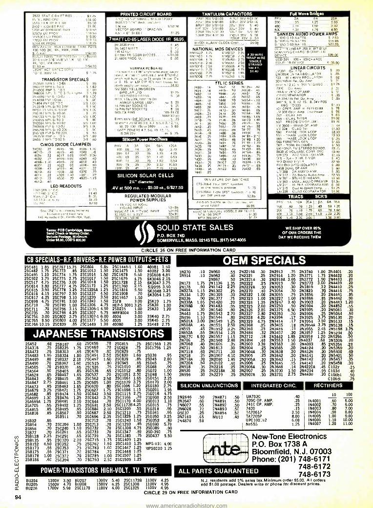
94
2522 STATIC SHIFT R FG 5275 INTEL 8080 CPII 524.50 2518 HEX 37 BIT SR . 55.00 2102.1 1024 8T RAM $1.80 52804K DYNAMIC RAM . . $10.50 5202A UV PROM $10.50 MM5203 UV PROM $10.50
1 702A UV PROM $1075 5204-4K PROM .. 518.95 MINIATURE MULTI -TURN TRIM POTS 100, 500, 2K, 10K, 100K, 200K $.75 each .. .. . . . 3/$2.00 MULTI TURN TRIM POTS Sant. to Bourns 3010 style 3116 "x5 /8 "xt 1/4". 50. 100, I K, 10K, 50K ohms $1.50 ea. ......... 3/$4.00 LIGHT ACTIVATED SCR's TO.18.200V 1A. S 1.75
TRANSISTOR SPECIALS 253585 NPN SI TO-66 S 05 2N3772 NPN Si TO -3 S 1 60 2N4908 PNP SI TO.3 9 1.00 256056 NPN SI TO -3 Dan bngton 0 1.70 255086 PNP Si T0ß2 4/$ 1.00 2914898 PNP TO -66 9 60 25404 PNP GE TO.5 . . . 51$ 1.00 2913919 NPN SI TO -3 RF 5 1.50 MPSA 13 NPN SI T0-92 3/0 1 00 2N3767 NPN Si T0-66 5 .70 2912222 NPN Sn TO.18 .. .... 5/S 1.00 253055 NPN Sn TO.3 $ .80 2N3904 NPN Sn T0-92 5/$ 1.00 2N3906 PNP Sn TO 92 5/$ 1.00 2N5296 NPN SI TO -220 $ .50 2N6109 PNP SI TO-220 $ .55 2N3638 PNP 51 TO 5 5/0 1 00 2565) i NPN 10 92 SI - 3/8 1.00
CIMOS (DIODE CLAMPED) 74CO2 22 4015 95 4035 1.10 74C10- .22 4016- 40 4042- .78
4001 22 4017- 1.05 4047-200 4002- .22 4018 -1.00 4049- 40 4006 -1.20 4019- .22 4050- .40 4007- 22 4022 .95 4066- 230
4009- 42 4027- .40 4071- .22 4010- .42 4028- .88 4076- .70 4011- 22 4029 - 1.10 4081- 22 4012- 22 4030- 22 4520 -1.15 4013- .40
LED READOUTS END 500 -.5" C C
HP 774053" C.C.
NS 33.3 dig. arm,/ DL 141
$1.75 $1.40 51.25 S1 35 57 50
Send 25t for 0111 t.,I,,I I,' tul0,1 Tia and Rectifiers
145 Hampshire St -, Cambridge, Mass.
11:Y144D)Id''1Ìl:IA7A00 4 102P WE 1.2' SINGLE SIDED EPDXY BOARD 1/16" thick. ine,rhed 3.50 ea. ... ... ..... VECTOR BOARD 1" SPACING
n" SHE FT
5/$2.20
Si 75
7 WATT LD -65 LASER DIODE IR $8.95- 3R20 P F E T - $ .45
2N 5457 N FEI $ .45 T1543 UJT 5 .35 ER 900 TRIGGER DIODES 4/$100 2N6028 PROD. UJT 0 65
VERIPAX PC BOARD Tho boon] is a 1/16" single sided paper epoxy board, 4'3'x651" DRILLED and ETCHED which will hold up to 21 single 14 pin IC's or 8, 16, or LSI DIP IC's with busses for power supply connector. $4.00 MV 5691 YELLOW -GREEN
BIPOLAR LED $1 25 FP 100 PHOTO TRANS $ .50 RED, YELLOW, GREEN OR
AMBER LARGE LED's ...ea 5 20 14 PIN DIP SOCKETS $ .25 16 PIN DIP SOCKETS S .28 MOLEX PINS 100/$1.00
1000/S7.50 8 PIN MINI DIP SOCKETS S 75 10 WATT ZENERS 3.9, 4.7, 5.6, 8.2, 12. 15,
18, 22, 100, 150 or 200V a. $ 60 1 WATT ZENE RS 4.7, 5.6, 10, 12, 15,
18 OR 22V ea S .2$
ßf1 YitAOL[H_1L1dYOM. 225F 35V 5:'51.00 4 7UF 35V 4.51 -00 47UF 35V 5/$1.00 SOUP 35V 3'SI. 00 .68ÚF 35V 5/$1.00 22UF 35V 0 40 1UF 35V 5/$1.00 33UF 35V $ 40 2 2UF 20V 5 /S1.00 30UF 6V 5,5100 3.30F 35V 4/51.00 1000E 35V $ 50
150UF 15V $ .50
M /001 ALARM CLOCK CHIP.... $6.00
NATIONAL MOS DEVICES MM1402 - 1.75 MM5057- 2-25 MM1403- 1.75 MM5058- 2.75 MM1404- 1.75 MM5060- 2.75 MM5013- 2.50 MM5061- 2.50 MM5016- 2.50 MM5555- 4.75 MM5017- 2.70 MM5556- 4.75 MM5055- 2.25 MM5210- 105 MM5056 - 2.25 MM5260 1.75
Silicon Power Rectifiers
i
PRV 1A 3A 124 504. 125A 100 06 .14 _30 .80 3.70 200 07 .20 .35 1.15 4.25 400 09 .25 .50 1.40 6.50 600 .11 .30 .70 1.80 8.50 800 .15 .35 00 2.30 10.50
1000 20 .45 1 .10 2. 75 12.50
SILICON SOLAR CELLS 2`Y" diameter
.4V at 500 ma. ... $5.00 ea., 6/$27.50
REGULATED MODULAR POWER SUPPLIES
- 15 VDC AT 100ma 115VAC INPUT .... .. $27.95
5VDC AT 1A. 115VAC INPUT 524.95 12 VDC AT .5 AMP 524.95 IN 4148 1191914/ 15 S1 00
TTL IC SERIES
8 30 WIRE WRAP WIRE
SINGLE STRAND 00 FT. 51.40
7400- .14 7442 -- 52 74125- .40 7401- .14 7445- .70 74126- .40 7402- .14 7446- .70 74151- .70 7403- 14 7447- .70 74153- .65 7404- .18 7448- .70 74154 - 1.10 7405- .18 7450- .20 74155- .70 7406- .20 7472- .30 74157- 70 7407- .25 7473- .30 74161- .85 7408- .21 7474- .30 74164- 05 7409- .21 7475- .49 74165- 1.05 7410- .15 7476- .35 74173- 1.40 7411- .20 7480 .35 74174 .95 7412- .20 7483- .70 74175- .92 7413 .45 7485 .88 74177- .79 7414- .70 7486- .30 74180 .70 7416 -- .25 7489 - 1.85 74181- 2.10 7417- .25 7490- .45 74190 -1.20 7420- .20 7491- .70 74191- 1.20 7425- 28 7492- .50 74192- .85 7426- .25 7493- .45 74193- .85 7427- .30 7494- .70 74194- .85 7430- .20 7495- .70 74195- .75 7432- .25 7496- .70 74196- .88 7437- .25 74107- .32 75324- 1.75 7438- .25 74121- .35 75491- 65 7440- .16 74123- 65 75492- 65 7441- 95
MINIATURE DIP SWITCHES
CTS 206 -4 Four SPST switches In one mintdos package. . . 51.75
CTS 206.6 Eight SPST switches In a 16 pm DIP package $2.85
AV 5.1013 -030K se, /par., par. /ser., une.
versal UART. 56.95
ALCU MINIATURE TOGGLE SWITCHES MTA 106 SPDT $1 20 MTA 206 DPDT $1.70
nll\r.'l17vLr. PRV ?A 6A 25A 201) 9 1.25 2.00 400 1 1 5 1.50 3.00 600 1 35 1.75 4.00
SANKEN AUDIO POWER AMPS Si 1010 G 10 WATTS
$
7.50 Si 1020 G 20 WATTS $15.95 Si 1050 G 50 WATTS 527.95 CCD 110 LINEAR 256 XI BIT SELF SCANNING CHARGED COUPLED DEVICE $99.00 CCD 201 100 x 100 CHARGE COUPLED DEVICE... .. . 0135.00
LINEAR CIRCUITS LM307 -Op. Amp......... S .30 LM 309K 5V 1A REGULATOR .. $ .95 723 - 40 0 40VV REGULATOR .. $ .50 301 /748'H1 Per. Op. Amp 5 .31
320T 5.12,15. or 24V NEG REG $1.25 7090 Op. Amu, S .31 741A or 741C OP AMP. S .31
710 COMPARATOR S .35 CA 3047 HI Pet. Op. Amp.. - . S .95 3407 5, 6, 8, 12, 15, 18, 24V POS
REG. TO-220 101 OPER. AMP, HI PERFORM LM 308 Oper. Amp., Low Power . .
747 - DUAL 741 556 - DUAL TIMER 537 - PRECISION OP. AMP LM 3900 - QUAD OP. AMP .. .
LM 324 - QUAD 741 560 - PHASE LOCK LOOP ... .
561 - PHASE LOCK LOOP ... .
565 - PHASE LOCK LOOP ... .
566 FUNCTION GEN 567 - TONE DECODER LM 1310N FM STEREO DEMOD. 8038 IC VOLTAGE CONT. OSC. LM 370 - AGC SQUELCH AMP. 555 - 2µs - 2 HR. TIMER 553 QUAD TIMER FCD 810 OPTO- ISOLATOR 1458 DUAL OP AMP. LM 380 - 2W AUDIO AMP. .
LM 377 - 2W Stereo Audio Amp_ LM 381 - STEREO PREAMP. .
LM 382 - DUAL AUDIO PREAMP LM 311 - HI PER. COMPARATOR LM 319 - Dual HI Speed Comp. .
CM 339 - QUAD COMPARATOR
$1.10 S 75 $.95 S .65 51.00 $1 70
$ 49 $1.50. $2.00 $2.00 $1.25 51.65 51.50 52.75 $3.90 $1.15 $ .45 $2.50 $ .80 S .60 $ .95 52.50 $1.50 $1.50 S .90 $1.25 S1 50
TRIACS SCR'S PRV 1A 10A 25A 1.5A 6A 35A 100 .40 .70 1.30 .40 .50 1.20 200 .70 1.10 1.75 .60 .70 1.60 400 1.10 1.60 2.60 1.00 1.20 2.20 600 1.70 2.30 3.60 1.50 3.00
Tanns: FOB Cambridge, Mass. Sand Chock or Money Order. Include Postage, Minimum Order á6.O0, COO'S $20.00 4 5
SOLID STATE SALES P.O. SOMERVILLE
BOX 74D MASS. 02143 TEL. (617) 5474005
WE SHIP OVER 95% OF OUR ORDERS THE
DAY WE RECEIVE THEM
CIRCLE 36 ON FREE INFORMATION CARD
CB SPECIALS -R.F. DRIVERS -R.F. POWER OUTPUTS -FETS 2SC481 2SC482 2SC495 2SC502 2SC517 2SC614 2SC615 2SC616 2SC617 2SC699 2SC710 2SC711 2SC735 2SC756 2SC765 2SC 766
1,85 1.75 1.10 3.75 4.75 3.80 3.90 4.15 4.25 4.75
.70
.70
.70 3.00 9.50
10.15
2SC767 15.75 2SC773 .85 2SC774 1.75 25C775 2.75 25C776 3.00 2SC777 4.75 2SC778 3.25 25C797 2.50 25C798 3.10 2SC781 3.00 2SC789 1.00 2SC796 3.15 2SC799 4.25 2SC802 3.75 2SC803 4.00 2SC839 .85
2SC866 5.85 2SC1013 1.50 2SC1014 1.50 2SC1017 1.50 2SC1018 1.50 2SC1173 1.25 2SC1226A 1.25 2SC1237 4.50 25C1239 3.50 2SC1243 1.50 2SC1306 4.75 2SC1306-1 4.90 2SC1307 5.75 25C1307-1 6.00 2SC1377 5.50 25C1449 1.30
2SC1449 -1 1.60 2SC1475 1.50 2SC1678 5.50 2SC1679 4.75 2SC1728 2.15 2SC1760 2.15 2SC1816 5.50 25C1908 .70 2SC1957 1.50 2SF8 3.00 HEP -S 3001 3.25 25D235 1.00 MRF8004 3.00 4004 3.00 4005 3.00 40080 1.25
40081 1.50 40082 3.00 2SC608 4.85 SK3046 2.15 SK3047 3.75 SJ2095 3.50 SK3048 3.25 SK3054 1.25
25K19 1.75 2SK30 1.00 2SK33 1.20
3SK40 3SK45 3SK49
2.75 2.75 2.75
JAPANESE TRANSISTORS 2SA52 254316 2SA473 25A483 254489 254490 2SA505 2SA564 2SA628 2SA643 25A647 2SA673 2SA679 2SA682 254699 2SA699A 254705 2SA815 2SA816
2SB22 25854 25856 25877 25B128 2SB135 2SB152 258173 256175 256178 2SB186
.60 .75 .75
1.95 .80 .70 .70 .50 .65 ,85
2.75 .85
3.75 .85
1.30 1.75
.55
.85
.85
.65
.70
.70
.70 2.25
,95 4.50
.55 .55
1.00 .60
258187 258235 256303 258324 2SB337 258367 2SB370 258405 25B407 2SB415 2SB461 25B463 258471 258474 2SB476 25B481 2SB492 258495 258507 2SB511
2SC206 2SC240 2SC261 2SC291 2SC320 2SC352 2SC353 2SC371 2SC372 2SC394
.60 1.75 .65
1.00 2.10 1.60
.65
.85 1.65 .85
1.25 1.65 1.75 1.50 1.25 2.10 1.25 .95 .90 .70
1.00 1.10 .65 .65
2.00 .75 .75 .70 .70 .70
2SC458 2SC460 2SC478 2SC491 2SC497 2SC515 2SC535 2SC536 2SC537 2SC563 2SC605 2SC620 2SC627 2SC642 2SC643 2SC644 2SC681 2SC684 2SC687 2SC696 2SC712 2SC713 2SC732 2SC733 2SC739 2SC715 2SC762 2SC783 2SC 784 2SC785 2SC793
.70
.70
.80 2.50 1.60 .80 .75 .65 .70
2.50 1.00 .80
1.75 3.50 3.75
.70 2.50 2.10 2.50 2.35
.70
.70
.70
.70
.70 1.75 1.90 1.00
.70 1.00 2.50
25C815 2SC828 2SC829 2SC830 2SC839 2SC945 2SC1010 2SC1012 2SC1051 2.50 2SC1061 1.65 2SC1079 3.75 2SC1096 1.20 2SC1098 1.15 2SC1115 2.75 2SC1166 -70
2SC1170 4.00 2SC1172B4.25 2SC1209 .55 2SC1213 .75 2SC1226 1.25 2SC1243 1.50 2SC1293 .85 2SC1308 4.75 2SC1347 .80 2SC1383 .75 2SC1409 1.25 25C1410 1.25 2SC1447 1.25 2SC1448 1.25 2SC1507 1.25 2501509 1.25
.75 2SC1569 .75 2SC1756 1.25 .75
1.60 .85 .65 .80 .80
1.25
2SD30 2SD45 2SD65 2SD68 2072 2SD88 2SD151 2SD170 2SD180 250201 2SD218 2SD300 2SD313 2SD315 2SD318 2SD341 2SD350 2SD352 2SD380 2S0389 2SD -390 2SD4
MMPS
.95 2.00
.75
.90 1.00 1.50 2.25 2.00 2.75 1.95 4.75 2.50 1.10 .75 .95 .95
3.25 .80
5.70 .90 .75
5.50
OEM SPECIALS 1N270 .10 1N914 .10
2N173 2N178 2N327A 2N334 2N336 2N338A 2N398B 2N404 2N443 2N456 2N501A 2N508A 2N555 2N652A 2N677C 2N706 2N706B 2N711 2N 711B 2N 718 2N718A 2N720A 2N918 2N930 2N956
1.75 .90
1.15 1.20 .90
1.05 .90 .30
1.75 1.10 3.00 .45 .45 .85
6.00 .25 .40 .50 .60 .25 .30 .50 .35 .25 .30
2N960 2N962 2N967 2N1136 2N1142 2N1302 2N1305 2N1377 2N1420 2N1483 2N1540 2N1543 2N1544 2N1549 2N1551 2N1552 2111554 2N1557 2N1560 2N1605 2N1613 2N1711 2N1907 2N2060 2N2102 2N2218 2N2218A 2N2219
.55
.40
.50 1.35 2.25
.25
.30 ,75 .20 .95 .90
2.70 .80
1.25 2.50 3.25 1.25 1.15 2.80 .35 .30 .30
4.10 1.85 .40 .25 .30 .25
2N22194 .30 2N2221 .25 2N22214 .30 2N2222 .25 2N2222A .30 2N2270 .40 2N2322 1.00 2N2323 1.00 2N2324 1.35 2N2325 2.00 2N2326 2.85 2N2327 3.80 2N2328 4.20 2N2329 4.75 2N2368 .25 2N2369 .25 2N2484 .32 2N2712 .18 2N2894 .40 2N2903 3.30 2N2904 .25 2N29044 .30 2N2905 .25 2N29054 .30 2N2906 .25 2N29064 .30 2N2907 .25 2N2907A .30
SILICON UNIJUNCTIONS
2N2646 2N2647 2N6027
N6 2028 D5E37 2N2160 2N4870
.50
.60
.55
.70
.25
.65
.50
2N4871 2N4891 2N4892 2N4893 2N4894 MU10
.50
.50
.50
.50
.50
.40
2N2913 .75 2N2914 1.20 2N2916A 3.65 2N3019 .50 2N3053 .30 2N3054 .70 2N3055 .75 2N3227 1.00 2N3247 3.40 2N3250 .50 2N3375 6.50 2N3393 .20 2N3394 .17 2N3414 .17 2N3415 .18 2N3416 .19 2N3417 .20 2N3442 1.85 2N3553 1.50 2N3563 .20 2N3565 .20 2N3638 .20 2N3642 .20 2N3643 .15 2N3645 .15 2N3646 .14 2N3730 1.50 2N3731 2.75
2N3740 2N3771 2N3772 2N3773 2N3819 2N3823 2N3856 2N3866 2N3903 2N3904 2N3905 2N3906 2N3925 2N3954 2N3954A 2N3955 2N3957 2N3958 2N4037 2N4093 2N4124 2N4126 2N4141 2N4142 2N4143 2N4220A 2N4234 2N4400
INTEGRATED CIRC.
UA703C 709C OP. AMP. 741C OP. AMP. 7400 TA7061P TA7205P UPC1001h2 Ne555
.40
.25
.25
.15 3.50 8.00 6.00 1.25
1.00 2N4401 1.75 2N4402 1.90 2N4403 3.00 2N4409
.32 2N4410 .70 2N4416 .20 2N4441 .85 2N4442 .90 .20 2N4443 1.20 .20 2N4852 .55 .20 2N5061 .30 .25 2N5064 .50
3.75 2N5130 .20 3.50 2N5133 .15 3.75 2N5138 .15 2.45 2N5198 3.75 1.25 2N5294 .50 1.20 2N5296 .50 .60 2N5306 .20 .85 2N5354 .20 .20 2N5369 .20 .20 2N5400 .40 .20 2N5401 .50 .20 2N5457 .35 .20 2N5458 .30 .45 C103y .25 .95 C103d .20 C106b1
C106di
.20
.20
.20
.20
.25
.75
.85
.40
.50
.75
RECTIFIERS
N4001 N4002 N4003 N4004 N4005 N4006 N4007
10
.60
.70
.80
.90 1.00 1.10 1.20
100
5.00 6.00 7.00 8.00 9.00
10.00 11.00
37 New -Tone Electronics MPS-U31 4.00 P.O. Box 1738 A
a ° °° 1.25 Bloomfield, N.J. 07003 Phone: (201) 748 -6171
748 -6172 748 -6173 POWER- TRANSISTORS HIGH -VOLT. TV. TYPE
811204 BU205 BU206
1300V 3.90 1500V 4.70 1700V 5.90
BU207 1300V BU208 1500V 2SC1170 1100V
5.40 2SC1172B 1100V 4.25 6.25 2SC1308 1100V 4.95 4.00 2SC1325 1100V 4.95
CIRCLE 29 ON FREE INFORMATION CARD
ALL PARTS GUARANTEED N.J. residents add 5% sales tax.Minimum order $5.00. All orders add $1.00 postage. Dealers write or phone for discount prices.
www.americanradiohistory.com
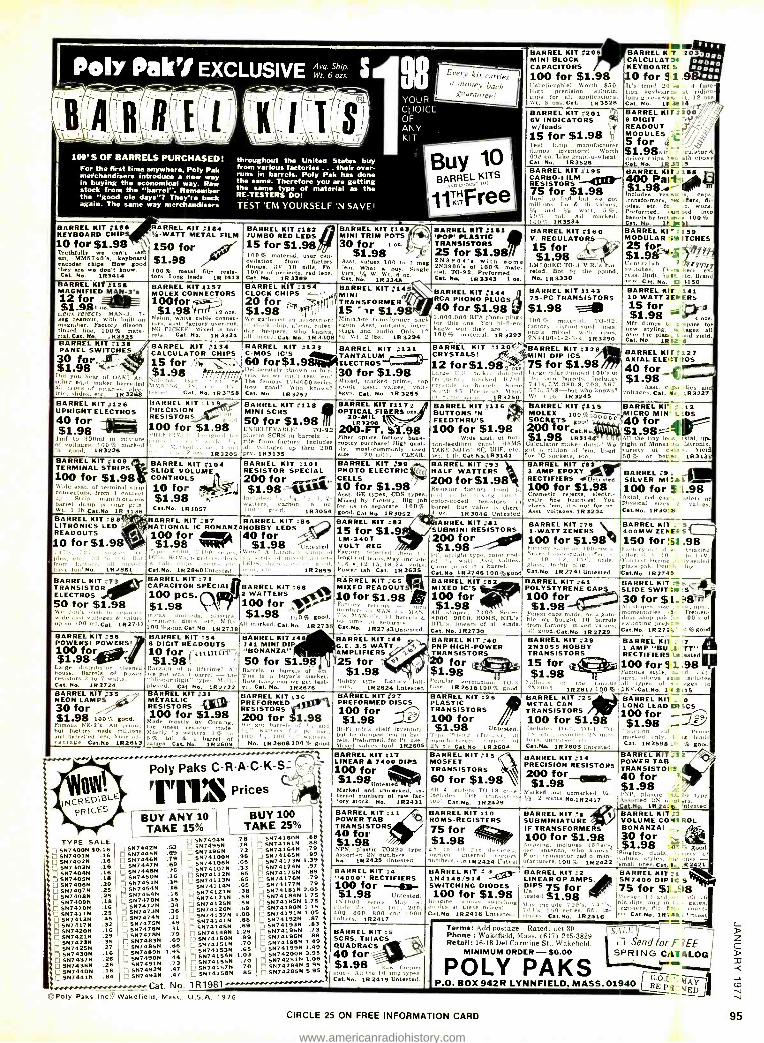
Every kit carries a money back
guarantee!
100' S OF BARRELS PURCHASED! For the first time anywhere, Poly Pak merchandisers introduce a new way in buying the economical way. Raw stock from the "barrel''. Remember the "good ole days"? They're back again. The same way merchandisers
throughout the United States buy from various factories ... their over- runs in barrels. Poly Pak has done the same. Therefore you are getting the same type of material as the RE- TESTERS DO!
TEST 'EM YOURSELF 'N SAVE!
Buy 10 BARREL KITS
1íK "Free B ARREL KIT #19 KEYBOARD CHIP 10 for $1.98
we t em, M1M$740'e, keyboard
encoder chips. How good are they a don't know.
Cat. No. 1R3414
BARREL KIT #164 Y. -WATT METAL FILM
150 for $1.98 100% meal elm resis- tors. Long tende. 1R 1413
BARREL KIT #192 JUMBO RED LEDS 15 for $1.98 C00 % material, user cau-
front factory dumps, 3V 10 mils. For 100's of eenlects, red lens. Cat. Na. 1R 3389
B ARREL KIT #163 MINI TRIM POTS 30 for I...
$1.98
B ARREL KIT #156 MAGNIFIED M N -3's 12 for 11.9ß1 n =
Lens r MAN-3, 7- eeg reactant, with built -ne magnifier. Factory diecoe- Onued lion, 10090 mate- rial, Cet. No. .93325
ARREL K 138 PANEL SWITCHES 30 for.. -K' $1.98 11:;4--.- Did you hear of OAK? A, other earl maker barrelled all trio iide.fetc. 193268
BARREL KIT #157 MOLEX CONNECTORS 100for- S1.98 i ose.
Nylon, white cable connec- tors. asst. factory over -run. Ní FICKEEI Mixed in bar- rel s_ Cat- No, 1R 3324
BARREL KIT :154 CLOCK CHIPS - 20 $1 98fi; . ¡! We gathered an assortment of clock chip. alarm, calen- dar, beepers, who knows, ull' mixed. Cat No. 19 3308
nn values ion to 1 mag What buy. Single turn, t/ W. Wt. 8 0 Cat No. 1R 3345
BARREL KIT #145 MINI TRANSFORMER 15 "1r $1.98
KIT #161 'POP' IC
ISTORS 25 for $1.93 2N3904's with some 2N3908's f 100% ate - rial. TO -92. Preformed. Cat. Na 193343 1 ea.
..:=1wAEff BARREL KIT #205 MINI BLOCK CAPACITORS 100 for $1.98 I'nbelievablel Worth $50. High precision submini caps for all applications. Wt. 3 ors. Cat. IR 3528 BARREL KIT ## #201 6V INDICATORS
/leads 15 for $1.98 N
Test lamp manufacturer dumps inventory! Worth 69e ea. Like grain -o- wheat. Cat. No. 193526
MEE BARREL K 203 CALCULATOR KEYBOARt S
0 for 31 .9 It's true! 20 I- 4 func- tion keyboar!, t ridicu- lous give -Iva.. t. 12 ozs Cat, No. IF 3E14 BARRELKIr IO0/ 9 DIGIT j77;'ß READOUT MODULES 5 for ct
$í.98n alator& driver chips I _- 'h epoxy Cat No 1R3- A
BARREL KIT #195 BARREL K1r 88 CARBO -FILM wrfM. 400 Part. RESISTORS Va S1.98...- 75 for $1.98 Includes tee e Hard to nod; but we got transformers, r Revs di- millions. Lo & Hi values. des. etc. fa - work. / 0<. t' and ' watt, 5 Preformed, se sad winto 10 tul. All marked. barrels by feet sr. s. 100 % 1011';. 193534 Cat. No. l$.
BARREL RI ra 159 MODULAR ':K ITCHES
$198 rr_- Centralab I rip, witches. TA,. ken/ cess. Daet, oplc. rte. Brand new. Cat. No, 11 3150
BARREL KIT #160 V. REGULATORS 15 for ,I( $1.98
LM309KC TO -3 V,R,'s bar- reled. Bot by the pound, No. 19 3330
Minia7ure transformer back again. Asst. outputs, inter - stage and audio. Only 1" sa. \5t. 2 lbs. 1R3294
BARREL PHONO PLUGS
KIT #144
40 for $1.98 1,000,00) RCA phono plugs for omis u e. You hi -li -ers know wmt they are . . ,
10090 material. IR 3293
B ARB EL KIT #134 BARREL KIT CALCULATOR CHIPS C -MOS IC'S 15 for î 91 ate 60 for$1.98
:133
I181ibet-,Oeb' thrvwn to bar $1.98 >tf;7rrff¡¡frele, n t t N,,temai type 'n
e The famous ('114000 serie,. MM. 57:ìb. :in, r., lin- How good? Who knnu.s ?. tted. Cat. No. 1R3258 Cat, No. 1R3257
BARREL KIT #131 TANTALUM ELECTROS 30 for $1.98 Mixed, marked prime, toy grade asst. values, volt- ages. Cat. No. 1R 3255
BARREL KIT :'143 75 -PC TRANSISTORS
$1.98 100 ^A material. TO -92, factory discontinued lines, ono's mixed with ntrns. 2N4400- 1- 2 -3 -4. 193290
BARREL KIT ?130 BARREL KIT :129 CRYSTALS! - MINI DIP ICS
12 for$1.98 75 for $1.98 Large maker dumped Large
¡MO dumped 100's e1
fr, ked II /01' lbs into barrels. Includes 1.rrel,. Some 741s, LM- 380 -8, 703, 567.
v ,rtl, - I' .. f Man, 555, 558 -hut who knows? 'n - íR3250 W. 1 lb. 112 3245
BARREL IRE . 141 10 WATT 1Ee ERS 15 for $1.98 °. 4
Mfr etas styling,
r :sere ail ove x. dey 1l over the Dlac,. R Cod yield. Caf. No. 1p L.
BARREL KIF#127 AXIAL ELEt:TIIOS 40 for , $1.98-
.Asst. c:ra ,nee and voltages. Cat. Se, 193227
BARREL KIT #126 UPRIGHT ELECTROS 40 for $1.98
lmf to 300mí in mixture of voltages. 100!7 marked 'n good. 1R3226
BARREL KIT #109 TERMINAL STRIPS 100 for $1.98
adre
asst. of terminal c rectors,. from contact
p. Strip manufacturers barrel dump isn
v
mr gain. Wt. 1 lb. Con Ne 1R 3136 BARREL KIT -88t LITRONICS LED READOUTS
10 for $1.98
BARREL KIT -119 - RRSISTION RESISTORS,- 100 for $1.98
I .,/cl 1R 3205
BARREL KIT #118 MINI SCRS 50 for $1.98 IT UNBELIEVABLE! TO -92 Plastic SCRS in barrels ... rite from factory. Includes all voltages up thru 200 pry. íR3135
B ARREL KIT #117 OPTICAL FIBERS ode.
20-MIL í
200 4FT R3208
L98 Fiber optics factory bank- ruptcy purchase! High qual- ity.
m ost- commonly d
:lee í20 -mill, CLEAR.
BARREL KIT #116 BUTTONS 'N FEEDTHRU'S 100 for $1.98
Wide asst. ut but - ton-feedthru caps! HAMS TAKE NOTE! RF, UHF. etc. Wt. 1 Ib. Catbo,1R3141
BARREL KIT #115 MOLEX 100 10óo SOCKETS good 200 More., No 11trm $1.98 1931 !
I I
Calculator maker dump! We gut n riion of 'em. Used for IC sockets, etc.
o
B ARREL KIT #104 SLIDE VOLUME CONTROLS
10 for $1.98 CtNe. 19 1057
BARREL KIT :101 RESISTOR SPECIAL 200 for $1.98_
Ioslude,: t 17a e. I.2- tiers, carbon. n ,
loo good, íR3054
BARREL KIT #99 PHOTO ELECTRIC EIUI(1p`
CELLS 10 for $1.98 Asst. GE types, CDS types. Mixed by factory. Big job for on to separate. 100 % good. Cat.No. 1R3052
plc Ito fr facto,. . Il -/I h:avc fan' No 1R2861
BARREL KIT :87 BARREL KIT :86 is EL KIT :83 NATIONAL IC BONANZAHOBBY LEDS 100 for 40 for 15 for $1.9 $1.98 ' $1.98 Untested VOLT O REG
gi.Ic,.e l " all kimm.l- At inmed il imele length of leads,May memo A e. le. hip., Iii LEDs, .1 .modi g. il. t, 6. e, 12. In. 18. 24 volts
ColSe. IR 2660Untesl ed. " 192855 Comer tab Cat. 192635
BARREL KIT 793 HALF WATTERS 200 for $1.98 Resistor factory
r ied to
cnil h, g luu, olor coded ' resistors in
barrel. But value is there 4 oz. 193046 Untested
BARREL KIT #63 3 AMP EPDXY ntjam RECTIFIERS Untested 100 for $1.98 Cosmetic rejects electri- cally fine business! You check 'ern, It's not for us, Aset. voltages. 1R 3204
BARREL KIT' , 12 ICRO MIN' iL:DS
40 for Si 98= ._ All the tiny lei .s
s
ia1,.110a fight of Monda rate Litronil,
variety of cala s. field 50% or bat ex_ 1R313
BARREL 09 SILVER MI :J s5
100 for í,L.98 Axial, red r r a iety of physical sizes d values. Cat.No. 1R301á
ARREL KIT #81 SUBMINI RESISTORS 200 for $1.98
11 upright type. color cod- ed. watt. Asst values. Came to on a barrel. Cat.No íR2746100 %good
BARREL KIT :76 1 -WATT ZENERS 100 for $1.98 Fu, tuo -mw 's
k. sa rtes
IO, sl .. agi . \' under glass. Docble plug. Cat.No. 1R 2741 Untested,
BARREL KIl _ 5 400MW ZENEaS 150 for .98 Factor, out ,.f a Amazing lire: t,. In to 15V. You test. Ilemme 'y sealeA glass cek. Dari .1 lug. Cat.No. 1R2749
BARREL KIT #73 TRANSISTOR ELECTROS 50 for $1.98 K' e don't w1.11 separat,
BARREL KIT #71 CAPACITOR SPECIAL 100 pCS. $1.98
BARREL KIT 768 2 WATTERS 100 for
ide text voltages & calo, nohb US, 11 -. $1.98 100% good. up e, 300 mf,Cat- 1R2747 100 %good Cat Not 192738Aí1
marked. Cat.No. 1R2735 BARREL KIT 756 POWERS! POWERS! 100 for $1.98
Large distributor e leaned
u Barrels of power
resistors 3 tu 7 watts. Cat No. 1R2724 BARREL KIT #35 NEON LAMPS 30 for $1.98 100% good. Famous NE-2's. All primY but factory made millions anti barreled em, Your ad vantage Cat.No 192613
BARREL KIT #5 8 DIGIT READOUTS 10 for ¡ttulicl $1.98.
Bargain of a lifetime! Al! we got was 1 barrel - the hlisdur digit" types, Molt, -
ple.vcd. Cat. No. 1R2722 BARREL KIT #31 METALLIC RESISTORS 100 for $1.98
the finest Made mostly by
o n
wooers Muscly 1 n 5%Ot toi. & a barrel of values. Cet No. 192609
BARREL KIT #4 741 MINI DIP "BONANZA"
BARREL KIT :65 MIXED READOUT 10 for $1.98 Pastor, returns
h rs i
MA N 4hr rel s
A N e me ti
110
Cat.No, 182733 Untested.
BARREL KIT #82 MIXED IC'S 1$00 for ligok All shapes 7400 Serie, 8000, 9000. ROMS. RTL s, DTL's, lineors of all kinds, Cat. No. 192730
BARREL KIT 061 POLYSTYRENE CAP 100 for ®® $1.98
Finest caps made Asa gam- ble we bought 10 barrels from factory. mixed values; all good. Cat.No. 1R2729
BARREL KIT :! II SLIDE SWIT::5 30 for $L.f8P All msoroneaptasies.
, mtp,lt.l 1 'Tre
do us .shop pak - .00 seof '' ching PruJa_--
CaLNo. 1112725, 0 90 good
50 for $1.98 Barrels It barrels of em This is a buyer's market. Huw many can we get test- ed. Cat. No. 1R2626
BARREL KIT #48 G.E. 3.3 WATT
MPLIFIERS 25 for
$1.98 Hubby type. factory fall
1
BARREL KIT #40 PNP HIGH -POWER TRANSISTORS
for $1.98
- Popular germanium TU.:i cane íR2618100^. good outs, 1R2624 Untested
BARREL KIT #30 PREFORMED RESISTORS 200 for 1.98 lA e harrnl,
m t
.1 find fur pt.
1 í1.10í1 fret. No, 1112608100% good
BARREL KIT #27 PREFORMED DISCS 100 for $1.98
111-Fi mfr shelf inventor, but he dumped m in bar- rels. Preformed, for PC u Mixed values too! 1R2605
BARREL KIT PLASTIC TRANSISTORS 100 for $1.98 Untested.
t >, I) t I r,. rl n
nufact rer, arm, v t 25 L's. Cat.No 1122604
BARREL KIT #39 2N3055 HOBBY TRANSISTORS 15 for $1.98
Fallu u;.. of the tnmou.s 25'1110,5. 1R26171009 BARREL KIT :25 METAL CAN TRANSISTORS / 100 for $1.9 In I!s T1 o Tt) 1, úU I - ,1 2N 11L1111.
he rs n
narked c
Cat.Ns 1R2603Untested.
BARREL KIl - '7 1 AMP "BU .11 TT" RECTIFIERS Is .ested
100 for 9.1.98tl Famous style, a td. v R- ages, silicon. a no includes all type., al
s -.5gex lit 1KV.Cat.No. 1 I g í1S BARREL KIl - O LONG LEAD EN SCS 100 for - $1.98 .- 'a,
n -al Yarn
mark,' 1 sr leads Cat. 1R2598 IO, 7o goon
TYPE SALE 5574005 50.16
L 5574015 .16 5N7402N .16 51574035 .16 51474045 .16 SN7405N .18 5N7406N .20
L7 5N74075 .25 L 5N7408N .25 L 5N74095 .18 D SN7410N .16 L 5N7411N .25
SN7413N .45 SN7317N .32 SN742ON .16 SN7421N .29
L SN7423N .35 L 5147425N .27
SN7430N .16 D 5N7437N .26
SN7436N .26 L7 SN7440N .16
SN7441N .84
O Poly
Poly Paks C- R- A- C -K -S: It \l' \'I Prices
BUY ANY 10 TAKE 15%
5N7442N .53 D 5574455 -69
5N7446N -79 L] 5N7447N .69 L 5974485 .76
SN7450N .16
5574515 .16 [] S5745414 .16
5574645 .16 5574705 .45
-5574725 .34 557473N .36 SN7474N .31 5574755 .49
--5574765 .31 5574785 .79
L 5N7483N .69 5574855 .86 5574899 1.95
-.557490N .44 5574915 .73 5574925 .47
.5N7493N .47
,.,;N7494N
N7495N 5N7496N
' 55741005 5H74106N 55741075
L 5574112N 55741135 55741145 5N74121N 5N74123N
'._-,5N74125N 5N74126N 55741325
L SN74141N 5N74145N
[i, 5574148N !`55741505 Li 55741515
55741535 55741545
L 5N74155N
BUY 100 TAKE 25%
.78 55741605 .88
.78 55741615 .88
.72 514741645 .79
.98 55741655 .99
.65 L7 55741735 1.39
.33 SN741745 .97
.65 ] 5574175N .89 .65 5574176N .79 .65 C7 5N74177N .79 .38 D SN74181N 2.05 .59 l 5N74184N 1.75 .59 L_ 5N74185N 1.75 .59 , 5N74190N 1.15
1.00 5N74191N 1.05 .88 5N74192N .87 (((
.69 5574393N .83 1.29 55741955 .73
.99 5574196N .88
.70 Cl 5574198N 1.49
.65 55741995 1.49 1.03 55742005 3.95
[] 55742515 1.09 55742845 5.95
D 5574285K 5.05
.70 L, SN74157N .70
5N74158N .85
Cat. No. 1R1981 Paks Inc` 'Wakefield, Mass., U.S.A. 1976
BARREL KIT #17 LINEAR 7400 DIPS 100 for $1.98Unteate
.
Marked and uv raed. in-
terna) u bere of ra fac- tory stock. No. 192431
BARREL KIT 713 MOSFET TRANSISTORS 60 for $1.98 All 4 lenders TO- 1 F ,
inek.des Utir transi s t, o, too! Cat -No. 1R2429
BARREL KIT :11 POWER TAB TRANSISTORS 40 for $i.9Btic 70220 type. Assorted 2N umbers No. 1R2425 Untested.
BARREL KIT #10 ROMS -REGISTERS
75 for $1.98
to 2.ked, sr 4 ifnternal If e ee torv numhers,, vo 1R2424rCntest
BARREL #14 P RECISION
KIT RESISTORS
200 for $1e.98 -
Marked'ann unmarked '/ .
t /r, 2 etta, Ne 192417
B ARREL KIT #e SUBMINIATURE IF TRANSFORMERS 100 for $1.98 :Amazing. ncludes 455kc,
who ho diknnw,s? úrunt transistor n an.
fnrturera. 100% íR2422 BARREL KIT #4 4000" RECTIFIERS
100 for - .-®- $1.98 Untested.
1N.lunn ie Sta in- clude 9. y
0 inn, 200. 400. 600. 800 and 1000 volters. 1R2417
BARREL KIT 7 3 1N4148 /914 moi! SWITCHING DIODES 100 for $1.98
Imagine e _ ching diode th, Cat.No. 1 R 2418 Untested.
BARREL KIT #S SCRS, TRIALS QUADRACS 40 for $1.98 Itaw factory
ta: All the 10 amp types. Cat. No. 1 9 2419 Untested.
B ARREL KIT :2 LINEAR OP AMPS, DIPS 75 for ir red $1.98 Mnv include 709's, 741'ss, 70:1 s, 000 ser e s. 5f. i
rludes Cat -No. íR2416
BARREL KIrTI r- POWER TAB TRANS ISTOIIS.. 40 for $1.98 ri! P.'P. -la.stic 'L -_e 'pe. Assorted "N rn/rns. /y Cat -NO. IR 2421jß tested. VOLUM KIT I VOLUME CO NB ROL BONANZA! 30 for 4, $1.98 :O? good
Singles, dual. of valluues4 styles, ^u 'fin -
s 11 ne.. CELLE,.R 21 BARREL KIT `1 SN7400 DIP ICS
Terms: Add postage Rated 1 net 30 Phone : Wakefield, Mass. (617) 245 -3829 Retail: 16 -18 Ilel Carmine St., Wakefield,
MINIMUM ORDER -58.00
POLY PAKS
75 for $3 .98 Alarked 1 ! rd Lill I0
a n dips. m
'
n I. . gates, egis flip f, -
ers, Cat.No, 1R:41 , t 0íe01
s'1LF Send for F SEE
SPRING C /l1lALOG
P.O. BOX 942R LYNNFIELD, MASS. 01940
CIRCLE 25 ON FREE INFORMATION CARD
C.O.I-,'., HY VED 1
95
www.americanradiohistory.com
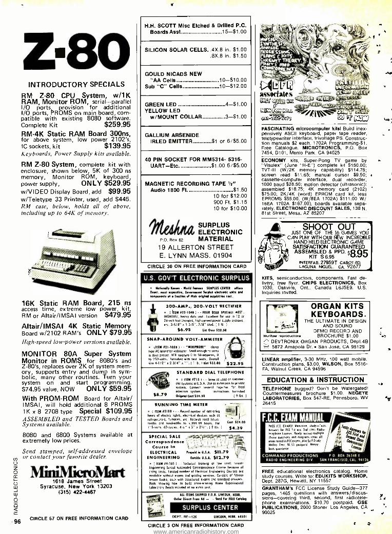
Z80 INTRODUCTORY SPECIALS
RM Z -80 CPU System, w/1K RAM, Monitor ROM, serial - -- parallel I/O ports provision for additional I/O ports, PROMS on main board, com- patible with existing 8080 software. Complete Kit $259.95 RM -4K Static RAM Board 300ns, for above system, low power 2102's, IC sockets, kit $139.95 Keyboards, Power Supply kits available.
RM Z -80 System, complete kit with enclosure, shown below, 5K of 300 ns memory, Monitor ROM, keyboard, power supply, ONLY $529.95 w /VIDEO Display Board, add $99.95 w /Teletype 33 Printer, used, add $445. RM case, below, holds all of above, including up to 64K of memory.
16K Static RAM Board, 215 ns access time, extreme low power, kit, RM or Altair /IMSAI version $479.95
Altair /IMSAI 4K Static Memory Board w/2102 RAM's ONLY $79.95 High -speed low-power versions available.
MONITOR 80A Super System Monitor in ROMS for 8080's and Z -80's, replaces over 2K of system mem- ory, supports entry and dump in sym- bolic, many other routines. Turn your system on and start programming. $74.95 value, NOW ONLY $59.95 With PROM -ROM Board for Altair/ IMSAI, will hold additional 8 PROMS 1K x 8 2708 type Special $109.95 ASSEMBLED and TESTED Boards and Systems available.
8080 and 6800 Systems available at extremely low prices.
Send stamped, self-addressed envelope or contact your favorite dealer.
o
cc 1618 James Street
w Syracuse, New York 13203 (315) 422 -4467
O
cc
96 CIRCLE 57 ON FREE INFORMATION CARD
H.H. SCOTT Misc Etched & Drilled P.C. Boards Asst 15 -$1.00
SILICON SOLAR CELLS..4X.8 in. $1.00 .8X.8 in. $1.50
GOULD NICADS NEW "AA Cells 10- $10.00
Sub "C" Cells 10- $12.00
GREEN LED 4 -$1.00 YELLOW LED
w /MOUNT COLLAR 3 -$1.00
GALLIUM ARSENIDE IRLED EMITTER $1 or 6/$5.00
40 PIN SOCKET FOR MM5314- 5316 - UART -Etc. $1.00 6/$5.00
MAGNETIC RECORDING TAPE '/2" Audio 1800 Ft. $1.50
10 for $12.00 900 Ft. $1.15 10 for $10.00
*lied= SURPLUS ELECTRONIC
P.o. Box 62 MATERIAL 19 ALLERTON STREET E. LYNN MASS. 01904
CIRCLE 30 ON FREE INFORMATION CARD
U.S. GOV'T ELECTRONIC SURPLUS
Notionally Mown - World Femorr. SURPLUS CENTER offers finest, most expensive, Government Surplus electronic units and
components at a fraction of their original acquisition cost.
300 -AMP., 200 -VOLT RECTIFIER
( ITEM #22 -1048 ) FOUR STAR SPECIALI WEST -
INGNOUSE, heavy duty unit- Excellent for use In 12 or
24 -volt fast chargers, high current power supply Systems, etc. 3 -5/8" x I -3/8 ". 7/8" stud. 11 Ib. )
$6.95 List Over 520.00
SNAP -AROUND VOLT -AMMETER
(ITEM #211028 I " MINIPROBE" clamp nl®t, type AC ammeter -voltmeter. Small enough to carry M shirt pocket. Will measure 0 to 50- omperes, 0 . to 250- volts. Furnished with test lends. Overall
site 4-1/2" x 2 -3/4" o 1 ". 1
1 lb. I List 533.00 $22.95
STANDARD DIAL TELEPHONE 't
I TIN 11715 ) Same os used on commer- i v cial systems in U.S.A. Use as extension to private
111 _ system. Connect several together for local
intercom system. Instructions furnished. 88.79 Original Cost 524.50 (9 lbs. I
RUNNING TIME METER
( ITEM #2188 I Record number of operating reR i hours of electric lights, electrical devices such as
refrigerators, furnaces. etc. Records total hours, tenths and hundredths to 9,999.99 hours. For Coat 529.00
115-volts, 60- cycles. 4'6 " a 3" x 2'6 ". 11 lbs. I $4.39
SPECIAL SALE Correspondence F' 'I 1,- -'
Course In , 1,'.1 - _ ELECTRICAL Prepaid in U.S.A. $11.79
ENGINEERING outaid. u.s.A. $12.79 ( ITEM #9 -181 I Technical training at low cost! Lincoln
Engineering School suspended Correspondence Course because of rising costs. Limited number of Electrical Engineering Courses ore available without exams and grading services. Consists of fifteen lesson books, each with associated exams and stondord answers. Book showing how to build prize- winning Home Experimental Loborotory Bench included at no extro cost.
ALL ITEMS SNIPPED F.O.B. LINCOLN, NEBR. WIW Order Direct From Ad - - Send For FREE Catabg
"a SURPLUS CENTER DEPT. RE -726 LINCOLN, NEBR. 68501
CIRCLE 3 ON FREE INFORMATION CARD
^t I.fTB,, rELTf>icPF.f EAa
FASCINATING microcomputer kits! Build inex- pensively ASCII keyboard, paper tape reader, teletypewriter interface, trivoltage PS. Construc- tion manuals $2 each. 1702A Programming -$1. Free Catalogue. MICROTRONICS, P.O. Box 7454, D101, Menlo Park, CA 94025
ECONOMY kits, Super -Pong TV game by "Visulex" (June "R -E ") complete kit $150.00; TVT -III (W /2K memory capability) $114.75; screen read $11.65; manual cursor $9.50; cassette -computer interface, dual recorder, 1000 baud $28.50; motion detector (ultrasonic): assembled $18.75; 4K memory card (2102) $75.00; 2K /4K (word) EPROM card kit, less EPROMS $55.00, (W /8EA 1702A) $111.00 W/ 16EÁ 1702A $167.00), boards available sepa- rately. ELECTRONIC DISCOUNT SALES, 138 N. 81st Street, Mesa, AZ 85207
SHOOT OUT JUST ONE OF THE 16 GAMES YOU
CAN PLAY WITH OUR NEW INCREDIBLE HAND HELD ELEC IRONIC GAME
SATISFACTION GUARANTEED ASSEMBLED 8 PPD. $8w95 KIT $6.95 vJ
INTERFAB, 27959T CABOT RD. LAGUNA NIGUEL, CA. 92677
KITS, semiconductors, components. Fast de- livery, free flyer. CHIPS ELECTRONICS, Box 1030, Oakville, Ont., Canada L6J5E9. U.S. Inquiries invited.
41
Wunitzer reproductions
ORGAN KITS KEYBOARDS
THE ULTIMATE IN DESIGN AND SOUND
DEMO RECORD AND BROCHURE $1.00
DEVTRONIX ORGAN PRODUCTS, Dept.4B 5872 Amapola Dr. San Jose, CA 95129
LINEAR amplifier, 3 -30 MHz, 100 watt mobile. Construction plans, $3.00, WILSON, Box 5516 - FA, Walnut Creek, CA 94596
EDUCATION & INSTRUCTION TELEPHONE bugged? Don't be Watergated! Countermeasures brochure $1.00. NEGEYE LABORATORIES, Box 547 -RE, Pennsboro, WV 26415
F.C.C. EXAM MANUAL PASS FCC EX ANSI Memorice, study -Tests Answers far FCC 1st and Ind class Radio-
telephone Inenses. Newly revised multiple choice questions and diagrams cover all
areas tested in FCC exams, plus SelrStudy Ability Test 59.95 postpad. Maney-
badk guarantee.
COMMAND PRODUCTIONS P. 0 BO% 16348 E
RADIO ENGINEERING DIV SAN FRANCISCO, CAL. 94126
FREE educational electronics catalog. Home study courses. Write to: EDUKITS WORKSHOP, Dept. 287G, Hewlett, NY 11557
GRANTHAM's FCC License Study Guide -377 pages, 1465 questions with answers /discus- sions -covering third, second, first radiotele- phone examinations. $10.70 postpaid. GSE PUBLICATIONS, 2000 Stoner, Los Angeles, CA 90025
www.americanradiohistory.com
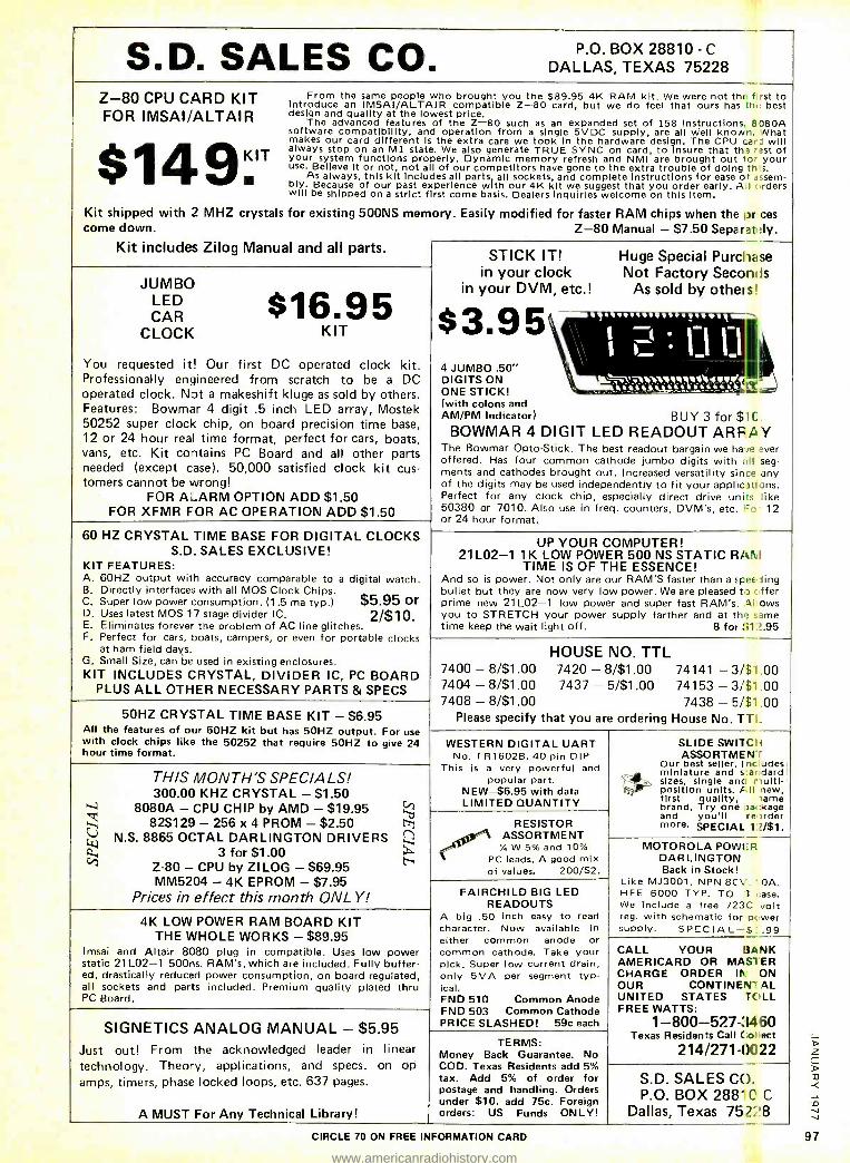
S.D. SALES CO. P.O. BOX 28810 - C
DALLAS, TEXAS 75228
Z -80 CPU CARD KIT FOR IMSAI /ALTAIR
$14911T
From the same people who brought you the $89.95 4K RAM kit. We were not th( : f rst to Introduce an IMSAI / ALTAIR compatible Z -80 card, but we do feel that ours has th, best design and quality at the lowest price.
The advanced features of the Z -80 such as an expanded set of 158 Instructions. E:180A software compatibility, and operation from a single 5VDC supply, are all well known. Nhat makes our card different Is the extra care we took in the hardware design. The CPU cap J will always stop on an M1 state. We also generate TRUE SYNC on card, to Insure that tha .ast of your system functions properly. Dynamic memory refresh and NMI are brought out lor your use. Believe it or not, not all of our competitors have gone to the extra trouble of doing tr s.
As always, this kit includes all parts, all sockets, and complete instructions for ease of . Ssem- bly. Because of our past experience with our 4K kit we suggest that you order early. A I eders will be shipped on a strict first come basis. Dealers inquiries welcome on this Item.
Kit shipped with 2 MHZ crystals for existing 500NS memory. Easily modified for faster RAM chips when the nr ces come down.
Kit includes Zilog Manual and all parts. Z -80 Manual - $7.50 Separat tly.
JUMBO LED CAR
CLOCK $16.95
KIT
You requested it! Our first DC operated clock kit. Professionally engineered from scratch to be a DC operated clock. Not a makeshift kluge as sold by others. Features: Bowmar 4 digit .5 inch LED array, Mostek 50252 super clock chip, on board precision time base, 12 or 24 hour real time format, perfect for cars, boats, vans, etc. Kit contains PC Board and all other parts needed (except case). 50,000 satisfied clock kit cus- tomers cannot be wrong!
FOR ALARM OPTION ADD $1.50 FOR XFMR FOR AC OPERATION ADD $1.50
60 HZ CRYSTAL TIME BASE FOR DIGITAL CLOCKS S.D. SALES EXCLUSIVE!
KIT FEATURES: A. 60HZ output with accuracy comparable to a digital watch. B. Directly interfaces with all MOS Clock Chips. C. Super low power consumption. (1 .5 ma typ.) $5.95 or D. Uses latest MOS 17 stage divider IC. 2$10. E. Eliminates forever the problem of AC line glitches. F. Perfect for cars, boats, campers, or even for portable clocks
at ham field days. G. Small Size, can be used in existing enclosures. KIT INCLUDES CRYSTAL, DIVIDER IC, PC BOARD
PLUS ALL OTHER NECESSARY PARTS & SPECS
STICK IT! in your clock
in your DVM, etc.!
$3.95 4 JUMBO .50" DIGITS ON ONE STICK! (with colons and AM /PM Indicator) BUY 3 for $1(
BOWMAR 4 DIGIT LED READOUT ARFAY The Bowmar Opto- Stick. The best readout bargain we ha ie ,,ver offered. Has four common cathode jumbo digits with all seg- ments and cathodes brought out. Increased versatility since any of the digits may be used independently to fit your applications. Perfect for any clock chip, especially direct drive units ike 50380 or 7010. Also use in freq. counters, DVM's, etc. Fo 12 or 24 hour format.
Huge Special Purchase Not Factory Seconds
As sold by others'
. 1' if.I Y .._..ZA s
UP YOUR COMPUTER! 21 L02 -1 1K LOW POWER 500 NS STATIC RANI
TIME IS OF THE ESSENCE! And so is power. Not only are our RAM'S faster than a spee .; ing bullet but they are now very low power. We are pleased t r
fifer prime new 21 L02 -1 low power and super fast RAM's Al :)ws you to STRETCH your power supply farther and at th a ime time keep the wait light off. 8 for III ?.95
50HZ CRYSTAL TIME BASE KIT - $6.95 All the features of our 60HZ kit but has 50HZ output. For use with clock chips like the 50252 that require 50HZ to give 24 hour time format.
HOUSE NO. TTL 7400 - 8/$1.00 7420 -8/$1.00 74141 - 3/$1 00 7404 - 8/$1.00 7437 - 5/$1.00 74153 - 3/$1 .00 7408 - 8/$1.00 7438 -5 /$1 .00
Please specify that you are ordering House No. TTI_
W
THIS MONTH'S SPECIALS! 300.00 KHZ CRYSTAL - $1.50
8080A - CPU CHIP by AMD - $19.95 825129 - 256 x 4 PROM - $2.50
N.S. 8865 OCTAL DARLINGTON DRIVERS 3 for $1.00
Z -80 - CPU by ZI LOG - $69.95 MM5204 - 4K EPROM - $7.95
Prices in effect this month ONLY!
'b t-=-1
ti
WESTERN DIGITAL UART No. TR1602B. 40 pin DIP
This is a very powerful and popular part.
NEW -$6.95 with data LIMITED QUANTITY
RESISTOR ASSORTMENT
Y. W 5% and 10% PC leads. A good mix of values. 200/$2.
SLIDE SWITCH ASSORTMEN r
Our best seller. I ne Jdes miniature and s:& dard sizes, single anc r nulti- position units. F. II new, first quality, name brand. Try one pa .Kage and you'll re nrder more. SPECIAL 12/$1.
4K LOW POWER RAM BOARD KIT THE WHOLE WORKS - $89.95
Imsai and Altair 8080 plug in compatible. Uses low power static 21 L02 -1 500ns. RAM's, which are included. Fully buffer- ed, drastically reduced power consumption, on board regulated, all sockets and parts included. Premium quality plated thru PC Board.
SIGNETICS ANALOG MANUAL - $5.95 Just out! From the acknowledged leader in linear technology. Theory, applications, and specs. on op amps, timers, phase locked loops, etc. 637 pages.
FAIRCHILD BIG LED READOUTS
A big .50 inch easy to read character. Now available in either common anode or common cathode. Take your pick. Super low current drain, only 5MA per segment typ- ical. FND 510 Common Anode FND 503 Common Cathode PRICE SLASHED! 59c each
MOTOROLA POWER DARLINGTON Back in Stock!
Like MJ3001 . NPN 8C', . OA. HFE 6000 TYP. TO -.3 ase. We include a free 723C volt reg. with schematic for p, giver supply. SPECIAL -$ .99
TERMS: Money Back Guarantee. No COD. Texas Residents add 5% tax. Add 5% of order for postage and handling. Orders under $10. add 75c. Foreign
A MUST For Any Technical Library! orders: US Funds ONLY!
CALL YOUR BANK AMERICARD OR MAS1ER CHARGE ORDER III ON OUR CONTINEVII AL UNITED STATES TOLL FREE WATTS:
1- 800 -527 -3460 Texas Residents Call Col ect
214/271 -0C122
S.D. SALES CO. P.O. BOX 2881( C
Dallas, Texas 752!8 CIRCLE 70 ON FREE INFORMATION CARD 97
www.americanradiohistory.com
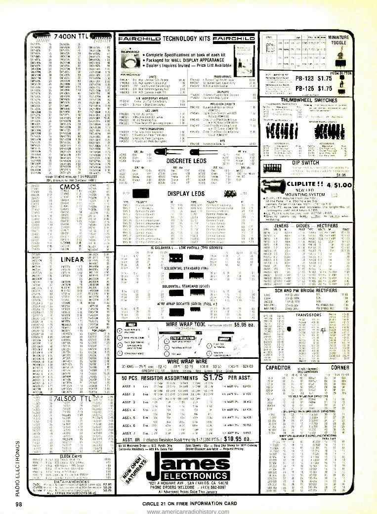
98
P*mmr7400NTTL lr
SN7400N 16 SN74594 25
SN74015 1E SN7460N 22 SN74154N SN7402N 21 SN74705 45 SN74155N SN7403N 16 SN74725 39 SN74156N SN7404N 19 SN74735 37 SN74157N SN7405N 24 SN74745 32 SN74160N SN7406N 20 SN7475N 50 5574161N SN7407N 29 SN7476N .32 SN74163N SN7408N 25 SN74795 5 00 SN741645 SN74095 25 SN7480N 50 SN74165N SN7410N 18 SN7482N .98 SN74166N SN74115 30 SN7403N 70 SN74167N SN7412N 33 SN7485N 89 5574170N SN7413N 45 SN7486N 39 S5741725 SN74145 70 SN7488N 3.50 SN74173N SN74165 35 SN7489N 2 49 SN74174N
SN7417N 35 SN7490N 45 S5741755 SN7420N 21 SN7491N 75 SN74176N
SN74215 .33 SN7492N d9 S5741775 S574225 49 SN7493N 49 5574180N SN7423N 37 SN7494N 79 SN74181N
SN7425N 29 SN7495N 79 SN74182N S574265 29 SN7496N .89 SN74184N
SN7427N 37 SN7497N 4.00 SN741855 SN7429N 42 SN74100N 1 00 5574186N SN7430N 26 SN74107N .39 SN74187N SN7432N 31 SN74121N .39 S5741885 7574375 27 61,1741229 39 05741906 SN7438N 27 SN741236 50 65741919 SN7439N .25 51,1741259 ,60 511741929 SN7440N 15 59741265 .60 59741939 5974415 89 69741329 1.09 59741949 SN7442N 59 SN74136N 95 69741956 5974436 75 99741419 1 15 S5741965 SN74445 75 S5741425 4.00 59741979 SN7445N 75 SN741439 4.50 SN74198N 91,174469 81 65741449 4 50 69741995 51,174479 69 56741459 1 15 69742009 9174485 79 SN74147N 2.35 SN74279N SN7450N 26 09741489 2 00 59742519 5674516 27 09741509 1.00 69742949 5874535 27 09741516 79 69742855 SN74549 20 58741539 89 68743679
MANY OTHERS AVAILABLE ON REQUEST
20% Discourt tor 100 Combined 7400's
1 00
99
99
99
1 25
99
99
1 10
1 10
1 25
5 50
2 10
895 1 50
1.25
90 90
99
2 49
95 195
2.20 1500
6 00
3.95 1.19 1 25
89
89
1 25
75
1 25 75
1 75
1 75
5 59
90 1 79
6.00 6 00
75
FAIF2cHIL_D TECHNOLOGY KITS FAIF2CHIL_D
1 t L Hh4IL0G1 Complete Specifications on back of each kit
Packaged for WALL DISPLAY APPEARANCE
Dealer's Inquires Invited - Price List Available
DIGITS - 0'J00'í C 5. ign Common Cathode 01911
0,90002 0 5 59f Common Anode DIg11
1700003 357 9191 Common Cathode 2191
1765004 0 8 High Common Cathode 019,1
1700005 0.8 High Common Anode 0191
51.00 1 00
75
2 00
200
PHOTO ARRAYS
17190040 9- Element Tape Reader Array 1760041 12- Element Card Reader Array
F703042 Relleclxe Oplo Coupler
16 00
24 DO
4 Do
0.8" HIGH DISPLAY ARRAYS
1790010 12 Hour 3'2 Digit Gluck Display 9710011 24 Hour. 4 Digit Clock Display
7 00
8.00
COUPLERS F710050 3 General Purpose Opta Couplers
F780051 Darlington Opld Coupler
I DO
I 00
Arr 24. MINIATURE ON OFF 27, 2 95 55 1 87 1 s TOGGLE
ON NCAIF 723 2 95 2 15
0 7 35 $.55 I.
ON M5NE ON 05 165 1 71 1'0 I t" P1E9 PUSN BUTTON
PB-123 $1.75
PB-126 $1.75 ima
LEI) LAMPS
17110020 10 Red LED Lamps FTK0021 5 Mixed Colored LED Lamps
1700022 10 LEO Mounting Clips FT60023 5 Three Piece LEO Mounlmg Adapters
100 100 1 00
1 00
PHOTO TRANSISTORS 17110030 5 Flat Lens Photo Transistors F100031 5 Round Lens Photo Transistors
1760032 3 Flat LOIS Photo 091119lons 1760033 3 Round Lens Photo Darlingtons
1 00 1 00
00 1 0
17K0400
FTK0401
17K0402
FTK0403
17110405
MOS CLOCK CIRCUITS
219101 Cock'Caleldar Cano 905370011
DIg1a1 Clock Calendar wilt BCD
Outputs 1FCM70021
Direct Oreste 0191191 Clog Cecu11
w'in AC output rFCM3817A1
Direct 011ye Diva, Clock Circu't wnh DC Output IFCM3817D,
Oued Dlwe DIgltal Clock Calendar
Cucul IFCM70151
7 00
7 00
s DO
5 00
6 00
KITS
FTK0106 Automolle Clock 911 40 00
004000 C 04001 024002 CD4006 004007 C04009 004010 004011 C74012 004013 24518
03401' íD4019 -4020 07:022 0:)4027 403
504025 C0402" 504029 r040s_ ,:04010
25
50
05 59
59 25
25
,16 55
1 49
0
05
69
2w 55
CD4035 CMOS
1 85
CD4040 2 45
004042 190
004044 1 50
CD4036 2 51
[D4047 2 75
CD4049 79
CD4050 79
CD4051 2 95
004053 3 95
CD4060 3 25
CD4O66 i 'S CD4069 5
CD4O71 45
CD40B1 45
CD451! 2 50
C04518 2 50
CD4566 3.00 74000N 74CO2N
74C04N
740105 74C20N
74030N
74425 74C73N
74C74 7409011
740955 74C107N 74C151
740154
740157 74C160 740161 140153
',0161 740173 740193 740195
39 Mca04- MC14016 55
75
65
65 65
2 15
150 1 is
3 DO
2 DO
1 25
2 9(i
4 00
2 15
3 25
3 25
3 OC'
3 2"
2 60
2 ':' 275 4 50
56
XC209
XC209
XC209
4C22
XC22
422 XC22
55L 22
D1 707
TYPE
'Á0N MA N 2
',IAN 52
MAN 64
AN 72
MAN 74
', N P.
125" dia. Red 10'51 KC 111
Green 4.S1 +C 111
Orange 451 DISCRETE LEDS 0111 xGll
.200" dia .18s'' dia. zoo'' dia. Red "'. St 8C526 Red 10 /51 107 10 SI
Green XC526 Green 4/61 'Ci 7 51
yellow XC526 Yellow 4;51 00556 Veilow 1'51 5' Orangr SI X0522 Fange 4/51 919 D'ange 751 RT
- ar 4/51 ' .Iear 7 SI
1.11 DISPLAY LEDS
POLARITY
Common Moue 5.89 Dot Matm Common Cathode Common Cass to Common Anode
Comon Anode green Common Anote- yellow
Onlmon Anode -green Common Anne.'en Commo^ Anone Common Galndae I moron Anode yellow
HT
300 125
187
300
300 300 Soo
400 100
200
1.5
95
39
IS 95
75
75
5'C
TrFL POLARITY
0i7G1
DL 704
DL70: Dl 726
DL :4- Oc :50 DI 319
INDIC 190501 N05u"
.range
Anode -tea
common Ca1101e
Commonnode C
09,mor Anode Commun Cathode
Cnonnern Cnnon1 004 "' Ca1118110
Common Callot( Common node
90" dia Red 10151
Green 4'51
5.840* 51
Orange 4:51
085" dia. MV50
085 dia Micro 'ed LED
6-SI
53339
HT
300 1 75
300 ' 75
300 t 95
300 ...
300
300
50C
6óó z i ID 50
255 500 I 00
500 1 00
THUMBWHEEL SWITCHES
[ 1' swaw.,pW^cHpx °n.a'+rcw..ewo'mro..M'
as I0P1rFOnecOa°1r .
21
°)es,
SF EP
SF OF
SF fee
SERIES SR MA Avina AuarnAv
Daseriptkon
IsmO Elne; each, 40
Nu ACCESSORIES
^mw o.r. 5P EA5 PIAFS 5 5d
DIP SWITCH
S1 95
CLIPLITE !I 4 $1.00 NEW LED
MOUNTING SYSTEM CLIPLITE 4110 is tram the front of the Panel in a .250 hole on 3/8" centers. Panel thickness from 1/16" to 1 /8. CLI!PLITE equalizes and ingreases the brightness of commonly used wide beam LEDS.
CLIPLITE is so be used with XC556 LEDS. Specify colors -tad, green, amber, or yellow when ordering.
.M300H 163011
80
35
35 75
1 00 95
LINEAR LM370N LM373N
35 1M3779 1 00 LM380N 100
1 10
99
N 1 15
90
52
112 15
18
' 24
M ,IN LM340K5 LM340K-6 LM340K 8
1M3400-12 1.63401( 15 LM3406-IB LM340624 lM3aOT-5 1M3407-6 LM340T,8 LM340T/12 LM340T-15
!í.1O718 11 405-24
LM3B1N 1.613825 NE501K
NE510A 90 NE531N
50 NE5361
30 NE5a0l
35 NE550N
35 NE555V
35 NE560B
35 NE561B
75 NE5628
75 NE565H
75 NF565N
75 NE566CN
75 NE567H
75 NE567V
75 1M703CN
95 LM709H
80 LM709N
70 LM710N
95 1.07115
95 LM723H
95 LM723H
95 LM733N
95 LM739N 95 LM741CH
95 LM741CN
75 LM74114N
75 LM747H 75 0M7479
75 LM740H
75 1M74811
75 LM13D3N
75 LM1304N
W LM1305N 55 eM130'N
LM1310N 2 95
LM13515 1 55
1M14149 1 75
LM 1458C 65
115 LM1496N 95
25 1.515569 1 85
00 LM211161 1 95
39 LM29015 2 95
05 LM3065N 69
79 LM3900N 55
79 LM39O5N 60
00 LM3909 1 25
00 LM5556N 1.85
00 MCS558V 1.00
00 LM7525N 90
00 LM7535N 1 25
79 8028B 4 95
1575450 49
5.00 75451CN 39
5 00 75452CN 39
600 75453CN 39
1 25 754.5409 39
1 75 75491CN 79
1.25 75492CN 89
1 95 7549409 89
1 50 RCA LINEA
45 CA3013
29 CAJ032
29 CA1035
79 CA3039
39 CA3046
55 00.3059 55 CA3060
100 CA3080 100 CA3081
35 CA30B2
35 CA3093
39 CA3086
79 CA3089
79 CA3091 1
39 CA3123
39 CA3130 90 CA3140
1 19 CA3600 1 40 RC4194
85 RCa195
15
56
48
35
30
25
25
85
00 00
60
65 75
20
15
39 25
75
95
25
Jon
6 pin
5 17
20
22
18 pin 29
22 Din 37
2'n 527 30
p1n 35 4 pin 49
p'n S30 35 36
52
pm 5 45
211 39
b pm 43
'8 oln 75
IC SOLDERTAIL - LOW PROFILE (TIN) SOCKETS
50.107 ' -24 illat p, ,B Boi^ 5
60 53
20 36 p'n
26 ° 40 mn
36 35 SOLDERTAIL STANDARD (TIN)
25
30
4,2
41
'8
58
_ MI 2B o.
36 on 40 Din
SOLDERTAIL STANDARD (GOLD)
Nom 24 pin 2B Dn afi p
4C c
WIRE WRAP SOCKETS (GOLO) LEVEL a3 37
37
41
fit 11111 "le
2549 50-'30 37 35
44 43
59 5P
62 6
S 99 90 81
1 39 1 26 I 15
159 145 130
S 70 63 57 1 10 1 00 90 1 75 1 40 26
75 159 145
i' 05 95 ' 40 1 25
159 1 AS
i7_ 5=
85 10
' 30
n
ZENERS - DIODES - RECTIFIERS TYPE VOLTS W PRICE TYPE VOLTS W PRICE
1N746 3 3 4001.4-. 4 1 00 194005 600 Ph 1 AMP 10 100 140514 5 1 400m 4 1 00 1144005 800 Pn'1 AMP 10 ' 00
'9:52 5 6 uOOm 1 00 '94007 '000 PIA 1 AMP 10 1 OG
'N753 62 400m' .100 1,3600 50 20019 6100 15754 68 40051 41 DO '193'49 '5 10m 15 00 15959 82 40015 8' 00 1194153 35 10m 12 t 00
199656 15 4000^ - ' 00 íN4305 75 2571 20 1 00 155232 56 500m 28 113534 56 Ire 28
'95234 6 2 500m 28 150135 6 2 to 28
155235 68 50011. 28 1193736 58 tw 28
155235 7 5 500m 2h '94738 8 I IN 28
19456 25 4051 6 ' 00 154742 12 1ve 28
19451 150 9rn I ' 00 054744 15 1w 20
154650 180 10n' 6 1 00 191183 50 PIA 35 AMP 1 60 1144001 50 PIV 1 OMS 12 1 00 151184 103 PN 35 AMP 1 70
194002 100 P75 1 AMP I2 100 191185 150 PIV 35 AMP 150 194003 200 19 I AFAP 02 100 '551286 200 05 35 AMP 1 80 1N4004 400 ..V i AMP 12 1 00 1191180 400 PIN 35 AMP 100
SCR AND FW BRIDGE RECTIFIERS 0360 154 @ 4005 SCR SI 95
038M 354 @ 2005 SCR 1 95
252328 1 SA @ 2005 SCR 50
MOR 9801 254 @ 505 FW BRIDGE REC ' 95
MOA 980-3 254@ 1000 FW BRIDGE RE' ' 95
WIRE WRAP TOOL P8nN,lm6e,052 30 $5.95 ea.
/ Fiui® yi I 0 rxNeiMlel APeaOr
o (1 root 0 NaddwKlK,l51d1 O d.Irk.IKal
0 91. wIH ° O 44961Mnp4aM"r
WIRE WRAP WIRE 30 AWG - 25 ft. min. - 52.10 50 tt. - $2,75 100 11. - 53.50 1000 ft, - $24 00
SPECIFY C01 OR - White - YPllow - Red - Green - Blue - Black
Mó5805 55' W M S 556 51 00
.529064 4 5' OC
t,7907A 5 S UL 2925 55' OG
-.11155 5 el
TRANSISTORS ói
219:'
-..6O.P 2N5412
'41013 '43513 )4LS20 '40925 -41517
39
219 39 49
45 49
39 45 49
39
74LS00 TTL'dL5139
AISES 74L586
741590 741592 741593 741595 741596
.'435107 74 L5109 :415'12 7405132
39 7415136 65 7413138
65 2 19
2.49 65
1 25
125 t 25 7 19
' 89 65
.65 65
155 65
89
1.95 155 1 89 1 55
7415'62 2 25 7415163 225 1505164 2 25 7415175 1.95 1Á15'81 3 69 743S190 2 85 7415191 2.85 7415192 2 65 7415193 2 85 7435194 2 25 7415195 2 25 7715257 1 89 741.5260 55
7435279 79
7435670 5 95
CLOCK CHIPS 6 DigO BCD 0410116 Reset PIN.
6 Dig, BCD 0410010 12 or 24 Hour 4 0911. BCD Outpu11 1 PPS Nang 6 13'911 10 or 24 554' 50 01 60 11
m 1 PRA 001091
12 or 24 Hou'
59 95 4 95 4 95 4 95
6 95
9 95
5 95
50 PCS. RESISTOR ASSORTMENTS $1.75 10 OHM 12 OHM 15 OHM 18 OHM 22 357.1
ASST. 1 5 ea 27 OHM 33 OHM 39 OHM 47 OHM 56 OHM 50 PCS.
68 OHM 82 OHM 100 OHM 120 OHM 150 OHM
ASST. 2 5 ea 180 OHM 220 OHM 270 OHM 330 OHM 390 OHM 50 PCS.
470 OHM 560 OHM 580 OHM 820 OHM 0 ASST. 3 5 ea i 2K 1 50 1 BK 2 211 2'0 50 PCS
33K 39K 47K 5 S 669 ASST. 4 5 ea 6 211 100 100 15K ISO 50 PCS,
220 270 330 399 411,
ASST. 5 5 ea 56K 880 82K 1005 120K 1l4 WATT 5^. SO PCS.
1500 1800 220K 270, 3300
ASST. 6 5 ea. 3906 4709 5600 680, 8205 14 WATT 5% 50 PCS.
1R 1 2M 1 5M 1 8M 2 2M
ASST. 7 5 ea. 2 1M 3 3M 3 9M 4 7M 5 6M 1/4 WATT 5 °° 50 PCS.
ASST. BR Includes Resistor Assortments] -7 (350 PCS.) $10.95 ea.
PER ASST.
1i4 WATT 5%
1/4 WATT 5 °.
1/4 WATT 5%
1/d WATT 5%
DATA HANDBOOKS 7400 P... 011 15400'7400 ICS $2.95 CMOS Pm 001 a' :+ r,nr1 01 4000 Serles ICS 52.95 Linear Pin out 5 1 .rid, Desnr1210100 52.95
ALL THREE HANDBOOKS 56.95
55.00 Minimum Order - U.S. Funds Only Spec Sheets - Ose - Send 24v Stamp for 1977 Catalog
Californie Residents - Add 5% Sales Tao Dealer Discount AYellable - Request PrltIng
J ames ELECTRONICS
1021 -A HOWARD AVE.. SAN CARLOS. CA. 94070 PHONE ORDERS WELCOME - (415) 592 -8097
All Advertised Prices Good Thru January
CAPACITOR SO VOLT CERAMIC
DISC CAPACITORS 19 10.49 50.100 19
10 pl 05 04 03 .001µF 05
22 pl 05 04 03 .0047µF 05 04
47 pl 05 04 03 01k2 05 04
100 pi 05 04 03 0221F 06 05
220 pl 05 04 03 0471E 06 05
470 pl 05 04 035 I1F 12 09
100 VOLT MYLAR FILM CAPACITORS
001mí 12 10 07 022m1 13 it OR
0022 12 10 07 041111 21 17 13
0047mí 12 IO 07 1511 27 23 17
01111 12 IO 07 22mí 33 .27 22
020% DIPPED TANTALUMS SOLIDI CAPACITORS
1'355 28 23 17 1 5,355 30 26 21
15.355 28 23 17 2 2/25V 31 27 22
2235V 28 23 17 3 3255 31 27 22
33 35V 28 23 17 4 7 255 32 28 23
47 355 28 23 17 6.8/250 36 31 25
68 35V 28 23 17 10 25V 40 35 29
10:355 29 23 17 15255 63 50 40
MINIATURE ALUMINUM ELECTROLYTIC CAPACITORS
Allal Leed Radial Leed 47.605 15 13 10 47.255 15 13 10
1 0 50V 16 14 11 47505 16 14 11
3 3505 1 5 13 I O 1.Oí 165 15 13 10
4 7/255 16 14 12 1 01255 15 14 it 10.255 15 13 10 1 0'500 16 14 11
10605 16 14 12 4 7 /16V 15 13 10
22.259 17 15 12 4 7'255 15 13 10
22,505 24 20 18 4 7/500 16 14 11
47255 19 17 15 10/16V 14 12 09
47.50V 25 21 19 10 /25V 15 13 10
100.255 24 20 18 10605 16 14 12
100 50V 35 30 28 47'50V 24 21 19
220 25V 32 28 25 100 /15V 19 15 14
210'505 45 41 38 100/255 24 20 18
470 25V 33 29 27 100/50V 35 30 28
1000.161/ 55 50 45 220/165 23 17 16
2200 165 70 62 55 470/255 31 28 26
CORNER
149 50,100 035 035 035 04
04
075
CIRCLE 21 ON FREE INFORMATION CARD
www.americanradiohistory.com
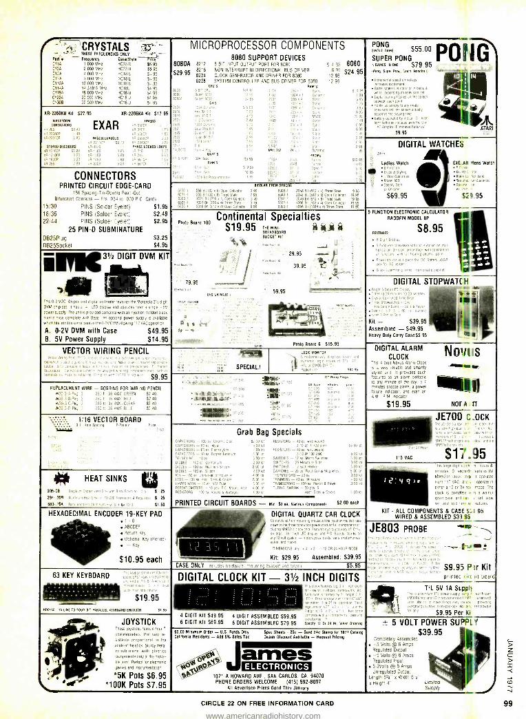
(- -,,i' CRYSTALS Yi,),, _ '- THESE FREQUENCIES ONLY L= _v }--
Pedor Frequency Case /Style Price CYIA 1 000 MHz -1C33 U 55.95 CY2A 2 000 MHz HC3311 $5 95 CROA 4.000 MHz -1018 U 54 95 CYFA 5.000 MHz 3018 U 54 95 CY12A 10000 MHz IH018: U 54,95 CY14A 14 31818 MHz HC18U 54 95 C9194 18.000 MHz HC18 U 54 95 09225 20 000 MHz H018U $4 95
29300 32.000 MHz 7018 U $- 95
OR- 22606E Kit $27.95 OR 2206KÁ Kit 517.95
WAVEFORM GENERATORS
e, 205 KR SOOT, OR.:TA -RP
STEREO DECODERS ER 131OCP Sa 20
ER1310ER 320 1800P 3 -0
R 256 2 99
EXAR MISCELLANEOUS
TIMERS
nf,P
PHASELOCKEO LOOPS
CONNECTORS PRINTED CIRCUIT EDGE -CARD
U6 Spac 9c) Tm -0CUni Re. td Out
Bifurcated Contacts - Its 054 to 070 P Card,
MICROPROCESSOR COMPONENTS 8080 SUPPORT DEVICES
8080A
S29.95
8212
8216 8224 8228
8 BIT INPUT OUTPUT PORT FOR BOBO
NON INTERRUPT BI- DIRECTIONAL BUS DRIVER CLOCK GENERATOR AND DRIVER FOR 8080 SYSTEM CONTROLLER AND BUS DRIVER FOR 8080
S 4 95 6 95
1295 12 95
8080 $24.95
SPICS RAM'S S19 95 t 250
'T 1024 r 1 Dyna T,r,
- - LL Pe 256 : 5a SRS 2'D2 '024 %' talc
S 9 00 40,96 , '
S6 =
0:
DART S
RUMS
,10
2
Si 95
S 9 95
10
97421 6
MM5362 2k r 1 Dynamo
PROMS
Je01 256.4
5 95
1 ]5 9 95
6 95
29 95
49
b 95
6 95 E 49
2 25
BIPOLAR PROM SPECIAL
,.n Conetlor 2 95 63061 20413 Bo I" Thee Stile 's 9_
6342 -'I ZOO Bit '. 7pen CL REmr '995 _I, R,or 3 49 604' , 2048 MI - Three State t9 1-
15/30 PINS (Solder Eyelet) $1.95 " 495 00' 0969. 4'I`rñ9 AE i9á=
18/36 PINS (Solder Eyelet) $2.49 22/44 PINS (Solder Eyelet) $2.95
25 PIN -D SUBMINATURE DB25PIug S3.25
DB25Socket $4.95 ¡FIN 31/2 DIGIT DVM KIT
ThIS 0 -2 SOC 05 per cent OIgllal voltmeter features the Motorola 3' E digit DOM chip SHE II has a 4 LED display and operates from a single -5V power supph The unit Is provided complete with an mlectmn molded 09ck plastic casse complete Wlil Bezel An optional power supply Is available
,. ^cl fns TIOm<' sain. -ose 101110 'VOVM allowing 117 VAC opearion
A. 0 -2V DVM with Case S49.95 B. 5V Power Supply $14.95
VECTOR WIRING PENCIL
S9.95
REPLACEMENT WIRE - BOBBINS FOR WIRING PENCIL
$2 4O
52 40 .. .. - S2 :O
1/16 VECTOR BOARD r lamino PPaII¢rr
0 HEAT SINKS
205 CB
291.368 ;...
680- .758 e.,:...
S 25
E 25
S7.60
HEXADECIMAL ENCODER 19 -KEY PAD 1 -0
ABCDEF
. Return Key
Optional Key (Period) - Key
$10.95 each
PONG SINGLE GAME
4 GAMES IN ONE 579.95 IPon9. Super Pang. Catch. Handball
S55.00 POIIIG SUPER PON G
speed on wheys increase- e.rnement Game m m bale ö
white aepener set
QOValarormquasneá between each point
Hooks up simply In nrly -'a television set the
becomes the CiaYing
Battery opera d by 4 ske 0 tla5n
9'1C Epacta, I E m a nares Batter
enI
$9.95
DIGITAL WATCHES
e Ladies Watch 6 F
Bracelet Styinge
n
1 Year Guarantee
Mode 900
Spec he
omr
S69.95
I ATARI
EXEAR Mens Watch
0... m rl
ala H her Bane Ite EE Ir Gulrtn
$2 I.95
Proto Board 100 Continental
Specialtiesy( yL $1995 BREADBOARD MUNI + '* BUDGET KIT
DESIG N MATE I
59.95
29.95 -.--
39.95 I._
Prolo Board 6 $15.95
SPECIAL!
LOGIC MONITOR
r
SEE 95
)111.11MFSt 'IN iIi'2
IIIIWdT.' o
Grab Bag Specials
oT Prolo SHOO
-.rt...- 60 ..
52001n1 RES SOULS Lb eL :^1
0010; 555010'. 400Td s1oR5 - tr h . .
400 5DDIDI 00 11 TCHES - . nes '_ 00 lot
200ot !0olot 2 0O ot SV.o1CHE5 - i2 ae^ Rece> 1 001o1
2 GO mt 5W TCHES - 20 ea RreuCOn S Magnehrs 5 Do ol.
DO rot THERMISTORS-20ea 300io1 5 00 mt TRIMMERS - 4D ea Mmlature I 00 or 3 00 lot TRANSISTORS - 100 ea Plasnc A POOH ! 00 I 4 OG at TUBING SHRINK - 30 pcs 6
n wst 51es ö Credo
PRINTED CIRCUIT BOARDS - Mtn 50 ea various Components $2.00 each
DIGITAL QUARTZ CAR CLOCK eoli. rer.o
caver core and all components in .. q Features quartz accuracy of Dl', T :lay. AIE Boards Works o' O'cycles coals vans, motorhomes
63 KEY KEYBOARD
$19.95 HOWES 16 LINE TO FOUR BIT PARALLEL KEYBOARD ENCODER 51.95
JOYSTICK Theca joysticks !WRIT tour
noteyhometers. that vary re-
slstaTce proportional to the
angle of the stick Sturdy metal
construction with plastics components only at the mova-
ble Inlnt. Perfect for electronic
games and Instrumentation
*5K Pots $6.95 9100K Pots $7.95
Kit: $29.95 CASE ONLY Io- Ses hardware mounting Oackrt
Assembled: S39.95
S5.95
5 FUNCTION ELECTRONIC PAl rill ATOR
FEATURES
$8.95RADOFIN MODEL 8P
or
DIGITAL STOPWAT( H
ed
e stopwatches.
e Evert ,2ts , 90 r.
Penne Rene_
Kit - $39.95 Assembled - $49.95 Heavy Duty Carry Case $5 95
DIGITAL ALARM
CLOCK Tins 4 digit Novus Alarm Clock
a very reliable and smartly styled unit. II provides such features as an alarm settable to any minute of he day, a 7
minutes snooze alarm, a power Iarure Indicator and even an
a M R M ndicator
Novi 's `Ww Uew
IMO $19.95 NM' A IIIT
115 VAC
JE700 COCK
$11..95 e lis large mg rc., ì TOUES
mutes 3 sec Ind eatures Me
MM5314 clac: '.h p I operates
from 117 VAC EIC Operate Ir.
enner a 12 or Os has mode The
c10Ck IS compee M '1 a walnut grain CaSe ao.t I as :t set slow
s =t and hold rte s= 'eatnres
KIT - ALL COMPONENTS & CASE S:1.95 WIRED & ASSEMBLED $33.95
JE803 PROBE 111+
# s
$9.95 P Kit
DIGITAL CLOCK KIT - 31/2 INCH DIGITS p11t11ec I I 1
4 DIGIT KIT 549.95 4 DIGIT ASSEMBLED 559.95 6 DIGIT KIT 569.95 6 DIGIT ASSEMBLED 579.95 sp., m r, 01'24 HE When Ordering
55.00 Minimum Order - U.S. Funds Only Spec Sheets - 25c - Send 24c Stamp for 1977 Catalog California Residents - Add 6% Sales Tan Dealer Discount Available - Request Pricing
ames ELECTRONICS
1021 -A HOWARD AVE.. SAN CARLOS. CA. 94070 PHONE ORDERS WELCOME - (415( 592 -8097
All Advertised Prices Good Thru January
CIRCLE 22 ON FREE INFORMATION CARD
TEL 5V 1A Stupolr
$9.95 Per Ki
5 VOLT POWER SUPPLY $39.95
Completely Assembled -5 Volts @ 6 Amps Regulated Output
5 Volts @ 6 Amps Regulated Input 6.3VOlts @ 5 Amps Unregulated Output
Length 8Ve" K Width 611` x Height 4'' Limited
Supply
99
www.americanradiohistory.com
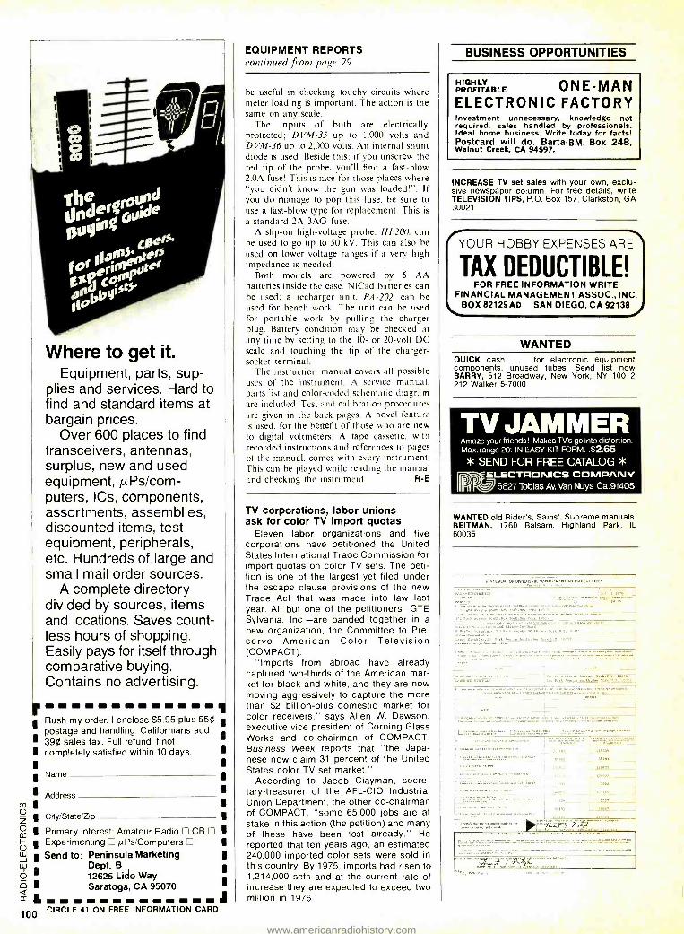
Where to get it. Equipment, parts, sup-
plies and services. Hard to find and standard items at bargain prices.
Over 600 places to find transceivers, antennas, surplus, new and used equipment, µPs /com- puters, ICs, components, assortments, assemblies, discounted items, test equipment, peripherals, etc. Hundreds of large and small mail order sources.
A complete directory divided by sources, items and locations. Saves count- less hours of shopping. Easily pays for itself through comparative buying. Contains no advertising.
r I Rush my order. I enclose $5.95 plus 550 I postage and handling. Californians add
1 390 sales tax. Full refund if not 1 completely satisfied within 10 days. I I I I Name I I Address 1 1 1
I O!ty /State /Zip 1
1 Primary interest: Amateur Radio CB I 1 Experimenting µPs /Computers 1
1 Send to: Peninsula Marketing I Dept. B I 12625 Lido Way
1 Saratoga, CA 95070
L J CIRCLE 41 ON FREE INFORMATION CARD
EQUIPMENT REPORTS continued from page 29
be useful in checking touchy circuits where meter loading is important. The action is the same on any scale.
The inputs of both are electrically protected; DVM -35 up to 1,000 volts and DVM -36 up to 2,000 volts. An internal shunt diode is used. Beside this: if you unscrew the red tip of the probe, you'll find a fast -blow 2.0A fuse! This is nice for those places where "you didn't know the gun was loaded! ". If you do manage to pop this fuse. be sure to use a fast -blow type for replacement. This is
a standard 2A 3AG fuse. A slip -on high -voltage probe, HP200, can
be used to go up to 50 kV. This can also be
used on lower voltage ranges if a very high impedance is needed.
Both models are powered by 6 AA batteries inside the case. NiCad batteries can be used; a recharger unit. PA -202. can be used for bench work. The unit can be used for portable work by pulling the charger plug. Battery condition may be checked at any time by setting to the 10- or 20 -volt DC scale and touching the tip of the charger - socket terminal.
The instruction manual covers all possible uses of the instrument. A service manual, parts list and color -coded schematic diagram are included. Test and calibration procedures are given in the back pages. A novel feature is used, for the benefit of those who are new to digital voltmeters. A tape cassette. with recorded instructions and references to pages of the manual, comes with every instrument. This can be played while reading the manual and checking the instrument. R -E
TV corporations, labor unions ask for color TV import quotas
Eleven labor organizations and five corporations have petitioned the United States International Trade Commission for import quotas on color TV sets. The peti- tion is one of the largest yet filed under the escape clause provisions of the new Trade Act that was made into law last year. All but one of the petitioners -GTE Sylvania, Inc. -are banded together in a new organization, the Committee to Pre- serve American Color Television (COMPACT).
"Imports from abroad have already captured two -thirds of the American mar- ket for black- and -white, and they are now moving aggressively to capture the more than $2 billion -plus domestic market for color receivers," says Allen W. Dawson, executive vice president of Corning Glass Works and co- chairman of COMPACT. Business Week reports that "the Japa- nese now claim 31 percent of the United States color TV set market."
According to Jacob Clayman, secre- tary- treasurer of the AFL -CIO Industrial Union Department, the other co- chairman of COMPACT, "some 65,000 jobs are at stake in this action (the petition) and many of these have been lost already." He reported that ten years ago, an estimated 240,000 imported color sets were sold in this country. By 1975, imports had risen to 1,214,000 sets and at the current rate of increase they are expected to exceed two million in 1976.
BUSINESS OPPORTUNITIES
HIGHLY ONE -MAN PROFITABLE
ELECTRONIC FACTORY Investment unnecessary, knowledge not required, sales handled by professionals. Ideal home business. Write today for facts! Postcard will do. Barta -BM, Box 248, Walnut Creek, CA 94597.
INCREASE TV set sales with your own, exclu- sive newspaper column. For free details, write TELEVISION TIPS, P.O. Box 157, Clarkston, GA 30021
YOUR HOBBY EXPENSES ARE
TAX DEDUCTIBLE! FOR FREE INFORMATION WRITE
FINANCIAL MANAGEMENT ASSOC., INC. BOX 82129AD SAN DIEGO, CA 92138
WANTED QUICK cash . . for electronic equipment, components, unused tubes. Send list now! BARRY, 512 Broadway, New York, NY 10012, 212 Walker 5 -7000
TV JAMMER Amaze your friends! Makes TV's go into distortion. Max. range 20'. IN EASY KIT FORM $2.65 * SEND FOR FREE CATALOG *
ELECTRONICS COMPANY 6827 Tobias Av. Van Nuys Ca.91405
WANTED old Rider's, Sams', Supreme manuals. BEITMAN, 1760 Balsam, Highland Park, IL 60035
STATEMENT OF OWNER D CIRCULATION
:.....,. .,
e ............. ,,,
www.americanradiohistory.com
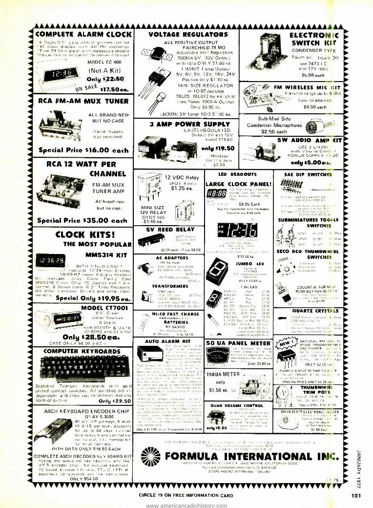
COMPLETE ALARM CLOCK '4 Digits 0.5" LED with brightness control '12 Hour display with AM /PM indication 'True 24 hour alarm with repeatable snooze -Power failure indication for power interrupt
MODEL EC 400
(Not A Kit) Only 42350_
ON SA-E S17.5Oea.
VOLTAGE REGULATORS ALL POSITIVE OUTPUT
FAIRCHILD 78 MG Adjustable Volt Regulators 500MA 5V 30V Output with data ONLY $1.60 ea.
LM34OT 1 amp Output 5V, 6V, 9V, 12V, 15V, 24V
Positive only $1.10 ea.
MINI SIZE REGULATOR in TO -92 package
78L05, 78L012 by Fairchild Low Power 100MA Output
Only $0.80 ea.
LM309K 5V lamp TO -3 $1.00 ea.
RCA FM -AM MUX TUNER
ALL BRAND NEW BUT NO CASE
(Power Supply Not Included)
A,
ELECTRONIC SWITCH IIIT CONDENSER TYI E
Touch on TOJ(:h 3ff use 7473 I.C.
and 12V relay
$5.50 each
FM WIRELESS MIC FUT Transmit range up to E Oft
Easy to asserrbl
$4.50 each
3 AMP POWER SUPPLY UA723 REGULATED
Output 5V and 12V Input 110AC
Special Price $16.00 each
RCA 12 WATT PER CHANNEL
FM -AM MUX TUNER AMP
All brand new
but no case.
Special Price $35.00 each
only $19.50 *Postage
for this item a $2.50
Sub -Mini Size C-
Condenser Microphone E= _ $2.50 each
SW AUDIO AMIS KIT USE 2 LM33lí
with Volume Cu, POWER SUPPLY )C
only $5.00e11.
SAE DIP SWITCHES la 12 VDC Relay
SPOT 4 amp $1.25 ea.
MINI SIZE 12V RELAY
DTDT 500 $1.40 ea.
CLOCK KITS! THE MOST POPULAR
MM53111 KIT
WITH A NEW CASE'! Features' 12/24 Hour Display
50/60 HZ Input 6 Digits Readout Kit Includes: Grey Color Plastic Case MM5314 Clock Chip °C Boards and Trans former, 6 Green Color 0.3" Tube Readouts, All other 1m11515101 D,lters ,Ifni other Corn portents. Special Only 519.95 ea.
5V REED RELAY
OOPI1í"
S225 rad, / 2 for 54.00
MODEL CT7001 0.5" Green gaga
J-
Color Displays 6 Digits
vnh MONTH & DATE 0 (LOLL' .111) ALARM Only $28.50 ea.
CASI ONLY SE 00 F 61C1 i
COMPUTER KEYBOARDS
AC ADAPTERS 110V AC Input
4 5V 100MA 6V 100MA 9V 100MA. 12V 100MA
5285 -.111
12Le 150MA AC 0011111
S2 00 e.
TRANSFORMERS 110V input 120 12V lamp $225, -.
12V CT 500MA ontb ogee pup 165VS1 50 eh
031224V500MA 5275.
NI -CD FAST CHARGE Rerha,9,abl,
BATTERIES By SANYO
ALL BHA ND NEW 51.25 each 4for S450
AUTO ALARM KIT
Standard Teletype Keyboards with gold plated contact switches. All switches are in- dependent and allow you to connect into any form of output. Only 522.50
ASCII KEYBOARD ENCODER CHIP G1 AY-5 -3600
40 pin DIP package, 4 level, 10 BITS per level, encoding for up to 90 keys. Latched data outputs and control sig- nal output, TTL compatibil ity for all controls.
WITH DATA ONLY $18.50 EACH
COMPLETE ASCII DECODED Kerr BOARD KIT (Using the above 64 key keyboard and the
41 AY -5 encoder chip.) Kit includes keyboard, 44 PC board, encoder LSI chip, TTLIC, LED, all
electronic components and the instructions. ONLY $54.50
sel, ,ne, Tr
lac s. of I
ei . olnl b
coins, sIl 1gn
11 1,1 1< , sell , entered horn 0.111
n,l 0111, 3 10-05 s innd e, 11y d,ley Th, T 1
1nb11,1 , I,v me, n e iii' ell hi 1he .11ae111 0.11C . eI
n w1p s und lo, 1 1 slbelon ally , n11 ,eft The.n,ilnrne11,1.,, ... . n 11 n.uly u .lg.eel /no. _., í.
n1111nw,1neeel e11Iey
SATURES Simple
.J i bons 1 T. a I It ,ny bro. r 1,
1. applíralmns 4,10de Louvre, udders, iolnns,Ls u1 4., ,Can ,a
1111 anís.
ONLY S10. 00 y, e kit Completed Onn S16. 00
LED READOUTS
LARGE CLOCK PANEL! ,ange a dd
c
1arg $uPpi, .adage 120
1G5V
S9.95 Each Buy the transformer with the display
You only pee $.50 each.
Am r- PM' r'. J
LJ 1
hdd SC 8000 ED 3 _ Dgp.
S10-50 ea.
JUMBO LED
cND800 0 8" Corapoon C a hole
Red Color ONLY 53.50 ea.
7 Seg LED MAN /4 Red 51 00 MAN 84 Yellow S7 50 HP0.31 Red 5720 DL 747 Red 021 .50 DL 727 Double Dig, S2.50 DL 707 0.3" Red Si 30 FND70 025 Red S060 F50503 05 Red 01 60 FLO50 &Armor Red SO IB -.
FLV 209 ones Red Oil I
J un bo Red SO 1
Jumbo Green 50.25 e.1 - Jumbo Orange$0. 25 ca
.. 11104 502 4XSPST s'N 1008 002 8%SPST 5h
4 Togo, SPST Sw,che, on a M A =1 s n
SUBMINIATURES TOG( ,LE
SWITCH eS
,ÿF ¡di; SPDT
DP DT
On-Off
OmOtf
$ 30,01
SI .>0 ea
3PDT On Olt S 75e.:
EECO BCD THUMBWHIiEL
ra*,;- SWITCHES
- 1 0 uoslbons S. '5 ei ex.L27 12 poet ran,
COLORFUL SUB MI ill PUSH BUTTON Shill :H
Nor open Coot:
4 loe Si OC
QUARTZ CRYST/I,LS
. ̂ 1
50 UA PANEL METER
ou
own scale c e n o ,opBVao
Only 53.80 ea.
150UA METER . only
S1.50 ea.
15 ,.a
NATIONAL MM 53 17
STAGE PROGRAM'. -. BLE OSC /DIVIDER 1
60 H, ,.dun-.,..
X' TAL n M.1.
ONLY S2.2
COMPLETE 60HZ DC TIME EA :I T
I . MM5369, x'TAL, Sai e
.1, e rend PC 1x1 eel
SPECIAL PRICE ONLY 55.15 -Ie
QUAD VOLUME CONTROL
.Aly $5.50
THUMBWHIIEII TRIM POI S
1K 12K. 50K, IN
Special Offer: 5 fo $1 00
SOLIO STATE ELECTRONIC BUZZER /) . ,11., .1y v 2V \Oi
. na.-' i
Tone ol r.1.,
51.50 Earl
110 Lind handbny .
-. 1.- HÌ5250 V' FORMULA INTERNATIONAL INC. ` 12603 CRENSHAW BOULEVARD HAWTHORNE. CALIFORNIA 90250 For more mto,marron please call (2131 679-5162
STORE HOURS 10 -7 Monday - Saturday
CIRCLE 19 ON FREE INFORMATION CARD
12 76
www.americanradiohistory.com
MODEM $79.50 Used Vadic modems in excel- lent condition. 103 type, 0 to 300 Baud. 202 type also avail- able, 0 to 1200 Baud. $175.00 i
g.16.. BOX ELECTRONICS9CO.
GENERAL RD
.
ï
ELECTR IC COMPUTER BOARD A
tr `s I ! ,
1,. 11.
1 '
f el
i.
5 47. i:i4rxi
a - ' 6 i , k t'' `if
. ws
Good computer boards for parts are getting scarce. We have dissasembled a G E computer, and can offer 5 boards load- ed with parts. A sample shows over 60 transistors, over 250 LAW. 5% resistors, over 100 diodes,plus tantulum caps, dipp- ed mica caps, mylar caps pulse transformers and much more. STOCK NO.R6448 5 asst. boards, $3.00 10/5.00
44 POLE G.E. REED SWITCH Most unusual board - -.T contains 44 reed - -
switches, in 4 banks -
of 11 each. Any or -
all banks can be act- ,,- -
ivated at one time.
-
' Four separate coils, +^"` each enclosing 11 reeds, slide over the board. The coils require 12 V DC. The set consists of one 44 reed board, and - 4 coils, STOCK NO.R5468 $12.50 per set. 2 sets $23.00
TRANSFORMER- Ferro -Resonant. 115 V. Pri. 2 tapped sec. 11/14 va 10 A. 5/7/12/14 V. @14 A. Plus 150 VA isolation winding. STOCK NO.R6452 Wt. 20 lbs. $19.50 ea. 2/37.00
Send for our latest free catalog. Minimum order $5, phone orders ...me welcome: (617) 388 -4705. Include sufficient postage; excess will be refunded. BANKAMERICARD & MASTERCHARGE welcome, ALL numbers needed for processing. Minimum charge $15.
CIRCLE 31 ON FREE INFORMATION CARD
For
faster service
USE
ZIP
CODE
on
all
Same day shipment. First line parts only. Factory tested Guaranteed money back. Quality IC's and other components at factory prices.
INTEGRATED CIRCUITS 740071 59111.5149 59
55740011 7 5974575N 75
5974029 i7 59741.5909 i 50
59710411 19 5914593N 110 5974109 17 59745950 1 09 5974149 63 5974151079 52
5914200 11 5974151639 2 05
51174309 20 5974152559 2 20 SN7110N 7 LINEM 9174479 60 CA30132 1 90
5914500 17 CA3089 2 15 5914139 M 0930149 15 5614749 32 LM30149 35
5014159 49 LM307X 35 5974699 2 00 11.43099 89 5914920 45 1M3091 95 5974920 45 L93201-5 1 35 59149314 !9 L963236.5 6 95
59141079 39 1M302B12
59/11219 39 LM3201415
5X741451 1963207.5
B9 5974150N 9f 1M3101 B
193207 12 59741519 15
193201.55 59741349 1 IO 193291 591415I0 95
1.1833914 59141149 1 59
5974175/1 9D 19 1. 3405 1143407.5
59741959 95 083407.8 59742859 8 60 1143407.17
5141120614 I 65 1143407 15
741.000 TR 1M3001 5147415006 34 1M1031
561405026 39 0 LM72 Ñ 59741.50414 39
0M733N $17415086 39 y1415509 39
1M191Ñ1
59111S2814 4'1 LM1303X
567915309 34 L82502 5 50
591415389 39 5939009 55
35 35
60
50 7
55
50
70 70
70
OU
90
20
89 35 z5
81
RV 12 V Alarm /Clock Kits Beautiful stainless finish, crystal accuracy. Excellent for wall mount on campers, boats RVC -4 clock Kit $31.95 Fully assembled 36.95 RVC -6A alarm clock kit $49.95
Fully assembled 54.95
Mile Per Gallon Circuit Digital Flow Sensor $29.50 Speed Transducer 8.00
(Specify car make and year CMOS Rate Multipliers 19.9 2 -.50 in. Displays 2.50
(orange or red) Includes circuit description. PC Board not included.
11639099 B9
C1458v 59 NE5401 3 90 9E5509 65 NE555V 43 44556A I 00 045656 1 00 144566V 1 135
905679 1 25 597545169 39 5615152CX 39 5915491C9 50 59154921N 55 59754940N 09
A le D 30111411916 e70OCN 16 00
CMOs COMM Eau 42
Costos C0a001 CD4o0e C04050 C04011 C04011 C04013 C04014 C1341
CD1017 CD4020 C04021 604023 504024 004025
C04026 604027 C04039 C34030 £01047
25
80
n 2 30
53 25 25
2 U0 2 00
1 00 3s
11M 15
1 20
32
385 55
70
55 12s
Cl/1042 601043 C01044 C04049 C01050 CD1066 C04068 604069 C040n 604072 004073 C04075 CD107B Co108' C04092 CA4508 CD45'0 C01551 CD4555 604 CD<52 C04528 604583 601585 CU10192 74600 74604
778E4' 71620 74030 14C48 74074 7161p6 746160 74[19. ]4C125 740905 140906 146925 71692'
t50 100 200
62 61
1 20 25
40
40 40 40 90 40
5
5 00
2 00 2 20
00 2 90 4 75
I 50
i:s 3 00 28
u
1 iÓ 20
2B
1 95 75
z16 2 00
2 0 3 00
50 10 50 1200
INTERFACE 8095 75 B096 75
8097 75
8098 75 13109 1 25 8110 4 50
B120 6 95 8523 310 8724 3 50 6125 J 20 8126 2 75
8197 245 8199 2 45
1106111EMORY RAM
02.1 2 20
;i0tB1 2172-2
15138
11102, MM5058 MM5560
MM5262 MM5330
CLOCKS MM5309 MM5315 MM5312 MM5313
MM53t1 MM5315 MM5356 MM531B MM5369 MM53719 MM5B41 C %001
8K Ram board Kit Plug compatible with Altair
8800 and Imsai 8080 Low power 500 NS RAMS
All parts included with full instructions. $250.00
EPROM and I/O Board kits also available.
Not a Cheap Clock $17.45 Includes everything except case. 2 -PC boards. 6 -.50 LEC Displays. 5314 clock chip transformer. all components and full instructions.
TERMS: $5.00 min. order U.S. funds
P.O. Box 4430E Santa Clara, CA 95054 (408) 988-1640
MM5375AArN 4 00 616150154811 4 90
MA1002A, 0, or E
Cpmpiele clock module
Zamrane tches 59 95
4 0p11. I tango Mep- emmhdlmer Mmull.
Natmnal MM5865 $9 00 Board available
800 10 page song only. Sl W 7 W IC SOCKETS 7 00 Solder TM Low Stolle
10 00 PIN I UP PIN I UP 2 50 8 15 24 36 2 20 14 0 28 43 310 16 20 36 58
90 IB 27 40 61 9 75 22 35
MICROPROCESSOR 1 IA 8080 with data 24 50 i 60 8060A wM data 33.50
4 80 8224 I 1 50 360 8212 625 3 90 8128 I 50
SPECIAL PRODUCTS CTB
8 ÚP
lransaenei 7 50 3
5 50 114390914 LEO Flasher
Osc4141or 89 1080 LM3195 Dual 6W 5 80 Audio Amolfier s 00
art- ELECTRONICS
05002609 5 MHz
Asa Il MOS Clock
3 75 Calculator Module 295 Encoder
HD0165 -5 7 50
UART /F1FO A05,013 620 3345 850
PROM
9 702A 50 II 82523 3 25
6825123 00 0025126 85
RESISTORS 5%m0ues
of 25 per hoe 03 ea
MISCELLANEOUS 52 Volt 300 ma
transformer 1 25
Acres 8043 14 50
ZEDS Red T018 Green 0310 20 Orange 5050
7018
Jumbo Red Jumbo Green Jumbo TOW, Jumbo Orange
60 Hz Crystal Time Base Kit $5.95 Converts digital clocks from AC line f requency to crystal time base. Outstanding accuracy. Kit includes: PC board, MM5369, crystal, resistors, capacitors and trimmer.
Frequency Counter Kit Covers audio, ultrasonic and
low amateur band to 5 MHz
typical Dual channel high sen- sitivity -25 millivolts. Crystal controlled clock. Can be pre - scaled for higher frequency. 6 -.504'" digits. Full instructions. Less power supply $40.00
20
25
25
15
DISPLAY LEOS MANI CA 270 290 MAN3 CC 125 39 I44116640 Dual CC 500 3 50 6161112 CA 300 1 50 MA1114 CC 300 150 DL201 CC 300 125 ALTOS CA 300 1 50 01727 CA 500 t 55 01742 CA 600 2 25
790359 CC 357 95 FND503 CC 500 i 35
490S10 CA 500 1 15 961)000 CC 800 2 75 0X0gq907
y CA 800 1 75
563 X3M dp0 S Din 2 39 7510 Clane. photocells 25 5082 7340 Rep 5 50
CRYSTALS I MHz 450 6 5536
4 MHz 115 2 097152 5 MHz 415 2 4516
10 MHz 425 32768 IB MHz 390 5 0660 20 MHz 390 5 185 32 MHz 390 57143 32769 Hz 4 00 IB 432
21 1184
4 50 450 7 75 7 50 7 50
4 50 4 50 4 50 4 50 4 50
NATIONAL SCIMP AD Full mebumnrr manu/ plus bard and all components meal. , RAM and ROM $9900 Oats Amass Arrangement AN. Insu Incl. 1..
Digital Temperature Meter Kit Indoor, outdoor -30' + 125` 50" LED readout available
Dec. Full Instructions $39.95
COSMAC 'ELF' RCA CMOS Microcomputer
CDP1802 C /824 CDP1852
529 50
9 00
10 25
2101
5082 -7540 users Manual
4 50
5 5O
7 50
Complete kit of additional parts minus power supply and board
$40.004
FREE: Send for your copy of our 1976
Calif. residents add 6% tax. QUEST CATALOG. Include 134 stamp.
CIRCLE 43 ON FREE INFORMATION CARD
SEND OR
FREE CATALOG
WITH ALMOST
3000 ITEMS INCLUDING
B &K, EICO, RCA, FLUKE, SENCORE, SIMPSON, HICKOK
and LEADER
plus a complete line of tubes, tools and electronic supplies at prices you won't
believe.
FORDHAM RADIO SUPPLY CO.. INC.
855R Conklin St , Farmingdale. N Y 11735
Tel (516) 752 -0050 r CIRCLE 66 ON FREE INFORMATION CARD
ELOEKg 6 digit AUTOMOTIVE CLOCK KIT complete with a CRYSTAL TIMEBASE accurate to .01
percent. 12 volts d.c. operation - built in noise
suppression and voltage spike protection. Read-
outs blank when ignition is off - draws 25 mA in
standby mode. Has .3 in. readouts. Use it in your car or for all applications where a battery-operated clock is needed. Approximate size 3" x 3.5" x
1.75" WITH BLACK PLASTIC CASE $34.95 ppd. WITHOUT CASE $29.95 ppd. ASSEMBLED AND TESTED $45.95 ppd.
MM 5320 TV CAMERA SYNC GENERATOR - this LSI chip supplies the basic sync functions for either color or monochrome 525 line /60 Hz. camera and video applications. The price is $4.95 ppd. and includes the data sheet.
CMOS CRYSTAL TIMEBASE KITS with .01 . percent accuracy. 5-15 v.d.c. operation. Draws only 3 mA at 12 volts. Single I.C. - very small
. size - the P.C. board is 7/8" x 1 -5/8 ". Choose a
main output of 50 or 100 Hz., 60 Hz., 500 or 1000 Hz., or 1 Hz. Several related frequencies are also available on each board, in addition to the main ones listed above. Be sure to specify the Frequency you want. All kits are $10.95 ppd.
Flyer available - write for it or circle the reader service card.
Box 3357
TRADING CO.
San Leandro, Ca 94578 CIRCLE 8 ON FREE INFORMATION CARD
www.americanradiohistory.com
SN7400N SN7401N SN7402N SN7403N SN7404N SN7405N SN7405N SN7406N SN7407N SN7408N SN7409N SN7410N SN7411N SN7412N SN7413N SN7411N SN7416N SN7/17N SN7420N SN7421N SN7422N SN7123N SN7425N SN7426N SN7427N SN7428N SN7430N SN7432N SN7433N SN7437N SN7438N SN7440N SN7442N SN7443N SN7444N SN7445N SN7446AN SN7447AN SN7448N SN7450N SN7451N SN7453N SN7454N SN7460N SN7470N SN7472N SN7473N SN7474N SN7475N SN7476N SN7480N SN7481AN SN7482N SN7483AN SN7484AN SN7485N SN7486N SN7489N SN7490AN 6N7491AN SN7492AN SN7493AN SN7494N SN7495AN SN7496N SN7497N SN74100N SN74104N SN74105N SN74107N SN74109N SN74110N SN74111N SN74116N SN74120N
TTL 7400N 1s 15 15 15 18 18
34 34 18 18 15 21 28 .41 79 26 31 15 21 21 27 27 24 27 35 15 24 35 23 .23 15 38 85 85 74 78 78 74 15 15 15 15 15 28 27 31 31 48 34 39 99 59 69
1 65 88 32
1 95 45 64 46 46 74 69 69
285 99 43 43 29 49 54 74
1.75 1.40
ZENER DIODES
IN4728- IN4752A 19 (1 watt molded) IN746A- IN759A 15 (400 MW)
SN74121N SN74122N SN74123N SN74125N SN74126N SN74128N SN74132N SN74136N SN7414IN SN 74142N SN74143N SN74144N SN74145N SN74147N SN74148N SN74150N SN74151N SN74153N SN74154N SN74155N SN74156N SN74157N SN74159N SN74160N 8N74161N SN74162N SN74163N SN74164N SN74165N SN74166N SN74167N SN74170N SN74172N SN74173N SN74174N SN74175N SN74176N SN74177N SN74178N SN74179N SN74180N SN74181N SN74182N SN74184N SN74185AN SN74186N SN74188N SN74190N SN74191N SN74192N SN74193N SN74194N SN74195N SN74196N SN74197N SN74198N SN74199N SN74221 N SN74246N SN74247N c N 74248N SN74249N SN 74251 N SN74265N SN74278N SN74279N SN74283N SN74284N SN74285N SN74290N SN74293N SN74298N SN 74351 N SN74365N SN74366N SN74367N SN74368N SN74390N SN74393N SN74490N
36 42 59 45 45 65 84 64 93
3 70 398 3.98
89 1 68 1 25
99 63 63 99 78 69 64
2 50 89 89 89 89
1 10 99
119 2 98
1 75 875
1 29 99 89 79 78
1 25 160
69 1 99
69 189 1 85 695 3 50 109 109
88 88 94 59 93 83 69 69 20 95 85 75 75 40 85
2 45 59
1 45 450 450
85 85
198 1 92
65 65 65 65
140 140 1 90
TTL LOW POWER SCHOTTKY SN74LSOON SN74LS01N SN74LS02N SN74LS03N SN74LSO4N
25 25 25 25 30
SN74LS138N SN741S139N SN74LS145N SN74LS151N SN74LS153N
1 49 1.49 1 25 1.25 125
SN74LSO5N 30 SN74LS155N 1 45 SN74LS08N 25 SN74LS156N 1 45 SN74LSO9N 25 SN74LS157N 1 25 SN74LS1ON 25 SN74LS158N 1 20 SN74LS11N 25 SN71LS160N 1 95 SN74LS12N 25 SN7/LS161N 1 95 SN74LS13N 69 SN74LSI62N 1 95 SN71LS14N 135 SN74LS163N 1 95 SN74LS15N 25 SN74LS164N 198 SN74LS2ON 25 SN74LS168N 2.25 SN74LS21N 25 SN74LS169N 2.25 SN74LS22N .25 SN74LS170N 280 SN74LS26N 40 SN74LS174N 140 SN74LS27N 30 SN74LS175N 1 40 SN74LS28N 30 SN74LS181N 3.50 SN74LS30N 25 SN74LS190N 1 95 $N74LS32N 37 SN74LS191N 1 95 SN71LS33N 39 SN74LS192N 1.95 SN74LS37N .39 SN74LS193N 1 95 SN74LS38N 39 SN74LS194A 140 SN74LS4ON 30 SN74LS195A 140 SN74LS42N 1.10 SN74LS196N 1 45 SN74LS48N 1.10 SN74LS197N 1 45 SN74LS47N 1.10 SN74LS221N 1 35 SN74LS48N 1 10 SN74LS240N 2.50 SN74LS49N 1.10 SN74LS2/1N 250 SN74LS51N .25 SN74LS242N 2 40 SN74LS54N 25 SN74LS243N 2 40 SN74LS55N 25 SN74LS214N 250 SN74LS63N 1.75 SN71LS247N 1 30 SN74LS73N 49 SN7/LS248N 1 30 SN74LS74N 49 SN74LS249N 130 SN74LS75N 69 SN74LS251N 1 55 SN74LS76N 49 SN74LS253N 1 55 SN74LS78N 49 SN74LS257N 1 60 SN74LS83AN 149 SN74LS258N 1.50 SN74LS85N 1.75 SN74LS261N 2 95 SN74LS86N 58 SN74LS266N 59 SN74LS9ON 99 SN74LS279N 75 SN74LS91N 115 SN74LS283N 1 40 SN74LS92N 110 SN741S290N 135 SN7/LS93BN 99 SN74LS293N 1 35 SN74LS95AN 160 SN74LS295AN 1.75 SN74LS96N 175 SN74LS298AN 1 75 SN74LS107N 49 SN74LS324AN 2 25 SN74LS109N 55 SN74LS352AN 1.45 SN74LS112N 49 SN7/LS353AN 1 70 SN74LS113N 49 SN74LS365AN 75 SN74LS114N 49 SN74LS366AN 75 SN74LS122N 89 SN74LS367AN 75 SN74LS123N 109 SN74L5368AN 75 SN71LS124N 1.95 SN71LS375AN 80 SN74LS125N 75 SN74LS386AN 59 SN74LS126N 75 SN74LS395AN 1 95 SN74LS132N 1.25 SN74LS670AN 2 95 SN74LS136N 55
We offer the largest variety of current production Texas Instruments and Fair-
child Semiconductor only 74LS devices from stock. Even through the competi- tion for current production major manu-
factured 74LS devices is limited, we
are dedicated to provide the best prices possible. As our costs decrease. we
pass the savings on to you, our cus-
tomer.
MOS & BI -POLAR MEMORIES FAIRCHILD 2102 -IP
3342PC
3347PC
3341APC
4096 -SDC
IK Static Ram 1024X1 (450NS)
Quad 64 Bit Static Shift Register
quad 80 Bit Static Shift Register 4X64 Mos Filo
1 mhz Shift Register Isoplanar 4K Dynamic Ram (350 NS) 16 pin
TEXAS INSTRUMENTS TMS01I7NC Decimal Arithmetic
Processor LCM1001 Microprocessor
Learning Module TMS3113NC Dual 133 Bit Static
Shift Register TMS3112NC Hex 32 Bit Static
Shin Register TMS4024NC 64 %9 Filo TMS4030NL 4K Dynamic Ram Plasic
300 NS (22 Pin) TMS4050NL 4X Dynamic Ram Plastic
300 NS (18 Pin) TMS4060NL 4K Dynamic Ram Plastic
300 NS (22 Pin) TMS4103NC Input / Output Interlace
for 8080 TMS8080JL 8 Bit N- channel
Microprocessor
GENERAL INSTRUMENT AY5 -1013P 8 Bit Uart AY5 -2376 88X3X9 Keyboard
Encoder M.I.L. MF1403AT
MF1404AT
4.4F1 702AR MF9008R
Dual 512 Dynamic Shin Register
1024X1 Dynamic Shift Register
256X8 Static Prom Mos 8 Bit Cpu
500 Kh3
2.50
4.50
4 50
4.50
1050
10.00
149.95
4.95
4.95
895 995
995
995
10 00
29 95
695 1s 95
2.95
2 75
12.95 1295
TEXAS INSTRUMENTS DATA BOOKS
STK NO DESCRIPTION LCB1011 Understanding Solid
State Electronics LCB1041 Linear 8 Interlace 6.95
Applications LCC4041 Power Data Book 3.95 LCC4111 TTL Data Book 3.95 LCC4131 Transistor 8 Diode 4 95
Data Book MCC4151 Linear 8 Interlace 3 95
IC Data Book LCC4161 TTL Supplement Data Book 1 95 LCC4191 Optoelectronics Data Book 2 95 LCC4200 Semiconductor Memories 2.95
Data Book FAIRCHILD DATA BOOKS
Linear Integrated circuits 225 Data Book Low Power Schottky 8 175 Macrologic TTL MOS /CMOS /N- MOS /P -MOS 2.50 E. charge coupled Devices Interlace Data Book I20 Full Line Condensed Catalogue 1.95
GENERAL INSTRUMENT DATA BOOK Microelectronic 8 MOS 295 Data Book
CMOS CD4000BE 10 CD4001BE 19 CD4002BE 14 CD4006BE 1.19 CD4007BE CD4008BE CD4009BE CD4010BE CD4011BE CD4012BE CD4013BE CD4014BE CD4015BE CD4016BE CD4017BE CD4018BE CD4019BE CD4o20BE CD4021BE CD4022BE CD4023BE CD4024BE CD4025BE CD4026BE CD4027BE CD4028BE CD4029BE CD4030BE CD4033BE CD4034BE C04035BE CD4040BE CD404I BE CD4042BE CD4043BE CD4044BE CD4049BE CO4050BE CD4051BE CD4052BE CD4053BE CD4055BE CD40568E CD4060BE CD4066BE CD4068BE CD4069BE CD4070BE CD40718E CD4072BE CD40738E CD4075BE CD4D76BE CD4078BE CD4081 BE CD4082BE CD4085BE CD4086BE CD4502BE CD4507BE CD4510BE CD45118E CD4512BE CD4516BE C04518BE CD4519BE CD4520BE CD4528BE CD4531BE
18 85 39 39 19 18 39 95 95 39 99
1 09 44
1 09 1 15
95 19 69 18
1 45 44 79 89 39
1 70 2.95 1.05 105
69 65 50 50 39 39
1 20 1 20 1 25 1 35 1 50 L50
65 25 25 25 25 30 30 30
1 10 25 25 30 75 75
1 20 54
1 10 1 50 1 20 119
95 89 89
1 25 1 25 120
CD4555BE 75 CD4556BE 75 CD4585BE 180 74C85/40085PC 120 74C160/40160PC 165 74C161/40161PC 165 74C162/40162PC 165 74C163/40163PC 165 74C174/40174PC 150 74C175/40175PC 150 74C192/40192PC 1 65 74C193/40193PC 165 74C194/40194PC I 50 74C195/40195PC 150
PRICE 2 95
STANDARD MICROSYSTEMS COM2502 8 Bit Uart COM2601 Universal Synchronous
Recevier Transmitter COM2017 8 Bit Uart
7 95 2350
8511
80 90
1 25 1 50 1.35 1.60
89 85
LED's LRranla ILI IL5 102 IL74 RL2 Tuft Inatnarrtanta TIL111 TIL112 TIL113 TIL114 TIL116 TIL117 TIL118 TIL119 TIL138 TIL139 TIL209A TIL211 TIL220 TIL221 TIL222 TIL23 TIL24 TIL302 TIL303 TIL304 TIL305 TIL306 TIL307 TIL308 T1L309 TIL311 TIL312 TIL313 TIL3I TIL32 TIL63 TIL66 TIL78 TIL81 LS600 FairehYd FCD802 FCD806 FCD810 FCD820A FLV117 MV5054-1 FND357 FND500 FND507 FND807 FNS700
1.05 1.15
.69 82 23
99 95
1 25 1 15 1.20
1 30 80 85
2.25 225
18 39 20 19 35
1 98 395 3 98 3 98 3 98 4.95 7 95 7 95 795 795 895 160 1 60 1 50 85 95 75 60
1 20 2 10
60 60 75 75 18 18
1 75 1 75 I 75 3 00
.60
Plastic Pow? Transistors TIP29A 45 TIFI TIP30C 59 TIFI TIP31A 52 T F1. TIP32A .55 T FI TIP33C 90 T FI. TIP41A 65 TIFI. TIP42A 75 TIF?. TIP47 88 "PEN TIP112 80
LINEAR:: LM30IAH LM30IAN-8 (min (.1 LM304H LM305H LM305AH LM307H LM307N-8 (minac t' LM308H LM309H LM309K LM311H LM3IIN-8 (mini c t r
LM318H LM318N-8 (mini c t- LM323K LM324N LM339N LM555N-8 (mini dr LM556N-I4 LM709CN-14 LM711CN-1/ LM7IICH LM723CH LM723CN-14 LM733CN-14 LM739CN-14 LM740CH LM74ICH
LM74ICN LM74ICN-8 (mini r] D LM74ICN-14 LM747CN-I4 LM748CN-8 (mini d p LM748CH LM776CH LM776CN-8 (mini d o LMI437N-14 LM1458H LMI458N-8 (mini da LMI488D LM1489D LM3046N-14 LM3302N-14 LM4136N-14
34 34 75 78 90 28 28 84 75 115 89 99
150 125
6 95 110 120 44 89 24 29 50 49 49 99
120 3.50
28 25 64 29 45
150 150
49 54 69
I 75 175 85 95
1.50
LINEAR VOLTAGE REGULATORS LM7800 Series 1 90 Positive Voltage Regulators 1 a,: TO-3 5. 6, 8. 12. 15. 18. 24 Volts LM7800 Series 1 80 Positive Voltage Regulators TO -5 5. 6, 8. 12. 15. 18, 24 Volts LM7800 Series 1 60 Positive Voltage Regulators 1 e,: (Plastic) T0 -220 5. 6. 8, 12. 15. 18, 24 Volts LM78M00 Series 1 47 Positive Voltage Regulators TO -220 '- Amp 5. 6. 8. 12. 15. 20. 24 \ol> LM78L00 AWC 45 Positive Voltage Regulators 7.3 4a Series T0 -92 2. 5. 6. 12. 15. 26. 62. 82 Volts LM7900 Series 2 50 Negative Voltage Regulators. 1 Ir- To -3 5. 6. 8, 12, 15. 18, 24 Volts LM7900 Series 1 87 Negative Vollage Regulators, t sr- TO-220 5. 6. 8, 12. 15. 18. 24 Volts LM79M00 Series 1.80 Negative Voltage Regulators. i a.: T0 -5 5. 6. 8, 12. 15. 18. 24 Volts LM79M00 Series 1.60 Negative Voltage Regulators. T0 -220 5. 6. 8, 12. 15. 18. 24 Volts 78MGT2C 1 35 Dual In Line Adjustable 4 Term v
Positive Voltage Regulators 79MGT2C 1 35 Dual In Line Adjustable 4 Term na
Negative Voltage Regulator 78GU1 T0 -220 1 50 1 Amp Adjustable Positive Volt.tç e.-gulator 79GU1 TO -220 1 75 1 Amp Adjustable Positive Volt4cv= ,gulator 78GKC To-3 1.95 1 Amp Adjustable Positive Voltage v -gulator 79GKC TO-3 225 1 Amp Adjustable PosdiveVoltuçe. zgulator
ONLY MAJOR MANUFACTURERS SUPFL ED" 'This is a partial listing. Our complete catalogue li: is many more device types & series which are available" "OLr luality cannot be surpassed ". "How can you beat the combination - the finest zJality: current production; latest date code devices from the major manufacturers as Texas Instruments & F 1 child Semiconductor - At the lowest prices - Surely an un,e stable conbination. Get the most value for your Dollar". Active Electronic provides the three essents:Is in Semiconductor Distribution - 1. QUALITY 2. INVENTORY 3. PRICE We now offer the lowest mix pricing for major mantilla: urers devices only. with the largest variety of devices availa). from stock. from one source. We offer Rolls Royce quality at Volkswagen pricing
r_ aL Active Electronic Sales Cori
P.O. BOX 1035 FRAMINGHAM, MASSACHUSETTS 01701 Telephone Orders & Enquiries (617) 879 -0077 New Cataloge available on IECilest
MINIMUM ORDER $10 00 ADD 51.00 TO COVER POSTAGE & )-P V LING NOW IN CANADA 2 Locations
5647 Ferrier al
Montreal. Quebec Tel (514) 735 -6429
44 Fisken Dr -Unit 25 Canadian cuatom.ra add al a. Mona' Rexdale, Ontario 25% for duty and hand. n rl Tel (416) 677 -4287 lacierai and provincial Wes t,. extra.
CIRCLE 32 ON FREE INFORMATION CARD 103
www.americanradiohistory.com
10% OFF WITH $25 ORDER 15% OFF WITH $100 ORDER
THESE DISCOUNTS APPLY TO TOTAL OF ORDER - SPECIALS INCLUDED
LINER CIRCUITS 104 NeR 1 Reg TOO .80
105 Pos V ReR 105 .71
307 Op AMP Isuper'411 mDIP TOO .26
380 Moro Pw Op Amp rnDIP 165 .89
109k 51 IA reOulalor 10 -1 1.35
110 1 follower Op Amp mDIP 1.07
.95
1.13
1.39
1.39
1.70
1.52
1.58
Ill Hr peel S ( romp mDIP TO-5 119 Hi Speed Dual ( omp DIP
1201 Neg Reg 5. 12. TO -110 110k NeR Reg 5.2, 12 TO -1 111 Pre, neon Inver DIP 324 Quad Op Amp DIP 339 Quad Comparator DIP
3408 Pos 1 reg 101. 66. 85. 121. 151. 181. 1411 TO-1
)40T Po. 5 reg 151. 51. 81, 121, 151. 181. 1411 10-220
870 ACC, Squelch AMPI DIP 171 AI If Slop deter'," DIP 171 AM IM SSO Slop TO-5 876 Po, 1 Reg DIP 180 2. Audio Amp DIP 180-8 low Audio Amp mDIP 381 to Noise Dual preamp DIP
to None Dual preamp DIP High Slew ralr Op Amp Power driver 10 -5 Pre, 1 Reg DIP Timer mDIP DuI 555 Time, DIP Phase locked loop DIP
382
511
540
550
555
556A 560
562
565
566
567
709 710 711
723
733
739
741
747
748
1304
1)07 1456
1458
1800
3900
7524
7515
8034
1.69
1.49
1.20
293 242
.68 1.30
1.25
1.75
1.75
2.95 295 1.02 .45
1.19
3.39 Phase fo, iced loop DIP 3,3e Pharr lo, ked loop DIP TO -S 1.10 Fun, tion Cen mOIP 10- 1.95 lone Dec ode, mOIP 1.95 Operational AMP TO-S or DIP .26 HI Speed 1011 ( comp DIP .35 DuI D,11,ren, e ( ""cope" DIP .26 O Reg DIP .62
Dill. video AMPI TO -5 1.02 Dual Hr Fed Op Amp DIP 1.07 ( omp Op Amp mDIP TO. .32 741 Dual Op Amp DIP or 10-5 .71 Ireq AdI'41 nIDIP .35 FM Molp, Stereo Demod DIP 1.07 f M Molp. Stereo Demod DIP .74
op Amp ,nDIP 1.83 D -,I Comp Op Amp mDIP .62 Stereo multiple.er DIP 2.48 Quad Amplrn,r DIP .49 Dual lore memory sense Amp .71 Dual core memory Beni. Amp .90 1onaOe r only ou DIP 4.16
84,4 9 DIG led (alh Or., DIP 2.25 75150 Dual Erne Orr.,, DIP 1.75
75451 Dual PerepherI Driver ,nDIP .35 75452 Dual Peripheral 0.ner mDIP .35
75453 13511 Dual Peuph Owner ,nDIP .35
75491 Quad Seri Dower for LID DIP .71
75492 He. D.Rd driver DIP .80
CENTRAL PROCESSING UNIT 8008 519.95 808 0 $1 9.95
1702A 2048 bit static PROM elect. prog. - UV eras. 24 pin 58.95
2102 1024 BIT STATIC RAM DTL/TTL comp. 16 pin 1.49
JANUARY SPECIALS MEMORIES TTL LINEAR 1103 .95 7410 .12 301 mDIP .22 5261 .95 7437 .20 307 DIP .22 F93410 1.39 7474 .22 565 DIP .97
74121 .29 741 mDIP .22 CALCULATOR CHIP %02 49 739 DIP .89 MM5738 51.75
LED MV10B .10
MV50 .20 5020 RED .12 DL10A 1.69 MANS .98
i
RESISTOR KIT
180 carbon film resistors 5 %, 'n or S: watt. 15 each of 12 values. utility box 59.95
TANTALUM CAPACITOR KIT $19.95 sordid dipP.d ivntum ,.parxon 1T
quality caParaon in du"a6k d,r,m u,Nin 604 - .i111 roo, ,ode charts
uId 15, 1 uld 15, dd 1SV
uld 1 uld ¡Ad a rl uId 64 I1 "m 104 47 md 6s 16,.m 6V
DVM CHIP 41/4 DIGIT MM 5330 - P channel device provides all logic for 4' digit volt meter. 16 pin DIP with dala $0.03
POCKET CALCULATOR KIT
1
Calo. Kil. Kil only Batteries (alkaline, disp.)
Adapter
S 9.95 1. IRI
4.95
Electronic Games A great gift idea or for your own family entertainment center. We have available in kit form Electronic Roulette and Electronic Craps. Both kits contain P.C. boards, LED's, all necessary compo- nents. Iransformer, case and instructions for easy assembly. Included with each kit is
a 55 page booklet explaining the entire game.
Electonic Roulette Dimensions 6'." x 6'1" s 1'; $23.95
Electronic Craps Dimensions 6'," x 3'," x 1'." $14.95
SHIFT REGI MM5011 1024 bit accom. dyn.
MM5016 5007512 ber din. SL S-4025 Quad 25 bit 2504 1024 bit multiplexed dyn
1.75
1.59
.99
3.95
M CAPACITORS Solid dipped +20% .1 mid .33 mfd
1 mid 2.2 mid 2.2 mid 3.3 mfd 4.7 mfd 6.8 mfd 6.8 mfd
3551
35V
35V 20V
35V
35V
1680
6V
50V
S .25
.25
.25
.25
.30
.30
.30
.30
.40
10 mid 161' S .40 10 cold 25V .45
15 mid 106 .40
15 mid 10V .45
22 mfd 16V .45
33 mfd 10V .40
47 mid 651 .40
56 mfd 6V .45
150 mid 15V .50
AUTO CLOCK KIT 6 digits 375" red led's Operates from 12V DC or AC Crystal control for high accuracy Supplied with case
A mounting bracket Contains internal 9V battery for operation
of timing circuit (without display) when removed temporarily from power.
Uses 5314 clock circuit Supplied with all necessary
components and assembly instructions
$33.95 COMPLETELY ASSEMBLED $44.95
IC SOCKETS Solde, Tall - low Profile 8 pin g .17 24 pin 14 pin 30 1e pin 16 pin .22 40 pin 14 pin .29
WIRE WRAP - gold plots 14 pin .49
.42
.59
.69
TTL 780 7401
7402
7403
7404
7405
7406 7407
7480
7409
7410
7411
7413
7414 7416
7417
7420
7422
7423
7425
7426
7427
7430
7432
7437
7431
7440 7441
7442
7443
7444
7445
7146
7447
7448
7450
.13 7451 .17 74153
.16 7453 .17 74154
.15 7454 .17 74155
.15 7460 74156
.16 7464 .35 74157
.19 7465 .35 74158
.20 7470 .30 71160
,72 7472 .30 74161
.18 7473 .35 74162
.19 7474 b 74163
.16 7475 .K 74161
.25 7476 .30 74165
.43 7483 .6B 74166
.65 7485 .80 74170
.35 7486 .40 74173 35 7409 2.25 74174
.16 7490 .43 74175 ,30 7491 .75 74176 19 7492 .4S 74177
.D 7493 .48 74180
.26 7494 .78 74181
.29 7495 .79 74182
.20 74% .79 71184
.23 74100 .9111 74185
.25 74105 .44 74187
.25 74107 .37 74190
.15 74121 .)t 74191
,59 74122 .38 74192
.59 74121 .65 74193
.73 74125 .54 74194
.73 74126 .513 74195
.73 74132 .19 74916 ,51 74141 1.04 74197 .79 74145 1.04 '4198 .79 74150 .97 74199
.17 71151 .79 74200
.89
1.20
.97 74CO2 .26 74C76 1.34 74(163 2.66
.97 74C04 .44 74(107 1.13 74C 164 2.66
.99 74(08 .68 74(151 2.62 74(173 2.22
1.79 74(10 .35 74C 154 3.15 74(195 2.26
1.23 74C20 .35 74C157 1.76 80(95 1.15
.97 74(42 1.61 74C 160 2.44 00097 .96 74(73 1.04 74(161 2./9
CMOS 4000A .26 40180 1.39 40664 .89
40010 .25 401114 1.72 40680 .44
40010 .25 40210 1.18 4069A .44
4006A 1.15 4022A .94 4071A .26
4007A .26 10230 .25 4072A .35
4008A 1.52 4014A .89 4073A .39
40090 .57 4025A .25 40750 .39
4010A .54 4027A .59 4078A .39
40114 .29 40288 .98 40824 .35
4012A .25 40300 .44 45184 1.56
4013A .45 4035A 1.27 4528A 1.56
4014A 1.27 40404 1.39 4585A 2.10
40154 1.27 40420 1.47
4016A .48 40494 .59
40174 1.01 40500 .59
74C00 .19 '4(74 1.04 74( 162 2.49
1.39 109
.99
.99
1.25
2.10
1.49
123
MEMORIES 1101 256 bit RAM MOS 16 pin 1103 1024 bit RAM MOO dynamic 18 pin 1702A 2048 bit PROM static electrically
programmable UV erasable 24 pin 2102 1024 bit RAM static 16 pin 5203 2048 bit PROM static electrically
programmable UV erasable 24 pin 5260 1024 bit RAM MOO dynamic 16 pin 5261 1024 bit RAM MOS dynamic 16 pin 5262 2048 bit dynamic RAM 7489 64 bit ROM TTL 16 pin 82523 256 PROM- SCHOTTKY 16 pin F93410 256 bit RAM bi -polar 16 pin 74187 1024 bit ROM TTL 16 pin 74200 256 bit RAM tri -state 16 pin
1.39
1.95 10.95
1.95
10.95
1.95
1.95
2.25
2.25
3.69 1.95
5.75
5.45
Mark I
A six digit clock kit with one double sided P.C. board accommodates MM5314 clock chip and 6 FND359 .375" displays. 12 -24 hour. 50-60 Hz. Contains all necessary components, l switches and complete
embly nstructions with schematics. Connections for remote displays.
Mark I $13.95
6 Digit Clock Kit MM5314 with 6 NS71 .27" displays 1 P.C. boards - Display board may be remote. Internal or wall transformer can be used. 50-60 Hz. 11 -14 hour. Includes all necessary transistors, resistors, capacitors, diodes, 3
switches and complete assembly instruc- tions.
CK6-3 $14.95
4 Digit Clock Kit MM5312 and 4 NS71 .27" displays 12 -24 hours, 50 -60 Hz. One P.C. board accom- modales clock, displays, and all necessary transistors, resistors, capacitors, diodes, 2
switches, complete instructions and sche- matics for assembly.
CK4 -2 $10.95
Transformers 117VAC - 12V 300 ma PC Mount.
$3.95 117 VAC - 12V 300 ma wall mount
$4.95 Optional case available for all of the above docks. Unfinished redwood designed individually for each clock. Internal or wall transformers may be used.
Mark 1-2'::'x31-1x5" CK6-3 - i' x 3" x 4'-2' 0(4-2 - 31,r' x 3'," c 3" $4.95
OPTO ISOLATORS MCD2 Opto isolator diode MCT2 Opto isolator Transistor
1.09 .70
CLOCK CHIPS MM5J11 6 digit multiplexed BCD, 7 seg, 12 -24
Mr, 5040 He - 26 pin MM5312 4 digit multiplexed BCD, 7 reg, Ipps.
12 -24 Hr. 50-60 Ha - 24 pin MM5314 6 digit multiplexed 12 -24 Hr, 50-60 Hz
.97 24 pin 4.45
19 MM5316 4 digit, 12 -14 Hr, 50-60 Hz, alarm
.04 10 pin 4.95
90 537ÁA 4-6 digit, 12 hour, 60 Hz snooze alarm brightness control capability. alarm lone output - 24 pin 4.95
CT7801 6 digit, 12 -24 Hr, 5060 Ha, alarm, timer and date circuits - 28 pin 38.95
4.451
3.95
245 .79
1.90 220 5.75 1.15 1.25
.95
.85 1.25
.74 1.25
.73 1.73 1.69 5.45
MULTIPLE DISPLAYS NSNJJ 1 digit .12" red LED HP5082- S digit .I1 red ltD
7405
HP5081- 4 digit .I1 red LID 7414
SP- 415 -04 4 digit .25 gas disch.
1.79
3.49
3.15
1.79
DISPLAYS MANI 51.9 MAN2 MANIA MANS MANE. MAN7 MANO MA N66 DL 10A
FND500 N57113
I.4í 14
225 2.49 1.49 2.25 225 2.19 1.89
1.39
DISCRETE LED'S M14 S .29 MV50 N51100 NS1101 N51101
MV 5020
RED
GREEN AMBER CLEAR
.12
.12
.12
.15
.15
.15
.15
.15
SPECIAL DEVICES 372 AF -IF Strip Detector DIP 293 546 AM Radio Receiver Subsystem DIA .75
1310 FM Stereo Demodulator DIP 2.90
14% Balanced Modulator- Demodulator .99
1800 Stereo multiplexer DIP 2.48
ULN2208 FM Gain Block 34db (typ) mDIP 1.18
ULN2209 FM Gain Block 48db (typ) mDIP 1.35
2513 Character Generator 640.5 D1P -24 10.20
3046 Transistor Array D1P -14 .73
IC ARD Accommodates 5 16 pin IC's with additional
interconnection holes. 1/16" phenolic with silver plated copper circuits. 2 5/16" 6 9/16" 51.00 so.
UNIVERSAL ERRADEOARD Wye. plated , opper , r' ur1 board
1 1 16' 5, 1 16" 1 row, of l' hole, Tor DIP 1('. ,parr lo"
o a apa, don 1rr .alrle andN.,mplr low bread -
Wardrnlll(, or, u,l,r 51.80...
Dala Included with arder on request. Add $.30 ea. If Item U priced below $1.00
CALCULATOR CHIPS CT5002 34 digit, 4 function fixed decimal
battery operation - 40 pin 1.95
015005 12 digit, 4 function plus memory, fixed decimal - 20 pin 249
MM5725 8 digit, 4 function, floating decimal 18 pin 1.98
MM5736 6 digit, 4 function, 9V battery operation - 18 pin 2.95
MM5738 8 digit, S function plus memory and constant floating decimal, 9V battery operation - 24 pin 3.95
MM5739 9 digit, 4 function, 9V battery operation - 22 pin 3.95
FREE CATALOG AVAILABLE ON REQUEST
Satisfaction guaranteed. Shipment will be made postage prepaid within 3. days Irons
receipt of order. Payment may be made with personal check, charge card (include number and exp. date), or money order. Phone Orden - BoIA and M/C card or C.O.D.
Add $1.00 to cover shipping and handling if order is less than 510.00.
California residents add sales tat. Include shipping expense for orders. shipped out of
U.S. and Canada approx. 10% of order.
INTERNATIONAL ELECTRONICS UNLIMITED
vP.O. BOX 3036 -R MONTEREY, CA. 93940 USA PHONE (408) 659 -3171 i
CIRCLE 45 ON FREE INFORMATION CARD
www.americanradiohistory.com
6 Digit LED Clock Kit -1224 hr. $095 QTY.12 $1095 QTY. $1195 QTY.
ea. OR MORE ea. 6 -11 ea. 1 -5
KIT INCLUDES INSTRUCTIONS QUALITY COMPONENTS .50 or 60 Hz OPERATION .12 or 24 HR OPERATION
6 -LED Readouts)FND -359 Red, corn. cathode) 131 .4,r DIGITS! -T3-Trara nsistorrs 3- Switches 6- Capacitors ORDER KIT #850 -4 5-Diodes
AN INCREDIBLE VALUE! 9-Resistors 24 -Molex pins for IC socket
"Kit #850 -4 will furnish a complete set of clock components as listed. The only additional items required are a 7 -12 VAC transformer, a circuit board and a cabinet. If desired."
Printed Circuit Board for kit # 850 -4 (etched & drilled fiberglass) S2.95 Mini -Brite Red LED's (for colon in clock display) pkg. of 5 1.00 Molded Plug Transformer 115/10 VAC (with cord) 2.50 NOTE: Entire Clock may be assembled on one PC Board or Board may be cut to remote display. Kit # 850 -4 will fit Plexiglas Cabinet II.
MOBILE LED CLOCK 120R 24 -HOUR OPERATION
12 VOLT AC or DC POWERED FOR FIXED OR MOBILE OPERATION.
SIX LARGE .4" DIGITS! KIT OR ASSEMBLED
ACCURATE TIME WITH ADJUSTABLE
XTAL TIME BASE
Approx. Size: 13/4 "Hx4 "Wx41 /2 "D
MODEL 2001
BATTERY BACKUP FOR POWER FAILURE OR TRANSPORTING FROM HOUSE TO CAR. ETC.
B JUMBO .4" RED LED'S BEHIND RED FILTER LENS WITH CHROME RIM. SET TIME FROM FRONT VIA HIDDEN SWITCHES 12/24-Hr. TIME FORMAT STYLISH CHARCOAL GRAY CASE OF MOLDED HIGH TEMP. PLASTIC BRIDGE POWER INPUT CIRCUITRY - TWO WIRE NO POLARITY HOOK -UP OPTIONAL CONNECTION TO BLANK DISPLAY IUs Wh.n Kay Off In Car. Etc.! TOP QUALITY PC BOARDS le COMPONENTS - EXCELLENT INSTRUCTIONS MOUNTING BRACKET INCLUDED
KIT #2001 y. COMPLETE KIT /9M' 3 OR 115 YAC
(Lem 9V. Battery/ iii..VVV EA MORE tar! ` Power Paci Sr? #AC 1
ASSEMBLED UNITS WIRED a TESTED 3 OR Auemnled Units ORDER #2001 WT )LESS 9V BATTERY) $39!! MORE $3/ SAS May Be Mixed With
WIRED FOR 12 HR OP IF NOT SPECIEIEO OTHERWISE KO for OW. Prins
JUMBO RED LED's 12/$1.00 50/$3.95
CABINET I
3"H,6 '/ "49,5 % "D
CABINET II 2 Y4 "H,5 "W,4"D
ANY SIZE /COLOR
PLEXIGLAS
CABINS 5.;
Great for Clod or any LED Digi`.lI project. Clear -j,'d Chassis serve: as Bezel to increase contrast of dig ti: I
displays. Black, Whitt or
Clear Covvor
$6.50 ea. 2P1 2. RED OR GREY PLEXIGLAS FOR DIGITAL BEZELS
3 "x6 "x1 /8" 95C ea.
6 Digit -LED Clock- Calendar -Alarm Ki This is a complete, top of the line, Kit tor the person that wants he best. Some of the many features and options are: 12/24 dite, 28 -30 -31 day calendar, alternates time (8 sec) and date (2 sec) o' c an display time only and date on demand, 24 hr alarm - 10 m i- lte snooze, alarm set indicator, 50/60 HZ. line operation or use with rial time base( #TB -1), built in OSC for battery back -up / AC failure, G ix. timer, CHOICE OF DIGITS.
Kit #7001B 6 - .4" Digits $39.£5 Kit #7001C 4 - .6" Digits & 2 -." [Seconds] $42.55 Kit #7001X 6 - .6" Digits $45.55
Kits are complete (less cabinet) including PC boards, power suppl[ /, IC socket, 9 switches, 16 transistors and all parts required for at- ove features and options [All #7001 Kits Will Fit Cabinet I Abov9pl
PRINTED CIRCUIT BOARDSfor CT -7001 Ki s sold separately with assembly info. PC Boards are - lied Fiberglass, solder plated and screened with con nent layout. Specify for # 7001B or # 7001C (Set of :) 7.95
60 HZ. XTAL TIME BASE KIT Will enable Digital Clock or Clock -Cal. Kits to operate from 12VDC. Uses MM5369 and 3.58MHZ. XTAL. Req. 5- 15VDC/2.5 MA. 1 "x2" PC Board. Easy 3 wire hookup Accuracy: + - 2 PPM
#TB -1 [adjustable] Complete kit $4.95 ea JUMBO DIGIT CONVERSION KI1 Wired & Cal. $9.95 ea Convert small digit LED clock to large .5" dlspl , Kit
includes 6 -.5" LED's,Multiplex PC Board 8 easy hook -L p 110.
Kit 4JD-1CC For common Cathode Q$5 2, +519. Kit NJD -1 CA For common Anode
JUMBO DIGIT CLOCK KI" A complete Kit (less Cabinet) featuring: six .5" dçai s, MM5314 IC, 12/24 Hr. time, 50/60 HZ., Plug -Transfo/-, r,
Line Cord, Switches, and all Parts. (Ideal Fit in Cabinet III Kit 45314 -5.
'19'6 2'x38
SCHOTTKY TTL DTL 74500 .36 930 1.09 74501 .40 932 .03 74504 .56 937 .03 74506 .BD LED DRIVERS 74509 .56 74510 .40 7447 1 .96 74515 .56 7448 .96 74S20 .50 75491 .95 74522 .46 75492 .86 74550 .45
VOLTAGE 74550 46 74551 .55 REGULATORS 74580 .95 LM 309 H TO -5 1 .96 74584 .66 74573 1.25 LM 309K TO -3 1.25
74574 .86 74576 1.75 74578 1.50 74586 .96 74S107 .95 745112 .96 745113 1.40 745114 .96 745121 .96 745133 .76 745134 .75 745138 1.75 745139 1.50 745151 1.95 74S153 1.96 745156 1.96 745156 1.96 745157 1.9) 745168 2.60 745174 2.50 745175 2.50 74S181 2.96 745182 1.96 745251 2.75
7806 7812 7815 7815 78L 16 7924 723 723
TAB TAB TO -3 TAB TO -5 TO -3 DIP TO -6
96 1.25 1.25 1.25
75 1.25
DIGITAL CLOCK IC's
MM 5312 MM 6314 MM 5375 AB CT-7001 CT-7002 50380 MM 5399
75 75
1 4.96 3.96 3.96 7.96
13.96 3.96 2.50
XTAL
3.579646 MHZ. 1 1.96
PRESCALE
11 C90DC 961190
115.96 9.96
DIODES IN 4002 1A, 100 PP/ 12/ 11.00 IN 4006 1A, 800 P I V 11/11.00 1N4007 1A,1000PIV 10/11.00 RECTIFIER 2.5A, 1000PIV 4/41.00
15914 SIL. SIGNAL 2031.00 IN4148 SIL. SIGNAL 20 /11.00 OYAC 28V. 4/11.00
PLUG TRANSFORMERS 12VACat150MA 1 2.90 12 VAC at500MA 150
LINEAR 556 TIMER 2/11.00 568 DUALTIMER 96 566 PLL .96 565 FUNCTION GEN. 1.75 587 TONE DECODER 1.75
IC SOCKETS PINS 1 -24 26 100
B 4 .25 1.22 1 .20 14 .25 .22 .20 16 2e .25 .23 18 .31 .28 .26 24 .50 .45 .40 28 .80 .56 .50 40 .75 .70 .86
MEMORY
21L02 IK RAM 01.95
EXAR XR 2566 1 1.75 XR 2587 1 1.96
TRANSISTORS 2N2222A TO -18 5/11.00 2N3415 TO -92 5/11.00 2N3704 TO -92 5/11.00 2N4249 TO -92 5/11.00 2N4400 TO -92 5/11.00 2NÁ437 TO -92 5/41.00 245089 TO -92 5/11.00 2145457 N J -FET .96
SWITCHES ROCKER SPDT 6/11. MINI -SLIDESPDT 5/11. REG. SLIDE DPDT 6/11. PUSH BUTTON N.O.3/11.
MINI TOGGLESPDT 11.30 MINI TOGGLE DPDT 1.50
TRANSISTOR SOCKET TO -5/18 GOLD PINS
5/11.00
NYLON WIRE TIES 8" TIE-WRAP 100/11.96 4 " TIE -WRAP 100 /11.75
MOLEX PINS
OP AMPS 3/11.00
301 TO -6 709 DIP 709 TO 5
741 DIP 741 M -DIP 741 TO -5 747 DIP 748 DIP
DISCRETE
LED's
JUMBO RED
12/11.00 50/13.96
10037.50
PC TRIM POTS
25K 8/11.00 4.7K 6/11.00
SPECTBOL Ist) 10 TURN
1/0 4/83.00
REEL OF 1000 1 8.50 STRIP OF 100 1.25
MISC. PRIME IC's FAIRCHILD 93)8 1741611 1 .96 75234 DUAL CORE SENSE AMP 1.50 MM 502H T0 -5 SHIFT REG .96
BUY 100 OR MORE IC's [Any Mix] TAKE 10% DISCOUNT.
OPTOELECIOIIflCSI it. BOX 219 HOLLYWOOD. FLA. 33022. (305) 921 -2056
Fairchild Super Digit FND -359 Clear Plexiglas Stand
SEE THE WORKS Clock Ki
Vr Chu. Ht. 7 segment LED RED Can. Cath.
Direct pin replacement for
popular FND -70.
95fí ea, 10$8.50 1001 $79.00
SET OF 6 FND -359 WITH MULTIPLEX PC BOARD $6.95
25 AMP BRIDGE $1.95 ea.
3/$5.00 100 PIV
TELEPHONE FORMAT KEYBOARD
BY Chomerics
2-1/4"x3" 5/32" thick
$4.95
6/'28. ORDER BY PHONE OR MAIL COD ORDERS WELCOME ($1.00 CMG.) Orders Under $15 Add $1.00 Handling Fla. Res. Please Add 4% Sales Tax.
WE PAY ALL SHIPPING IN CONTINENTAL USA - OTHERS ADD 5 i (10% FOR AIRMAIL)
.6Big .4" digits 12 or 24 hr. time .3 set switches (back) Plug transformer *all parts included Plexiglas is Pre -cut 8 drilled Size 6 "H,41 /i "W,3 "D
A SUPER LOOKING CLOCK!
Kit #850 -4CP '2350 2 /'t . ea
7 -SEG LED COMMON CATHODE
COLOR HT. DEC FT P ?.EA.
FND -359 RED 4 "" RHDP F. .95 FND -503 RED 5 RHDP 51.35 DL -750 RED .6" LHDP 51.95 XAN -654 GREEN .6" NDP 552.95
XAN -664 RED .6" NDP 51.95
COMMON ANODE DL -747 RED .6" LHDP 52.95 XAN -72 RED .3" LHD0 51.25 XAN -81 YELLOW .3" RHDP 51.75 XAN -351 GREEN .3" RHDP 51.50 XAN -361 RED RHDP XAN -362 RED 3" LHDP 50 XAN -662 RED .6" NDP s. 50 XAN -692 RED .6" NDP 50
Form Inexpensive Sockets
100 for St.25 Reel o11000 -$8.50
MOLEX PINS
CIRCLE 42 ON FREE INFORMATION CARD 105
www.americanradiohistory.com
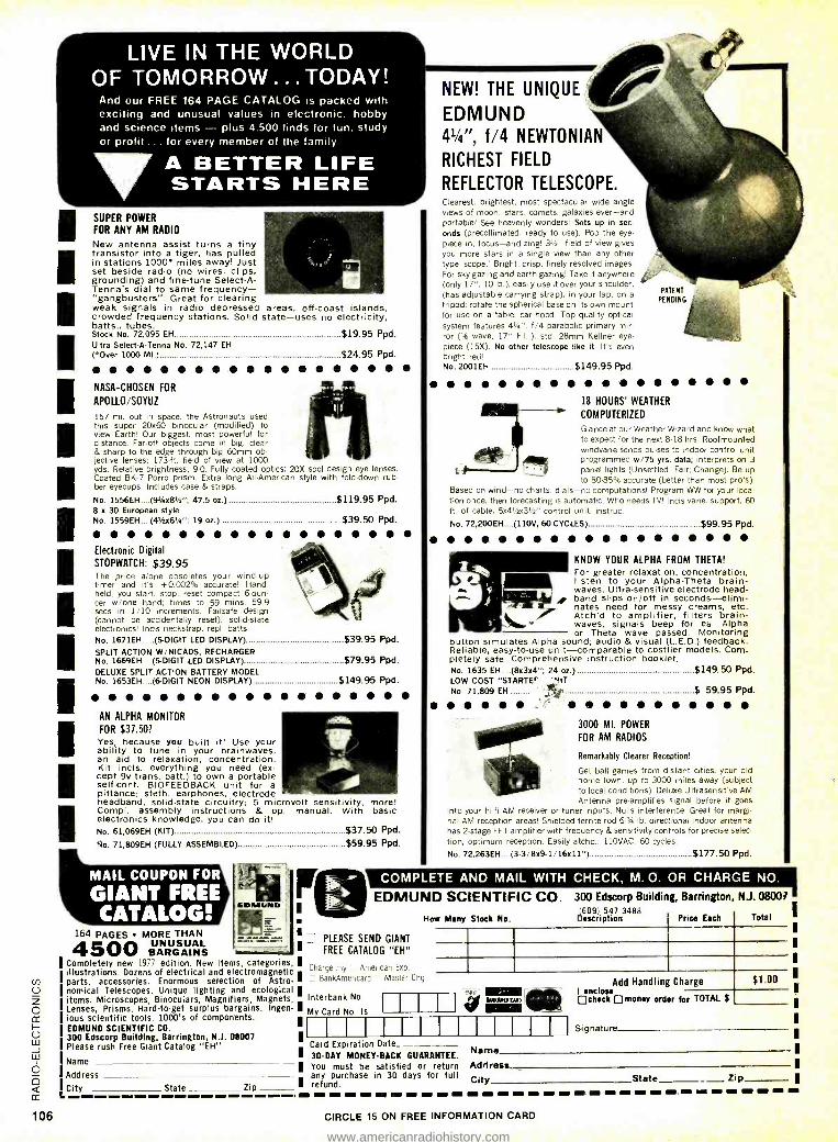
1
1
1 1 1
1 1
1
1
1 1
1
LIVE IN THE WORLD OF TOMORROW ...TODAY!
And our FREE 164 PAGE CATALOG is packed with exciting and unusual values in electronic, hobby and science items plus 4.500 finds for fun, study or profit ... for every member of the family
lyA BETTER LIFE STARTS HERE
SUPER POWER
FOR ANY AM RADIO
New antenna assist turns a tiny transistor into a tiger, has pulled in stations 1000° miles away! Just set beside radio (no wires, clips, grounding) and fine -tune Select -A- Tenna's dial to same frequency - "gangbusters"! Great for clearing weak signals in radio depressed areas, off-coast islands, crowded frequency stations. Solid state -uses no electricity, batts., tubes. Stock No. 72,095 EH
Ultra Select- A -Tenna No. 72,147 EH ( .Over 1000 MI.)..
NASA -CHOSEN FOR
APOLLO /SOYUZ
157 mi. out in space, the Astronauts used this super 20x60 binocular (modified) to view Earth! Our biggest, most powerful for distance. Far -off objects come in big, clear & sharp to the edge through big 60mm ob- jective lenses; 173 -ft. field of view at 1000 yds. Relative brightness, 9.0. Fully coated optics; 20X spcl design eye lenses. Coated BK-7 Porro prism. Extra long All- American style with fold -down rub- ber eyecups. Includes case & straps.
No. 1556EH....(94u8' "; 47.5 oz.) .................... ........................$119.95 Ppd. 8 x 30 European style No. 1559EH....(41/2x61/4": 19 oz.) $39.50 Ppd.
Electronic Digital
STOPWATCH: $39.95 The price alone obsoletes your wind-up timer and its +0.002% accurate! Hand- held, you start, stop, reset compact 6-oun- cer w /one hand; times to 59 mins, 59.9 secs in 1 /10 increments. Failsafe design (cannot be accidentally reset), solid -state electronics! Inds neckstrap, repl. batts. No. 1671EH (5 -DIGIT LED DISPLAY) $39.95 Ppd.
No. 1669EH....(5 -DIGIT LED DISPLAY) $79.95 Ppd. DELUXE SPLIT ACTION BATTERY MODEL
$19.95 Ppd.
$24.95 Ppd.
SPLIT ACTION W /NICADS, RECHARGER
No. 1653EH (6-DIGIT NEON DISPLAY) $149.95 Ppd.
AN ALPHA MONITOR
FOR $37.50? Yes, because you built it! Use your ability to tune in your brainwaves, an aid to relaxation, concentration. Kit incls. everything you need (ex- cept 9v trans. batt.) to own a portable self-cont. BIOFEEDBACK unit for a pittance: steth. earphones, electrode headband, solid -state circuitry; 5 microvolt sensitivity, more! Compl. assembly instructions & op. manual. With basic electronics knowledge, you can do it! No. 61,069EH (KIT) $37.50 Ppd.
No. 71,809EH (FULLY ASSEMBLED) $59.95 Ppd.
MAIL COUPON FOR
GIANT FREE CATALOG!
164 PAGES MORE THAN UNUSUAL BARGAINS .
Completely new 1977 edition. New items, categories, illustrations. Dozens of electrical and electromagnetic
V) parts, accessories. Enormous selection of Astro- O nomical Telescopes. Unique lighting and ecological E items. Microscopes, Binoculars, Magnifiers, Magnets, O Lenses, Prisms. Hard -to -get surplus bargains. Ingen- CC ious scientific tools. 1000's of components.
I- EDMUND SCIENTIFIC CO.
u1 300 Edscorp Building, Barrington, N.J. 08007
J Please rush Free Giant Catalog "EH ". Lu
Name O E < City State Zip - cc L
Address -.
106
NEW! THE UNIQUE
EDMUND 41/4 ", f/4 NEWTONIAN
RICHEST FIELD
REFLECTOR TELESCOPE. Clearest, brightest, most spectacular wide angle views of moon, stars, comets, galaxies ever -and portable! See heavenly wonders! Sets up in sec-
onds (precollimated, ready to use). Pop the eye-
piece in, focus -and zing! 31/2` field of view gives you more stars in a single view than any other type 'scope.' Bright, crisp, finely resolved images. For sky gazing and earth gazing! Take it anywhere (only 17", 10 lb.), easily use it over your shoulder. (has adjustable carrying strap), in your lap, on a
tripod; rotate the spherical base on its own mount for use on a table, car hood. Top quality optical system features 41 ", f/4 parabolic primary mir- ror ('/a wave, 17" F.L.); std. 28mm Kellner eye-
piece (15X). No other telescope like it. It's even bright red! No. 2001EH $149.95 Ppd.
18 HOURS' WEATHER
COMPUTERIZED
Glance at our Weather Wizard and know what to expect for the next 8 -18 hrs. Roofmounted windvane sends pulses to indoor control unit programmed w/75 yrs. data; interprets on 3 panel lights (Unsettled; Fair; Change). Be up to 80 -85% accurate (better than most pro's)!
Based on wind -no charts, dials -no computations! Program WW for your loca- tion once, then forecasting is automatic. Who needs TV! Inds vane, support, 60 ft. of cable. 5x4' /2e3'-s" control unit, instruc.
No. 72,200EH....(110V, 60 CYCLES)....................... ...... ...... .........$99.95 Ppd.
PATENT
PENDING
t#
KNOW YOUR ALPHA FROM THETA!
For greater relaxation, concentration, listen to your Alpha -Theta brain - waves. Ultra- sensitive electrode head- band slips on /off in seconds- elimi- nates need for messy creams, etc. Atch'd to amplifier, filters brain - waves, signals beep for ea. Alpha or Theta wave passed. Monitoring
button simulates Alpha sound; audio & visual (L.E.D.) feedback. Reliable, easy -to -use unit -comparable to costlier models. Com- pletely safe. Comprehensive instruction booklet. No. 1635 EH....(8x3x4'; 24 oz.) $149.50 Ppd. LOW COST "STARTEr 'HIT No. 71,809 EH '=, $ 59.95 Ppd.
3000 MI. POWER
FOR AM RADIOS
Remarkably Clearer Reception!
Get ball games from distant cities, your old home town, up to 3000 miles away (subject to local conditions). Deluxe Ultrasensitive AM Antenna pre-amplifies signal before it goes
into your hi -fi AM receiver or tuner inputs. Nulls interference. Great for margi- nal AM reception areas! Shielded ferrite rod 6 -3/4 lb. directional indoor antenna has 2 -stage FET amplifier with frequency & sensitivity controls for precise selec- tion, optimum reception. Easily atchd.; 110VAC. 60 cycles.
No. 72,263EH....(3- 3/8x9.1 /16x11 ") $177.50 Ppd.
COMPLETE AND MAIL WITH CHECK, M. O. OR CHARGE NO.
EDMUND SCIENTIFIC CO. 300 Edscorp Building, Barrington, NJ. 08007 (609) 597 -3488
Stock No. Description Price Each Total How Many
PLEASE SEND GIANT FREE CATALOG "EH"
Charge my American Exp
BankAmencard - Master Chg
Interbank No.
My Card No. Is IIIIIII I_I11III I1f
Add Handling Charge
lMIMI TAN" I enclose MIME check ['money order for TOTAL $ gow
Card Expiration Date
30 -DAY MONEY -BACK GUARANTEE. You must be satisfied or return any purchase in 30 days for full refund.
Signature
$1.00
Name
Address City State Zip
CIRCLE 15 ON FREE INFORMATION CARD
I
www.americanradiohistory.com

Introducing D3
-significantly higher "activity" ratios. -inc-edibly low parts -per -billion but highly
effective arti- static system. -a chemical "release system" that allows fluid
anc suspended compounds to pull away from record micro -grooves.
THE SUPERIOR RECORD CLEANER
CAU'IOh KEEF JUT OF REACH OF CHILDREN
Net Contents 16 FI. Oz.
MADE IN U S A.
1+E SUPERIOR RECORD GLEAM"
ï.ìl TION
<:Eì' OUT OF REACH OF CFMlORE11
Conlants t ti ox. (21-35°C) MADE IN" USA
Only from Discwasher lak ls.
Better performEance without increased price.
id1407 N. PRCVIDENCE COLUMBIA, MO 65201
Discwasher Group
CIR LE 33 ON FREE INFORMATION CARD www.americanradiohistory.com

THE COBRA 32XLR. A TECHNOLOGICAL PUNCHTHROUGH. Cobra has a reputation for punching through loud and clear. The new Cobra 32XLR, of course, con- tinues the reputation. And creates another -for
innovative design, superb engineering and technical superiority.
Start with the illuminated 4 -in -1 meter. It tells you exactly how much power you're pushing out and pulling in. As well as monitoring your modulation in precise percentages. And measuring your punch with an SWR check. In short, the 32 XLR lets you keep an eye on your ears.
ScanAlert, Cobra's unique scan- ning system, continually monitors Channel 9 when you're on another channel. If an emergency comes up, the ScanAlert light goes on. And the incoming message automat- ically locks the receiver on the active channel.
For information on our complete line write for brochure #CB -2.
CIRCLE 12 ON FREE
The 32XLR's Digital Channel Selector is the very latest. With large LED numerals - for a read -out that registers clearly and
quickly. Plus switchable "pulse block" noise blank- ing that rejects short -pulse noise not normally blocked by other systems. Which makes it the most effective in the business. Finally, add automatic noise limiting, Dynamike Plus (with built -in power mike) and Delta Tuning.
The new Cobra 32XLR. It has virtually every- thing. And it has everything to do just one thing. Punch through loud and clear.
b ra Punches through loud and clear.
Cobra Communications Products DYNASCAN CORPORATION
6460 W. Cortland. St., Chicago, Illinois 60635
INFORMATION CARD www.americanradiohistory.com