Embed Size (px)
Citation preview
DTIC FILE COpy 9
Winter Bridging Exercise on Thick IceFort McCoy, Wisconsin, 1988Barry Coutermarsh April 1990
N00(0(V)N
DTICJUN 2 2 1990
D1STRT-BUTiO-7 - ;TATi v .N;T AK pr ,_, I,:. c~, ,'- Jte
Special Report 90-10
U.S. Army Corpsof EngineersCold Regions Research &Engineering Laboratory
Winter Bridging Exercise on Thick IceFort McCoy, Wisconsin, 1988Barry Coutermarsh April 1990
OTIC
Accession ForNTI SGRA&IDTIC TABUnannlounced Eljust ification--- -- --
By
Distribution/_AvailabilitY CodeS
!Avail and/or
Dist Special
Prepared for
OFFICE OF THE CHIEF OF ENGINEERS
Approved for public release; distribution Is unlimited. wO 06 2Z 1iO
PREFACEThis report was prepared by Barry Coutermarsh, Research Civil Engineer,
Applied Research Branch, Experimental Engineering Division, U.S. Army ColdRegions Research and Engineering Laboratory. Funding was provided by DAProject 4A762730AT42; Task, Army Mobility; Work Unit CS001.
Technical review was provided by Major Randy Hill and Paul Richmond, both ofCRREL.
The contents of this report are not to be used for advertising or promotionalpurposes. Citation of brand names does not constitute an official endorsement orapproval of the use of such commercial products.
ii

CONVERSION FACTORS:U.S. CUSTOMARY TO METRIC (SI) UNITS OF MEASUREMENT
These conversion factors include all the significant digits given in the conversiontables in the ASTM Metric Practice Guide (E 380), which has been approved for useby the Department of Defense. Converted values should be rounded to have thesame precision as the original (see E 380).
Multiply By To obtain
inch 25.4 millimeterinch2 0.00064516 meter'foot 0.3048 meterfoot2 0.09290304 meter2pound (mass) 0.4535924 kilogramton (short) 907.1847 kilogrampound/inch2 6894.757 pascalpound/foot 14.59390 newton/meter
iii
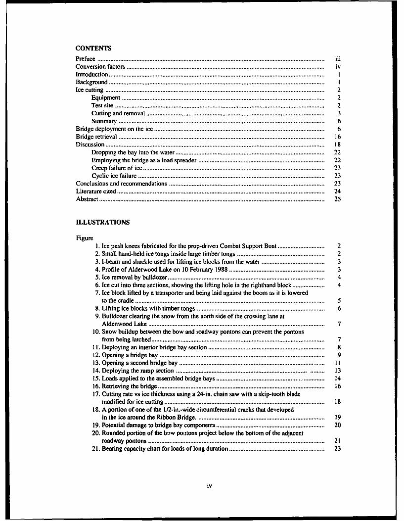
CONTENTSPreface ............................................................................................................................................ iii
Conversion factors .......................................................................................................................... ivIntroduction ..................................................................................................................................... IBackground ..................................................................................................................................... IIce cutting ....................................................................................................................................... 2
Equipm ent ............................................................................................................................. 2Test site ................................................................................................................................. 2Cutting and rem oval ............................................................................................................ 3Sum m ary ............................................................................................................................... 6
Bridge deploym ent on the ice ......................................................................................................... 6Bridge retrieval ............................................................................................................................... 16D iscussion ....................................................................................................................................... 18
D ropping the bay into the water ............................................................................................ 22Em ploying the bridge as a load spreader .............................................................................. 22Creep failure of ice ................................................................................................................ 23Cyclic ice failure ................................................................................................................... 23
Conclusions and recom m endations ................................................................................................ 23Literature cited ................................................................................................................................ 24Abstract ........................................................................................................................................... 25
ILLUSTRATIONS
FigureI. Ice push knees fabricated for the prop-driven Combat Support Boat ............................. 22. Sm all hand-held ice tongs inside large tim ber tongs ...................................................... 23. I-beam and shackle used for lifting ice blocks from the water ....................................... 34. Profile of A lderwood Lake on 10 February 1988 ........................................................... 35. Ice rem oval by bulldozer ................................................................................................. 46. Ice cut into three sections, showing the lifting hole in the righthand block .................... 47. Ice block lifted by a transporter and being laid against the boom as it is lowered
to the cradle ..................................................................................................................... 58. Lifting ice blocks w ith tim ber tongs .............................................................................. . 69. Bulldozer clearing the snow from the north side of the crossing lane at
A ldenwood Lake ............................................................................................................ 710. Snow buildup between the bow and roadway pontons can prevent the pontons
from being latched .......................................................................................................... 711. Deploying an interior bridge bay section ........................................................................ 812. Opening a bridge bay ...................................................................................................... 913. O pening a second bridge bay .......................................................................................... 1114. Deploying the ram p section ................................................................................. ......... 1315. Loads applied to the assem bled bridge bays ................................................................... 1416. Retrieving the bridge ....................................................................................................... 1617. Cutting rate vs ice thickness using a 24-in. chain saw with a skip-tooth blade
m odified for ice cutting ................................................................................................... 1818. A portion of one of the 12-iu.-wide circumferential cracks that developed
in the ice around the Ribbon Bridge .............................................................................. 1919. Potential dam age to bridge bay com ponents ................................................................... 2020. Rounded portion of the bow poatons project below the bottom of the adjacent
roadway pontons ............................................................................................................ 2121. Bearing capacity chart for loads of long duration ........................................................... 23
iv
Winter Bridging Exercise on Thick Ice
Fort McCoy, Wisconsin, 1988
BARRY COUTERMARSH
INTRODUCTION Ribbon Bridge. Stubstad et al. (1984) suggest thatthe Combat Support Boat can break up the ice
One of the-most vexing situations encountered cover in this thickness range. Additionally, chainby an army on the move in winter is the need to saws can cut 8 in. of ice relatively quickly. The icecross an ice-covered river. If this ice cover is not blocks can then be removed from the waterway bythick enough to support the anticipated loads, yet bulldozer if the topography allows it to work fromis thicker than what can be easily removed (less the water onto the shore. Melor and Calkins (1988)than 8 in.), the problem becomes very difficult, detail an exercise in South Korea that used this
This report describes awinterbridging exercise technique after the ice had been both cut withundertaken by CRREL and the 2nd Combat Engi- chain saws and broken up by blasting. Blasting isneer Battalion, 2nd Marine Division FMF,on22-26 not recommended unless special techniques areFebruary 1988 at Fort McCoy, Wisconsin. The ex- employed that clear some of the ice from theercise investigated the difficulties of bridging a crossing zone. Coutermarsh (1987) details anotherwaterway with a substantial ice cover present and exercise in South Korea that demonstrated theexperimented with some options that very difficult conditions caused by fractured icewere chosen to be compatible with equipment after blasting a crossing zone by conventionalnormally found with a Ribbon Bridge unit. The techniques.only special equipment or materials considered In the initial planning of the Fort McCoy exer-were those that could be easily fabricated or pro- cise, we expected the ice to be 18 to 20 in. thick.cured if found effective. However, the weather before the bridging exer-
cise was very cold, which resulted in an average24.5-in.-thick ice cover at the bridging site. We
BACKGROUND planned to use chain saws to cut the ice into floesof manageable size, with one saw using a chain
It has been shown that ice covers up to 8 in. thick modified for faster ice cutting. The blocks werecan be removed relatively easily from a crossing then to be removed by various techniques to assesszone to provide a dear deployment area for the the relative speed and effectiveness of each. Bull-
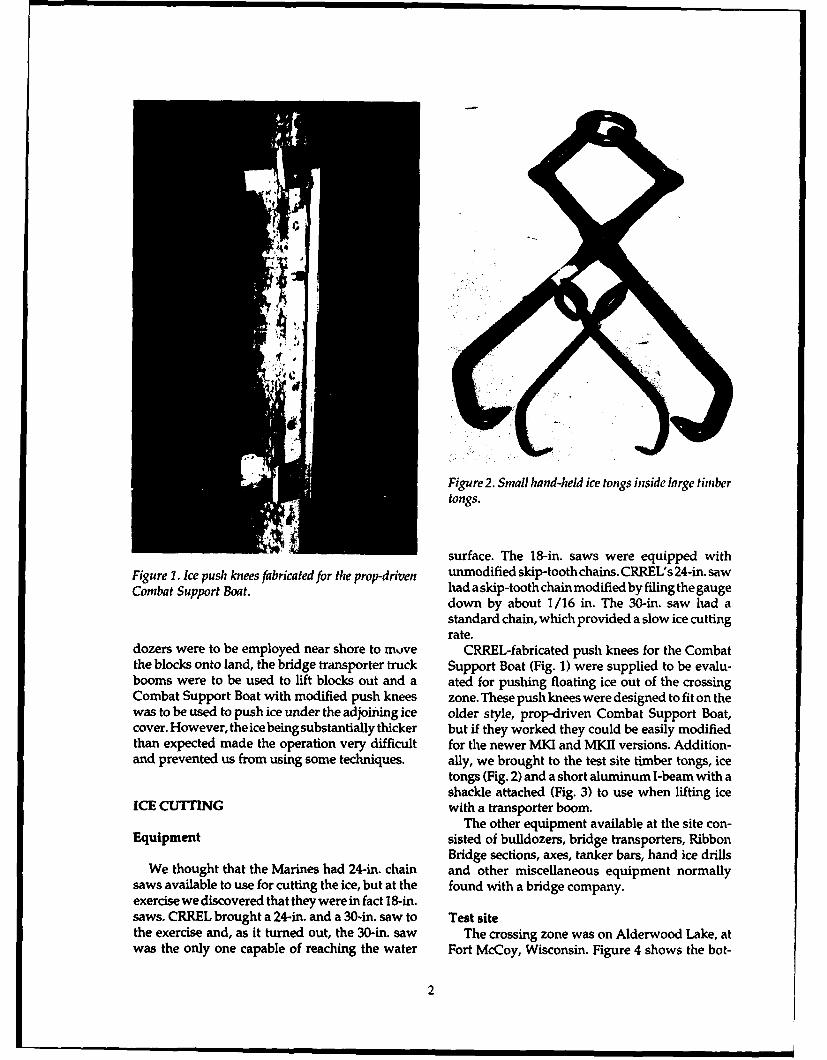
Figure 2. Small hand-held ice tongs inside large timbertongs.
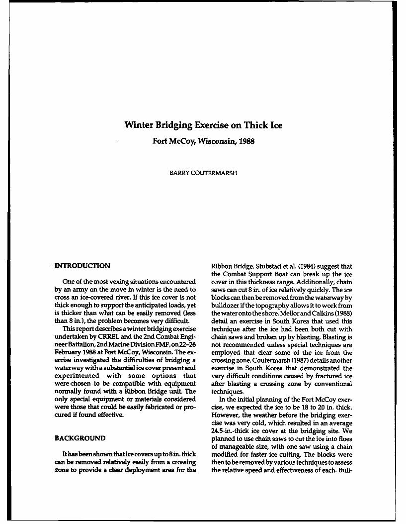
surface. The 18-in. saws were equipped withFigure 1. Ice push knees fabricated for the prop-driven unmodified skip-tooth chains. CRREL's 24-in. sawCombat Support Boat. had a skip-tooth chain modified by filing the gauge
down by about 1/16 in. The 30-in. saw had astandard chain, which provided a slow ice cuttingrate.
dozers were to be employed near shore to move CRREL-fabricated push knees for the Combatthe blocks onto land, the bridge transporter truck Support Boat (Fig. 1) were supplied to be evalu-booms were to be used to lift blocks out and a ated for pushing floating ice out of the crossingCombat Support Boat with modified push knees zone. These push knees were designed to fit on thewas to be used to push ice under the adjoining ice older style, prop-driven Combat Support Boat,cover. However, the ice being substantially thicker but if they worked they could be easily modifiedthan expected made the operation very difficult for the newer MKI and MKII versions. Addition-and prevented us from using some techniques, ally, we brought to the test site timber tongs, ice
tongs (Fig. 2) and a short aluminum I-beam with ashackle attached (Fig. 3) to use when lifting ice
ICE CUTTING with a transporter boom.The other equipment available at the site con-
Equipment sisted of bulldozers, bridge transporters, RibbonBridge sections, axes, tanker bars, hand ice drills
We thought that the Marines had 24-in. chain and other miscellaneous equipment normallysaws available to use for cutting the ice, but at the found with a bridge company.exercise we discovered that they were in fact 18-in.saws. CRREL brought a 24-in. and a 30-in. saw to Test sitethe exercise and, as it turned out, the 30-in. saw The crossing zone was on Alderwood Lake, atwas the only one capable of reaching the water Fort McCoy, Wisconsin. Figure 4 shows the bot-
2
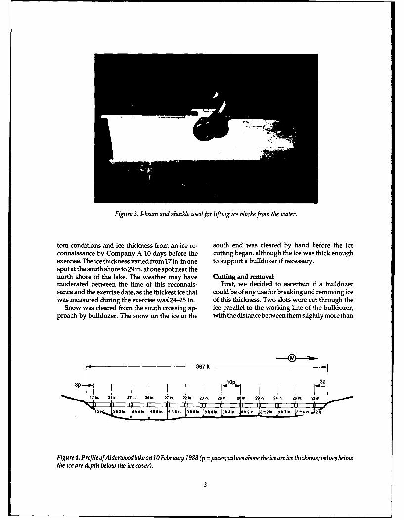
Figure 3. I-beam and shackle used for lifting ice blocks from the water.
tom conditions and ice thickness from an ice re- south end was cleared by hand before the iceconnaissance by Company A 10 days before the cutting began, although the ice was thick enoughexercise. The ice thickness varied from 17 in. in one to support a bulldozer if necessary.spot at the south shore to 29 in. at one spot near thenorth shore of the lake. The weather may have Cutting and removalmoderated between the time of this reconnais- First, we decided to ascertain if a bulldozersance and the exercise date, as the thickest ice that could be of any use for breaking and removing icewas measured during the exercise was 24-25 in. of this thickness. Two slots were cut through the
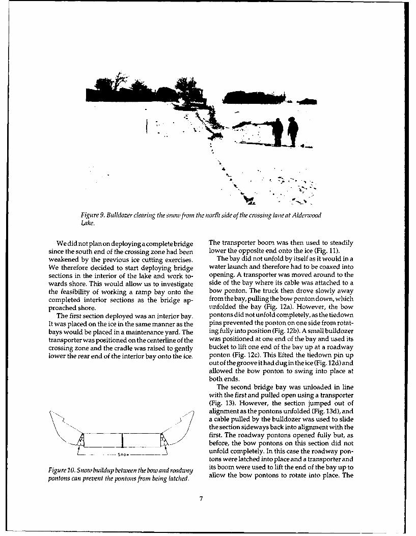
Snow was cleared from the south crossing ap- ice parallel to the working line of the bulldozer,proach by bulldozer. The snow on the ice at the with the distance between them slightly more than
Figu re 4. P rofile of Alderwood lake on 20 February 1988 (p = paces; values above the ice are ice thickness; values belowthe ice are depth below the ice cover).
37f
Ice
Slots Cut in Ice
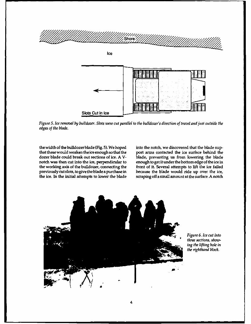
Figure 5. Ice removal by bulldozer. Slots were cut parallel to the bulldozer's direction of travel and just outside theedges of the blade.
the width of thebuldozer blade (Fig. 5). We hoped into the notch, we discovered that the blade sup-that these would weaken the ice enough so that the port arms contacted the ice surface behind thedozer blade could break out sections of ice. A V- blade, preventing us from lowering the bladenotch was then cut into the ice, perpendicular to enough to getit under the bottom edge of the ice inthe working axis of the bulldozer, connecting the front of it. Several attempts to lift the ice failedpreviouslycutslots, to give the blade a purchase in because the blade would ride up over the ice,the ice. In the initial attempts to lower the blade scraping off a small amount at the surface. A notch
•. Figure 6. Ice cut into
ing the lifting hole inthe righthand block.
4
much wider at the top would have been needed to from slipping back out the hole and created aallow the bulldozer blade to get under the ice to lift convenient way of lifting an ice section.it up. The ice cutting was extremely slow and was
We tried shaving the ice off behind the notch easily the limiting factor during this procedure.with the bulldozer but the blade had little effect When using chain saws to cut ice, the cutting rateupon the ice. After several attempts, this technique is highly dependant upon ice thickness and chainwas given up as being impractical. We considered design. Skip-tooth chains cut ice faster than con-cutting the notch back with the chain saw, but with ventional chains, but are still substantially slowerthe thick ice that was present it was evident that a than chains with the gauge filed down (Couter-very long chain saw blade held at a low angle marsh 1989). Furthermore, when the ice thicknesswould be necessary. This would be difficult, if not approaches or exceeds the length of the bar, theimpossible, for a human operator to handle. cutting rate is further reduced. Our cutting opera-
We were curious about what could be accom- tions were seriously hindered from the beginningplished with rippers on the back of a bulldozer, but by saws incapable of penetrating the full ice thick-were unable to obtain them. Perhaps if the teeth ness. This added the problem of how to finish thecould break the ice, the blade could then be used to cut to the water to free the ice floes.clear the debris. This procedure could of course The 18-in. chain saws were used to initially cutonly be used where the river topography allowed the ice down as far as they could. The saws did notthe bulldozer to work in the water. perform well in the ice and stoppages for various
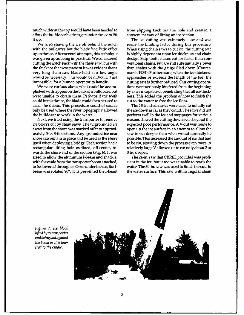
Next, we tried using the transporter to remove reasons slowed the cutting down even beyond theice blocks cut by chain saws. The ungrounded ice expected poor performance. A V-cut was made toaway from the shore was marked off into approxi- open up the ice surface in an attempt to allow themately 5- x 8-ft sections. Any grounded ice near saw to cut deeper than what would normally beshore can remain in place and be used as the shore possible. This increased the amount of ice that haditself when deploying a bridge. Each section had a to be cut, slowing down the process even more. Arectangular lifting hole outlined, off-center, to- relatively large V allowed us to cut only about 2 orwards the shore end of the section (Fig. 6). It was 3 in. deeper.sized to allow the aluminum I-beam and shackle, The 24-in. saw that CRREL provided was profi-with the cable from the transporter boom attached, cient in the ice, but it too was unable to reach theto be lowered through it. Once under the ice, the I- water. The 30-in. saw was used to finish the cuts tobeam was rotated 900. This prevented the I-beam the water surface. This saw with its regular chain
Figure 7. Ice blocklifted bya transporterand being laidagainst .
the boom as it is low-ered to the cradle.
5
can approach and depart on the road that will be, , . used for the bridge itself.
The size of the block that can be lifted by thismethod may be limited by the ice thickness. As theice gets thinner, it is less able to support its ownweight and may fail in bending as it is lifted out ofthe water, so the block-size-to-ice-thickness ratioshould be determined to define what size blockshould be cut in ice of various thicknesses.
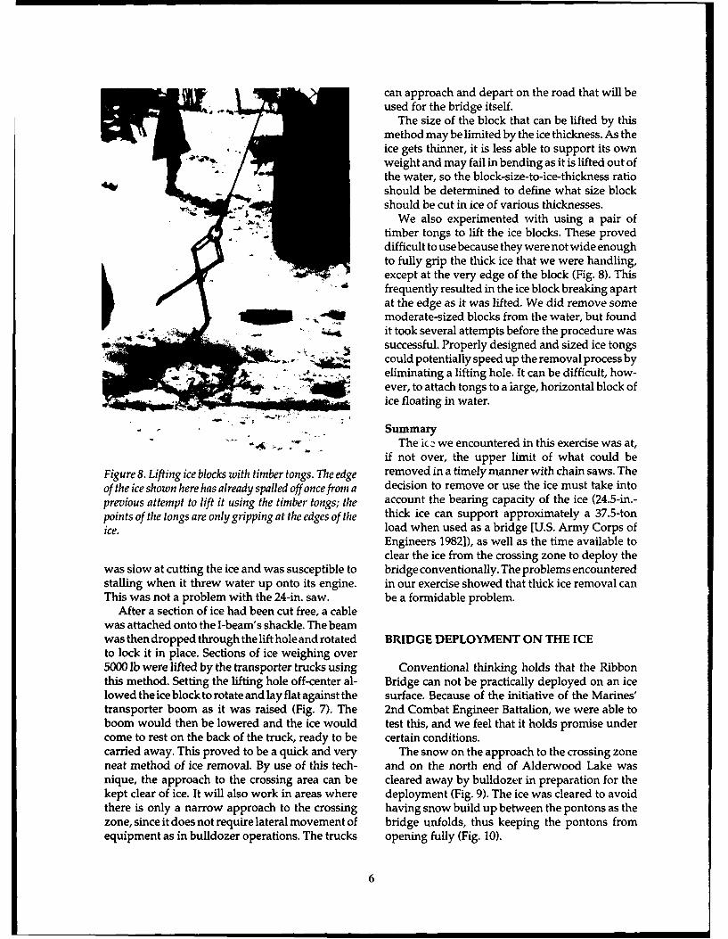
" We also experimented with using a pair oftimber tongs to lift the ice blocks. These proveddifficult to use because they were not wide enoughto fully grip the thick ice that we were handling,except at the very edge of the block (Fig. 8). Thisfrequently resulted in the ice block breaking apartat the edge as it was lifted. We did remove somemoderate-sized blocks from the water, but foundit took several attempts before the procedure wassuccessful. Properly designed and sized ice tongs
. 6 could potentially speed up the removal process by- .eliminating a lifting hole. It can be difficult, how-
ever, to attach tongs to a large, horizontal block ofice floating in water.
SummaryThe ice we encountered in this exercise was at,
if not over, the upper limit of what could beFigure 8. Lifting ice blocks with timber tongs. The edge removed in a timely manner with chain saws. Theof the ice shown here has already spalled off once from a decision to remove or use the ice must take intoprevious attempt to lift it using the timber tongs; the account the bearing capacity of the ice (24.5-in.-points of the tongs are only gripping at the edges of the thick ice can support approximately a 37.5-tonice. load when used as a bridge [U.S. Army Corps of
Engineers 1982]), as well as the time available toclear the ice from the crossing zone to deploy the
was slow at cutting the ice and was susceptible to bridge conventionally. The problems encounteredstalling when it threw water up onto its engine. in our exercise showed that thick ice removal canThis was not a problem with the 24-in. saw. be a formidable problem.
After a section of ice had been cut free, a cablewas attached onto the I-beam's shackle. The beamwas then dropped through the lift hole and rotated BRIDGE DEPLOYMENT ON THE ICEto lock it in place. Sections of ice weighing over5000 lb were lifted by the transporter trucks using Conventional thinking holds that the Ribbonthis method. Setting the lifting hole off-center al- Bridge can not be practically deployed on an icelowed the ice block to rotate and lay flat against the surface. Because of the initiative of the Marines'transporter boom as it was raised (Fig. 7). The 2nd Combat Engineer Battalion, we were able toboom would then be lowered and the ice would test this, and we feel that it holds promise undercome to rest on the back of the truck, ready to be certain conditions.carried away. This proved to be a quick and very The snow on the approach to the crossing zoneneat method of ice removal. By use of this tech- and on the north end of Alderwood Lake wasnique, the approach to the crossing area can be cleared away by bulldozer in preparation for thekept clear of ice. It will also work in areas where deployment (Fig. 9). The ice was cleared to avoidthere is only a narrow approach to the crossing having snow build up between the pontons as thezone, since it does not require lateral movement of bridge unfolds, thus keeping the pontons fromequipment as in bulldozer operations. The trucks opening fully (Fig. 10).
6
S 1, . o- °.
Figure 9. Bulldozer clearing the snow from the norfh side of the crossing lane at AlderwoodLake.
We did not plan on deploying a completebridge The transporter boom was then used to steadilysince the south end of the crossing zone had been lower the opposite end onto the ice (Fig. 11).weakened by the previous ice cutting exercises. The bay did not unfold by itself as it would in aWe therefore decided to start deploying bridge water launch and therefore had to be coaxed intosections in the interior of the lake and work to- opening. A transporter was moved around to thewards shore. This would allow us to investigate side of the bay where its cable was attached to athe feasibility of working a ramp bay onto the bow ponton. The truck then drove slowly awaycompleted interior sections as the bridge ap- from the bay, pulling the bow ponton down, whichproached shore. unfolded the bay (Fig. 12a). However, the bow
The first section deployed was an interior bay. pontons did not unfold completely, as the tiedownIt was placed on the ice in the same manner as the pins prevented the ponton on one side from rotat-bays would be placed in a maintenance yard. The ing fully into position (Fig. 12b). A small bulldozertransporter was positioned on the centerline of the was positioned at one end of the bay and used itscrossing zone and the cradle was raised to gently bucket to lift one end of the bay up at a roadwaylower the rear end of the interior bay onto the ice. ponton (Fig. 12c). This lifted the tiedown pin up
out of the groove it had dug in the ice (Fig. 12d) andallowed the bow ponton to swing into place atboth ends.
The second bridge bay was unloaded in linewith the first and pulled open using a transporter(Fig. 13). However, the section jumped out ofalignment as the pontons unfolded (Fig. 13d), anda cable pulled by the bulldozer was used to slide
"N -the section sideways back into alignment with thefirst. The roadway pontons opened fully but, as
_-____ before, the bow pontons on this section did notL - --- snow- unfold completely. In this case the roadway pon-
tons were latched into place and a transporter and
Figure 10. Snow buildup between the bow and roadway its boom were used to lift the end of the bay up to
pontons can prevent the pontons from being latched. allow the bow pontons to rotate into place. The
7
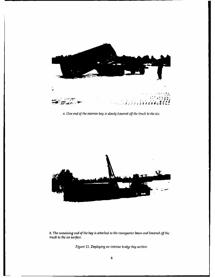
a. One end of the interior bay is slowly lowered off the truck to the ice.
b. The remaining end of the bay is attached to the transporter boom and lowered off thetruck to the ice surface.
Figure 11. Deploying an interior bridge bay section.
8
p -
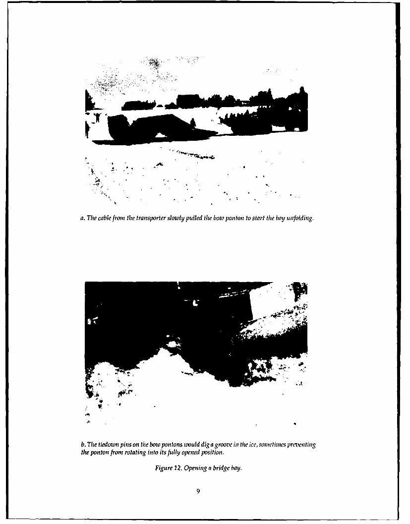
a. The cable from the transporter slowly pulled the bow ponton to start the bay unfolding.
I"i
b. The tiedown pins on the bow pontons would dig a groove in the ice, sometimes preventingthe ponton from rotating into its fully opened position.
Figure 12. Opening a bridge bay.
9
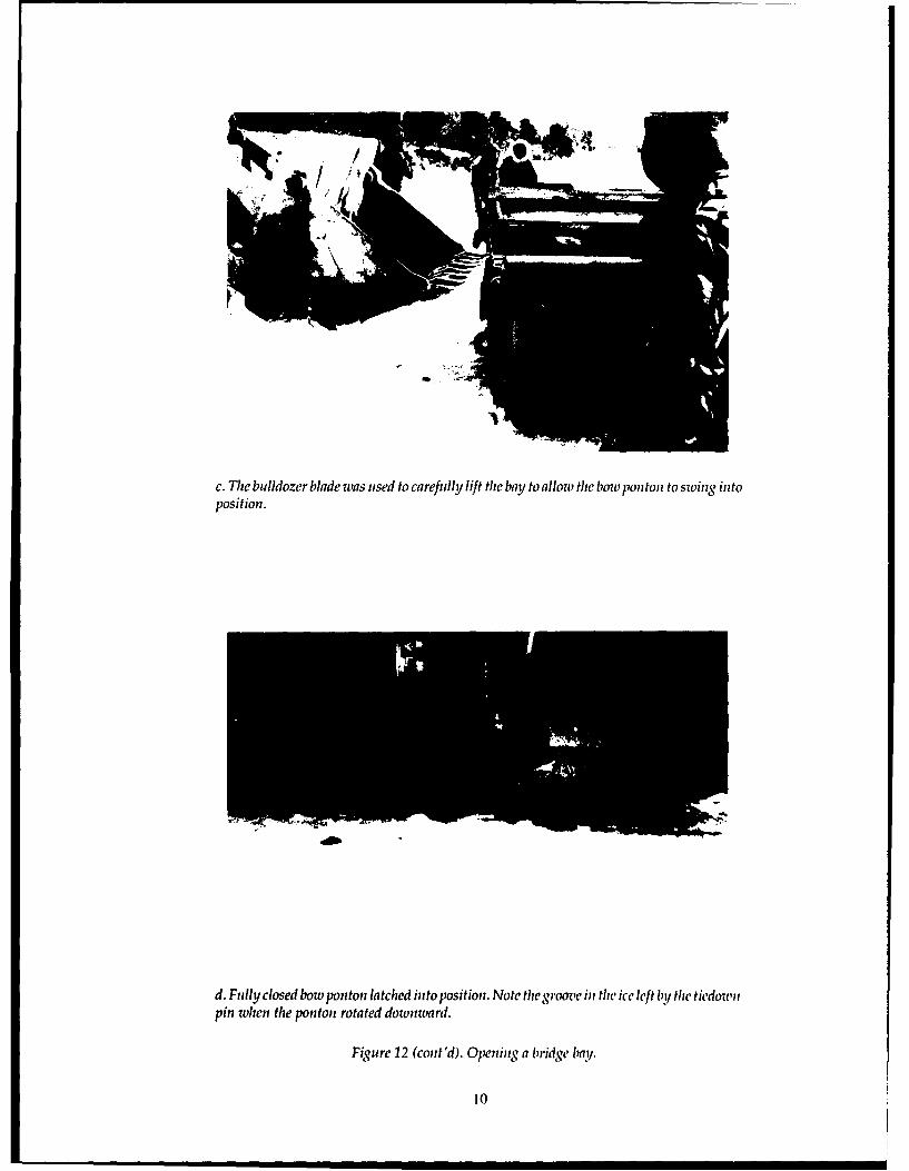
c. The bulldozer blade was used to carefully lift the bay to allow the bow ponton to swing intoposition.
d. Fully closed bow ponton latched into position. Note the groove in the ice left ly the tiedownpin when the ponton rotated downward.
Figure 12 (cont'd). Opening a bridge bay.
10
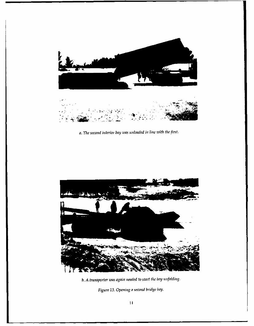
a. The second interior bay was unloaded in line with the first.
b. A transporter was again needed to start the bay unfolding.
Figure 13. Opening a second bridge bay.
I1
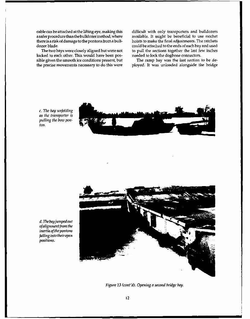
cable can be attached at the lifting eye, making this difficult with only transporters and bulldozersasaferprocedure than thebuldozer method, where available. It might be beneficial to use ratchetthere is a risk of damage to the pontons from a bull- hoists to make the final adjustments. The ratchetsdozer blade. could be attached to the ends of each bay and used
The two bays were closely aligned but were not to pull the sections together the last few incheslocked to each other. This would have been pos- needed to lock the dogbone connectors.sible given the smooth ice conditions present, but The ramp bay was the last section to be de-the precise movements necessary to do this were ployed. It was unloaded alongside the bridge
c. The bay unfoldingas the transporter ispulling the bow pon-ton.
d. The bay jumped outof alignment from theinertia of the pon tonsfalling into theiropenpositions.
Figure 13 (cont'd). Opening a second bridge bay.
12
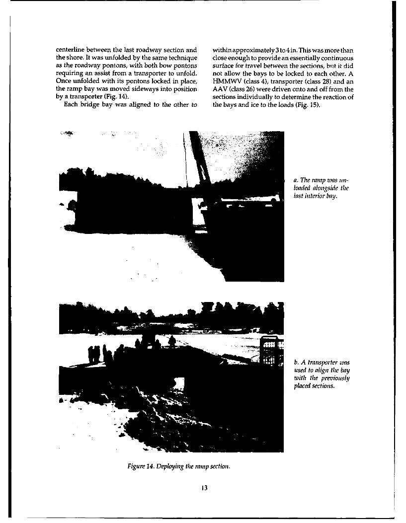
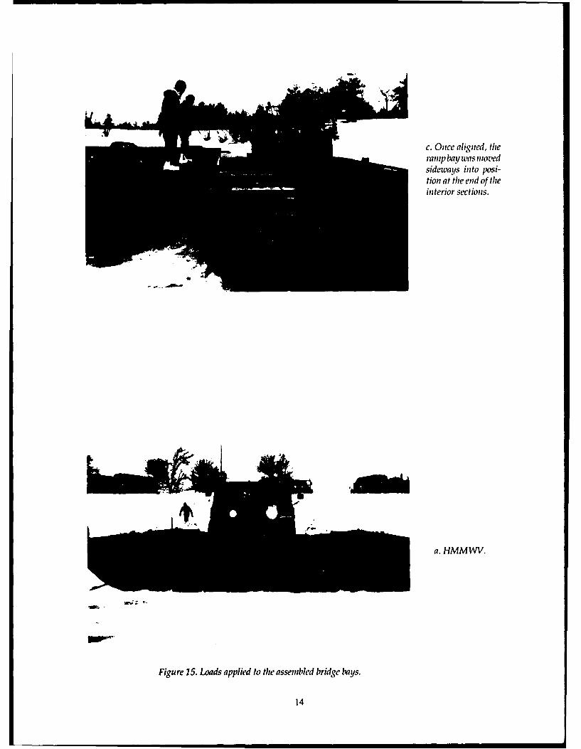
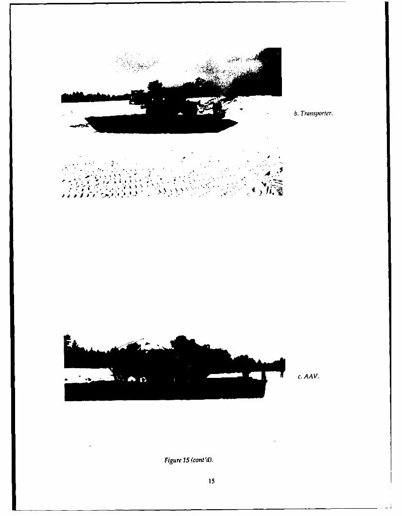
centerline between the last roadway section and within approximately 3 to 4 in. This was more thanthe shore. It was unfolded by the same technique close enough to provide an essentially continuousas the roadway pontons, with both bow pontons surface for travel between the sections, buit it didrequiring an assist from a transporter to unfold. not allow the bays to be locked to each other. AOnce unfolded with its pontons locked in place, HMMWV (class 4), transporter (class 28) and anthe ramp bay was moved sideways into position AAV (class 26) were driven onto and off from theby a transporter (Fig. 14). sections individually to determine the reaction of
Each bridge bay was aligned to the other to the bays and ice to the loads (Fig. 15).
a. The ramp was un-loaded alongside thelast interior bay.
b. A transporter wasused to align the baywith the previouslyplaced sections.
Figure 14. Deploying the ramp section.
13
c. Once aligned, theramp bay was movedsideways into posi-tion at the end of theinterior sections.
a. HMM WV.
Figure 15. Loads applied to the assembled bridge bays.
14
b. Transporter.
c. AAV.
Figure 15 (cont'd).
15
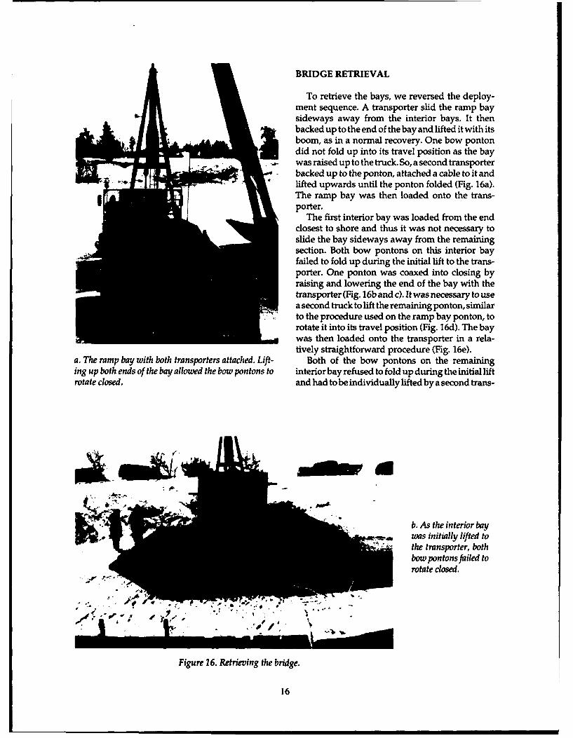
BRIDGE RETRIEVAL
To retrieve the bays, we reversed the deploy-ment sequence. A transporter slid the ramp baysideways away from the interior bays. It thenbacked up to the end of the bay and lifted it with itsboom, as in a normal recovery. One bow pontondid not fold up into its travel position as the baywas raised up to the truck. So, a second transporter
, backed up to the ponton, attached a cable to it andlifted upwards until the ponton folded (Fig. 16a).The ramp bay was then loaded onto the trans-porter.
The first interior bay was loaded from the endclosest to shore and thus it was not necessary toslide the bay sideways away from the remainingsection. Both bow pontons on this interior bayfailed to fold up during the initial lift to the trans-porter. One ponton was coaxed into closing byraising and lowering the end of the bay with thetransporter (Fig. 16b and c). It was necessary to usea second truck to lift the remaining ponton, similarto the procedure used on the ramp bay ponton, torotate it into its travel position (Fig. 16d). The baywas then loaded onto the transporter in a rela-tively straightforward procedure (Fig. 16e).
a. The ramp bay with both transporters attached. Lift- Both of the bow pontons on the remaininging up both ends of the bay allowed the bow pontons to interior bay refused to fold up during the initial liftrotate closed, and had to be individually lifted by a second trans-
b. As the interior bayh was initially lifted to
the transporter, bothbow pontons failed torotate closed.
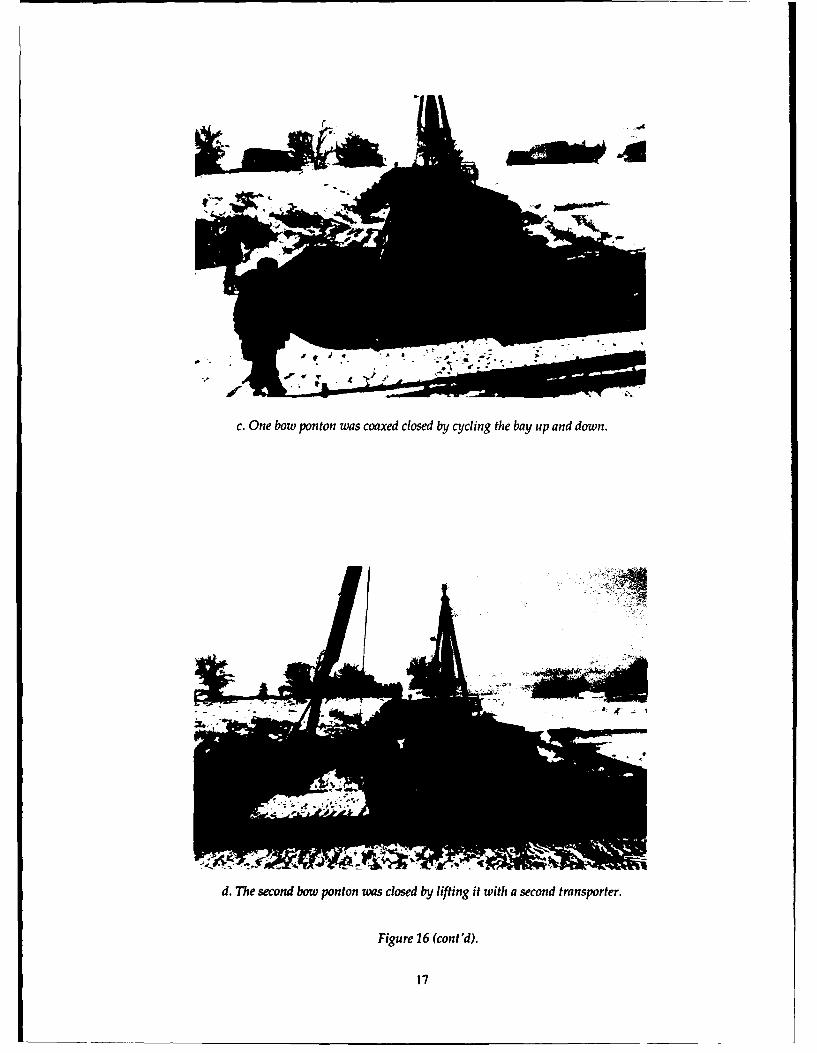
Figure 16. Retrieving the bridge.
16
UL4
c. One bow ponton was coaxed closed by cycling the bay up and down.
d. The second bow ponton was closed by lifting it with a second transporter.
Figure 16 (cont'd).
17
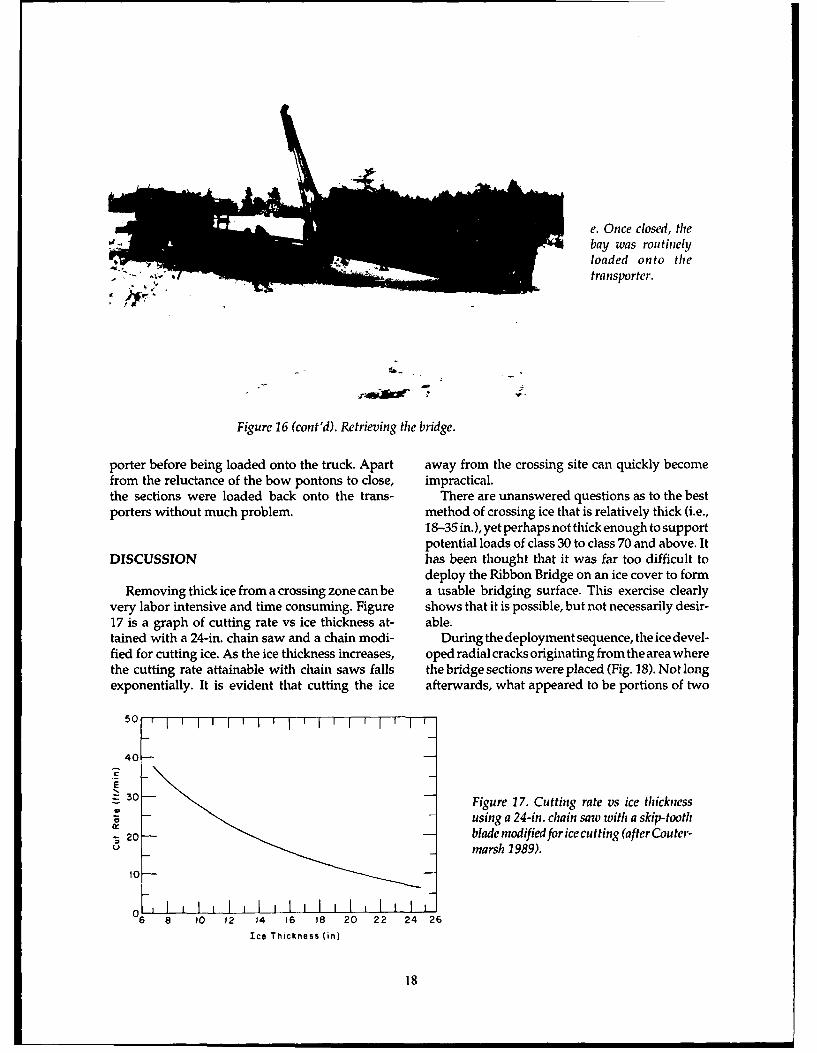
e. Once closed, thebay was routinelyloaded onto thetransporter.
Figure 16 (cont'd). Retrieving the bridge.
porter before being loaded onto the truck. Apart away from the crossing site can quickly becomefrom the reluctance of the bow pontons to close, impractical.the sections were loaded back onto the trans- There are unanswered questions as to the bestporters without much problem. method of crossing ice that is relatively thick (i.e.,
18-35 in.), yet perhaps not thick enough to supportpotential loads of class 30 to class 70 and above. It
DISCUSSION has been thought that it was far too difficult todeploy the Ribbon Bridge on an ice cover to form
Removing thick ice from a crossing zone can be a usable bridging surface. This exercise clearlyvery labor intensive and time consuming. Figure shows that it is possible, but not necessarily desir-17 is a graph of cutting rate vs ice thickness at- able.tained with a 24-in. chain saw and a chain modi- During the deployment sequence, the ice devel-fled for cutting ice. As the ice thickness increases, oped radial cracks originating from the area wherethe cutting rate attainable with chain saws falls the bridge sections were placed (Fig. 18). Not longexponentially. It is evident that cutting the ice afterwards, what appeared to be portions of two
5 0 , I I I I I I I , I I 1 I - I
40
E30 - Figure 17. Cutting rate vs ice thickness
- - using a 24-in. chain saw with a skip-tooth
- 20- blade modified for ice cutting (after Couter-U marsh 1989).
6 10 12 14 16 18 20 22 24 26
Ice Thickness (in)
18
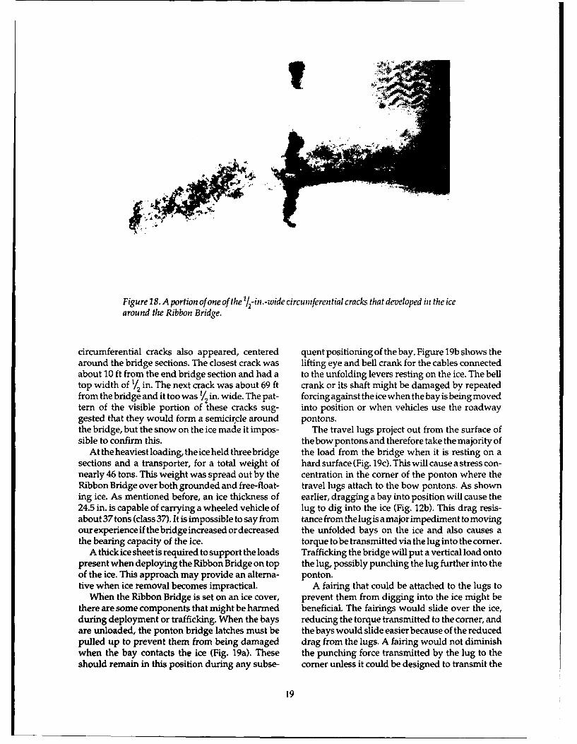
Figure 18. A portion of one of the 1/2-in.-wide circumferential cracks that developed in the icearound the Ribbon Bridge.
circumferential cracks also appeared, centered quent positioning of the bay. Figure 19b shows thearound the bridge sections. The closest crack was lifting eye and bell crank for the cables connectedabout 10 ft from the end bridge section and had a to the unfolding levers resting on the ice. The belltop width of 1/ in. The next crack was about 69 ft crank or its shaft might be damaged by repeatedfrom the bridge and it too was 1/2 in. wide. The pat- forcing against the ice when the bay is being movedtern of the visible portion of these cracks sug- into position or when vehicles use the roadwaygested that they would form a semicircle around pontons.the bridge, but the snow on the ice made it impos- The travel lugs project out from the surface ofsible to confirm this. thebow pontons and therefore take the majority of
At the heaviest loading, the ice held three bridge the load from the bridge when it is resting on asections and a transporter, for a total weight of hard surface (Fig. 19c). This will cause a stress con-nearly 46 tons. This weight was spread out by the centration in the corner of the ponton where theRibbon Bridge over both grounded and free-float- travel lugs attach to the bow pontons. As showning ice. As mentioned before, an ice thickness of earlier, dragging a bay into position will cause the24.5 in. is capable of carrying a wheeled vehicle of lug to dig into the ice (Fig. 12b). This drag resis-about 37 tons (class 37). It is impossible to say from tance from the lug is a major impediment to movingour experienceifthebridgeincreased or decreased the unfolded bays on the ice and also causes athe bearing capacity of the ice. torque to be transmitted via the lug into the corner.
A thick ice sheet is required to support the loads Trafficking the bridge will put a vertical load ontopresent when deploying the Ribbon Bridge on top the lug, possibly punching the lug further into theof the ice. This approach may provide an alterna- ponton.tive when ice removal becomes impractical. A fairing that could be attached to the lugs to
When the Ribbon Bridge is set on an ice cover, prevent them from digging into the ice might bethere are some components that might be harmed beneficial. The fairings would slide over the ice,during deployment or trafficking. When the bays reducing the torque transmitted to the corner, andare unloaded, the ponton bridge latches must be the bays would slide easier because of the reducedpulled up to prevent them from being damaged drag from the lugs. A fairing would not diminishwhen the bay contacts the ice (Fig. 19a). These the punching force transmitted by the lug to theshould remain in this position during any subse- corner unless it could be designed to transmit the
19
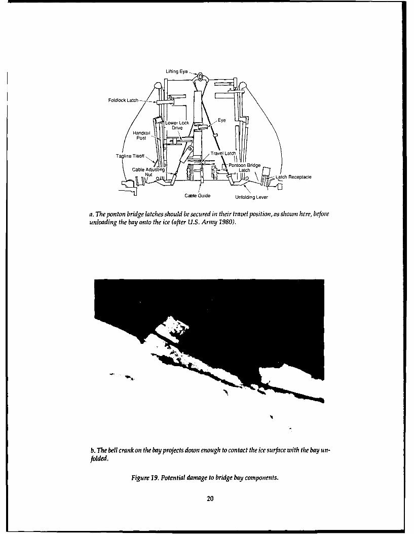
Lifting Eye ,
Foldlock Latch
HandrailPost i
Ta lineTravel Latch
Cable Adjusting LPtchNut/ Latch Receptacle
Cable Guide Unfolding Lever
a. The ponton bridge latches should be secured in their travel position, as shown here, beforeunloading the bay onto the ice (after U.S. Army 1980).
b. The bell crank on the bay projects down enough to contact the ice surface with the bay un-folded.
Figure 19. Potential damage to bridge bay components.
20
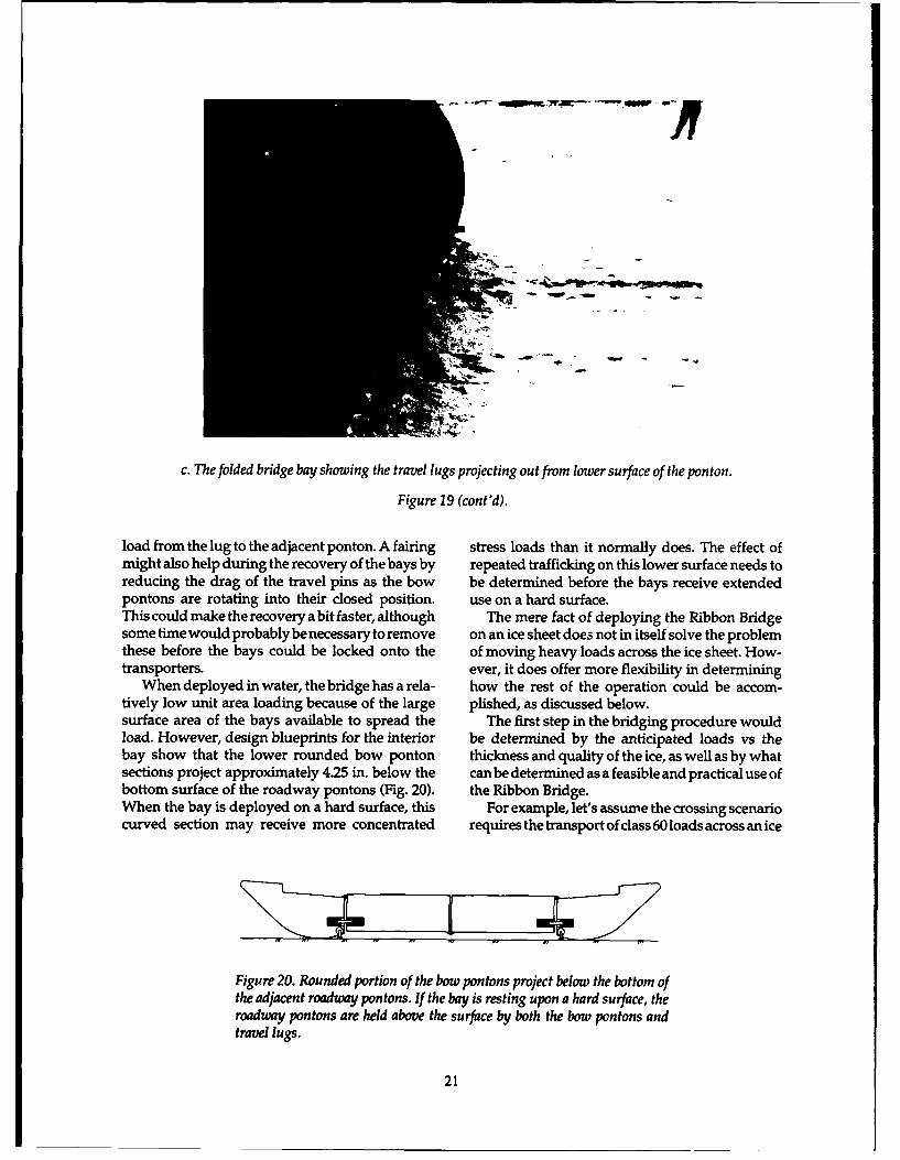
c. The folded bridge bay showing the travel lugs projecting out from lower surface of the ponton.
Figure 19 (cont'd).
load from the lug to the adjacent ponton. A fairing stress loads than it normally does. The effect ofmight also help during the recovery of the bays by repeated trafficking on this lower surface needs toreducing the drag of the travel pins as the bow be determined before the bays receive extendedpontons are rotating into their closed position. use on a hard surface.This could make the recovery a bit faster, although The mere fact of deploying the Ribbon Bridgesome time would probably be necessary to remove on an ice sheet does not in itself solve the problemthese before the bays could be locked onto the of moving heavy loads across the ice sheet. How-transporters. ever, it does offer more flexibility in determining
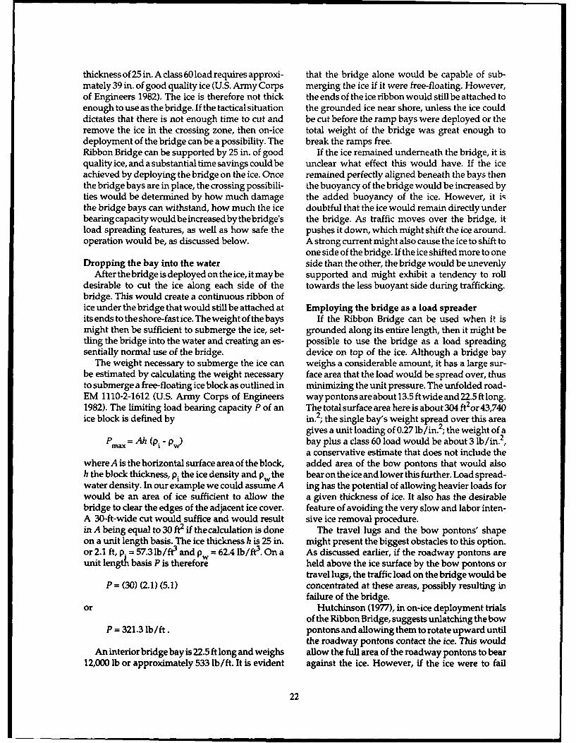
When deployed in water, the bridge has a rela- how the rest of the operation could be accom-tively low unit area loading because of the large plished, as discussed below.surface area of the bays available to spread the The first step in the bridging procedure wouldload. However, design blueprints for the interior be determined by the anticipated loads vs thebay show that the lower rounded bow ponton thickness and quality of the ice, as well as by whatsections project approximately 4.25 in. below the can be determined as a feasible and practical use ofbottom surface of the roadway pontons (Fig. 20). the Ribbon Bridge.When the bay is deployed on a hard surface, this For example, let's assume the crossing scenariocurved section may receive more concentrated requires the transport of class 60 loads across an ice
Figure 20. Rounded portion of the bow pontons project below the bottom ofthe adjacent roadway pontons. If the bay is resting upon a hard surface, theroadway pontons are held above the surface by both the bow pontons andtravel lugs.
21
thickness of 25 in. A class 60 load requires approxi- that the bridge alone would be capable of sub-mately 39 in. of good quality ice (U.S. Army Corps merging the ice if it were free-floating. However,of Engineers 1982). The ice is therefore not thick the ends of the ice ribbon would still be attached toenough to use as the bridge. If the tactical situation the grounded ice near shore, unless the ice coulddictates that there is not enough time to cut and be cut before the ramp bays were deployed or theremove the ice in the crossing zone, then on-ice total weight of the bridge was great enough todeployment of the bridge can be a possibility. The break the ramps free.Ribbon Bridge can be supported by 25 in. of good If the ice remained underneath the bridge, it isquality ice, and a substantial time savings could be unclear what effect this would have. If the iceachieved by deploying the bridge on the ice. Once remained perfectly aligned beneath the bays thenthe bridge bays are in place, the crossing possibili- the buoyancy of the bridge would be increased byties would be determined by how much damage the added buoyancy of the ice. However, it i-the bridge bays can withstand, how much the ice doubtful that the ice would remain directly underbearingcapacitywouldbeincreasedbythebridge's the bridge. As traffic moves over the bridge, itload spreading features, as well as how safe the pushes it down, which might shift the ice around.operation would be, as discussed below. A strong current might also cause the ice to shift to
one side of the bridge. If the ice shifted more to oneDropping the bay into the water side than the other, the bridge would be unevenly
After the bridge is deployed on the ice, it may be supported and might exhibit a tendency to rolldesirable to cut the ice along each side of the towards the less buoyant side during trafficking.bridge. This would create a continuous ribbon ofice under the bridge that would still be attached at Employing the bridge as a load spreaderits ends to the shore-fast ice. The weight of the bays If the Ribbon Bridge can be used when it ismight then be sufficient to submerge the ice, set- grounded along its entire length, then it might betling the bridge into the water and creating an es- possible to use the bridge as a load spreadingsentially normal use of the bridge. device on top of the ice. Although a bridge bay
The weight necessary to submerge the ice can weighs a considerable amount, it has a large sur-be estimated by calculating the weight necessary face area that the load would be spread over, thusto submerge a free-floating ice block as outlined in minimizing the unit pressure. The unfolded road-EM 1110-2-1612 (U.S. Army Corps of Engineers waypontonsareabout13.5ftwideand22.5ftlong.1982). The limiting load bearing capacity P of an The totalsurface area hereis about304 ft2 or43,740ice block is defined by in.2; the single bay's weight spread over this area
gives a unit loading of 0.27 lb/in.2; the weight of aPmax = Ah (pi - P ) bay plus a class 60 load would be about 3 lb/in.2 ,
a conservative estimate that does not include thewhereAisthe horizontal surface area of the block, added area of the bow pontons that would alsoh the block thickness, pi the ice density and p the bear on the ice and lower this further. Load spread-water density. In our example we could assume A ing has the potential of allowing heavier loads forwould be an area of ice sufficient to allow the a given thickness of ice. It also has the desirablebridge to clear the edges of the adjacent ice cover, feature of avoiding the very slow and labor inten-A 30-ft-wide cut would suffice and would result sive ice removal procedure.in A being equal to 30 ft2 if the calculation is done The travel lugs and the bow pontons' shapeon a unit length basis. The ice thickness h is 25 in. might present the biggest obstacles to this option.or 2.1 ft, p. = 57.3 lb/ft3 and pw = 62.4 lb/ft3 . On a As discussed earlier, if the roadway pontons areunit length basis P is therefore held above the ice surface by the bow pontons or
travel lugs, the traffic load on the bridge would beP = (30) (2.1) (5.1) concentrated at these areas, possibly resulting in
failure of the bridge.or Hutchinson (1977), in on-ice deployment trials
of the Ribbon Bridge, suggests unlatching the bowP = 321.3 lb/ft. pontons and allowing them to rotate upward until
the roadway pontons contact the ice. This wouldAn interior bridge bay is 22.5 ft long and weighs allow the full area of the roadway pontons to bear
12,000 lb or approximately 533 lb/ft. It is evident against the ice. However, if the ice were to fail
22
during trafficking, the unlatched bow pontons Cyclic ice failurecould rotate into the path of oncoming traffic as the Another area of concern is the degradation ofroadway pontons sunk through the ice. As sug- ice strength attributable to cyclic loading. A bridg-gested, some kind of latch modification would be ing operation would involve repeated dynamicrequired to prevent the bow pontons from rotating loads to the ice surface as vehicles traverse itin this situation. whether or not the bridge is used to spread the
load. There is concern that ice will become weakerCreep failure of ice when it is loaded cyclically, which might necessi-
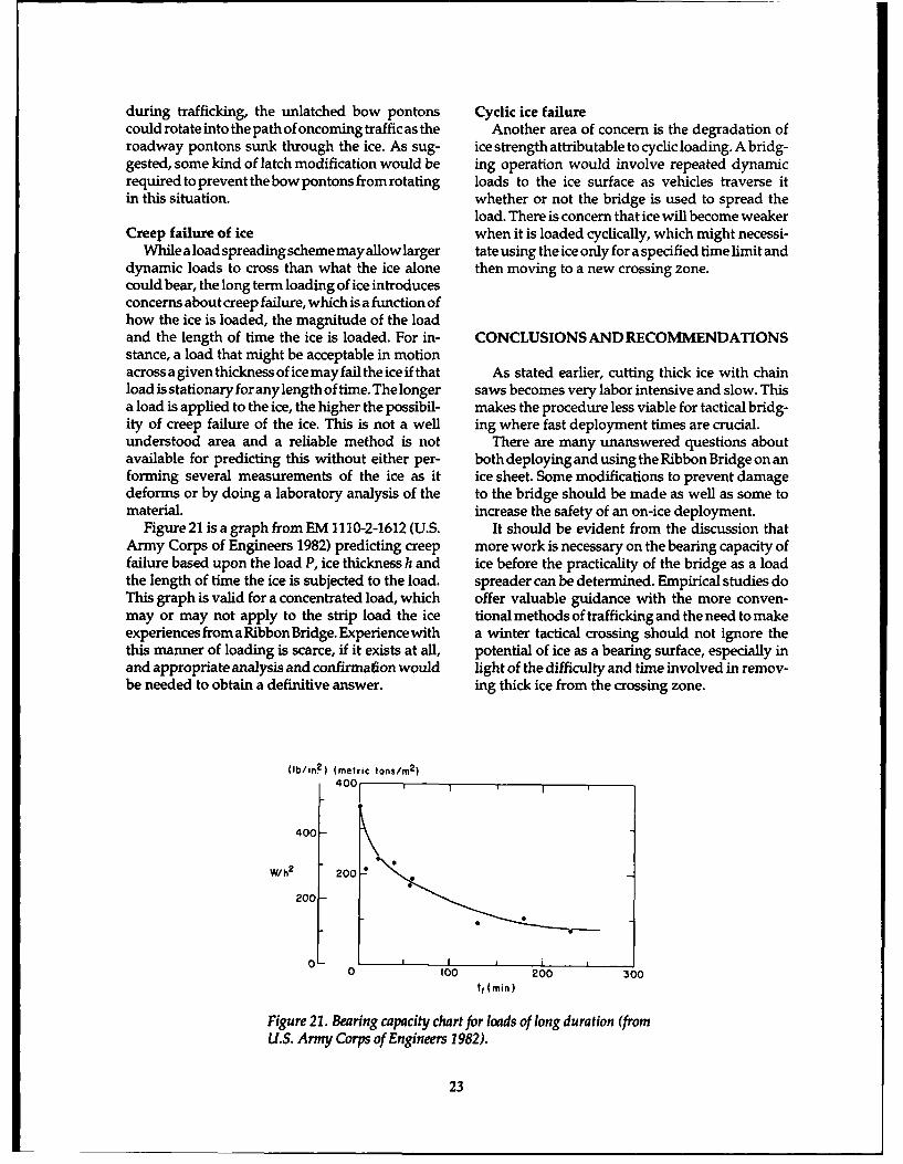
While a load spreading scheme may allow larger tate using the ice only for a specified time limit anddynamic loads to cross than what the ice alone then moving to a new crossing zone.could bear, the long term loading of ice introducesconcerns about creep failure, which is a function ofhow the ice is loaded, the magnitude of the loadand the length of time the ice is loaded. For in- CONCLUSIONS AND RECOMMENDATIONSstance, a load that might be acceptable in motionacross a given thickness of ice may fail the ice if that As stated earlier, cutting thick ice with chainload is stationary for any length of time. The longer saws becomes very labor intensive and slow. Thisa load is applied to the ice, the higher the possibil- makes the procedure less viable for tactical bridg-ity of creep failure of the ice. This is not a well ing where fast deployment times are crucial.understood area and a reliable method is not There are many unanswered questions aboutavailable for predicting this without either per- both deploying and using the Ribbon Bridge on anforming several measurements of the ice as it ice sheet. Some modifications to prevent damagedeforms or by doing a laboratory analysis of the to the bridge should be made as well as some tomaterial. increase the safety of an on-ice deployment.
Figure 21 is a graph from EM 1110-2-1612 (U.S. It should be evident from the discussion thatArmy Corps of Engineers 1982) predicting creep more work is necessary on the bearing capacity offailure based upon the load P, ice thickness h and ice before the practicality of the bridge as a loadthe length of time the ice is subjected to the load. spreader can be determined. Empirical studies doThis graph is valid for a concentrated load, which offer valuable guidance with the more conven-may or may not apply to the strip load the ice tional methods of trafficking and the need to makeexperiences from a Ribbon Bridge. Experience with a winter tactical crossing should not ignore thethis manner of loading is scarce, if it exists at all, potential of ice as a bearing surface, especially inand appropriate analysis and confirmaion would light of the difficulty and time involved in remov-be needed to obtain a definitive answer. ing thick ice from the crossing zone.
(b/in2 ) (metric tons/m 2
)
400 1
400-
W/h2 200
200
0
I 100 200 300
tf (min)
Figure 21. Bearing capacity chart for loads of long duration (fromU.S. Army Corps of Engineers 1982).
23
LITERATURE CITED floating bridges in ice-covered rivers. USA ColdRegions Research and Engineering Laboratory,
Coutermarsh, B. (1987) Tactical bridging during Special Report 88-20. ADB 129 184L.winter. 1986 Korean bridging exercise. USA Cold Stubstad, J, J. Rand and L. Jackson (1984) Opera-Regions Research and Engineering Laboratory, tion of the U.S. Combat Support Boat (USCSB MKSpecial Report 87-13. ADB 114 800L. 1) on an ice-covered waterway. USA Cold RegionsCoutermarsh, B. (1989) Factors affecting rates of Research and Engineering Laboratory, Specialice cutting with a chain saw. USA Cold Regions Report 84-5. ADA 142 535.Research and Engineering Laboratory, Special U.S. Army Corps of Engineers (1982) Ice engineer-Report 89-24. ADA 212 405. ing. EM 1110-2-1612.Hutchinson, A.R.E. (1977) ReportonRibbonBridge U.S. Army (1980) Operator and organizationalice trials (unpublished). FE-BR 1. maintenance manual: Improved float bridge TMMellor, M. and D. Calkins (1988) Deployment of 5-5420-209-12.
24
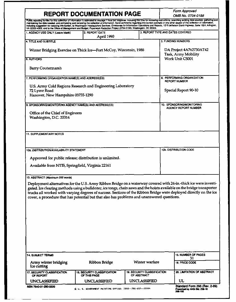
Form ApprovedREPORT DOCUMENTATION PAGE OMB No. o7o4-o188Public reporting burden for this collection of Information is estimated to average I hour per response, incuing the firme for reviewing instructions. searching existing data sources, gathenng andmaintaining the data needed, and completing and reviewing the collection of information. Send comments regarding this burden estimate or any other aspect of this collection of information.Including suggestion for redudng this burden. to Washington Headquarters Services. Directorate for Information Operations and Reports. 1215 Jefferson Davis Highway, Suite 1204. Arington.VA 22202-4302. and to the Office of Management and Budget. Paperwork Reduction Project (0704-0188). Washington. DC 20503.
1. AGENCY USE ONLY (Leave blank) 2. REPORT DATE 3. REPORT TYPE AND DATES COVEREDApril 1990 1
4. TITLE AND SUBTITLE 5. FUNDING NUMBERS
Winter Bridging Exercise on Thick Ice-Fort McCoy, Wisconsin, 1988 DA Project 4A762730AT42Task, Army Mobility
6. AUTHORS Work Unit CS001
Barry Coutermarsh
7. PERFORMING ORGANIZATION NAME(S) AND ADDRESS(ES) 8. PERFORMING ORGANIZATIONREPORT NUMBER
U.S. Army Cold Regions Research and Engineering Laboratory72 Lyme Road Special Report 90-10Hanover, New Hampshire 03755-1290
9. SPONSORING/MONITORING AGENCY NAME(S) AND ADDRESS(ES) 10. SPONSORING/MONITORINGAGENCY REPORT NUMBER
Office of the Chief of EngineersWashington, D.C. 20314
11. SUPPLEMENTARY NOTES
12a. DISTRIBUTION/AVAILABILITY STATEMENT 12b. DISTRIBUTION CODE
Approved for public release; distribution is unlimited.
Available from NTIS, Springfield, Virginia 22161
13. ABSTRACT (Maximum 200 words)
Deployment alternatives for the U.S. Army Ribbon Bridge on a waterway covered with 24-in.-thick ice were investi-gated. Ice clearing methods using a bulldozer, ice tongs, chain saws and the hoists available on the bridge transportertrucks all worked with varying degrees of success. Sections of the Ribbon Bridge were deployed directly on the icecover, a procedure that has potential but that also has problems and unanswered questions.
14. SUBJECT TERMS 15. NUMBER OF PAGES31
Army winter bridging Ribbon Bridge Winter warfare 16. PRICE CODEIce cutting
17. SECURITY CLASSIFICATION 18. SECURITY CLASSIFICATION 19. SECURITY CLASSIFICATION 20. LIMITATION OF ABSTRACTOF REPORT OF THIS PAGE OF ABSTRACT
UNCLASSIFIED UNCLASSIFIED UNCLASSIFIED UL
NSN 7540.01-280-5500 Standard Form 298 (Rev. 2-89)'A U. S. GOVERNIENT PRINTING OFFICE: 19g0--70t-057--22004 PmeeabedbyANSI.Z-18
2gB-to2


![Exer 1 Article 2[1]](https://img.pdfslide.us/doc/110x75/577d36191a28ab3a6b922b8d/exer-1-article-21.jpg)


![Exer 1 Article 3[1]](https://img.pdfslide.us/doc/110x75/577d36191a28ab3a6b922b91/exer-1-article-31.jpg)

![Exer 1 Article 1[1]](https://img.pdfslide.us/doc/110x75/577d36191a28ab3a6b922b8b/exer-1-article-11.jpg)