Embed Size (px)
Citation preview
15370 Barranca Parkway Irvine, CA 92618-2215 USA
DTC1000/DTC4000 User Guide
P/N: L001398, Revision 1.3
© 2011 HID Global Corporation All rights reserved
DTC1000/DTC4000 Card Printer/Encoder User Guide (Rev. 1.3), © 2011 property of HID Global Corporation. All rights reserved.
Exclusive permission is granted to authorized resellers of HID Global products to reproduce and distribute this copyrighted document to authorized HID Global customers, who have signed a no disclosure agreement regarding the restricted, proprietary use of said document.
The revision number for this document will be updated to reflect changes, corrections, updates and enhancements to this document.
Revision Control Number
Date Document Title
Revision 1.3 January 2011 DTC1000/DTC4000
Card Printer/Encoder User Guide
Revision 1.2 August 2010 DTC1000/DTC4000
Card Printer/Encoder User Guide
Trademarks and Disclaimers
HID, HID Global, and Fargo are the trademarks or registered trademarks of HID Global Corporation in the U.S. and other countries.
The information contained in this document is provided AS IS without any warranty.
HID Global hereby disclaims all warranties and conditions with regard to the information contained herein, including all implied warranties of merchantability, fitness for a particular purpose, title and non-infringement.
In no event shall HID Global be liable, whether in contract, tort or otherwise for any indirect, special or consequential damages arising from the use of the information contained in this document.
Any questions regarding changes, corrections, updates or enhancements to this document should be forwarded to:
Hid Global Support Services 6533 Flying Cloud Drive Eden Prairie, MN 55344 (USA) (866) 607-7339 Ext #6 FAX: (952) 946-8492 www.hidglobal.com
DTC1000/DTC4000 Card Printer/Encoder User Guide (L001398, Revision 1.3) 2
© 2011 HID Global Corporation All rights reserved
Table of Contents
DTC1000/DTC4000 User Guide _____________________________________________________________ 1 Section 1: Specifications___________________________________________________________________ 5
Regulatory Compliances ___________________________________________________________________________ 5 Agency Listings__________________________________________________________________________________ 6
United States__________________________________________________________________________________ 6 Canada ______________________________________________________________________________________ 6
Environmental Protection (China-RoHS) ______________________________________________________________ 7 Traditional Chinese RF Emissions and Safety Statements _______________________________________________ 7 Simplified Chinese _____________________________________________________________________________ 8
Safety Messages (review carefully)___________________________________________________________________ 9 Technical Specifications __________________________________________________________________________ 10 Functional Specifications__________________________________________________________________________ 14
Printer Components: Print Ribbons _______________________________________________________________ 14 Ribbon Types/Count Table ________________________________________________________________________ 15
Printer Components: Blank Cards ________________________________________________________________ 16 Section 2: Setup and Installation Procedures _________________________________________________ 17
Choosing a Good Location ________________________________________________________________________ 17 About Moisture Condensation ___________________________________________________________________ 17 Unpacking and Inspection_______________________________________________________________________ 17
Installing the Print Ribbon Cartridge (DTC1000 and DTC4000) ___________________________________________ 18 Installing the Ribbon___________________________________________________________________________ 19
Installing Blank Cards into the Card Hopper (DTC1000 and DTC4000) _____________________________________ 21 Setting the Card Size for CR79 and CR80 __________________________________________________________ 23 Connecting the Printer power ____________________________________________________________________ 27
Section 3: Print Driver Installation _________________________________________________________ 28 Driver Installation Instructions _____________________________________________________________________ 29 Swift ID Installation Instructions____________________________________________________________________ 31 Installing Swift ID _______________________________________________________________________________ 33
Printer Installed On Network ____________________________________________________________________ 34 Printer Connected Via USB Connection ______________________________________________________________ 36
Option No. 1 _________________________________________________________________________________ 36 Option No. 2 _________________________________________________________________________________ 36 Uninstalling Swift ID __________________________________________________________________________ 37 Additional Swift ID Rules ______________________________________________________________________ 37
Section 4: Printer Preferences Tab Functions ________________________________________________ 38 Using the Card tab _______________________________________________________________________________ 38 Using the Toolbox Options ________________________________________________________________________ 40
Using the Configuration tab _____________________________________________________________________ 41 Using the Event Monitoring Group Box____________________________________________________________ 41 Using the Calibrate Ribbon tab___________________________________________________________________ 42 Using the Clean Printer tab______________________________________________________________________ 43 Using the Advanced Settings tab _________________________________________________________________ 45
Using the Device Options tab ______________________________________________________________________ 54 Using the Image Color tab_________________________________________________________________________ 58 Using the Image Calibrate tab ______________________________________________________________________ 61 Using the Magnetic Encoding Tab __________________________________________________________________ 62
DTC1000/DTC4000 Card Printer/Encoder User Guide (L001398, Revision 1.3) 3
© 2011 HID Global Corporation All rights reserved
Using the Magnetic Encoding Tab – ISO Standards___________________________________________________ 63 Using the Magnetic Encoding Tab – Custom Encoding or Raw Binary Encoding Mode ______________________ 65 Reviewing the ISO Track Locations_______________________________________________________________ 66 Reviewing the Sample String ____________________________________________________________________ 67 Sending the Track Information ___________________________________________________________________ 68 Reviewing the ASCII Code and Character Table _____________________________________________________ 69
Using the Overlay / Print Area tab___________________________________________________________________ 71 Using the K Panel Resin tab _______________________________________________________________________ 74 Using the Printer Info tab _________________________________________________________________________ 77
Section 5: Selecting the Fluorescent Panel Ribbon Type (DTC4000 only) __________________________ 78 Creating a Custom Fluorescent Image (using the YMCFKO Ribbon) _______________________________________ 78 Configuring Fluorescent Data (F-Panel for YMCFKO Ribbon) using the Application __________________________ 80
Section 6: System Overview- Troubleshooting ________________________________________________ 84 Reviewing the DTC1000/DTC4000 Sequence of Operations ______________________________________________ 84
Section 7: Troubleshooting ________________________________________________________________ 86 Printer Error Button and Display Message Table _______________________________________________________ 86 Using the Error Message Table _____________________________________________________________________ 88 Troubleshooting with the Error Message Table_________________________________________________________ 89 Printer Specific Tools (DTC1000/DTC4000) __________________________________________________________ 97
Additional Printer Specific Tools (DTC4000) _______________________________ Error! Bookmark not defined. Section 8: Cleaning _____________________________________________________________________ 101
Safety Messages (review carefully)_________________________________________________________________ 101 DTC1000 and DTC4000 Card Printer/Encoders Cleaning Kit ____________________________________________ 102
Supplies (included with the Cleaning Kit) _________________________________________________________ 102 Printhead Cleaning _____________________________________________________________________________ 103
Cleaning the Platen and the Card Feed Rollers______________________________________________________ 104 Cleaning the Printer’s Interior _____________________________________________________________________ 108 Cleaning the Printer’s Exterior ____________________________________________________________________ 108
Section 9: Firmware Upgrades____________________________________________________________ 109 Upgrade the Printer Firmware _____________________________________________________________________ 109
Section 10: HID Global Technical Support__________________________________________________ 112 Reading the Serial Numbers on a Fargo Printer _______________________________________________________ 113
Appendix A ____________________________________________________________________________ 114 Using the Defined Area Option ____________________________________________________________________ 114 Configuring Fluorescent Data (F-Panel for YMCFKO Ribbon) using the Workbench _________________________ 115
DTC1000/DTC4000 Card Printer/Encoder User Guide (L001398, Revision 1.3) 4
© 2011 HID Global Corporation All rights reserved
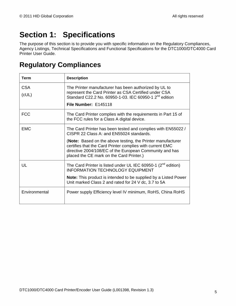
Section 1: Specifications The purpose of this section is to provide you with specific information on the Regulatory Compliances, Agency Listings, Technical Specifications and Functional Specifications for the DTC1000/DTC4000 Card Printer User Guide.
Regulatory Compliances
Term Description
CSA
(cUL)
The Printer manufacturer has been authorized by UL to represent the Card Printer as CSA Certified under CSA Standard C22.2 No. 60950-1-03. IEC 60950-1 2nd edition
File Number: E145118
FCC The Card Printer complies with the requirements in Part 15 of the FCC rules for a Class A digital device.
EMC The Card Printer has been tested and complies with EN55022 / CISPR 22 Class A: and EN55024 standards.
(Note: Based on the above testing, the Printer manufacturer certifies that the Card Printer complies with current EMC directive 2004/108/EC of the European Community and has placed the CE mark on the Card Printer.)
UL The Card Printer is listed under UL IEC 60950-1 (2nd edition) INFORMATION TECHNOLOGY EQUIPMENT
Note: This product is intended to be supplied by a Listed Power Unit marked Class 2 and rated for 24 V dc, 3.7 to 5A
Environmental Power supply Efficiency level IV minimum, RoHS, China RoHS
DTC1000/DTC4000 Card Printer/Encoder User Guide (L001398, Revision 1.3) 5
© 2011 HID Global Corporation All rights reserved
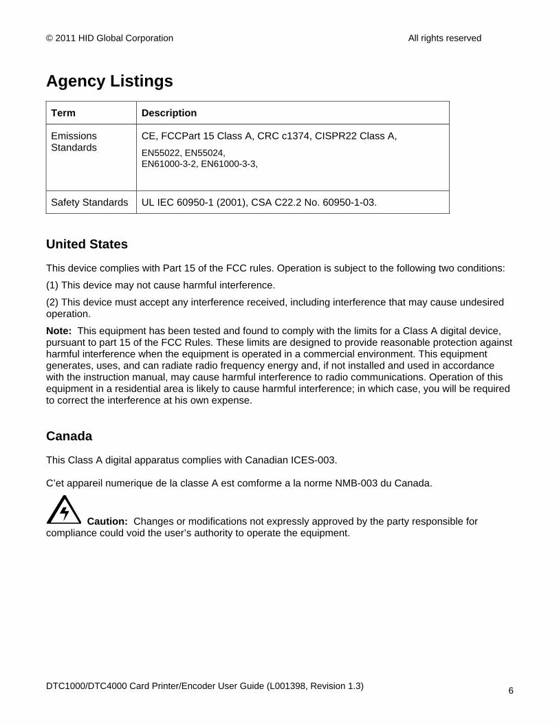
Agency Listings
Term Description
Emissions Standards
CE, FCCPart 15 Class A, CRC c1374, CISPR22 Class A, EN55022, EN55024, EN61000-3-2, EN61000-3-3,
Safety Standards UL IEC 60950-1 (2001), CSA C22.2 No. 60950-1-03.
United States
This device complies with Part 15 of the FCC rules. Operation is subject to the following two conditions:
(1) This device may not cause harmful interference.
(2) This device must accept any interference received, including interference that may cause undesired operation.
Note: This equipment has been tested and found to comply with the limits for a Class A digital device, pursuant to part 15 of the FCC Rules. These limits are designed to provide reasonable protection against harmful interference when the equipment is operated in a commercial environment. This equipment generates, uses, and can radiate radio frequency energy and, if not installed and used in accordance with the instruction manual, may cause harmful interference to radio communications. Operation of this equipment in a residential area is likely to cause harmful interference; in which case, you will be required to correct the interference at his own expense.
Canada
This Class A digital apparatus complies with Canadian ICES-003. C’et appareil numerique de la classe A est comforme a la norme NMB-003 du Canada.
Caution: Changes or modifications not expressly approved by the party responsible for compliance could void the user’s authority to operate the equipment.
DTC1000/DTC4000 Card Printer/Encoder User Guide (L001398, Revision 1.3) 6
© 2011 HID Global Corporation All rights reserved
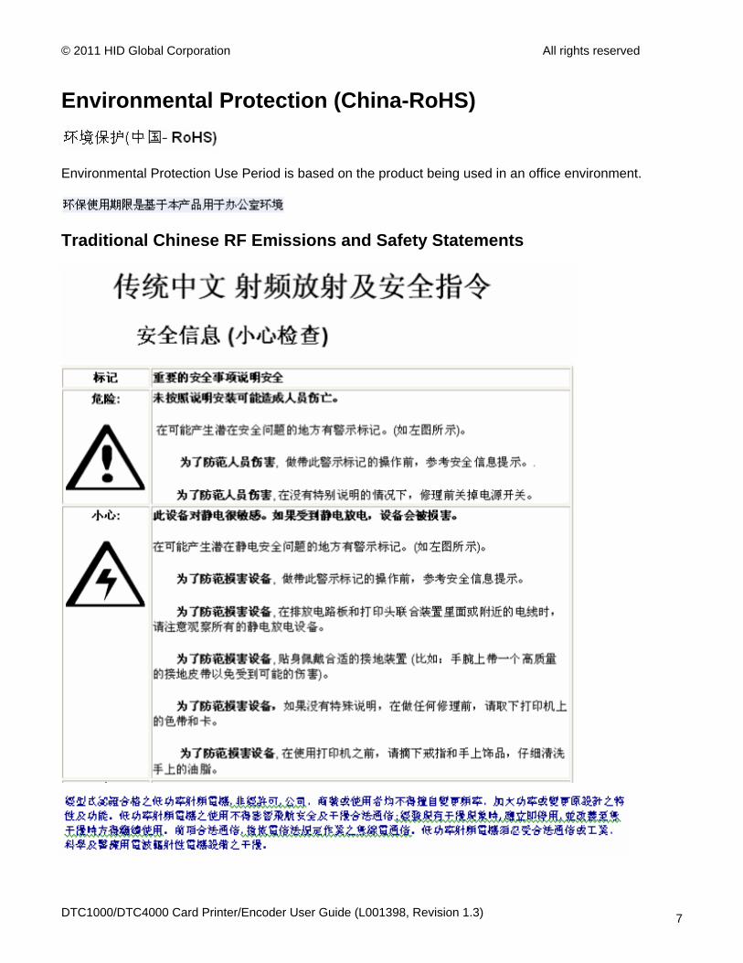
Environmental Protection (China-RoHS)
Environmental Protection Use Period is based on the product being used in an office environment.
Traditional Chinese RF Emissions and Safety Statements
DTC1000/DTC4000 Card Printer/Encoder User Guide (L001398, Revision 1.3) 7
© 2011 HID Global Corporation All rights reserved
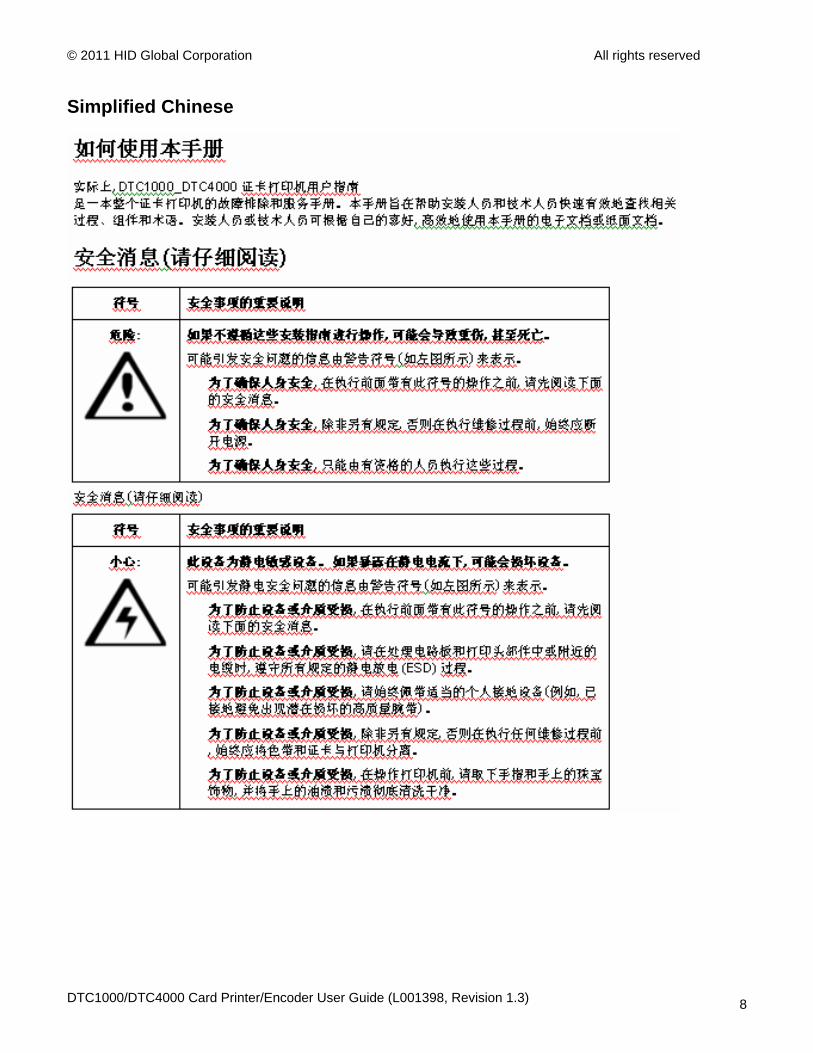
Simplified Chinese
DTC1000/DTC4000 Card Printer/Encoder User Guide (L001398, Revision 1.3) 8
© 2011 HID Global Corporation All rights reserved
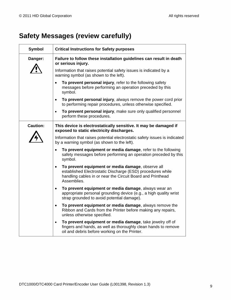
Safety Messages (review carefully)
Symbol Critical Instructions for Safety purposes
Danger:
Failure to follow these installation guidelines can result in death or serious injury. Information that raises potential safety issues is indicated by a warning symbol (as shown to the left).
• To prevent personal injury, refer to the following safety messages before performing an operation preceded by this symbol.
• To prevent personal injury, always remove the power cord prior to performing repair procedures, unless otherwise specified.
• To prevent personal injury, make sure only qualified personnel perform these procedures.
Caution:
This device is electrostatically sensitive. It may be damaged if exposed to static electricity discharges. Information that raises potential electrostatic safety issues is indicated by a warning symbol (as shown to the left).
• To prevent equipment or media damage, refer to the following safety messages before performing an operation preceded by this symbol.
• To prevent equipment or media damage, observe all established Electrostatic Discharge (ESD) procedures while handling cables in or near the Circuit Board and Printhead Assemblies.
• To prevent equipment or media damage, always wear an appropriate personal grounding device (e.g., a high quality wrist strap grounded to avoid potential damage).
• To prevent equipment or media damage, always remove the Ribbon and Cards from the Printer before making any repairs, unless otherwise specified.
• To prevent equipment or media damage, take jewelry off of fingers and hands, as well as thoroughly clean hands to remove oil and debris before working on the Printer.
DTC1000/DTC4000 Card Printer/Encoder User Guide (L001398, Revision 1.3) 9
© 2011 HID Global Corporation All rights reserved
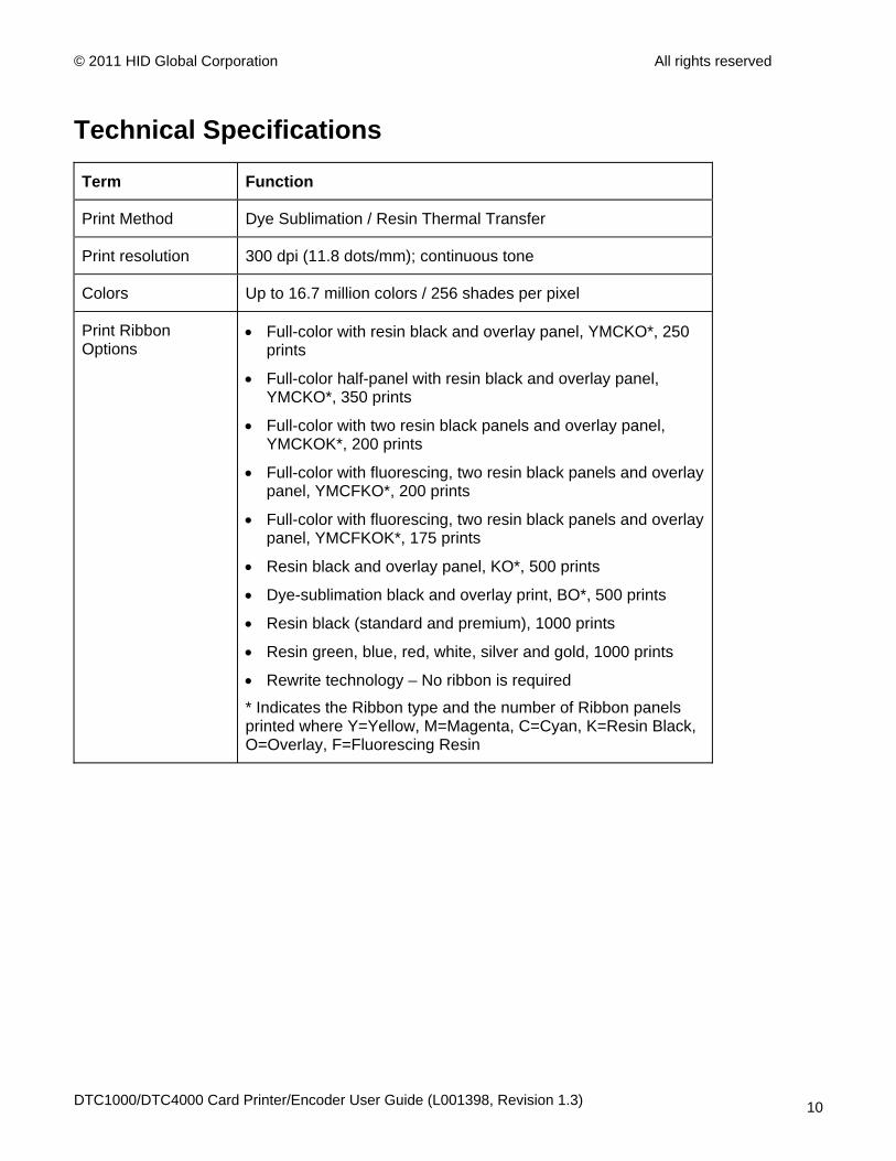
Technical Specifications
Term Function
Print Method Dye Sublimation / Resin Thermal Transfer
Print resolution 300 dpi (11.8 dots/mm); continuous tone
Colors Up to 16.7 million colors / 256 shades per pixel
Print Ribbon Options
• Full-color with resin black and overlay panel, YMCKO*, 250 prints
• Full-color half-panel with resin black and overlay panel, YMCKO*, 350 prints
• Full-color with two resin black panels and overlay panel, YMCKOK*, 200 prints
• Full-color with fluorescing, two resin black panels and overlay panel, YMCFKO*, 200 prints
• Full-color with fluorescing, two resin black panels and overlay panel, YMCFKOK*, 175 prints
• Resin black and overlay panel, KO*, 500 prints
• Dye-sublimation black and overlay print, BO*, 500 prints
• Resin black (standard and premium), 1000 prints
• Resin green, blue, red, white, silver and gold, 1000 prints
• Rewrite technology – No ribbon is required
* Indicates the Ribbon type and the number of Ribbon panels printed where Y=Yellow, M=Magenta, C=Cyan, K=Resin Black, O=Overlay, F=Fluorescing Resin
DTC1000/DTC4000 Card Printer/Encoder User Guide (L001398, Revision 1.3) 10
© 2011 HID Global Corporation All rights reserved
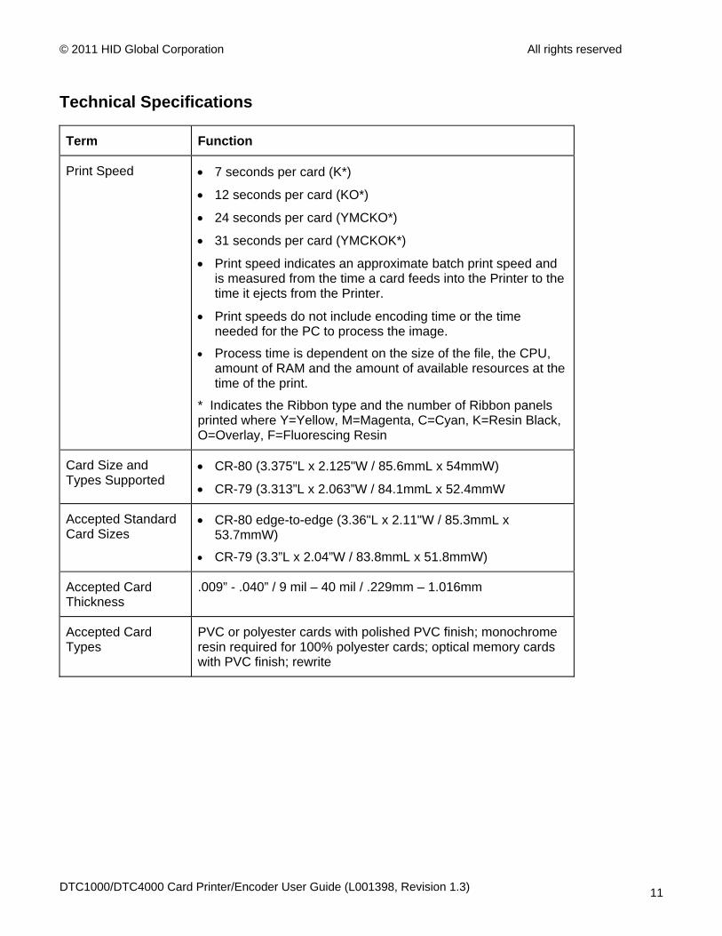
Technical Specifications
Term Function
Print Speed • 7 seconds per card (K*)
• 12 seconds per card (KO*)
• 24 seconds per card (YMCKO*)
• 31 seconds per card (YMCKOK*)
• Print speed indicates an approximate batch print speed and is measured from the time a card feeds into the Printer to the time it ejects from the Printer.
• Print speeds do not include encoding time or the time needed for the PC to process the image.
• Process time is dependent on the size of the file, the CPU, amount of RAM and the amount of available resources at the time of the print.
* Indicates the Ribbon type and the number of Ribbon panels printed where Y=Yellow, M=Magenta, C=Cyan, K=Resin Black, O=Overlay, F=Fluorescing Resin
Card Size and Types Supported
• CR-80 (3.375"L x 2.125"W / 85.6mmL x 54mmW)
• CR-79 (3.313”L x 2.063”W / 84.1mmL x 52.4mmW
Accepted Standard Card Sizes
• CR-80 edge-to-edge (3.36"L x 2.11"W / 85.3mmL x 53.7mmW)
• CR-79 (3.3”L x 2.04”W / 83.8mmL x 51.8mmW)
Accepted Card Thickness
.009” - .040” / 9 mil – 40 mil / .229mm – 1.016mm
Accepted Card Types
PVC or polyester cards with polished PVC finish; monochrome resin required for 100% polyester cards; optical memory cards with PVC finish; rewrite
DTC1000/DTC4000 Card Printer/Encoder User Guide (L001398, Revision 1.3) 11

© 2011 HID Global Corporation All rights reserved
Technical Specifications
Term Function
Input Hopper Card Capacity
100 cards (.030” / .762.mm) DTC1000, DTC4000
200 cards (.030” / .762 mm) DTC4000 (Dual Hopper)
Output Hopper Card Capacity
100 cards (.030” / .762.mm) DTC4000
30 cards (.030” / .762.mm) DTC1000
Reject Hopper Card Capacity
100 cards (.030” / .762.mm) – same-side Input/Output Card Hopper (required)
Card Cleaning Card cleaning roller integrated into the Ribbon Cartridge.
A new cleaning roller is included with each Ribbon Cartridge.
Printer Memory 32MB RAM
Software Driver Windows® XP / Vista™ (32 bit & 64 bit) / Server 2003 & 2008 / Windows® 7 (32 bit & 64 bit) / Linux®
Interface USB 2.0 and Ethernet with internal print server
Operating Temperature
65 degrees to 80 degrees F / 18 degrees to 27 degrees C
Humidity 20-80% non-condensing
Dimensions Here are the dimensions for the DTC1000:
• Single-Sided Printer: 8.8˝H x 13.7˝W x 7.9˝D / 224mmH x 348mmW x 201mmD
• Dual-Sided Printer: 9.8˝H x 18.7˝W x 9.2˝D / 249mmH x 475mmW x 234mmD
Here are the dimensions for the DTC4000:
• Single-Sided Printer: 9.8˝H x 18.1˝W x 9.2˝D / 249mmH x 460mmW x 234mmD
• Dual-Sided Printer: 9.8˝H x 18.7˝W x 9.2˝D / 249mmH x 475mmW x 234mmD
Weight Single-Sided: 8 lbs. / 3.63 Kg; Dual-Sided: 10 lbs. / 4.54 Kg
Agency Listings Safety: UL 60950-1, CSA C22.2 (60950-1), and CE; EMC; FCC Class A, CRC c1374, CE (EN 55022 Class A, EN 55024), CCC, BSMI, KCC
DTC1000/DTC4000 Card Printer/Encoder User Guide (L001398, Revision 1.3) 12
© 2011 HID Global Corporation All rights reserved
Technical Specifications
Term Function
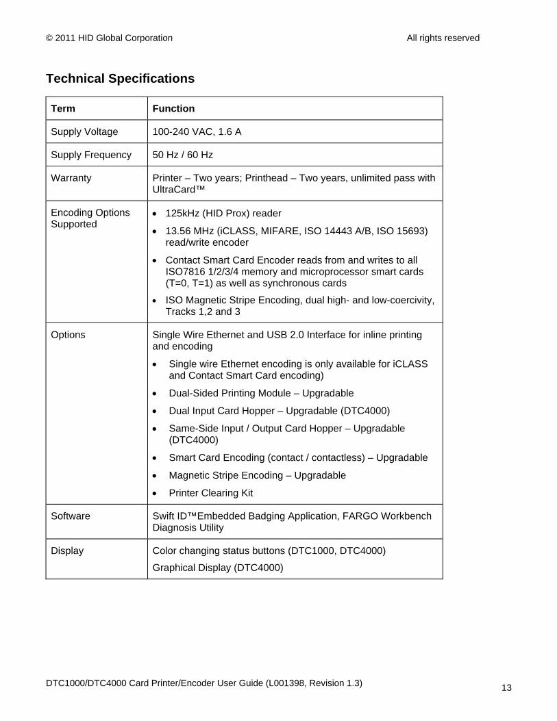
Supply Voltage 100-240 VAC, 1.6 A
Supply Frequency 50 Hz / 60 Hz
Warranty Printer – Two years; Printhead – Two years, unlimited pass with UltraCard™
Encoding Options Supported
• 125kHz (HID Prox) reader
• 13.56 MHz (iCLASS, MIFARE, ISO 14443 A/B, ISO 15693) read/write encoder
• Contact Smart Card Encoder reads from and writes to all ISO7816 1/2/3/4 memory and microprocessor smart cards (T=0, T=1) as well as synchronous cards
• ISO Magnetic Stripe Encoding, dual high- and low-coercivity, Tracks 1,2 and 3
Options Single Wire Ethernet and USB 2.0 Interface for inline printing and encoding
• Single wire Ethernet encoding is only available for iCLASS and Contact Smart Card encoding)
• Dual-Sided Printing Module – Upgradable
• Dual Input Card Hopper – Upgradable (DTC4000)
• Same-Side Input / Output Card Hopper – Upgradable (DTC4000)
• Smart Card Encoding (contact / contactless) – Upgradable
• Magnetic Stripe Encoding – Upgradable
• Printer Clearing Kit
Software Swift ID™Embedded Badging Application, FARGO Workbench Diagnosis Utility
Display Color changing status buttons (DTC1000, DTC4000)
Graphical Display (DTC4000)
DTC1000/DTC4000 Card Printer/Encoder User Guide (L001398, Revision 1.3) 13
© 2011 HID Global Corporation All rights reserved
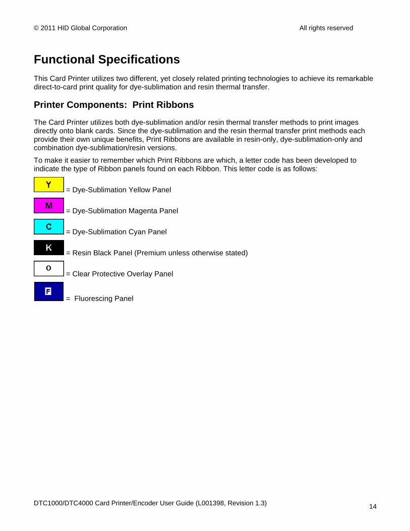
Functional Specifications This Card Printer utilizes two different, yet closely related printing technologies to achieve its remarkable direct-to-card print quality for dye-sublimation and resin thermal transfer.
Printer Components: Print Ribbons
The Card Printer utilizes both dye-sublimation and/or resin thermal transfer methods to print images directly onto blank cards. Since the dye-sublimation and the resin thermal transfer print methods each provide their own unique benefits, Print Ribbons are available in resin-only, dye-sublimation-only and combination dye-sublimation/resin versions.
To make it easier to remember which Print Ribbons are which, a letter code has been developed to indicate the type of Ribbon panels found on each Ribbon. This letter code is as follows:
= Dye-Sublimation Yellow Panel
= Dye-Sublimation Magenta Panel
= Dye-Sublimation Cyan Panel
= Resin Black Panel (Premium unless otherwise stated)
= Clear Protective Overlay Panel
= Fluorescing Panel
DTC1000/DTC4000 Card Printer/Encoder User Guide (L001398, Revision 1.3) 14

© 2011 HID Global Corporation All rights reserved
Ribbon Types/Count Table Ribbon type and count used in each Printer.
Ribbon DTC1000 DTC4000
YMCKO – Full Color/Resin Black/Overlay
250 250
YMCKO Half Panel – Full Color (1/2)/Resin Black/Overlay
350 350
YMCFKO - Full Color/UV Fluorescing/Resin Black/Overlay
200
YMCKK - Full Color/2 Resin Black
YMCKOK - Full Color/2 Resin Black/Overlay
200 200
YMCFKOK - Full Color/UV Fluorescing/2 Resin Black/Overlay
175
K – Standard Resin 1000 1000
K – Premium Resin 1000 1000
Colored Resin 1000 1000
KO - Premium Black Resin/Overlay
500 500
BO - Dye-Sub Black/Overlay 500 500
None – Rewritable Supported Supported
DTC1000/DTC4000 Card Printer/Encoder User Guide (L001398, Revision 1.3) 15
© 2011 HID Global Corporation All rights reserved
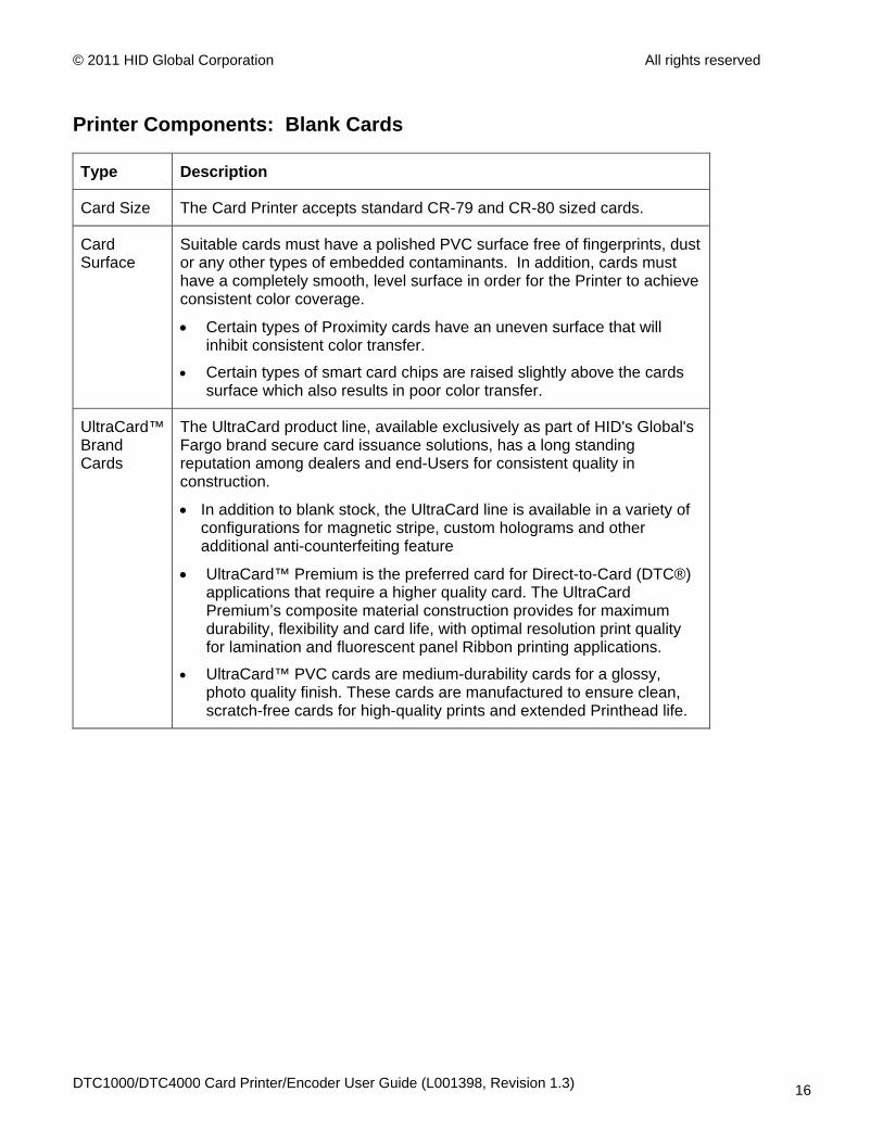
Printer Components: Blank Cards
Type Description
Card Size The Card Printer accepts standard CR-79 and CR-80 sized cards.
Card Surface
Suitable cards must have a polished PVC surface free of fingerprints, dust or any other types of embedded contaminants. In addition, cards must have a completely smooth, level surface in order for the Printer to achieve consistent color coverage.
• Certain types of Proximity cards have an uneven surface that will inhibit consistent color transfer.
• Certain types of smart card chips are raised slightly above the cards surface which also results in poor color transfer.
UltraCard™ Brand Cards
The UltraCard product line, available exclusively as part of HID's Global's Fargo brand secure card issuance solutions, has a long standing reputation among dealers and end-Users for consistent quality in construction.
• In addition to blank stock, the UltraCard line is available in a variety of configurations for magnetic stripe, custom holograms and other additional anti-counterfeiting feature
• UltraCard™ Premium is the preferred card for Direct-to-Card (DTC®) applications that require a higher quality card. The UltraCard Premium’s composite material construction provides for maximum durability, flexibility and card life, with optimal resolution print quality for lamination and fluorescent panel Ribbon printing applications.
• UltraCard™ PVC cards are medium-durability cards for a glossy, photo quality finish. These cards are manufactured to ensure clean, scratch-free cards for high-quality prints and extended Printhead life.
DTC1000/DTC4000 Card Printer/Encoder User Guide (L001398, Revision 1.3) 16
© 2011 HID Global Corporation All rights reserved
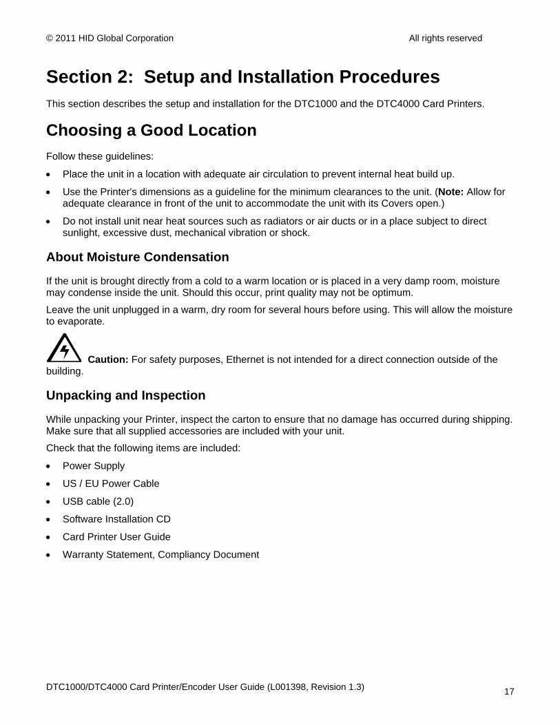
Section 2: Setup and Installation Procedures This section describes the setup and installation for the DTC1000 and the DTC4000 Card Printers.
Choosing a Good Location Follow these guidelines:
• Place the unit in a location with adequate air circulation to prevent internal heat build up.
• Use the Printer's dimensions as a guideline for the minimum clearances to the unit. (Note: Allow for adequate clearance in front of the unit to accommodate the unit with its Covers open.)
• Do not install unit near heat sources such as radiators or air ducts or in a place subject to direct sunlight, excessive dust, mechanical vibration or shock.
About Moisture Condensation
If the unit is brought directly from a cold to a warm location or is placed in a very damp room, moisture may condense inside the unit. Should this occur, print quality may not be optimum.
Leave the unit unplugged in a warm, dry room for several hours before using. This will allow the moisture to evaporate.
Caution: For safety purposes, Ethernet is not intended for a direct connection outside of the building.
Unpacking and Inspection
While unpacking your Printer, inspect the carton to ensure that no damage has occurred during shipping. Make sure that all supplied accessories are included with your unit.
Check that the following items are included:
• Power Supply
• US / EU Power Cable
• USB cable (2.0)
• Software Installation CD
• Card Printer User Guide
• Warranty Statement, Compliancy Document
DTC1000/DTC4000 Card Printer/Encoder User Guide (L001398, Revision 1.3) 17
© 2011 HID Global Corporation All rights reserved
Installing the Print Ribbon Cartridge (DTC1000 and DTC4000) Fargo Card Printers requires highly specialized supplies to function properly.
• The Fargo DTC1000 and DTC4000 Card Printers use a one-piece, disposable Ribbon Cartridge load system.
• To maximize Printer life, reliability, printed card quality and durability, you must use only Fargo-certified supplies.
• For this reason, your Fargo warranty is void, where not prohibited by law, if you use non-Fargo-certified supplies.
• Printer cleaning is recommended with each Ribbon change to ensure quality printed cards.
• Resin-only Print Ribbons consist of a continuous roll of a single resin color. No protective overlay panel (O) is provided since resin images do not require the protection of such an overlay.
DTC1000/DTC4000 Card Printer/Encoder User Guide (L001398, Revision 1.3) 18

© 2011 HID Global Corporation All rights reserved
Installing the Ribbon
Step Procedure
1 Insert the Print Ribbon Cartridge into the Printer.
DTC1000
DTC4000 with Flipper Module
DTC1000/DTC4000 Card Printer/Encoder User Guide (L001398, Revision 1.3) 19

© 2011 HID Global Corporation All rights reserved
Installing the Ribbon
Step Procedure
2 Close the Front Cover.
DTC1000
DTC4000 with Flipper Module
DTC1000/DTC4000 Card Printer/Encoder User Guide (L001398, Revision 1.3) 20
© 2011 HID Global Corporation All rights reserved
Installing Blank Cards into the Card Hopper (DTC1000 and DTC4000) The Fargo DTC1000 and DTC4000 Printer is capable of printing single load cards and multiple feed cards (batch mode). To print using single feed, simply remove all cards from the Card Hopper, leave the Card Hopper door closed and place a card in the single Feed Card Slot (which can be used repeatedly).
Step Procedure
1 Pre-instruction. Load the cards with the print side down and (if applicable) the magnetic strip up and towards the front of the Printer.
Caution: Do not run the cards with a contaminated, dull or uneven surface through the Printer.
• Printing onto such cards will ultimately lead to poor print quality and will greatly reduce the life of the Printhead.
• Card Types include PVC or PVC finish.
• Cards eject into the Output Hopper or Reject Hopper.
• Both Hoppers hold 100 cards.
• Certain types of smart card chips are raised slightly above the cards surface, which may result in poor color transfer. Design the card with white space surrounding the chip.
• To print using single feed, simply remove all cards from the Card Hopper, leave the Card Hopper door closed and place a card in the single Feed Card Slot (which can be used repeatedly).
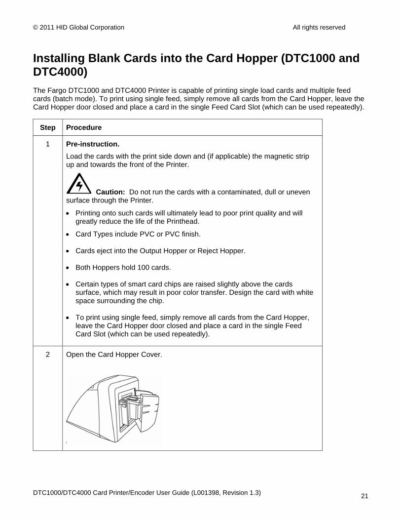
2 Open the Card Hopper Cover.
DTC1000/DTC4000 Card Printer/Encoder User Guide (L001398, Revision 1.3) 21

© 2011 HID Global Corporation All rights reserved
Installing Blank Cards into the Card Hopper (DTC1000 and DTC4000)
Step Procedure
3 Press the Card Hopper Load Lever down until the Card Tray locks into place.
4 a. Load up to 100 cards into the Hopper with the print side down.
b. If using cards with a magnetic stripe, the magnetic stripe should be loaded with the stripe up and to the front of the Printer.
5 Close the Card Hopper Cover to release the lever to the printing position.
DTC1000/DTC4000 Card Printer/Encoder User Guide (L001398, Revision 1.3) 22
© 2011 HID Global Corporation All rights reserved
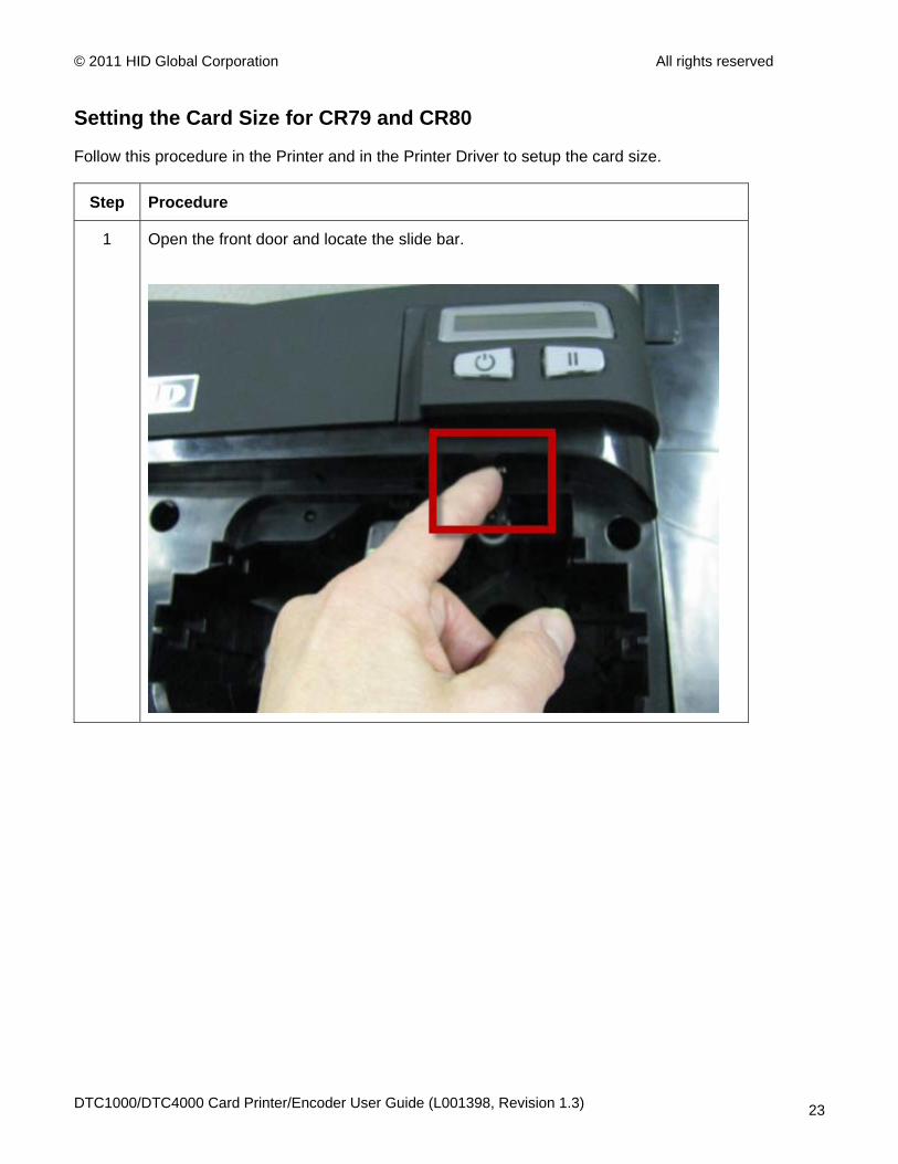
Setting the Card Size for CR79 and CR80
Follow this procedure in the Printer and in the Printer Driver to setup the card size.
Step Procedure
1 Open the front door and locate the slide bar.
DTC1000/DTC4000 Card Printer/Encoder User Guide (L001398, Revision 1.3) 23
© 2011 HID Global Corporation All rights reserved
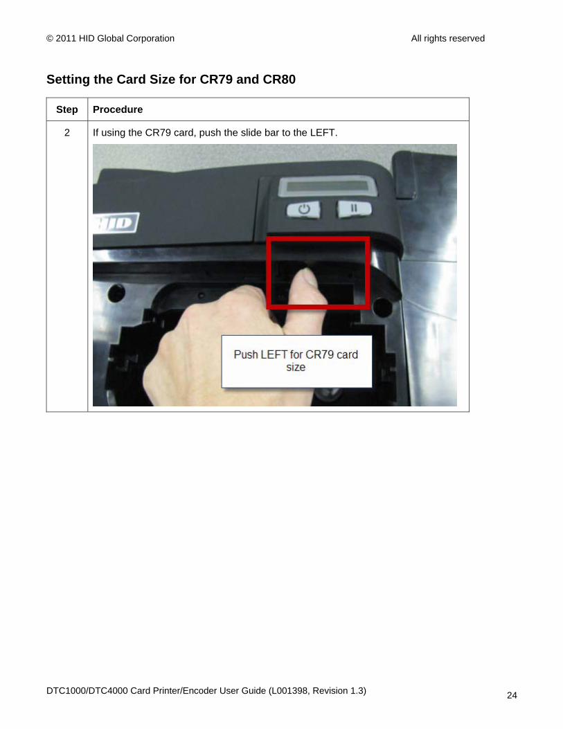
Setting the Card Size for CR79 and CR80
Step Procedure
2 If using the CR79 card, push the slide bar to the LEFT.
DTC1000/DTC4000 Card Printer/Encoder User Guide (L001398, Revision 1.3) 24
© 2011 HID Global Corporation All rights reserved
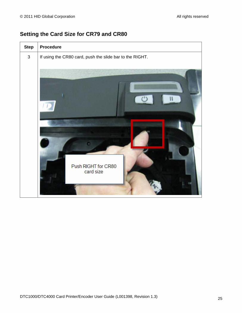
Setting the Card Size for CR79 and CR80
Step Procedure
3 If using the CR80 card, push the slide bar to the RIGHT.
DTC1000/DTC4000 Card Printer/Encoder User Guide (L001398, Revision 1.3) 25
© 2011 HID Global Corporation All rights reserved
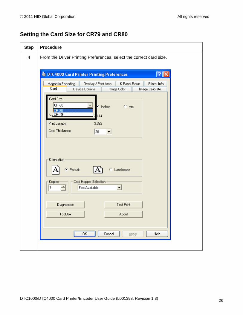
Setting the Card Size for CR79 and CR80
Step Procedure
4 From the Driver Printing Preferences, select the correct card size.
DTC1000/DTC4000 Card Printer/Encoder User Guide (L001398, Revision 1.3) 26
© 2011 HID Global Corporation All rights reserved
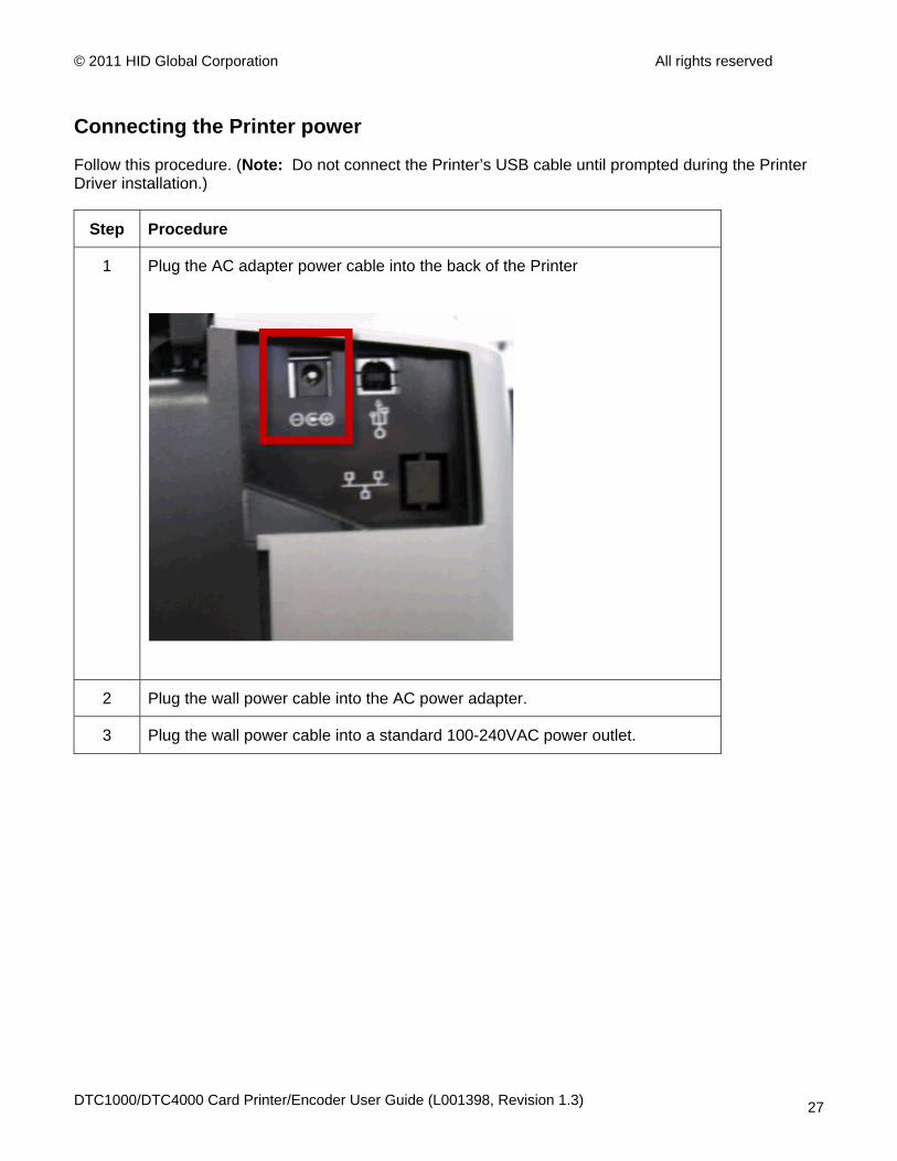
Connecting the Printer power
Follow this procedure. (Note: Do not connect the Printer’s USB cable until prompted during the Printer Driver installation.)
Step Procedure
1 Plug the AC adapter power cable into the back of the Printer
2 Plug the wall power cable into the AC power adapter.
3 Plug the wall power cable into a standard 100-240VAC power outlet.
DTC1000/DTC4000 Card Printer/Encoder User Guide (L001398, Revision 1.3) 27
© 2011 HID Global Corporation All rights reserved
Section 3: Print Driver Installation This section describes the Printer Driver installation requirements and standard procedures. Requirements are listed below. The DTC1000, DTC4000 Print Driver supports the following:
• Windows Vista 32 bit w/SP2
• Windows Vista 64 bit w/SP2
• Windows XP 32 bit w/SP3
• Windows Server 2003 (R1) 32 bit
• Windows Server 2008 (R1) 32 bit w/SP2
• Windows Server 2008 (R1) 64 bit w/SP2
• Windows Server 2008 R2
• Windows 7 32 bit & 64 bit
• Linux OS (Ubuntu7.10, Red Hat Enterprise Desktop 5, Fecora Core 7 & 8, openSUSE 10.3, open NOVELL SUSE 10.) Contact HID/Fargo Technical Support for the Driver.
• For more information on supported operating systems, please visit: www.fargosupport.com
DTC1000/DTC4000 Card Printer/Encoder User Guide (L001398, Revision 1.3) 28
© 2011 HID Global Corporation All rights reserved
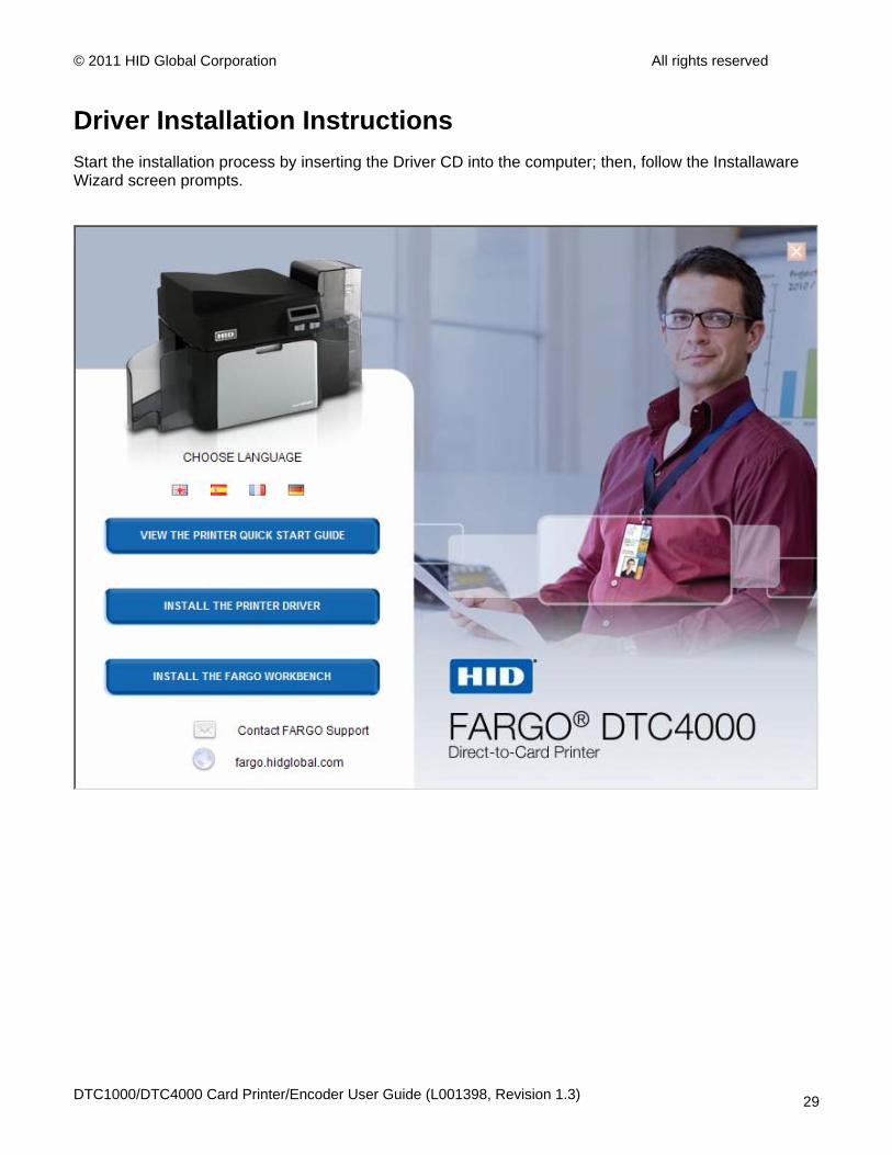
Driver Installation Instructions Start the installation process by inserting the Driver CD into the computer; then, follow the Installaware Wizard screen prompts.
DTC1000/DTC4000 Card Printer/Encoder User Guide (L001398, Revision 1.3) 29
© 2011 HID Global Corporation All rights reserved
Driver Installation Instructions
• Select “Install the Printer Driver” to start the Driver installation.
• Select the Fargo Workbench Utility Program to install the Diagnostic program.
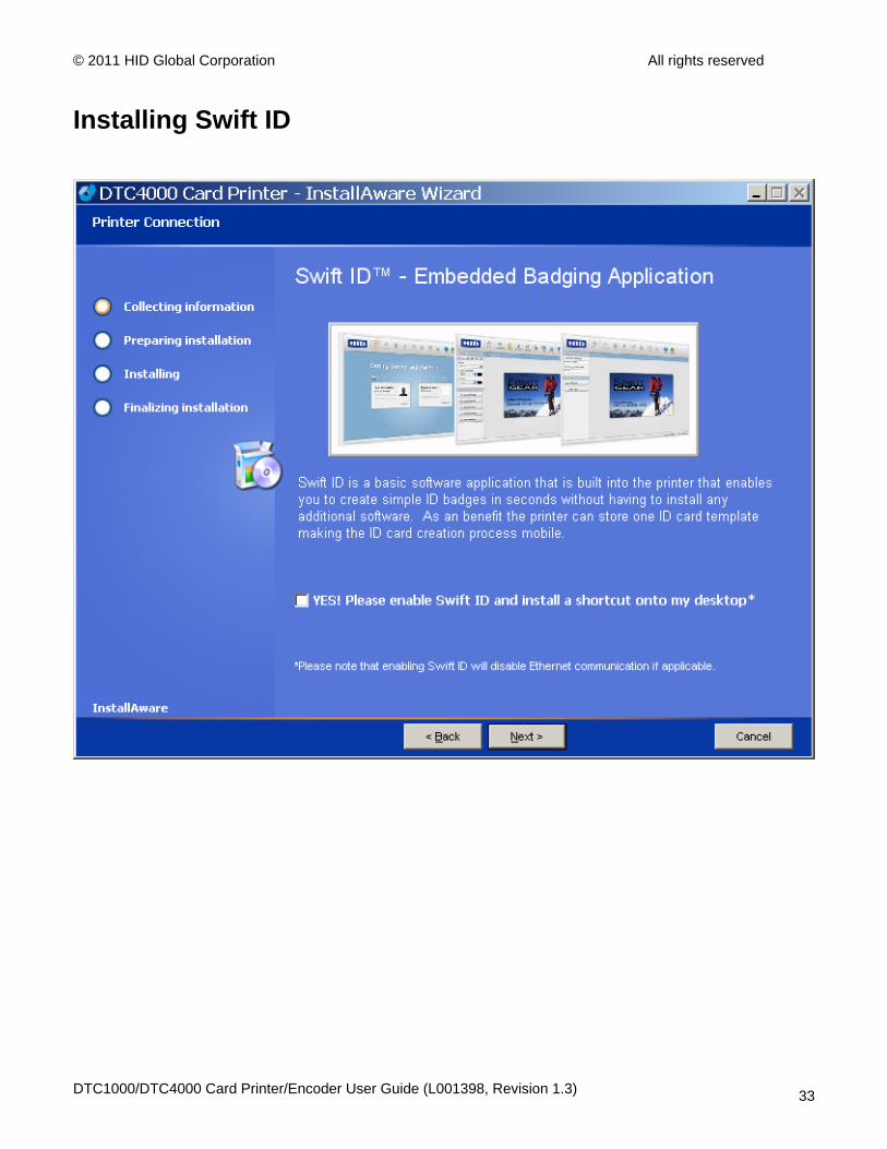
• Select the Swift ID™ to install the Swift ID (Embedded Badging Application software) follow the Installaware Wizard.
• All versions of Windows require Administrator rights.
• From the Printer & Faxes folder, open the Printing Preferences to setup the Driver after it has been installed.
• Printing Preferences need to be setup after the Driver has been installed. Each TAB is shown below.
• Use the drop down arrows to select the correct options for each printing preference.
• Enable Swift ID over a USB connection: This item will be checked if the Printer is setup to utilize Swift ID via a USB connection.
o When this box is checked the Ethernet connection (if applicable) on the Printer will not be operational.
o If this selection is not accessible, this is because the HID EEM Driver that Swift ID uses to connect via a USB connection has not been installed.
o This Driver can be found on the installation CD or it can be down loaded from the HID Global support page.
o The easiest method for enabling Swift ID is to un-install the Printer and its components and go through the installation procedure and select that you would like to use the Swift ID application.
DTC1000/DTC4000 Card Printer/Encoder User Guide (L001398, Revision 1.3) 30
© 2011 HID Global Corporation All rights reserved
Swift ID Installation Instructions Here are the related definitions for the Swift ID installation instructions.
• Swift ID: This is a ‘built-in badging’ application which enables Users to create simple ID badges without having to install any additional software. (Note: This application is only intended for use between one Printer and one PC. The application cannot select between Printers; also, only one Printer on a PC can access Swift ID.)
• HID EEM Driver: This Driver is used by Swift ID to communicate with the PC when connected via a USB cable. (Note: It is also known as an ‘ETHERNET Emulation Module’.)
• EEM Device Flag (i.e., Enable Swift ID over a USB connection): Check this item to utilize Swift ID via a USB connection. (Note: When this box is checked, the Ethernet connection (if applicable) on the Printer will not be operational.)
o If this flag or selection is not accessible, it means the HID EEM Driver (that Swift ID uses to connect via a USB connection) has not been installed. (Note: This Driver can be found on the installation CD or it can be downloaded from the HID Global support page.)
DTC1000/DTC4000 Card Printer/Encoder User Guide (L001398, Revision 1.3) 31
© 2011 HID Global Corporation All rights reserved
Swift ID Installation Instructions (continued)
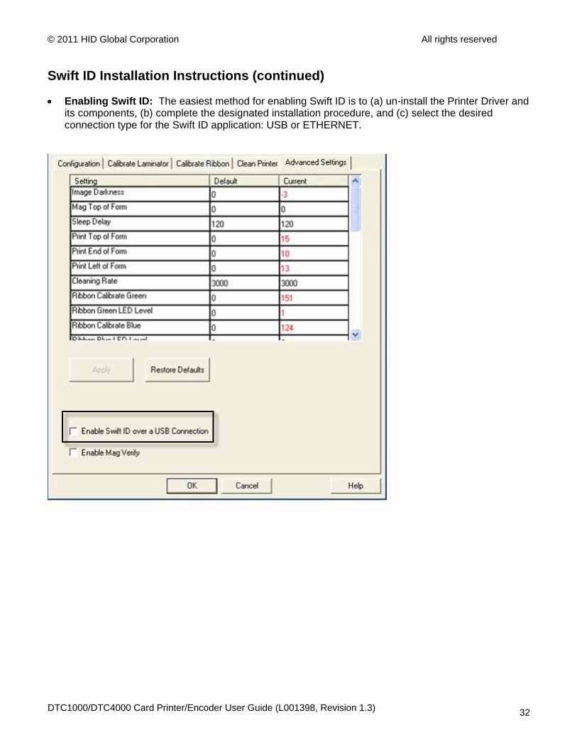
• Enabling Swift ID: The easiest method for enabling Swift ID is to (a) un-install the Printer Driver and its components, (b) complete the designated installation procedure, and (c) select the desired connection type for the Swift ID application: USB or ETHERNET.
DTC1000/DTC4000 Card Printer/Encoder User Guide (L001398, Revision 1.3) 32
© 2011 HID Global Corporation All rights reserved
Installing Swift ID
DTC1000/DTC4000 Card Printer/Encoder User Guide (L001398, Revision 1.3) 33
© 2011 HID Global Corporation All rights reserved
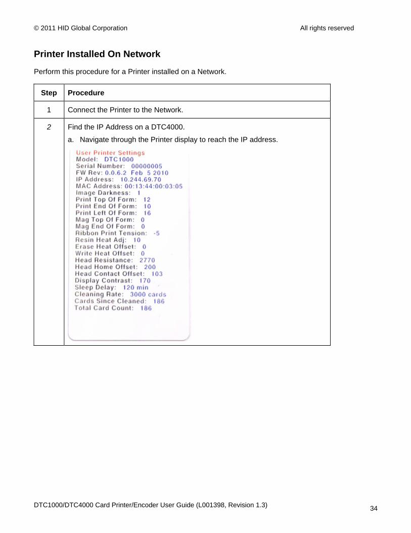
Printer Installed On Network
Perform this procedure for a Printer installed on a Network.
Step Procedure
1 Connect the Printer to the Network.
2 Find the IP Address on a DTC4000.
a. Navigate through the Printer display to reach the IP address.
DTC1000/DTC4000 Card Printer/Encoder User Guide (L001398, Revision 1.3) 34
© 2011 HID Global Corporation All rights reserved
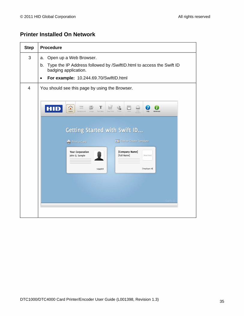
Printer Installed On Network
Step Procedure
3 a. Open up a Web Browser.
b. Type the IP Address followed by /SwiftID.html to access the Swift ID badging application.
• For example: 10.244.69.70/SwiftID.html
4 You should see this page by using the Browser.
DTC1000/DTC4000 Card Printer/Encoder User Guide (L001398, Revision 1.3) 35
© 2011 HID Global Corporation All rights reserved
Printer Connected Via USB Connection Perform this procedure when attempting to use Swift ID on the initial setup of a Printer connected via a USB connection. (Note: This application is not intended for use with multiple printers.)
• To start using Swift ID via a USB connection with a DTC1000, DTC4000, or a DTC4500 that has already been installed on the PC, please choose Option No. 1 or No. 2 and complete the procedure.
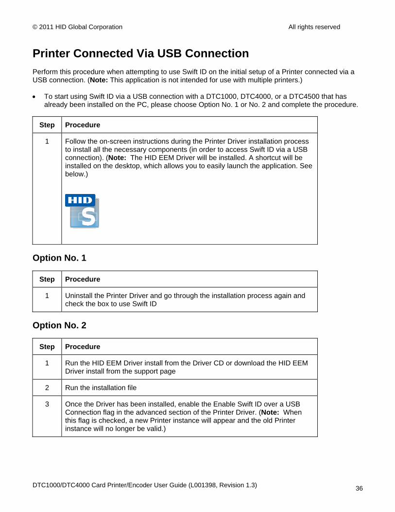
Step Procedure
1 Follow the on-screen instructions during the Printer Driver installation process to install all the necessary components (in order to access Swift ID via a USB connection). (Note: The HID EEM Driver will be installed. A shortcut will be installed on the desktop, which allows you to easily launch the application. See below.)
Option No. 1
Step Procedure
1 Uninstall the Printer Driver and go through the installation process again and check the box to use Swift ID
Option No. 2
Step Procedure
1 Run the HID EEM Driver install from the Driver CD or download the HID EEM Driver install from the support page
2 Run the installation file
3 Once the Driver has been installed, enable the Enable Swift ID over a USB Connection flag in the advanced section of the Printer Driver. (Note: When this flag is checked, a new Printer instance will appear and the old Printer instance will no longer be valid.)
DTC1000/DTC4000 Card Printer/Encoder User Guide (L001398, Revision 1.3) 36
© 2011 HID Global Corporation All rights reserved
Uninstalling Swift ID
Please follow these instructions:
• For a printer installed on a Network: There are no steps needed to remove any of the components of Swift ID.
• For a printer that is connected via a USB connection: Disable the Enable Swift ID over a USB Connection flag in the advanced section of the Printer Driver and then ‘run’ the uninstall HID EEM Driver setup. (Note: When this flag is disabled, a new Printer instance will appear and the old Printer instance will no longer be valid.)
Additional Swift ID Rules
The following happens when (a) the HID EEM Driver for Swift ID has been installed on the PC for a Printer and (b) a second Printer with the EEM flag turned on is connected to the PC:
• A Printer instance will appear for the second Printer; however, a second shortcut for Swift ID will not appear. (Note: Swift ID is not intended to operate with two Printers.)
• If both Printers are connected to the PC, the Printer (that is first turned on) will be tied into Swift ID
The following happens when (a) the EEM Driver has not been installed on the PC and (b) another Printer (same model) with the EEM flag turned off is connected to the PC.
• A Printer Driver instance will appear.
• The User will not be asked to turn on the flag in the Printer.
• The HID EEM Driver will not be installed in the on the PC.
• The EEM flag in the Printer Driver will be ‘greyed out’; so that the User cannot alter this state.
DTC1000/DTC4000 Card Printer/Encoder User Guide (L001398, Revision 1.3) 37
© 2011 HID Global Corporation All rights reserved
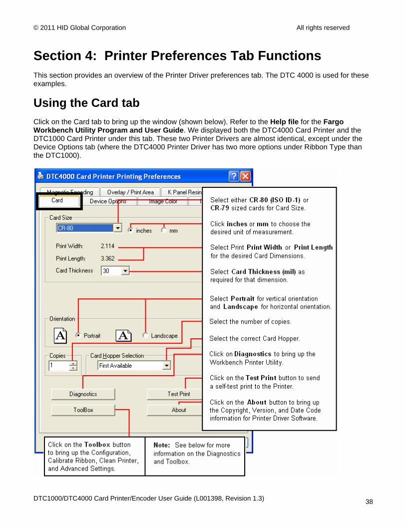
Section 4: Printer Preferences Tab Functions This section provides an overview of the Printer Driver preferences tab. The DTC 4000 is used for these examples.
Using the Card tab Click on the Card tab to bring up the window (shown below). Refer to the Help file for the Fargo Workbench Utility Program and User Guide. We displayed both the DTC4000 Card Printer and the DTC1000 Card Printer under this tab. These two Printer Drivers are almost identical, except under the Device Options tab (where the DTC4000 Printer Driver has two more options under Ribbon Type than the DTC1000).
DTC1000/DTC4000 Card Printer/Encoder User Guide (L001398, Revision 1.3) 38
© 2011 HID Global Corporation All rights reserved
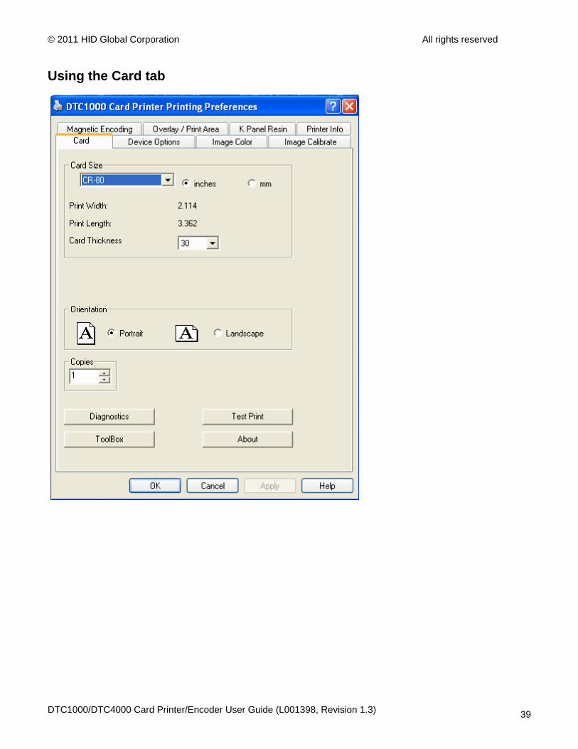
Using the Card tab
DTC1000/DTC4000 Card Printer/Encoder User Guide (L001398, Revision 1.3) 39
© 2011 HID Global Corporation All rights reserved
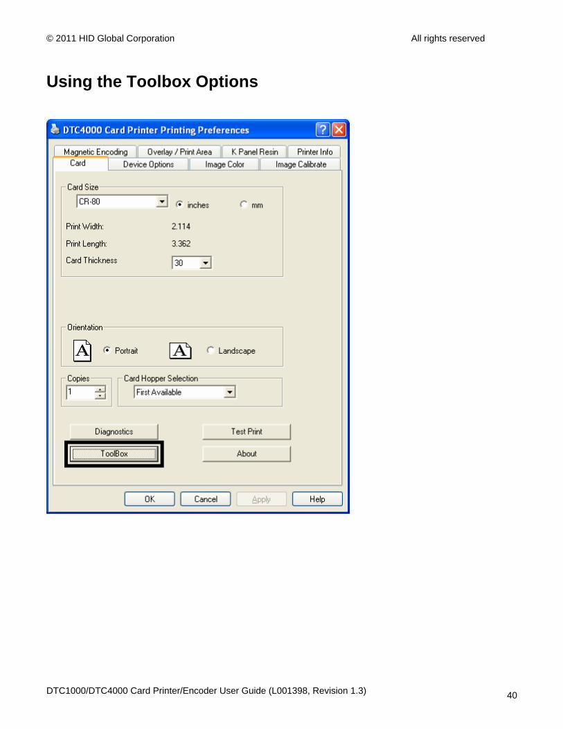
Using the Toolbox Options
DTC1000/DTC4000 Card Printer/Encoder User Guide (L001398, Revision 1.3) 40
© 2011 HID Global Corporation All rights reserved
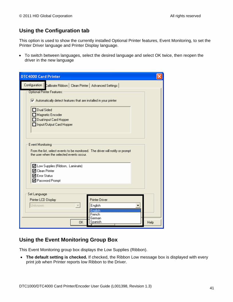
Using the Configuration tab
This option is used to show the currently installed Optional Printer features, Event Monitoring, to set the Printer Driver language and Printer Display language. • To switch between languages, select the desired language and select OK twice, then reopen the
driver in the new language
Using the Event Monitoring Group Box
This Event Monitoring group box displays the Low Supplies (Ribbon).
• The default setting is checked. If checked, the Ribbon Low message box is displayed with every print job when Printer reports low Ribbon to the Driver.
DTC1000/DTC4000 Card Printer/Encoder User Guide (L001398, Revision 1.3) 41
© 2011 HID Global Corporation All rights reserved
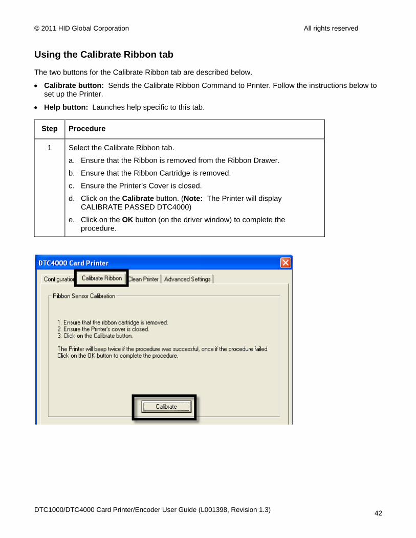
Using the Calibrate Ribbon tab
The two buttons for the Calibrate Ribbon tab are described below.
• Calibrate button: Sends the Calibrate Ribbon Command to Printer. Follow the instructions below to set up the Printer.
• Help button: Launches help specific to this tab.
Step Procedure
1 Select the Calibrate Ribbon tab.
a. Ensure that the Ribbon is removed from the Ribbon Drawer.
b. Ensure that the Ribbon Cartridge is removed.
c. Ensure the Printer’s Cover is closed.
d. Click on the Calibrate button. (Note: The Printer will display CALIBRATE PASSED DTC4000)
e. Click on the OK button (on the driver window) to complete the procedure.
DTC1000/DTC4000 Card Printer/Encoder User Guide (L001398, Revision 1.3) 42
© 2011 HID Global Corporation All rights reserved
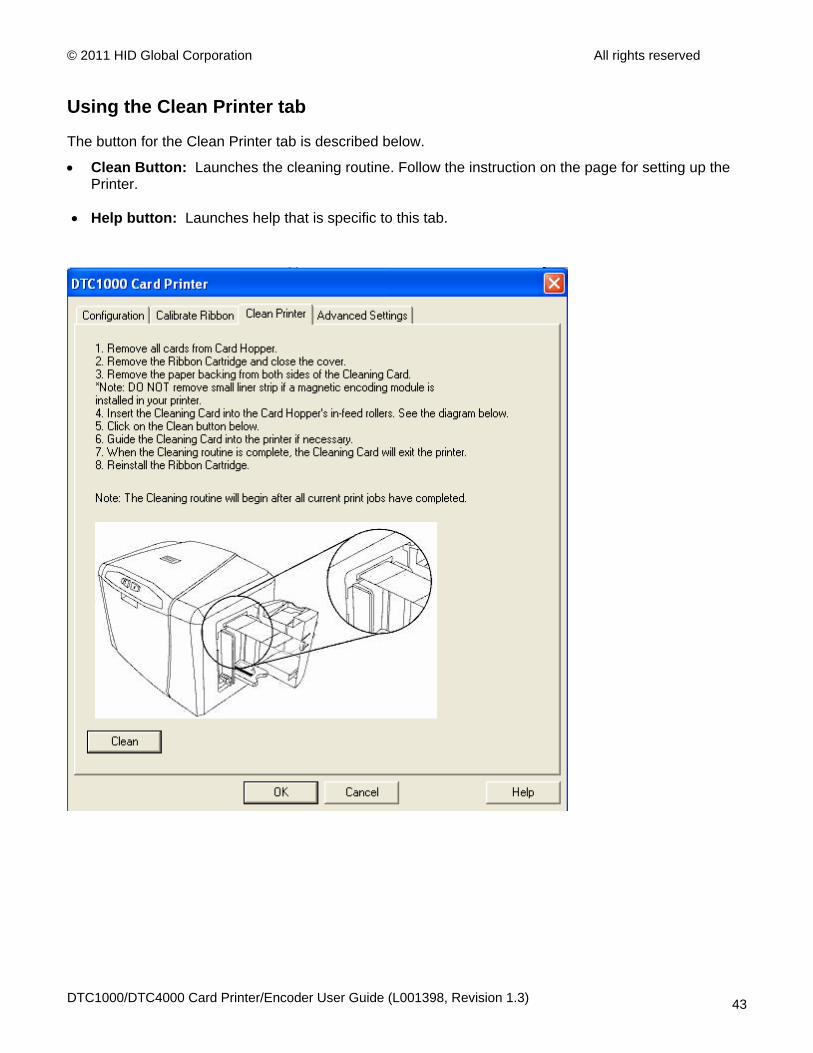
Using the Clean Printer tab
The button for the Clean Printer tab is described below.
• Clean Button: Launches the cleaning routine. Follow the instruction on the page for setting up the Printer.
• Help button: Launches help that is specific to this tab.
DTC1000/DTC4000 Card Printer/Encoder User Guide (L001398, Revision 1.3) 43
© 2011 HID Global Corporation All rights reserved
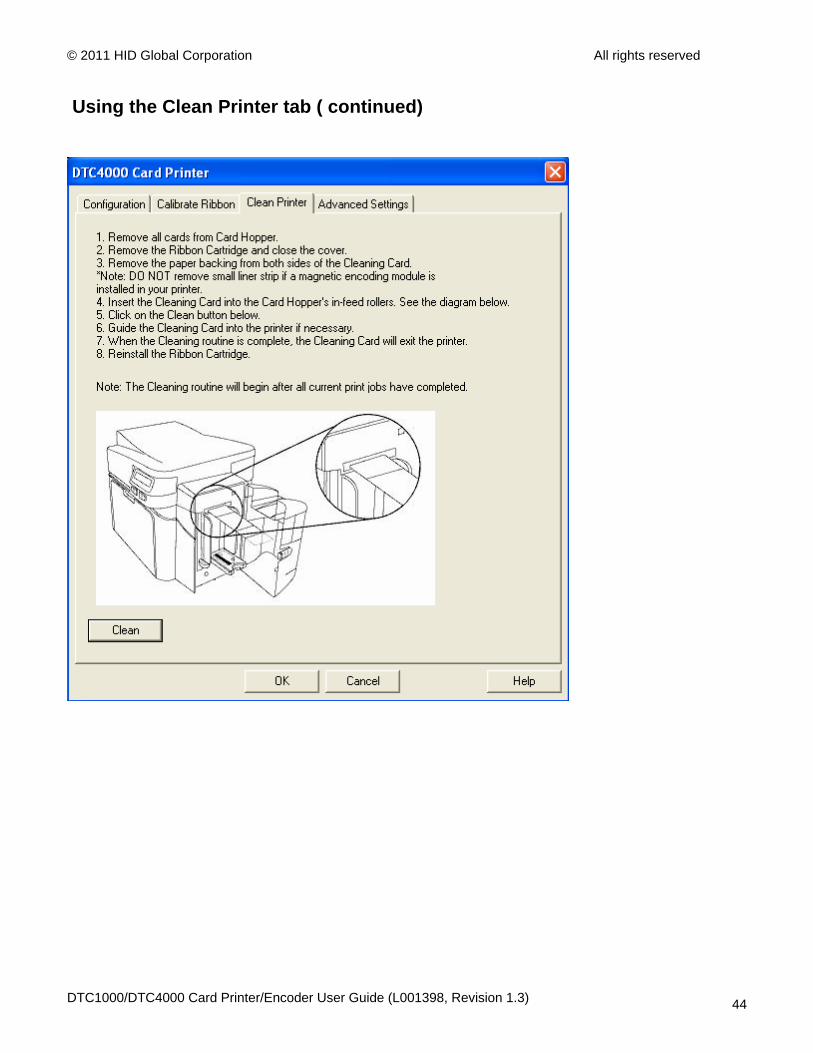
Using the Clean Printer tab ( continued)
DTC1000/DTC4000 Card Printer/Encoder User Guide (L001398, Revision 1.3) 44

© 2011 HID Global Corporation All rights reserved
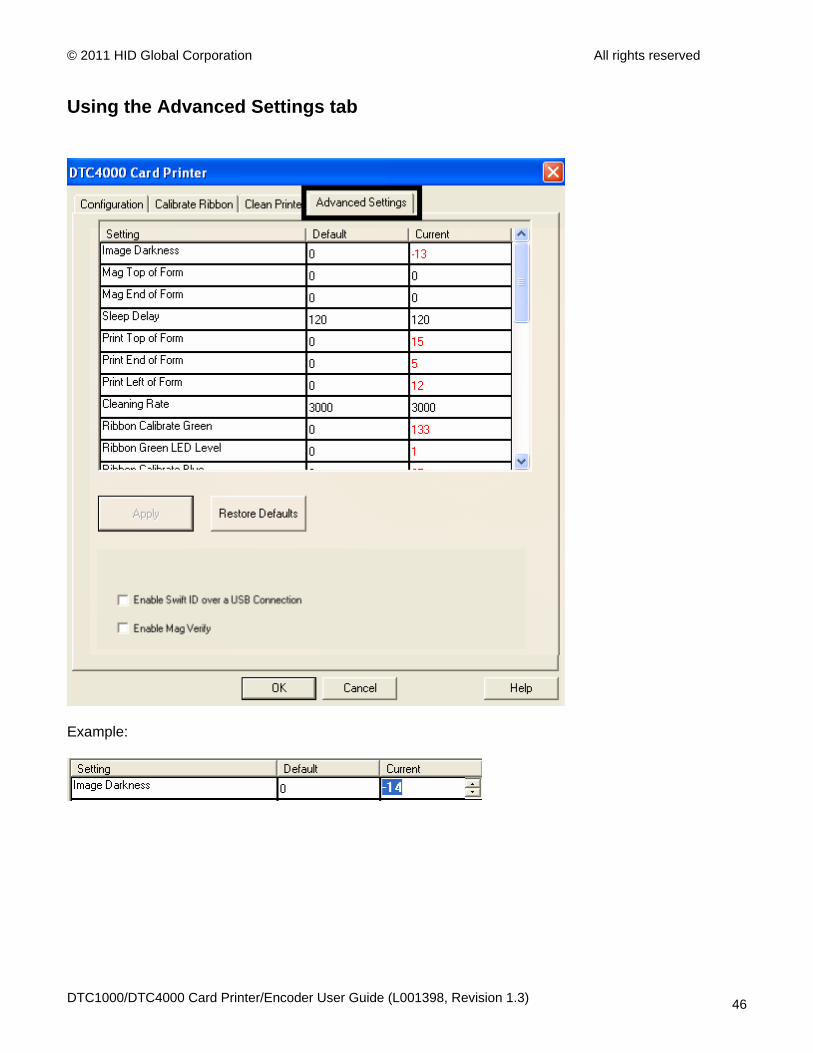
Using the Advanced Settings tab
Use the Advanced Settings tab for adjusting the internal Printer settings, which are customized for every Printer at the factory and saved directly within the Printer's memory. (Note: You can select the Restore Defaults to restore the internal default settings.)
These change values for Firmware settings. See below.
• Setting Column: Displays label for setting
• Default Column: Displays default value for setting
• Current Column: Displays current value for setting
• Change the value by clicking on the value to activate spin control or type.
• Apply Button: Applies changed values.
• Restore Defaults Button: Restores default values.
• Enable Swift ID if using a USB connection.
DTC1000/DTC4000 Card Printer/Encoder User Guide (L001398, Revision 1.3) 45
© 2011 HID Global Corporation All rights reserved
Using the Advanced Settings tab
Example:
DTC1000/DTC4000 Card Printer/Encoder User Guide (L001398, Revision 1.3) 46
© 2011 HID Global Corporation All rights reserved
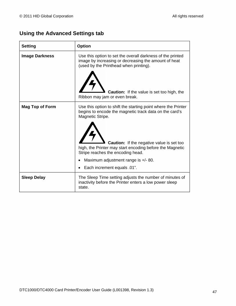
Using the Advanced Settings tab
Setting Option
Image Darkness Use this option to set the overall darkness of the printed image by increasing or decreasing the amount of heat (used by the Printhead when printing).
Caution: If the value is set too high, the Ribbon may jam or even break.
Mag Top of Form Use this option to shift the starting point where the Printer begins to encode the magnetic track data on the card’s Magnetic Stripe.
Caution: If the negative value is set too high, the Printer may start encoding before the Magnetic Stripe reaches the encoding head.
• Maximum adjustment range is +/- 80.
• Each increment equals .01”.
Sleep Delay The Sleep Time setting adjusts the number of minutes of inactivity before the Printer enters a low power sleep state.
DTC1000/DTC4000 Card Printer/Encoder User Guide (L001398, Revision 1.3) 47
© 2011 HID Global Corporation All rights reserved
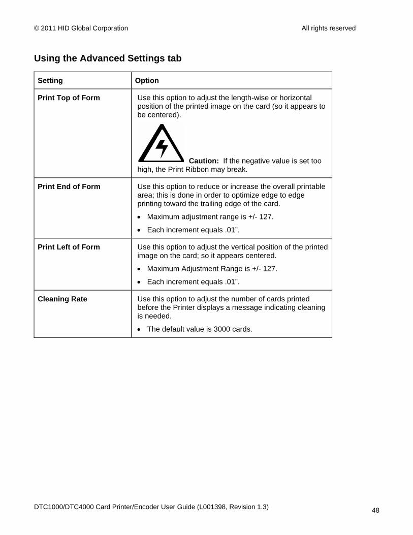
Using the Advanced Settings tab
Setting Option
Print Top of Form Use this option to adjust the length-wise or horizontal position of the printed image on the card (so it appears to be centered).
Caution: If the negative value is set too high, the Print Ribbon may break.
Print End of Form Use this option to reduce or increase the overall printable area; this is done in order to optimize edge to edge printing toward the trailing edge of the card.
• Maximum adjustment range is +/- 127.
• Each increment equals .01”.
Print Left of Form Use this option to adjust the vertical position of the printed image on the card; so it appears centered.
• Maximum Adjustment Range is +/- 127.
• Each increment equals .01”.
Cleaning Rate Use this option to adjust the number of cards printed before the Printer displays a message indicating cleaning is needed.
• The default value is 3000 cards.
DTC1000/DTC4000 Card Printer/Encoder User Guide (L001398, Revision 1.3) 48
© 2011 HID Global Corporation All rights reserved
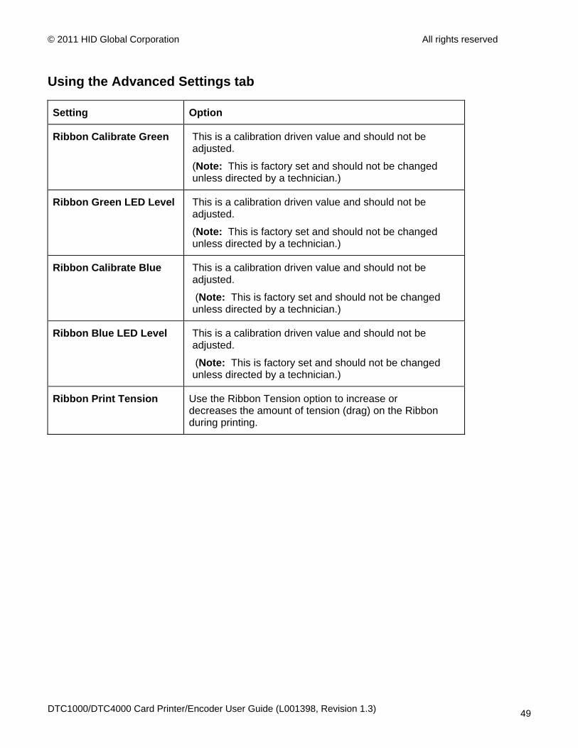
Using the Advanced Settings tab
Setting Option
Ribbon Calibrate Green This is a calibration driven value and should not be adjusted.
(Note: This is factory set and should not be changed unless directed by a technician.)
Ribbon Green LED Level This is a calibration driven value and should not be adjusted.
(Note: This is factory set and should not be changed unless directed by a technician.)
Ribbon Calibrate Blue This is a calibration driven value and should not be adjusted.
(Note: This is factory set and should not be changed unless directed by a technician.)
Ribbon Blue LED Level This is a calibration driven value and should not be adjusted.
(Note: This is factory set and should not be changed unless directed by a technician.)
Ribbon Print Tension Use the Ribbon Tension option to increase or decreases the amount of tension (drag) on the Ribbon during printing.
DTC1000/DTC4000 Card Printer/Encoder User Guide (L001398, Revision 1.3) 49
© 2011 HID Global Corporation All rights reserved
Using the Advanced Settings tab
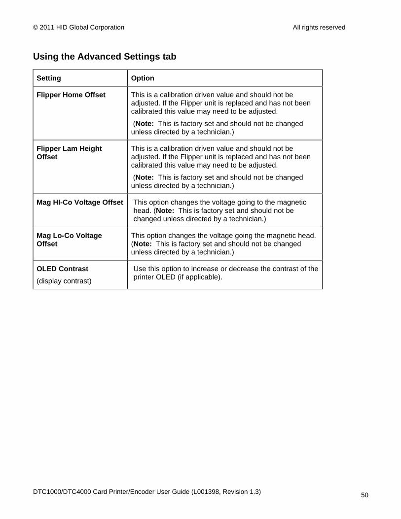
Setting Option
Flipper Home Offset This is a calibration driven value and should not be adjusted. If the Flipper unit is replaced and has not been calibrated this value may need to be adjusted.
(Note: This is factory set and should not be changed unless directed by a technician.)
Flipper Lam Height Offset
This is a calibration driven value and should not be adjusted. If the Flipper unit is replaced and has not been calibrated this value may need to be adjusted.
(Note: This is factory set and should not be changed unless directed by a technician.)
Mag HI-Co Voltage Offset This option changes the voltage going to the magnetic head. (Note: This is factory set and should not be changed unless directed by a technician.)
Mag Lo-Co Voltage Offset
This option changes the voltage going the magnetic head. (Note: This is factory set and should not be changed unless directed by a technician.)
OLED Contrast (display contrast)
Use this option to increase or decrease the contrast of the printer OLED (if applicable).
DTC1000/DTC4000 Card Printer/Encoder User Guide (L001398, Revision 1.3) 50

© 2011 HID Global Corporation All rights reserved
Using the Advanced Settings tab
Setting Option
Resin Heat Adjust Use this adjustment for Black resin text and barcodes if they appear faded or too light/dark.
• Maximum Adjustment Range is +/- 100.
(Note: This control can be helpful for fine-tuning the transfer of resin text and bar codes.)
Head Resistance This is factory set. If the main board or the Printhead is replaced then adjust this number.
Locate the Printhead Setting Number on the bottom of the Printhead.
The number reads R=XXXX.
Head Home Offset This is a calibration driven value and should not be adjusted. If the Printhead assembly is replaced then this value may need to be adjusted.
(Note: This is factory set and should not be changed unless directed by a technician.)
Head Contact Offset This is a calibration driven value and should not be adjusted. If the Printhead assembly is replaced then this value may need to be adjusted.
(Note: This is factory set and should not be changed unless directed by a technician.)
DTC1000/DTC4000 Card Printer/Encoder User Guide (L001398, Revision 1.3) 51
© 2011 HID Global Corporation All rights reserved
Using the Advanced Settings tab
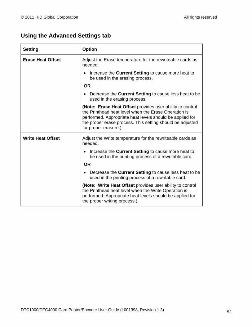
Setting Option
Erase Heat Offset Adjust the Erase temperature for the rewriteable cards as needed.
• Increase the Current Setting to cause more heat to be used in the erasing process.
OR
• Decrease the Current Setting to cause less heat to be used in the erasing process.
(Note: Erase Heat Offset provides user ability to control the Printhead heat level when the Erase Operation is performed. Appropriate heat levels should be applied for the proper erase process. This setting should be adjusted for proper erasure.)
Write Heat Offset Adjust the Write temperature for the rewriteable cards as needed.
• Increase the Current Setting to cause more heat to be used in the printing process of a rewritable card.
OR
• Decrease the Current Setting to cause less heat to be used in the printing process of a rewritable card.
(Note: Write Heat Offset provides user ability to control the Printhead heat level when the Write Operation is performed. Appropriate heat levels should be applied for the proper writing process.)
DTC1000/DTC4000 Card Printer/Encoder User Guide (L001398, Revision 1.3) 52
© 2011 HID Global Corporation All rights reserved
Using the Advanced Settings tab
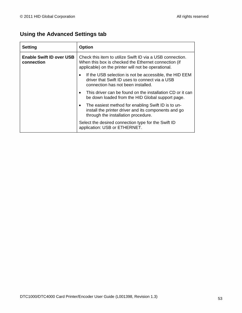
Setting Option
Enable Swift ID over USB connection
Check this item to utilize Swift ID via a USB connection. When this box is checked the Ethernet connection (if applicable) on the printer will not be operational.
• If the USB selection is not be accessible, the HID EEM driver that Swift ID uses to connect via a USB connection has not been installed.
• This driver can be found on the installation CD or it can be down loaded from the HID Global support page.
• The easiest method for enabling Swift ID is to un-install the printer driver and its components and go through the installation procedure.
Select the desired connection type for the Swift ID application: USB or ETHERNET.
DTC1000/DTC4000 Card Printer/Encoder User Guide (L001398, Revision 1.3) 53
© 2011 HID Global Corporation All rights reserved
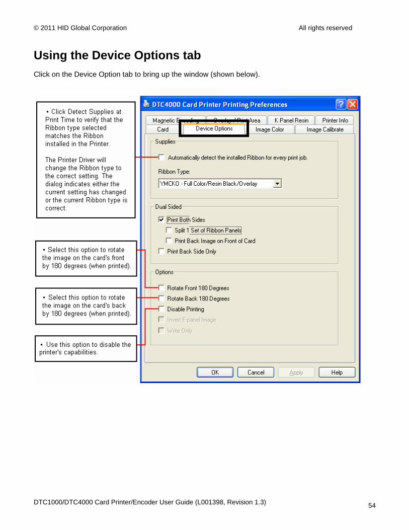
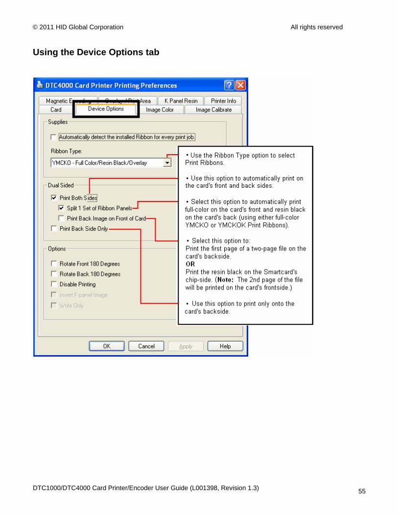
Using the Device Options tab Click on the Device Option tab to bring up the window (shown below).
DTC1000/DTC4000 Card Printer/Encoder User Guide (L001398, Revision 1.3) 54
© 2011 HID Global Corporation All rights reserved
Using the Device Options tab
DTC1000/DTC4000 Card Printer/Encoder User Guide (L001398, Revision 1.3) 55
© 2011 HID Global Corporation All rights reserved
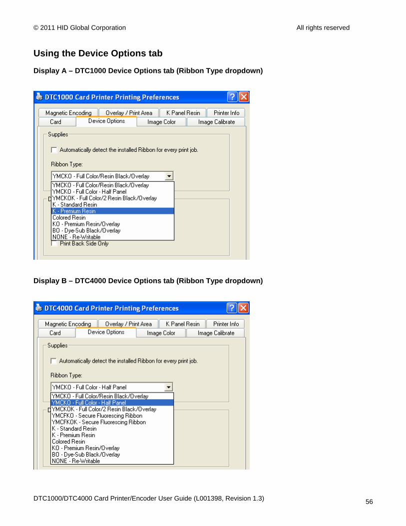
Using the Device Options tab
Display A – DTC1000 Device Options tab (Ribbon Type dropdown)
Display B – DTC4000 Device Options tab (Ribbon Type dropdown)
DTC1000/DTC4000 Card Printer/Encoder User Guide (L001398, Revision 1.3) 56

© 2011 HID Global Corporation All rights reserved
Using the Device Options tab
DTC1000/DTC4000 Card Printer/Encoder User Guide (L001398, Revision 1.3) 57

© 2011 HID Global Corporation All rights reserved
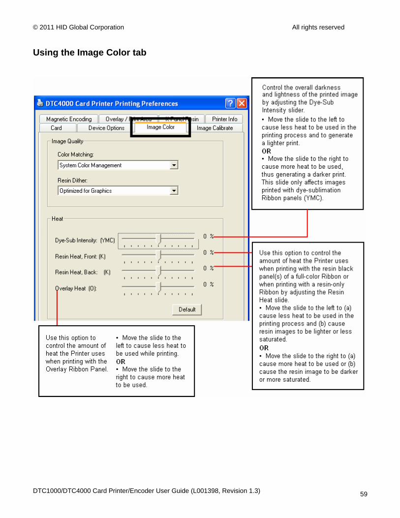
Using the Image Color tab Click on the Image Color option tab to bring up the window (shown below).
DTC1000/DTC4000 Card Printer/Encoder User Guide (L001398, Revision 1.3) 58
© 2011 HID Global Corporation All rights reserved
Using the Image Color tab
DTC1000/DTC4000 Card Printer/Encoder User Guide (L001398, Revision 1.3) 59
© 2011 HID Global Corporation All rights reserved
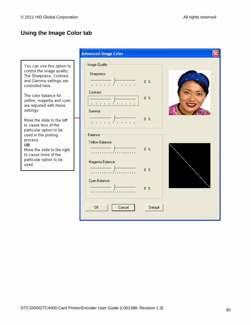
Using the Image Color tab
DTC1000/DTC4000 Card Printer/Encoder User Guide (L001398, Revision 1.3) 60
© 2011 HID Global Corporation All rights reserved
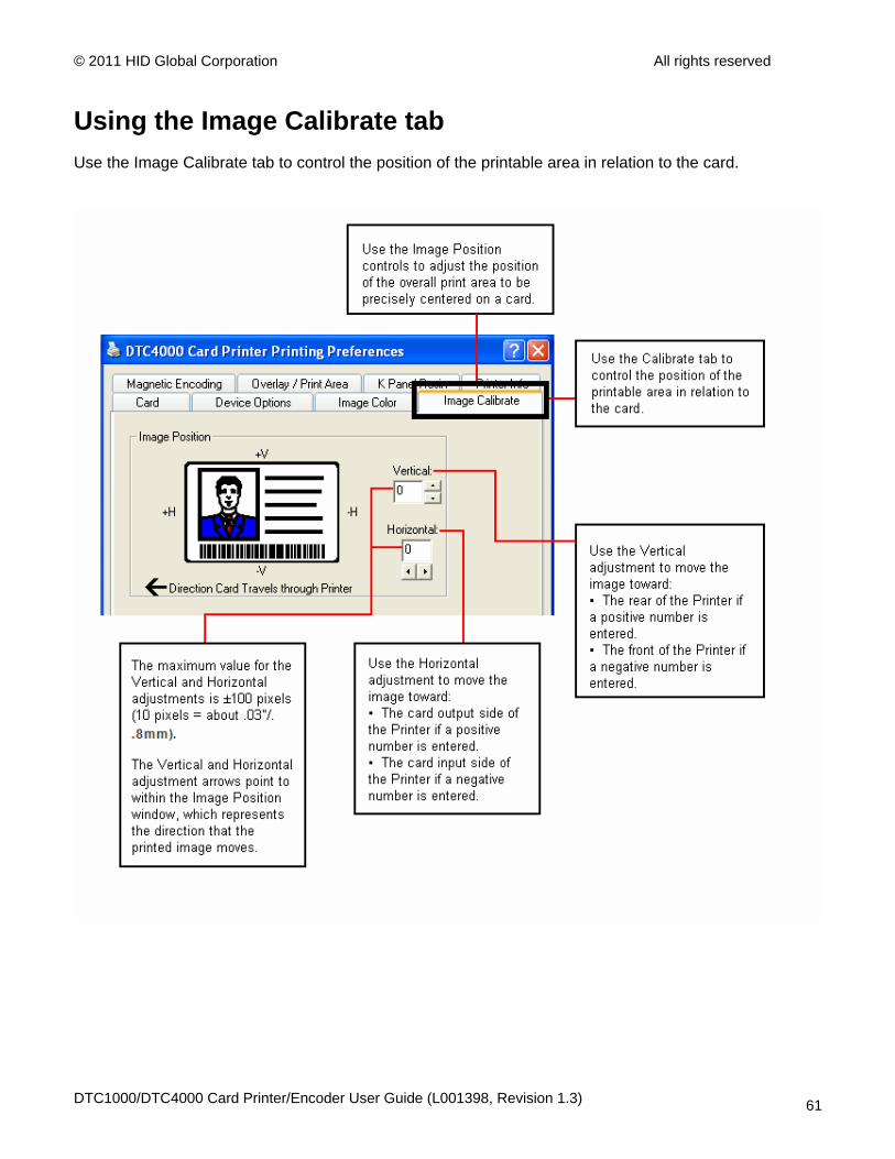
Using the Image Calibrate tab Use the Image Calibrate tab to control the position of the printable area in relation to the card.
DTC1000/DTC4000 Card Printer/Encoder User Guide (L001398, Revision 1.3) 61

© 2011 HID Global Corporation All rights reserved
Using the Magnetic Encoding Tab
Select the Magnetic Encoding tab to display options for controlling the Magnetic Stripe encoding process. You should use these options only if the Printer has an optional Magnetic Stripe Encoding Module installed.
DTC1000/DTC4000 Card Printer/Encoder User Guide (L001398, Revision 1.3) 62
© 2011 HID Global Corporation All rights reserved
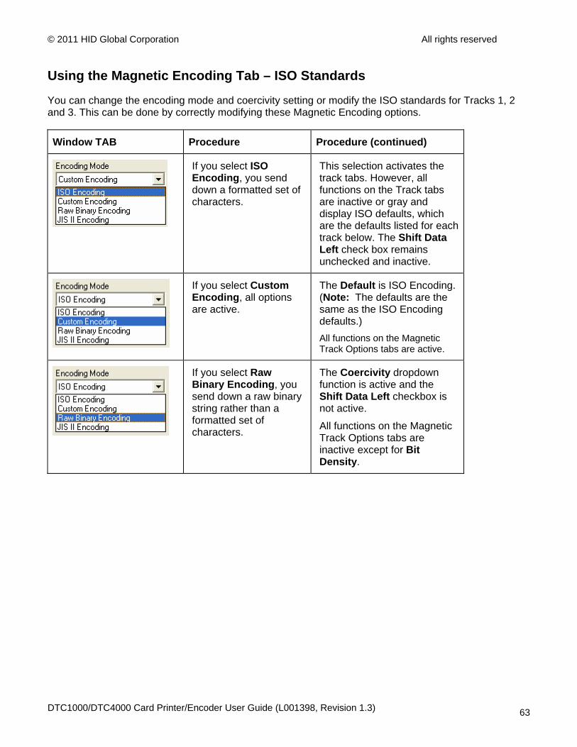
Using the Magnetic Encoding Tab – ISO Standards
You can change the encoding mode and coercivity setting or modify the ISO standards for Tracks 1, 2 and 3. This can be done by correctly modifying these Magnetic Encoding options.
Window TAB Procedure Procedure (continued)
If you select ISO Encoding, you send down a formatted set of characters.
This selection activates the track tabs. However, all functions on the Track tabs are inactive or gray and display ISO defaults, which are the defaults listed for each track below. The Shift Data Left check box remains unchecked and inactive.
If you select Custom Encoding, all options are active.
The Default is ISO Encoding. (Note: The defaults are the same as the ISO Encoding defaults.) All functions on the Magnetic Track Options tabs are active.
If you select Raw Binary Encoding, you send down a raw binary string rather than a formatted set of characters.
The Coercivity dropdown function is active and the Shift Data Left checkbox is not active.
All functions on the Magnetic Track Options tabs are inactive except for Bit Density.
DTC1000/DTC4000 Card Printer/Encoder User Guide (L001398, Revision 1.3) 63
© 2011 HID Global Corporation All rights reserved
Using the Magnetic Encoding Tab – ISO Standards
Window TAB Procedure Procedure (continued)
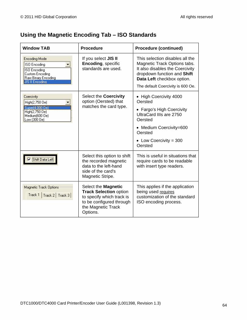
If you select JIS II Encoding, specific standards are used.
This selection disables all the Magnetic Track Options tabs. It also disables the Coercivity dropdown function and Shift Data Left checkbox option. The default Coercivity is 600 Oe.
Select the Coercivity option (Oersted) that matches the card type.
• High Coercivity 4000 Oersted
• Fargo’s High Coercivity UltraCard IIIs are 2750 Oersted
• Medium Coercivity=600 Oersted
• Low Coercivity = 300 Oersted
Select this option to shift the recorded magnetic data to the left-hand side of the card's Magnetic Stripe.
This is useful in situations that require cards to be readable with insert type readers.
Select the Magnetic Track Selection option to specify which track is to be configured through the Magnetic Track Options.
This applies if the application being used requires customization of the standard ISO encoding process.
DTC1000/DTC4000 Card Printer/Encoder User Guide (L001398, Revision 1.3) 64
© 2011 HID Global Corporation All rights reserved
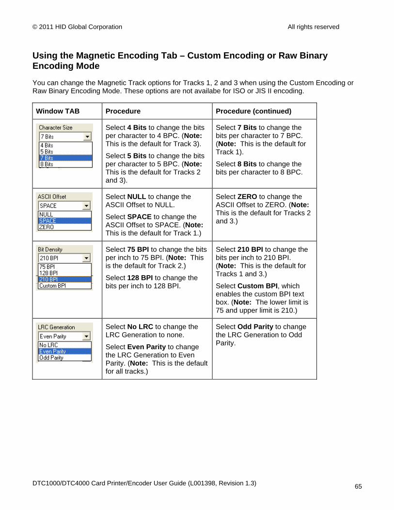
Using the Magnetic Encoding Tab – Custom Encoding or Raw Binary Encoding Mode
You can change the Magnetic Track options for Tracks 1, 2 and 3 when using the Custom Encoding or Raw Binary Encoding Mode. These options are not availabe for ISO or JIS II encoding.
Window TAB Procedure Procedure (continued)
Select 4 Bits to change the bits per character to 4 BPC. (Note: This is the default for Track 3).
Select 5 Bits to change the bits per character to 5 BPC. (Note: This is the default for Tracks 2 and 3).
Select 7 Bits to change the bits per character to 7 BPC. (Note: This is the default for Track 1).
Select 8 Bits to change the bits per character to 8 BPC.
Select NULL to change the ASCII Offset to NULL.
Select SPACE to change the ASCII Offset to SPACE. (Note: This is the default for Track 1.)
Select ZERO to change the ASCII Offset to ZERO. (Note: This is the default for Tracks 2 and 3.)
Select 75 BPI to change the bits per inch to 75 BPI. (Note: This is the default for Track 2.)
Select 128 BPI to change the bits per inch to 128 BPI.
Select 210 BPI to change the bits per inch to 210 BPI. (Note: This is the default for Tracks 1 and 3.)
Select Custom BPI, which enables the custom BPI text box. (Note: The lower limit is 75 and upper limit is 210.)
Select No LRC to change the LRC Generation to none.
Select Even Parity to change the LRC Generation to Even Parity. (Note: This is the default for all tracks.)
Select Odd Parity to change the LRC Generation to Odd Parity.
DTC1000/DTC4000 Card Printer/Encoder User Guide (L001398, Revision 1.3) 65
© 2011 HID Global Corporation All rights reserved
Using the Magnetic Encoding Tab – Custom Encoding or Raw Binary Encoding Mode
Window TAB Procedure Procedure (continued)
Select No Parity to change the Character Parity to none.
Select Even Parity to change the Character Parity to Even Parity.
Select Odd Parity to change the Character Parity to Odd Parity. (Note: This is the default for all tracks.)
Reverse Bit Order is used to reverse the character bits and is used for the encryption of data in specific programs
Add Leading Zeros is used to add a set number of leading zeros to the magnetic string in order to move the starting point of the encoded data in specific programs for encryption of data.
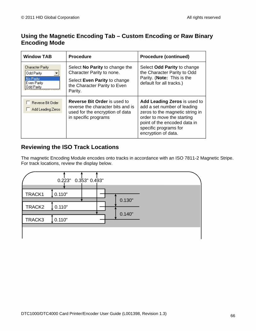
Reviewing the ISO Track Locations
The magnetic Encoding Module encodes onto tracks in accordance with an ISO 7811-2 Magnetic Stripe. For track locations, review the display below.
TRACK1 0.110"
TRACK2 0.110"
TRACK3 0.110"
0.130"
0.140"
0.223" 0.353" 0.493"
DTC1000/DTC4000 Card Printer/Encoder User Guide (L001398, Revision 1.3) 66
© 2011 HID Global Corporation All rights reserved
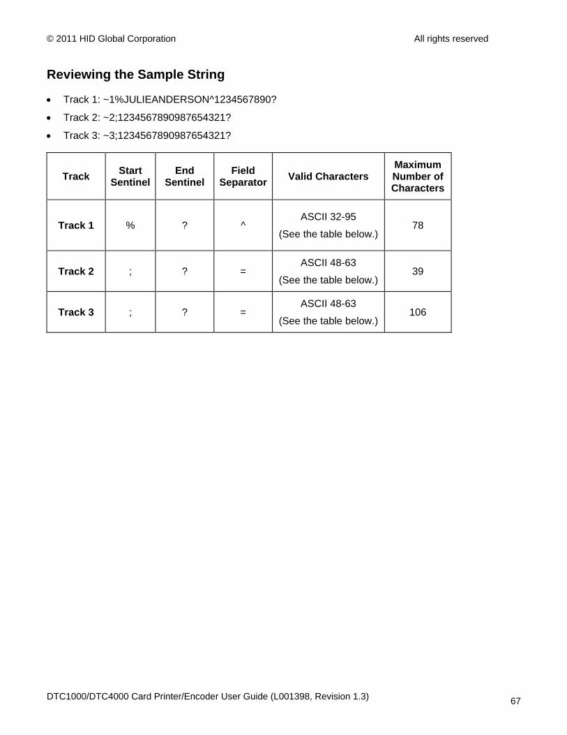
Reviewing the Sample String
• Track 1: ~1%JULIEANDERSON^1234567890?
• Track 2: ~2;1234567890987654321?
• Track 3: ~3;1234567890987654321?
Track Start Sentinel
End Sentinel
Field Separator Valid Characters
Maximum Number of Characters
Track 1 % ? ^ ASCII 32-95
(See the table below.) 78
Track 2 ; ? = ASCII 48-63
(See the table below.) 39
Track 3 ; ? = ASCII 48-63
(See the table below.) 106
DTC1000/DTC4000 Card Printer/Encoder User Guide (L001398, Revision 1.3) 67

© 2011 HID Global Corporation All rights reserved
Sending the Track Information
Magnetic track data is sent in the form of text strings from the application software to the Printer Driver.
• In order for the Printer Driver to differentiate between Magnetic Track data and the rest of the printable objects, specific characters must be added to the magnetic data to be encoded.
• These specify the data that is to be encoded, the tracks to encode and mark the start and stop of the data string. In some cases, these specific characters are automatically added to the string of track data by ID software applications.
• In most cases, the user must carefully add these characters to the string of Magnetic Track data. If these characters are not added to the track data, the text intended for the Magnetic Track will appear as printed text on the card. To avoid this, track information must be entered as described below.
Step Procedure
1 When entering track data, the ~ (tilde) character is entered first, followed by the track number (1, 2 or 3) on which the data should encode. This is followed by the data to be encoded.
• The first character of this data string must be the track's specific Start Sentinel (SS) and the last character must be the specific End Sentinel (ES).
• The characters or data in between the SS and ES can include all of the valid characters specific to each track.
• The number of these characters, however, is limited by each track's maximum character capacity.
• When segmenting track data, the appropriate Field Separator (FS) must be used. The table below shows the SS, ES, FS and the valid characters defined for each track.
DTC1000/DTC4000 Card Printer/Encoder User Guide (L001398, Revision 1.3) 68
© 2011 HID Global Corporation All rights reserved
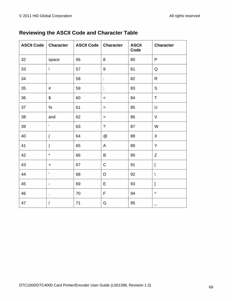
Reviewing the ASCII Code and Character Table
ASCII Code Character ASCII Code Character ASCII Code
Character
32 space 56 8 80 P
33 ! 57 9 81 Q
34 58 : 82 R
35 # 59 ; 83 S
36 $ 60 < 84 T
37 % 61 = 85 U
38 and 62 > 86 V
39 ' 63 ? 87 W
40 ( 64 @ 88 X
41 ) 65 A 89 Y
42 * 66 B 90 Z
43 + 67 C 91 [
44 ' 68 D 92 \
45 - 69 E 93 ]
46 . 70 F 94 ^
47 / 71 G 95 _
DTC1000/DTC4000 Card Printer/Encoder User Guide (L001398, Revision 1.3) 69
© 2011 HID Global Corporation All rights reserved
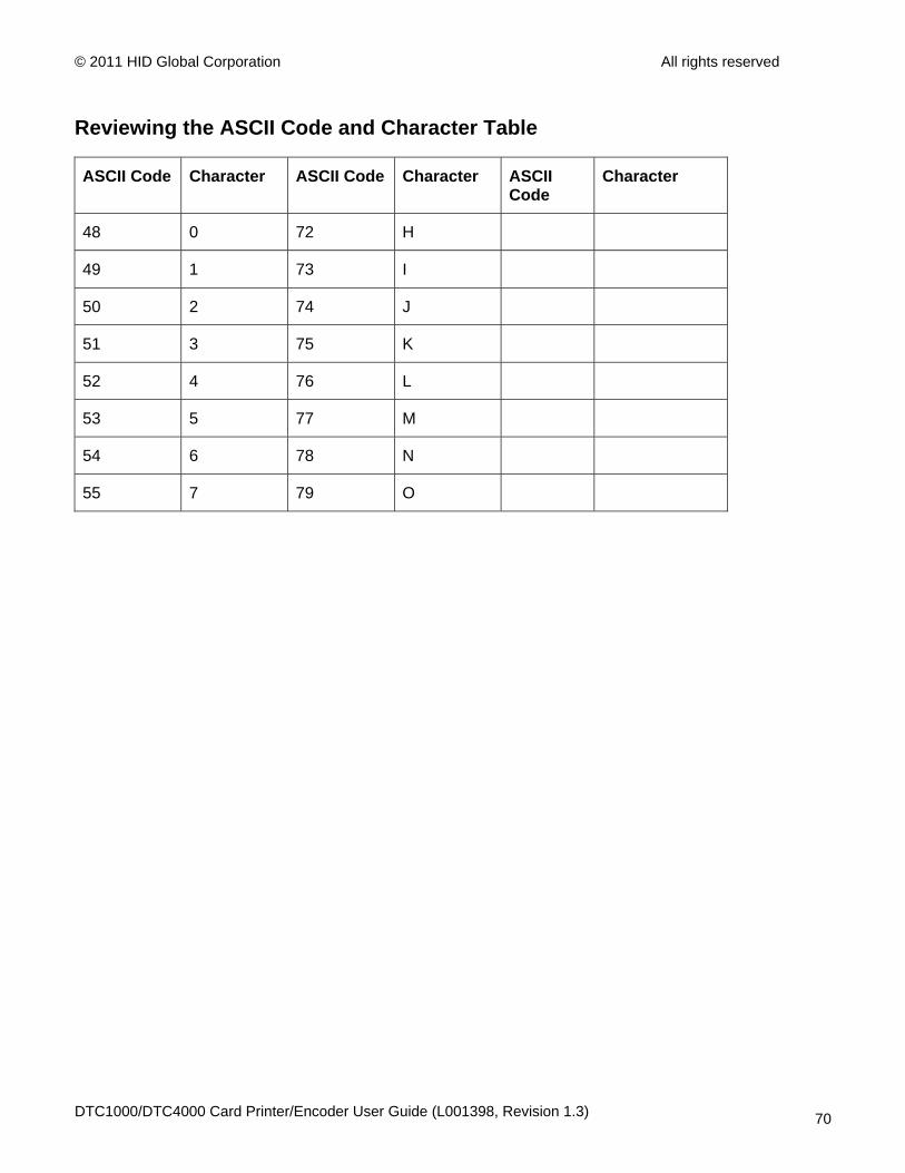
Reviewing the ASCII Code and Character Table
ASCII Code Character ASCII Code Character ASCII Code
Character
48 0 72 H
49 1 73 I
50 2 74 J
51 3 75 K
52 4 76 L
53 5 77 M
54 6 78 N
55 7 79 O
DTC1000/DTC4000 Card Printer/Encoder User Guide (L001398, Revision 1.3) 70
© 2011 HID Global Corporation All rights reserved
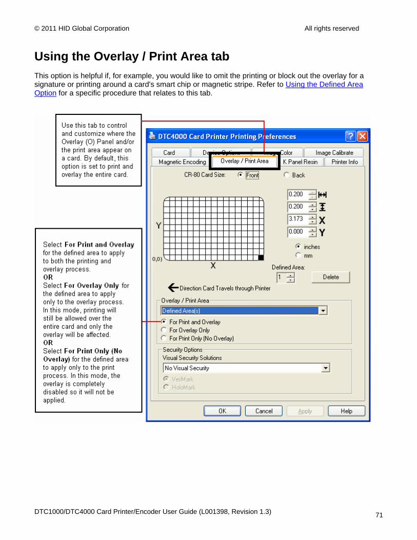
Using the Overlay / Print Area tab This option is helpful if, for example, you would like to omit the printing or block out the overlay for a signature or printing around a card's smart chip or magnetic stripe. Refer to Using the Defined Area Option for a specific procedure that relates to this tab.
DTC1000/DTC4000 Card Printer/Encoder User Guide (L001398, Revision 1.3) 71
© 2011 HID Global Corporation All rights reserved
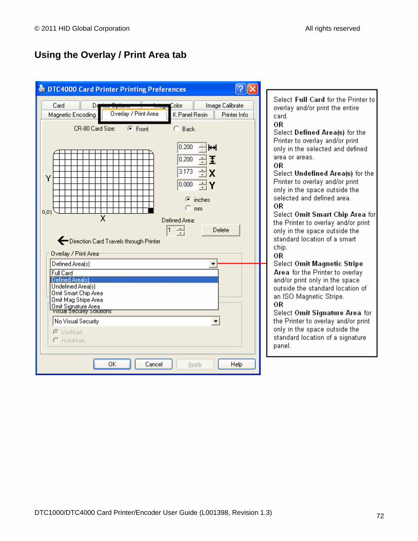
Using the Overlay / Print Area tab
DTC1000/DTC4000 Card Printer/Encoder User Guide (L001398, Revision 1.3) 72

© 2011 HID Global Corporation All rights reserved
Using the Overlay / Print Area tab
DTC1000/DTC4000 Card Printer/Encoder User Guide (L001398, Revision 1.3) 73

© 2011 HID Global Corporation All rights reserved
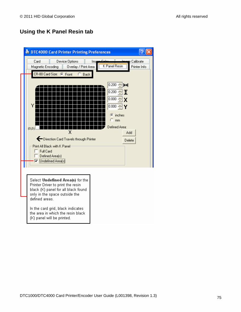
Using the K Panel Resin tab Use this tab to control where the resin black (K) Panel of a full-color Ribbon is printed. Refer to Using the Defined Area Option for a specific procedure that relates to this tab.
DTC1000/DTC4000 Card Printer/Encoder User Guide (L001398, Revision 1.3) 74
© 2011 HID Global Corporation All rights reserved
Using the K Panel Resin tab
DTC1000/DTC4000 Card Printer/Encoder User Guide (L001398, Revision 1.3) 75

© 2011 HID Global Corporation All rights reserved
Using the K Panel Resin tab
DTC1000/DTC4000 Card Printer/Encoder User Guide (L001398, Revision 1.3) 76
© 2011 HID Global Corporation All rights reserved
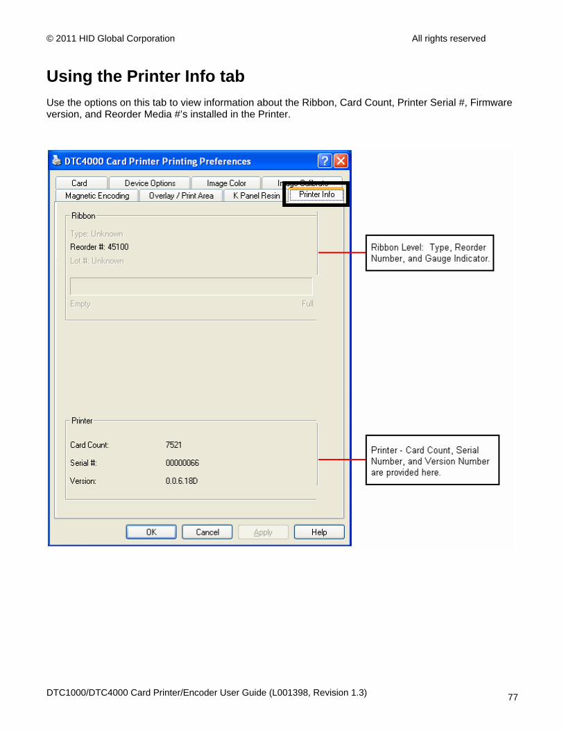
Using the Printer Info tab Use the options on this tab to view information about the Ribbon, Card Count, Printer Serial #, Firmware version, and Reorder Media #’s installed in the Printer.
DTC1000/DTC4000 Card Printer/Encoder User Guide (L001398, Revision 1.3) 77
© 2011 HID Global Corporation All rights reserved
Section 5: Selecting the Fluorescent Panel Ribbon Type (DTC4000 only) The YMCFKO/YMCFKOK Ribbon is an economical way to add a fully customizable, incremental level of security to your photo identification cards.
• Process: This process allows you to configure the data that is printed with the fluorescent panel of an YMCFKO/YMCFKOK Ribbon. (Note: Any software program may be used to print the special florescent panel of the Ribbon to a card once the Driver and Workbench are set up correctly.)
• Ribbons: These Ribbons contain a yellow (Y), magenta (M), cyan (C), and resin black (K) panels to create a full color over-the-edge printing identification card. In addition, the Ribbon contains a dye-based fluorescing panel (F) which will allow you to print a standard or one-to-one personalized fluorescing image that is completely invisible until exposed to ultraviolet light.
Creating a Custom Fluorescent Image (using the YMCFKO Ribbon) There are three (3) methods used to accomplish the creation of a custom fluorescent image when using the YMCFKO Ribbon.
• First Method: The first method uses the Fargo Workbench Printer Utility to create a static image that will be applied automatically to each card sent to the Printer. Refer to the Help file for the Fargo Workbench Utility Program and User Guide or to Appendix A for Configuring Fluorescent Data (F-Panel for YMCFKO Ribbon) using the Workbench.
• Second Method: The second method (described below) allows the creation of the fluorescent panel image directly from the badge application software. (Note: You can now print a unique fluorescent image, such as the card holder’s picture on each card.)
• Third Method: The third method is described in the Asure ID Software User Guide. See the procedure relating to the Fluorescent Panel Ribbon. For more information about , please visit our website at http://www.hidglobal.com/cardIssuance/idSoftware.php
DTC1000/DTC4000 Card Printer/Encoder User Guide (L001398, Revision 1.3) 78
© 2011 HID Global Corporation All rights reserved
Creating a Custom Fluorescent Image (using the YMCFKO Ribbon)
DTC1000/DTC4000 Card Printer/Encoder User Guide (L001398, Revision 1.3) 79
© 2011 HID Global Corporation All rights reserved
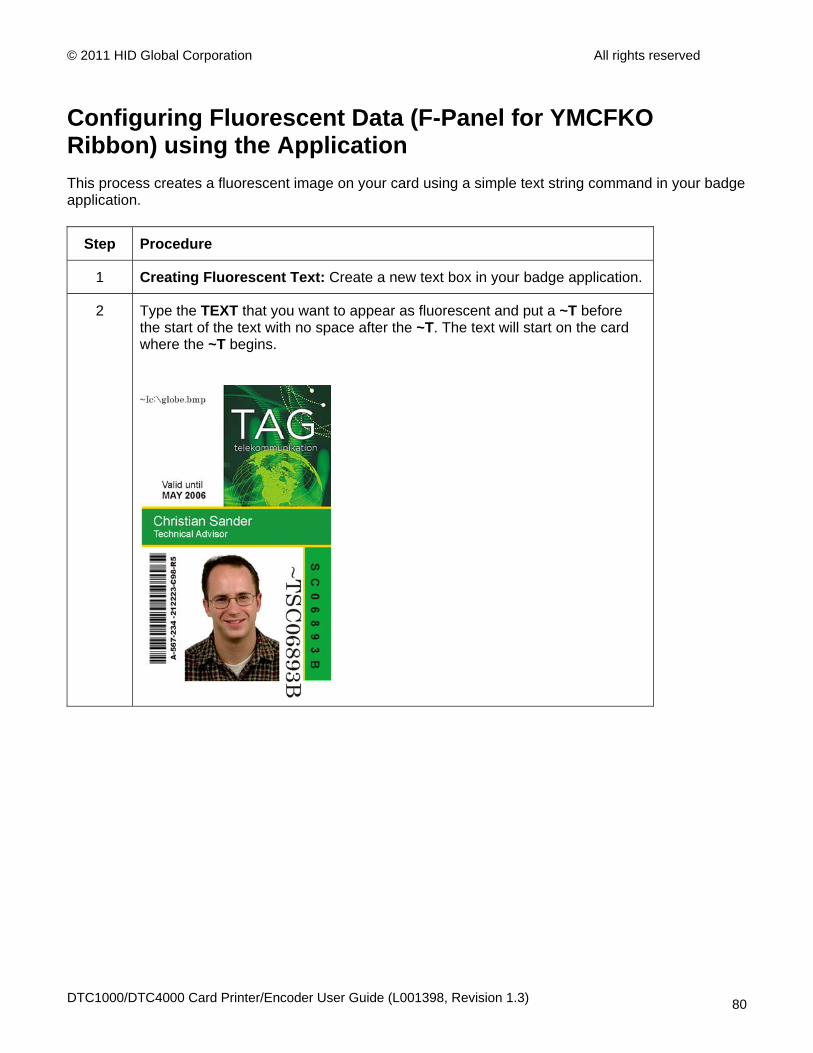
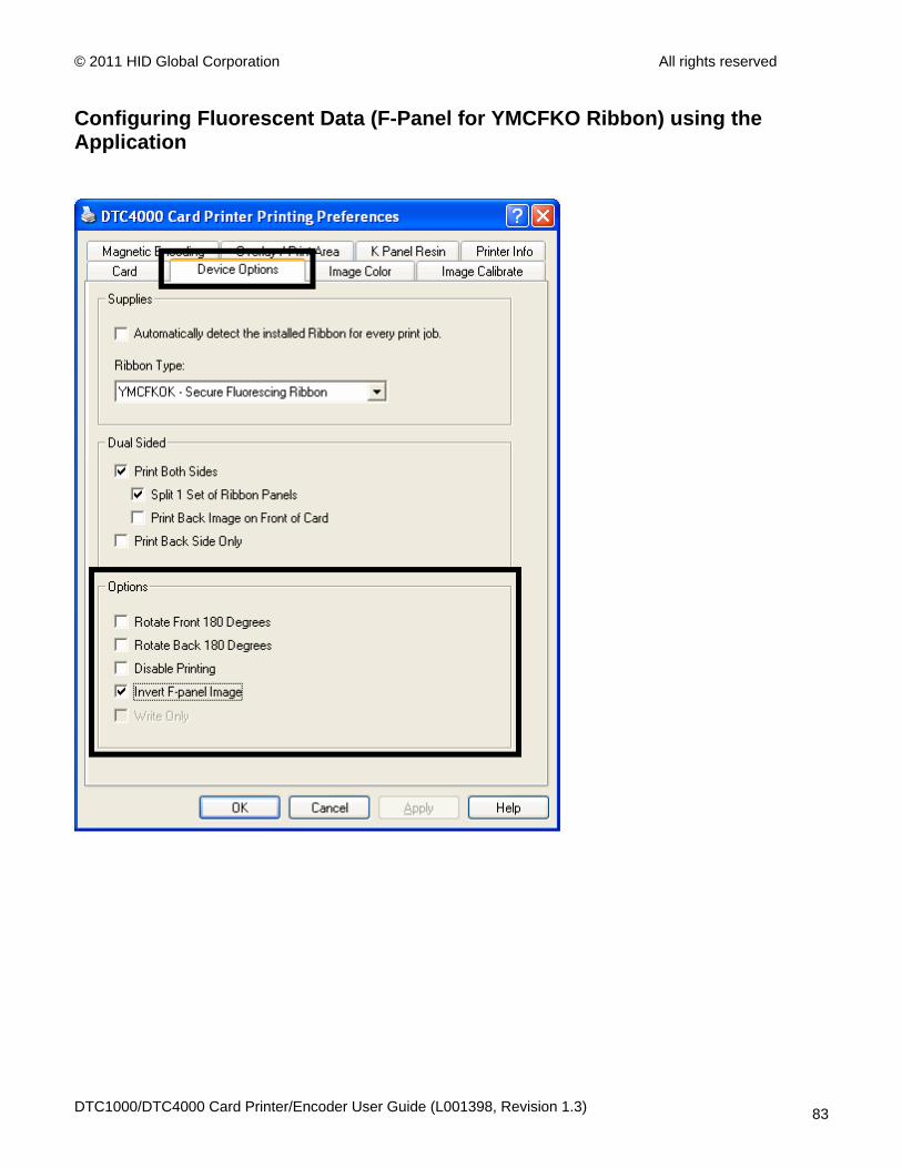
Configuring Fluorescent Data (F-Panel for YMCFKO Ribbon) using the Application This process creates a fluorescent image on your card using a simple text string command in your badge application.
Step Procedure
1 Creating Fluorescent Text: Create a new text box in your badge application.
2 Type the TEXT that you want to appear as fluorescent and put a ~T before the start of the text with no space after the ~T. The text will start on the card where the ~T begins.
DTC1000/DTC4000 Card Printer/Encoder User Guide (L001398, Revision 1.3) 80
© 2011 HID Global Corporation All rights reserved
Configuring Fluorescent Data (F-Panel for YMCFKO Ribbon) using the Application
Step Procedure
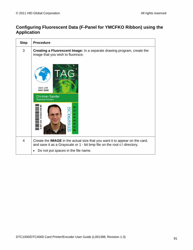
3 Creating a Fluorescent Image: In a separate drawing program, create the image that you wish to fluoresce.
4 Create the IMAGE in the actual size that you want it to appear on the card, and save it as a Grayscale or 1 - bit bmp file on the root c:\ directory.
• Do not put spaces in the file name.
DTC1000/DTC4000 Card Printer/Encoder User Guide (L001398, Revision 1.3) 81

© 2011 HID Global Corporation All rights reserved
Configuring Fluorescent Data (F-Panel for YMCFKO Ribbon) using the Application
Step Procedure
5 Create a new text box in your badge application, and type ~I followed by the address of your image (see Display A below). The top left of your image will start at the top left of your text box.
6 Set up the Printer Driver preferences. Refer to Step 8-9 below.
7 Printer will print the fluorescent BMP IMAGE at the ~I position on the card. Printer will print the fluorescent TEXT at the ~T position on the card.
BMP Image located at c:\globe.bmp
8 Set the Ribbon for YMCFKO in the Printing Preferences. (Note: The Automatically detect the installed Ribbon for every print job button may also be used.)
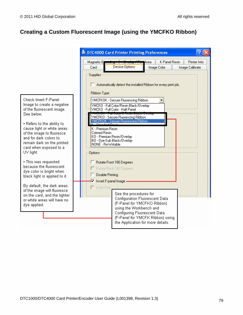
9 Check Invert F-Panel Image to create a negative of the fluorescent image. See below.
• This refers to the ability to cause light or white areas of the image to fluoresce and dark colors to remain dark on the printed card when exposed to a UV light.
• This was requested because the fluorescent dye color is bright when black light is applied to it.
By default, the dark areas of the image will fluoresce on the card and the lighter or white areas will have no dye applied. (Note: This may improve the look of the person’s image if used for the Logo.)
DTC1000/DTC4000 Card Printer/Encoder User Guide (L001398, Revision 1.3) 82
© 2011 HID Global Corporation All rights reserved
Configuring Fluorescent Data (F-Panel for YMCFKO Ribbon) using the Application
DTC1000/DTC4000 Card Printer/Encoder User Guide (L001398, Revision 1.3) 83
© 2011 HID Global Corporation All rights reserved
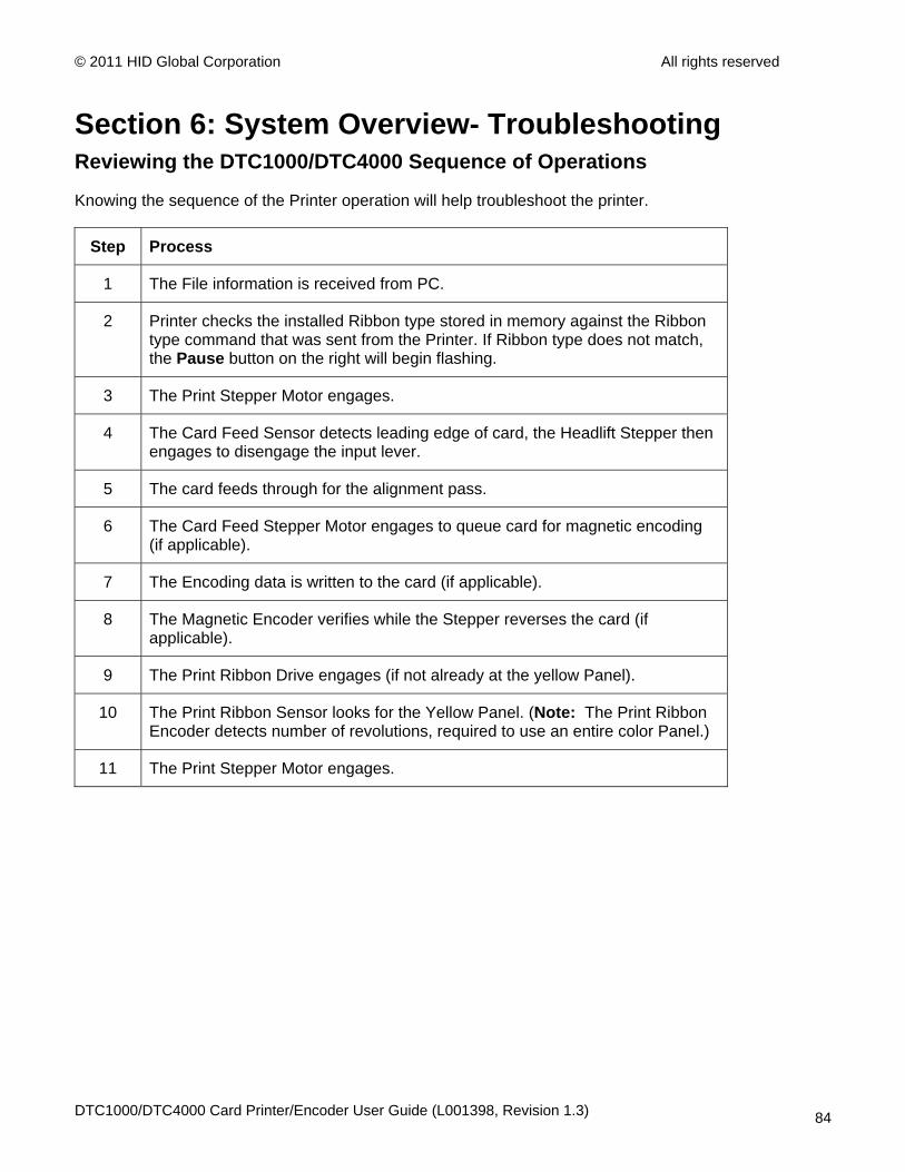
Section 6: System Overview- Troubleshooting Reviewing the DTC1000/DTC4000 Sequence of Operations
Knowing the sequence of the Printer operation will help troubleshoot the printer.
Step Process
1 The File information is received from PC.
2 Printer checks the installed Ribbon type stored in memory against the Ribbon type command that was sent from the Printer. If Ribbon type does not match, the Pause button on the right will begin flashing.
3 The Print Stepper Motor engages.
4 The Card Feed Sensor detects leading edge of card, the Headlift Stepper then engages to disengage the input lever.
5 The card feeds through for the alignment pass.
6 The Card Feed Stepper Motor engages to queue card for magnetic encoding (if applicable).
7 The Encoding data is written to the card (if applicable).
8 The Magnetic Encoder verifies while the Stepper reverses the card (if applicable).
9 The Print Ribbon Drive engages (if not already at the yellow Panel).
10 The Print Ribbon Sensor looks for the Yellow Panel. (Note: The Print Ribbon Encoder detects number of revolutions, required to use an entire color Panel.)
11 The Print Stepper Motor engages.
DTC1000/DTC4000 Card Printer/Encoder User Guide (L001398, Revision 1.3) 84
© 2011 HID Global Corporation All rights reserved
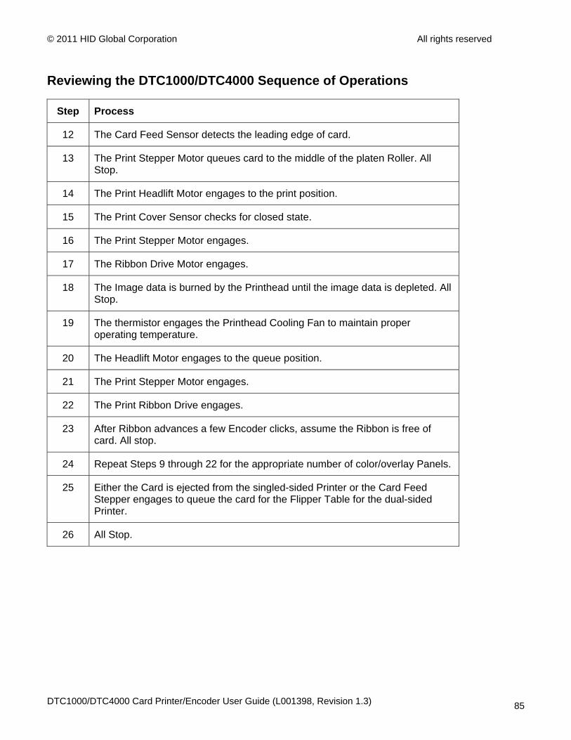
Reviewing the DTC1000/DTC4000 Sequence of Operations
Step Process
12 The Card Feed Sensor detects the leading edge of card.
13 The Print Stepper Motor queues card to the middle of the platen Roller. All Stop.
14 The Print Headlift Motor engages to the print position.
15 The Print Cover Sensor checks for closed state.
16 The Print Stepper Motor engages.
17 The Ribbon Drive Motor engages.
18 The Image data is burned by the Printhead until the image data is depleted. All Stop.
19 The thermistor engages the Printhead Cooling Fan to maintain proper operating temperature.
20 The Headlift Motor engages to the queue position.
21 The Print Stepper Motor engages.
22 The Print Ribbon Drive engages.
23 After Ribbon advances a few Encoder clicks, assume the Ribbon is free of card. All stop.
24 Repeat Steps 9 through 22 for the appropriate number of color/overlay Panels.
25 Either the Card is ejected from the singled-sided Printer or the Card Feed Stepper engages to queue the card for the Flipper Table for the dual-sided Printer.
26 All Stop.
DTC1000/DTC4000 Card Printer/Encoder User Guide (L001398, Revision 1.3) 85
© 2011 HID Global Corporation All rights reserved
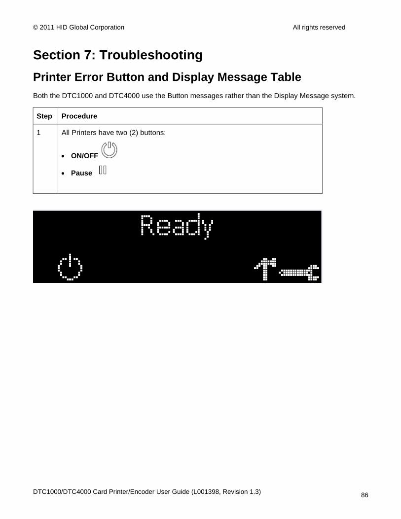
Section 7: Troubleshooting Printer Error Button and Display Message Table Both the DTC1000 and DTC4000 use the Button messages rather than the Display Message system.
Step Procedure
1 All Printers have two (2) buttons:
• ON/OFF
• Pause
DTC1000/DTC4000 Card Printer/Encoder User Guide (L001398, Revision 1.3) 86
© 2011 HID Global Corporation All rights reserved
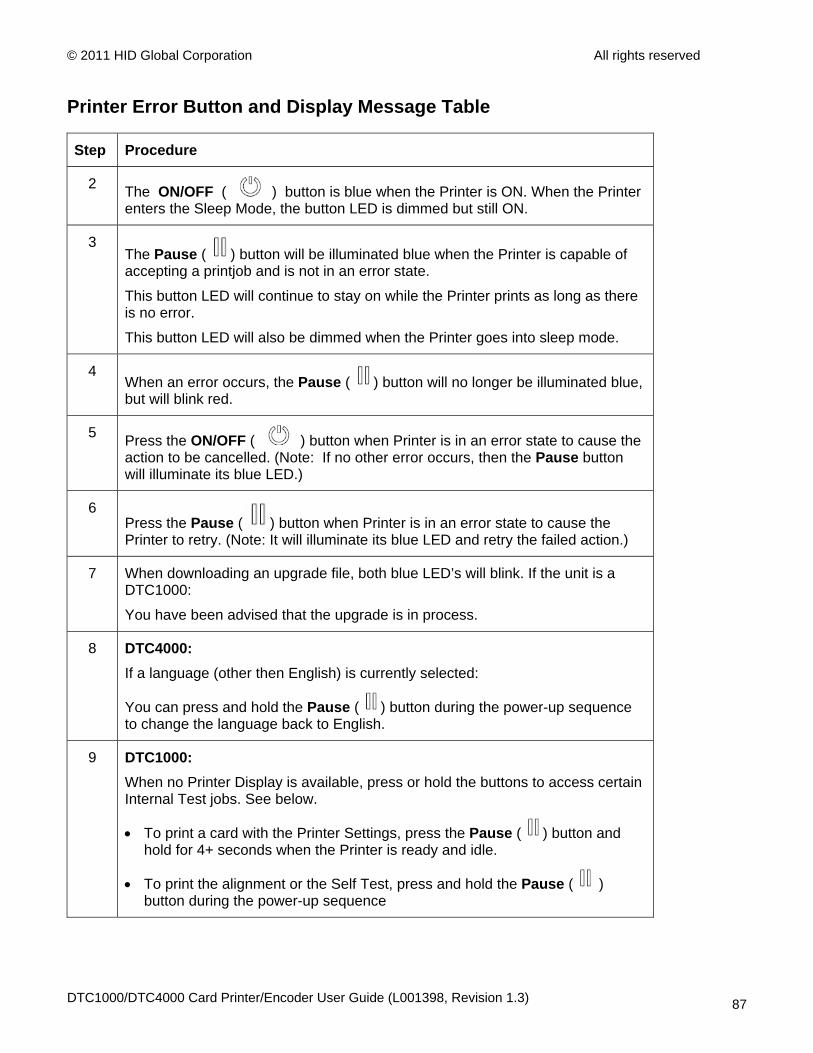
Printer Error Button and Display Message Table
Step Procedure
2 The ON/OFF ( ) button is blue when the Printer is ON. When the Printer enters the Sleep Mode, the button LED is dimmed but still ON.
3 The Pause ( ) button will be illuminated blue when the Printer is capable of accepting a printjob and is not in an error state.
This button LED will continue to stay on while the Printer prints as long as there is no error.
This button LED will also be dimmed when the Printer goes into sleep mode.
4 When an error occurs, the Pause ( ) button will no longer be illuminated blue, but will blink red.
5 Press the ON/OFF ( ) button when Printer is in an error state to cause the action to be cancelled. (Note: If no other error occurs, then the Pause button will illuminate its blue LED.)
6 Press the Pause ( ) button when Printer is in an error state to cause the Printer to retry. (Note: It will illuminate its blue LED and retry the failed action.)
7 When downloading an upgrade file, both blue LED’s will blink. If the unit is a DTC1000:
You have been advised that the upgrade is in process.
8 DTC4000: If a language (other then English) is currently selected:
You can press and hold the Pause ( ) button during the power-up sequence to change the language back to English.
9 DTC1000: When no Printer Display is available, press or hold the buttons to access certain Internal Test jobs. See below.
• To print a card with the Printer Settings, press the Pause ( ) button and hold for 4+ seconds when the Printer is ready and idle.
• To print the alignment or the Self Test, press and hold the Pause ( ) button during the power-up sequence
DTC1000/DTC4000 Card Printer/Encoder User Guide (L001398, Revision 1.3) 87
© 2011 HID Global Corporation All rights reserved
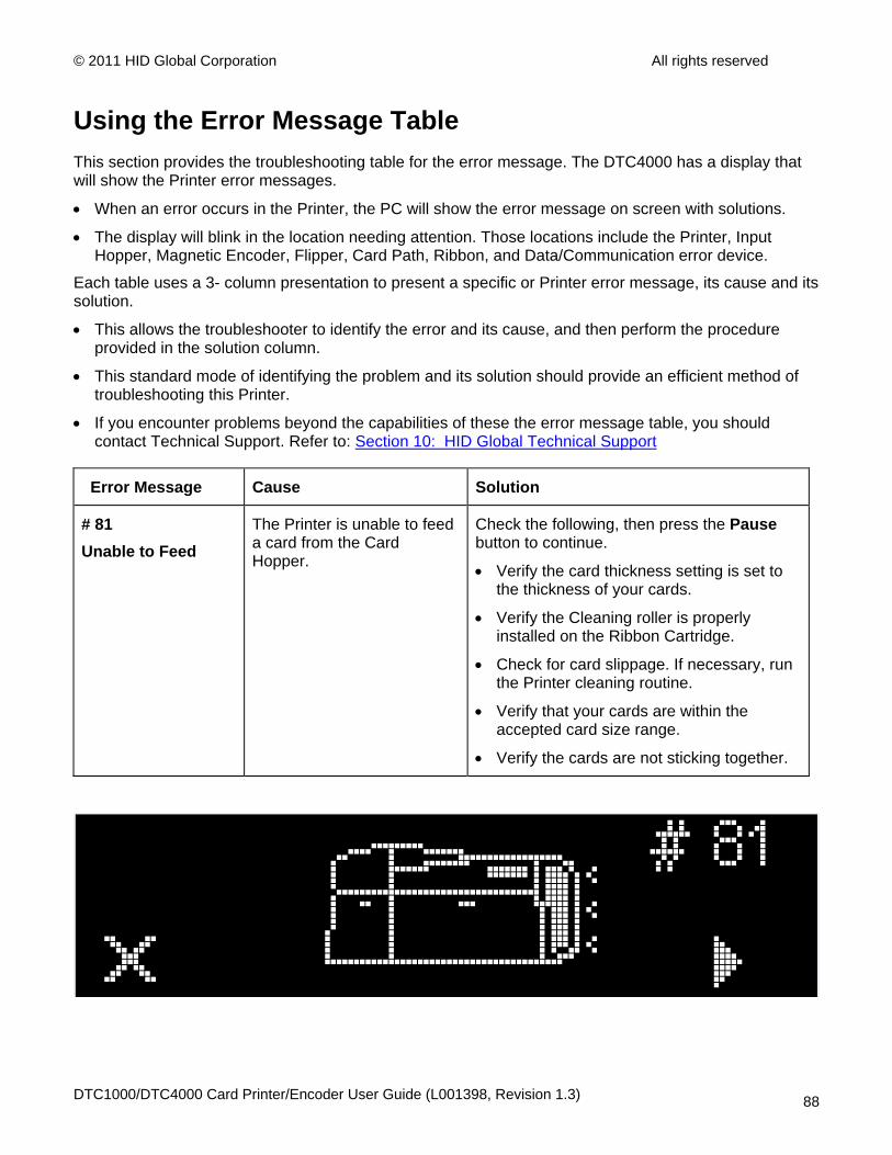
Using the Error Message Table This section provides the troubleshooting table for the error message. The DTC4000 has a display that will show the Printer error messages.
• When an error occurs in the Printer, the PC will show the error message on screen with solutions.
• The display will blink in the location needing attention. Those locations include the Printer, Input Hopper, Magnetic Encoder, Flipper, Card Path, Ribbon, and Data/Communication error device.
Each table uses a 3- column presentation to present a specific or Printer error message, its cause and its solution.
• This allows the troubleshooter to identify the error and its cause, and then perform the procedure provided in the solution column.
• This standard mode of identifying the problem and its solution should provide an efficient method of troubleshooting this Printer.
• If you encounter problems beyond the capabilities of these the error message table, you should contact Technical Support. Refer to: Section 10: HID Global Technical Support
Error Message Cause Solution
# 81 Unable to Feed
The Printer is unable to feed a card from the Card Hopper.
Check the following, then press the Pause button to continue.
• Verify the card thickness setting is set to the thickness of your cards.
• Verify the Cleaning roller is properly installed on the Ribbon Cartridge.
• Check for card slippage. If necessary, run the Printer cleaning routine.
• Verify that your cards are within the accepted card size range.
• Verify the cards are not sticking together.
DTC1000/DTC4000 Card Printer/Encoder User Guide (L001398, Revision 1.3) 88
© 2011 HID Global Corporation All rights reserved
Troubleshooting with the Error Message Table
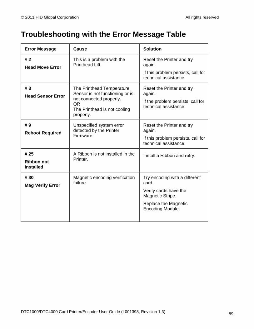
Error Message Cause Solution
# 2 Head Move Error
This is a problem with the Printhead Lift.
Reset the Printer and try again.
If this problem persists, call for technical assistance.
# 8 Head Sensor Error
The Printhead Temperature Sensor is not functioning or is not connected properly. OR The Printhead is not cooling properly.
Reset the Printer and try again.
If the problem persists, call for technical assistance.
# 9 Reboot Required
Unspecified system error detected by the Printer Firmware.
Reset the Printer and try again.
If this problem persists, call for technical assistance.
# 25 Ribbon not Installed
A Ribbon is not installed in the Printer.
Install a Ribbon and retry.
# 30 Mag Verify Error
Magnetic encoding verification failure.
Try encoding with a different card.
Verify cards have the Magnetic Stripe.
Replace the Magnetic Encoding Module.
DTC1000/DTC4000 Card Printer/Encoder User Guide (L001398, Revision 1.3) 89
© 2011 HID Global Corporation All rights reserved
Troubleshooting with the Error Message Table
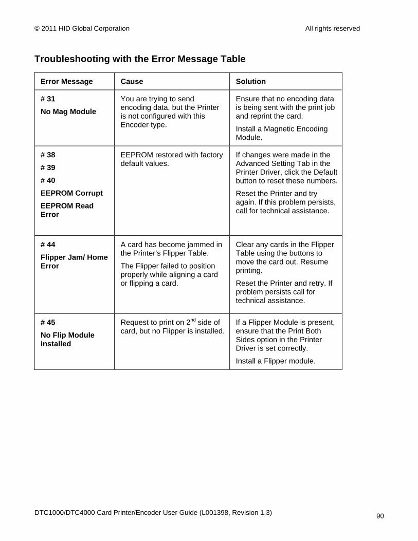
Error Message Cause Solution
# 31 No Mag Module
You are trying to send encoding data, but the Printer is not configured with this Encoder type.
Ensure that no encoding data is being sent with the print job and reprint the card.
Install a Magnetic Encoding Module.
# 38 # 39 # 40 EEPROM Corrupt EEPROM Read Error
EEPROM restored with factory default values.
If changes were made in the Advanced Setting Tab in the Printer Driver, click the Default button to reset these numbers.
Reset the Printer and try again. If this problem persists, call for technical assistance.
# 44 Flipper Jam/ Home Error
A card has become jammed in the Printer’s Flipper Table.
The Flipper failed to position properly while aligning a card or flipping a card.
Clear any cards in the Flipper Table using the buttons to move the card out. Resume printing.
Reset the Printer and retry. If problem persists call for technical assistance.
# 45 No Flip Module installed
Request to print on 2nd side of card, but no Flipper is installed.
If a Flipper Module is present, ensure that the Print Both Sides option in the Printer Driver is set correctly.
Install a Flipper module.
DTC1000/DTC4000 Card Printer/Encoder User Guide (L001398, Revision 1.3) 90

© 2011 HID Global Corporation All rights reserved
Troubleshooting with the Error Message Table
Error Message Cause Solution
# 64 # 65 # 66 Reboot Required
Unspecified system error detected by the Printer Firmware.
Reset the Printer and try again.
If this problem persists, call for technical assistance.
# 68 Card in Printer
A card is jammed in the Print Station or card flipping area of the Printer.
Clear the jam and press the Pause button.
# 70 Multiple Feed
Multiple cards were fed into the Printer.
Verify the card thickness is set to the thickness of your cards, then press the Pause button.
Check for card slippage. If necessary, run the Printer cleaning routine
Verify the Cleaning roller is properly installed on the Ribbon Cartridge.
Verify the cards are not sticking together.
DTC1000/DTC4000 Card Printer/Encoder User Guide (L001398, Revision 1.3) 91
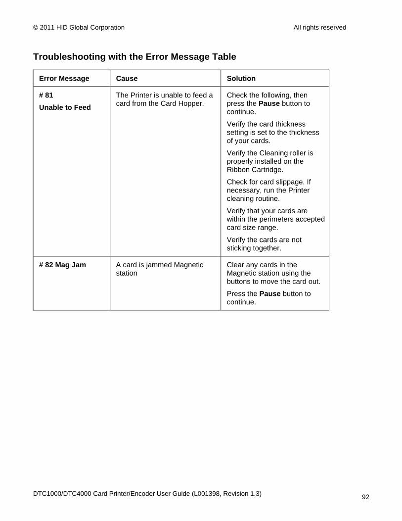
© 2011 HID Global Corporation All rights reserved
Troubleshooting with the Error Message Table
Error Message Cause Solution
# 81 Unable to Feed
The Printer is unable to feed a card from the Card Hopper.
Check the following, then press the Pause button to continue.
Verify the card thickness setting is set to the thickness of your cards.
Verify the Cleaning roller is properly installed on the Ribbon Cartridge.
Check for card slippage. If necessary, run the Printer cleaning routine.
Verify that your cards are within the perimeters accepted card size range.
Verify the cards are not sticking together.
# 82 Mag Jam
A card is jammed Magnetic station
Clear any cards in the Magnetic station using the buttons to move the card out.
Press the Pause button to continue.
DTC1000/DTC4000 Card Printer/Encoder User Guide (L001398, Revision 1.3) 92

© 2011 HID Global Corporation All rights reserved
Troubleshooting with the Error Message Table
Error Message Cause Solution
# 91 Ribbon Out
The Print Ribbon has run out. Install a new Ribbon.
Press the Pause button to continue or the ON/OFF button to cancel.
# 93 Wrong Ribbon
The Print Ribbon installed in the Printer does not match the Ribbon type selected in the Printer Driver.
Change either the installed Print Ribbon or the Ribbon type selected in the Printer Driver.
Press the Pause button to continue or the ON/OFF button to cancel.
# 97 Ribbon Search Error
The Ribbon is not able to find the next panel correctly.
Check for jams/breaks.
Recalibrate the Ribbon Sensor.
If broken, repair by taping the Ribbon back on to the take- up core.
Replace the Ribbon.
Press the Pause button to continue or the ON/OFF button to cancel.
DTC1000/DTC4000 Card Printer/Encoder User Guide (L001398, Revision 1.3) 93
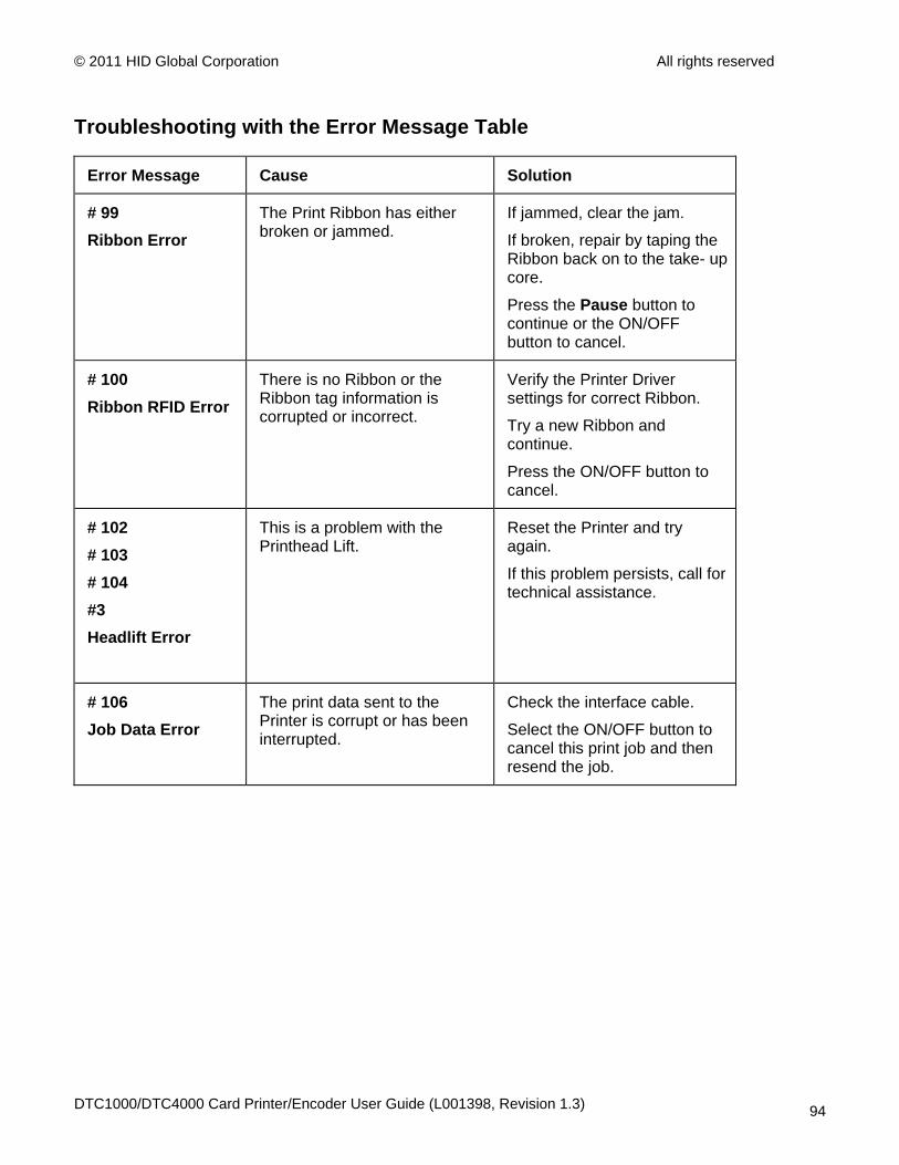
© 2011 HID Global Corporation All rights reserved
Troubleshooting with the Error Message Table
Error Message Cause Solution
# 99 Ribbon Error
The Print Ribbon has either broken or jammed.
If jammed, clear the jam.
If broken, repair by taping the Ribbon back on to the take- up core.
Press the Pause button to continue or the ON/OFF button to cancel.
# 100 Ribbon RFID Error
There is no Ribbon or the Ribbon tag information is corrupted or incorrect.
Verify the Printer Driver settings for correct Ribbon.
Try a new Ribbon and continue.
Press the ON/OFF button to cancel.
# 102 # 103 # 104 #3 Headlift Error
This is a problem with the Printhead Lift.
Reset the Printer and try again.
If this problem persists, call for technical assistance.
# 106 Job Data Error
The print data sent to the Printer is corrupt or has been interrupted.
Check the interface cable.
Select the ON/OFF button to cancel this print job and then resend the job.
DTC1000/DTC4000 Card Printer/Encoder User Guide (L001398, Revision 1.3) 94
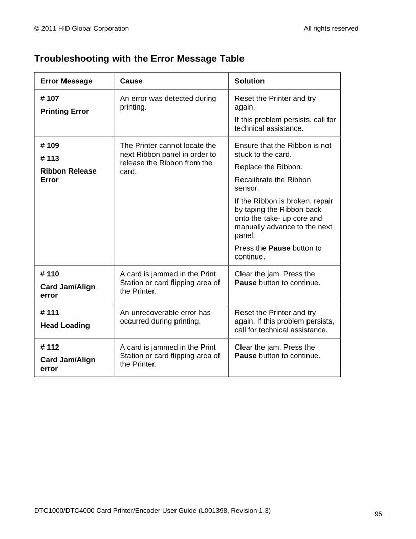
© 2011 HID Global Corporation All rights reserved
Troubleshooting with the Error Message Table
Error Message Cause Solution
# 107 Printing Error
An error was detected during printing.
Reset the Printer and try again.
If this problem persists, call for technical assistance.
# 109 # 113 Ribbon Release Error
The Printer cannot locate the next Ribbon panel in order to release the Ribbon from the card.
Ensure that the Ribbon is not stuck to the card.
Replace the Ribbon.
Recalibrate the Ribbon sensor.
If the Ribbon is broken, repair by taping the Ribbon back onto the take- up core and manually advance to the next panel.
Press the Pause button to continue.
# 110 Card Jam/Align error
A card is jammed in the Print Station or card flipping area of the Printer.
Clear the jam. Press the Pause button to continue.
# 111 Head Loading
An unrecoverable error has occurred during printing.
Reset the Printer and try again. If this problem persists, call for technical assistance.
# 112 Card Jam/Align error
A card is jammed in the Print Station or card flipping area of the Printer.
Clear the jam. Press the Pause button to continue.
DTC1000/DTC4000 Card Printer/Encoder User Guide (L001398, Revision 1.3) 95
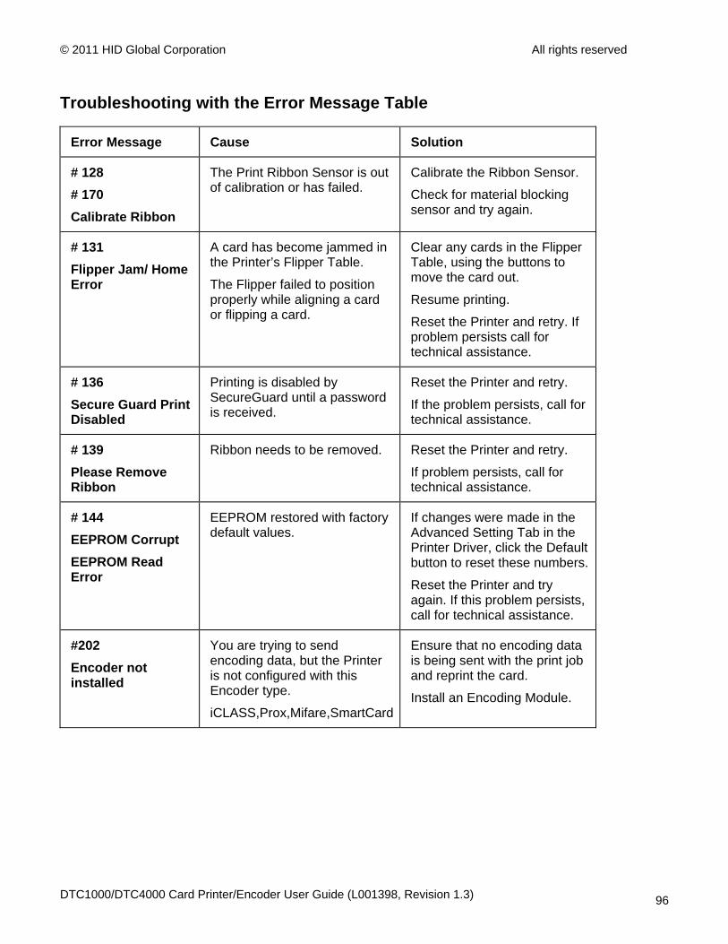
© 2011 HID Global Corporation All rights reserved
Troubleshooting with the Error Message Table
Error Message Cause Solution
# 128 # 170 Calibrate Ribbon
The Print Ribbon Sensor is out of calibration or has failed.
Calibrate the Ribbon Sensor.
Check for material blocking sensor and try again.
# 131 Flipper Jam/ Home Error
A card has become jammed in the Printer’s Flipper Table.
The Flipper failed to position properly while aligning a card or flipping a card.
Clear any cards in the Flipper Table, using the buttons to move the card out.
Resume printing.
Reset the Printer and retry. If problem persists call for technical assistance.
# 136 Secure Guard Print Disabled
Printing is disabled by SecureGuard until a password is received.
Reset the Printer and retry.
If the problem persists, call for technical assistance.
# 139 Please Remove Ribbon
Ribbon needs to be removed. Reset the Printer and retry.
If problem persists, call for technical assistance.
# 144 EEPROM Corrupt EEPROM Read Error
EEPROM restored with factory default values.
If changes were made in the Advanced Setting Tab in the Printer Driver, click the Default button to reset these numbers.
Reset the Printer and try again. If this problem persists, call for technical assistance.
#202 Encoder not installed
You are trying to send encoding data, but the Printer is not configured with this Encoder type.
iCLASS,Prox,Mifare,SmartCard
Ensure that no encoding data is being sent with the print job and reprint the card.
Install an Encoding Module.
DTC1000/DTC4000 Card Printer/Encoder User Guide (L001398, Revision 1.3) 96

© 2011 HID Global Corporation All rights reserved
Printer Specific Tools (DTC1000/DTC4000)
The status icons are as follows:
This icon indicates that the Print Ribbon supply is low and will need to be replaced soon. For the DTC1000 and DTC4000 models, this involves replacing the entire Ribbon Cartridge.
This icon indicates that the Printer needs to be cleaned. Refer to Section 8: Cleaning of the User's Manual.
This icon is only displayed for Printers with an attached Dual-Input Hopper and indicates that the Top Input Hopper is currently selected.
This icon is only displayed for Printers with an attached Dual-Input Hopper and indicates that the Bottom Input Hopper is currently selected.
DTC1000/DTC4000 Card Printer/Encoder User Guide (L001398, Revision 1.3) 97

© 2011 HID Global Corporation All rights reserved
Printer Specific Tools (DTC1000/DTC4000)
Press the button to scroll through the details of the Printer and perform the action.
Press the button to select the option.
Once is selected, use the left down arrow to scroll through the Info, Test Prints, and Languages and Exit.
Use the corner arrow to run that option.
The curved arrow will return to the first screen.
DTC1000/DTC4000 Card Printer/Encoder User Guide (L001398, Revision 1.3) 98

© 2011 HID Global Corporation All rights reserved
Additional Printer Specific Tools
Label Description
INFO • Printer Type
• Firmware Version
• IP Address
• Flipper
• Lamination
• Magnetics
• E-Card
• Password
• Card count
TEST PRINTS
Color Photo: Select this to print a color card to test communication and integrity. Alignment: Select this to print a card used to align the print image on the card. Settings: Select this to print a card with the Advanced settings. Resin: Select this to print a RESIN test card. Rewritable: Select this to ERASE the Rewritable card. Magnetic: Select this to test Magnetic encoding. (Hi-Co only) Lamination: Select this to laminate a test card.
Hopper Select
Ability to select which hopper to feed cards from. Applies to Dual Hopper Printers.
Toolbox Clean Printer: Select this to run the clean printer routine.
Clean Laminator: Select this to run the clean laminator routine.
Calibrate Mag: Select this to calibrate the Magnetic Sensor
DTC1000/DTC4000 Card Printer/Encoder User Guide (L001398, Revision 1.3) 99
© 2011 HID Global Corporation All rights reserved
Calibrate Rib Sensor: Select this to calibrate the ribbon sensor.
Network: Select this to configure network options.
Language Language: Select this choice to change the Printer Displayed Language.
Exit Exit: Select this choice to exit the Printer Tool options.
DTC1000/DTC4000 Card Printer/Encoder User Guide (L001398, Revision 1.3) 100
© 2011 HID Global Corporation All rights reserved
Section 8: Cleaning The Card Printer is built to require a minimum amount of maintenance. Nevertheless, there are a few procedures you can perform on a regular basis or as needed to ensure the best possible performance
Safety Messages (review carefully)
Symbol Critical Instructions for Safety purposes
Danger:
Failure to follow these installation guidelines can result in death or serious injury. Information that raises potential safety issues is indicated by a warning symbol (as shown to the left).
• To prevent personal injury, refer to the following safety messages before performing an operation preceded by this symbol.
• To prevent personal injury, always remove the power cord prior to performing repair procedures, unless otherwise specified.
• To prevent personal injury, make sure only qualified personnel perform these procedures.
Caution:
This device is electrostatically sensitive. It may be damaged if exposed to static electricity discharges. Information that raises potential electrostatic safety issues is indicated by a warning symbol (as shown to the left).
• To prevent equipment or media damage, refer to the following safety messages before performing an operation preceded by this symbol.
• To prevent equipment or media damage, observe all established Electrostatic Discharge (ESD) procedures while handling cables in or near the Circuit Board and Printhead Assemblies.
• To prevent equipment or media damage, always wear an appropriate personal grounding device (e.g., a high quality wrist strap grounded to avoid potential damage).
• To prevent equipment or media damage, always remove the Ribbon and Cards from the Printer before making any repairs, unless otherwise specified.
• To prevent equipment or media damage, take jewelry off of fingers and hands, as well as thoroughly clean hands to remove oil and debris before working on the Printer.
DTC1000/DTC4000 Card Printer/Encoder User Guide (L001398, Revision 1.3) 101
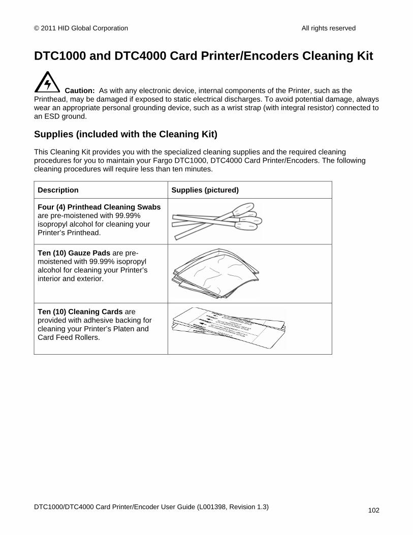
© 2011 HID Global Corporation All rights reserved
DTC1000 and DTC4000 Card Printer/Encoders Cleaning Kit
Caution: As with any electronic device, internal components of the Printer, such as the Printhead, may be damaged if exposed to static electrical discharges. To avoid potential damage, always wear an appropriate personal grounding device, such as a wrist strap (with integral resistor) connected to an ESD ground.
Supplies (included with the Cleaning Kit)
This Cleaning Kit provides you with the specialized cleaning supplies and the required cleaning procedures for you to maintain your Fargo DTC1000, DTC4000 Card Printer/Encoders. The following cleaning procedures will require less than ten minutes.
Description Supplies (pictured)
Four (4) Printhead Cleaning Swabs are pre-moistened with 99.99% isopropyl alcohol for cleaning your Printer’s Printhead.
Ten (10) Gauze Pads are pre-moistened with 99.99% isopropyl alcohol for cleaning your Printer’s interior and exterior.
Ten (10) Cleaning Cards are provided with adhesive backing for cleaning your Printer’s Platen and Card Feed Rollers.
DTC1000/DTC4000 Card Printer/Encoder User Guide (L001398, Revision 1.3) 102
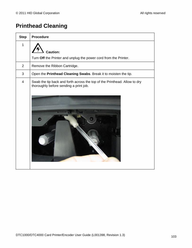
© 2011 HID Global Corporation All rights reserved
Printhead Cleaning
Step Procedure
1
Caution: Turn Off the Printer and unplug the power cord from the Printer.
2 Remove the Ribbon Cartridge.
3 Open the Printhead Cleaning Swabs. Break it to moisten the tip.
4 Swab the tip back and forth across the top of the Printhead. Allow to dry thoroughly before sending a print job.
DTC1000/DTC4000 Card Printer/Encoder User Guide (L001398, Revision 1.3) 103
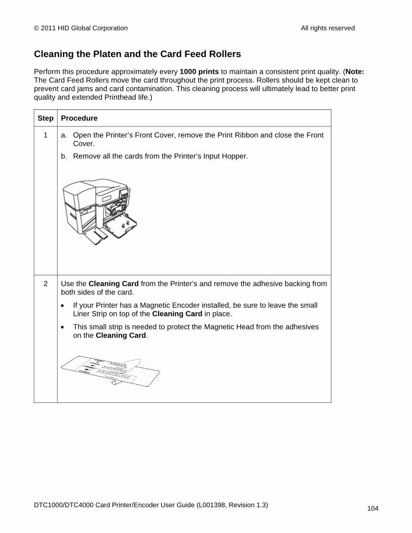
© 2011 HID Global Corporation All rights reserved
Cleaning the Platen and the Card Feed Rollers
Perform this procedure approximately every 1000 prints to maintain a consistent print quality. (Note: The Card Feed Rollers move the card throughout the print process. Rollers should be kept clean to prevent card jams and card contamination. This cleaning process will ultimately lead to better print quality and extended Printhead life.)
Step Procedure
1 a. Open the Printer’s Front Cover, remove the Print Ribbon and close the Front Cover.
b. Remove all the cards from the Printer’s Input Hopper.
2 Use the Cleaning Card from the Printer’s and remove the adhesive backing from both sides of the card.
• If your Printer has a Magnetic Encoder installed, be sure to leave the small Liner Strip on top of the Cleaning Card in place.
• This small strip is needed to protect the Magnetic Head from the adhesives on the Cleaning Card.
DTC1000/DTC4000 Card Printer/Encoder User Guide (L001398, Revision 1.3) 104

© 2011 HID Global Corporation All rights reserved
Cleaning the Platen and the Card Feed Rollers
Step Procedure
3 Insert the Cleaning Card into the Single Feed Card Slot until the card stops.
If your Printer is equipped with a Magnetic Encoder, you must insert the Cleaning Card with the printed side up and with the small Liner Strip towards the front of the Printer.
4 From your computer, open the Printer Driver and select Printing Preferences.
DTC1000/DTC4000 Card Printer/Encoder User Guide (L001398, Revision 1.3) 105
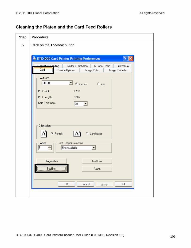
© 2011 HID Global Corporation All rights reserved
Cleaning the Platen and the Card Feed Rollers
Step Procedure
5 Click on the Toolbox button.
DTC1000/DTC4000 Card Printer/Encoder User Guide (L001398, Revision 1.3) 106

© 2011 HID Global Corporation All rights reserved
Cleaning the Platen and the Card Feed Rollers
Step Procedure
6 Click on the Clean Printer button.
7 Click on the Clean button (shown above).
• The Printer will pull in the Cleaning Card. The Printer will then perform an automated cleaning procedure.
• This procedure is designed to thoroughly clean the Platen and the Card Feed Rollers inside the Printer.
DTC1000/DTC4000 Card Printer/Encoder User Guide (L001398, Revision 1.3) 107
© 2011 HID Global Corporation All rights reserved
Cleaning the Printer’s Interior Periodically, use a Cleaning Pad from the Printer’s Cleaning Kit to remove dust and other contaminants from inside the Printer. (Note: Dust and other particles may accumulate inside the Printer with continued usage. This can cause spots or specks to appear on the printed cards.)
Cleaning the Printer’s Exterior Clean it only with a Cleaning Pad from the Printer’s Cleaning Kit. (Note: The Printer has a durable casing that should retain its luster and appearance for many years.
DTC1000/DTC4000 Card Printer/Encoder User Guide (L001398, Revision 1.3) 108
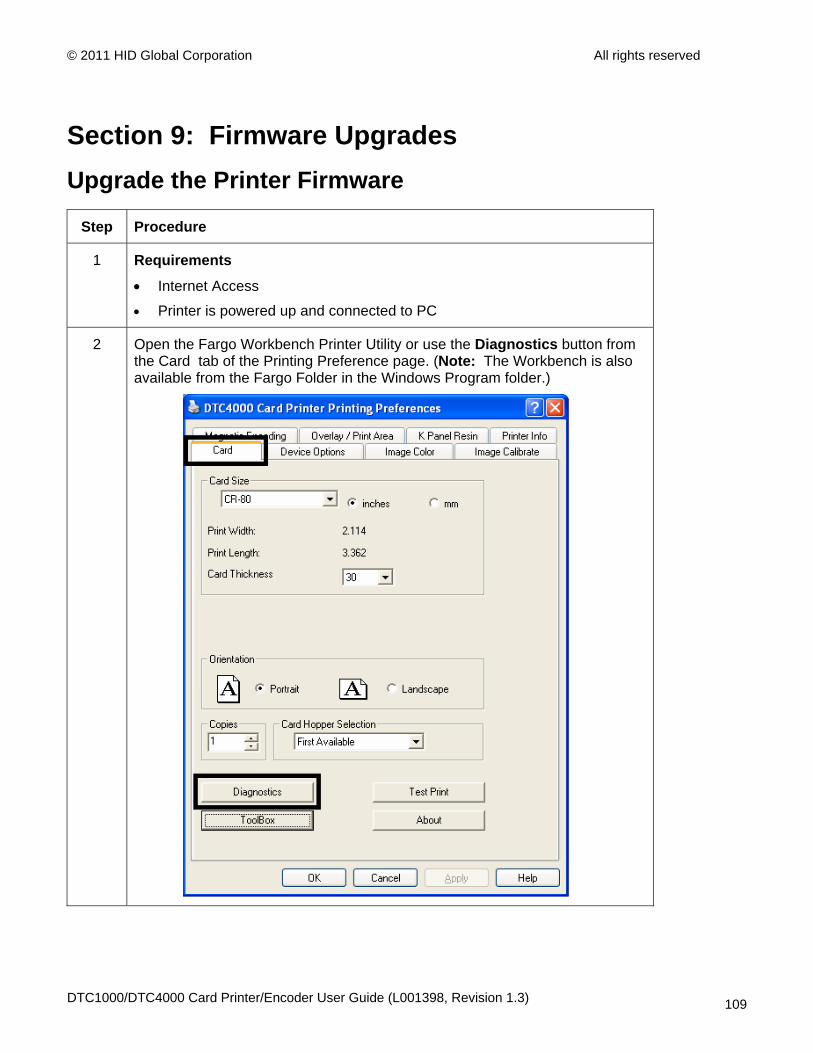
© 2011 HID Global Corporation All rights reserved
Section 9: Firmware Upgrades Upgrade the Printer Firmware
Step Procedure
1 Requirements
• Internet Access
• Printer is powered up and connected to PC
2 Open the Fargo Workbench Printer Utility or use the Diagnostics button from the Card tab of the Printing Preference page. (Note: The Workbench is also available from the Fargo Folder in the Windows Program folder.)
DTC1000/DTC4000 Card Printer/Encoder User Guide (L001398, Revision 1.3) 109

© 2011 HID Global Corporation All rights reserved
Upgrade the Printer Firmware
Step Procedure
3 From the Application Icon, select Upgrade Firmware.
4 Find the Firmware via Check for Firmware Updates at www.hidglobal.com
• Save the file to a folder. (Double-Click the file to Un-Zip the file)
• Use the Browse button to find the .frm file.
• Select the file. Click Open.
DTC1000/DTC4000 Card Printer/Encoder User Guide (L001398, Revision 1.3) 110
© 2011 HID Global Corporation All rights reserved
5 Click on Upgrade to start the upgrade process.
6 This message will appear while the Firmware is updating.
LOADING FIRMWARE
7 The Printer will reboot after this process is completed.
DTC1000/DTC4000 Card Printer/Encoder User Guide (L001398, Revision 1.3) 111
© 2011 HID Global Corporation All rights reserved
Section 10: HID Global Technical Support The purpose of this section to provide you with an efficient, step-by-step procedure to be used when contacting HID GLOBAL Technical Support as needed for this Card Printer.
Step Procedure
1 Contact the HID Global Technical Support Group by phone at (866)607-7339 Ext #6 or by fax at (952) 946-8492 for additional technical assistance.
OR
Contact HID Technical Support via the Web: www.hidglobal.com
2 Position a phone near the Printer and Computer so the technician can help to troubleshoot the Printer(s).
3 Please have a self-test and a sample card ready when calling HID Technical Support.
DTC1000/DTC4000 Card Printer/Encoder User Guide (L001398, Revision 1.3) 112
© 2011 HID Global Corporation All rights reserved
Reading the Serial Numbers on a Fargo Printer You can determine when your card Printer was manufactured by reading directly from the serial number (affixed to your card Printer).
Example Explanation
Reviewing Example No. 1: Serial Number A9050028 ( 2009)
• A9050028: The first two digits in the serial number indicate the year the Printer was built (e.g., the digits A9 indicate the year 2009).
• A9050028: The third and fourth digits in the serial number indicate the week the Printer was built (e.g., the digits 05 indicate week 5 of that year).
• A9050028: The last four digits indicate the sequence number for the numeric order in which the Printers were built.
Reviewing Example No. 2: Serial Number B0050028 (2010)
• B0050028: The first two digits in the serial number indicate the year the Printer was built (e.g., the digits B0 indicate the year 2010).
• B0050028: The third and fourth digits in the serial number indicate the week the Printer was built (e.g., the digits 05 indicate week 5 of that year).
• B0050028: The last four digits indicate the sequence number for the numeric order in which the Printers were built.
DTC1000/DTC4000 Card Printer/Encoder User Guide (L001398, Revision 1.3) 113
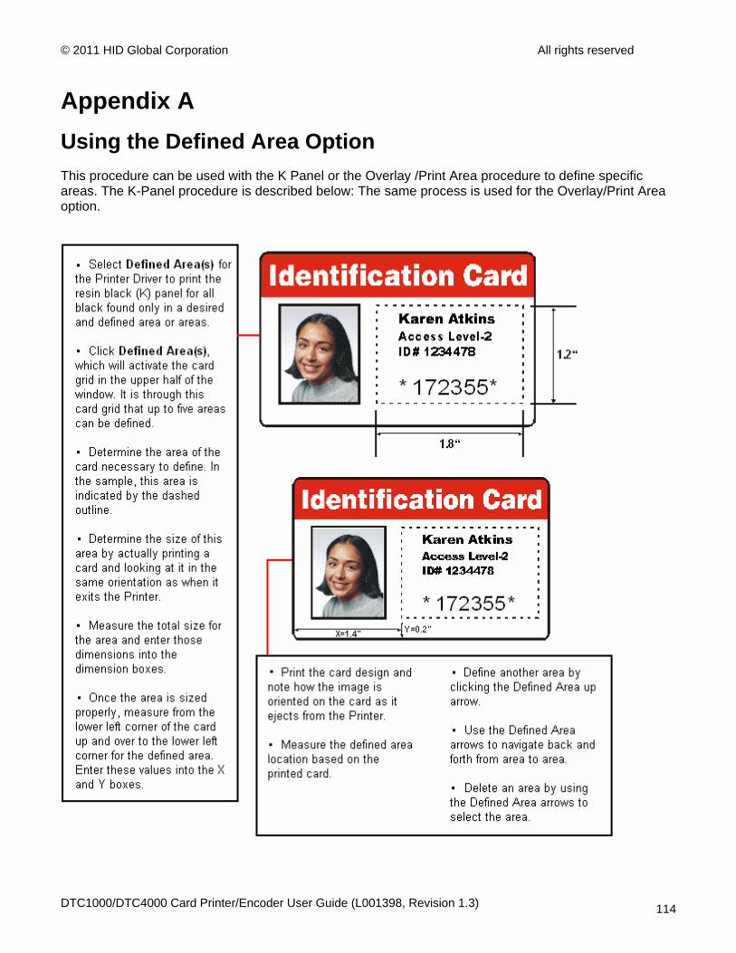
© 2011 HID Global Corporation All rights reserved
Appendix A Using the Defined Area Option This procedure can be used with the K Panel or the Overlay /Print Area procedure to define specific areas. The K-Panel procedure is described below: The same process is used for the Overlay/Print Area option.
DTC1000/DTC4000 Card Printer/Encoder User Guide (L001398, Revision 1.3) 114
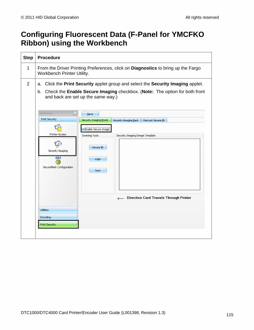
© 2011 HID Global Corporation All rights reserved
Configuring Fluorescent Data (F-Panel for YMCFKO Ribbon) using the Workbench
Step Procedure
1 From the Driver Printing Preferences, click on Diagnostics to bring up the Fargo Workbench Printer Utility.
2 a. Click the Print Security applet group and select the Security Imaging applet.
b. Check the Enable Secure Imaging checkbox. (Note: The option for both front and back are set up the same way.)
DTC1000/DTC4000 Card Printer/Encoder User Guide (L001398, Revision 1.3) 115
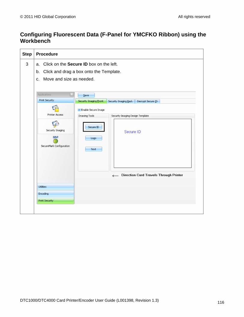
© 2011 HID Global Corporation All rights reserved
Configuring Fluorescent Data (F-Panel for YMCFKO Ribbon) using the Workbench
Step Procedure
3 a. Click on the Secure ID box on the left.
b. Click and drag a box onto the Template.
c. Move and size as needed.
DTC1000/DTC4000 Card Printer/Encoder User Guide (L001398, Revision 1.3) 116
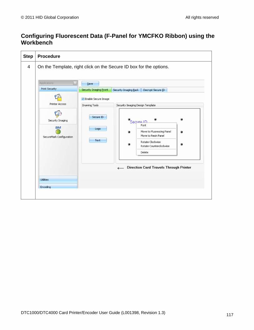
© 2011 HID Global Corporation All rights reserved
Configuring Fluorescent Data (F-Panel for YMCFKO Ribbon) using the Workbench
Step Procedure
4 On the Template, right click on the Secure ID box for the options.
DTC1000/DTC4000 Card Printer/Encoder User Guide (L001398, Revision 1.3) 117

© 2011 HID Global Corporation All rights reserved
Configuring Fluorescent Data (F-Panel for YMCFKO Ribbon) using the Workbench
Step Procedure
5 a. Click on the Logo box on the left.
b. Click and drag a box onto the Template.
c. Move and size (as needed) by grabbing the corner of the box.
DTC1000/DTC4000 Card Printer/Encoder User Guide (L001398, Revision 1.3) 118

© 2011 HID Global Corporation All rights reserved
Configuring Fluorescent Data (F-Panel for YMCFKO Ribbon) using the Workbench
Step Procedure
6 On the Template right click on the Logo box for the options shown below.
7 Select the Logo File.
Find the source of the Logo to place on the card. (Note: Fit to Frame will size the image to fit the box. Once this is set up, this logo will print from the software program. This is set up in the background.)
DTC1000/DTC4000 Card Printer/Encoder User Guide (L001398, Revision 1.3) 119
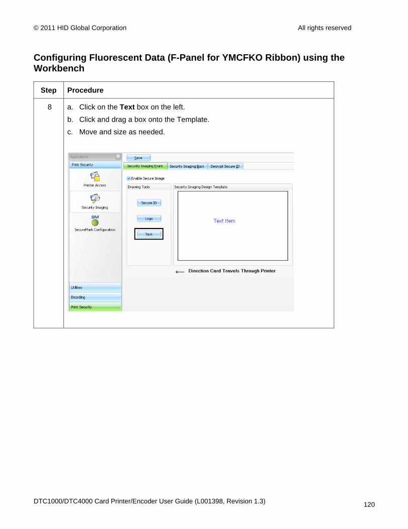
© 2011 HID Global Corporation All rights reserved
Configuring Fluorescent Data (F-Panel for YMCFKO Ribbon) using the Workbench
Step Procedure
8 a. Click on the Text box on the left.
b. Click and drag a box onto the Template.
c. Move and size as needed.
DTC1000/DTC4000 Card Printer/Encoder User Guide (L001398, Revision 1.3) 120
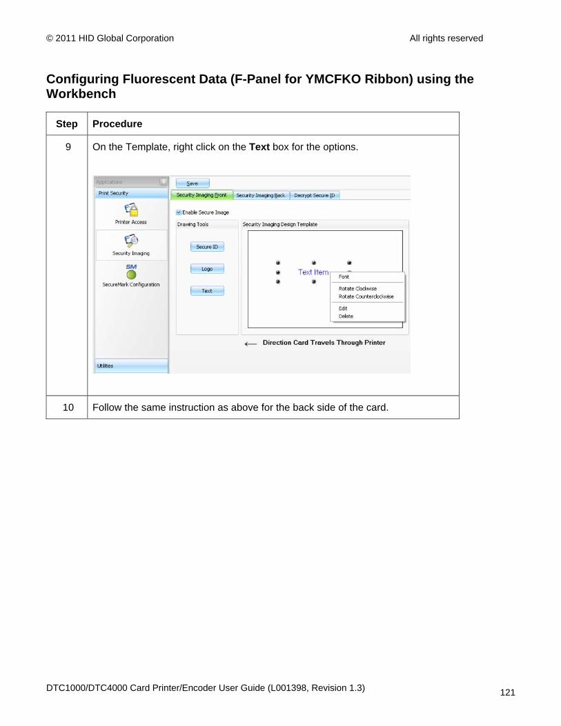
© 2011 HID Global Corporation All rights reserved
Configuring Fluorescent Data (F-Panel for YMCFKO Ribbon) using the Workbench
Step Procedure
9 On the Template, right click on the Text box for the options.
10 Follow the same instruction as above for the back side of the card.
DTC1000/DTC4000 Card Printer/Encoder User Guide (L001398, Revision 1.3) 121
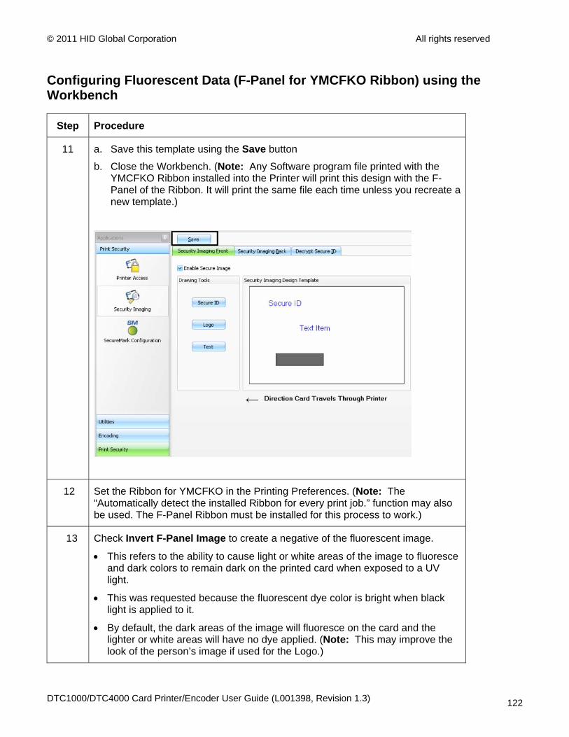
© 2011 HID Global Corporation All rights reserved
Configuring Fluorescent Data (F-Panel for YMCFKO Ribbon) using the Workbench
Step Procedure
11 a. Save this template using the Save button
b. Close the Workbench. (Note: Any Software program file printed with the YMCFKO Ribbon installed into the Printer will print this design with the F-Panel of the Ribbon. It will print the same file each time unless you recreate a new template.)
12 Set the Ribbon for YMCFKO in the Printing Preferences. (Note: The “Automatically detect the installed Ribbon for every print job.” function may also be used. The F-Panel Ribbon must be installed for this process to work.)
13 Check Invert F-Panel Image to create a negative of the fluorescent image.
• This refers to the ability to cause light or white areas of the image to fluoresce and dark colors to remain dark on the printed card when exposed to a UV light.
• This was requested because the fluorescent dye color is bright when black light is applied to it.
• By default, the dark areas of the image will fluoresce on the card and the lighter or white areas will have no dye applied. (Note: This may improve the look of the person’s image if used for the Logo.)
DTC1000/DTC4000 Card Printer/Encoder User Guide (L001398, Revision 1.3) 122

© 2011 HID Global Corporation All rights reserved
DTC1000/DTC4000 Card Printer/Encoder User Guide (L001398, Revision 1.3) 123
Configuring Fluorescent Data (F-Panel for YMCFKO Ribbon) using the Workbench


![User Guide...User. {{]}]} {}]}](https://img.pdfslide.us/doc/110x75/60918ca14327954d24291644/-user-guide-user-.jpg)