Embed Size (px)
Citation preview
2003 Microchip Technology Inc. DS51425A
dsPICDEM™
STARTER DEMO BOARD
USER’S GUIDE

Note the following details of the code protection feature on Microchip devices:
• Microchip products meet the specification contained in their particular Microchip Data Sheet.
• Microchip believes that its family of products is one of the most secure families of its kind on the market today, when used in the
intended manner and under normal conditions.
• There are dishonest and possibly illegal methods used to breach the code protection feature. All of these methods, to our
knowledge, require using the Microchip products in a manner outside the operating specifications contained in Microchip's Data
Sheets. Most likely, the person doing so is engaged in theft of intellectual property.
• Microchip is willing to work with the customer who is concerned about the integrity of their code.
• Neither Microchip nor any other semiconductor manufacturer can guarantee the security of their code. Code protection does not
mean that we are guaranteeing the product as “unbreakable.”
Code protection is constantly evolving. We at Microchip are committed to continuously improving the code protection features of our
products. Attempts to break microchip’s code protection feature may be a violation of the Digital Millennium Copyright Act. If such acts
allow unauthorized access to your software or other copyrighted work, you may have a right to sue for relief under that Act.
Information contained in this publication regarding device
applications and the like is intended through suggestion only
and may be superseded by updates. It is your responsibility to
ensure that your application meets with your specifications.
No representation or warranty is given and no liability is
assumed by Microchip Technology Incorporated with respect
to the accuracy or use of such information, or infringement of
patents or other intellectual property rights arising from such
use or otherwise. Use of Microchip’s products as critical
components in life support systems is not authorized except
with express written approval by Microchip. No licenses are
conveyed, implicitly or otherwise, under any intellectual
property rights.
DS51425A-page ii
Trademarks
The Microchip name and logo, the Microchip logo, Accuron,
dsPIC, KEELOQ, MPLAB, PIC, PICmicro, PICSTART,
PRO MATE and PowerSmart are registered trademarks of
Microchip Technology Incorporated in the U.S.A. and other
countries.
AmpLab, FilterLab, microID, MXDEV, MXLAB, PICMASTER,
SEEVAL and The Embedded Control Solutions Company are
registered trademarks of Microchip Technology Incorporated
in the U.S.A.
Application Maestro, dsPICDEM, dsPICDEM.net, ECAN,
ECONOMONITOR, FanSense, FlexROM, fuzzyLAB,
In-Circuit Serial Programming, ICSP, ICEPIC, microPort,
Migratable Memory, MPASM, MPLIB, MPLINK, MPSIM,
PICkit, PICDEM, PICDEM.net, PowerCal, PowerInfo,
PowerMate, PowerTool, rfLAB, rfPIC, Select Mode,
SmartSensor, SmartShunt, SmartTel and Total Endurance are
trademarks of Microchip Technology Incorporated in the
U.S.A. and other countries.
Serialized Quick Turn Programming (SQTP) is a service mark
of Microchip Technology Incorporated in the U.S.A.
All other trademarks mentioned herein are property of their
respective companies.
© 2003, Microchip Technology Incorporated, Printed in the
U.S.A., All Rights Reserved.
Printed on recycled paper.
2003 Microchip Technology Inc.
Microchip received QS-9000 quality system certification for its worldwide headquarters, design and wafer fabrication facilities in Chandler and Tempe, Arizona in July 1999 and Mountain View, California in March 2002. The Company’s quality system processes and procedures are QS-9000 compliant for its PICmicro® 8-bit MCUs, KEELOQ® code hopping devices, Serial EEPROMs, microperipherals, non-volatile memory and analog products. In addition, Microchip’s quality system for the design and manufacture of development systems is ISO 9001 certified.
dsPICDEM™ STARTER
DEMO BOARD USER’S GUIDETable of Contents
Preface ........................................................................................................................... 1
Chapter 1. Introduction
1.1 Introduction ..................................................................................................... 7
1.2 Highlights ........................................................................................................ 7
1.3 dsPICDEM Starter Demo Board Kit Contents ................................................ 7
1.4 dsPICDEM Starter Demo Board Functionality and Features ......................... 8
1.5 dsPICDEM Starter Demo Board Demonstration Program ............................. 9
1.6 Reference Documents .................................................................................... 9
Chapter 2. Tutorial
2.1 Introduction ................................................................................................... 11
2.2 Highlights ...................................................................................................... 11
2.3 Tutorial Overview ......................................................................................... 11
2.4 Creating the Project ...................................................................................... 12
2.5 Building the Code ......................................................................................... 16
2.6 Programming the Chip ................................................................................. 19
2.7 Debugging the Code .................................................................................... 22
2.8 Summary ...................................................................................................... 24
Chapter 3. Demonstration Program Operation
3.1 Introduction ................................................................................................... 25
3.2 Highlights ...................................................................................................... 25
3.3 Demonstration Program Summary ............................................................... 25
3.4 Demonstration Code Operation .................................................................... 27
3.5 Board Self Test ............................................................................................. 30
Chapter 4. dsPICDEM™ Development Hardware
4.1 dsPICDEM™ Starter Demo Board Hardware Overview .............................. 33
Appendix A. Drawings and Schematics
A.1 dsPICDEM Starter Demo Board Layout ...................................................... 37
A.2 dsPICDEM Starter Demo Board Schematic ................................................ 38
Index ............................................................................................................................. 43
Worldwide Sales and Service .................................................................................... 48
2003 Microchip Technology Inc. DS51425A-page iii

dsPICDEM™ Starter Demo Board User’s Guide
NOTES:
DS51425A-page iv 2003 Microchip Technology Inc.
dsPICDEM™ STARTER
DEMO BOARD USER’S GUIDEPreface
INTRODUCTION
This chapter contains general information about this user’s guide and available customer support that will be useful prior to using the dsPICDEM™ Starter Demo Board.
HIGHLIGHTS
Items discussed in this chapter are:
• About this Guide
• Warranty Registration
• Recommended Reading
• The Microchip Web Site
• Development Systems Customer Change Notification Service
• Customer Support
ABOUT THIS GUIDE
This user’s guide describes how to use the dsPICDEM Starter Demo Board. The document is organized as follows:
• Chapter 1: Introduction – This chapter introduces the dsPICDEM Starter Demo Board and provides a brief description of the hardware.
• Chapter 2: Tutorial – This chapter details the step-by-step process for getting the dsPICDEM Starter Demo Board up and running with the MPLAB® In-Circuit Debugger 2 (ICD 2).
• Chapter 3: Demonstration Program Operation – This chapter describes the operational functionality of the sample code that is preprogrammed into the dsPIC30F device.
• Chapter 4: dsPICDEM™ Development Hardware – This chapter describes the hardware comprising the dsPICDEM Starter Demo Board.
• Appendix A: Hardware Schematics – This appendix provides dsPICDEM Starter Demo Board hardware layout and schematic diagrams.
2003 Microchip Technology Inc. DS51425A-page 1
dsPICDEM™ Starter Demo Board User’s Guide
Conventions Used in This Guide
This manual uses the following documentation conventions:
TABLE 1: DOCUMENTATION CONVENTIONS
Documentation Updates
All documentation becomes dated, and this document is no exception. Since Microchip tools are constantly evolving to meet customer needs, some actual dialogs and/or tool descriptions may differ from those in this document. Please refer to our web site to obtain the latest documentation available.
Documentation Numbering Conventions
Documents are numbered with a “DS” number. The number is located on the bottom of each page, in front of the page number. The numbering convention for the DS Number is: DSXXXXXA;
where:
WARRANTY REGISTRATION
Please complete the enclosed Warranty Registration Card and mail it promptly. Sending in the Warranty Registration Card entitles user’s to receive new product updates. Interim software releases are available on the Microchip web site.
Description Represents Examples
Code (Courier font):
Plain characters Sample code
Filenames and paths
#define STARTc:\autoexec.bat
Square brackets [ ] Optional arguments pic30-as [main.s]
Curly brackets and pipe
character: |
Choice of mutually exclusive
arguments; an OR selection
errorlevel 0|1
Ellipses... Used to imply (but not show)
additional text that is not relevant to
the example
list
["list_option..., "list_option"]
0xnnnn A hexadecimal number where n is a
hexadecimal digit
0xFFFF, 0x007A
Italic characters A variable argument; it can be either a
type of data (in lower case characters)
or a specific example (in upper case
characters)
pic30-gcc filename
Interface (Arial font):
Underlined, italic text
with right arrow
A menu selection from the menu bar File > Save
Bold characters A window or dialog button to click OK, Cancel
Characters in angle
brackets < >
A key on the keyboard <Tab>, <Ctrl-C>
Documents (Arial font):
Italic characters Referenced books MPLAB IDE User’s Guide
XXXXX = The document number.
A = The revision level of the document.
DS51425A-page 2 2003 Microchip Technology Inc.
Preface
RECOMMENDED READING
This user’s guide describes how to use the dsPICDEM Starter Demo Board. Other useful documents include:
dsPIC30F Family Reference Manual (DS70046)
Consult this document for detailed information on dsPIC30F device operation. This reference manual explains the operation of the dsPIC30F MCU family architecture and peripheral modules but does not cover the specifics of each device. Refer to the appropriate device data sheet for device-specific information.
dsPIC30F Data Sheet, Motor Control and Power Conversion Family (DS70082)
Consult this document for detailed information on the dsPIC30F Motor Control and Power Conversion devices. Reference information found in this data sheet includes:
• Device memory map
• Device pinout and packaging details
• Device electrical specifications
• List of peripherals included on the device
dsPIC30F Data Sheet, General Purpose and Sensor Families (DS70083)
Consult this document for detailed information on the dsPIC30F Sensor and General Purpose devices. Reference information found in this data sheet includes:
• Device memory map
• Device pinout and packaging details
• Device electrical specifications
• List of peripherals included on the device
dsPIC30F Programmer’s Reference Manual (DS70030)
This manual is a software developer’s reference for the dsPIC30F 16-bit MCU family of devices. It describes the instruction set in detail and also provides general information to assist in developing software for the dsPIC30F MCU family.
dsPIC30F Family Overview (DS70043)
This document provides an overview of the functionality of the dsPIC® product family. It helps determine how the dsPIC 16-bit Digital Signal Controller Family fits a specific product application. This document is a supplement to the dsPIC30F Family Reference
Manual.
MPLAB ASM30, MPLAB LINK30 and Utilities User’s Guide (DS51317)
This document details Microchip Technology’s language tools for dsPIC devices based on GNU technology. The language tools discussed are:
• MPLAB ASM30 Assembler
• MPLAB LINK30 Linker
• MPLAB LIB30 Archiver/Librarian
• Other Utilities
2003 Microchip Technology Inc. DS51425A-page 3

dsPICDEM™ Starter Demo Board User’s Guide
MPLAB C30 C Compiler User’s Guide and Libraries (DS51284)
This document details the use of Microchip’s MPLAB C30 C Compiler for dsPIC devices to develop an application. MPLAB C30 is a GNU-based language tool, based on source code from the Free Software Foundation (FSF). For more information about the FSF, see www.fsf.org.
Other GNU language tools available from Microchip are:
• MPLAB ASM30 Assembler
• MPLAB LINK30 Linker
• MPLAB LIB30 Librarian/Archiver
MPLAB IDE Simulator, Editor User’s Guide (DS51025)
Consult this document for more information pertaining to the installation and implementation of the MPLAB Integrated Development Environment (IDE) Software.
To obtain any of these documents, contact the nearest Microchip sales location (see back page) or visit the Microchip web site at www.microchip.com.
THE MICROCHIP WEB SITE
Microchip provides online support on the Microchip World Wide Web (WWW) site. The web site is used by Microchip as a means to make files and information easily available to customers. To view the site, you must have access to the Internet and a web browser, such as, Netscape Navigator® or Microsoft® Internet Explorer.
The Microchip web site is available by using your favorite Internet browser to reach:
http://www.microchip.com
The web site provides a variety of services. Users may download files for the latest development tools, data sheets, application notes, user’s guides, articles and sample programs. A variety of information specific to the business of Microchip is also available, including listings of Microchip sales offices, distributors and factory representatives.
Technical Support
• Frequently Asked Questions (FAQ)
• Online Discussion Groups – conferences for products, development systems, technical information and more
• Microchip Consultant Program Member Listing
• Links to other useful web sites related to Microchip products
Engineer’s Toolbox
• Design Tips
• Device Errata
Other Available Information
• Latest Microchip Press Releases
• Listing of seminars and events
• Job Postings
DS51425A-page 4 2003 Microchip Technology Inc.
Preface
DEVELOPMENT SYSTEMS CUSTOMER NOTIFICATION SERVICE
Microchip started the customer notification service to help our customers keep current on Microchip products with the least amount of effort. Once you subscribe, you will receive e-mail notification whenever we change, update, revise or have errata related to a specified product family or development tool of interest.
Go to the Microchip web site at (http://www.microchip.com) and click on Customer Change Notification. Follow the instructions to register.
The Development Systems product group categories are:
• Compilers
• Emulators
• In-Circuit Debuggers
• MPLAB IDE
• Programmers
Here is a description of these categories:
Compilers – The latest information on Microchip C compilers and other language tools. These include the MPLAB® C17, MPLAB C18 and MPLAB C30 C compilers; MPASM™ and MPLAB ASM30 assemblers; MPLINK™ and MPLAB LINK30 object linkers; MPLIB™ and MPLAB LIB30 object librarians.
Emulators – The latest information on Microchip in-circuit emulators. This includes the MPLAB ICE 2000 and MPLAB ICE 4000.
In-Circuit Debuggers – The latest information on Microchip in-circuit debuggers. These include the MPLAB ICD and MPLAB ICD 2.
MPLAB IDE – The latest information on Microchip MPLAB IDE, the Windows Integrated Development Environment for development systems tools. This list is focused on the MPLAB IDE, MPLAB SIM and MPLAB SIM30 simulators, MPLAB IDE Project Manager and general editing and debugging features.
Programmers – The latest information on Microchip device programmers. These include the PRO MATE® II device programmer and PICSTART® Plus development programmer.
2003 Microchip Technology Inc. DS51425A-page 5
dsPICDEM™ Starter Demo Board User’s Guide
CUSTOMER SUPPORT
Users of Microchip products can receive assistance through several channels:
• Distributor or Representative
• Local Sales Office
• Field Application Engineer (FAE)
• Corporate Applications Engineer (CAE)
• Hotline
Customers should call their distributor, representative or field application engineer (FAE) for support. Local sales offices are also available to help customers. See the back cover for a list of sales offices and locations.
Corporate Applications Engineers (CAEs) may be contacted at (480) 792-7627.
In addition, there is a Systems Information and Upgrade Line. This line provides system users a list of the latest versions of all of Microchip’s development systems software products. Plus, this line provides information on how customers can receive any currently available upgrade kits.
The Hotline Numbers are:
1-800-755-2345 for U.S. and most of Canada.
1-480-792-7302 for the rest of the world.
DS51425A-page 6 2003 Microchip Technology Inc.

dsPICDEM™ STARTER
DEMO BOARD USER’S GUIDEChapter 1. Introduction
1.1 INTRODUCTION
The dsPICDEM Starter Demo Board serves as a development kit and evaluation tool for the dsPIC30F High Performance Digital Signal Controllers.
1.2 HIGHLIGHTS
This chapter discusses:
• dsPICDEM Starter Demo Board Kit Contents
• dsPICDEM Starter Demo Board Functionality and Features
• dsPICDEM Starter Demo Board Demonstration Program
• Reference documents
1.3 dsPICDEM STARTER DEMO BOARD KIT CONTENTS
The following items comprise the dsPICDEM Starter Demo Board Kit:
• The dsPICDEM Starter Demo Board printed circuit board (see Figure 1-1).
• A preprogrammed dsPIC30F6012 device soldered onto an adapter board that plugs into the Emulation Header on the dsPICDEM Starter Demo Board (see Figure 1-2). (Some early versions of the dsPICDEM Starter Demo Board may have the dsPIC30F device soldered onto the main board.)
• dsPICDEM Starter Demo Board CD-ROM containing various demonstration programs provided by Microchip.
FIGURE 1-1: dsPICDEM STARTER DEMO BOARD
2003 Microchip Technology Inc. DS51425A-page 7

dsPICDEM™ Starter Demo Board User’s Guide
FIGURE 1-2: TYPICAL PREPROGRAMMED DEVICE ADAPTER BOARD
For information on the components used on the dsPICDEM Starter Demo Board see Chapter 4. “dsPICDEM™ Development Hardware”.
1.4 dsPICDEM STARTER DEMO BOARD FUNCTIONALITY AND FEATURES
The dsPICDEM Starter Demo Board provides the following capabilities:
Development Board Power
• On-board +5V regulator for VDD and AVDD with direct input from 9V, AC/DC wall adapter
• 9 VDC power source input jack for development board
• Power-on indicator LED
MPLAB ICD 2 and MPLAB ICE 4000 Connections
• MPLAB ICD 2 programming connector
• Emulation header for connection to MPLAB ICE 4000
• Pad location for 64-pin TQFP dsPIC device
Serial Communication Channel
• Single RS-232 communication channel
Analog
• One 10 kΩ Potentiometer (RP2)
• Microchip MCP41010 Digital Potentiometer
• Microchip MCP6022 Operational Amplifier
- Output configured as low-pass filter for digital potentiometer
- Input configured as low-pass filter for sampling input signals with the ADC
Device Clocking
• 4.0 MHz crystal (Y1) for dsPIC device
Miscellaneous
• Reset push button switch (S3) for resetting the dsPIC device
• Four red LEDs (RD4-RD7)
• Two push button switches (S1-S2) for external input stimulus
• Prototype area for user hardware
DS51425A-page 8 2003 Microchip Technology Inc.
Introduction
1.5 dsPICDEM STARTER DEMO BOARD DEMONSTRATION PROGRAM
The dsPICDEM Starter Demo Board is supplied with a pre-loaded demonstration program that exercises principal CPU functions and peripheral options that allow interaction with the program as follows:
• Demonstrates interrupt handling by using switches S1 and S2 to blink LEDs RD4 and RD5, respectively.
• Demonstrates digital-to-analog conversion by manipulating an audio tone on LINE OUT.
• Demonstrates analog-to-digital conversion by adjusting Potentiometer RP2 and transmitting the resulting digital value to the HyperTerminal on a PC.
Refer to Chapter 3. “Demonstration Program Operation” for details on the demonstration code operation.
1.6 REFERENCE DOCUMENTS
The following documentation is available to support the use of the dsPICDEM Starter Demo Board:
• dsPIC30F Family Reference Manual (DS70046)
• dsPIC30F Family Reference Manual Errata (DS80169)
• dsPIC30F Data Sheet, Motor Control and Power Conversion Family (DS70082)
• dsPIC30F Data Sheet, General Purpose and Sensor Families (DS70083)
• dsPIC30F Programmer’s Reference Manual (DS70030)
• dsPIC30F Programmer’s Reference Manual Errata (DS80170)
• dsPIC30F Family Overview (DS70043)
• MPLAB C30 C Compiler User’s Guide and Libraries (DS51284)
• MPLAB ASM30, MPLAB LINK30 and Utilities User’s Guide (DS51317)
• MPLAB ICD 2 In-Circuit Debugger Quick Start Guide (DS51268)
• MPLAB ICE Emulator User’s Guide (DS51159)
You can obtain these reference documents from your nearest Microchip sales office (listed in the back of this document) or by downloading them from the Microchip web site (www.microchip.com).
2003 Microchip Technology Inc. DS51425A-page 9

dsPICDEM™ Starter Demo Board User’s Guide
NOTES:
DS51425A-page 10 2003 Microchip Technology Inc.

dsPICDEM™ STARTER
DEMO BOARD USER’S GUIDEChapter 2. Tutorial
2.1 INTRODUCTION
This chapter is a self-paced tutorial to get you started using the dsPICDEM Starter Demo Board.
2.2 HIGHLIGHTS
Items discussed in this chapter include:
• Tutorial Overview
• Creating the Project
• Building the Code
• Programming the Chip
• Debugging the Code
• Summary
2.3 TUTORIAL OVERVIEW
The tutorial program in Eg1_BlinkLed.s is written in assembly code. This program blinks an LED when a key is pressed. The source file is used with a linker script file (p30f6012.gld) and an include file (p30f6012.inc) to form a complete project. This simple project uses a single source code file; however, more complex projects might use multiple assembler and compiler source files as well as library files and precompiled object files.
There are four steps to this tutorial:
1. Creating a project in MPLAB IDE.
2. Assembling and linking the code.
3. Programming the chip with the MPLAB ICD 2.
4. Debugging the code with the MPLAB ICD 2.
2003 Microchip Technology Inc. DS51425A-page 11
dsPICDEM™ Starter Demo Board User’s Guide
2.4 CREATING THE PROJECT
The first step is to create a project and a workspace in MPLAB IDE. Typically, there is one project in one workspace.
A project contains the files needed to build an application (source code, linker script files, etc.) along with their associations to various build tools and build options.
A workspace contains one or more projects and information on the selected device, debug tool and/or programmer, open windows and their location and other IDE configuration settings.
MPLAB IDE contains a Project Wizard to help create new projects. Before starting, create a folder named Tutorial for the project files for this tutorial (C:\Tutorial is assumed in the instructions that follow). From the Example Code\Tutorial Code directory on the Development Kit Software CD-ROM, copy the Eg1_BlinkLed.s file into this folder.
2.4.1 Select a Device
1. Start MPLAB IDE.
2. Close any workspace that might be open (File>Close Workspace).
3. From the Project menu, select Project Wizard.
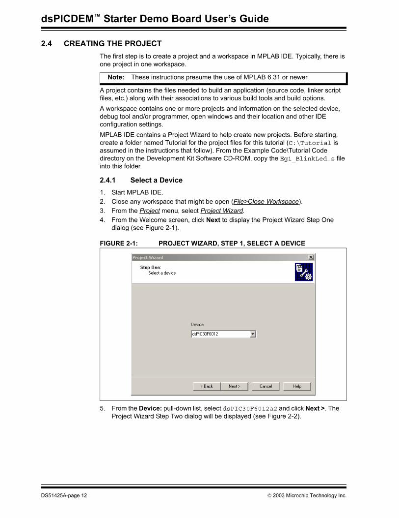
4. From the Welcome screen, click Next to display the Project Wizard Step One dialog (see Figure 2-1).
FIGURE 2-1: PROJECT WIZARD, STEP 1, SELECT A DEVICE
5. From the Device: pull-down list, select dsPIC30F6012a2 and click Next >. The Project Wizard Step Two dialog will be displayed (see Figure 2-2).
Note: These instructions presume the use of MPLAB 6.31 or newer.
DS51425A-page 12 2003 Microchip Technology Inc.
Tutorial
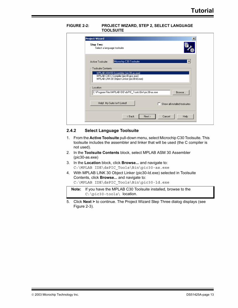
FIGURE 2-2: PROJECT WIZARD, STEP 2, SELECT LANGUAGE
TOOLSUITE
2.4.2 Select Language Toolsuite
1. From the Active Toolsuite pull-down menu, select Microchip C30 Toolsuite. This toolsuite includes the assembler and linker that will be used (the C compiler is not used).
2. In the Toolsuite Contents block, select MPLAB ASM 30 Assembler (pic30-as.exe)
3. In the Location block, click Browse... and navigate to:C:\MPLAB IDE\dsPIC_Tools\Bin\pic30-as.exe
4. With MPLAB LINK 30 Object Linker (pic30-Id.exe) selected in Toolsuite Contents, click Browse... and navigate to:C:\MPLAB IDE\dsPIC_Tools\Bin\pic30-ld.exe
5. Click Next > to continue. The Project Wizard Step Three dialog displays (see Figure 2-3).
Note: If you have the MPLAB C30 Toolsuite installed, browse to the C:\pic30-tools\ location.
2003 Microchip Technology Inc. DS51425A-page 13
dsPICDEM™ Starter Demo Board User’s Guide
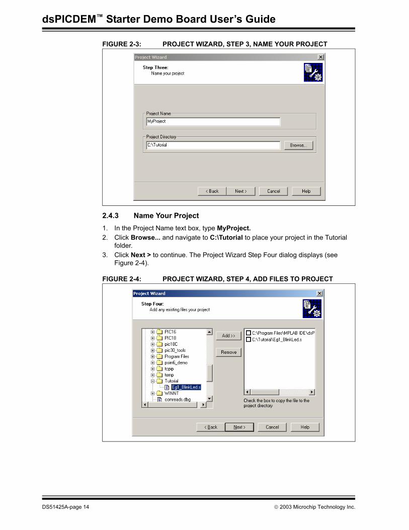
FIGURE 2-3: PROJECT WIZARD, STEP 3, NAME YOUR PROJECT
2.4.3 Name Your Project
1. In the Project Name text box, type MyProject.
2. Click Browse... and navigate to C:\Tutorial to place your project in the Tutorial folder.
3. Click Next > to continue. The Project Wizard Step Four dialog displays (see Figure 2-4).
FIGURE 2-4: PROJECT WIZARD, STEP 4, ADD FILES TO PROJECT
DS51425A-page 14 2003 Microchip Technology Inc.
Tutorial
2.4.4 Add Files to Project
1. From the list of folders on the PC, locate the C:\Tutorial folder and select the Eg1_BlinkLed.s file.
2. Click Add>> to include the file in the project.
3. Expand the C:\MPLAB IDE\dsPIC_Tools\support\gld folder and select the p30f6012.gld file.
4. Click Add>> to include this file in the project. There should now be two files in the project.
5. Click Next > to continue.
6. When the summary screen displays, click Finish.
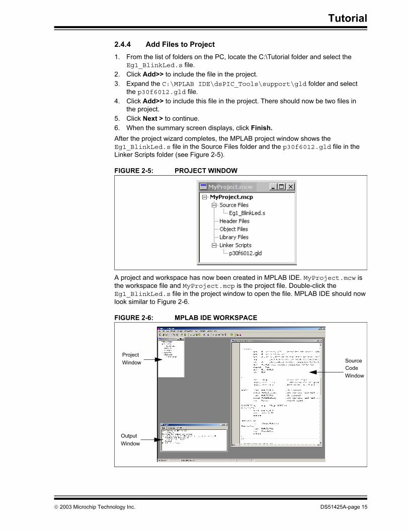
After the project wizard completes, the MPLAB project window shows the Eg1_BlinkLed.s file in the Source Files folder and the p30f6012.gld file in the Linker Scripts folder (see Figure 2-5).
FIGURE 2-5: PROJECT WINDOW
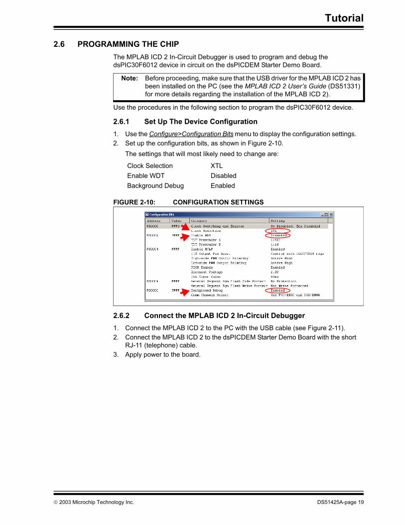
A project and workspace has now been created in MPLAB IDE. MyProject.mcw is the workspace file and MyProject.mcp is the project file. Double-click the Eg1_BlinkLed.s file in the project window to open the file. MPLAB IDE should now look similar to Figure 2-6.
FIGURE 2-6: MPLAB IDE WORKSPACE
Project
Window
Output
Window
Source
Window
Code
2003 Microchip Technology Inc. DS51425A-page 15

dsPICDEM™ Starter Demo Board User’s Guide
2.5 BUILDING THE CODE
In this project, building the code consists of assembling the Eg1_BlinkLed.s file to create an object file Eg1_BlinkLed.o and then linking the object file to create the
Eg1_BlinkLed.hex and Eg1_BlinkLed.cof output files. The HEX file contains the data necessary to program the device, and the .cof file contains additional information that lets you debug the code at the source code level.
Before building, there are settings required to tell MPLAB IDE where to find the include files and to reserve space for the extra debug code when the MPLAB ICD 2 is used.
The following line is near the top of the Eg1_BlinkLed.s file:
.include "p30f6012.inc"
This line causes a standard include file to be used. Microchip provides these files with all the special function register (SFR) labels already defined for convenience.
To build the code, select Build Options>Project from the Project menu. The Build Options dialog displays (see Figure 2-7).
FIGURE 2-7: BUILD OPTIONS
Browse to the location of the
Assembler Include file
DS51425A-page 16 2003 Microchip Technology Inc.

Tutorial
2.5.1 Identify Assembler Include Path
1. Select the General tab.
2. At the Assembler Include Path, $(AINDIR):box, click Browse... and navigate to:
C:\MPLAB IDE\dsPIC_Tools\support\inc
This path tells MPLAB IDE where to find the include files.
3. Select the MPLAB LINK30 tab to view the linker settings (see Figure 2-8).
FIGURE 2-8: MPLAB LINK30 BUILD OPTIONS
2.5.2 Link for MPLAB ICD 2
1. Check Link for ICD 2.
2. Click OK. The text box closes while the linker reserves space for the debug code used by the MPLAB ICD 2.
3. Click OK again to save these changes. The project is now ready to build.
Check Link for ICD2
2003 Microchip Technology Inc. DS51425A-page 17

dsPICDEM™ Starter Demo Board User’s Guide
2.5.3 Build the Project
1. From the Project menu, select Make. The Build Output window displays.
2. Observe the progress of the build.
3. When the BUILD SUCCEEDED message displays (see Figure 2-9) you are ready to program the device.
FIGURE 2-9: BUILD OUTPUT
DS51425A-page 18 2003 Microchip Technology Inc.
Tutorial
2.6 PROGRAMMING THE CHIP
The MPLAB ICD 2 In-Circuit Debugger is used to program and debug the dsPIC30F6012 device in circuit on the dsPICDEM Starter Demo Board.
Use the procedures in the following section to program the dsPIC30F6012 device.
2.6.1 Set Up The Device Configuration
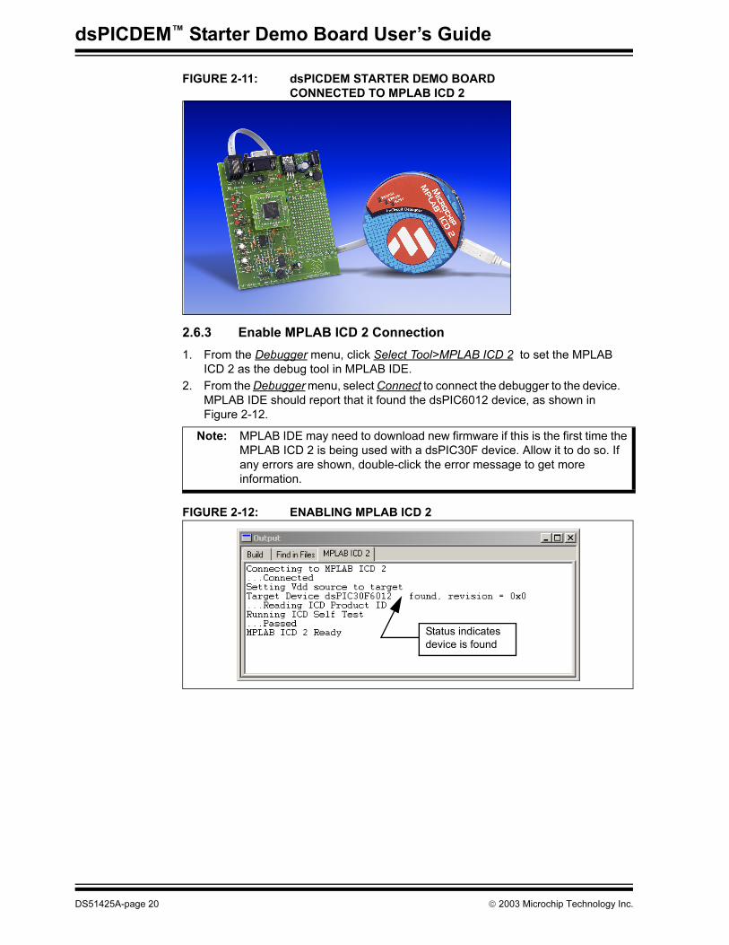
1. Use the Configure>Configuration Bits menu to display the configuration settings.
2. Set up the configuration bits, as shown in Figure 2-10.
The settings that will most likely need to change are:
FIGURE 2-10: CONFIGURATION SETTINGS
2.6.2 Connect the MPLAB ICD 2 In-Circuit Debugger
1. Connect the MPLAB ICD 2 to the PC with the USB cable (see Figure 2-11).
2. Connect the MPLAB ICD 2 to the dsPICDEM Starter Demo Board with the short RJ-11 (telephone) cable.
3. Apply power to the board.
Note: Before proceeding, make sure that the USB driver for the MPLAB ICD 2 has been installed on the PC (see the MPLAB ICD 2 User’s Guide (DS51331) for more details regarding the installation of the MPLAB ICD 2).
Clock Selection XTL
Enable WDT Disabled
Background Debug Enabled
2003 Microchip Technology Inc. DS51425A-page 19
dsPICDEM™ Starter Demo Board User’s Guide
FIGURE 2-11: dsPICDEM STARTER DEMO BOARD
CONNECTED TO MPLAB ICD 2
2.6.3 Enable MPLAB ICD 2 Connection
1. From the Debugger menu, click Select Tool>MPLAB ICD 2 to set the MPLAB ICD 2 as the debug tool in MPLAB IDE.
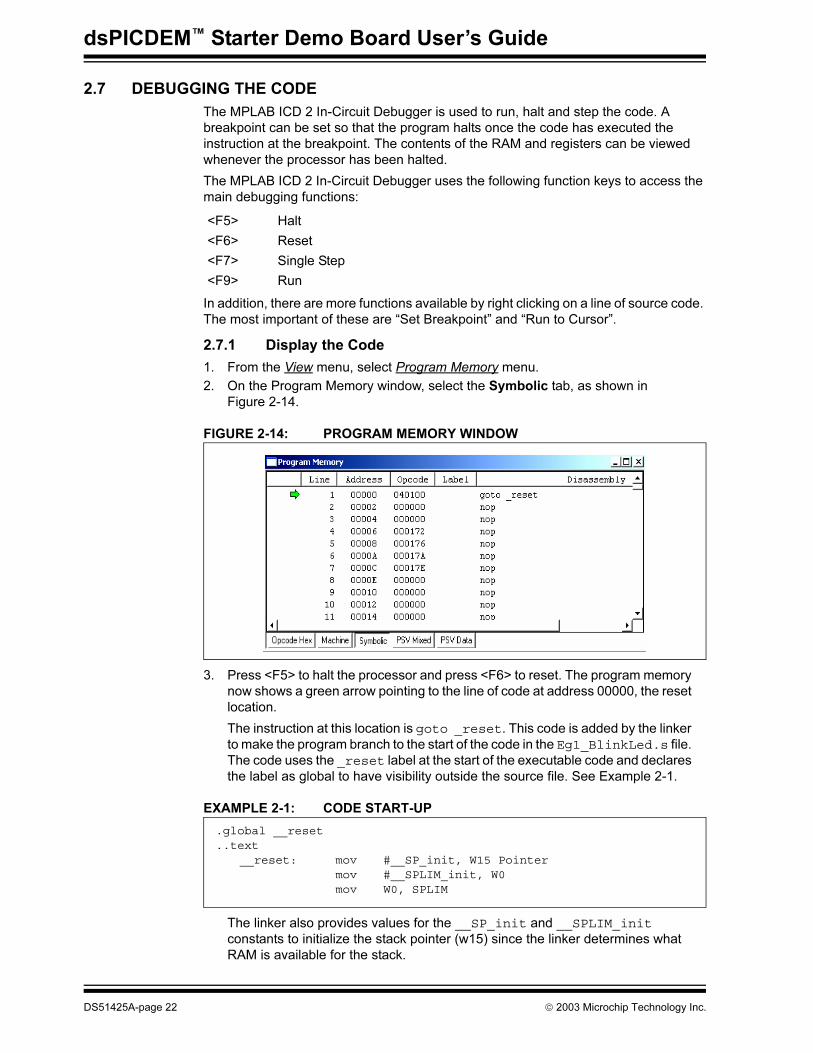
2. From the Debugger menu, select Connect to connect the debugger to the device. MPLAB IDE should report that it found the dsPIC6012 device, as shown in Figure 2-12.
FIGURE 2-12: ENABLING MPLAB ICD 2
Note: MPLAB IDE may need to download new firmware if this is the first time the MPLAB ICD 2 is being used with a dsPIC30F device. Allow it to do so. If any errors are shown, double-click the error message to get more information.
Status indicates
device is found
DS51425A-page 20 2003 Microchip Technology Inc.

Tutorial
2.6.4 Program the dsPIC6012 Device
1. From the Debugger menu, select Program to program the part. The output window (Figure 2-13) displays the program steps as they occur.
2. Observe the results of the programming. When “MPLAB ICD 2 Ready” displays, the device is programmed and ready to run.
FIGURE 2-13: PROGRAMMING THE dsPIC DEVICE
3. Use the Debugger>Run menu to run the code. LED1 should start blinking when S1 is pressed.
2003 Microchip Technology Inc. DS51425A-page 21
dsPICDEM™ Starter Demo Board User’s Guide
2.7 DEBUGGING THE CODE
The MPLAB ICD 2 In-Circuit Debugger is used to run, halt and step the code. A breakpoint can be set so that the program halts once the code has executed the instruction at the breakpoint. The contents of the RAM and registers can be viewed whenever the processor has been halted.
The MPLAB ICD 2 In-Circuit Debugger uses the following function keys to access the main debugging functions:
In addition, there are more functions available by right clicking on a line of source code. The most important of these are “Set Breakpoint” and “Run to Cursor”.
2.7.1 Display the Code
1. From the View menu, select Program Memory menu.
2. On the Program Memory window, select the Symbolic tab, as shown in Figure 2-14.
FIGURE 2-14: PROGRAM MEMORY WINDOW
3. Press <F5> to halt the processor and press <F6> to reset. The program memory now shows a green arrow pointing to the line of code at address 00000, the reset location.
The instruction at this location is goto _reset. This code is added by the linker to make the program branch to the start of the code in the Eg1_BlinkLed.s file. The code uses the _reset label at the start of the executable code and declares the label as global to have visibility outside the source file. See Example 2-1.
EXAMPLE 2-1: CODE START-UP
The linker also provides values for the __SP_init and __SPLIM_init constants to initialize the stack pointer (w15) since the linker determines what RAM is available for the stack.
<F5> Halt
<F6> Reset
<F7> Single Step
<F9> Run
.global __reset
..text__reset: mov #__SP_init, W15 Pointer
mov #__SPLIM_init, W0mov W0, SPLIM
DS51425A-page 22 2003 Microchip Technology Inc.
Tutorial
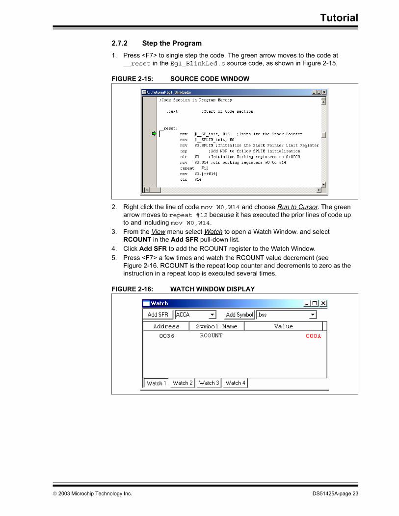
2.7.2 Step the Program
1. Press <F7> to single step the code. The green arrow moves to the code at __reset in the Eg1_BlinkLed.s source code, as shown in Figure 2-15.
FIGURE 2-15: SOURCE CODE WINDOW
2. Right click the line of code mov W0,W14 and choose Run to Cursor. The green arrow moves to repeat #12 because it has executed the prior lines of code up to and including mov W0,W14.
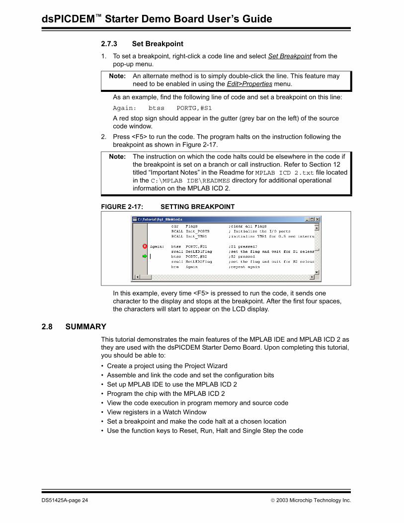
3. From the View menu select Watch to open a Watch Window. and select RCOUNT in the Add SFR pull-down list.
4. Click Add SFR to add the RCOUNT register to the Watch Window.
5. Press <F7> a few times and watch the RCOUNT value decrement (see Figure 2-16. RCOUNT is the repeat loop counter and decrements to zero as the instruction in a repeat loop is executed several times.
FIGURE 2-16: WATCH WINDOW DISPLAY
2003 Microchip Technology Inc. DS51425A-page 23
dsPICDEM™ Starter Demo Board User’s Guide
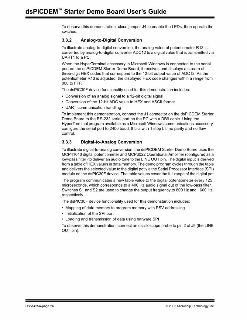
2.7.3 Set Breakpoint
1. To set a breakpoint, right-click a code line and select Set Breakpoint from the pop-up menu.
As an example, find the following line of code and set a breakpoint on this line:
Again: btss PORTG,#S1
A red stop sign should appear in the gutter (grey bar on the left) of the source code window.
2. Press <F5> to run the code. The program halts on the instruction following the breakpoint as shown in Figure 2-17.
FIGURE 2-17: SETTING BREAKPOINT
In this example, every time <F5> is pressed to run the code, it sends one character to the display and stops at the breakpoint. After the first four spaces, the characters will start to appear on the LCD display.
2.8 SUMMARY
This tutorial demonstrates the main features of the MPLAB IDE and MPLAB ICD 2 as they are used with the dsPICDEM Starter Demo Board. Upon completing this tutorial, you should be able to:
• Create a project using the Project Wizard
• Assemble and link the code and set the configuration bits
• Set up MPLAB IDE to use the MPLAB ICD 2
• Program the chip with the MPLAB ICD 2
• View the code execution in program memory and source code
• View registers in a Watch Window
• Set a breakpoint and make the code halt at a chosen location
• Use the function keys to Reset, Run, Halt and Single Step the code
Note: An alternate method is to simply double-click the line. This feature may need to be enabled in using the Edit>Properties menu.
Note: The instruction on which the code halts could be elsewhere in the code if the breakpoint is set on a branch or call instruction. Refer to Section 12 titled “Important Notes” in the Readme for MPLAB ICD 2.txt file located in the C:\MPLAB IDE\READMES directory for additional operational information on the MPLAB ICD 2.
DS51425A-page 24 2003 Microchip Technology Inc.

dsPICDEM™ STARTER
DEMO BOARD USER’S GUIDEChapter 3. Demonstration Program Operation
3.1 INTRODUCTION
The dsPICDEM Starter Demo Board is shipped with example applications programmed into the dsPIC device. These examples exercise several of the dsPIC peripherals such as the 12-bit ADC and UART interfaces. This chapter provides an overview of the demonstration code. Detailed information on the dsPICDEM Starter Demo Board hardware is presented in Chapter 4. “dsPICDEM™ Development Hardware” and Appendix A. “Drawings and Schematics”.
3.2 HIGHLIGHTS
Items discussed in this chapter are:
• Demonstration Program Summary
• Demonstration Code Operation
• Manufacture Test Code Module Summary
3.3 DEMONSTRATION PROGRAM SUMMARY
The preprogrammed demonstation program includes two functionally separate code modules:
• Demonstration code module
• Board self-test code module
These two code modules have been combined into one composite program and coded into the device. The board self test code module has been included on the CD as a library archive only and is briefly discussed at the end of this section. The following sections present the operation of each module.
When power is applied to the dsPICDEM Starter Demo Board the dsPIC device begins executing the demonstration program, which consists of three distinct functional tasks:
• Interrupt processing
• Analog-to-digital conversion
• Digital-to-analog conversion
3.3.1 Interrupt Processing
To illustrate interrupt processing, the demonstration program uses switches S1 and S2 as interrupt devices to drive LEDs RD4 and RD5 (output devices). When switch S1 is pressed (to represent an interrupt), LED RD4 blinks at a 1 Hz rate (once per second) until switch S1 is pressed again. Similarly, when switch S2 is pressed, LED RD5 blinks until switch S2 is pressed again.
The dsPIC30F device functionality used in this demonstration program includes:
• Setting up I/O ports
• Setting up timer interrupts
• Handling interrupts
2003 Microchip Technology Inc. DS51425A-page 25
dsPICDEM™ Starter Demo Board User’s Guide
To observe this demonstration, close jumper J4 to enable the LEDs, then operate the swiches.
3.3.2 Analog-to-Digital Conversion
To illustrate analog-to-digital conversion, the analog value of potentiometer R13 is converted by analog-to-digital converter ADC12 to a digital value that is transmitted via UART1 to a PC.
When the HyperTerminal accessory in Microsoft Windows is connected to the serial port on the dsPICDEM Starter Demo Board, it receives and displays a stream of three-digit HEX codes that correspond to the 12-bit output value of ADC12. As the potentiometer R13 is adjusted, the displayed HEX code changes within a range from 000 to FFF.
The dsPIC30F device functionality used for this demonstration includes:
• Conversion of an analog signal to a 12-bit digital signal
• Conversion of the 12-bit ADC value to HEX and ASCII format
• UART communication handling
To implement this demonstration, connect the J1 connector on the dsPICDEM Starter Demo Board to the RS-232 serial port on the PC with a DB9 cable. Using the HyperTerminal program available as a Microsoft Windows communications accessory, configure the serial port to 2400 baud, 8 bits with 1 stop bit, no parity and no flow control.
3.3.3 Digital-to-Analog Conversion
To illustrate digital-to-analog conversion, the dsPICDEM Starter Demo Board uses the MCP41010 digital potentiometer and MCP6022 Operational Amplifier (configured as a low-pass filter) to deliver an audio tone to the LINE OUT pin. The digital input is derived from a table of HEX values in data memory. The demo program cycles through the table and delivers the selected value to the digital pot via the Serial Processor Interface (SPI) module on the dsPIC30F device. The table values cover the full range of the digital pot.
The program communicates a new table value to the digital potentiometer every 125 microseconds, which corresponds to a 400 Hz audio signal out of the low-pass filter. Switches S1 and S2 are used to change the output frequency to 800 Hz and 1600 Hz, respectively.
The dsPIC30F device functionality used for this demonstartion includes:
• Mapping of data memory to program memory with PSV addressing
• Initialization of the SPI port
• Loading and transmission of data using harware SPI
To observe this demonstration, connect an oscilloscope probe to pin 2 of J9 (the LINE OUT pin).
DS51425A-page 26 2003 Microchip Technology Inc.
Demonstration Program Operation
3.4 DEMONSTRATION CODE OPERATION
The following sections describe in more detail how the demonstration programs interact with and take advantage of key dsPIC30F MCU, DSP and peripheral features. Full details on the peripheral functionality and associated tasks are presented later in this document.
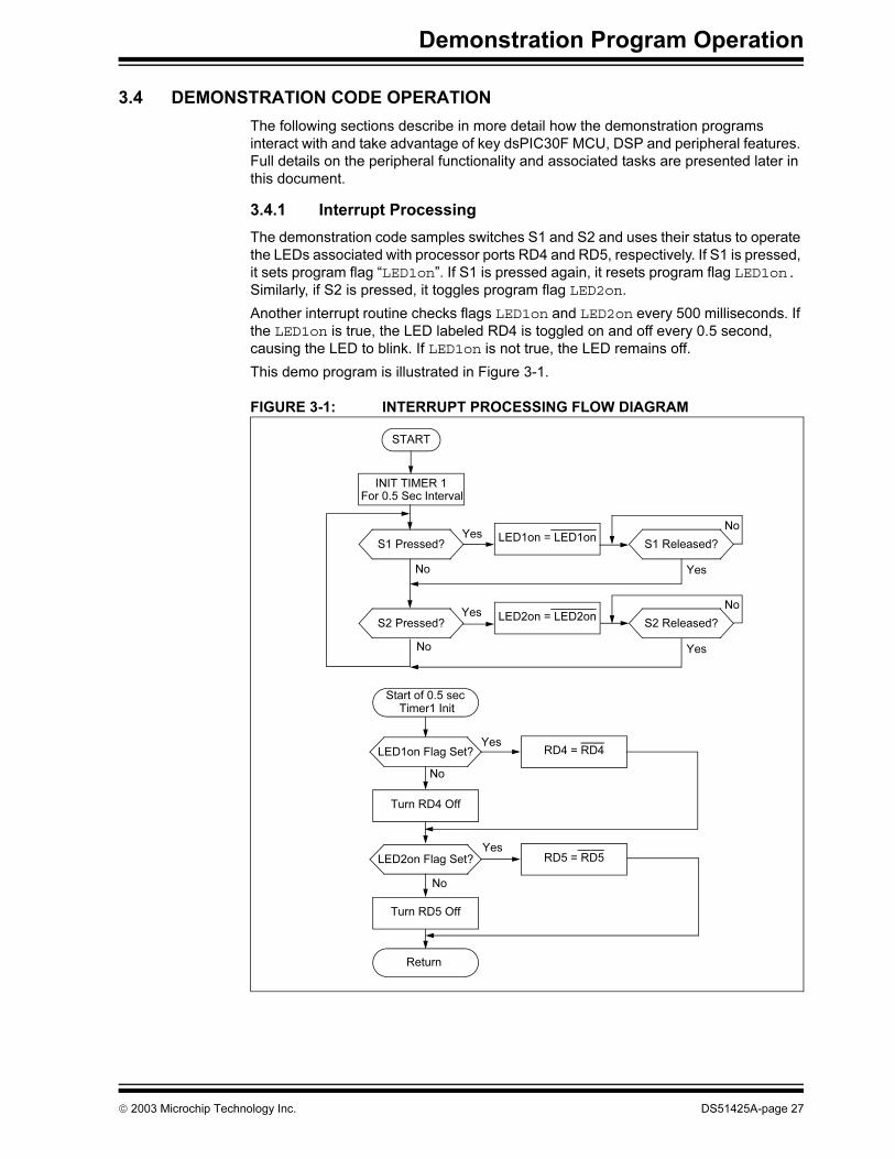
3.4.1 Interrupt Processing
The demonstration code samples switches S1 and S2 and uses their status to operate the LEDs associated with processor ports RD4 and RD5, respectively. If S1 is pressed, it sets program flag “LED1on”. If S1 is pressed again, it resets program flag LED1on. Similarly, if S2 is pressed, it toggles program flag LED2on.
Another interrupt routine checks flags LED1on and LED2on every 500 milliseconds. If the LED1on is true, the LED labeled RD4 is toggled on and off every 0.5 second, causing the LED to blink. If LED1on is not true, the LED remains off.
This demo program is illustrated in Figure 3-1.
FIGURE 3-1: INTERRUPT PROCESSING FLOW DIAGRAM
START
INIT TIMER 1
LED1on = LED1onS1 Pressed?
S2 Pressed?LED2on = LED2on
S1 Released?
S2 Released?
Yes
No
Yes
Yes
Yes
YesNo
No
No
Start of 0.5 sec Timer1 Init
LED1on Flag Set? RD4 = RD4
Turn RD4 Off
LED2on Flag Set? RD5 = RD5
Turn RD5 Off
Return
No
Yes
No
For 0.5 Sec Interval
2003 Microchip Technology Inc. DS51425A-page 27

dsPICDEM™ Starter Demo Board User’s Guide
3.4.2 Analog-to-Digital Conversion
This program consists of two subroutines which (1) perform the A/D conversion and (2) transmit the converted value over an RS-232 serial connection (see Figure 3-2). The A/D conversion routine samples the analog output of Potentiometer RB2. The transmit routine converts the 12-bit binary value from ADC12 to a three-digit HEX code, converts the HEX code to an ASCII character and loads the ASCII value into the transmission buffer of UART1. UART1 transmits each ASCII character with a CR and LF to delimit each sample as a separate line on the receiving terminal.
FIGURE 3-2: ANALOG-TO-DIGITAL CONVERSION FLOW DIAGRAM
INIT ADC12INIT UART
Start A/D Conversion
Convert HEXDigit 3 to ASCII
ADC Complete?
Buffer Full?Load Digit 3 into Transmit Buffer
START
Delay 10 msec
Convert 12-bit Binary to 3-digit HEX
Convert HEXDigit 2 to ASCII
Buffer Full?Load Digit 2 into Transmit Buffer
Convert HEXDigit 1 to ASCII
Buffer Full?Load Digit 1 into Transmit Buffer
Generate ASCIICR
Buffer Full?Load CR into
Transmit Buffer
Generate ASCII LF
Buffer Full?Load Transmit
Buffer
Yes
No
Yes
Yes
Yes
Yes
Yes
No
No
No
No
No
DS51425A-page 28 2003 Microchip Technology Inc.
Demonstration Program Operation
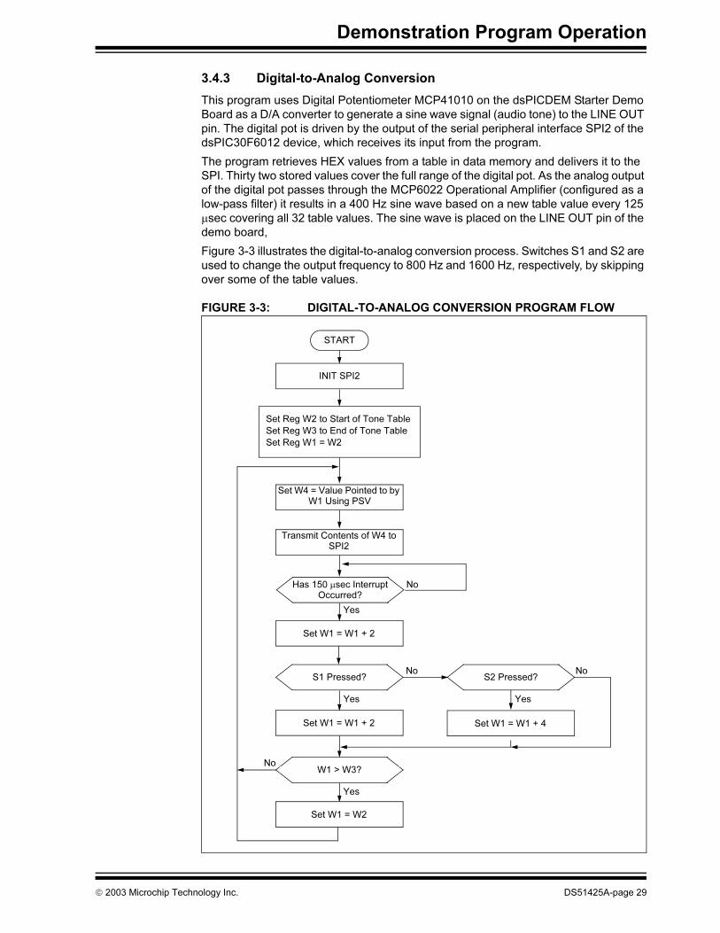
3.4.3 Digital-to-Analog Conversion
This program uses Digital Potentiometer MCP41010 on the dsPICDEM Starter Demo Board as a D/A converter to generate a sine wave signal (audio tone) to the LINE OUT pin. The digital pot is driven by the output of the serial peripheral interface SPI2 of the dsPIC30F6012 device, which receives its input from the program.
The program retrieves HEX values from a table in data memory and delivers it to the SPI. Thirty two stored values cover the full range of the digital pot. As the analog output of the digital pot passes through the MCP6022 Operational Amplifier (configured as a low-pass filter) it results in a 400 Hz sine wave based on a new table value every 125 µsec covering all 32 table values. The sine wave is placed on the LINE OUT pin of the demo board,
Figure 3-3 illustrates the digital-to-analog conversion process. Switches S1 and S2 are used to change the output frequency to 800 Hz and 1600 Hz, respectively, by skipping over some of the table values.
FIGURE 3-3: DIGITAL-TO-ANALOG CONVERSION PROGRAM FLOW
INIT SPI2
Set W4 = Value Pointed to by W1 Using PSV
START
Transmit Contents of W4 to SPI2
Yes
Set Reg W2 to Start of Tone Table
Set Reg W3 to End of Tone Table
Set Reg W1 = W2
Has 150 µsec Interrupt Occurred?
Set W1 = W1 + 2
S1 Pressed? S2 Pressed?
Set W1 = W1 + 2 Set W1 = W1 + 4
Set W1 = W2
No
No No
Yes Yes
Yes
NoW1 > W3?
2003 Microchip Technology Inc. DS51425A-page 29
dsPICDEM™ Starter Demo Board User’s Guide
3.5 BOARD SELF TEST
The board self test is provided for completeness only. User’s do not need to run this test.
1. Power the board using a 9V DC supply and the barrel power connector.The LED marked D1 turns ON.
If D1 does not light:
- the LED is dead, or
- the regulator is dead, or
- the DC supply is not connected to the AC wall plug
2. Using a DMM set for DCV, check that 5V is available at location marked 5V and GND (near the breadboard area).
3. Connect a shorting plug on the RS-232 connector J1. This shorting plug should have pins 2 and 3 connected to one another.
4. Short pins 2 and 3 on line connector J9 using a 0.1″ jumper.
5. Make sure J4 has a 0.1″ jumper on it.
6. To enter the Self test mode, hold down S1, press and release MCLR, then release S1.
The following four tests should run:
Test Description
UART Test This automatic test transmits 5 characters and receives them through
the serial port. During the test, LED RD4 blinks at a very fast rate
(8 blinks/sec). However this test completes so quickly that in most
instances, no noticeable blink of RD4 will occur.
Keypad Test During this test, LED RD5 blinks very fast. You must respond by pressing
S1 and S2. When you press S1, RD4 lights. When you press S2, RD7
lights. If both key presses are acknowledged by the dsPIC then the test
passed. If you get no response or an incorrect response within 4 seconds
then the test is considered failed. In either case the test automatically
proceeds to the Potentiometer test
Potentiometer Test During this test, the LED RD6 blinks rapidly. You must first respond by
turning Potentiometer R13 fully clockwise (RD4 will light) and then fully
counterclockwise (RD7 will light). Then you must move the potentiometer
wiper to a center position causing RD5 to light up. When this happens,
the test is complete. This test must be completed in 8 seconds or else the
test is considered as failed.
Tone Test This procedure automatically tests the Digital Potentiometer and Analog
Operational Amplifier. A sine wave, generated using the digital pot, is
sent through the Op Amp circuit to the ADC of the dsPIC device. The
sine wave is analyzed to determine if a smooth sine wave has been
generated. If all works well the test passes. If there is a fault in the op
amp or digital pot then this test fails.
DS51425A-page 30 2003 Microchip Technology Inc.
Demonstration Program Operation
If any of these tests fail, then at the end of the Tone test the LED corresponding to the failed test will blink slowly (2 blinks/sec). For example if RD4 blinks it means that the UART test failed. The table below correlates the blinking LED with each test and indicates the possible cause for the failure:
If all tests passed, then none of the LEDs will blink.
Blinking LED Test Failed Reasons for Failure
RD4 UART UART driver chip failed; UART shorting
jumper not connected on J1
RD5 Keypad S1 and S2 not working properly
RD6 Potentiometer Pot R13 faulty
RD7 Digital Pot/Op amp Digital Pot/Op Amp failed
2003 Microchip Technology Inc. DS51425A-page 31
dsPICDEM™ Starter Demo Board User’s Guide
NOTES:
DS51425A-page 32 2003 Microchip Technology Inc.

dsPICDEM™ STARTER
DEMO BOARD USER’S GUIDEChapter 4. dsPICDEM™ Development Hardware
4.1 dsPICDEM™ STARTER DEMO BOARD HARDWARE OVERVIEW
This chapter describes the dsPICDEM Starter Demo Board hardware. The dsPICDEM Starter Demo Board features the hardware elements shown in Figure 4-1 and identified in Table 4-1
FIGURE 4-1: dsPICDEM™ STARTER DEMO BOARD
TABLE 4-1: dsPICDEM™ STARTER DEMO BOARD HARDWARE ELEMENTS
No. Hardware Element No. Hardware Element
1 Power On Indicator (Section 4.1.10) 9 Reset Switch (Section 4.1.12)
2 Power Supply (Section 4.1.9) 10 Digital Potentiometer (Section 4.1.5)
3 Sample Device (Section 4.1.14) 11 Pushbutton Switches (Section 4.1.3)
4 Oscillator (Section 4.1.11) 12 LEDs (Section 4.1.4)
5 Prototyping Area (Section 4.1.13) 13 Emulation Header (Section 4.1.8)
6 Low-Pass Filter (Section 4.1.6) 14 ICD 2 Connector (Section 4.1.7)
7 Analog Potentiometer (Section 4.1.2) 15 RS-232 Serial Port (Section 4.1.1)
8 LINE Connector (Section 4.1.15)
1
2
3
4
5
6
7
1514
13
12
11
10
9
8
2003 Microchip Technology Inc. DS51425A-page 33

dsPICDEM™ Starter Demo Board User’s Guide
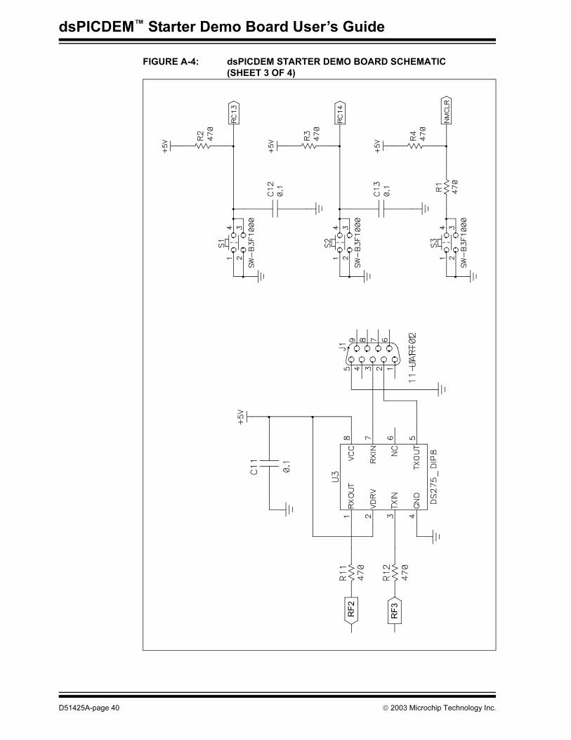
4.1.1 RS-232 Serial Port
The dsPICDEM Starter Demo Board provides one RS-232 serial communication channel. The serial communication channel, labeled J1, is configured as an RS-232 communication channel. The dsPIC UART channel 1 U1RX and U1TX pins are connected to an RS-232 level shifting IC, U3. The serial port is configured as DCE, and can be connected to a PC using a straight through cable.
4.1.2 Analog Potentiometer
One 10 kΩ potentiometer is connected to analog channels AN4, AN5 and AN6. The voltage output range for the potentiometer is 0-5 VDC. The voltage source is provided by the SV regulator on the development board.
4.1.3 Pushbutton Switches
Two switches, S1 and S2 are connected to port pin RC13 and RC14, respectively on the dsPIC device. The signal lines are normally pulled up to +5 VDC through 10 kΩ resistors. Pressing the switch shorts the line to ground. Port pins RC13 and RC14 are configured as input pins.
4.1.4 LEDs
Four red LEDs are connected to port pins RD4 to RD7, respectively on the dsPIC device. These LEDs are labeled RD4 through RD7 on the dsPICDEM Starter Demo Board to correspond to the port pins. The LED anodes are tied to VDD through a 470 ohm resister. The cathodes are shorted and connected to GND by Jumper J4.
4.1.5 Digital Potentiometer
A single channel digital potentiometer, MCP41010 is provided on the development board. The digital potentiometer is controlled by the dsPIC SPI2 communication channel. The output of the digital potentiometer is applied to a 2nd-order, low-pass filter, with a cutoff frequency of approximately 4 kHz. The output of the LP filter is connected to the LINE OUT pin of J9.
4.1.6 Low-Pass Filter
A Microchip MCP6022 Operational Amplifier. The output is configured as a 2nd-order, low-pass filter for speech or voice input filtering. The input to the filter is at the LINE IN pin of J9.
4.1.7 ICD 2 Connector
By way of the modular connector ICD, the MPLAB ICD 2 can be connected for low cost programming and debugging of the dsPIC device.
4.1.8 Emulation Header
Header P1 provides for a connection to the ICE 4K In-Circuit Emulator. The emulation header also supports the processor adaptor boards. The processor adaptor boards enable quick change out of the 64-pin TQFP device.
4.1.9 Power Supply
The dsPICDEM™ Starter Demo Board is powered by a +9V, AC/DC wall adapter. A +5 VDC regulator (VDD and AVDD) provides power to the respective processor pins and prototyping area. A ground trace connects all VSS points.
DS51425A-page 34 2003 Microchip Technology Inc.
dsPICDEM™ Development Hardware
4.1.10 Power On Indicator
A red LED is connected to the input of the regulators to indicate the presence of power.
4.1.11 Oscillator
A crystal oscillator (4.00 MHz) is supplied.
4.1.12 Reset Switch
The MCLR Reset switch (S3) connected to the processor MCLR pin provides a hard reset to the dsPIC device.
4.1.13 Prototyping Area
A prototyping area and associated header is provided which enables additional ICs and attachment boards to be added.
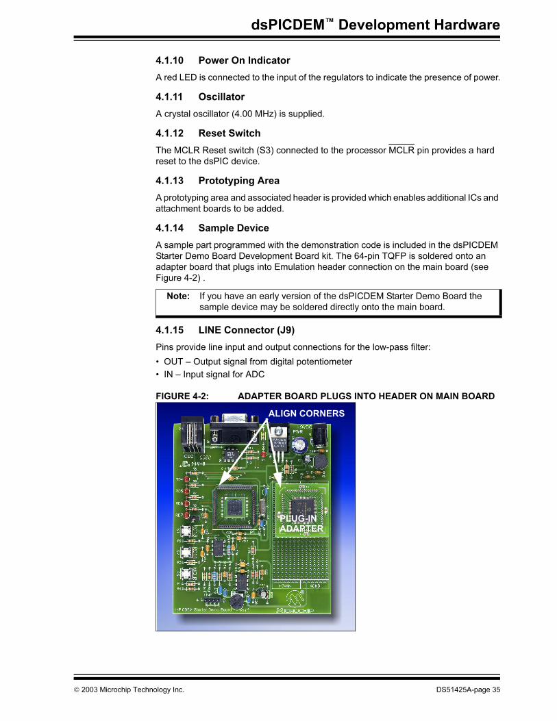
4.1.14 Sample Device
A sample part programmed with the demonstration code is included in the dsPICDEM Starter Demo Board Development Board kit. The 64-pin TQFP is soldered onto an adapter board that plugs into Emulation header connection on the main board (see Figure 4-2) .
4.1.15 LINE Connector (J9)
Pins provide line input and output connections for the low-pass filter:
• OUT – Output signal from digital potentiometer
• IN – Input signal for ADC
FIGURE 4-2: ADAPTER BOARD PLUGS INTO HEADER ON MAIN BOARD
Note: If you have an early version of the dsPICDEM Starter Demo Board the sample device may be soldered directly onto the main board.
PLUG-INADAPTER
ALIGN CORNERS
2003 Microchip Technology Inc. DS51425A-page 35

dsPICDEM™ Starter Demo Board User’s Guide
NOTES:
DS51425A-page 36 2003 Microchip Technology Inc.
dsPICDEM™ STARTER
DEMO BOARD USER’S GUIDEAppendix A. Drawings and Schematics
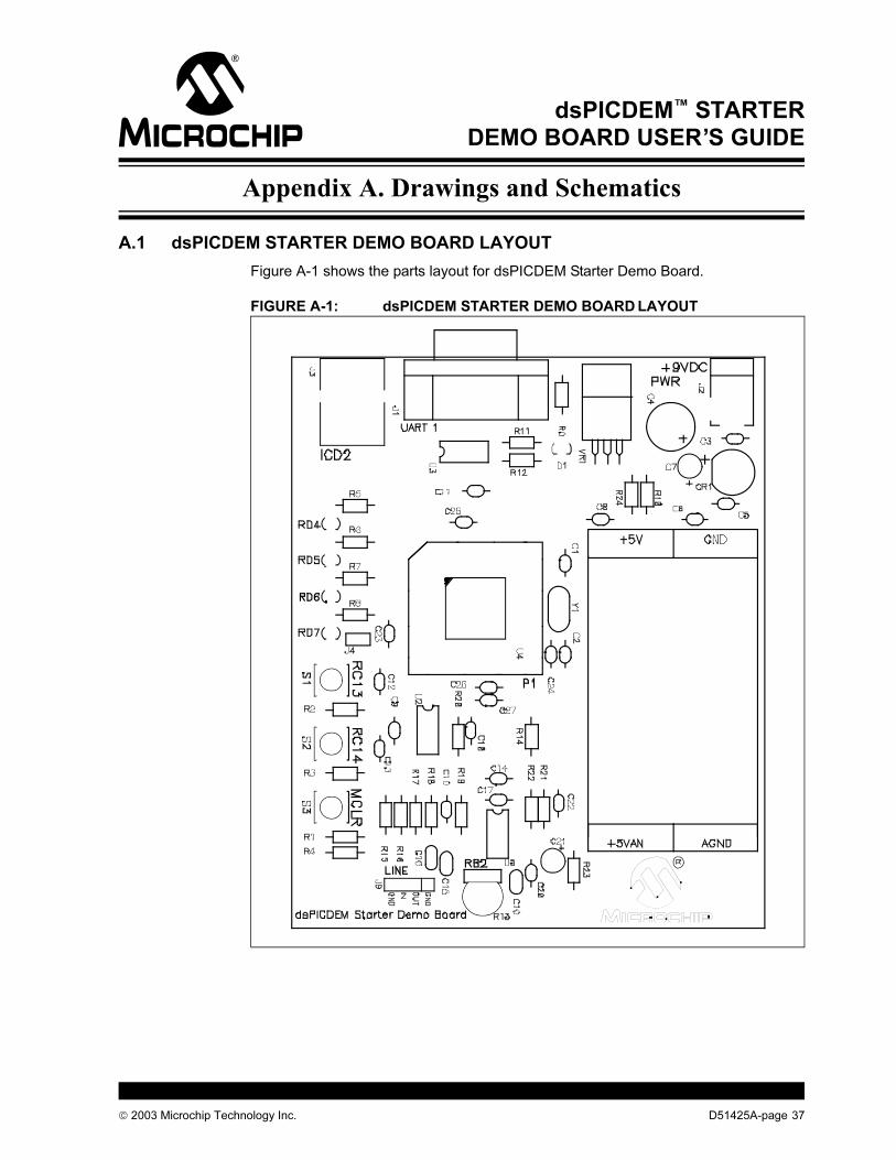
A.1 dsPICDEM STARTER DEMO BOARD LAYOUT
Figure A-1 shows the parts layout for dsPICDEM Starter Demo Board.
FIGURE A-1: dsPICDEM STARTER DEMO BOARD LAYOUT
2003 Microchip Technology Inc. D51425A-page 37
dsPICDEM™ Starter Demo Board User’s Guide
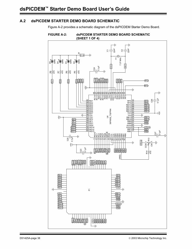
A.2 dsPICDEM STARTER DEMO BOARD SCHEMATIC
Figure A-2 provides a schematic diagram of the dsPICDEM Starter Demo Board.
FIGURE A-2: dsPICDEM STARTER DEMO BOARD SCHEMATIC
(SHEET 1 OF 4)
RF
3
RF5
RF4
RB15
RB14
RB13
RB12
+5V
RB11
RB10
RB9
RB8
+5VAN
RB7
RB6
+5V
RB
5R
B4
RB
3R
B2
RB
1R
B0
RG
9NMCLR
RG
8R
G7
RG
6R
C2
RC
1R
G15
+5V
RF0
RF1
RG1
RG0
RG14
RG12
RG13
P1
RD1
RD2
RD3
RD4
RD5
RD6
RD7
RC
14
RC
13
RD
0R
D11
RD
10
RD
9R
D8
OS
C2
OS
C1
+5V
RG
2R
G3
RF
6R
F2
C25
0.1µ
F+
5V
C23
0.1µ
F
RG
15
RG
15
RC
1R
C1
RC
2R
C2
RG
6R
G6
RG
7R
G7
RG
8R
G8
RG
9R
G9
MC
LR
VSS
VDD
RB
5R
B5
RB
4R
B4
RB
3R
B3
RB
2R
B2
RB
1R
B1
RB
0R
B0
(AN
2)
R14
470
1 2 3 4 5 6 7 8 910
11
12
13
14 15
16
+5VAN R
13
12
3
CC
W
CW
30F
6002_T
QF
P64
U4
RD1
RD2
RD3
RD4
RD5
RD6
RD7
49
50
51
52
53
54
55
56
57
58
59
60
61
62
63
64
VSS
VDD
RF0
RF1
RG1
RG0
RG14
RG12
RG13
RF0
RF1
RG1
RG0
RG14
RG12
RG13
RF5 RF532
31
30
29
28
27
26
25
24
23
22
RF4 RF4
RB15 RB15
RB14 RB14
RB13 RB13
RB12 RB12
VDD
VSS
RB11 RB11
21
20
19
18
17
RB10
RB9
RB8
AVSS
AVDD
RB7
RB6
RB10
RB9
RB8
RB7
RB6
+5VAN
C27
0.1µ
F
C26
0.1µ
F+
5V
RF2
RF3+
5V
RD
7
RD
6
RD
5
RD
4R
D3
RD
2R
D1
48
47
46
RC
14
RC
13
RD
0
RC
14
RC
13
RD
0R
D11
RD
10
45
44
43
RD
11
RD
10
RD
9R
D8
VSS
OS
C2
OS
C1
VDD
42
41
39
38
37
40
RD
9R
D8
36
35
34
33
RG
2R
G3
RF
6R
F2
RF
3
RG
2R
G3
RF
6
OSC2
Y1
7.3
7 M
HZ
C1
22PF
C2
22PF
C24
0.1µ
F
J4
D5
D4
D3
D2
GR
N
GR
N
GR
N
GR
N
R8
R7
R6
R5
470
470
470
470
+5V
D51425A-page 38 2003 Microchip Technology Inc.
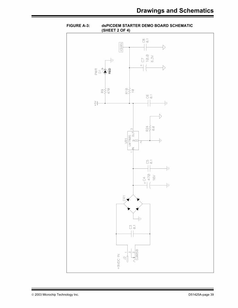
Drawings and Schematics
FIGURE A-3: dsPICDEM STARTER DEMO BOARD SCHEMATIC
(SHEET 2 OF 4)
RED
2003 Microchip Technology Inc. D51425A-page 39
dsPICDEM™ Starter Demo Board User’s Guide
FIGURE A-4: dsPICDEM STARTER DEMO BOARD SCHEMATIC
(SHEET 3 OF 4)
RF2
RF3
D51425A-page 40 2003 Microchip Technology Inc.

Drawings and Schematics
FIGURE A-5: dsPICDEM STARTER DEMO BOARD SCHEMATIC
(SHEET 4 OF 4)
C22
0.0
1µ
f
R21
12K
R20
6.1
K
C19
2200pF
5 6
1 2 3 4
J9
LIN
E
C16
0.0
68µ
F
R15
100K
R17
6.1
KR
16
100K
+5V
U5:B
7
MC
P6022_D
IP8
R18
12K
C15
2200pF
R22
82
C20
0.4
7µ
F
C10
0.1µ
F
C21
10.0µ
FR
23
10K
C18
0.0
1µ
F
C17
0.1µ
F
3 2
48U
5:A 1
MC
P6022_D
IP8
+5V
C9
0.1µ
F
8 7 6 5
VDD
CS
SC
KS
1VSS
U2
MC
P4101_D
IP8
ICD
2
J3
+5V
(EM
UD
)
(EM
UC
)
1 2 3 4 5 6
R19
82
C14
0.4
7µ
F1 2 3 4
odS
odU
odV
kj`io
o_P
o_O
o_N
o_M
E^kPF
ifkb|lrq
ifkb|fk
2003 Microchip Technology Inc. D51425A-page 41

dsPICDEM™ Starter Demo Board User’s Guide
NOTES:
D51425A-page 42 2003 Microchip Technology Inc.

dsPICDEM™ STARTER
DEMO BOARD USER’S GUIDEIndex
A
A/D Conversion Demo Program............................... 28
A/D Conversion Flow Diagram................................. 28
Analog Features......................................................... 8
Analog Pot ............................................................... 34
Assembler Include Path ........................................... 17
B
Board ....................................................................... 33
Board SelfTest ......................................................... 30
Breakpoint ...........................................................22, 24
Build Options............................................................ 16
C
Communication Channel............................................ 8
Configuration Bits..................................................... 19
Connections
MPLAB ICD 2 ..................................................... 8
MPLAB ICE 4000................................................ 8
Customer Notification Service.................................... 5
Customer Support ...................................................... 6
D
D/A Conversion Demo Program............................... 29
Debugging................................................................ 22
Demo Board Layout ................................................. 37
Demo Board Schematic ......................................38–41
Demonstration Program
Analog-to-Digital Conversion .......................26, 28
Digital-to-Analog Conversion .......................26, 29
Interrupt Processing.....................................25, 27
Overview Description .......................................... 9
Summary .......................................................... 25
Development Board Features
Analog................................................................. 8
Device Clocking .................................................. 8
External Stimulus Switches ................................ 8
LED Indicators .................................................... 8
MPLAB ICD 2 Connections ................................ 8
MPLAB ICE4000 Connections............................ 8
Power Supply Circuit .......................................... 8
Prototype Area.................................................... 8
Reset Push Button.............................................. 8
Serial Communication Channels......................... 8
Development Board Power ........................................ 8
Device Clocking ......................................................... 8
Digital Pot................................................................. 34
Documentation
Numbering Conventions ..................................... 2
Updates .............................................................. 2
E
Emulation Header .................................................... 34
F
Flow Diagram
Analog-to-Digital Conversion ............................ 28
Interrupt Processing.......................................... 27
Free Software Foundation.......................................... 4
G
GNU language tools................................................... 4
H
Hardware.................................................................. 33
Analog Potentiometer ....................................... 34
Digital Potentiometer......................................... 34
Emulation Header ............................................. 34
ICD 2 Connector ............................................... 34
LEDs ................................................................. 34
Low-Pass Filter ................................................. 34
Oscillator ........................................................... 35
Power On Indicator ........................................... 35
Power Supply.................................................... 34
Prototyping Area ............................................... 35
Pushbutton Switches ........................................ 34
Reset Switch ..................................................... 35
RS-232 Serial Port ............................................ 34
Sample Devices ................................................ 35
I
ICD 2 Connector ...................................................... 34
Internet Address......................................................... 4
Interrupt Processing Flow Diagram.......................... 27
L
Language Toolsuite.................................................. 13
LEDs ........................................................................ 34
Low-Pass Filter ........................................................ 34
M
Microchip Internet Web Site ....................................... 4
MPLAB IDE ............................................................ 2, 8
MPLAB ICD 2............................................................. 9
MPLAB ICE 4000 ....................................................... 8
MPLAB ICE User’s Guide .......................................... 9
MPLAB IDE User’s Guide .......................................... 4
O
Oscillator .................................................................. 35
2003 Microchip Technology Inc. DS51425A-page 43
dsPICDEM™ Starter Demo Board User’s Guide
P
Power On Indicator .................................................. 35
Power Supply ........................................................... 34
Project ...................................................................... 12
Project Wizard.......................................................... 12
Prototyping Area ...................................................... 35
Pushbutton Switches................................................ 34
R
Recommended Reading............................................. 3
Reference Documents................................................ 9
Reset Switch ............................................................ 35
RS-232 Serial Port ................................................... 34
S
Sample Device ......................................................... 35
Schematics......................................................... 38–41
Serial Communication Channel.................................. 8
W
Warranty Registration................................................. 2
Watch Window ......................................................... 23
Workspace ............................................................... 12
WWW Address........................................................... 4
DS51425A-page 44 2003 Microchip Technology Inc.

Index
NOTES:
2003 Microchip Technology Inc. DS51425A-page 45

dsPICDEM™ Starter Demo Board User’s Guide
NOTES:
DS51425A-page 46 2003 Microchip Technology Inc.

Index
NOTES:
2003 Microchip Technology Inc. DS51425A-page 47
DS51425A-page 48 2003 Microchip Technology Inc.
AMERICAS
Corporate Office2355 West Chandler Blvd.Chandler, AZ 85224-6199Tel: 480-792-7200 Fax: 480-792-7277Technical Support: 480-792-7627Web Address: http://www.microchip.com
Atlanta3780 Mansell Road, Suite 130Alpharetta, GA 30022Tel: 770-640-0034 Fax: 770-640-0307
Boston2 Lan Drive, Suite 120Westford, MA 01886Tel: 978-692-3848 Fax: 978-692-3821
Chicago333 Pierce Road, Suite 180Itasca, IL 60143Tel: 630-285-0071 Fax: 630-285-0075
Dallas4570 Westgrove Drive, Suite 160Addison, TX 75001Tel: 972-818-7423 Fax: 972-818-2924
DetroitTri-Atria Office Building 32255 Northwestern Highway, Suite 190Farmington Hills, MI 48334Tel: 248-538-2250Fax: 248-538-2260
Kokomo2767 S. Albright Road Kokomo, IN 46902Tel: 765-864-8360Fax: 765-864-8387
Los Angeles18201 Von Karman, Suite 1090Irvine, CA 92612Tel: 949-263-1888 Fax: 949-263-1338
Phoenix2355 West Chandler Blvd.Chandler, AZ 85224-6199Tel: 480-792-7966 Fax: 480-792-4338
San Jose2107 North First Street, Suite 590San Jose, CA 95131Tel: 408-436-7950 Fax: 408-436-7955
Toronto6285 Northam Drive, Suite 108Mississauga, Ontario L4V 1X5, CanadaTel: 905-673-0699 Fax: 905-673-6509
ASIA/PACIFIC
AustraliaSuite 22, 41 Rawson StreetEpping 2121, NSWAustraliaTel: 61-2-9868-6733 Fax: 61-2-9868-6755
China - BeijingUnit 915Bei Hai Wan Tai Bldg.No. 6 Chaoyangmen Beidajie Beijing, 100027, No. ChinaTel: 86-10-85282100 Fax: 86-10-85282104
China - ChengduRm. 2401-2402, 24th Floor, Ming Xing Financial TowerNo. 88 TIDU StreetChengdu 610016, ChinaTel: 86-28-86766200 Fax: 86-28-86766599
China - FuzhouUnit 28F, World Trade PlazaNo. 71 Wusi RoadFuzhou 350001, ChinaTel: 86-591-7503506 Fax: 86-591-7503521
China - Hong Kong SARUnit 901-6, Tower 2, Metroplaza223 Hing Fong RoadKwai Fong, N.T., Hong KongTel: 852-2401-1200 Fax: 852-2401-3431
China - ShanghaiRoom 701, Bldg. BFar East International PlazaNo. 317 Xian Xia RoadShanghai, 200051Tel: 86-21-6275-5700 Fax: 86-21-6275-5060
China - ShenzhenRm. 1812, 18/F, Building A, United PlazaNo. 5022 Binhe Road, Futian DistrictShenzhen 518033, ChinaTel: 86-755-82901380 Fax: 86-755-8295-1393
China - ShundeRoom 401, Hongjian BuildingNo. 2 Fengxiangnan Road, Ronggui TownShunde City, Guangdong 528303, ChinaTel: 86-765-8395507 Fax: 86-765-8395571
China - QingdaoRm. B505A, Fullhope Plaza,No. 12 Hong Kong Central Rd.Qingdao 266071, ChinaTel: 86-532-5027355 Fax: 86-532-5027205
IndiaDivyasree Chambers1 Floor, Wing A (A3/A4)No. 11, O’Shaugnessey RoadBangalore, 560 025, IndiaTel: 91-80-2290061 Fax: 91-80-2290062
JapanBenex S-1 6F3-18-20, ShinyokohamaKohoku-Ku, Yokohama-shiKanagawa, 222-0033, JapanTel: 81-45-471- 6166 Fax: 81-45-471-6122
Korea168-1, Youngbo Bldg. 3 FloorSamsung-Dong, Kangnam-KuSeoul, Korea 135-882Tel: 82-2-554-7200 Fax: 82-2-558-5932 or 82-2-558-5934
Singapore200 Middle Road#07-02 Prime CentreSingapore, 188980Tel: 65-6334-8870 Fax: 65-6334-8850
TaiwanKaohsiung Branch30F - 1 No. 8Min Chuan 2nd RoadKaohsiung 806, TaiwanTel: 886-7-536-4818Fax: 886-7-536-4803
TaiwanTaiwan Branch11F-3, No. 207Tung Hua North RoadTaipei, 105, TaiwanTel: 886-2-2717-7175 Fax: 886-2-2545-0139
EUROPEAustriaDurisolstrasse 2A-4600 WelsAustriaTel: 43-7242-2244-399Fax: 43-7242-2244-393
DenmarkRegus Business CentreLautrup hoj 1-3Ballerup DK-2750 DenmarkTel: 45-4420-9895 Fax: 45-4420-9910
FranceParc d’Activite du Moulin de Massy43 Rue du Saule TrapuBatiment A - ler Etage91300 Massy, FranceTel: 33-1-69-53-63-20 Fax: 33-1-69-30-90-79
GermanySteinheilstrasse 10D-85737 Ismaning, GermanyTel: 49-89-627-144-0 Fax: 49-89-627-144-44
ItalyVia Quasimodo, 1220025 Legnano (MI)Milan, Italy Tel: 39-0331-742611 Fax: 39-0331-466781
NetherlandsP. A. De Biesbosch 14NL-5152 SC Drunen, NetherlandsTel: 31-416-690399 Fax: 31-416-690340
United Kingdom505 Eskdale RoadWinnersh TriangleWokingham Berkshire, England RG41 5TUTel: 44-118-921-5869Fax: 44-118-921-5820
07/28/03
WORLDWIDE SALES AND SERVICE