Embed Size (px)
Citation preview
DSP-CIS
Chapter-7: Filter Banks -Preliminaries
Marc MoonenDept. E.E./ESAT-STADIUS, KU Leuven
www.esat.kuleuven.be/stadius/
DSP-CIS / Chapter 7: Filter Banks – Preliminaries / Version 2014-2015 p. 2
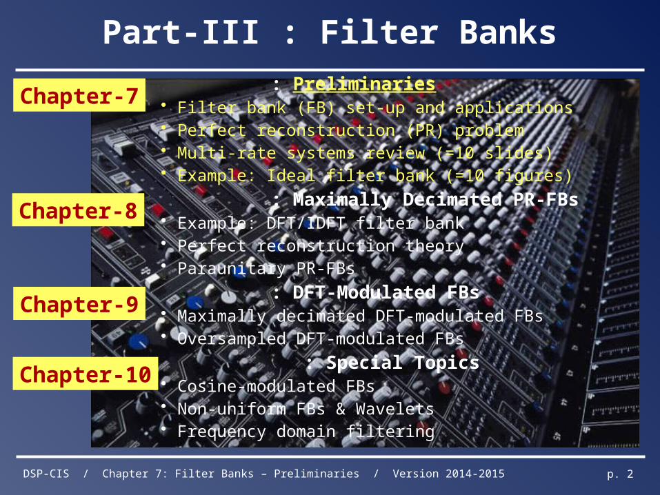
: Preliminaries• Filter bank (FB) set-up and applications • Perfect reconstruction (PR) problem • Multi-rate systems review (=10 slides)• Example: Ideal filter bank (=10 figures)
: Maximally Decimated PR-FBs• Example: DFT/IDFT filter bank• Perfect reconstruction theory• Paraunitary PR-FBs
: DFT-Modulated FBs• Maximally decimated DFT-modulated FBs• Oversampled DFT-modulated FBs
: Special Topics• Cosine-modulated FBs• Non-uniform FBs & Wavelets• Frequency domain filtering
Chapter-7
Chapter-8
Chapter-9
Chapter-10
Part-III : Filter Banks
DSP-CIS / Chapter 7: Filter Banks – Preliminaries / Version 2014-2015 p. 3
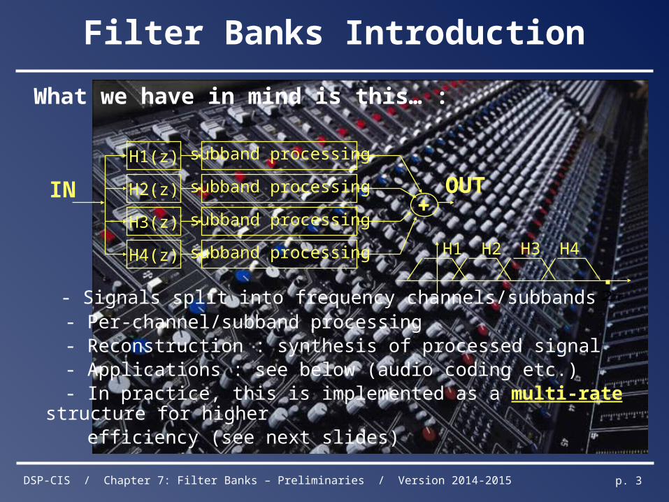
Filter Banks Introduction
What we have in mind is this… :
- Signals split into frequency channels/subbands - Per-channel/subband processing - Reconstruction : synthesis of processed signal - Applications : see below (audio coding etc.) - In practice, this is implemented as a multi-rate structure for higher efficiency (see next slides)
subband processing
subband processing
subband processing
subband processing
H1(z)
H2(z)
H3(z)
H4(z)
IN+
OUT
H1 H4H3H2
2
DSP-CIS / Chapter 7: Filter Banks – Preliminaries / Version 2014-2015 p. 4
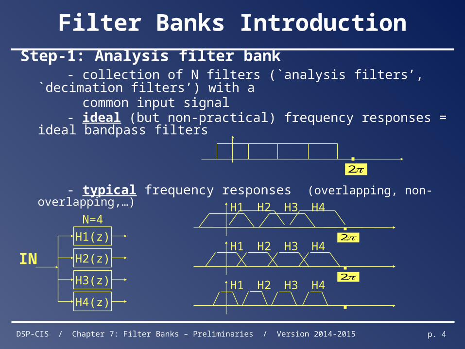
Filter Banks Introduction
Step-1: Analysis filter bank - collection of N filters (`analysis filters’, `decimation filters’) with a common input signal - ideal (but non-practical) frequency responses = ideal bandpass filters
- typical frequency responses (overlapping, non-overlapping,…)
2
H1 H4H3H2
H1 H4H3H2
H1 H4H3H2
2
2
H1(z)
H2(z)
H3(z)
H4(z)
IN
N=4
DSP-CIS / Chapter 7: Filter Banks – Preliminaries / Version 2014-2015 p. 5
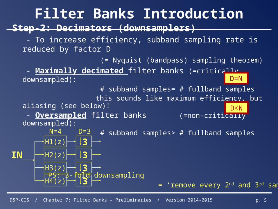
Filter Banks Introduction
Step-2: Decimators (downsamplers) - To increase efficiency, subband sampling rate is reduced by factor D
(= Nyquist (bandpass) sampling theorem)
- Maximally decimated filter banks (=critically downsampled):
# subband samples= # fullband samples this sounds like maximum efficiency, but aliasing (see below)!
- Oversampled filter banks (=non-critically downsampled):
# subband samples> # fullband samples
D=N
D<N
H1(z)
H2(z)
H3(z)
3
3
3
3H4(z)
IN
N=4 D=3
PS: 3-fold downsampling
= ‘remove every 2nd and 3rd sample’ (see p.32)
DSP-CIS / Chapter 7: Filter Banks – Preliminaries / Version 2014-2015 p. 6
Filter Banks Introduction
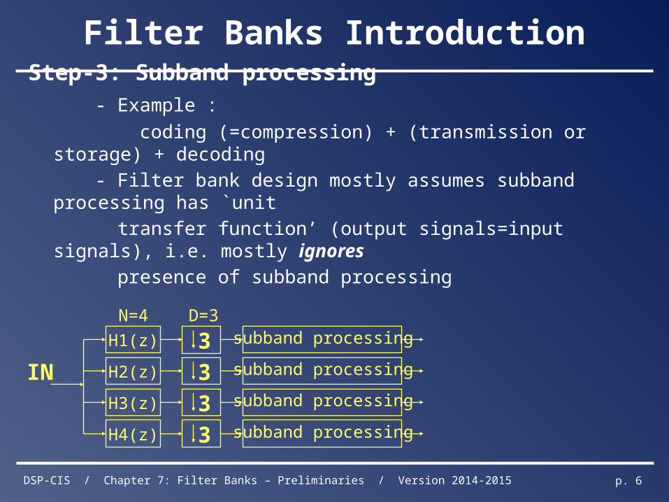
Step-3: Subband processing
- Example :
coding (=compression) + (transmission or storage) + decoding
- Filter bank design mostly assumes subband processing has `unit
transfer function’ (output signals=input signals), i.e. mostly ignores
presence of subband processing
subband processingH1(z)
subband processingH2(z)
subband processingH3(z)
3
3
3
3 subband processingH4(z)
IN
N=4 D=3
DSP-CIS / Chapter 7: Filter Banks – Preliminaries / Version 2014-2015 p. 7
Filter Banks Introduction
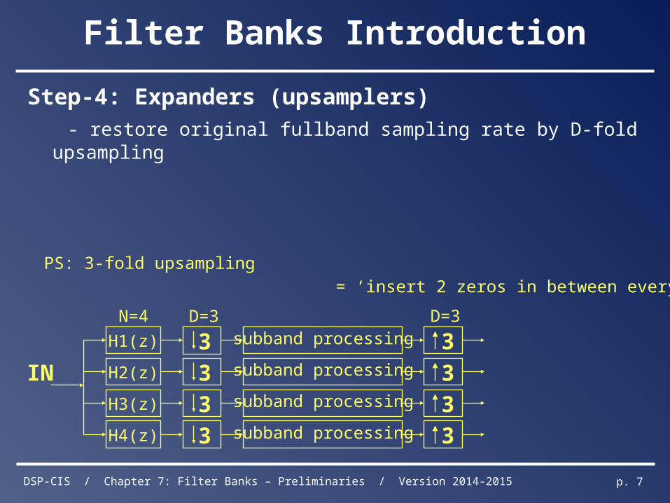
Step-4: Expanders (upsamplers)
- restore original fullband sampling rate by D-fold upsampling
subband processing 3H1(z)
subband processing 3H2(z)
subband processing 3H3(z)
3
3
3
3 subband processing 3H4(z)
IN
N=4 D=3 D=3
PS: 3-fold upsampling
= ‘insert 2 zeros in between every two samples’ (see p.30)
DSP-CIS / Chapter 7: Filter Banks – Preliminaries / Version 2014-2015 p. 8
Filter Banks Introduction
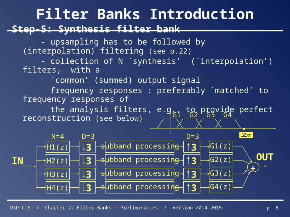
Step-5: Synthesis filter bank - upsampling has to be followed by (interpolation) filtering (see p.22)
- collection of N `synthesis’ (`interpolation’) filters, with a `common’ (summed) output signal - frequency responses : preferably `matched’ to frequency responses of the analysis filters, e.g., to provide perfect reconstruction (see below)
G1(z)
G2(z)
G3(z)
G4(z)
+OUT
subband processing 3H1(z)
subband processing 3H2(z)
subband processing 3H3(z)
3
3
3
3 subband processing 3H4(z)
IN
N=4 D=3 D=3
G1 G4G3G2
2
DSP-CIS / Chapter 7: Filter Banks – Preliminaries / Version 2014-2015 p. 9
Aliasing versus Perfect Reconstruction
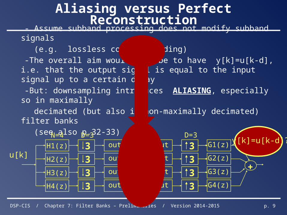
- Assume subband processing does not modify subband signals
(e.g. lossless coding/decoding)
-The overall aim would then be to have y[k]=u[k-d], i.e. that the output signal is equal to the input signal up to a certain delay
-But: downsampling introduces ALIASING, especially so in maximally
decimated (but also in non-maximally decimated) filter banks
(see also p.32-33)
G1(z)
G2(z)
G3(z)
G4(z)
+
output = input 3H1(z)
output = input 3H2(z)
output = input 3H3(z)
3
3
3
3 output = input 3H4(z)
N=4 D=3 D=3
u[k]
y[k]=u[k-d]?
DSP-CIS / Chapter 7: Filter Banks – Preliminaries / Version 2014-2015 p. 10
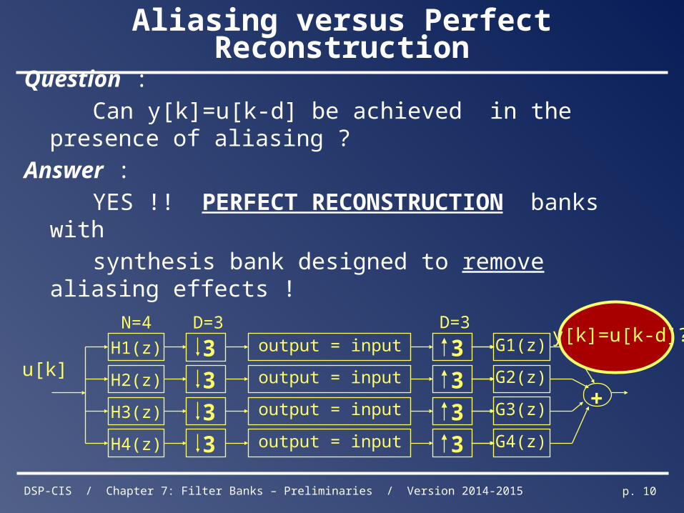
Aliasing versus Perfect Reconstruction
Question :
Can y[k]=u[k-d] be achieved in the presence of aliasing ?
Answer :
YES !! PERFECT RECONSTRUCTION banks with
synthesis bank designed to remove aliasing effects !
G1(z)
G2(z)
G3(z)
G4(z)
+
output = input 3H1(z)
output = input 3H2(z)
output = input 3H3(z)
3
3
3
3 output = input 3H4(z)
N=4 D=3 D=3
u[k]
y[k]=u[k-d]?
DSP-CIS / Chapter 7: Filter Banks – Preliminaries / Version 2014-2015 p. 11
Filter Banks Applications
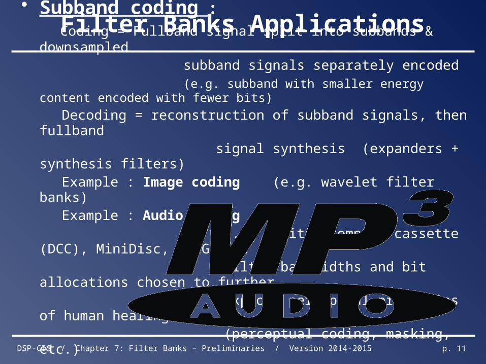
• Subband coding : Coding = Fullband signal split into subbands & downsampled subband signals separately encoded (e.g. subband with smaller energy content encoded with fewer bits)
Decoding = reconstruction of subband signals, then fullband signal synthesis (expanders + synthesis filters) Example : Image coding (e.g. wavelet filter banks) Example : Audio coding e.g. digital compact cassette (DCC), MiniDisc, MPEG, ... Filter bandwidths and bit allocations chosen to further exploit perceptual properties of human hearing (perceptual coding, masking, etc.)
DSP-CIS / Chapter 7: Filter Banks – Preliminaries / Version 2014-2015 p. 12
Filter Banks Applications
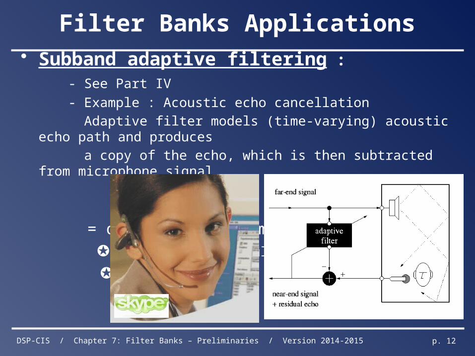
• Subband adaptive filtering :
- See Part IV
- Example : Acoustic echo cancellation
Adaptive filter models (time-varying) acoustic echo path and produces
a copy of the echo, which is then subtracted from microphone signal.
= difficult problem !
✪ long acoustic impulse responses
✪ time-varying
DSP-CIS / Chapter 7: Filter Banks – Preliminaries / Version 2014-2015 p. 13
Filter Banks Applications
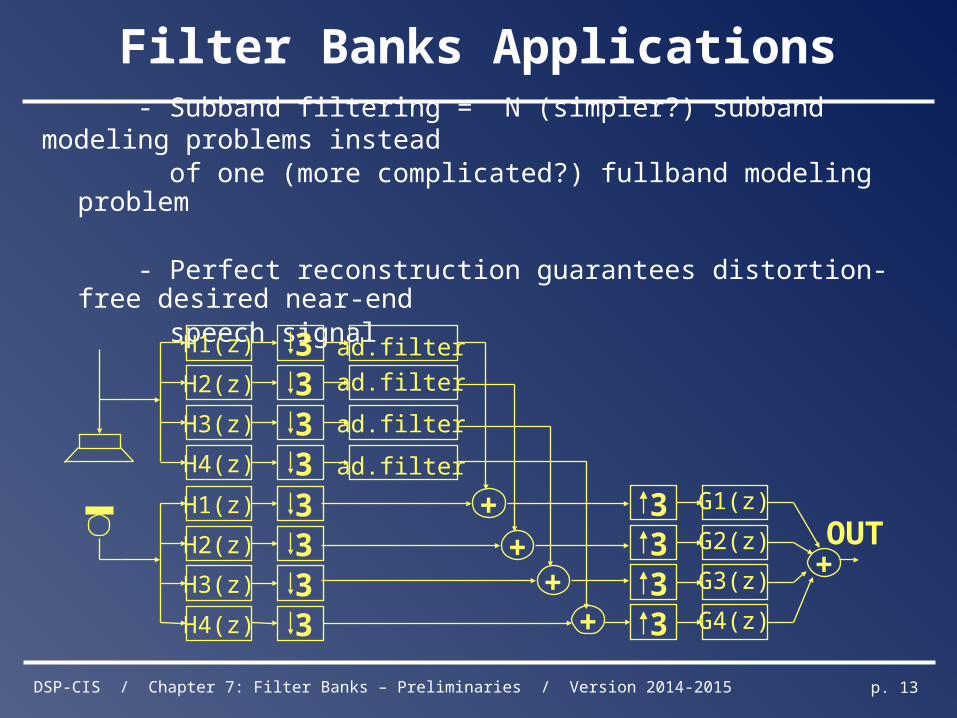
- Subband filtering = N (simpler?) subband modeling problems instead of one (more complicated?) fullband modeling problem
- Perfect reconstruction guarantees distortion-free desired near-end speech signal
3H1(z)
3H2(z)
3H3(z)
3H4(z)
3H1(z)
3H2(z)
3H3(z)
3H4(z) ++
++ 3 G1(z)
3 G2(z)
3 G3(z)
3 G4(z)
OUT+
ad.filter
ad.filter
ad.filter
ad.filter
DSP-CIS / Chapter 7: Filter Banks – Preliminaries / Version 2014-2015 p. 14
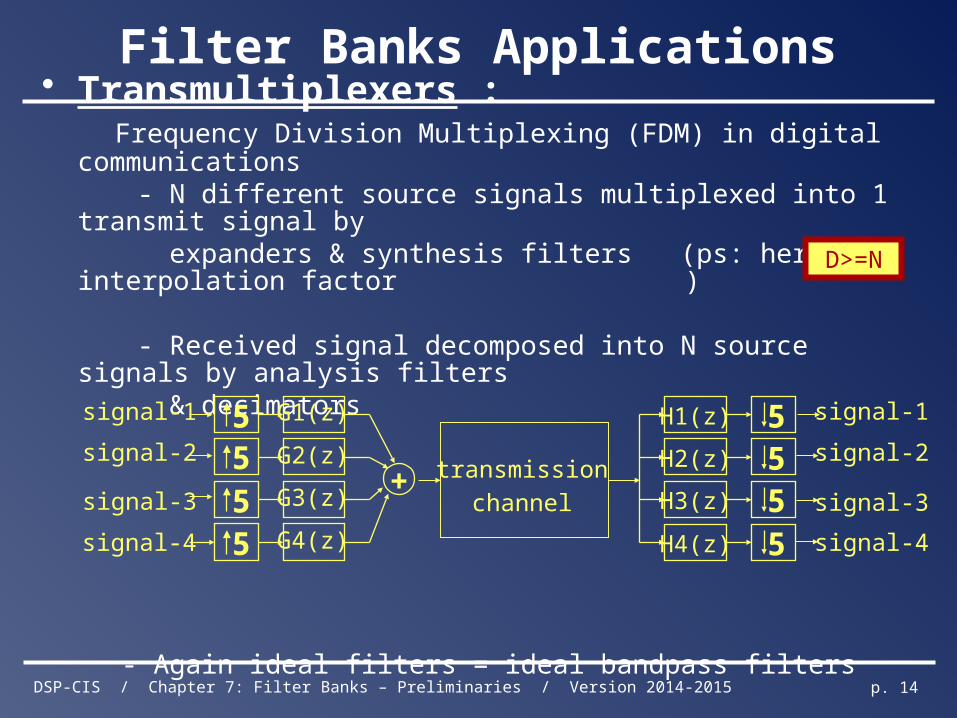
Filter Banks Applications
• Transmultiplexers : Frequency Division Multiplexing (FDM) in digital communications - N different source signals multiplexed into 1 transmit signal by expanders & synthesis filters (ps: here interpolation
factor )
- Received signal decomposed into N source signals by analysis filters & decimators
- Again ideal filters = ideal bandpass filters
5 G1(z)
5 G2(z)
5 G3(z)
5 G4(z)
+
5H1(z)
5H2(z)
5H3(z)
5H4(z)
transmission
channel
signal-1
signal-2
signal-3
signal-4
signal-1
signal-2
signal-3
signal-4
D>=N
DSP-CIS / Chapter 7: Filter Banks – Preliminaries / Version 2014-2015 p. 15
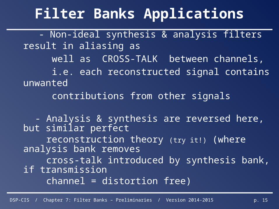
- Non-ideal synthesis & analysis filters result in aliasing as
well as CROSS-TALK between channels,
i.e. each reconstructed signal contains unwanted
contributions from other signals
- Analysis & synthesis are reversed here, but similar perfect
reconstruction theory (try it!) (where analysis bank removes cross-talk introduced by synthesis bank, if transmission channel = distortion free)
Filter Banks Applications
DSP-CIS / Chapter 7: Filter Banks – Preliminaries / Version 2014-2015 p. 16
Filter Banks Applications
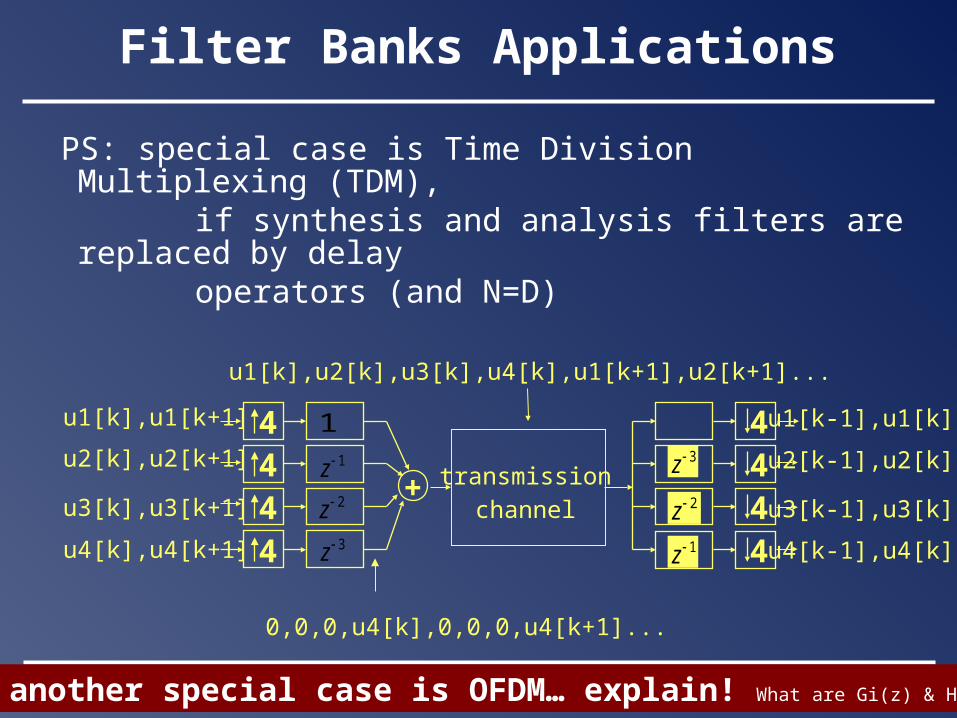
PS: special case is Time Division Multiplexing (TDM), if synthesis and analysis filters are replaced by delay operators (and N=D)
4444
+444
transmission
channel
1z2z3z
1
1z
2z
3z
u1[k],u1[k+1]
u2[k],u2[k+1]
u3[k],u3[k+1]
u4[k],u4[k+1]
u1[k],u2[k],u3[k],u4[k],u1[k+1],u2[k+1]...
4 u1[k-1],u1[k]
u2[k-1],u2[k]
u3[k-1],u3[k]
u4[k-1],u4[k]
4z
0,0,0,u4[k],0,0,0,u4[k+1]...
PS: another special case is OFDM… explain! What are Gi(z) & Hi(z) ?
DSP-CIS / Chapter 7: Filter Banks – Preliminaries / Version 2014-2015 p. 17
Filter Banks Applications
PS : special case is Code Division Multiple Access (CDMA), where filter coefficients=(orthogonal) user codes CDMA basics: (see digital coms courses)…… -Each user (n=1..N) is assigned a length-N pseudo-random code sequence
-Transmission : For each symbol (k-th symbol for user-n), a `chip’ sequence is transmitted
-Mostly binary codes ( ) with BPSK/QPSK symbols -Multiple access based on code-orthogonality (see below)Skip th
is slide
DSP-CIS / Chapter 7: Filter Banks – Preliminaries / Version 2014-2015 p. 18
CDMA basics: -Reception : If (x) received signal = transmitted chip sequence (i.e. no
channel effect, no noise), multiply chips with (synchronized) code
sequence + sum.
-Example (user i)
transmitted symbols +1……… -1………. -1……… +1………
code sequence +1,+1,-1,-1
transmitted chips +1,+1,-1,-1 -1,-1,+1,+1 -1,-1,+1,+1 +1,+1,-1,-1
received chips +1,+1,-1,-1 -1,-1,+1,+1 -1,-1,+1,+1 +1,+1,-1,-1
+1,+1,-1,-1 (mult. with code & sum)
received symbols (*1/4) +1………… -1…….…..-1…………+1
(x) PS: real-world CDMA is considerably more complicated (different channels for different users + channel dispersion, asynchronous users, scrambling codes, etc.)
Filter Banks Applications
Skip this slid
e
DSP-CIS / Chapter 7: Filter Banks – Preliminaries / Version 2014-2015 p. 19
Filter Banks Applications
CDMA Transmission/reception block scheme :
-transmitter code-multiplication may be viewed as filtering operation,
with FIR transmit filter
-receiver code-multiplication & summation may be viewed as filtering
operation, with receive filter
-PR for `flat’ channel H(z)=1 and if codes are orthogonal (prove it!)
4444
+444
transmission
channel
)(4 zC
u1[k],u1[k+1]
u2[k],u2[k+1]
u3[k],u3[k+1]
u4[k],u4[k+1]
u2[k+1],u2[k])( 12 zC
)(3 zC
)(2 zC
)(1 zC 4
Bas
e st
atio
n
Use
r-2
term
ina
l
Skip this slid
e
DSP-CIS / Chapter 7: Filter Banks – Preliminaries / Version 2014-2015 p. 20
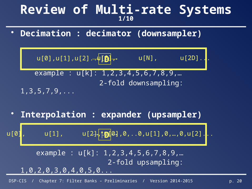
Review of Multi-rate Systems 1/10
• Decimation : decimator (downsampler)
example : u[k]: 1,2,3,4,5,6,7,8,9,…
2-fold downsampling: 1,3,5,7,9,...
• Interpolation : expander (upsampler)
example : u[k]: 1,2,3,4,5,6,7,8,9,… 2-fold upsampling: 1,0,2,0,3,0,4,0,5,0...
D u[0], u[N], u[2D]...u[0],u[1],u[2]...
D u[0],0,..0,u[1],0,…,0,u[2]...u[0], u[1], u[2],...
DSP-CIS / Chapter 7: Filter Banks – Preliminaries / Version 2014-2015 p. 21
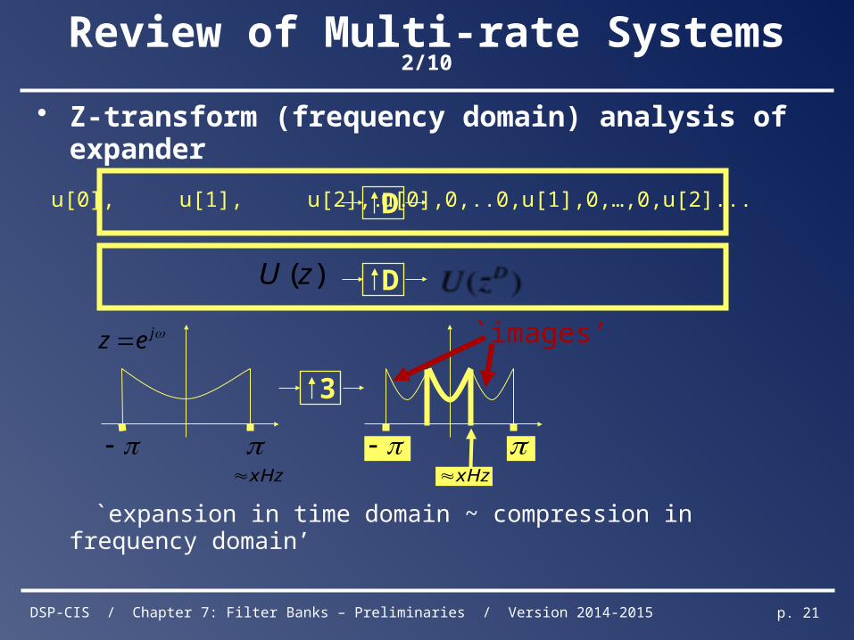
Review of Multi-rate Systems 2/10
• Z-transform (frequency domain) analysis of expander
`expansion in time domain ~ compression in frequency domain’
D u[0],0,..0,u[1],0,…,0,u[2]...u[0], u[1], u[2],...
D)(zU
jez
3
xHz
`images’
xHz
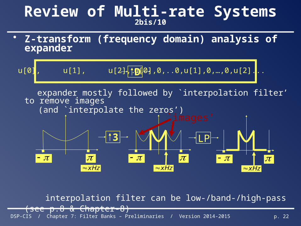
DSP-CIS / Chapter 7: Filter Banks – Preliminaries / Version 2014-2015 p. 22
Review of Multi-rate Systems 2bis/10
• Z-transform (frequency domain) analysis of expander
expander mostly followed by `interpolation filter’ to remove images (and `interpolate the zeros’)
interpolation filter can be low-/band-/high-pass (see p.8 & Chapter-8)
D u[0],0,..0,u[1],0,…,0,u[2]...u[0], u[1], u[2],...
3
xHz
`images’
xHz
xHz
LP
DSP-CIS / Chapter 7: Filter Banks – Preliminaries / Version 2014-2015 p. 23
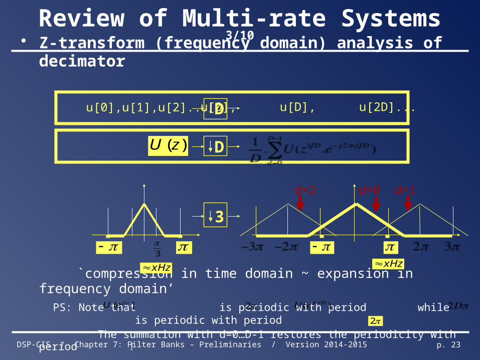
Review of Multi-rate Systems 3/10
• Z-transform (frequency domain) analysis of decimator
`compression in time domain ~ expansion in frequency domain’ PS: Note that is periodic with period while is periodic with period
The summation with d=0…D-1 restores the periodicity with period !
D)(zU
D u[0], u[D], u[2D]...u[0],u[1],u[2]...
d=0d=2 d=1
3
xHz
3
xHz
)( jeU 2
2
DSP-CIS / Chapter 7: Filter Banks – Preliminaries / Version 2014-2015 p. 24
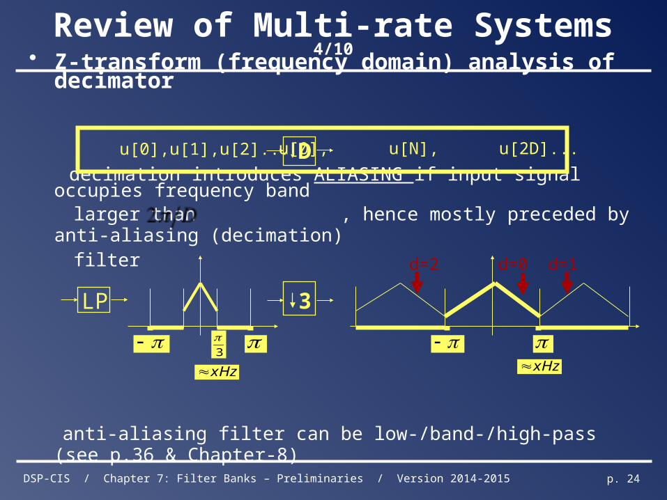
Review of Multi-rate Systems 4/10
• Z-transform (frequency domain) analysis of decimator
decimation introduces ALIASING if input signal occupies frequency band larger than , hence mostly preceded by anti-aliasing (decimation) filter
anti-aliasing filter can be low-/band-/high-pass (see p.36 & Chapter-8)
D u[0], u[N], u[2D]...u[0],u[1],u[2]...
LP
d=0d=2 d=1
3
xHz
3
xHz
DSP-CIS / Chapter 7: Filter Banks – Preliminaries / Version 2014-2015 p. 25
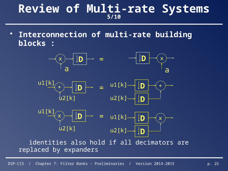
Review of Multi-rate Systems 5/10
• Interconnection of multi-rate building blocks :
identities also hold if all decimators are replaced by expanders
D x
aDx
a=
=
=
D+
u2[k]
Dx
u2[k]
u1[k]
u1[k]
D +
Du2[k]
u1[k]
D x
Du2[k]
u1[k]
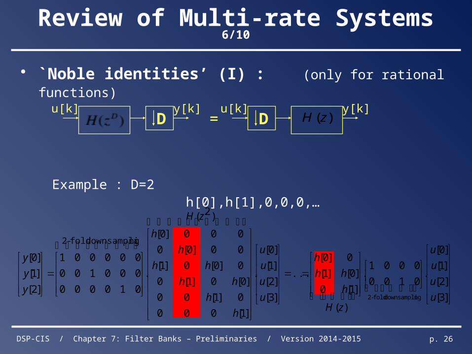
DSP-CIS / Chapter 7: Filter Banks – Preliminaries / Version 2014-2015 p. 26
Review of Multi-rate Systems 6/10
• `Noble identities’ (I) : (only for rational functions)
Example : D=2 h[0],h[1],0,0,0,…
=D D )(zHu[k] u[k]y[k] y[k]
]3[
]2[
]1[
]0[
.0100
0001.
)(
]1[0
]0[]1[
0]0[
...
]3[
]2[
]1[
]0[
.
)2(
]1[000
0]1[00
]0[0]1[0
0]0[0]1[
00]0[0
000]0[
.
010000
000100
000001
]2[
]1[
]0[
ngdownsampli fold-2
ngdownsampli fold-2
u
u
u
u
zH
h
hh
h
u
u
u
u
zH
h
h
hh
hh
h
h
y
y
y
DSP-CIS / Chapter 7: Filter Banks – Preliminaries / Version 2014-2015 p. 27
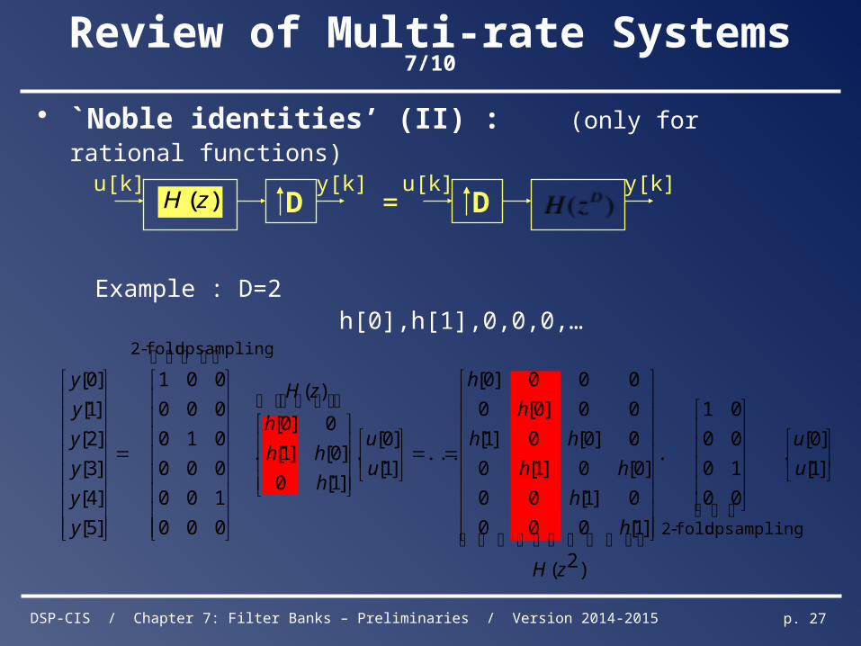
Review of Multi-rate Systems 7/10
• `Noble identities’ (II) : (only for rational functions)
Example : D=2 h[0],h[1],0,0,0,…
=D D)(zHu[k] u[k]y[k] y[k]
]1[
]0[.
00
10
00
01
.
)2(
]1[000
0]1[00
]0[0]1[0
0]0[0]1[
00]0[0
000]0[
...]1[
]0[.
)(
]1[0
]0[]1[
0]0[
.
000
100
000
010
000
001
]5[
]4[
]3[
]2[
]1[
]0[
upsampling fold-2
upsampling fold-2
u
u
zH
h
h
hh
hh
h
h
u
u
zH
h
hh
h
y
y
y
y
y
y
DSP-CIS / Chapter 7: Filter Banks – Preliminaries / Version 2014-2015 p. 28
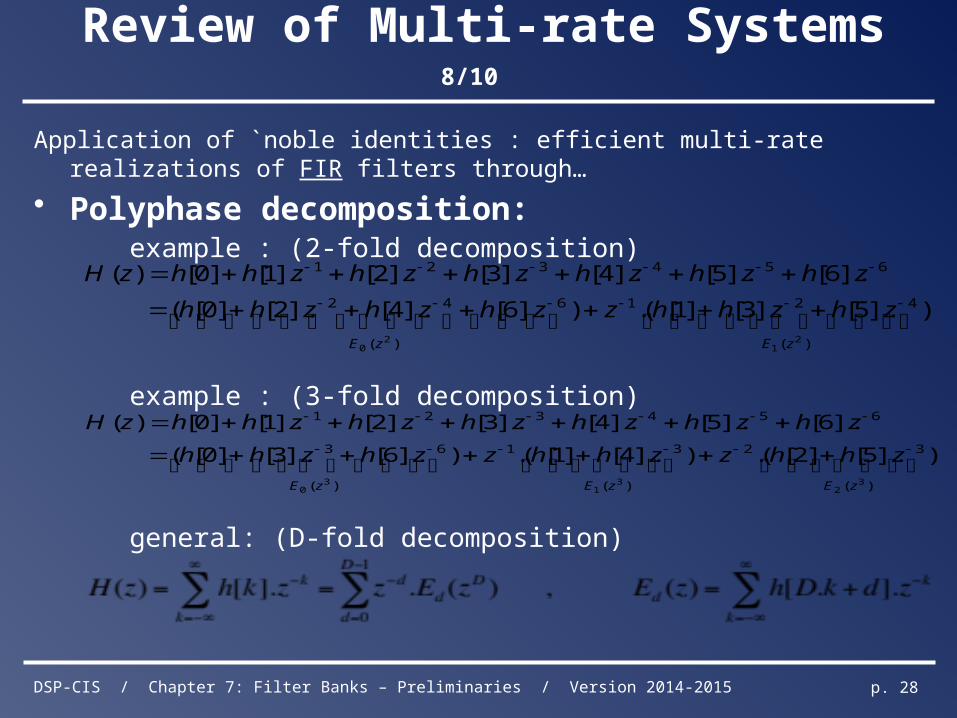
Review of Multi-rate Systems 8/10
Application of `noble identities : efficient multi-rate realizations of FIR filters through…
• Polyphase decomposition: example : (2-fold decomposition)
example : (3-fold decomposition)
general: (D-fold decomposition)
)(
421
)(
642
654321
21
20
)].5[].3[]1[(.)].6[].4[].2[]0[(
].6[].5[].4[].3[].2[].1[]0[)(
zEzE
zhzhhzzhzhzhh
zhzhzhzhzhzhhzH
)(
32
)(
31
)(
63
654321
32
31
30
)].5[]2[(.)].4[]1[(.)].6[].3[]0[(
].6[].5[].4[].3[].2[].1[]0[)(
zEzEzE
zhhzzhhzzhzhh
zhzhzhzhzhzhhzH
DSP-CIS / Chapter 7: Filter Banks – Preliminaries / Version 2014-2015 p. 29
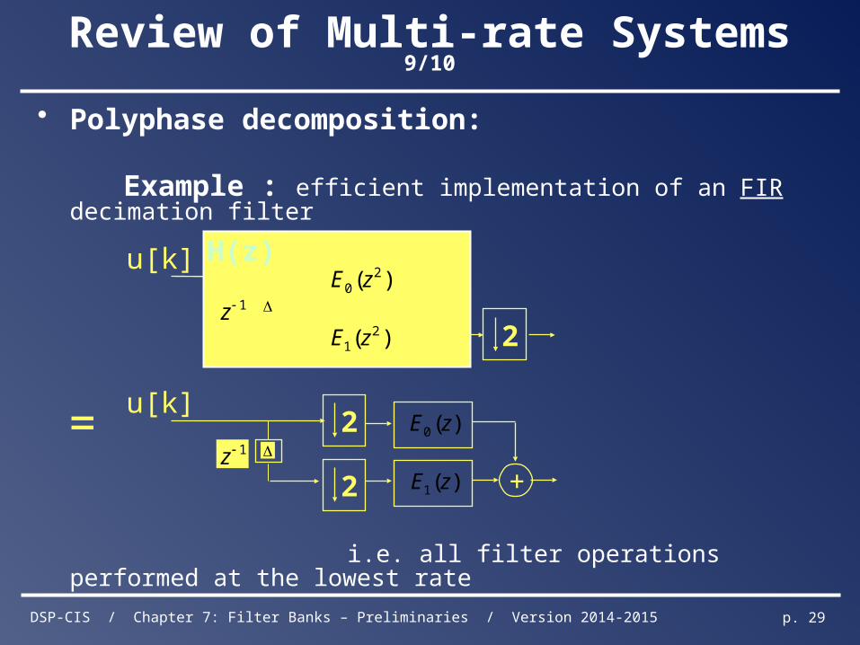
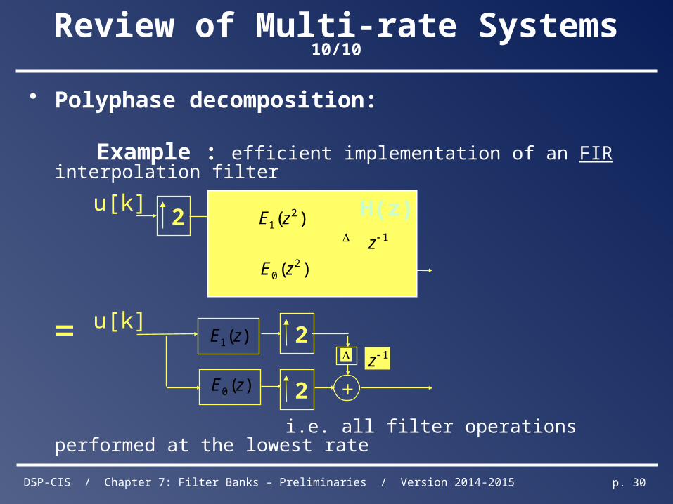
Review of Multi-rate Systems 9/10
• Polyphase decomposition: Example : efficient implementation of an FIR decimation filter
i.e. all filter operations performed at the lowest rate
u[k]
2
)( 20 zE
)( 21 zE
1z+
H(z)
u[k]
2
1z
)(0 zE
)(1 zE +
= 2
DSP-CIS / Chapter 7: Filter Banks – Preliminaries / Version 2014-2015 p. 30
Review of Multi-rate Systems 10/10
• Polyphase decomposition:
Example : efficient implementation of an FIR interpolation filter
i.e. all filter operations performed at the lowest rate
=
u[k]
2
)( 20 zE
)( 21 zE
1z
+
H(z)
u[k]
2
1z
+)(0 zE
)(1 zE
2
DSP-CIS / Chapter 7: Filter Banks – Preliminaries / Version 2014-2015 p. 31
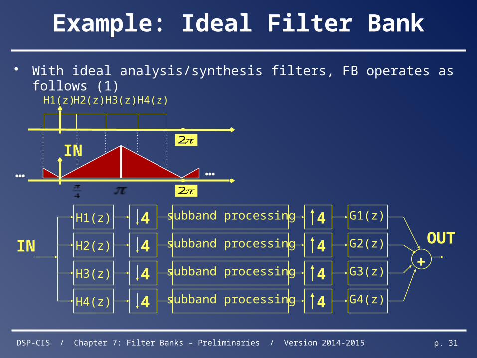
Example: Ideal Filter Bank
• With ideal analysis/synthesis filters, FB operates as follows (1)
subband processing 4H1(z)
subband processing 4H2(z)
subband processing 4H3(z)
4
4
4
4 subband processing 4H4(z)
IN
G1(z)
G2(z)
G3(z)
G4(z)
+
OUT
2
H1(z) H2(z) H3(z) H4(z)
IN
2
……
DSP-CIS / Chapter 7: Filter Banks – Preliminaries / Version 2014-2015 p. 32
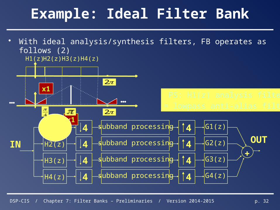
Example: Ideal Filter Bank
• With ideal analysis/synthesis filters, FB operates as follows (2)
subband processing 4H1(z)
subband processing 4H2(z)
subband processing 4H3(z)
4
4
4
4 subband processing 4H4(z)
IN
G1(z)
G2(z)
G3(z)
G4(z)
+
OUT
2
H1(z) H2(z) H3(z) H4(z)
x1
x1
2
……PS: H1(z) analysis filter
≈ lowpass anti-alias filter
DSP-CIS / Chapter 7: Filter Banks – Preliminaries / Version 2014-2015 p. 33
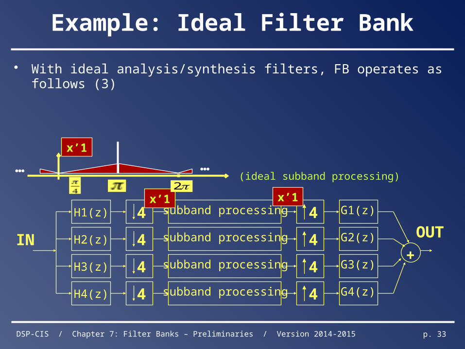
Example: Ideal Filter Bank
• With ideal analysis/synthesis filters, FB operates as follows (3)
subband processing 4H1(z)
subband processing 4H2(z)
subband processing 4H3(z)
4
4
4
4 subband processing 4H4(z)
IN
G1(z)
G2(z)
G3(z)
G4(z)
+
OUT
x’1 x’1
(ideal subband processing)
x’1
2
……
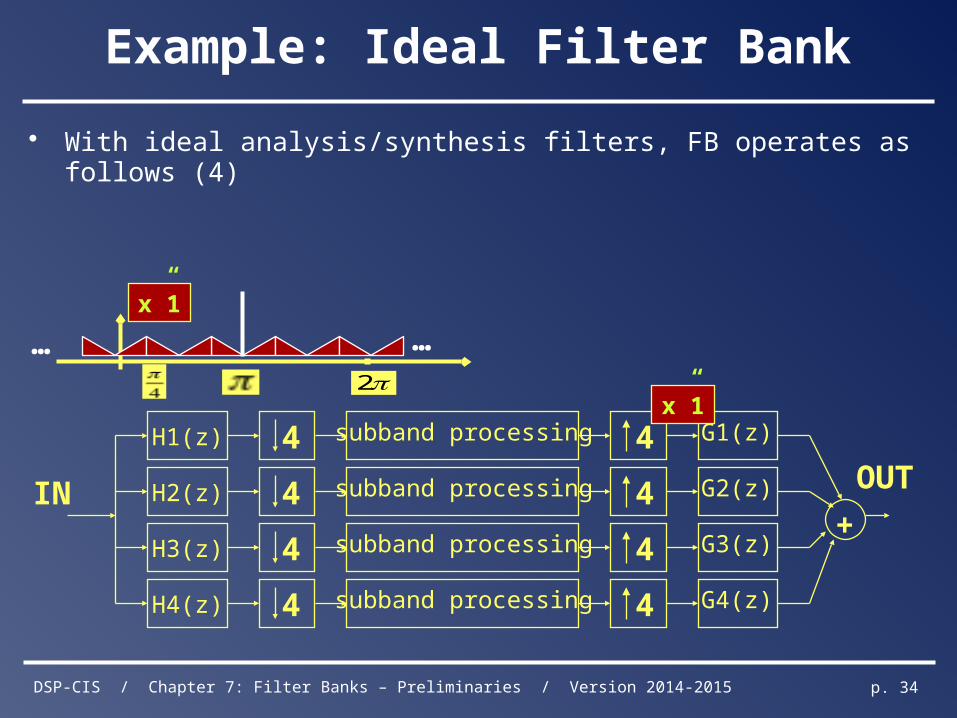
DSP-CIS / Chapter 7: Filter Banks – Preliminaries / Version 2014-2015 p. 34
Example: Ideal Filter Bank
• With ideal analysis/synthesis filters, FB operates as follows (4)
subband processing 4H1(z)
subband processing 4H2(z)
subband processing 4H3(z)
4
4
4
4 subband processing 4H4(z)
IN
G1(z)
G2(z)
G3(z)
G4(z)
+
OUT
x”1
x”1
2
……
DSP-CIS / Chapter 7: Filter Banks – Preliminaries / Version 2014-2015 p. 35
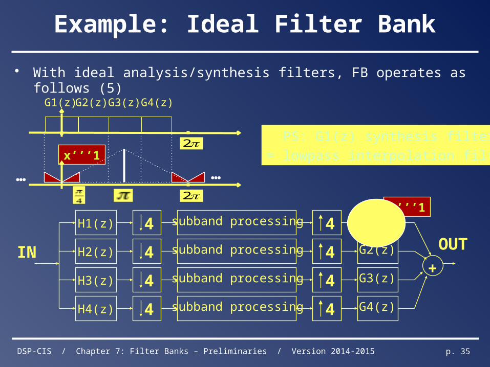
Example: Ideal Filter Bank
• With ideal analysis/synthesis filters, FB operates as follows (5)
subband processing 4H1(z)
subband processing 4H2(z)
subband processing 4H3(z)
4
4
4
4 subband processing 4H4(z)
IN
G1(z)
G2(z)
G3(z)
G4(z)
+
OUT
2
G1(z) G2(z) G3(z) G4(z)
x’’’1
x’’’1
2
……
PS: G1(z) synthesis filter
≈ lowpass interpolation filter
DSP-CIS / Chapter 7: Filter Banks – Preliminaries / Version 2014-2015 p. 36
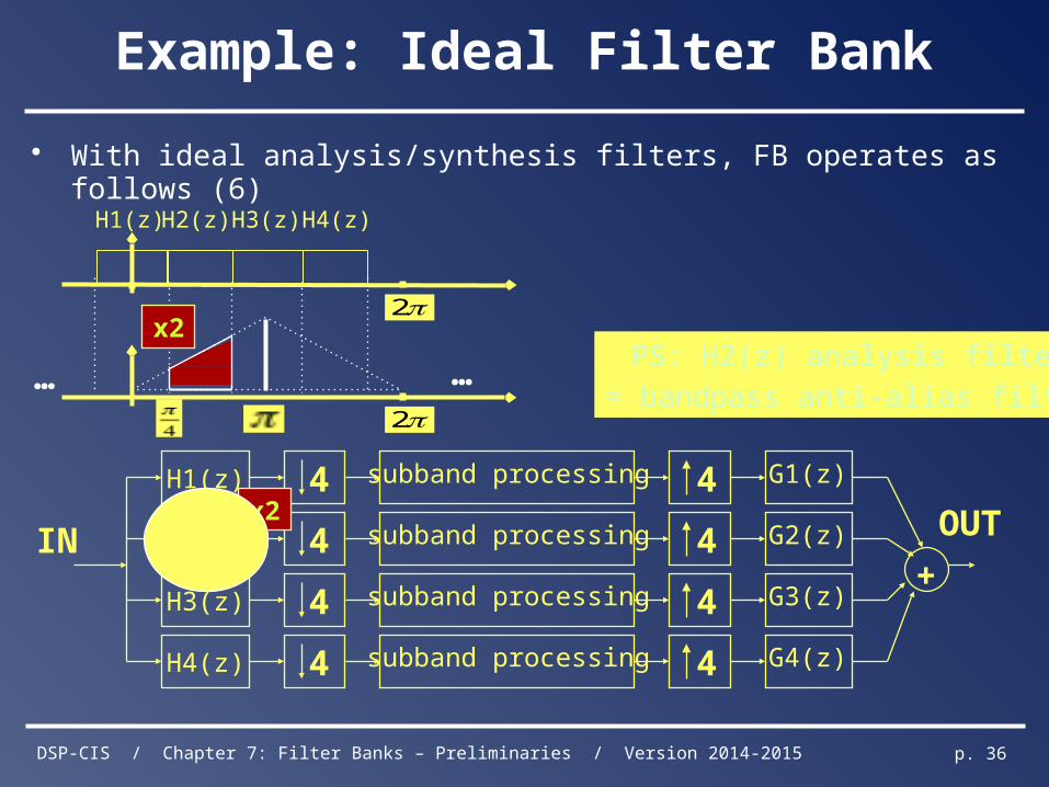
Example: Ideal Filter Bank
• With ideal analysis/synthesis filters, FB operates as follows (6)
subband processing 4H1(z)
subband processing 4H2(z)
subband processing 4H3(z)
4
4
4
4 subband processing 4H4(z)
IN
G1(z)
G2(z)
G3(z)
G4(z)
+
OUTx2
2
……
2
H1(z) H2(z) H3(z) H4(z)
x2PS: H2(z) analysis filter
≈ bandpass anti-alias filter
DSP-CIS / Chapter 7: Filter Banks – Preliminaries / Version 2014-2015 p. 37
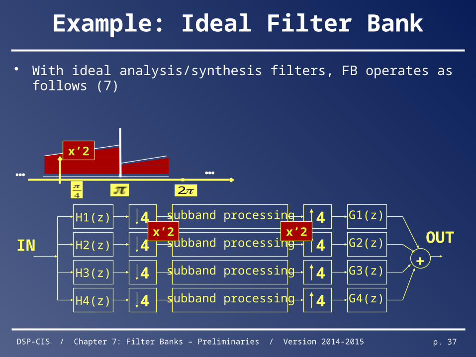
Example: Ideal Filter Bank
• With ideal analysis/synthesis filters, FB operates as follows (7)
subband processing 4H1(z)
subband processing 4H2(z)
subband processing 4H3(z)
4
4
4
4 subband processing 4H4(z)
IN
G1(z)
G2(z)
G3(z)
G4(z)
+
OUTx’2 x’2
2
……x’2
DSP-CIS / Chapter 7: Filter Banks – Preliminaries / Version 2014-2015 p. 38
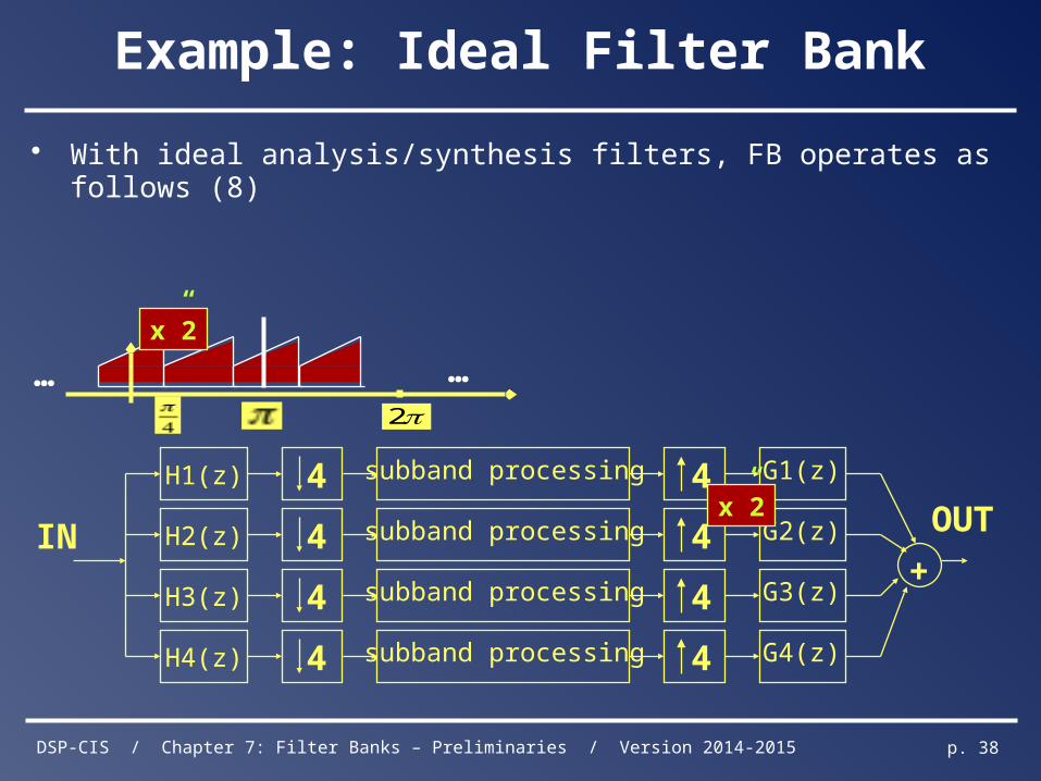
Example: Ideal Filter Bank
• With ideal analysis/synthesis filters, FB operates as follows (8)
subband processing 4H1(z)
subband processing 4H2(z)
subband processing 4H3(z)
4
4
4
4 subband processing 4H4(z)
IN
G1(z)
G2(z)
G3(z)
G4(z)
+
OUTx”2
IN
2
……x”2
DSP-CIS / Chapter 7: Filter Banks – Preliminaries / Version 2014-2015 p. 39
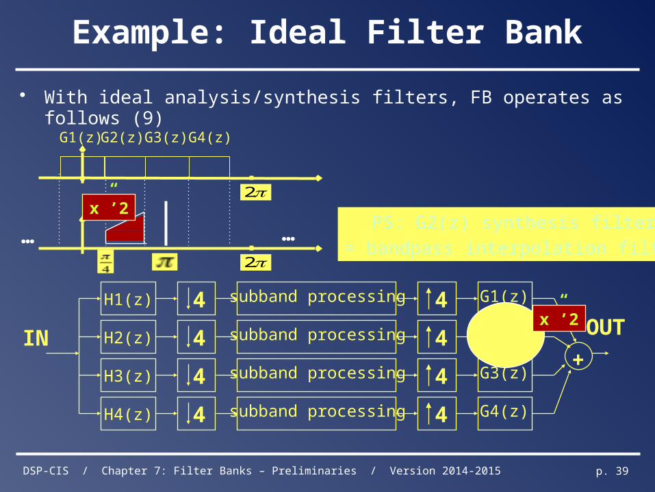
Example: Ideal Filter Bank
• With ideal analysis/synthesis filters, FB operates as follows (9)
subband processing 4H1(z)
subband processing 4H2(z)
subband processing 4H3(z)
4
4
4
4 subband processing 4H4(z)
IN
G1(z)
G2(z)
G3(z)
G4(z)
+
OUT
2
……PS: G2(z) synthesis filter
≈ bandpass interpolation filter
2
G1(z) G2(z) G3(z) G4(z)
x”’2
x”’2
DSP-CIS / Chapter 7: Filter Banks – Preliminaries / Version 2014-2015 p. 40
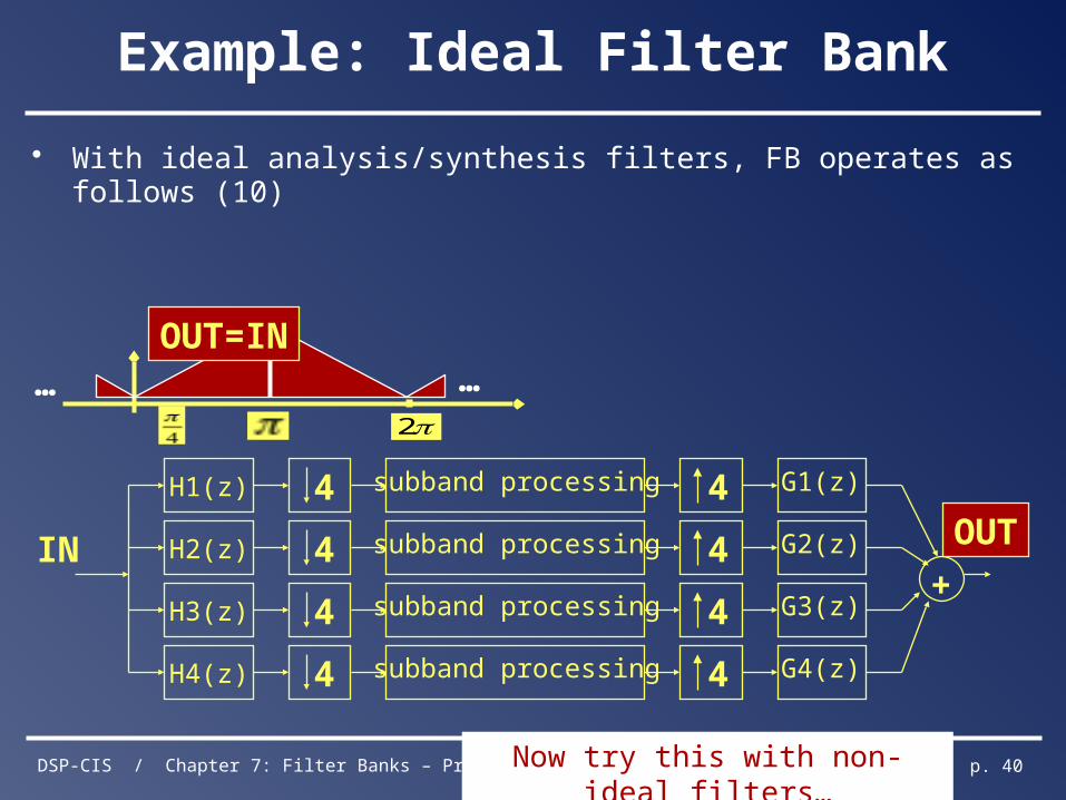
Example: Ideal Filter Bank
• With ideal analysis/synthesis filters, FB operates as follows (10)
subband processing 4H1(z)
subband processing 4H2(z)
subband processing 4H3(z)
4
4
4
4 subband processing 4H4(z)
IN
G1(z)
G2(z)
G3(z)
G4(z)
+
OUT
Now try this with non-ideal filters…
2
……OUT=IN