Embed Size (px)
Citation preview
DSP-CIS
Chapter-8: Maximally Decimated PR-FBs
Marc MoonenDept. E.E./ESAT-STADIUS, KU Leuven
www.esat.kuleuven.be/stadius/
DSP-CIS / Chapter-8: Maximally Decimated PR-FBs / Version 2014-2015 p. 2
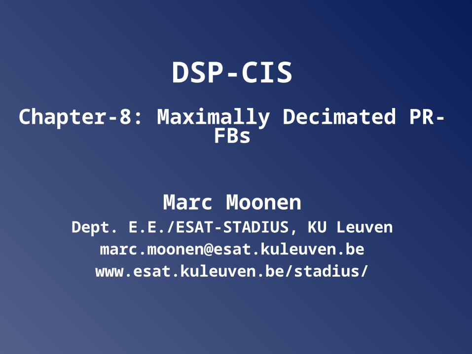
: Preliminaries• Filter bank (FB) set-up and applications • Perfect reconstruction (PR) problem • Multi-rate systems review (=10 slides)• Example: Ideal filter bank (=10 figures)
: Maximally Decimated PR-FBs• Example: DFT/IDFT filter bank• Perfect reconstruction theory• Paraunitary PR-FBs
: DFT-Modulated FBs• Maximally decimated DFT-modulated FBs• Oversampled DFT-modulated FBs
: Special Topics• Cosine-modulated FBs• Non-uniform FBs & Wavelets• Frequency domain filtering
Chapter-7
Chapter-8
Chapter-9
Chapter-10
Part-III : Filter Banks
DSP-CIS / Chapter-8: Maximally Decimated PR-FBs / Version 2014-2015 p. 3
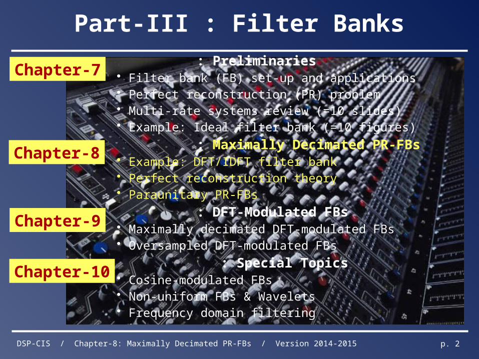
General `subband processing’ set-up (Chapter-7) : PS: subband processing ignored in filter bank design
Refresh (1)
subband processing 3H0(z)
subband processing 3H1(z)
subband processing 3H2(z)
3
3
3
3 subband processing 3H3(z)
IN
F0(z)
F1(z)
F2(z)
F3(z)
+
OUT
downsampling/decimation
analysis bank synthesis bank
upsampling/expansion
DSP-CIS / Chapter-8: Maximally Decimated PR-FBs / Version 2014-2015 p. 4
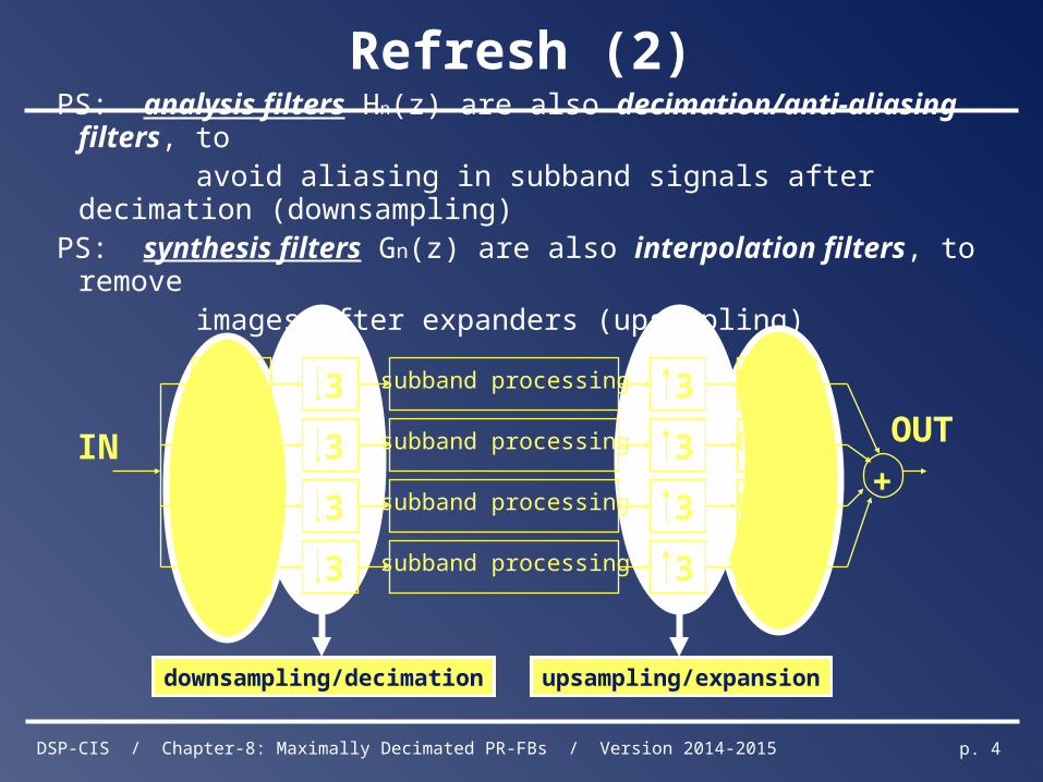
PS: analysis filters Hn(z) are also decimation/anti-aliasing filters, to avoid aliasing in subband signals after decimation (downsampling) PS: synthesis filters Gn(z) are also interpolation filters, to remove images after expanders (upsampling)
downsampling/decimation upsampling/expansion
Refresh (2)
subband processing 3H0(z)
subband processing 3H1(z)
subband processing 3H2(z)
3
3
3
3 subband processing 3H3(z)
IN
F0(z)
F1(z)
F2(z)
F3(z)
+
OUT
DSP-CIS / Chapter-8: Maximally Decimated PR-FBs / Version 2014-2015 p. 5
Refresh (3)
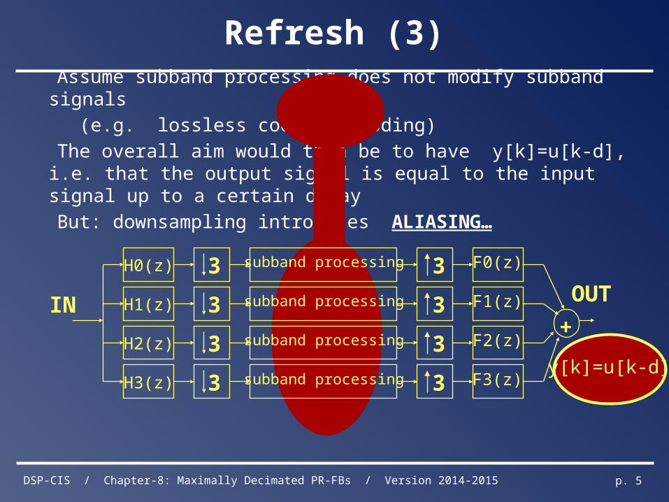
Assume subband processing does not modify subband signals
(e.g. lossless coding/decoding)
The overall aim would then be to have y[k]=u[k-d], i.e. that the output signal is equal to the input signal up to a certain delay
But: downsampling introduces ALIASING…
subband processing 3H0(z)
subband processing 3H1(z)
subband processing 3H2(z)
3
3
3
3 subband processing 3H3(z)
IN
F0(z)
F1(z)
F2(z)
F3(z)
+
OUT
y[k]=u[k-d]?
DSP-CIS / Chapter-8: Maximally Decimated PR-FBs / Version 2014-2015 p. 6
Refresh (4)
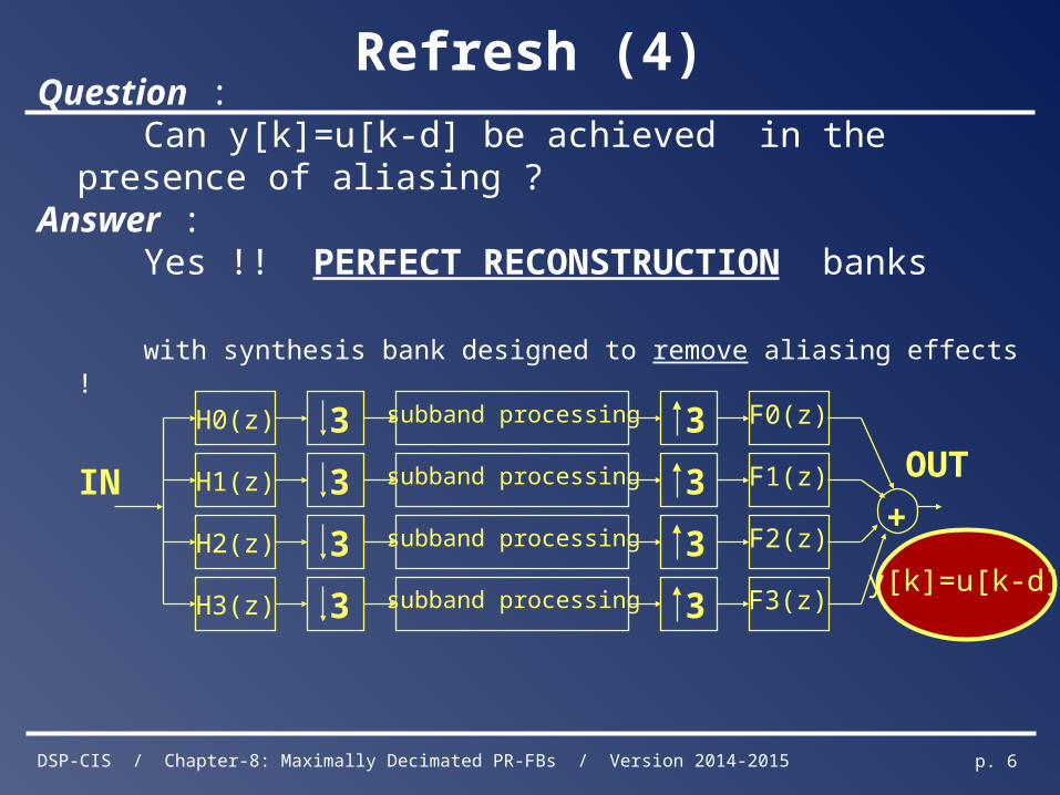
Question : Can y[k]=u[k-d] be achieved in the presence of aliasing ?Answer : Yes !! PERFECT RECONSTRUCTION banks with synthesis bank designed to remove aliasing effects !
subband processing 3H0(z)
subband processing 3H1(z)
subband processing 3H2(z)
3
3
3
3 subband processing 3H3(z)
IN
F0(z)
F1(z)
F2(z)
F3(z)
+
OUT
y[k]=u[k-d]?
DSP-CIS / Chapter-8: Maximally Decimated PR-FBs / Version 2014-2015 p. 7
Refresh (5)
Two design issues :
✪ Filter specifications, e.g. stopband attenuation,
passband ripple, transition band, etc.
(for each (analysis) filter!)
✪ Perfect reconstruction (PR) property.
Challenge will be in addressing these two design issues at once (‘PR only’ (without filter specs) is easy, see next slides)
This chapter : Maximally decimated FB’s :
DSP-CIS / Chapter-8: Maximally Decimated PR-FBs / Version 2014-2015 p. 8
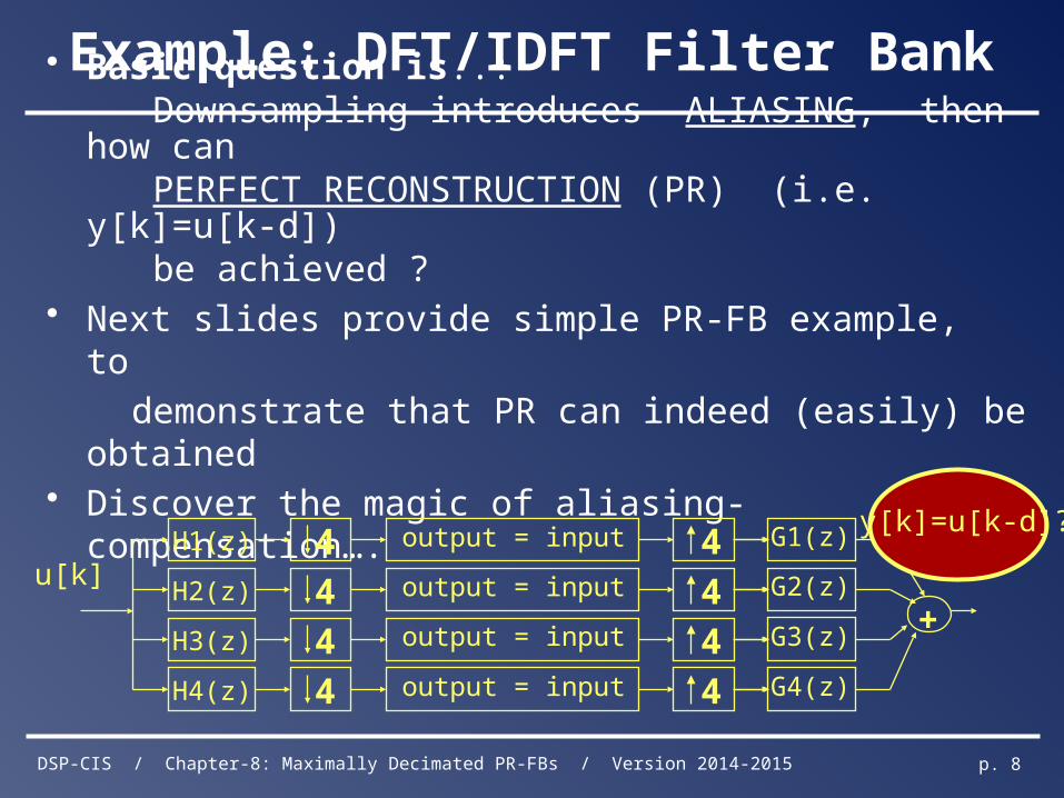
Example: DFT/IDFT Filter Bank
• Basic question is..: Downsampling introduces ALIASING, then how can PERFECT RECONSTRUCTION (PR) (i.e. y[k]=u[k-d]) be achieved ?• Next slides provide simple PR-FB example, to
demonstrate that PR can indeed (easily) be obtained• Discover the magic of aliasing-compensation….
G1(z)
G2(z)
G3(z)
G4(z)
+
output = input 4H1(z)
output = input 4H2(z)
output = input 4H3(z)
4
4
4
4 output = input 4H4(z)
u[k]
y[k]=u[k-d]?
DSP-CIS / Chapter-8: Maximally Decimated PR-FBs / Version 2014-2015 p. 9
Example: DFT/IDFT Filter Bank
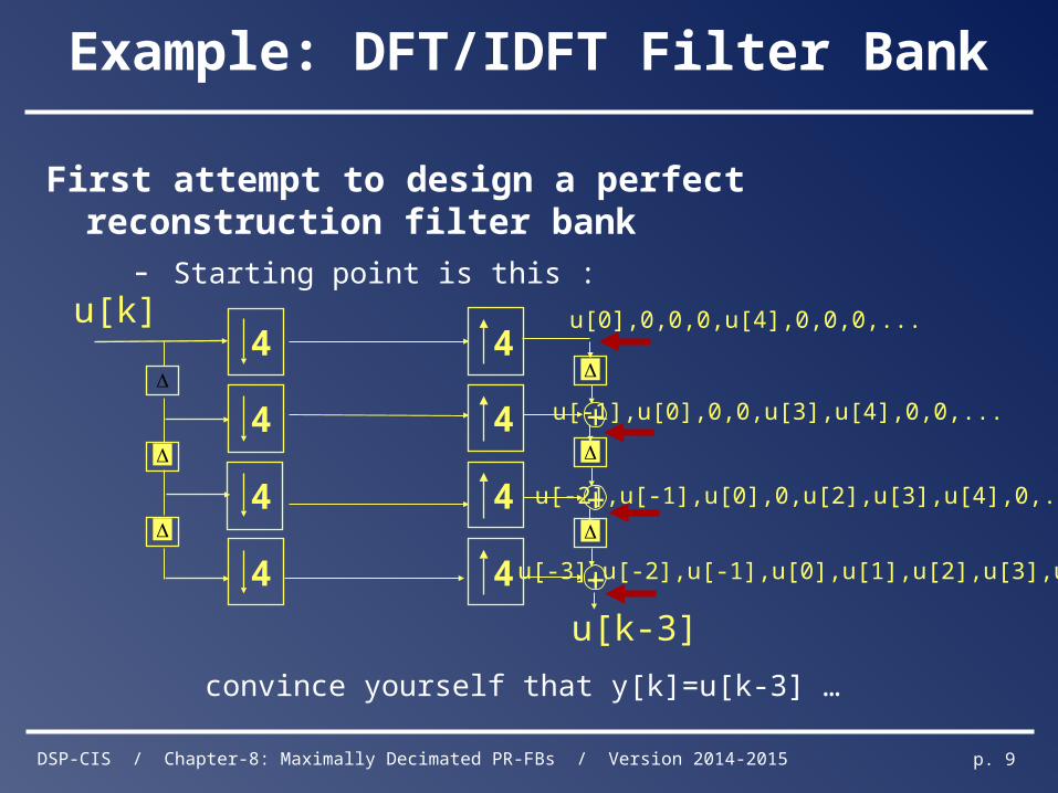
First attempt to design a perfect reconstruction filter bank
- Starting point is this :
convince yourself that y[k]=u[k-3] …
4
4
4
4
u[k]
4
4
4
4
+
+
+u[k-3]
u[0],0,0,0,u[4],0,0,0,...
u[-1],u[0],0,0,u[3],u[4],0,0,...
u[-2],u[-1],u[0],0,u[2],u[3],u[4],0,...
u[-3],u[-2],u[-1],u[0],u[1],u[2],u[3],u[4],...
DSP-CIS / Chapter-8: Maximally Decimated PR-FBs / Version 2014-2015 p. 10
Example: DFT/IDFT Filter Bank
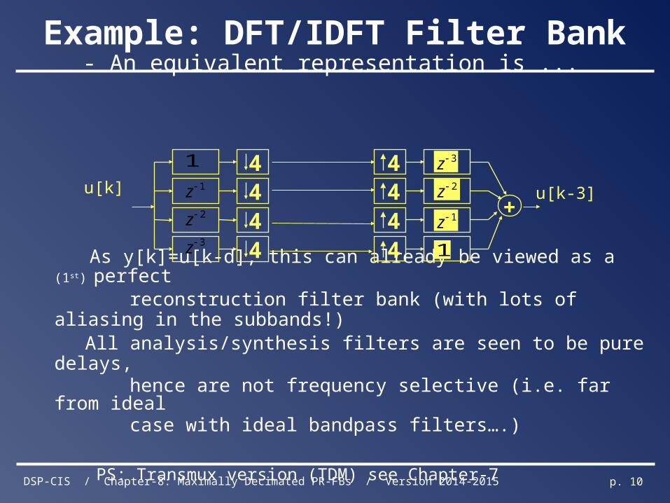
- An equivalent representation is ...
As y[k]=u[k-d], this can already be viewed as a (1st) perfect reconstruction filter bank (with lots of aliasing in the subbands!) All analysis/synthesis filters are seen to be pure delays, hence are not frequency selective (i.e. far from ideal case with ideal bandpass filters….)
PS: Transmux version (TDM) see Chapter-7
4444
+1z2z3z
1
u[k-3]444
1z
2z
3z4
1
u[k]
DSP-CIS / Chapter-8: Maximally Decimated PR-FBs / Version 2014-2015 p. 11
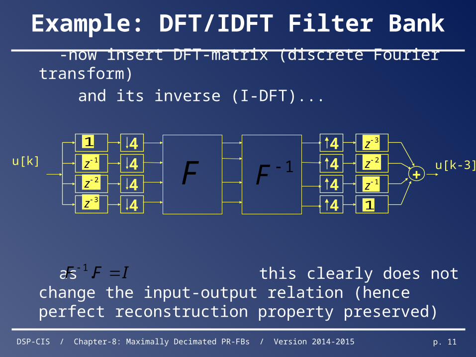
Example: DFT/IDFT Filter Bank
-now insert DFT-matrix (discrete Fourier transform)
and its inverse (I-DFT)...
as this clearly does not change the input-output relation (hence perfect reconstruction property preserved)
4444
+u[k-3]
1z
2z
3z
1
1z2z3z
1
444
4u[k]
F 1F
IFF .1
DSP-CIS / Chapter-8: Maximally Decimated PR-FBs / Version 2014-2015 p. 12
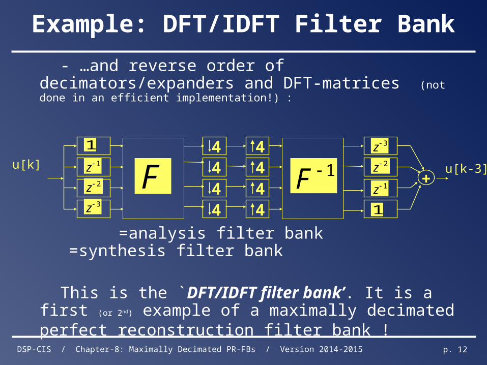
Example: DFT/IDFT Filter Bank
- …and reverse order of decimators/expanders and DFT-matrices (not done in an efficient implementation!) :
=analysis filter bank =synthesis filter bank
This is the `DFT/IDFT filter bank’. It is a first (or 2nd) example of a maximally decimated perfect reconstruction filter bank !
4444
1z2z3z
1
u[k] 444
4
F +u[k-3]
1z
2z
3z
1
1F
DSP-CIS / Chapter-8: Maximally Decimated PR-FBs / Version 2014-2015 p. 13
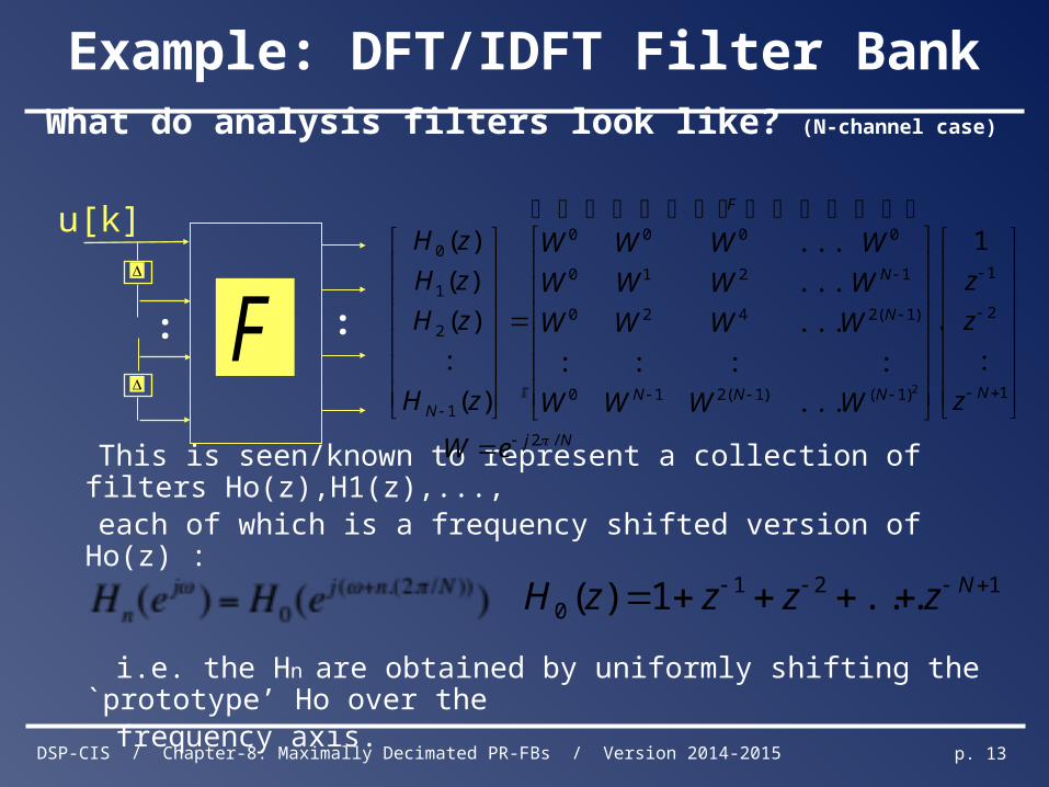
Example: DFT/IDFT Filter Bank
What do analysis filters look like? (N-channel case)
This is seen/known to represent a collection of filters Ho(z),H1(z),..., each of which is a frequency shifted version of Ho(z) :
i.e. the Hn are obtained by uniformly shifting the `prototype’ Ho over the frequency axis.
F
u[k]
Nj
N
F
NNN
N
N
N
eW
z
z
z
WWWW
WWWW
WWWW
WWWW
zH
zH
zH
zH
/2
1
2
1
)1()1(210
)1(2420
1210
0000
1
2
1
0
:
1
.
...
::::
...
...
...
)(
:
)(
)(
)(
2
1210 ...1)( NzzzzH
: :
DSP-CIS / Chapter-8: Maximally Decimated PR-FBs / Version 2014-2015 p. 14
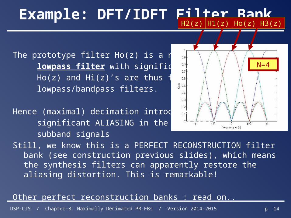
Example: DFT/IDFT Filter Bank
The prototype filter Ho(z) is a not-so-great
lowpass filter with significant sidelobes.
Ho(z) and Hi(z)’s are thus far from ideal
lowpass/bandpass filters.
Hence (maximal) decimation introduces
significant ALIASING in the decimated
subband signals
Still, we know this is a PERFECT RECONSTRUCTION filter bank (see construction previous slides), which means the synthesis filters can apparently restore the aliasing distortion. This is remarkable!
Other perfect reconstruction banks : read on..
Ho(z)H1(z)
N=4
H3(z)H2(z)
DSP-CIS / Chapter-8: Maximally Decimated PR-FBs / Version 2014-2015 p. 15
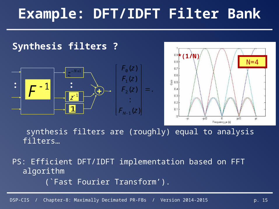
Example: DFT/IDFT Filter Bank
Synthesis filters ?
synthesis filters are (roughly) equal to analysis filters…
PS: Efficient DFT/IDFT implementation based on FFT algorithm
(`Fast Fourier Transform’).
...
)(
:
)(
)(
)(
1
2
1
0
zF
zF
zF
zF
N
+1z
1
1F
*(1/N)N=4
::
DSP-CIS / Chapter-8: Maximally Decimated PR-FBs / Version 2014-2015 p. 16
Perfect Reconstruction Theory
Now comes the hard part…(?)
✪ 2-channel case:
Examples…
✪ N-channel case:
Polyphase decomposition based approach
DSP-CIS / Chapter-8: Maximally Decimated PR-FBs / Version 2014-2015 p. 17
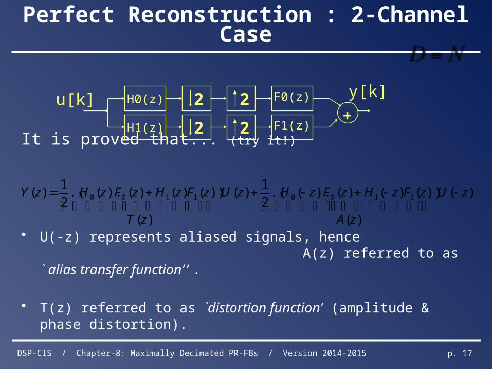
Perfect Reconstruction : 2-Channel Case
It is proved that... (try it!)
• U(-z) represents aliased signals, hence A(z) referred to as `alias transfer function’’.
• T(z) referred to as `distortion function’ (amplitude & phase distortion).
H0(z)
H1(z)
2
2
u[k] 2
2
F0(z)
F1(z)+
y[k]
)(.
)(
)}()()().(.{2
1)(.
)(
)}()()().(.{2
1)( 11001100 zU
zA
zFzHzFzHzU
zT
zFzHzFzHzY
DSP-CIS / Chapter-8: Maximally Decimated PR-FBs / Version 2014-2015 p. 18
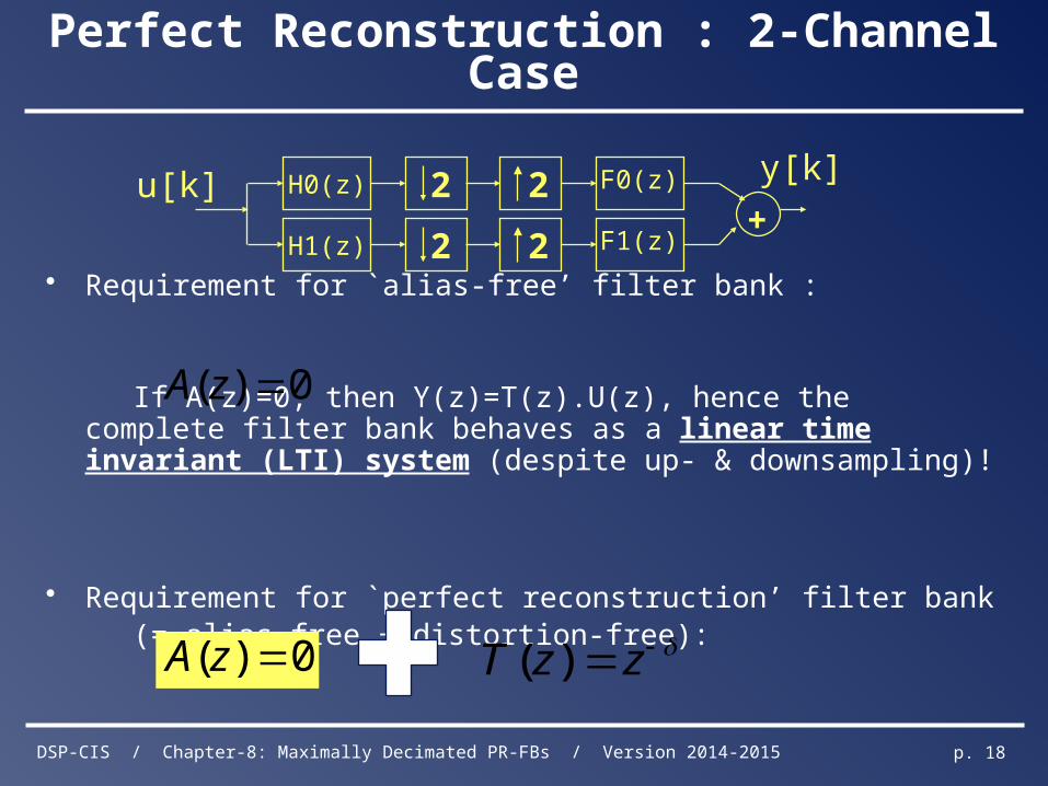
Perfect Reconstruction : 2-Channel Case
• Requirement for `alias-free’ filter bank :
If A(z)=0, then Y(z)=T(z).U(z), hence the complete filter bank behaves as a linear time invariant (LTI) system (despite up- & downsampling)!
• Requirement for `perfect reconstruction’ filter bank (= alias-free + distortion-free):
H0(z)
H1(z)
2
2
u[k] 2
2
F0(z)
F1(z)+
y[k]
0)( zA
zzT )(0)( zA
DSP-CIS / Chapter-8: Maximally Decimated PR-FBs / Version 2014-2015 p. 19
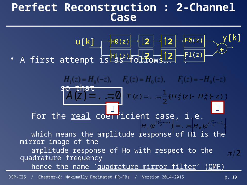
Perfect Reconstruction : 2-Channel Case
• A first attempt is as follows….. :
so that
For the real coefficient case, i.e. which means the amplitude response of H1 is the mirror image of the amplitude response of Ho with respect to the quadrature frequency hence the name `quadrature mirror filter’ (QMF)
H0(z)
H1(z)
2
2
u[k] 2
2
F0(z)
F1(z)+
y[k]
)}()({2
1...)( 2
020 zHzHzT 0...)( zA
)(...)()
2(
0
)2
(
1
jjeHeH
2
DSP-CIS / Chapter-8: Maximally Decimated PR-FBs / Version 2014-2015 p. 20
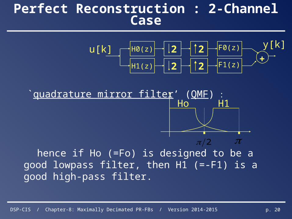
Perfect Reconstruction : 2-Channel Case
`quadrature mirror filter’ (QMF) :
hence if Ho (=Fo) is designed to be a good lowpass filter, then H1 (=-F1) is a good high-pass filter.
H0(z)
H1(z)
2
2
u[k] 2
2
F0(z)
F1(z)+
y[k]
2
Ho H1
DSP-CIS / Chapter-8: Maximally Decimated PR-FBs / Version 2014-2015 p. 21
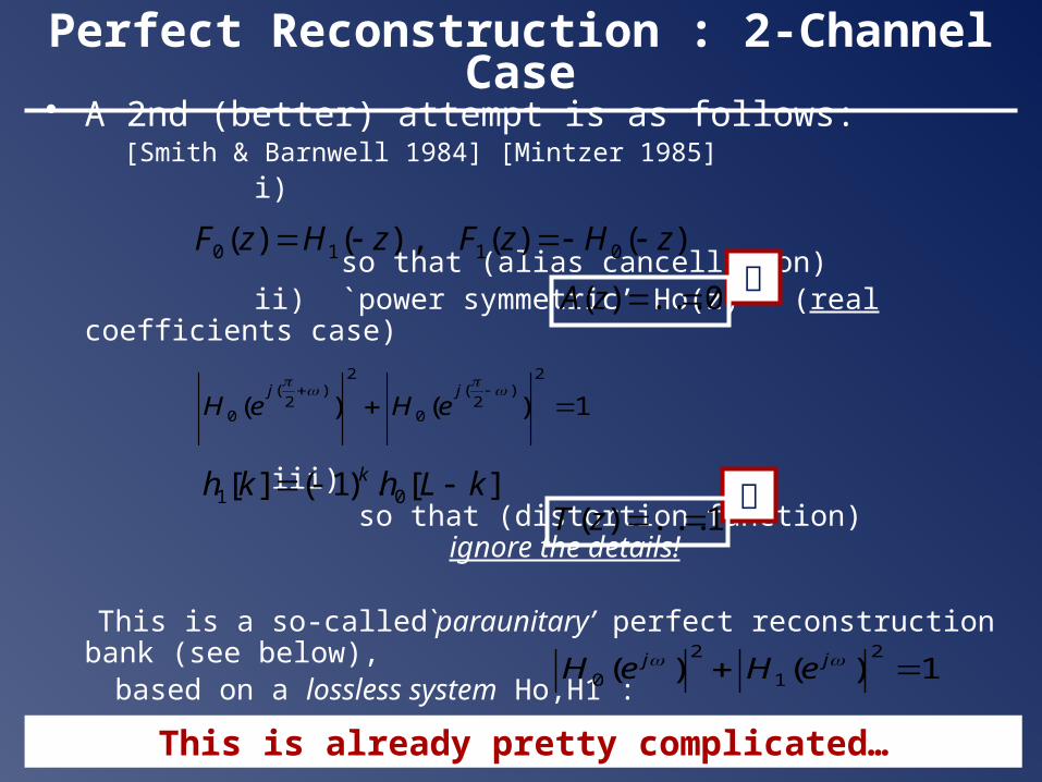
Perfect Reconstruction : 2-Channel Case
• A 2nd (better) attempt is as follows: [Smith & Barnwell 1984] [Mintzer 1985]
i)
so that (alias cancellation) ii) `power symmetric’ Ho(z) (real coefficients case)
iii) so that (distortion function) ignore the details!
This is a so-called`paraunitary’ perfect reconstruction bank (see below), based on a lossless system Ho,H1 :
1)()(2
1
2
0 jj eHeH
This is already pretty complicated…
)()( ),()( 0110 zHzFzHzF
1...)( zT
0...)( zA
1)()(
2)
2(
0
2)
2(
0
jjeHeH
][.)1(][ 01 kLhkh k
DSP-CIS / Chapter-8: Maximally Decimated PR-FBs / Version 2014-2015 p. 22
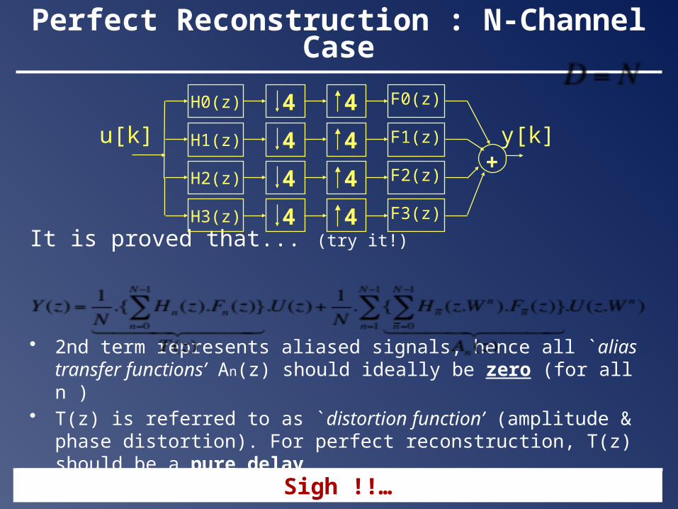
Perfect Reconstruction : N-Channel Case
It is proved that... (try it!)
• 2nd term represents aliased signals, hence all `alias transfer functions’ An(z) should ideally be zero (for all n )
• T(z) is referred to as `distortion function’ (amplitude & phase distortion). For perfect reconstruction, T(z) should be a pure delay
H2(z)
H3(z)
4
4
4
4
F2(z)
F3(z)
y[k]
H0(z)
H1(z)
4
4u[k]
4
4
F0(z)
F1(z)
+
Sigh !!…
DSP-CIS / Chapter-8: Maximally Decimated PR-FBs / Version 2014-2015 p. 23
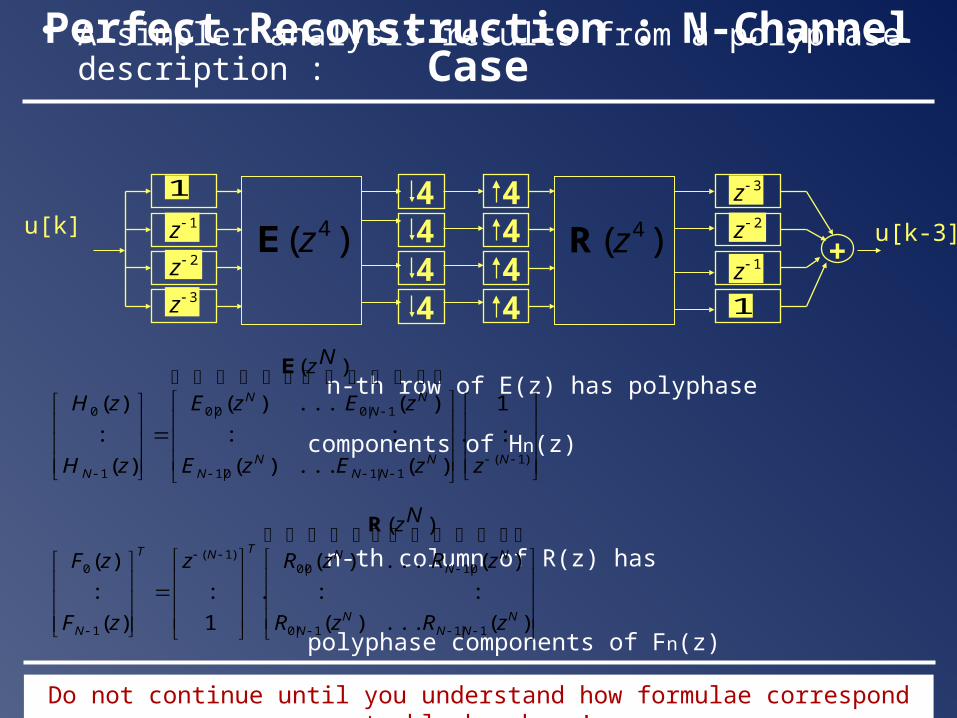
Perfect Reconstruction : N-Channel Case
• A simpler analysis results from a polyphase description :
n-th row of E(z) has polyphase components of Hn(z)
n-th column of R(z) has
polyphase components of Fn(z)
4444
+u[k-3]
1z
2z
3z
1
1z2z3z
1
u[k] 444
4
)( 4zE )( 4zR
)1(
1|10|1
1|00|0
1
0
:
1
.
)(
)(...)(
::
)(...)(
)(
:
)(
NNNN
NN
NN
N
N z
Nz
zEzE
zEzE
zH
zH E
)(
)(...)(
::
)(...)(
.
1
:
)(
:
)(
1|11|0
0|10|0)1(
1
0
Nz
zRzR
zRzRz
zF
zF
NNN
NN
NN
NTNT
N
R
Do not continue until you understand how formulae correspond to block scheme!
DSP-CIS / Chapter-8: Maximally Decimated PR-FBs / Version 2014-2015 p. 24
Perfect Reconstruction : N-Channel Case
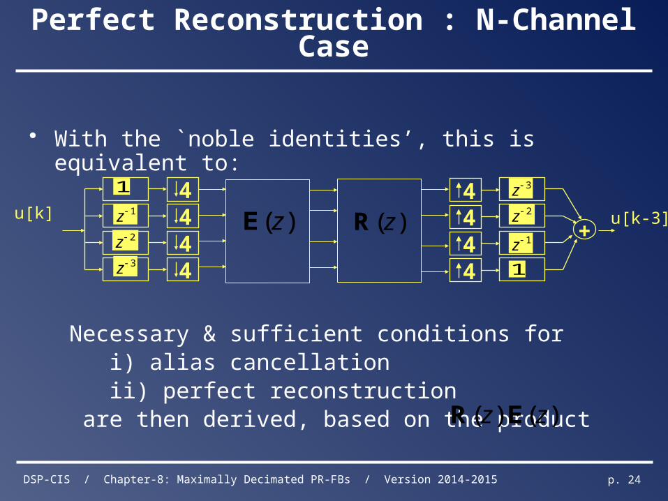
• With the `noble identities’, this is equivalent to:
Necessary & sufficient conditions for i) alias cancellation ii) perfect reconstruction are then derived, based on the product
4444
+u[k-3]
1z
2z
3z
1
1z2z3z
1
u[k] 444
4
)(zE )(zR
)().( zz ER
DSP-CIS / Chapter-8: Maximally Decimated PR-FBs / Version 2014-2015 p. 25
Perfect Reconstruction : N-Channel Case
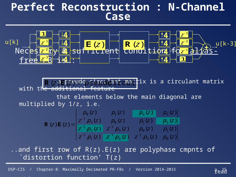
Necessary & sufficient condition for alias-free FB is…:
a pseudo-circulant matrix is a circulant matrix with the additional feature
that elements below the main diagonal are multiplied by 1/z, i.e.
..and first row of R(z).E(z) are polyphase cmpnts of `distortion function’ T(z) read on->
4444
+u[k-3]
1z
2z
3z
1
1z2z3z
1
u[k] 444
4)(zE )(zR
circulant'-`pseudo)().( zz ER
)()(.)(.)(.
)()()(.)(.
)()()()(.
)()()()(
)().(
031
21
11
1031
21
21031
3210
zpzpzzpzzpz
zpzpzpzzpz
zpzpzpzpz
zpzpzpzp
zz ER
DSP-CIS / Chapter-8: Maximally Decimated PR-FBs / Version 2014-2015 p. 26
Perfect Reconstruction : N-Channel Case
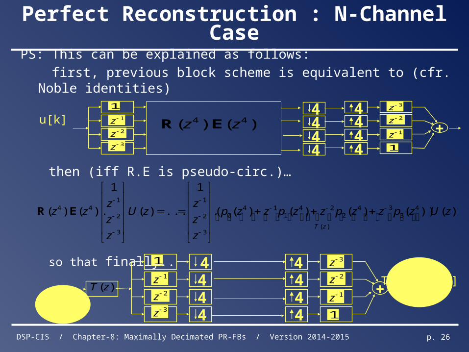
PS: This can be explained as follows:
first, previous block scheme is equivalent to (cfr. Noble identities)
then (iff R.E is pseudo-circ.)…
so that finally..
4444
+1z
2z
3z
1
1z2z3z
1
u[k] 444
4)().( 44 zz ER
)(.))()()()((.
1
...)(.
1
).().()(
43
342
241
140
3
2
1
3
2
144 zUzpzzpzzpzzp
z
z
zzU
z
z
zzz
zT
ER
44444
+1z2z3z
1
T(z)*u[k-3]444
1z
2z
3z
1u[k]
)(zT
DSP-CIS / Chapter-8: Maximally Decimated PR-FBs / Version 2014-2015 p. 27
Perfect Reconstruction : N-Channel Case
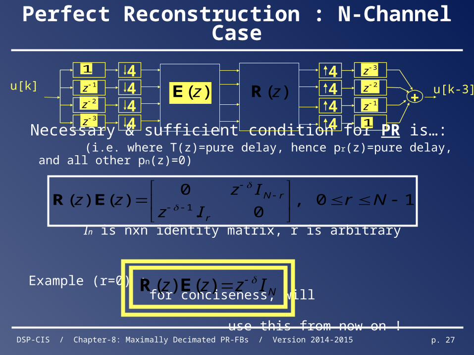
Necessary & sufficient condition for PR is…: (i.e. where T(z)=pure delay, hence pr(z)=pure delay, and all other pn(z)=0)
In is nxn identity matrix, r is arbitrary
Example (r=0) : for conciseness, will use this from now on !
4444
+u[k-3]
1z
2z
3z
1
1z2z3z
1
u[k] 444
4)(zE )(zR
10 ,0.
0)().(
1
NrIz
Izzz
r
rN
ER
NIzzz )().( ER
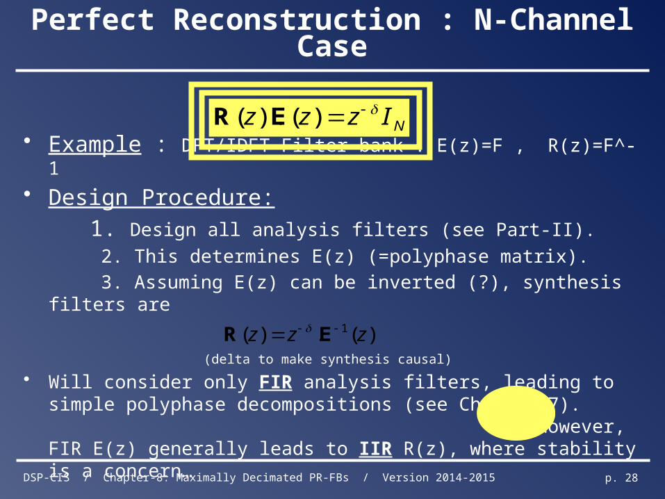
DSP-CIS / Chapter-8: Maximally Decimated PR-FBs / Version 2014-2015 p. 28
Perfect Reconstruction : N-Channel Case
• Example : DFT/IDFT Filter bank : E(z)=F , R(z)=F^-1
• Design Procedure:
1. Design all analysis filters (see Part-II).
2. This determines E(z) (=polyphase matrix).
3. Assuming E(z) can be inverted (?), synthesis filters are
(delta to make synthesis causal)
• Will consider only FIR analysis filters, leading to simple polyphase decompositions (see Chapter-7). However, FIR E(z) generally leads to IIR R(z), where stability is a concern…
)(.)( 1 zzz ER
NIzzz )().( ER
DSP-CIS / Chapter-8: Maximally Decimated PR-FBs / Version 2014-2015 p. 29
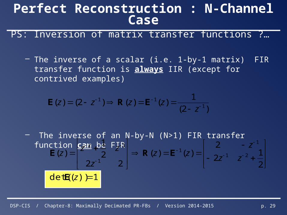
Perfect Reconstruction : N-Channel Case
PS: Inversion of matrix transfer functions ?…
– The inverse of a scalar (i.e. 1-by-1 matrix) FIR transfer function is always IIR (except for contrived examples)
– The inverse of an N-by-N (N>1) FIR transfer function can be FIR
1))(det(
2
12
2)()(
222
1)( 21
1
1
1
12
z
zz
zzz
z
zzz
E
ERE
)2(
1)()()2()(
111
zzzzz ERE
DSP-CIS / Chapter-8: Maximally Decimated PR-FBs / Version 2014-2015 p. 30
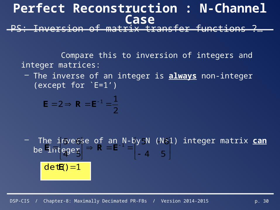
Perfect Reconstruction : N-Channel Case
PS: Inversion of matrix transfer functions ?…
Compare this to inversion of integers and integer matrices: – The inverse of an integer is always non-integer (except for `E=1’)
– The inverse of an N-by-N (N>1) integer matrix can be integer
1)det(
54
65
54
65 1
E
ERE
2
12 1 ERE
DSP-CIS / Chapter-8: Maximally Decimated PR-FBs / Version 2014-2015 p. 31
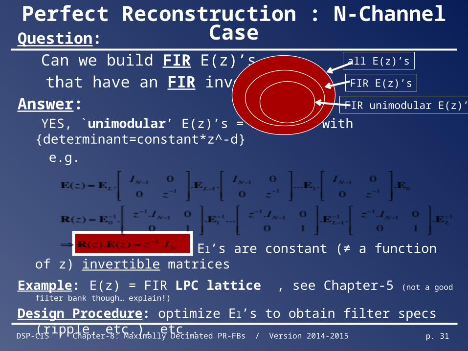
Perfect Reconstruction : N-Channel Case
Question:
Can we build FIR E(z)’s
that have an FIR inverse?
Answer: YES, `unimodular’ E(z)’s = matrices with {determinant=constant*z^-d}
e.g.
where the El’s are constant (≠ a function of z) invertible matrices
Example: E(z) = FIR LPC lattice , see Chapter-5 (not a good filter bank though… explain!)
Design Procedure: optimize El’s to obtain filter specs (ripple, etc.), etc..
all E(z)’s
FIR E(z)’s
FIR unimodular E(z)’s
DSP-CIS / Chapter-8: Maximally Decimated PR-FBs / Version 2014-2015 p. 32
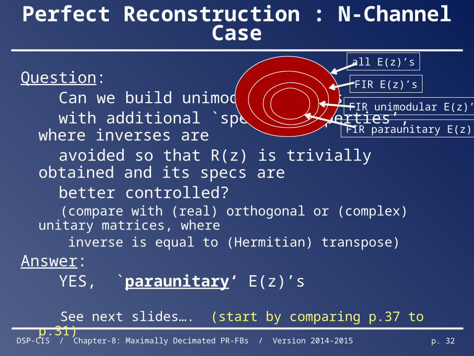
Perfect Reconstruction : N-Channel Case
Question: Can we build unimodular E(z)’s with additional `special properties’, where inverses are avoided so that R(z) is trivially obtained and its specs are better controlled? (compare with (real) orthogonal or (complex) unitary matrices, where inverse is equal to (Hermitian) transpose)
Answer: YES, `paraunitary‘ E(z)’s See next slides…. (start by comparing p.37 to p.31)
all E(z)’s
FIR E(z)’s
FIR unimodular E(z)’s
FIR paraunitary E(z)’s
DSP-CIS / Chapter-8: Maximally Decimated PR-FBs / Version 2014-2015 p. 33
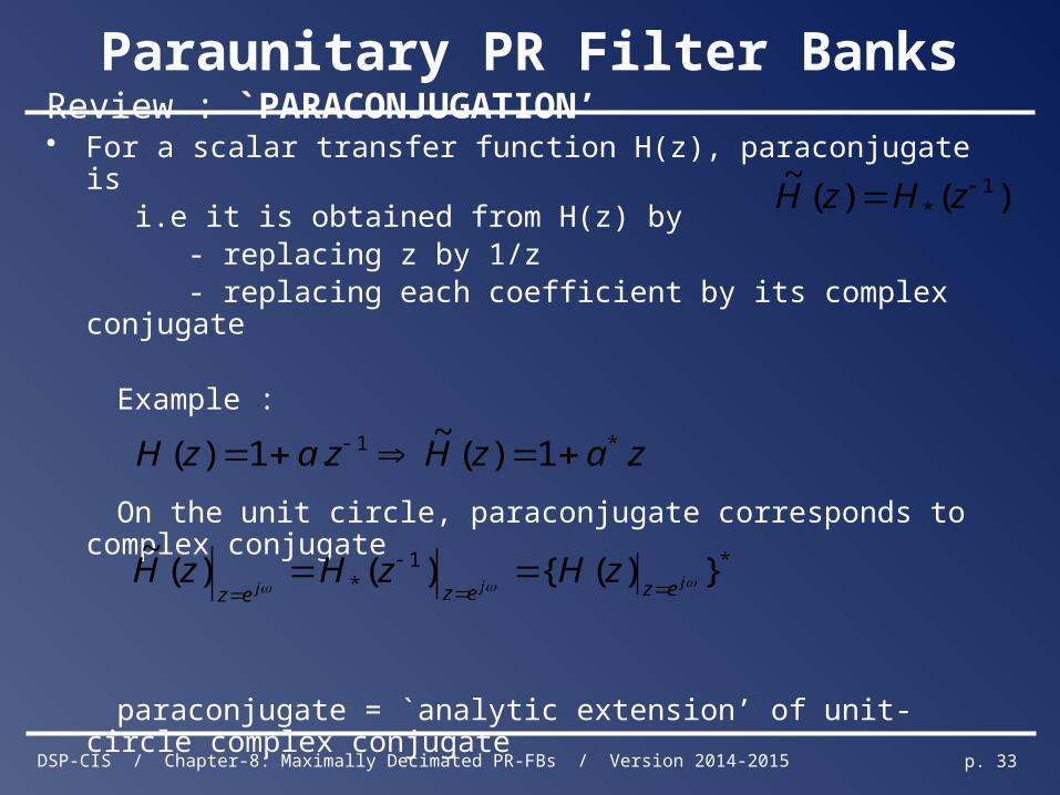
Paraunitary PR Filter Banks
Review : `PARACONJUGATION’• For a scalar transfer function H(z), paraconjugate is i.e it is obtained from H(z) by - replacing z by 1/z - replacing each coefficient by its complex conjugate
Example :
On the unit circle, paraconjugate corresponds to complex conjugate
paraconjugate = `analytic extension’ of unit-circle complex conjugate
)()(~ 1
* zHzH
zazHzazH .1)(~
.1)( *1
*1* })({)()(
~ jjj ezezez
zHzHzH
DSP-CIS / Chapter-8: Maximally Decimated PR-FBs / Version 2014-2015 p. 34
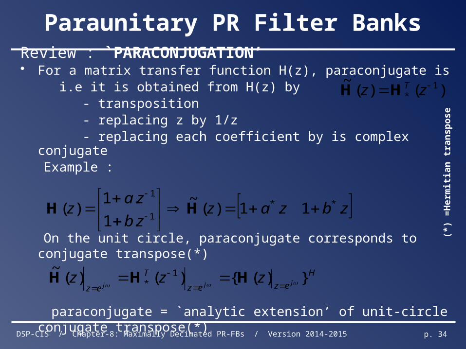
Paraunitary PR Filter Banks
Review : `PARACONJUGATION’• For a matrix transfer function H(z), paraconjugate is i.e it is obtained from H(z) by - transposition - replacing z by 1/z - replacing each coefficient by is complex conjugate Example :
On the unit circle, paraconjugate corresponds to conjugate transpose(*)
paraconjugate = `analytic extension’ of unit-circle conjugate transpose(*)
)()(~ 1
* zz THH
zbzazzb
zaz .1.1)(
~
.1
.1)( **
1
1
HH
H
ezez
T
ezjjj
zzz })({)()(~ 1
*
HHH
(*)
=H
erm
itia
n t
ran
spo
se
DSP-CIS / Chapter-8: Maximally Decimated PR-FBs / Version 2014-2015 p. 35
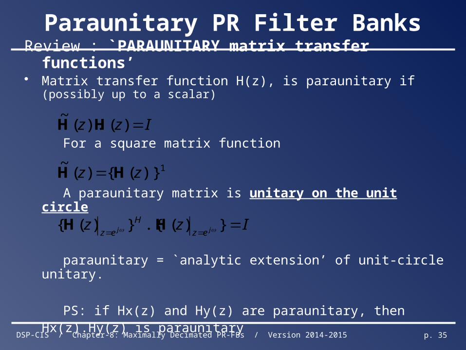
Paraunitary PR Filter Banks
Review : `PARAUNITARY matrix transfer functions’• Matrix transfer function H(z), is paraunitary if (possibly up to a scalar)
For a square matrix function
A paraunitary matrix is unitary on the unit circle
paraunitary = `analytic extension’ of unit-circle unitary.
PS: if Hx(z) and Hy(z) are paraunitary, then Hx(z).Hy(z) is paraunitary
Izz )().(~
HH
Izz jj ez
H
ez
})(.{})({ HH
1)}({)(~ zz HH
DSP-CIS / Chapter-8: Maximally Decimated PR-FBs / Version 2014-2015 p. 36
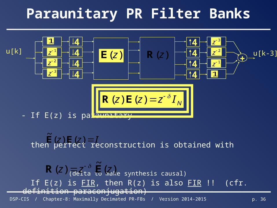
Paraunitary PR Filter Banks
- If E(z) is paraunitary
then perfect reconstruction is obtained with
(delta to make synthesis causal)
If E(z) is FIR, then R(z) is also FIR !! (cfr. definition paraconjugation)
4444
+u[k-3]
1z
2z
3z
1
1z2z3z
1
u[k] 444
4
)(zE )(zR
)(~
.)( zzz ER
Izz )().(~
EE
NIzzz )().( ER
DSP-CIS / Chapter-8: Maximally Decimated PR-FBs / Version 2014-2015 p. 37
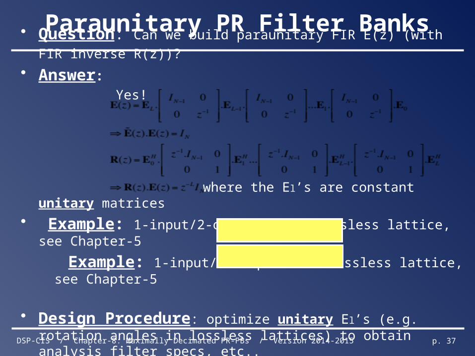
Paraunitary PR Filter Banks
• Question: Can we build paraunitary FIR E(z) (with FIR inverse R(z))? • Answer:
Yes!
where the El’s are constant unitary matrices
• Example: 1-input/2-output FIR lossless lattice, see Chapter-5
Example: 1-input/M-output FIR lossless lattice, see Chapter-5
• Design Procedure: optimize unitary El’s (e.g. rotation angles in lossless lattices) to obtain analysis filter specs, etc..
DSP-CIS / Chapter-8: Maximally Decimated PR-FBs / Version 2014-2015 p. 38
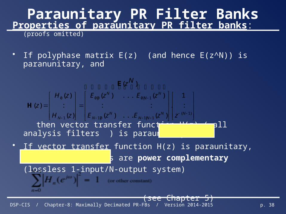
Paraunitary PR Filter Banks
Properties of paraunitary PR filter banks: (proofs omitted)
• If polyphase matrix E(z) (and hence E(z^N)) is paranunitary, and
then vector transfer function H(z) (=all analysis filters ) is paraunitary
• If vector transfer function H(z) is paraunitary, then its components are
power complementary (lossless 1-input/N-output system)
(see Chapter 5)
)1(
1|10|1
1|00|0
1
0
:
1
.
)(
)(...)(
::
)(...)(
)(
:
)(
)(NN
NNN
N
NN
N
N z
Nz
zEzE
zEzE
zH
zH
z
E
H
DSP-CIS / Chapter-8: Maximally Decimated PR-FBs / Version 2014-2015 p. 39
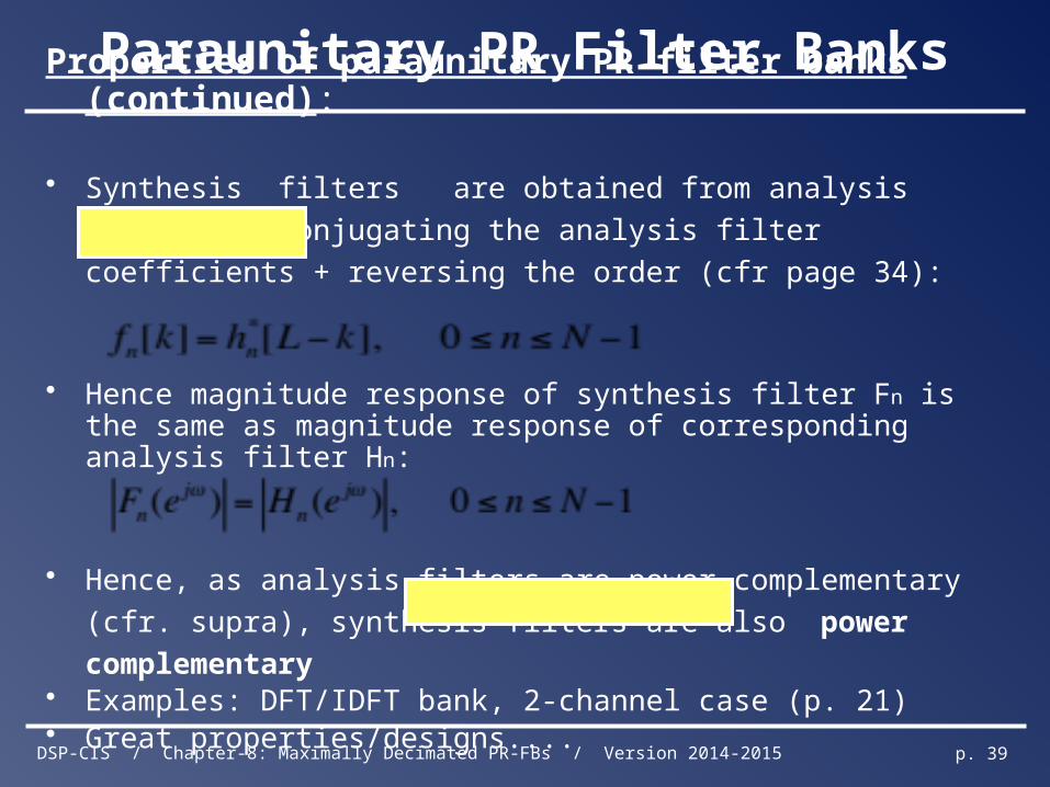
Paraunitary PR Filter Banks
Properties of paraunitary PR filter banks (continued):
• Synthesis filters are obtained from analysis filters by conjugating the
analysis filter coefficients + reversing the order (cfr page 34):
• Hence magnitude response of synthesis filter Fn is the same as magnitude response of corresponding analysis filter Hn:
• Hence, as analysis filters are power complementary (cfr. supra),
synthesis filters are also power complementary• Examples: DFT/IDFT bank, 2-channel case (p. 21)• Great properties/designs....
DSP-CIS / Chapter-8: Maximally Decimated PR-FBs / Version 2014-2015 p. 40
Conclusions
• Have derived general conditions for perfect reconstruction, based on polyphase matrices for analysis/synthesis bank
• Seen example of general PR filter bank design :
PR/FIR/Paraunitary FBs, e.g. based on FIR lossless
lattice filters• Sequel = other (better) PR structures
Chapter 9: Modulated filter banks
Chapter 10: Oversampled filter banks, etc..
• Reference: `Multirate Systems & Filter Banks’ , P.P. Vaidyanathan Prentice Hall 1993.