Embed Size (px)
Citation preview

Contents Important Safety Information ......................................................................................................2
Thanks ........................................................................................................................................3
Unpacking the DS800.................................................................................................................3
Introduction .................................................................................................................................4
Front Panel Functions ................................................................................................................5
Rear Panel Functions .................................................................................................................6
Block Diagram ............................................................................................................................7
Grounding ...................................................................................................................................8
Cooling........................................................................................................................................8
System Wiring.............................................................................................................................9
Bussing Option ...........................................................................................................................9
Specifications............................................................................................................................11
Warranty ...................................................................................................................................12
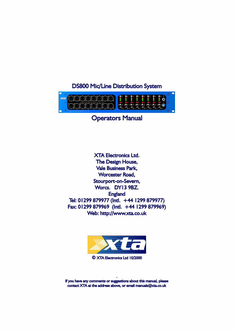
DS800 Page 2
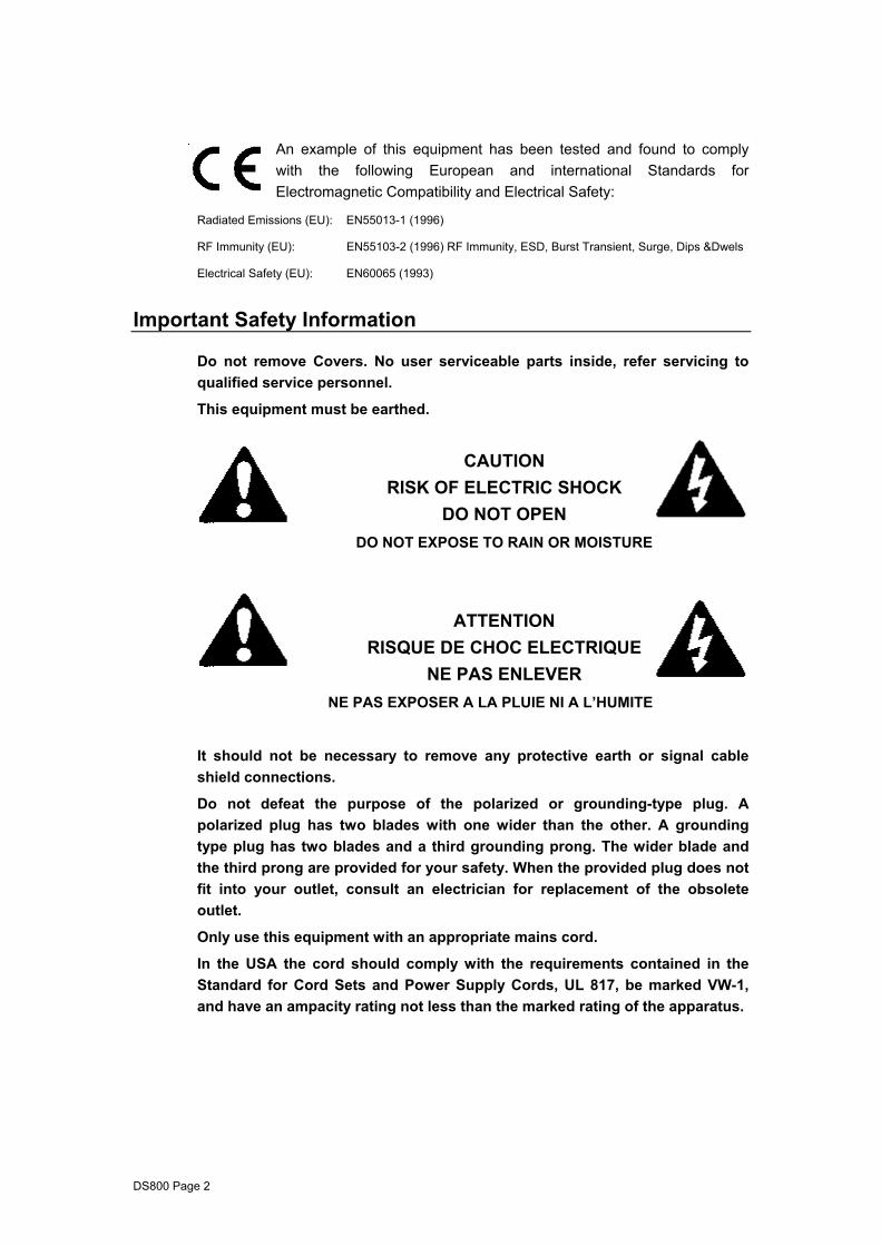
An example of this equipment has been tested and found to comply with the following European and international Standards for Electromagnetic Compatibility and Electrical Safety:
Radiated Emissions (EU): EN55013-1 (1996)
RF Immunity (EU): EN55103-2 (1996) RF Immunity, ESD, Burst Transient, Surge, Dips &Dwels
Electrical Safety (EU): EN60065 (1993)
Important Safety Information
Do not remove Covers. No user serviceable parts inside, refer servicing to qualified service personnel.
This equipment must be earthed.
CAUTION
RISK OF ELECTRIC SHOCK DO NOT OPEN
DO NOT EXPOSE TO RAIN OR MOISTURE
ATTENTION
RISQUE DE CHOC ELECTRIQUE NE PAS ENLEVER
NE PAS EXPOSER A LA PLUIE NI A L’HUMITE
It should not be necessary to remove any protective earth or signal cable shield connections.
Do not defeat the purpose of the polarized or grounding-type plug. A polarized plug has two blades with one wider than the other. A grounding type plug has two blades and a third grounding prong. The wider blade and the third prong are provided for your safety. When the provided plug does not fit into your outlet, consult an electrician for replacement of the obsolete outlet.
Only use this equipment with an appropriate mains cord.
In the USA the cord should comply with the requirements contained in the Standard for Cord Sets and Power Supply Cords, UL 817, be marked VW-1, and have an ampacity rating not less than the marked rating of the apparatus.
DS800 Page 3
Thanks
Thank you for choosing the XTA DS800 for your application. Please spare a little time to read this manual, so that you obtain the best possible performance from this unit.
All XTA products are carefully engineered for world class performance and reliability.
If you would like further information about this or any other XTA product, please contact us.
We look forward to helping you in the near future.
XTA Electronics Ltd.
Unpacking the DS800
After unpacking the unit please check carefully for damage. If damage is found, please notify the carrier concerned at once. You, the consignee, must instigate any claim. Please retain all packaging in case of future re-shipment.
DS800 Page 4
Introduction
As the need for multiple feeds has evolved, with the increase in simultaneous broadcast and recording of live concerts, so too have the performance expectations of both engineers and customers alike. The considerable signal quality 'cost', associated with traditional passive-splitter systems, due to multiple loads and long cable runs, is now widely recognised. Microphones often encounter very difficult and unpredictable loads, with impedances well below their design specifications. The result of all these parallel connections is an obvious degeneration in sound quality, and a lack of level. Although active-splitters should, and often do, solve these problems, they usually introduce more of their own. With insufficient headroom to handle line level signals or keyboards and poor noise performance, most devices simply do not provide the ideal solution. Often grounding problems are also encountered. The DS800 Mic / Line Distribution System has been carefully engineered to overcome the limitations and problems of conventional splitters and provides a new level of performance and reliability.
The XTA DS800 Mic / Line Distribution System is a high quality active distribution / splitter unit containing eight channels of processing in 2U of rack space. Each channel features one actively balanced input and a total of four outputs, two of which are individually actively balanced and normally connected to Front Of House and Stage Monitor consoles. The two remaining outputs are transformer isolated and located on the front panel of the unit. These are typically used as broadcasting or recording feeds. A maximum of 50dB gain is available via the five position Gain switch. This allows sufficient gain to be applied to low level signals, such as dynamic microphones, to avoid the poor noise performance often associated with active mic splitters. Phantom power (48VDC) is provided, and is switchable to each input by selecting 'Phantom Power' on the front panel. The DS800 is designed to reduce system grounding problems; please refer to the 'System Grounding' section further on in this manual for more information.
DS800 Page 5
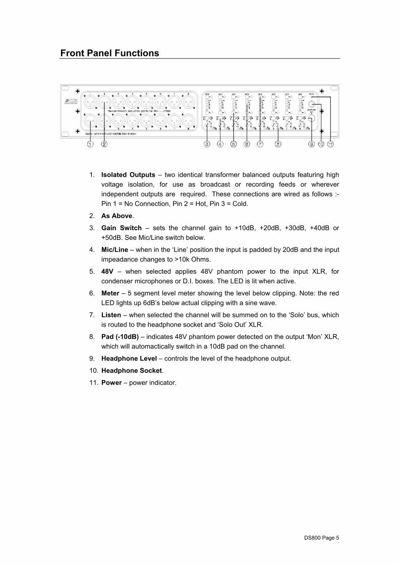
Front Panel Functions
1. Isolated Outputs – two identical transformer balanced outputs featuring high voltage isolation, for use as broadcast or recording feeds or wherever independent outputs are required. These connections are wired as follows :- Pin 1 = No Connection, Pin 2 = Hot, Pin 3 = Cold.
2. As Above.
3. Gain Switch – sets the channel gain to +10dB, +20dB, +30dB, +40dB or +50dB. See Mic/Line switch below.
4. Mic/Line – when in the ‘Line’ position the input is padded by 20dB and the input impeadance changes to >10k Ohms.
5. 48V – when selected applies 48V phantom power to the input XLR, for condenser microphones or D.I. boxes. The LED is lit when active.
6. Meter – 5 segment level meter showing the level below clipping. Note: the red LED lights up 6dB’s below actual clipping with a sine wave.
7. Listen – when selected the channel will be summed on to the ‘Solo’ bus, which is routed to the headphone socket and ‘Solo Out’ XLR.
8. Pad (-10dB) – indicates 48V phantom power detected on the output ‘Mon’ XLR, which will automactically switch in a 10dB pad on the channel.
9. Headphone Level – controls the level of the headphone output.
10. Headphone Socket.
11. Power – power indicator.
DS800 Page 6
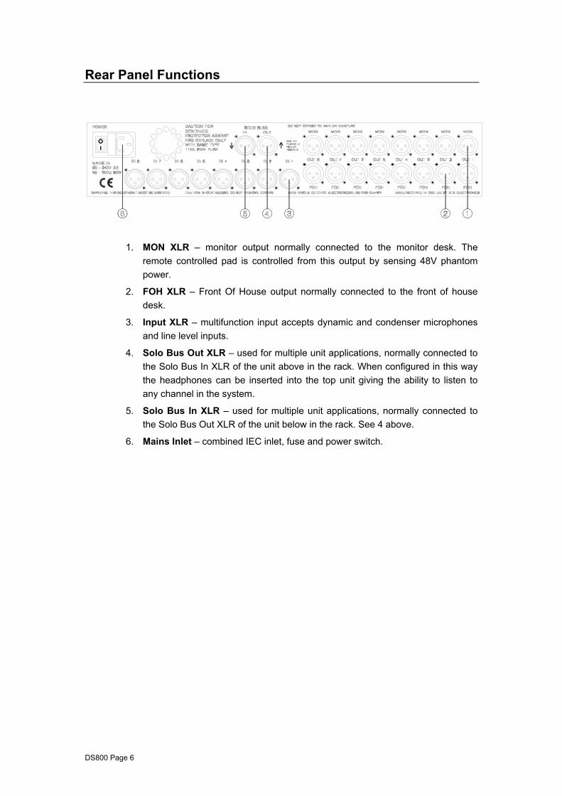
Rear Panel Functions
1. MON XLR – monitor output normally connected to the monitor desk. The remote controlled pad is controlled from this output by sensing 48V phantom power.
2. FOH XLR – Front Of House output normally connected to the front of house desk.
3. Input XLR – multifunction input accepts dynamic and condenser microphones and line level inputs.
4. Solo Bus Out XLR – used for multiple unit applications, normally connected to the Solo Bus In XLR of the unit above in the rack. When configured in this way the headphones can be inserted into the top unit giving the ability to listen to any channel in the system.
5. Solo Bus In XLR – used for multiple unit applications, normally connected to the Solo Bus Out XLR of the unit below in the rack. See 4 above.
6. Mains Inlet – combined IEC inlet, fuse and power switch.
DS800 Page 7
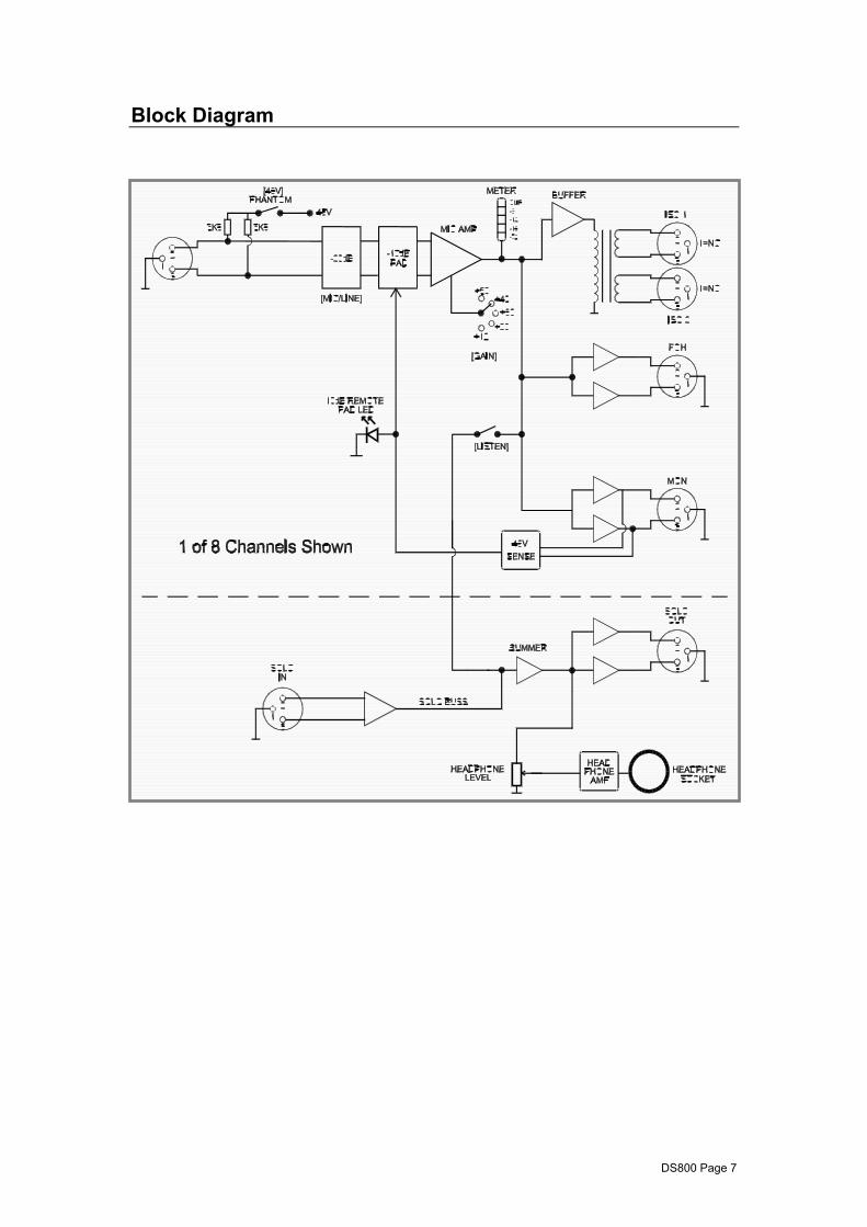
Block Diagram
DS800 Page 8
Grounding
The DS800 has a direct connection between Pin 1 of the Input XLR’s, Front of House XLR’s, Monitor XLR’s and the IEC mains inlet earth terminal. Under No circumstances should the mains ground be removed from the DS800.
The transformer isolated Output XLR’s have their Pin 1’s not connected.
To avoid ground loops and noise it is recommended that the following precautions be observed.
1. All equipment connected to the DS800 should be balanced. Any equipment that is not balanced should be interfaced via a suitable balancing system e.g. D.I. box or balancing transformer.
2. Use high quality screened cable and multi-core cable throughout the system.
3. Run all the power for back-line, monitor position, front of house, control and the DS800 from a star point (single phase).
Cooling
If you mount several DS800’s in a rack Please fan cool the rack with a minimum of one fan @ 35CFM per 6 DS800’s, blowing air into the rack (positive pressure). This will extend the life and the reliability of the units. The DS800 has been specifically designed to reside in an enclosed positive pressure rack, so that cool air forced into the back of rack migrates though the units and exits via the front panel slots.
DS800 Page 9
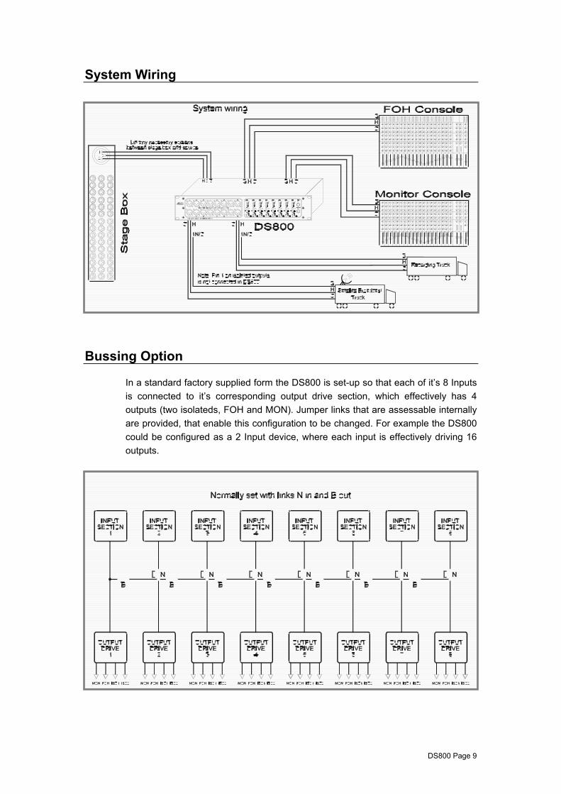
System Wiring
Bussing Option
In a standard factory supplied form the DS800 is set-up so that each of it’s 8 Inputs is connected to it’s corresponding output drive section, which effectively has 4 outputs (two isolateds, FOH and MON). Jumper links that are assessable internally are provided, that enable this configuration to be changed. For example the DS800 could be configured as a 2 Input device, where each input is effectively driving 16 outputs.
DS800 Page 10
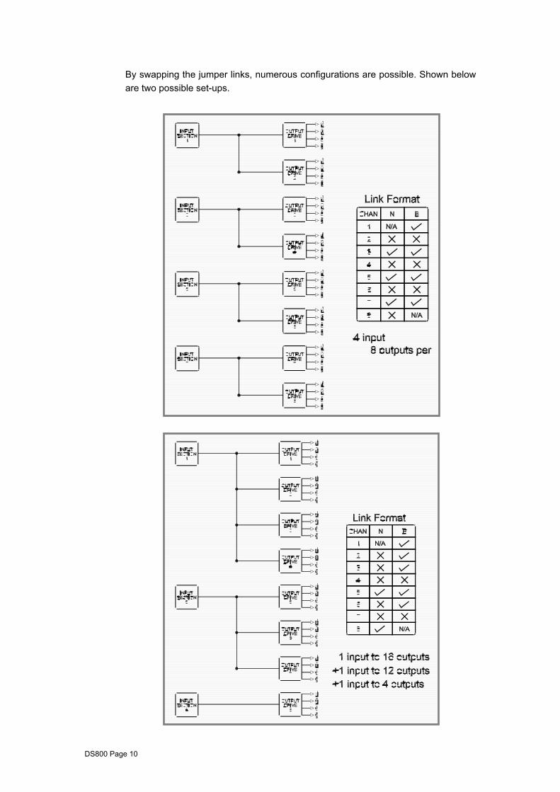
By swapping the jumper links, numerous configurations are possible. Shown below are two possible set-ups.
DS800 Page 11
Specifications Inputs 8 electronically balanced. Impedance (microphone) 2k ohms. Impedance (Line) 10k ohms. CMRR >80dB @ 1kHz. Outputs FOH 8 electronically balanced. MON 8 electronically balanced. Isolated Feeds 16 Transformer balanced. 2.5kVAC for 1 min. isolation. Source Imp < 80ohms. Min. Load 600ohm. Max. Level +20dBm into 600 ohm load. Gain. 10dB, 20dB, 30dB, 40dB or 50dB via 5 position switch. Headroom meter 5 point LED @ 0, -6, -12, -18, -30dB below clipping. Frequency Resp. ±0.5dB 20Hz - 20kHz. Equivalent Input Noise 10dB Gain: < -112dBm ( 20Hz -20kHz. Unweighted) 20dB Gain: < -117dBm 30dB Gain: < -120dBm 40dB Gain: < -120dBm Distortion < 0.01% @ 1kHz, +4dB output. Connectors Inputs 3 pin female XLR.(Pin 1 =Gnd, Pin 2 =Hot, Pin 3
=Cold.) Outputs FOH. 3 pin male XLR.(Pin 1 =Gnd, Pin 2 =Hot, Pin 3 =Cold.) Outputs MON. 3 pin male XLR.(Pin 1 =Gnd, Pin 2 =Hot, Pin 3 =Cold.) Isolated Outputs 3 pin male XLR..(Pin 1 =N/C, Pin 2 =Hot, Pin 3 =Cold.) Power 3 pin IEC. Power 80 to 250VAC @ 50/60Hz. Consumption < 40 watts. Weight 8.1kg. Net (9.5kg. Shipping) Size 3.5"(2U) * 19" * 12.2" (88 * 482 * 312mm) excluding
connectors. Options = Transformers available. Due to continuing product improvement the above specifications are subject to change.
DS800 Page 12
Warranty
This product is warranted against defects in components and workmanship only, for a period of one year from the date of shipment to the end user. During the warranty period, XTA will, at it's discretion, either repair or replace products which prove to be defective, provided that the product is returned, shipping prepaid, to an authorised XTA service facility.
Defects caused by unauthorised modifications, misuse, negligence, act of God or accident, or any use of this product that is not in accordance with the instructions provided by XTA, are not covered by this warranty.
This warranty is exclusive and no other warranty is expressed or implied. XTA is not liable for consequential damages.