Embed Size (px)
Citation preview
1/21www.burkert.com
6014
can be combined with…Type 6014
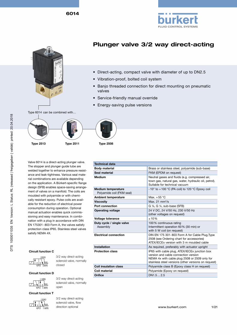
Valve 6014 is a direct-acting plunger valve. The stopper and plunger guide tube are welded together to enhance pressure resist-ance and leak-tightness. Various seal mate-rial combinations are available depending on the application. A Bürkert-specific flange design (SFB) enables space-saving arrange-ment of valves on a manifold. The coils are moulded with polyamide or with chemi-cally resistant epoxy. Pulse coils are avail-able for the reduction of electrical power consumption during operation. Optional manual actuation enables quick commis-sioning and easy maintenance. In combi-nation with a plug in accordance with DIN EN 175301 - 803 Form A, the valves satisfy protection class IP65. Stainless steel valves satisfy NEMA 4X.
• Direct-acting, compact valve with diameter of up to DN2.5
• Vibration-proof, bolted coil system
• Banjo threaded connection for direct mounting on pneumatic valves
• Service-friendly manual override
• Energy-saving pulse versions
Plunger valve 3/2 way direct-acting
Type 2513 Type 2511 Type 2508
Technical dataBody material Brass or stainless steel, polyamide (sub-base)Seal material FKM (EPDM on request)Medium Neutral gases and fluids (e.g. compressed air,
town gas, natural gas, water, hydraulic oil, petrol). Suitable for technical vacuum
Medium temperature Polyamide coil (FKM seal)
- 10° to + 100 °C (PA coil) to 120 °C Epoxy coil
Ambient temperature Max. + 55 °CViscosity Max. 21 mm2/sPort connection G ⅛, G ¼, sub-base (SFB)Operating voltage 24 V DC, 24 V/50 Hz, 230 V/50 Hz
(other voltages on request)Voltage tolerance ± 10 %Duty cycle / single valve Assembly
100 % continuous rating Intermittent operation 60 % (30 min) or with 5 W coil (on request)
Electrical connection
DIN EN 175 301- 803 Form A for Cable Plug,Type 2508 (see Ordering chart for accessories)ATEX/IECEx version with 3 m moulded cable
Installation As required, preferably with actuator uprightProtection class IP65 with cable plug, ATEX/IECEx junction box
version and cable connection versionNEMA 4x with cable plug 2508 or 2509 only for stainless steel versions (other versions on request)
Coil insulation class Polyamide class B (Epoxy class H on request)Coil material Polyamide (Epoxy on request)Orifice DN1.5 … 2.5
3/2 way direct-acting solenoid valve, normally closed
3/2 way direct-acting solenoid valve, normally open
2(A)
1(P) 3(R)
2(B)
1(P) 3(R)
3/2 way direct-acting solenoid valve, flowdirection optional
2(A)
1(P) 3(R)
Circuit function C
Circuit function D
Circuit function T
6014
2/21
Response times [ms]: Measured at valve outlet at 6 bar and + 20 ºC. Opening: Pressure build-up 0 … 90 %, to Closing: Pressure relief 100 … 10 %
Orifice Power consumption[mm] Inrush AC Hold AC (hot coil) DC hot / cold coil
[VA] [VA] [W] [W]
1.5 … 2.5 24 17 8 8 / 9
Technical data
Power consumption Response times
Orifice
[mm]
Response times AC and DC
Opening [ms] Closing [ms]
1.5 10 … 15 15 … 20
2.0 10 … 15 15 … 20
2.5 15 … 20 10 … 22
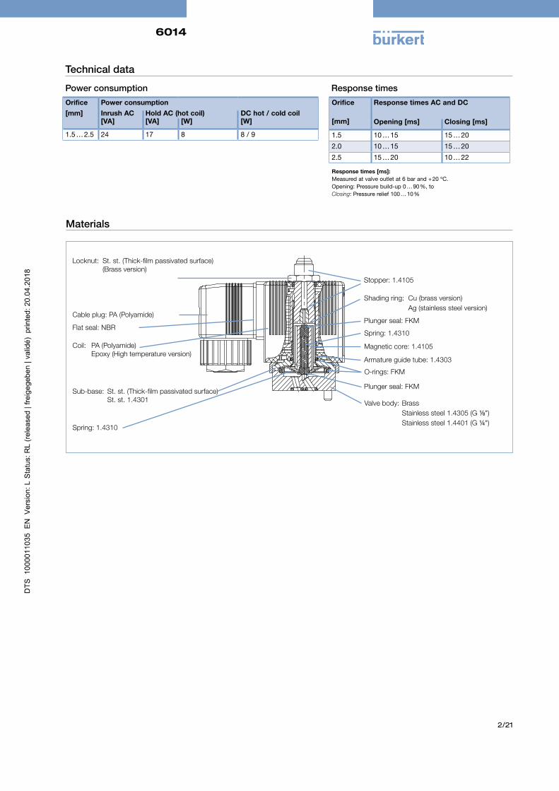
Materials
Valve body: Brass Stainless steel 1.4305 (G ⅛") Stainless steel 1.4401 (G ¼")
Plunger seal: FKM
O-rings: FKM
Armature guide tube: 1.4303
Magnetic core: 1.4105
Spring: 1.4310
Cable plug: PA (Polyamide)
Flat seal: NBR
Locknut: St. st. (Thick-film passivated surface) (Brass version)
Coil: PA (Polyamide) Epoxy (High temperature version)
Stopper: 1.4105
Shading ring: Cu (brass version) Ag (stainless steel version)
Plunger seal: FKM
Sub-base: St. st. (Thick-film passivated surface) St. st. 1.4301
Spring: 1.4310
6014
3/21
F 29
41W
S
E
24
24
Sub-base version (SFB)
B 32.6
15
15
27
8
9
18
A
32 35
G1/8 10 12
11.
2 4
1 5
.4
C
4x4x8 deep
24
M4
5.6
C
3.
7
6.3
24
32
7
**
****
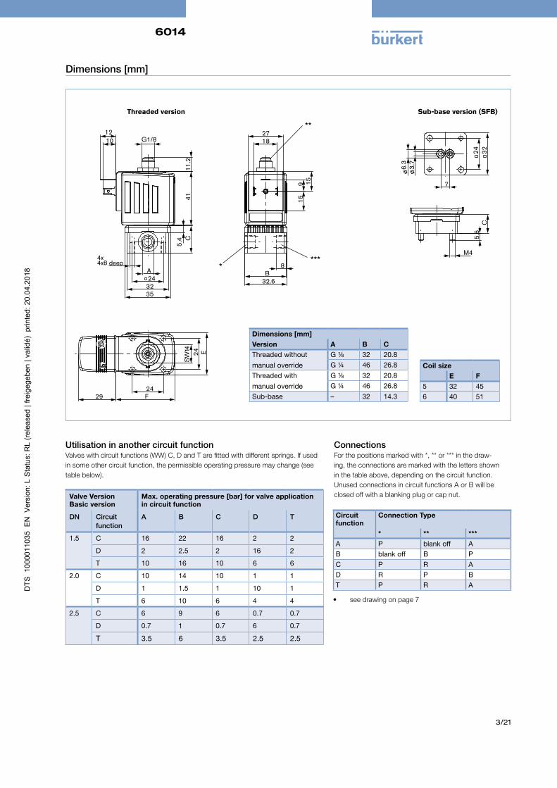
Threaded version
Dimensions [mm]
Dimensions [mm]Version A B CThreaded without manual override
G ⅛ 32 20.8G ¼ 46 26.8
Threaded with manual override
G ⅛ 32 20.8G ¼ 46 26.8
Sub-base – 32 14.3
Coil sizeE F
5 32 456 40 51
Valve VersionBasic version
Max. operating pressure [bar] for valve application in circuit function
DN Circuit function
A B C D T
1.5 C 16 22 16 2 2
D 2 2.5 2 16 2
T 10 16 10 6 6
2.0 C 10 14 10 1 1
D 1 1.5 1 10 1
T 6 10 6 4 4
2.5 C 6 9 6 0.7 0.7
D 0.7 1 0.7 6 0.7
T 3.5 6 3.5 2.5 2.5
Utilisation in another circuit functionValves with circuit functions (WW) C, D and T are fitted with different springs. If used in some other circuit function, the permissible operating pressure may change (see table below).
Circuit function
Connection Type
* ** ***A P blank off AB blank off B PC P R AD R P BT P R A
ConnectionsFor the positions marked with *, ** or *** in the draw-ing, the connections are marked with the letters shown in the table above, depending on the circuit function. Unused connections in circuit functions A or B will be closed off with a blanking plug or cap nut.
• see drawing on page 7
6014
4/21
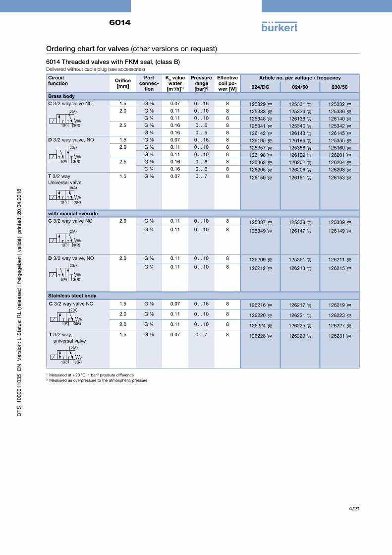
Ordering chart for valves (other versions on request)
6014 Threaded valves with FKM seal, (class B) Delivered without cable plug (see accessories)
Circuit function Orifice
[mm]
Port connec-
tion
KV value water
[m3/h]1)
Pressurerange [bar]2)
Effective coil po-wer [W]
Article no. per voltage / frequency
024/DC 024/50 230/50
Brass bodyC 3/2 way valve NC
2(A)
1(P) 3(R)
1.5 G ⅛ 0.07 0 … 16 8 125329 125331 125332 2.0 G ⅛ 0.11 0 … 10 8 125333 125334 125336
G ¼ 0.11 0 … 10 8 125348 126138 126140 2.5 G ⅛ 0.16 0 … 6 8 125341 125340 125342
G ¼ 0.16 0 … 6 8 126142 126143 126145 D 3/2 way valve, NO
2(B)
1(P) 3(R)
1.5 G ⅛ 0.07 0 … 16 8 126195 126196 125355 2.0 G ⅛ 0.11 0 … 10 8 125357 125358 125360
G ¼ 0.11 0 … 10 8 126198 126199 126201 2.5 G ⅛ 0.16 0 … 6 8 125363 126202 126204
G ¼ 0.16 0 … 6 8 126205 126206 126208 T 3/2 way Universal valve
2(A)
1(P) 3(R)
1.5 G ⅛ 0.07 0 … 7 8 126150 126151 126153
with manual overrideC 3/2 way valve NC
2(A)
1(P) 3(R)
2.0 G ⅛ 0.11 0 … 10 8 125337 125338 125339 G ¼ 0.11 0 … 10 8 125349 126147 126149
D 3/2 way valve, NO2(B)
1(P) 3(R)
2.0 G ⅛ 0.11 0 … 10 8 126209 125361 126211 G ¼ 0.11 0 … 10 8 126212 126213 126215
Stainless steel body
C 3/2 way valve NC2(A)
1(P) 3(R)
1.5 G ⅛ 0.07 0 … 16 8 126216 126217 126219
2.0 G ⅛ 0.11 0 … 10 8 126220 126221 126223
2.0 G ¼ 0.11 0 … 10 8 126224 126225 126227
T 3/2 way, universal valve
2(A)
1(P) 3(R)
1.5 G ⅛ 0.07 0 … 7 8 126228 126229 126231
1) Measured at + 20 °C, 1 bar2) pressure difference2) Measured as overpressure to the atmospheric pressure
6014
5/21
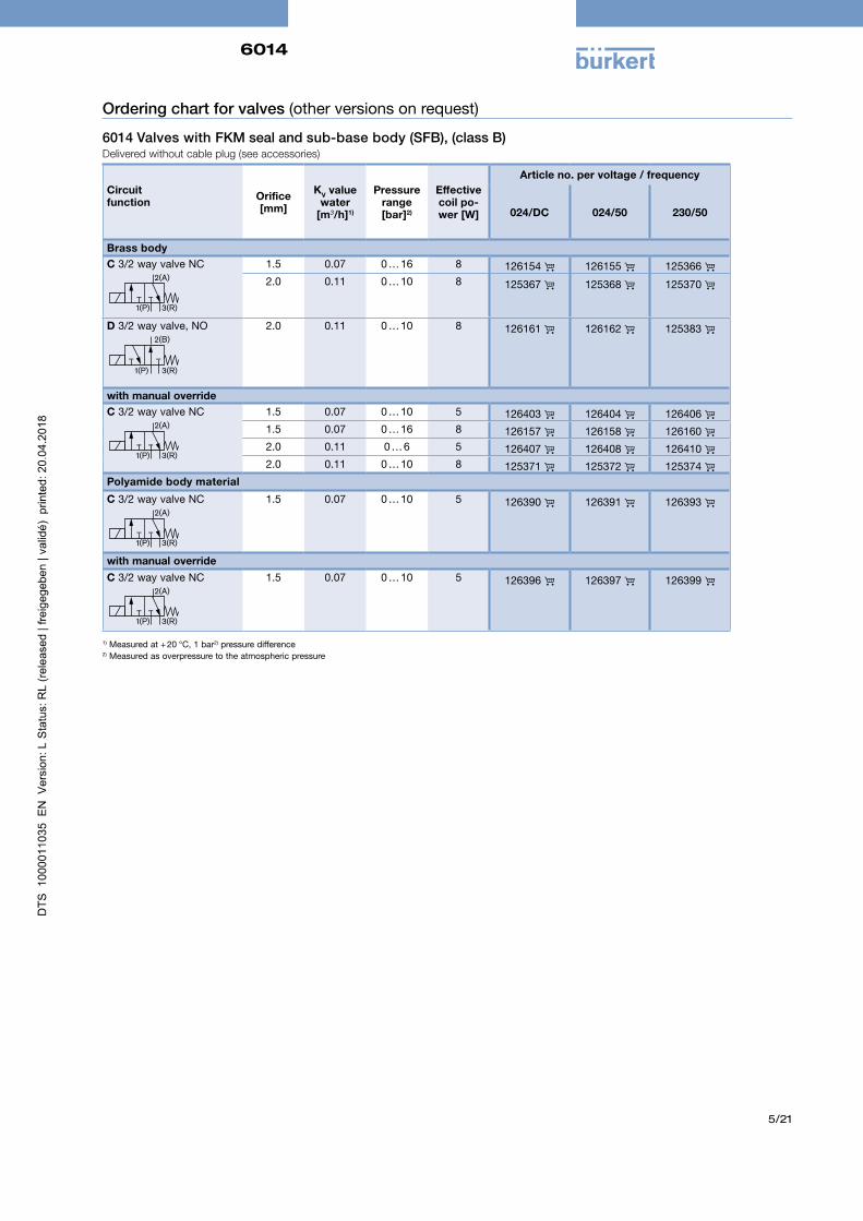
Ordering chart for valves (other versions on request)
6014 Valves with FKM seal and sub-base body (SFB), (class B) Delivered without cable plug (see accessories)
Circuit function Orifice
[mm]
KV value water
[m3/h]1)
Pressurerange [bar]2)
Effective coil po-wer [W]
Article no. per voltage / frequency
024/DC 024/50 230/50
Brass bodyC 3/2 way valve NC
2(A)
1(P) 3(R)
1.5 0.07 0 … 16 8 126154 126155 125366 2.0 0.11 0 … 10 8 125367 125368 125370
D 3/2 way valve, NO2(B)
1(P) 3(R)
2.0 0.11 0 … 10 8 126161 126162 125383
with manual overrideC 3/2 way valve NC
2(A)
1(P) 3(R)
1.5 0.07 0 … 10 5 126403 126404 126406 1.5 0.07 0 … 16 8 126157 126158 126160 2.0 0.11 0 … 6 5 126407 126408 126410 2.0 0.11 0 … 10 8 125371 125372 125374
Polyamide body material
C 3/2 way valve NC2(A)
1(P) 3(R)
1.5 0.07 0 … 10 5 126390 126391 126393
with manual overrideC 3/2 way valve NC
2(A)
1(P) 3(R)
1.5 0.07 0 … 10 5 126396 126397 126399
1) Measured at + 20 °C, 1 bar2) pressure difference2) Measured as overpressure to the atmospheric pressure
6014
6/21
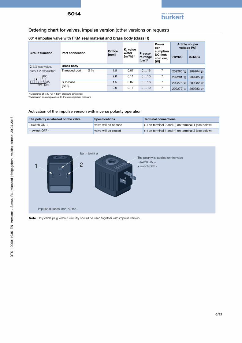
Ordering chart for valves, impulse version (other versions on request)
6014 impulse valve with FKM seal material and brass body (class H)
Circuit function Port connection Orifice [mm]
KV value water [m3/h] 1)
Power con-sumption DC (hot/cold coil) [W]
Article no. pervoltage [V/]
Pressu-re range [bar]2)
012/DC 024/DC
C 3/2 way valve, output 2 exhausted
2(A)
1(P) 3(R)
Brass bodyThreaded port G ⅛ 1.5 0.07 0 … 16 7 209280 209284
2.0 0.11 0 … 10 7 209281 209285 Sub-base{SFB)
1.5 0.07 0 … 16 7 209278 209282 2.0 0.11 0 … 10 7 209279 209283
Activation of the impulse version with inverse polarity operation
1 2The polarity is labelled on the valve- switch ON ++ switch OFF -
Earth terminal
The polarity is labelled on the valve Specifications Terminal connections
- switch ON + valve will be opened (+) on terminal 2 and (-) on terminal 1 (see below)
+ switch OFF - valve will be closed (+) on terminal 1 and (-) on terminal 2 (see below)
Impulse duration, min. 50 ms.
Note: Only cable plug without circuitry should be used together with impulse version!
1) Measured at + 20 °C, 1 bar2) pressure difference2) Measured as overpressure to the atmospheric pressure
6014
7/21
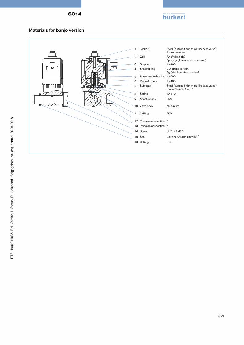
Materials for banjo version
Valve body Aluminium
Armature seal FKM
O-Ring FKM
Armature guide tube 1.4303
Magnetic core 1.4105
Spring 1.4310
Shading ring CU (brass version) Ag (stainless steel version)
Stopper 1.4105
Sub-base Steel (surface finish thick film passivated) Stainless steel 1.4301
Coil PA (Polyamide) Epoxy (high temperature version)
Locknut Steel (surface finish thick film passivated) (Brass version)
1
2
3
4
5
6
7
8
9
10
11
12
13
14
15
16
Pressure connection P
Pressure connection A
Screw CuZn / 1.4301
Seal Usit ring (Aluminium/NBR )
O-Ring NBR
6014
8/21
32 bei 2 W40 bei 8 W
G1/4
L
G
M
SW19A
A
G1/8
45 bei 2 W51 bei 8 W
10
45
31
11,
7
5
5,4
P
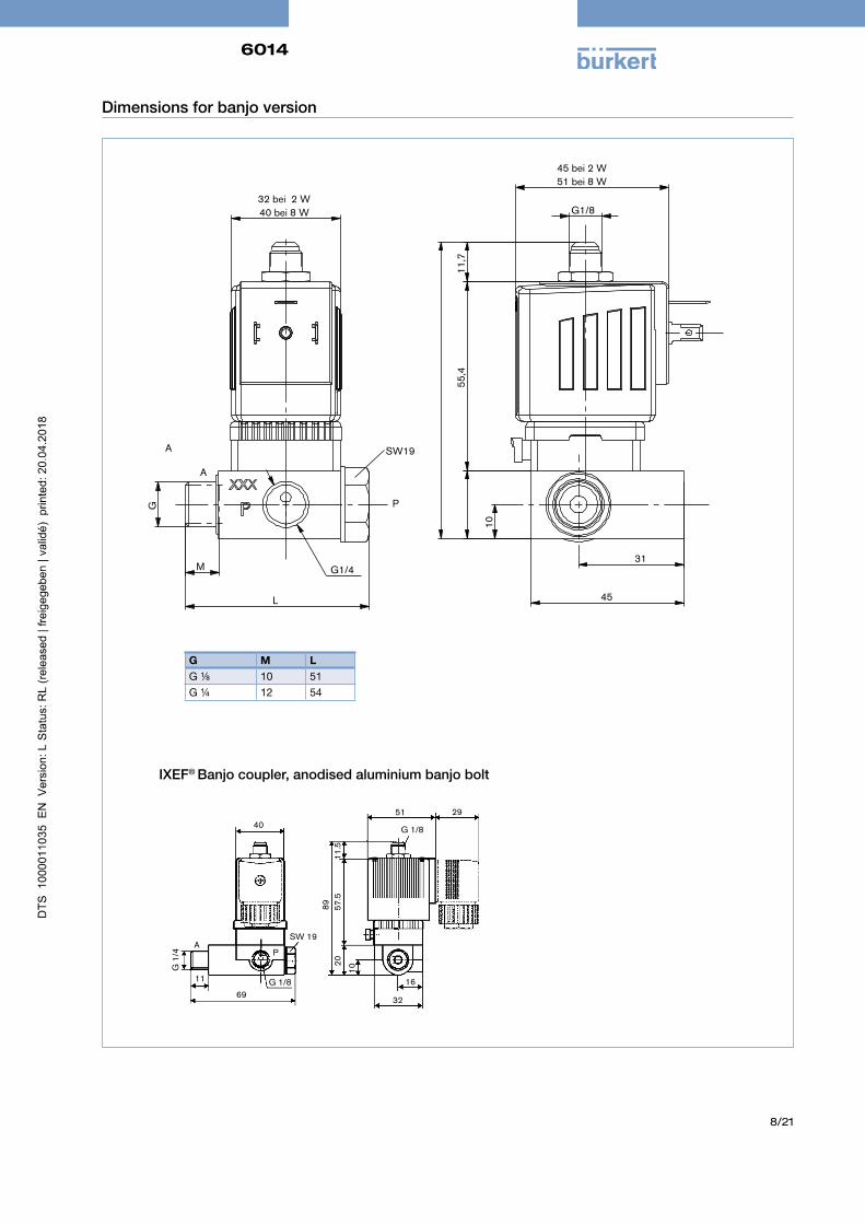
Dimensions for banjo version
G M LG ⅛ 10 51G ¼ 12 54
IXEF® Banjo coupler, anodised aluminium banjo bolt
69
40
G 1
/4
A
11 G 1/8
P
SW 19
89 57.
520
11.5
16
32
51 29
G 1/8
10
6014
9/21
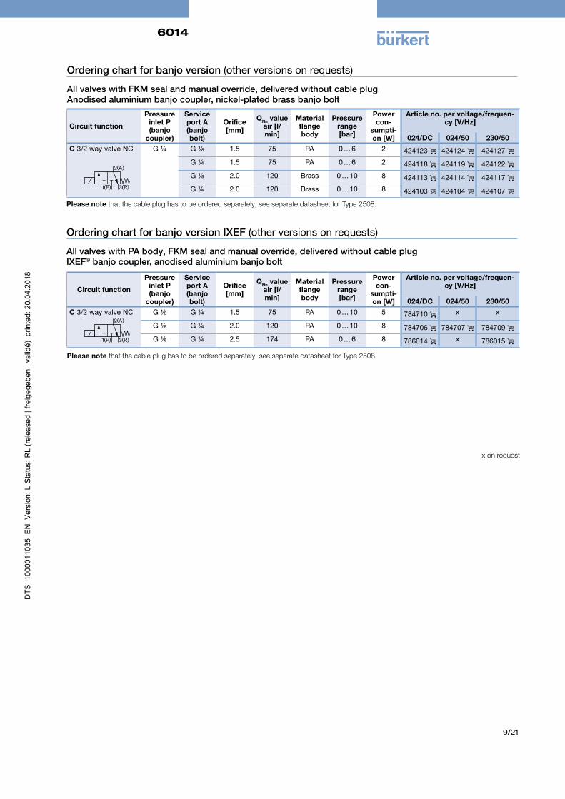
Ordering chart for banjo version (other versions on requests)
All valves with FKM seal and manual override, delivered without cable plug Anodised aluminium banjo coupler, nickel-plated brass banjo bolt
Circuit function
Pressure inlet P(banjo
coupler)
Service port A(banjo bolt)
Orifice [mm]
QNn value air [l/min]
Material flange body
Pressure range[bar]
Power con-
sumpti-on [W]
Article no. per voltage/frequen-cy [V/Hz]
024/DC 024/50 230/50C 3/2 way valve NC G ¼ G ⅛ 1.5 75 PA 0 … 6 2 424123 424124 424127
G ¼ 1.5 75 PA 0 … 6 2 424118 424119 424122 G ⅛ 2.0 120 Brass 0 … 10 8 424113 424114 424117 G ¼ 2.0 120 Brass 0 … 10 8 424103 424104 424107
2(A)
1(P) 3(R)
Please note that the cable plug has to be ordered separately, see separate datasheet for Type 2508.
Circuit function
Pressure inlet P(banjo
coupler)
Service port A(banjo bolt)
Orifice [mm]
QNn value air [l/min]
Material flange body
Pressure range[bar]
Power con-
sumpti-on [W]
Article no. per voltage/frequen-cy [V/Hz]
024/DC 024/50 230/50C 3/2 way valve NC G ⅛ G ¼ 1.5 75 PA 0 … 10 5 784710 x x
G ⅛ G ¼ 2.0 120 PA 0 … 10 8 784706 784707 784709 G ⅛ G ¼ 2.5 174 PA 0 … 6 8 786014 x 786015
Ordering chart for banjo version IXEF (other versions on requests)
All valves with PA body, FKM seal and manual override, delivered without cable plug IXEF® banjo coupler, anodised aluminium banjo bolt
2(A)
1(P) 3(R)
Please note that the cable plug has to be ordered separately, see separate datasheet for Type 2508.
x on request
6014
10/21
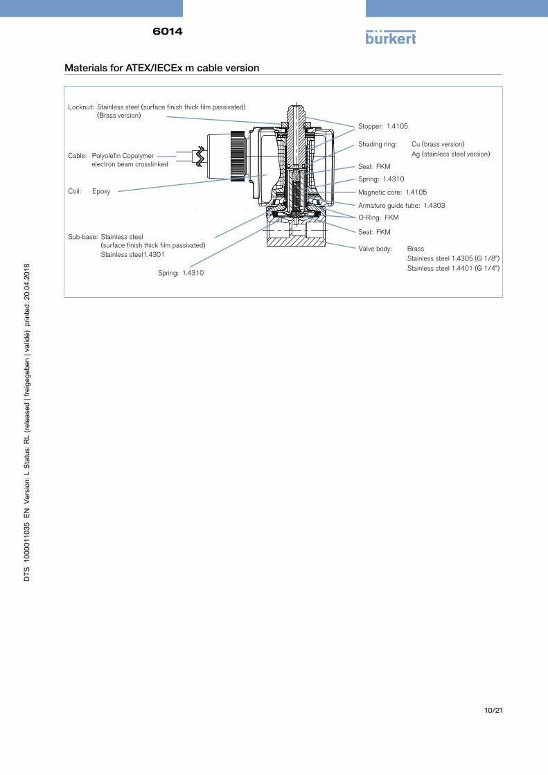
Materials for ATEX/IECEx m cable version
Valve body: Brass Stainless steel 1.4305 (G 1/8”) Stainless steel 1.4401 (G 1/4”)
Seal: FKM
O-Ring: FKM
Armature guide tube: 1.4303
Magnetic core: 1.4105
Spring: 1.4310
Locknut: Stainless steel (surface finish thick film passivated) (Brass version)
Coil:
Epoxy
Stopper: 1.4105
Shading ring: Cu (brass version) Ag (stainless steel version)
Seal: FKM
Sub-base: Stainless steel (surface finish thick film passivated)
Stainless steel1.4301
Spring: 1.4310
Cable: Polyolefin Copolymer electron beam crosslinked
6014
11/21
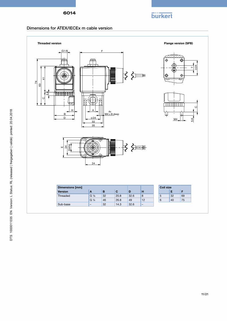
Dimensions for ATEX/IECEx m cable version
D
C
63 7
4 41
B
G1/8
5.4
H A
35 32
F
4xM4 x 8 deep
24
24
24
Flange version (SFB)
41W
S
E
C
5.6
M4
24
7
Threaded version
Dimensions [mm]Version A B C D HThreaded G ⅛ 32 20.8 32.6 8
G ¼ 46 26.8 49 12Sub-base – 32 14.3 32.6 –
Coil sizeE F
5 32 696 40 75
6014
12/21
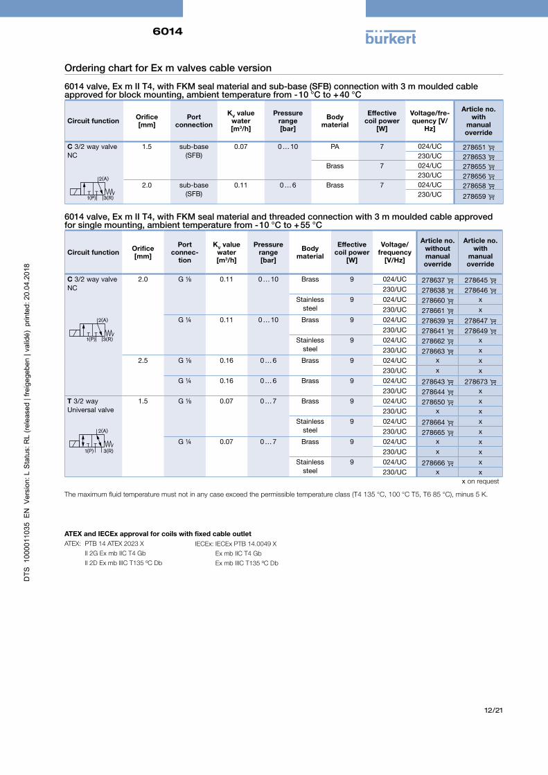
Ordering chart for Ex m valves cable version
6014 valve, Ex m II T4, with FKM seal material and sub-base (SFB) connection with 3 m moulded cable approved for block mounting, ambient temperature from - 10 °C to + 40 °C
Circuit function Orifice[mm]
Portconnection
KV value water[m3/h]
Pressure range [bar]
Body material
Effective coil power
[W]
Voltage/fre-quency [V/
Hz]
Article no.with
manual override
C 3/2 way valve NC
2(A)
1(P) 3(R)
1.5 sub-base(SFB)
0.07 0 … 10 PA 7 024/UC 278651 230/UC 278653
Brass 7 024/UC 278655 230/UC 278656
2.0 sub-base(SFB)
0.11 0 … 6 Brass 7 024/UC 278658 230/UC 278659
6014 valve, Ex m II T4, with FKM seal material and threaded connection with 3 m moulded cable approved for single mounting, ambient temperature from - 10 °C to + 55 °C
Circuit function Orifice[mm]
Portconnec-
tion
KV value water[m3/h]
Pressure range [bar]
Body material
Effective coil power
[W]
Voltage/frequency
[V/Hz]
Article no.without manual override
Article no.with
manual override
C 3/2 way valve NC
2(A)
1(P) 3(R)
2.0 G ⅛ 0.11 0 … 10 Brass 9 024/UC 278637 278645 230/UC 278638 278646
Stainless steel
9 024/UC 278660 x230/UC 278661 x
G ¼ 0.11 0 … 10 Brass 9 024/UC 278639 278647 230/UC 278641 278649
Stainless steel
9 024/UC 278662 x230/UC 278663 x
2.5 G ⅛ 0.16 0 … 6 Brass 9 024/UC x x230/UC x x
G ¼ 0.16 0 … 6 Brass 9 024/UC 278643 278673 230/UC 278644 x
T 3/2 way Universal valve
2(A)
1(P) 3(R)
1.5 G ⅛ 0.07 0 … 7 Brass 9 024/UC 278650 x230/UC x x
Stainless steel
9 024/UC 278664 x230/UC 278665 x
G ¼ 0.07 0 … 7 Brass 9 024/UC x x230/UC x x
Stainless steel
9 024/UC 278666 x230/UC x x
The maximum fluid temperature must not in any case exceed the permissible temperature class (T4 135 °C, 100 °C T5, T6 85 °C), minus 5 K.
x on request
IECEx: IECEx PTB 14.0049 X Ex mb IIC T4 Gb Ex mb IIIC T135 ºC Db
ATEX and IECEx approval for coils with fixed cable outletATEX: PTB 14 ATEX 2023 X II 2G Ex mb IIC T4 Gb II 2D Ex mb IIIC T135 ºC Db
6014
13/21
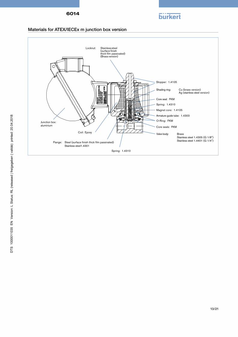
Materials for ATEX/IECEx m junction box version
Valve body: Brass
Stainless steel 1.4305 (G 1/8”)
Stainless steel 1.4401 (G 1/4”)
Core seals: FKM
O-Ring: FKM
Armature guide tube: 1.4303
Magnet core: 1.4105
Spring: 1.4310
Coil:
Epoxy
Stopper: 1.4105
Shading ring: Cu (brass version)
Ag (stainless steel version)
Core seal: FKM
Flange: Steel (surface finish thick film passivated)
Stainless steel1.4301
Spring: 1.4310
Junction box: aluminium
Locknut: Stainless steel (surface finish thick film passivated) (Brass version)
6014
14/21
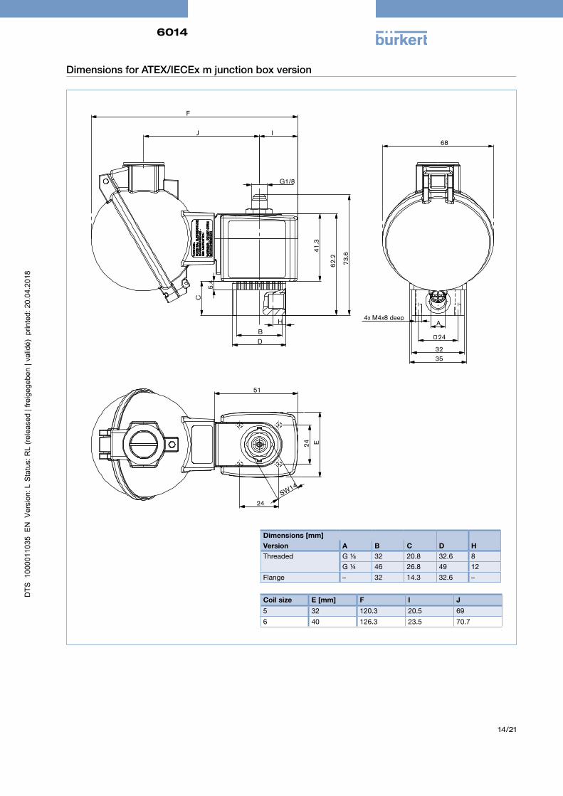
Dimensions for ATEX/IECEx m junction box version
Dimensions [mm]Version A B C D HThreaded G ⅛ 32 20.8 32.6 8
G ¼ 46 26.8 49 12Flange – 32 14.3 32.6 –
J I
B D
5.4
C
41.
3
62.
2
73.
6
G1/8
F
H A
32 35
68
4x M4x8 deep
24
SW14
51
E
24
24
Coil size E [mm] F I J
5 32 120.3 20.5 696 40 126.3 23.5 70.7
6014
15/21
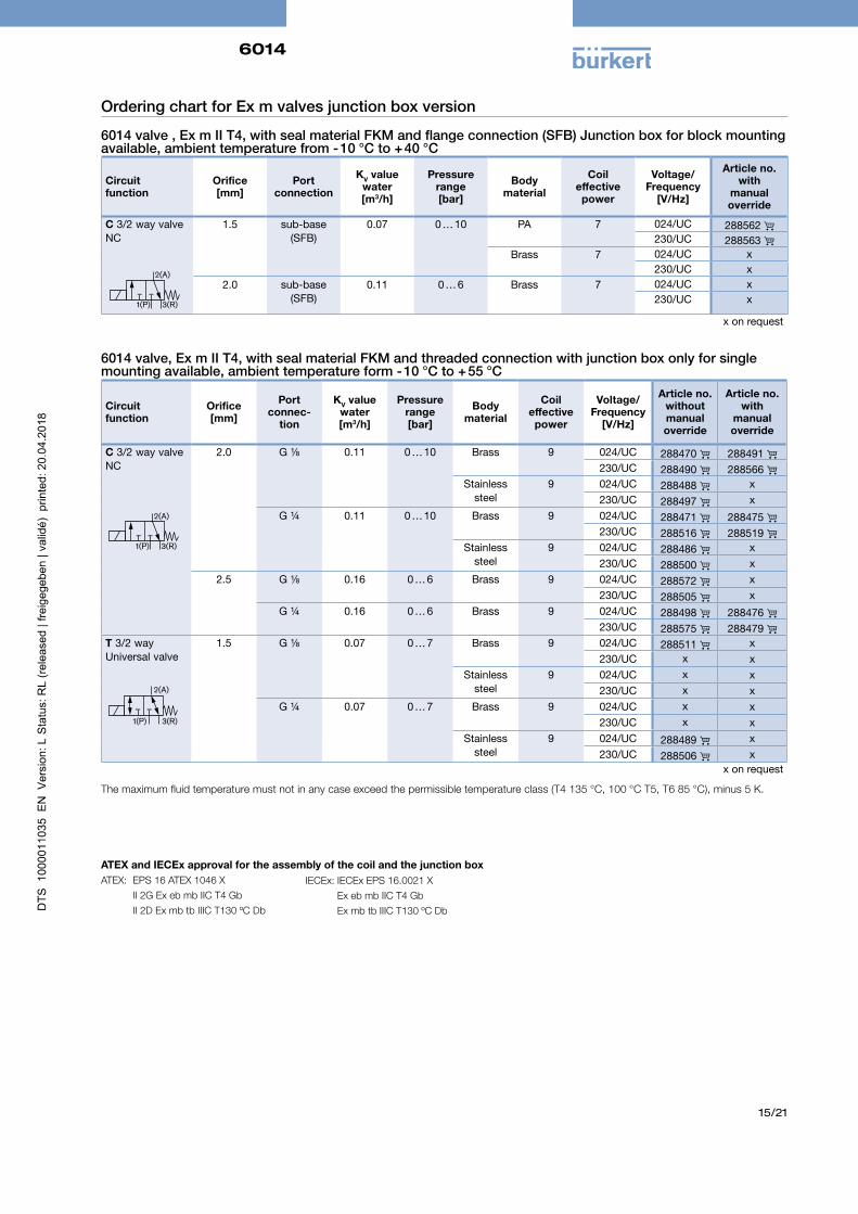
Ordering chart for Ex m valves junction box version
6014 valve , Ex m II T4, with seal material FKM and flange connection (SFB) Junction box for block mounting available, ambient temperature from - 10 °C to + 40 °C
Circuit function
Orifice [mm]
Port connection
KV value water[m3/h]
Pressure range [bar]
Body material
Coil effective power
Voltage/ Frequency
[V/Hz]
Article no. with
manual override
C 3/2 way valve NC
2(A)
1(P) 3(R)
1.5 sub-base(SFB)
0.07 0 … 10 PA 7 024/UC 288562 230/UC 288563
Brass 7 024/UC x230/UC x
2.0 sub-base(SFB)
0.11 0 … 6 Brass 7 024/UC x230/UC x
6014 valve, Ex m II T4, with seal material FKM and threaded connection with junction box only for single mounting available, ambient temperature form - 10 °C to + 55 °C
Circuit function
Orifice [mm]
Port connec-
tion
KV value water[m3/h]
Pressure range [bar]
Body material
Coil effective power
Voltage/ Frequency
[V/Hz]
Article no. without manual override
Article no. with
manual override
C 3/2 way valve NC
2(A)
1(P) 3(R)
2.0 G ⅛ 0.11 0 … 10 Brass 9 024/UC 288470 288491 230/UC 288490 288566
Stainless steel
9 024/UC 288488 x230/UC 288497 x
G ¼ 0.11 0 … 10 Brass 9 024/UC 288471 288475 230/UC 288516 288519
Stainless steel
9 024/UC 288486 x230/UC 288500 x
2.5 G ⅛ 0.16 0 … 6 Brass 9 024/UC 288572 x230/UC 288505 x
G ¼ 0.16 0 … 6 Brass 9 024/UC 288498 288476 230/UC 288575 288479
T 3/2 way Universal valve
2(A)
1(P) 3(R)
1.5 G ⅛ 0.07 0 … 7 Brass 9 024/UC 288511 x230/UC x x
Stainless steel
9 024/UC x x230/UC x x
G ¼ 0.07 0 … 7 Brass 9 024/UC x x230/UC x x
Stainless steel
9 024/UC 288489 x230/UC 288506 x
The maximum fluid temperature must not in any case exceed the permissible temperature class (T4 135 °C, 100 °C T5, T6 85 °C), minus 5 K.
x on request
x on request
IECEx: IECEx EPS 16.0021 X Ex eb mb IIC T4 Gb Ex mb tb IIIC T130 ºC Db
ATEX and IECEx approval for the assembly of the coil and the junction boxATEX: EPS 16 ATEX 1046 X II 2G Ex eb mb IIC T4 Gb II 2D Ex mb tb IIIC T130 ºC Db
6014
16/21
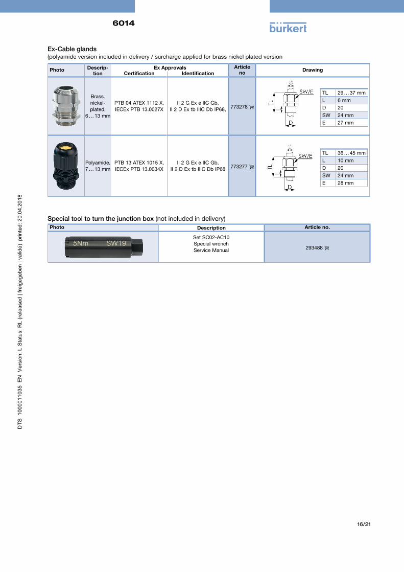
Ex-Cable glands (polyamide version included in delivery / surcharge applied for brass nickel plated version
Photo Descrip-tion
Ex Approvals Article no Drawing
Certification Identification
Brass. nickel-plated,
6 … 13 mm
PTB 04 ATEX 1112 X, IECEx PTB 13.0027X
II 2 G Ex e IIC Gb, II 2 D Ex tb IIIC Db IP68, 773278
Polyamide,7 … 13 mm
PTB 13 ATEX 1015 X, IECEx PTB 13.0034X
II 2 G Ex e IIC Gb, II 2 D Ex tb IIIC Db IP68 773277
TL 29 … 37 mmL 6 mmD 20SW 24 mmE 27 mm
TL 36 … 45 mmL 10 mmD 20SW 24 mmE 28 mm
Special tool to turn the junction box (not included in delivery)Photo Description Article no.
Set SC02-AC10Special wrenchService Manual 293488
6014
17/21
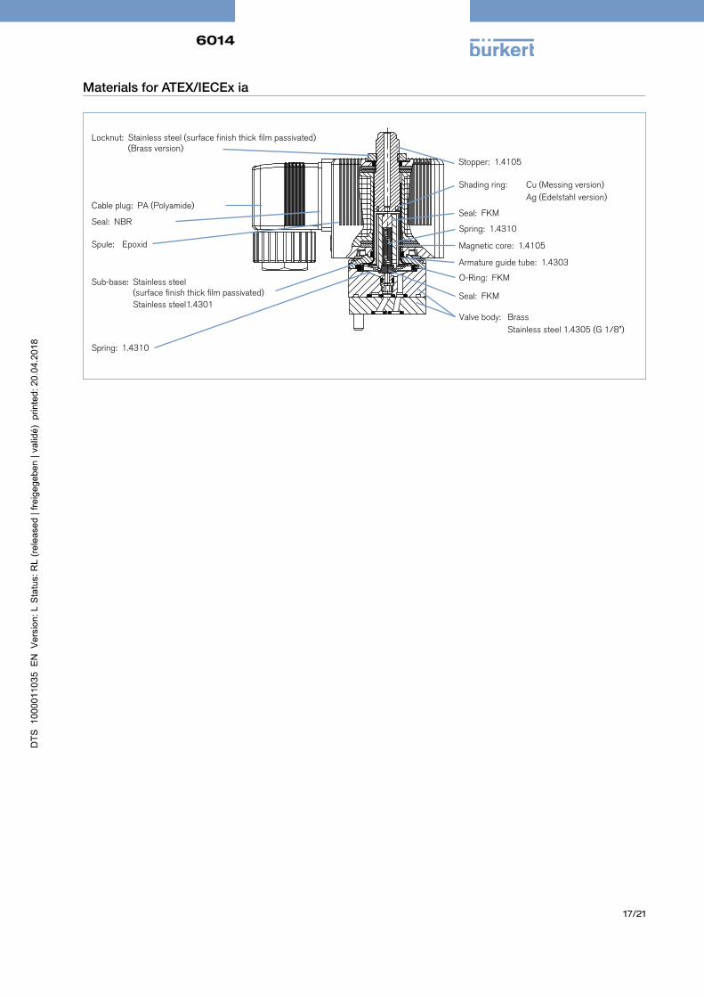
Materials for ATEX/IECEx ia
Valve body: Brass Stainless steel 1.4305 (G 1/8”)
Seal: FKM
O-Ring: FKM
Armature guide tube: 1.4303
Magnetic core: 1.4105
Spring: 1.4310
Cable plug: PA (Polyamide)
Seal: NBR
Spule:
Epoxid
Stopper: 1.4105
Shading ring: Cu (Messing version) Ag (Edelstahl version)
Seal: FKM
Spring: 1.4310
Locknut: Stainless steel (surface finish thick film passivated) (Brass version)
Sub-base: Stainless steel (surface finish thick film passivated) Stainless steel1.4301
6014
18/21
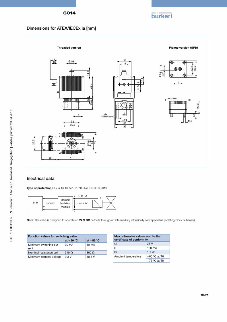
Dimensions for ATEX/IECEx ia [mm]
32 32.6
20.
8 5.4
4
1.4
11.
2
12 10 G1/8
8
27
A
32 35
18
9
14.
5 1
5.1
4xM4x8 deep
24
41W
S
40
51 29
27.
5
24
M4
6.5
23.
3
24
7
6.
3
32
3.7
Flange version (SFB)Threaded version
Electrical data
Type of protection EEx ia IIC T6 acc. to PTB-No. Ex- 96.D.2010
Note: The valve is designed to operate on 24 V DC outputs through an intermediary intrinsically safe apparatus (isolating block or barrier)..
PLCBarrier/Isolation module
24 V DC > 9.3 V DC
+≥ 30 mA+
–
Function values for switching valveat + 20 °C at + 55 °C
Minimum switching cur-rent
30 mA 30 mA
Nominal resistance coil 310 Ω 360 ΩMinimum terminal voltage 9.3 V 10.8 V
Max. allowable values acc. to thecertificate of conformityUi 28 Vli 120 mAPi 1.1 WAmbient temperature + 60 ºC at T6
+ 75 ºC at T5
6014
19/21
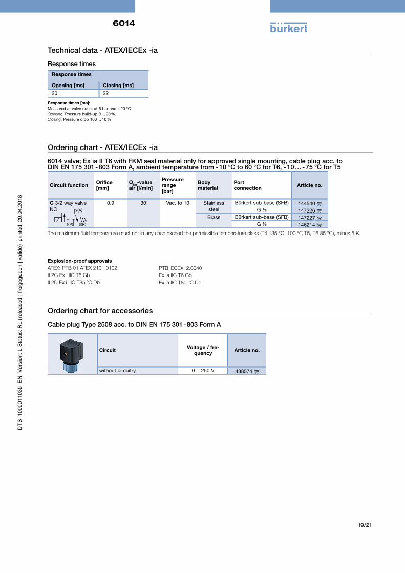
Ordering chart - ATEX/IECEx -ia
6014 valve; Ex ia II T6 with FKM seal material only for approved single mounting, cable plug acc. to DIN EN 175 301 - 803 Form A, ambient temperature from - 10 °C to 60 °C for T6, - 10 … - 75 °C for T5
Circuit function Orifice [mm]
QNn-value air [l/min]
Pressure range [bar]
Body material
Port connection Article no.
C 3/2 way valve NC
0.9 30 Vac. to 10 Stainless steel
Bürkert sub-base (SFB) 144540 G ⅛ 147226
Brass Bürkert sub-base (SFB) 147227 G ⅛ 146214
The maximum fluid temperature must not in any case exceed the permissible temperature class (T4 135 °C, 100 °C T5, T6 85 °C), minus 5 K.
Response times [ms]: Measured at valve outlet at 6 bar and + 20 ºCOpening: Pressure build-up 0 … 90 %, Closing: Pressure drop 100 … 10 %
Technical data - ATEX/IECEx -ia
Response times
Response times
Opening [ms] Closing [ms]20 22
Ordering chart for accessories
Cable plug Type 2508 acc. to DIN EN 175 301 - 803 Form A
Circuit Voltage / fre-quency Article no.
without circuitry 0 … 250 V 438574
Explosion-proof approvalsATEX: PTB 01 ATEX 2101 0102 II 2G Ex i IIC T6 GbII 2D Ex i IIIC T85 ºC Db
PTB IECEX12.0040Ex ia IIC T6 GbEx ia IIC T80 °C Db
2(A)
1(P) 3(R)
6014
20/21
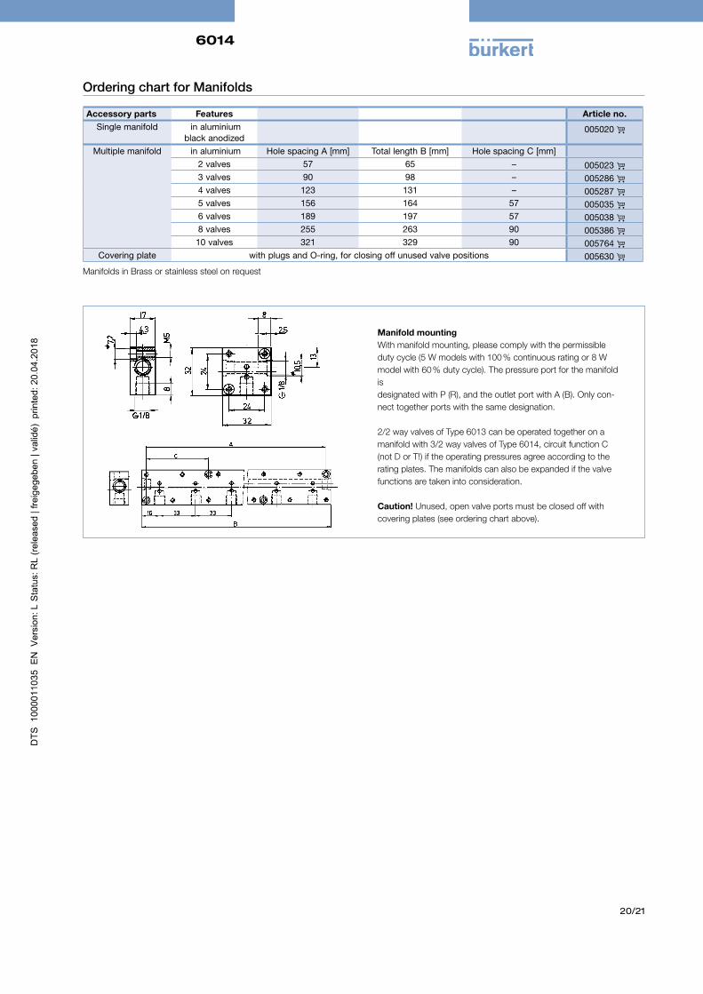
Manifold mountingWith manifold mounting, please comply with the permissible duty cycle (5 W models with 100 % continuous rating or 8 W model with 60 % duty cycle). The pressure port for the manifold is designated with P (R), and the outlet port with A (B). Only con-nect together ports with the same designation.
2/2 way valves of Type 6013 can be operated together on a manifold with 3/2 way valves of Type 6014, circuit function C (not D or T!) if the operating pressures agree according to the rating plates. The manifolds can also be expanded if the valve functions are taken into consideration.
Caution! Unused, open valve ports must be closed off with covering plates (see ordering chart above).
Ordering chart for Manifolds
Accessory parts Features Article no.Single manifold in aluminium
black anodized005020
Multiple manifold in aluminium Hole spacing A [mm] Total length B [mm] Hole spacing C [mm]2 valves 57 65 – 005023 3 valves 90 98 – 005286 4 valves 123 131 – 005287 5 valves 156 164 57 005035 6 valves 189 197 57 005038 8 valves 255 263 90 005386 10 valves 321 329 90 005764
Covering plate with plugs and O-ring, for closing off unused valve positions 005630 Manifolds in Brass or stainless steel on request
6014
21/21
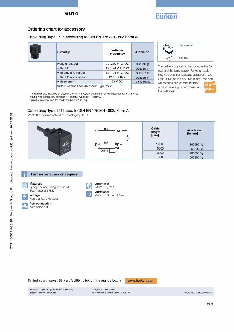
Ordering chart for accessory
Cable plug Type 2508 according to DIN EN 175 301 - 803 Form A
Circuitry Voltage/ Frequency Article no.
None (standard) 0 … 250 V AC/DC 008376 with LED 12 … 24 V AC/DC 008360 with LED and varistor 12 … 24 V AC/DC 008367 with LED and varistor 200 … 240 V 008369 with inverter1) 24 V DC on requestfurther versions see datasheet Type 2508
1 The inverter plug includes an electronic which is specially adapted for an electrical control with 3 wires Input 3 wire technology, common "-" polarity, two split "+" polarity. Output suitable for impulse model for Type 6013/6014
Flat seal
Fixing screw
The delivery of a cable plug includes the flat seal and the fixing screw. For other cable plug versions, see separate datasheet Type 2508. Click on the box “More info.” and you will come to our website for this product where you can download the datasheet.
More
info.
To find your nearest Bürkert facility, click on the orange box www.burkert.com
In case of special application conditions,please consult for advice.
Subject to alterations© Christian Bürkert GmbH & Co. KG 1804/10_EU-en_00895091
MaterialsEpoxy coil according to Form A Seal material EPDM
VoltageNon-standard voltages
Port connection With banjo nut
Approvals ATEX, UL, CSA
AdditionalOrifice: 1.2 mm, 3.0 mm
Cable plug Type 2513 acc. to DIN EN 175 301 - 803, Form AMeets the requirements of ATEX category 3 GD
BN
BU
GNYE
Cable length[mm]
Article no.[in mm]
12000 260893 5000 260892 3000 260891 300 260890