Embed Size (px)
Citation preview
NXP SemiconductorsApplication Note
Document Number: AN5221Rev. 1.0, 1/2016
© NXP Semiconductors N.V. 2016. All rights reserved.
1 IntroductionThe MC33879A is a configurable octal switch which drives a variety of loads. This application note illustrates how to use the MC33879A to drive a DC motor or a stepper motor. The configurations in this application note use the FRDM-33879A-EVB kit as the MC33879A evaluation platform.
Freescale analog ICs are manufactured using the SMARTMOS process, a combinational BiCMOS manufacturing flow integrating precision analog, power functions, and dense CMOS logic together on a single cost-effective die.
Contents
1 Introduction. . . . . . . . . . . . . . . . . . . . . . . . . . . . . . . . . . . . . . 1
2 Overview. . . . . . . . . . . . . . . . . . . . . . . . . . . . . . . . . . . . . . . . 2
3 DC Motor Configuration Example. . . . . . . . . . . . . . . . . . . . . 43.1 DC Motor Basics. . . . . . . . . . . . . . . . . . . . . . . . . . . . . . . 43.2 Experimental Setup . . . . . . . . . . . . . . . . . . . . . . . . . . . . 8
4 Stepper Motor Configuration Example . . . . . . . . . . . . . . . . 184.1 Stepper Motor Basics . . . . . . . . . . . . . . . . . . . . . . . . . . 184.2 Experimental Setup . . . . . . . . . . . . . . . . . . . . . . . . . . . 21
5 References . . . . . . . . . . . . . . . . . . . . . . . . . . . . . . . . . . . . . 29
6 Revision History . . . . . . . . . . . . . . . . . . . . . . . . . . . . . . . . . 30
Driving DC and Stepper MotorsFeaturing the MC33879A
Driving DC and Stepper Motors, Rev. 1.0
2 NXP Semiconductors
Overview
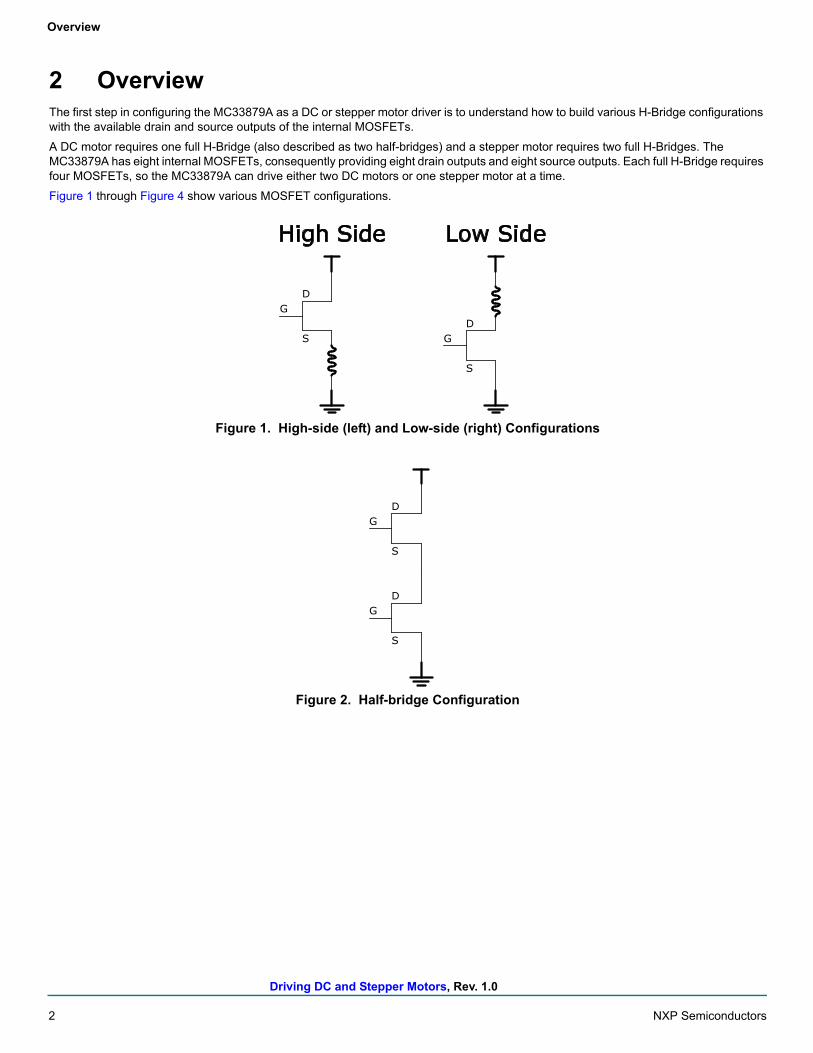
2 OverviewThe first step in configuring the MC33879A as a DC or stepper motor driver is to understand how to build various H-Bridge configurations with the available drain and source outputs of the internal MOSFETs.
A DC motor requires one full H-Bridge (also described as two half-bridges) and a stepper motor requires two full H-Bridges. The MC33879A has eight internal MOSFETs, consequently providing eight drain outputs and eight source outputs. Each full H-Bridge requires four MOSFETs, so the MC33879A can drive either two DC motors or one stepper motor at a time.
Figure 1 through Figure 4 show various MOSFET configurations.
Figure 1. High-side (left) and Low-side (right) Configurations
Figure 2. Half-bridge Configuration
G
S
DG
S
D
High Side Low Side
G
S
D
G
S
D
Driving DC and Stepper Motors, Rev. 1.0
NXP Semiconductors 3
Overview
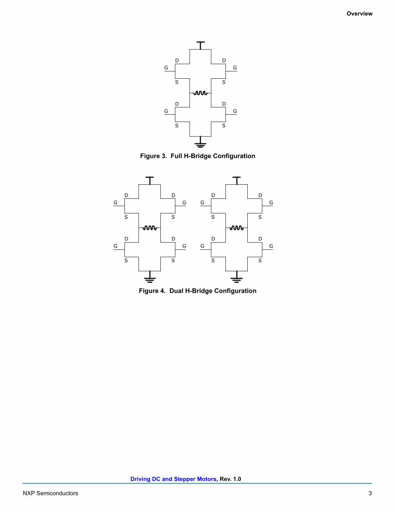
Figure 3. Full H-Bridge Configuration
Figure 4. Dual H-Bridge Configuration
G
S
D
G
S
D
S
D
S
D
G
G
G
S
D
G
S
D
S
D
S
D
G
G
G
S
D
G
S
D
S
D
S
D
G
G
Driving DC and Stepper Motors, Rev. 1.0
4 NXP Semiconductors
DC Motor Configuration Example
3 DC Motor Configuration Example
3.1 DC Motor BasicsDriving a DC motor requires one full H-Bridge. A full H-Bridge consists of two high-side MOSFETs and two low-side MOSFETs. In this example, MOSFETs 7 and 8 are high-side and MOSFETs 5 and 6 are low-side. Unlike a gate driver driving external MOSFETs, the MC33879A has internal MOSFETs. This means the gates of the MOSFETs are inside the device and only the sources and drains of these MOSFETs are accessible externally.
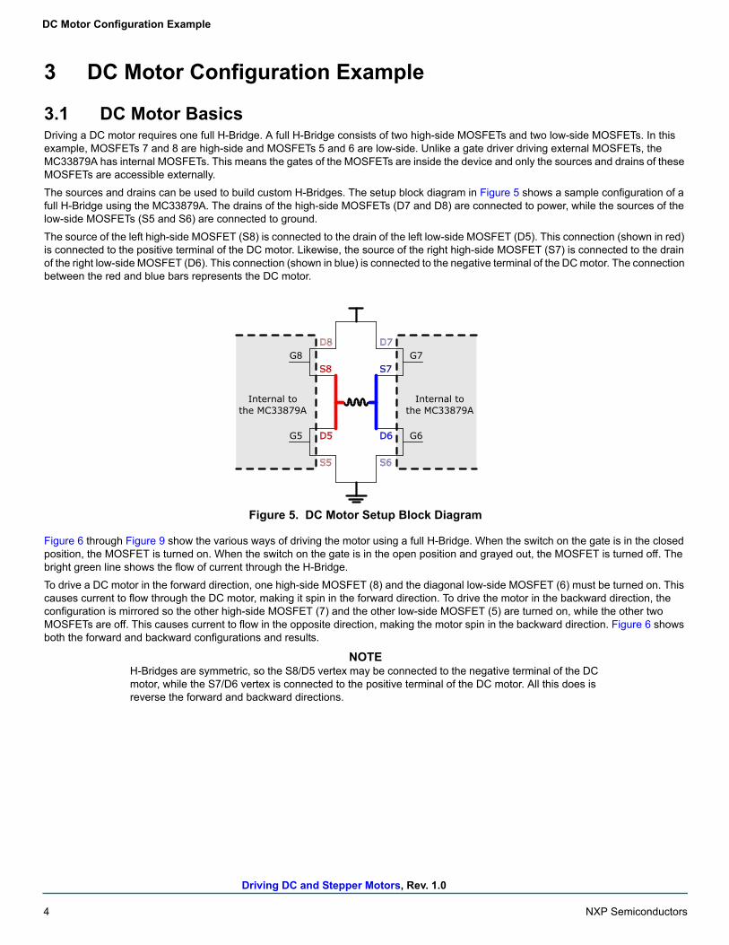
The sources and drains can be used to build custom H-Bridges. The setup block diagram in Figure 5 shows a sample configuration of a full H-Bridge using the MC33879A. The drains of the high-side MOSFETs (D7 and D8) are connected to power, while the sources of the low-side MOSFETs (S5 and S6) are connected to ground.
The source of the left high-side MOSFET (S8) is connected to the drain of the left low-side MOSFET (D5). This connection (shown in red) is connected to the positive terminal of the DC motor. Likewise, the source of the right high-side MOSFET (S7) is connected to the drain of the right low-side MOSFET (D6). This connection (shown in blue) is connected to the negative terminal of the DC motor. The connection between the red and blue bars represents the DC motor.
Figure 5. DC Motor Setup Block Diagram
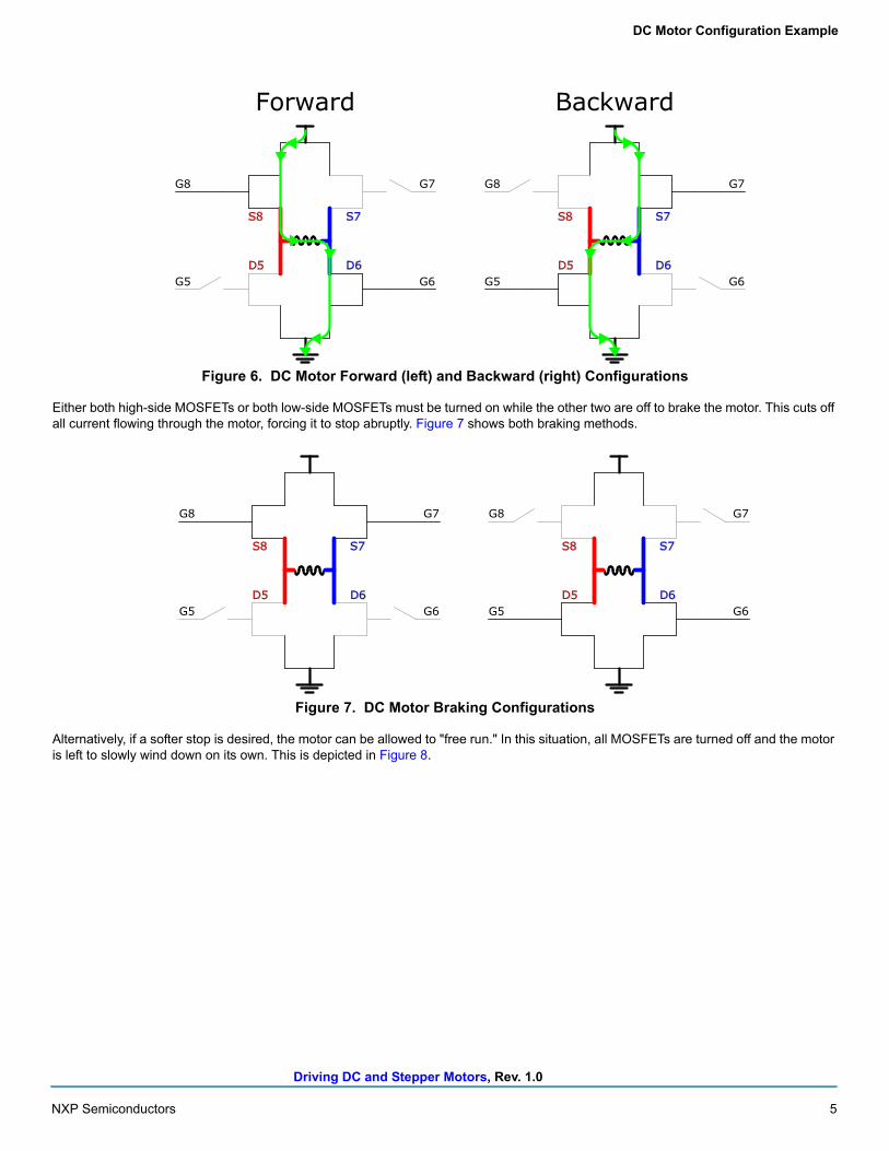
Figure 6 through Figure 9 show the various ways of driving the motor using a full H-Bridge. When the switch on the gate is in the closed position, the MOSFET is turned on. When the switch on the gate is in the open position and grayed out, the MOSFET is turned off. The bright green line shows the flow of current through the H-Bridge.
To drive a DC motor in the forward direction, one high-side MOSFET (8) and the diagonal low-side MOSFET (6) must be turned on. This causes current to flow through the DC motor, making it spin in the forward direction. To drive the motor in the backward direction, the configuration is mirrored so the other high-side MOSFET (7) and the other low-side MOSFET (5) are turned on, while the other two MOSFETs are off. This causes current to flow in the opposite direction, making the motor spin in the backward direction. Figure 6 shows both the forward and backward configurations and results.
NOTEH-Bridges are symmetric, so the S8/D5 vertex may be connected to the negative terminal of the DC motor, while the S7/D6 vertex is connected to the positive terminal of the DC motor. All this does is reverse the forward and backward directions.
D5
S8
D6
S7G8
G5
G7
G6
Internal tothe MC33879A
Internal tothe MC33879A
D8
S5
D7
S6
Driving DC and Stepper Motors, Rev. 1.0
NXP Semiconductors 5
DC Motor Configuration Example
Figure 6. DC Motor Forward (left) and Backward (right) Configurations
Either both high-side MOSFETs or both low-side MOSFETs must be turned on while the other two are off to brake the motor. This cuts off all current flowing through the motor, forcing it to stop abruptly. Figure 7 shows both braking methods.
Figure 7. DC Motor Braking Configurations
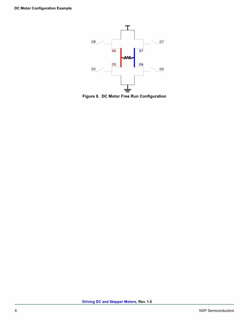
Alternatively, if a softer stop is desired, the motor can be allowed to "free run." In this situation, all MOSFETs are turned off and the motor is left to slowly wind down on its own. This is depicted in Figure 8.
D5
S8
D6
S7
G8
G5
G7
G6D5
S8
D6
S7
G8
G5
G7
G6
Forward Backward
D5
S8
D6
S7
G8
G5
G7
G6D5
S8
D6
S7
G8
G5
G7
G6
Driving DC and Stepper Motors, Rev. 1.0
6 NXP Semiconductors
DC Motor Configuration Example
Figure 8. DC Motor Free Run Configuration
D5
S8
D6
S7
G8
G5
G7
G6
Driving DC and Stepper Motors, Rev. 1.0
NXP Semiconductors 7
DC Motor Configuration Example
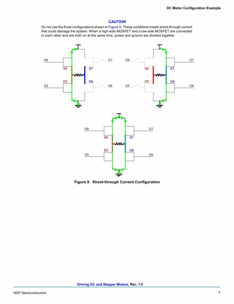
CAUTIONDo not use the three configurations shown in Figure 9. These conditions create shoot-through current that could damage the system. When a high-side MOSFET and a low-side MOSFET are connected to each other and are both on at the same time, power and ground are shorted together.
Figure 9. Shoot-through Current Configuration
D5
S8
D6
S7
G8
G5
G7
G6D5
S8
D6
S7
G8
G5
G7
G6
D5
S8
D6
S7
G8
G5
G7
G6
Driving DC and Stepper Motors, Rev. 1.0
8 NXP Semiconductors
DC Motor Configuration Example
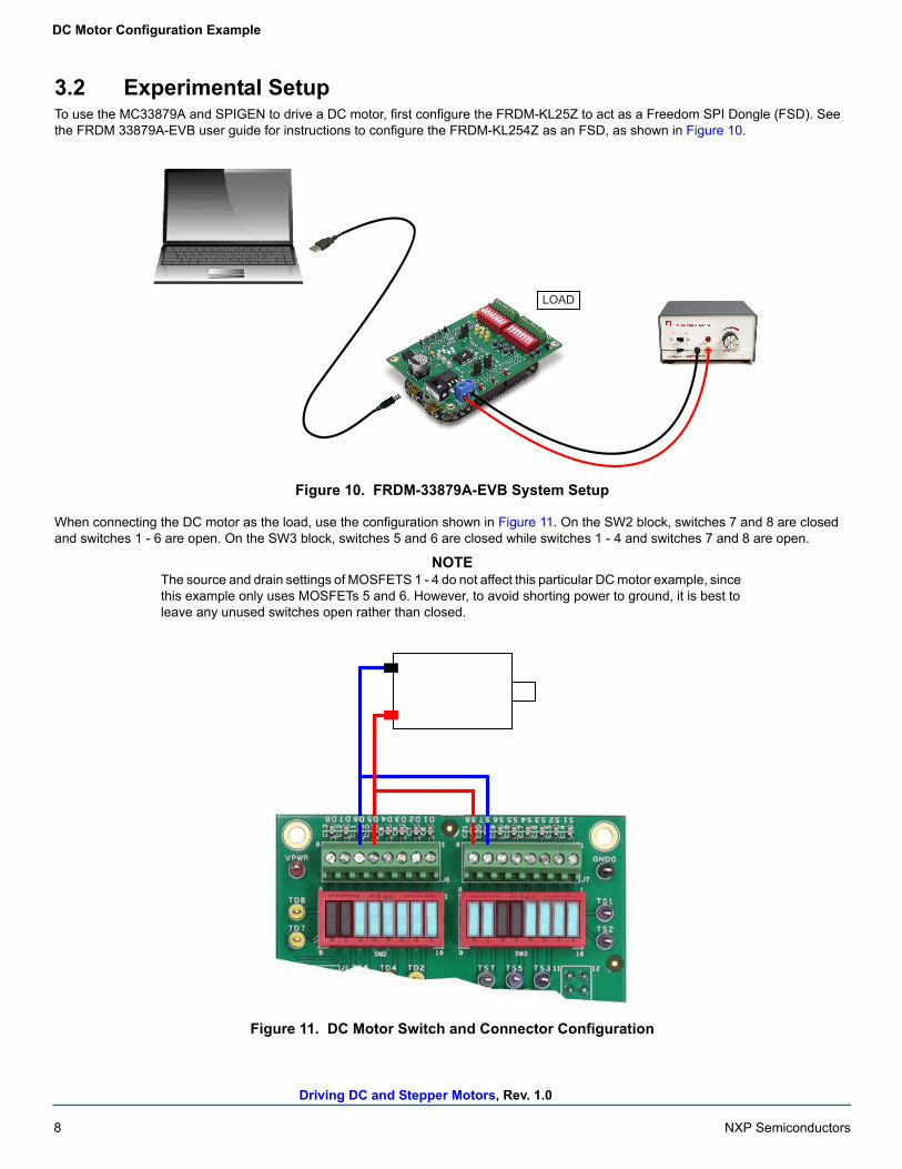
3.2 Experimental SetupTo use the MC33879A and SPIGEN to drive a DC motor, first configure the FRDM-KL25Z to act as a Freedom SPI Dongle (FSD). See the FRDM 33879A-EVB user guide for instructions to configure the FRDM-KL254Z as an FSD, as shown in Figure 10.
Figure 10. FRDM-33879A-EVB System Setup
When connecting the DC motor as the load, use the configuration shown in Figure 11. On the SW2 block, switches 7 and 8 are closed and switches 1 - 6 are open. On the SW3 block, switches 5 and 6 are closed while switches 1 - 4 and switches 7 and 8 are open.
NOTEThe source and drain settings of MOSFETS 1 - 4 do not affect this particular DC motor example, since this example only uses MOSFETs 5 and 6. However, to avoid shorting power to ground, it is best to leave any unused switches open rather than closed.
Figure 11. DC Motor Switch and Connector Configuration
LOAD
Driving DC and Stepper Motors, Rev. 1.0
NXP Semiconductors 9
DC Motor Configuration Example
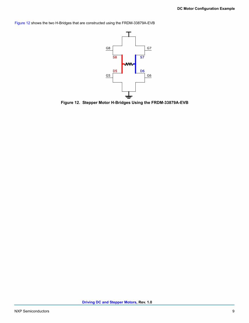
Figure 12 shows the two H-Bridges that are constructed using the FRDM-33879A-EVB
Figure 12. Stepper Motor H-Bridges Using the FRDM-33879A-EVB
D5
S8
D6
S7
G8
G5
G7
G6
Driving DC and Stepper Motors, Rev. 1.0
10 NXP Semiconductors
DC Motor Configuration Example
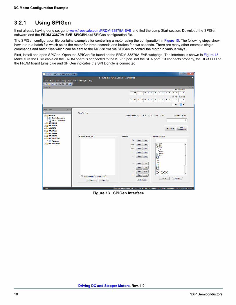
3.2.1 Using SPIGenIf not already having done so, go to www.freescale.com/FRDM-33879A-EVB and find the Jump Start section. Download the SPIGen software and the FRDM-33879A-EVB-SPIGEN.spi SPIGen configuration file.
The SPIGen configuration file contains examples for controlling a motor using the configuration in Figure 10. The following steps show how to run a batch file which spins the motor for three seconds and brakes for two seconds. There are many other example single commands and batch files which can be sent to the MC33879A via SPIGen to control the motor in various ways.
First, install and open SPIGen. Open the SPIGen file found on the FRDM-33879A-EVB webpage. The interface is shown in Figure 13. Make sure the USB cable on the FRDM board is connected to the KL25Z port, not the SDA port. If it connects properly, the RGB LED on the FRDM board turns blue and SPIGen indicates the SPI Dongle is connected.
Figure 13. SPIGen Interface
Driving DC and Stepper Motors, Rev. 1.0
NXP Semiconductors 11
DC Motor Configuration Example
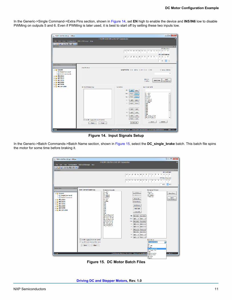
In the Generic->Single Command->Extra Pins section, shown in Figure 14, set EN high to enable the device and IN5/IN6 low to disable PWMing on outputs 5 and 6. Even if PWMing is later used, it is best to start off by setting these two inputs low.
Figure 14. Input Signals Setup
In the Generic->Batch Commands->Batch Name section, shown in Figure 15, select the DC_single_brake batch. This batch file spins the motor for some time before braking it.
Figure 15. DC Motor Batch Files
Driving DC and Stepper Motors, Rev. 1.0
12 NXP Semiconductors
DC Motor Configuration Example
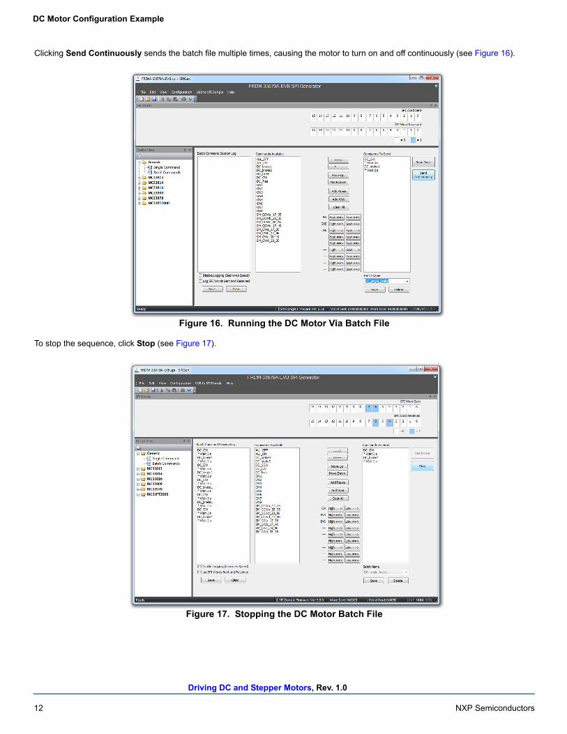
Clicking Send Continuously sends the batch file multiple times, causing the motor to turn on and off continuously (see Figure 16).
Figure 16. Running the DC Motor Via Batch File
To stop the sequence, click Stop (see Figure 17).
Figure 17. Stopping the DC Motor Batch File
Driving DC and Stepper Motors, Rev. 1.0
NXP Semiconductors 13
DC Motor Configuration Example
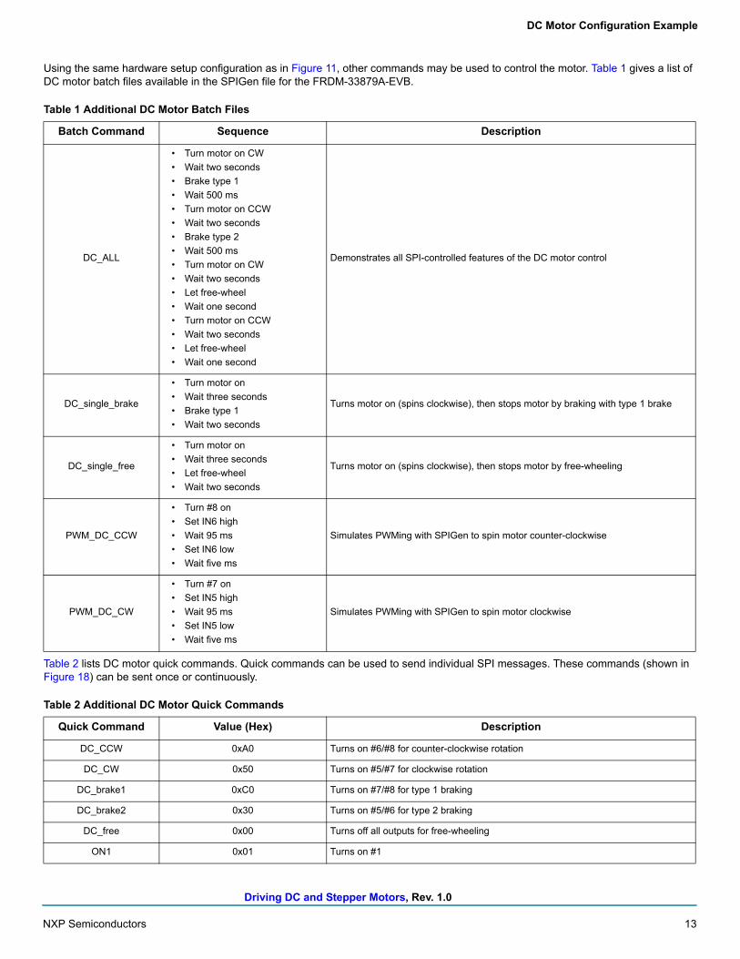
Using the same hardware setup configuration as in Figure 11, other commands may be used to control the motor. Table 1 gives a list of DC motor batch files available in the SPIGen file for the FRDM-33879A-EVB.
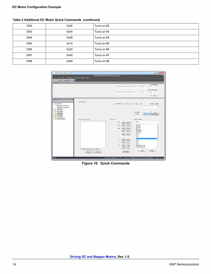
Table 2 lists DC motor quick commands. Quick commands can be used to send individual SPI messages. These commands (shown in Figure 18) can be sent once or continuously.
Table 1 Additional DC Motor Batch Files
Batch Command Sequence Description
DC_ALL
• Turn motor on CW
• Wait two seconds
• Brake type 1
• Wait 500 ms
• Turn motor on CCW
• Wait two seconds
• Brake type 2
• Wait 500 ms
• Turn motor on CW
• Wait two seconds
• Let free-wheel
• Wait one second
• Turn motor on CCW
• Wait two seconds
• Let free-wheel
• Wait one second
Demonstrates all SPI-controlled features of the DC motor control
DC_single_brake
• Turn motor on
• Wait three seconds
• Brake type 1
• Wait two seconds
Turns motor on (spins clockwise), then stops motor by braking with type 1 brake
DC_single_free
• Turn motor on
• Wait three seconds
• Let free-wheel
• Wait two seconds
Turns motor on (spins clockwise), then stops motor by free-wheeling
PWM_DC_CCW
• Turn #8 on
• Set IN6 high
• Wait 95 ms
• Set IN6 low
• Wait five ms
Simulates PWMing with SPIGen to spin motor counter-clockwise
PWM_DC_CW
• Turn #7 on
• Set IN5 high
• Wait 95 ms
• Set IN5 low
• Wait five ms
Simulates PWMing with SPIGen to spin motor clockwise
Table 2 Additional DC Motor Quick Commands
Quick Command Value (Hex) Description
DC_CCW 0xA0 Turns on #6/#8 for counter-clockwise rotation
DC_CW 0x50 Turns on #5/#7 for clockwise rotation
DC_brake1 0xC0 Turns on #7/#8 for type 1 braking
DC_brake2 0x30 Turns on #5/#6 for type 2 braking
DC_free 0x00 Turns off all outputs for free-wheeling
ON1 0x01 Turns on #1
Driving DC and Stepper Motors, Rev. 1.0
14 NXP Semiconductors
DC Motor Configuration Example
Figure 18. Quick Commands
ON2 0x02 Turns on #2
ON3 0x04 Turns on #3
ON4 0x08 Turns on #4
ON5 0x10 Turns on #5
ON6 0x20 Turns on #6
ON7 0x40 Turns on #7
ON8 0x80 Turns on #8
Table 2 Additional DC Motor Quick Commands (continued)
Driving DC and Stepper Motors, Rev. 1.0
NXP Semiconductors 15
DC Motor Configuration Example
3.2.2 Using mbedExample source code is available on the mbed™ website www.mbed.com. The FRDM-KL25Z must be configured as an mbed dongle, to run the mbed examples. Follow the instructions on the mbed website to configure the FRDM-KL25Z, then import the program for running a DC motor here: https://developer.mbed.org/teams/Freescale/code/FRDM-33879A-EVB_Brushed_DC_Motor_Control.
Major sections of the source code are described by the following. The code may be modified using the mbed compiler to fit the needs of the application. Alternatively, if another programming language or compiler is used, the code may also be used as pseudocode.
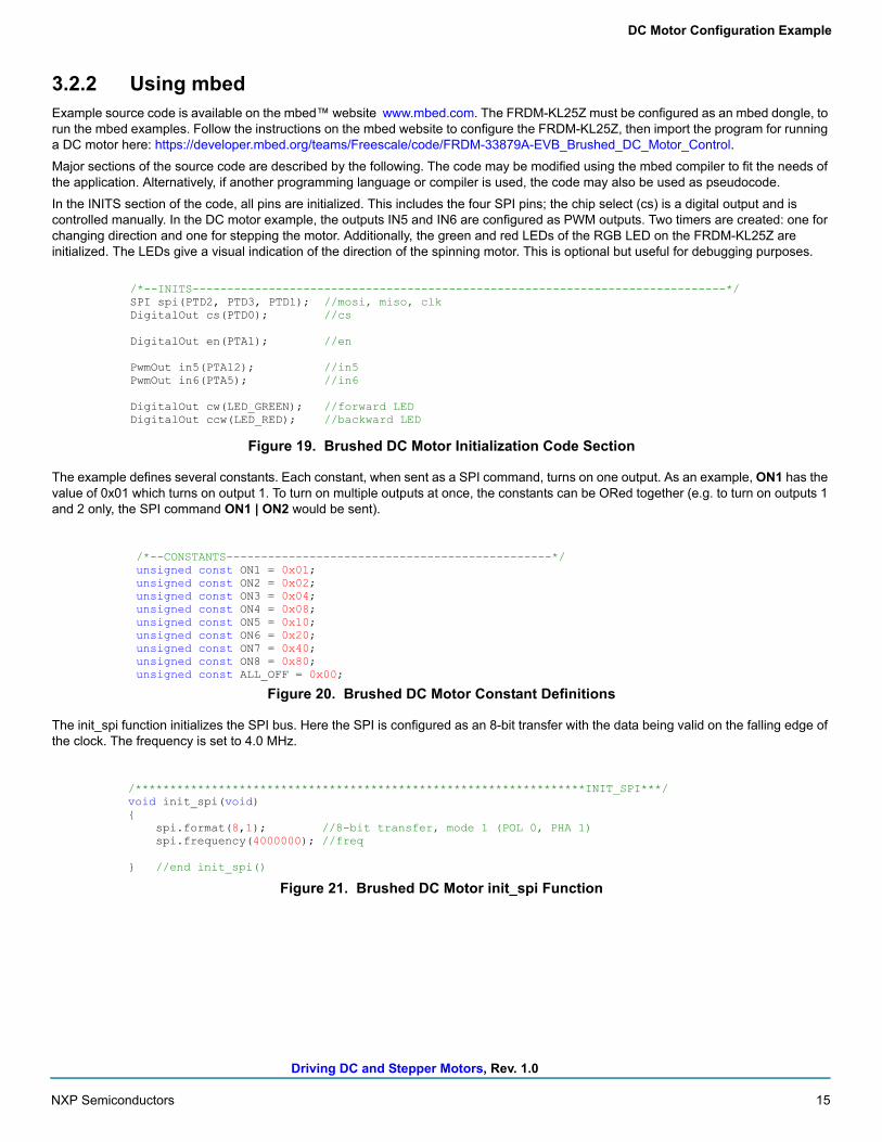
In the INITS section of the code, all pins are initialized. This includes the four SPI pins; the chip select (cs) is a digital output and is controlled manually. In the DC motor example, the outputs IN5 and IN6 are configured as PWM outputs. Two timers are created: one for changing direction and one for stepping the motor. Additionally, the green and red LEDs of the RGB LED on the FRDM-KL25Z are initialized. The LEDs give a visual indication of the direction of the spinning motor. This is optional but useful for debugging purposes.
Figure 19. Brushed DC Motor Initialization Code Section
The example defines several constants. Each constant, when sent as a SPI command, turns on one output. As an example, ON1 has the value of 0x01 which turns on output 1. To turn on multiple outputs at once, the constants can be ORed together (e.g. to turn on outputs 1 and 2 only, the SPI command ON1 | ON2 would be sent).
Figure 20. Brushed DC Motor Constant Definitions
The init_spi function initializes the SPI bus. Here the SPI is configured as an 8-bit transfer with the data being valid on the falling edge of the clock. The frequency is set to 4.0 MHz.
Figure 21. Brushed DC Motor init_spi Function
/*--INITS-----------------------------------------------------------------------------*/SPI spi(PTD2, PTD3, PTD1); //mosi, miso, clkDigitalOut cs(PTD0); //cs
DigitalOut en(PTA1); //en
PwmOut in5(PTA12); //in5PwmOut in6(PTA5); //in6
DigitalOut cw(LED_GREEN); //forward LEDDigitalOut ccw(LED_RED); //backward LED
/*--CONSTANTS-----------------------------------------------*/unsigned const ON1 = 0x01;unsigned const ON2 = 0x02;unsigned const ON3 = 0x04;unsigned const ON4 = 0x08;unsigned const ON5 = 0x10;unsigned const ON6 = 0x20;unsigned const ON7 = 0x40;unsigned const ON8 = 0x80;unsigned const ALL_OFF = 0x00;
/*****************************************************************INIT_SPI***/void init_spi(void){
spi.format(8,1); //8-bit transfer, mode 1 (POL 0, PHA 1)spi.frequency(4000000); //freq
} //end init_spi()

Driving DC and Stepper Motors, Rev. 1.0
16 NXP Semiconductors
DC Motor Configuration Example
The MC33879A actually communicates via 16-bit SPI messages. However, the KL25Z microcontroller supports 8-bit SPI messages only. Fortunately, since the chip select can be controlled manually, two 8-bit words can be sent to create one 16-bit SPI message. The chip select is pulled low at the beginning of the transfer and is only pulled high again once the second word has been sent.
Figure 22. Brushed DC Motor send_spi Function
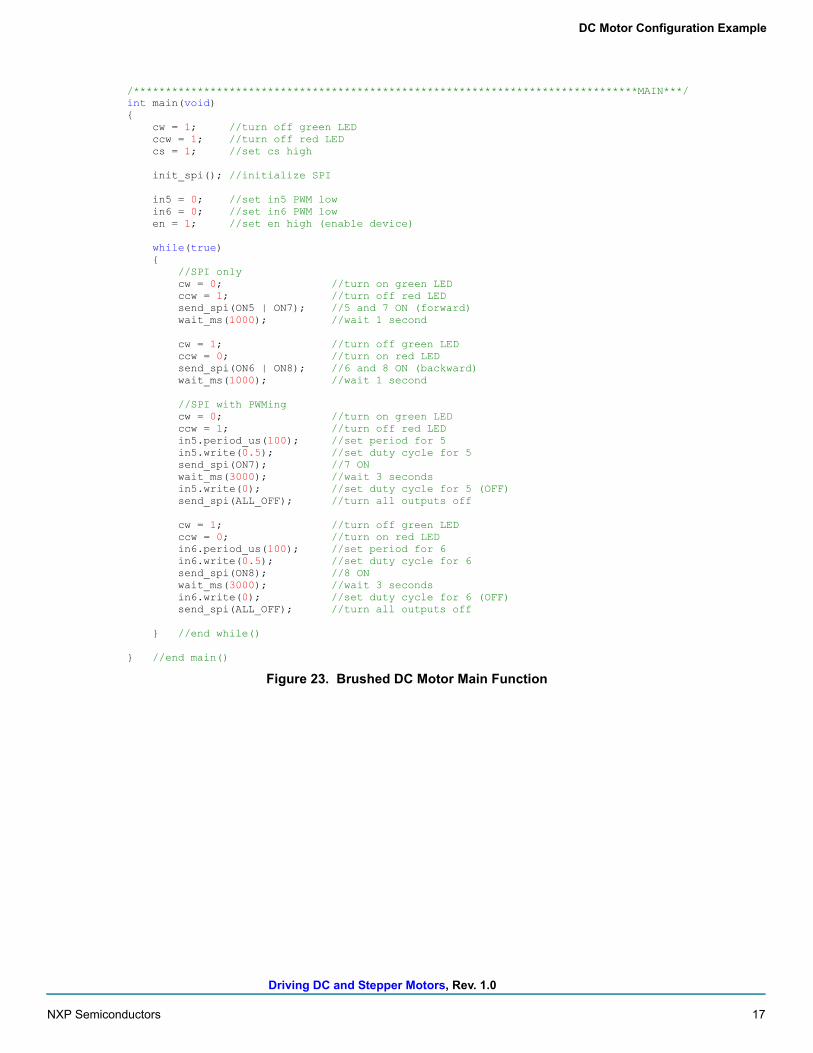
The code in the first part of main turns all LEDs off, pulls the chip select high, initializes the SPI, sets IN5 and IN6 low initially, and enables the device. The code making the motor spin is inside the while loop, which runs indefinitely. The first block of code makes the motor spin in a clockwise direction by turning on outputs 5 and 7, and then leaves them on for one second. Then outputs 6 and 8 are turned on while outputs 5 and 7 are turned off again, making the motor spin in a counterclockwise direction for one second. The PWMing function of the device is demonstrated in the next section. Here IN5 is set up to PWM with a period of 100 microseconds and a 50% duty cycle. Once the PWM is set up and started, output 7 is turned on via the SPI. After three seconds, the PWM output is turned off by setting the duty cycle to 0. Then all outputs are turned off. This sequence is then repeated for IN6 and output 8.
Note that the RGB LED on the FRDM-KL25Z changes color depending on which direction the motor is spinning. Even though the LED should be green when going forward and red when going backward, it actually is indigo and pink, respectively, due to the blue LED of the RGB LED being connected to one of the SPI signals.
/**************************************************************SEND_SPI***/void send_spi(unsigned const word){
cs = 0; //set cs lowspi.write(0x00); //send 0x00spi.write(word); //send 0xXXcs = 1; //set cs high
} //end send_spi()
Driving DC and Stepper Motors, Rev. 1.0
NXP Semiconductors 17
DC Motor Configuration Example
Figure 23. Brushed DC Motor Main Function
/*******************************************************************************MAIN***/int main(void){
cw = 1; //turn off green LEDccw = 1; //turn off red LEDcs = 1; //set cs high
init_spi(); //initialize SPI
in5 = 0; //set in5 PWM lowin6 = 0; //set in6 PWM lowen = 1; //set en high (enable device)
while(true){
//SPI onlycw = 0; //turn on green LEDccw = 1; //turn off red LEDsend_spi(ON5 | ON7); //5 and 7 ON (forward)wait_ms(1000); //wait 1 second
cw = 1; //turn off green LEDccw = 0; //turn on red LEDsend_spi(ON6 | ON8); //6 and 8 ON (backward)wait_ms(1000); //wait 1 second
//SPI with PWMingcw = 0; //turn on green LEDccw = 1; //turn off red LEDin5.period_us(100); //set period for 5in5.write(0.5); //set duty cycle for 5send_spi(ON7); //7 ONwait_ms(3000); //wait 3 secondsin5.write(0); //set duty cycle for 5 (OFF)send_spi(ALL_OFF); //turn all outputs off
cw = 1; //turn off green LEDccw = 0; //turn on red LEDin6.period_us(100); //set period for 6in6.write(0.5); //set duty cycle for 6send_spi(ON8); //8 ONwait_ms(3000); //wait 3 secondsin6.write(0); //set duty cycle for 6 (OFF)send_spi(ALL_OFF); //turn all outputs off
} //end while()
} //end main()
Driving DC and Stepper Motors, Rev. 1.0
18 NXP Semiconductors
Stepper Motor Configuration Example
4 Stepper Motor Configuration Example
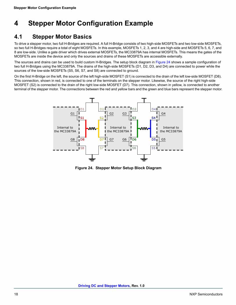
4.1 Stepper Motor BasicsTo drive a stepper motor, two full H-Bridges are required. A full H-Bridge consists of two high-side MOSFETs and two low-side MOSFETs, so two full H-Bridges require a total of eight MOSFETs. In this example, MOSFETs 1, 2, 3, and 4 are high-side and MOSFETs 5, 6, 7, and 8 are low-side. Unlike a gate driver which drives external MOSFETs, the MC33879A has internal MOSFETs. This means the gates of the MOSFETs are inside the device and only the sources and drains of these MOSFETs are accessible externally.
The sources and drains can be used to build custom H-Bridges. The setup block diagram in Figure 24 shows a sample configuration of two full H-Bridges using the MC33879A. The drains of the high-side MOSFETs (D1, D2, D3, and D4) are connected to power while the sources of the low-side MOSFETs (S5, S6, S7, and S8) are connected to ground.
On the first H-Bridge on the left, the source of the left high-side MOSFET (S1) is connected to the drain of the left low-side MOSFET (D8). This connection, shown in red, is connected to one of the terminals on the stepper motor. Likewise, the source of the right high-side MOSFET (S2) is connected to the drain of the right low-side MOSFET (D7). This connection, shown in yellow, is connected to another terminal of the stepper motor. The connections between the red and yellow bars and the green and blue bars represent the stepper motor.
Figure 24. Stepper Motor Setup Block Diagram
Internal tothe MC33879A
Internal tothe MC33879A
G1
G8
G2
G7D8
S1
D7
S2
D1
S8
D2
S7
Internal tothe MC33879A
G3
G6
G4
G5D6
S3
D5
S4
D3
S6
D4
S5
Driving DC and Stepper Motors, Rev. 1.0
NXP Semiconductors 19
Stepper Motor Configuration Example
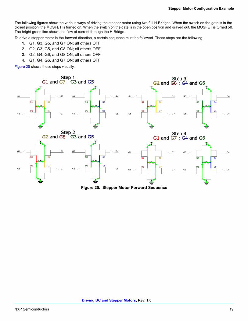
The following figures show the various ways of driving the stepper motor using two full H-Bridges. When the switch on the gate is in the closed position, the MOSFET is turned on. When the switch on the gate is in the open position and grayed out, the MOSFET is turned off. The bright green line shows the flow of current through the H-Bridge.
To drive a stepper motor in the forward direction, a certain sequence must be followed. These steps are the following:
1. G1, G3, G5, and G7 ON; all others OFF
2. G2, G3, G5, and G8 ON; all others OFF
3. G2, G4, G6, and G8 ON; all others OFF
4. G1, G4, G6, and G7 ON; all others OFF
Figure 25 shows these steps visually.
Figure 25. Stepper Motor Forward Sequence
D8
S1
D7
S2
D6
S3
D5
S4
G1
G8 G6
G3G2 G4
G5G7
G1 and G7 : G3 and G5
D8
S1
D7
S2
D6
S3
D5
S4
G1
G8 G6
G3G2 G4
G5G7
G2 and G8 : G3 and G5
D8
S1
D7
S2
D6
S3
D5
S4
G1
G8 G6
G3G2 G4
G5G7
D8
S1
D7
S2
D6
S3
D5
S4
G1
G8 G6
G3G2 G4
G5G7
G1 and G7 : G4 and G6
G2 and G8 : G4 and G6Step 1
Step 2
Step 3
Step 4
Driving DC and Stepper Motors, Rev. 1.0
20 NXP Semiconductors
Stepper Motor Configuration Example
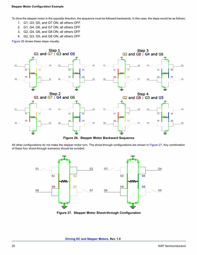
To drive the stepper motor in the opposite direction, the sequence must be followed backwards. In this case, the steps would be as follows:
1. G1, G3, G5, and G7 ON; all others OFF
2. G1, G4, G6, and G7 ON; all others OFF
3. G2, G4, G6, and G8 ON; all others OFF
4. G2, G3, G5, and G8 ON; all others OFF
Figure 26 shows these steps visually.
Figure 26. Stepper Motor Backward Sequence
All other configurations do not make the stepper motor turn. The shoot-through configurations are shown in Figure 27. Any combination of these four shoot-through scenarios should be avoided.
Figure 27. Stepper Motor Shoot-through Configuration
D8
S1
D7
S2
D6
S3
D5
S4
G1
G8 G6
G3G2 G4
G5G7
G1 and G7 : G3 and G5
D8
S1
D7
S2
D6
S3
D5
S4
G1
G8 G6
G3G2 G4
G5G7
G2 and G8 : G3 and G5
D8
S1
D7
S2
D6
S3
D5
S4
G1
G8 G6
G3G2 G4
G5G7
D8
S1
D7
S2
D6
S3
D5
S4
G1
G8 G6
G3G2 G4
G5G7
G1 and G7 : G4 and G6
G2 and G8 : G4 and G6Step 1
Step 2
Step 3
Step 4
D8
S1
D7
S2
D6
S3
D5
S4
G1
G8 G6
G3G2 G4
G5G7
Driving DC and Stepper Motors, Rev. 1.0
NXP Semiconductors 21
Stepper Motor Configuration Example
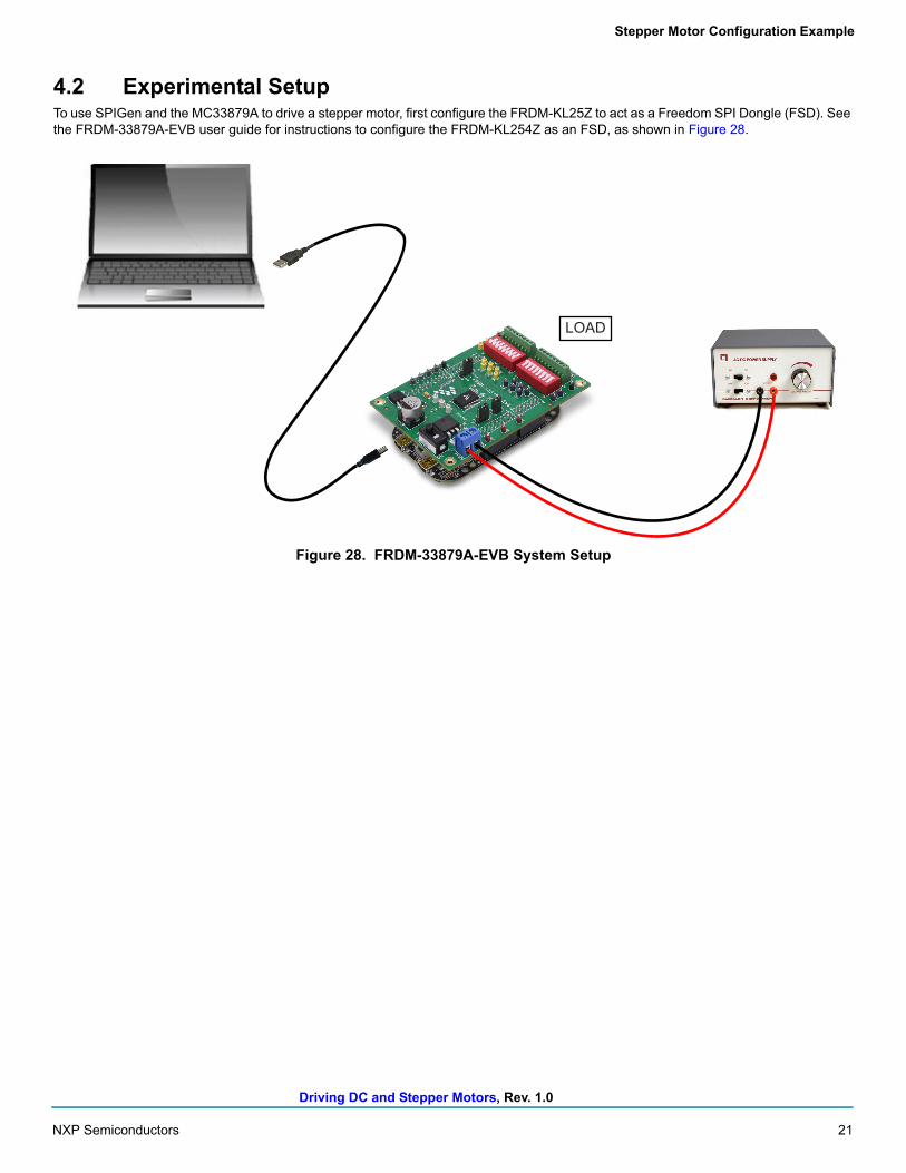
4.2 Experimental SetupTo use SPIGen and the MC33879A to drive a stepper motor, first configure the FRDM-KL25Z to act as a Freedom SPI Dongle (FSD). See the FRDM-33879A-EVB user guide for instructions to configure the FRDM-KL254Z as an FSD, as shown in Figure 28.
Figure 28. FRDM-33879A-EVB System Setup
LOAD
Driving DC and Stepper Motors, Rev. 1.0
22 NXP Semiconductors
Stepper Motor Configuration Example
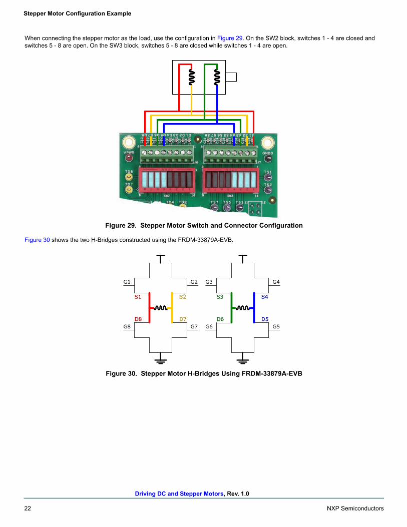
When connecting the stepper motor as the load, use the configuration in Figure 29. On the SW2 block, switches 1 - 4 are closed and switches 5 - 8 are open. On the SW3 block, switches 5 - 8 are closed while switches 1 - 4 are open.
Figure 29. Stepper Motor Switch and Connector Configuration
Figure 30 shows the two H-Bridges constructed using the FRDM-33879A-EVB.
Figure 30. Stepper Motor H-Bridges Using FRDM-33879A-EVB
D8
S1
D7
S2
D6
S3
D5
S4
G1
G8 G6
G3G2 G4
G5G7
Driving DC and Stepper Motors, Rev. 1.0
NXP Semiconductors 23
Stepper Motor Configuration Example
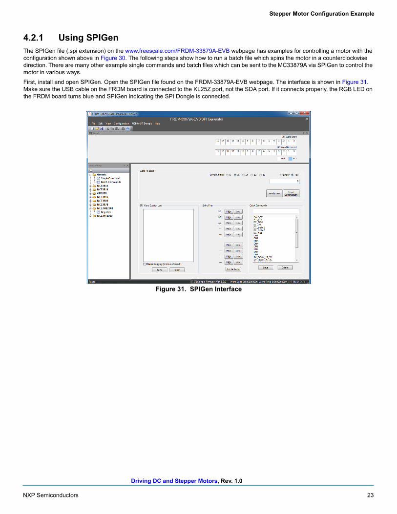
4.2.1 Using SPIGenThe SPIGen file (.spi extension) on the www.freescale.com/FRDM-33879A-EVB webpage has examples for controlling a motor with the configuration shown above in Figure 30. The following steps show how to run a batch file which spins the motor in a counterclockwise direction. There are many other example single commands and batch files which can be sent to the MC33879A via SPIGen to control the motor in various ways.
First, install and open SPIGen. Open the SPIGen file found on the FRDM-33879A-EVB webpage. The interface is shown in Figure 31. Make sure the USB cable on the FRDM board is connected to the KL25Z port, not the SDA port. If it connects properly, the RGB LED on the FRDM board turns blue and SPIGen indicating the SPI Dongle is connected.
Figure 31. SPIGen Interface
Driving DC and Stepper Motors, Rev. 1.0
24 NXP Semiconductors
Stepper Motor Configuration Example
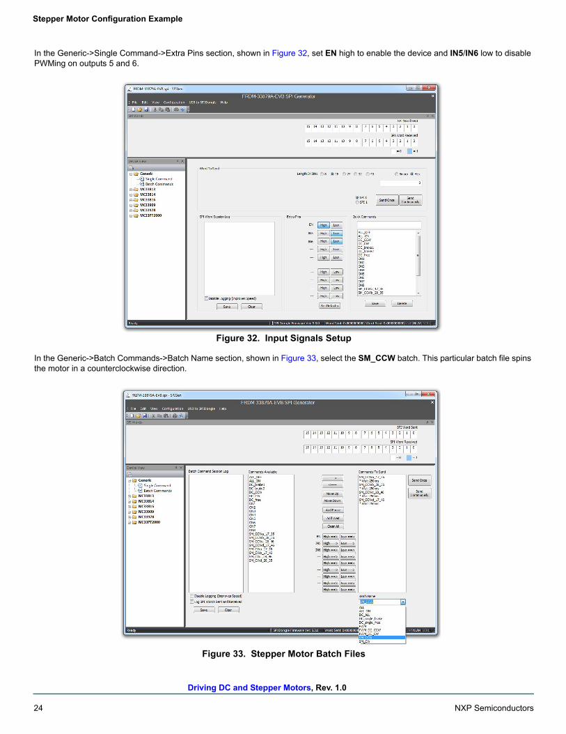
In the Generic->Single Command->Extra Pins section, shown in Figure 32, set EN high to enable the device and IN5/IN6 low to disable PWMing on outputs 5 and 6.
Figure 32. Input Signals Setup
In the Generic->Batch Commands->Batch Name section, shown in Figure 33, select the SM_CCW batch. This particular batch file spins the motor in a counterclockwise direction.
Figure 33. Stepper Motor Batch Files
Driving DC and Stepper Motors, Rev. 1.0
NXP Semiconductors 25
Stepper Motor Configuration Example
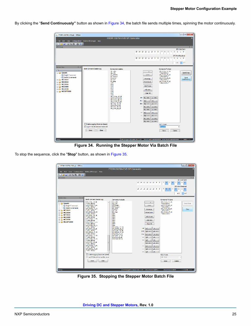
By clicking the “Send Continuously” button as shown in Figure 34, the batch file sends multiple times, spinning the motor continuously.
Figure 34. Running the Stepper Motor Via Batch File
To stop the sequence, click the "Stop" button, as shown in Figure 35.
Figure 35. Stopping the Stepper Motor Batch File
Driving DC and Stepper Motors, Rev. 1.0
26 NXP Semiconductors
Stepper Motor Configuration Example
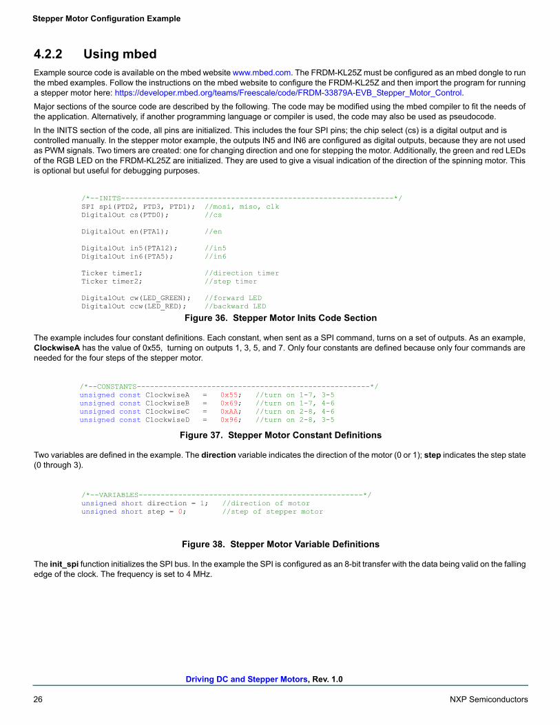
4.2.2 Using mbedExample source code is available on the mbed website www.mbed.com. The FRDM-KL25Z must be configured as an mbed dongle to run the mbed examples. Follow the instructions on the mbed website to configure the FRDM-KL25Z and then import the program for running a stepper motor here: https://developer.mbed.org/teams/Freescale/code/FRDM-33879A-EVB_Stepper_Motor_Control.
Major sections of the source code are described by the following. The code may be modified using the mbed compiler to fit the needs of the application. Alternatively, if another programming language or compiler is used, the code may also be used as pseudocode.
In the INITS section of the code, all pins are initialized. This includes the four SPI pins; the chip select (cs) is a digital output and is controlled manually. In the stepper motor example, the outputs IN5 and IN6 are configured as digital outputs, because they are not used as PWM signals. Two timers are created: one for changing direction and one for stepping the motor. Additionally, the green and red LEDs of the RGB LED on the FRDM-KL25Z are initialized. They are used to give a visual indication of the direction of the spinning motor. This is optional but useful for debugging purposes.
Figure 36. Stepper Motor Inits Code Section
The example includes four constant definitions. Each constant, when sent as a SPI command, turns on a set of outputs. As an example, ClockwiseA has the value of 0x55, turning on outputs 1, 3, 5, and 7. Only four constants are defined because only four commands are needed for the four steps of the stepper motor.
Figure 37. Stepper Motor Constant Definitions
Two variables are defined in the example. The direction variable indicates the direction of the motor (0 or 1); step indicates the step state (0 through 3).
Figure 38. Stepper Motor Variable Definitions
The init_spi function initializes the SPI bus. In the example the SPI is configured as an 8-bit transfer with the data being valid on the falling edge of the clock. The frequency is set to 4 MHz.
/*--INITS--------------------------------------------------------------*/SPI spi(PTD2, PTD3, PTD1); //mosi, miso, clkDigitalOut cs(PTD0); //cs
DigitalOut en(PTA1); //en
DigitalOut in5(PTA12); //in5DigitalOut in6(PTA5); //in6
Ticker timer1; //direction timerTicker timer2; //step timer
DigitalOut cw(LED_GREEN); //forward LEDDigitalOut ccw(LED_RED); //backward LED
/*--CONSTANTS-----------------------------------------------------*/unsigned const ClockwiseA = 0x55; //turn on 1-7, 3-5unsigned const ClockwiseB = 0x69; //turn on 1-7, 4-6unsigned const ClockwiseC = 0xAA; //turn on 2-8, 4-6unsigned const ClockwiseD = 0x96; //turn on 2-8, 3-5
/*--VARIABLES---------------------------------------------------*/unsigned short direction = 1; //direction of motorunsigned short step = 0; //step of stepper motor
Driving DC and Stepper Motors, Rev. 1.0
NXP Semiconductors 27
Stepper Motor Configuration Example
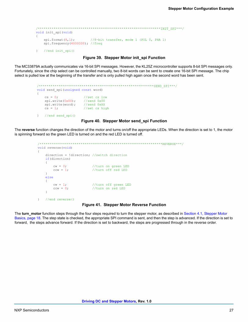
Figure 39. Stepper Motor init_spi Function
The MC33879A actually communicates via 16-bit SPI messages. However, the KL25Z microcontroller supports 8-bit SPI messages only. Fortunately, since the chip select can be controlled manually, two 8-bit words can be sent to create one 16-bit SPI message. The chip select is pulled low at the beginning of the transfer and is only pulled high again once the second word has been sent.
Figure 40. Stepper Motor send_spi Function
The reverse function changes the direction of the motor and turns on/off the appropriate LEDs. When the direction is set to 1, the motor is spinning forward so the green LED is turned on and the red LED is turned off.
Figure 41. Stepper Motor Reverse Function
The turn_motor function steps through the four steps required to turn the stepper motor, as described in Section 4.1, Stepper Motor Basics, page 18. The step state is checked, the appropriate SPI command is sent, and then the step is advanced. If the direction is set to forward, the steps advance forward. If the direction is set to backward, the steps are progressed through in the reverse order.
/***************************************************************INIT_SPI***/void init_spi(void){
spi.format(8,1); //8-bit transfer, mode 1 (POL 0, PHA 1)spi.frequency(4000000); //freq
} //end init_spi()
/***********************************************************SEND_SPI***/void send_spi(unsigned const word){
cs = 0; //set cs lowspi.write(0x00); //send 0x00spi.write(word); //send 0xXXcs = 1; //set cs high
} //end send_spi()
/***************************************************************REVERSE***/void reverse(void){
direction = !direction; //switch directionif(direction){
cw = 0; //turn on green LEDccw = 1; //turn off red LED
}else{
cw = 1; //turn off green LEDccw = 0; //turn on red LED
}
} //end reverse()
Driving DC and Stepper Motors, Rev. 1.0
28 NXP Semiconductors
Stepper Motor Configuration Example
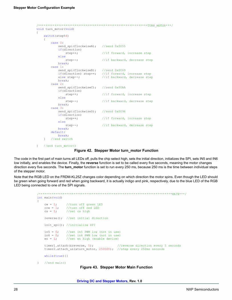
Figure 42. Stepper Motor turn_motor Function
The code in the first part of main turns all LEDs off, pulls the chip select high, sets the initial direction, initializes the SPI, sets IN5 and IN6 low initially, and enables the device. Finally, the reverse function is set to be called every five seconds, meaning the motor changes direction every five seconds. The turn_motor function is set to run every 250 ms, because 250 ms is the time between individual steps of the stepper motor.
Note that the RGB LED on the FRDM-KL25Z changes color depending on which direction the motor spins. Even though the LED should be green when going forward and red when going backward, it is actually indigo and pink, respectively, due to the blue LED of the RGB LED being connected to one of the SPI signals.
Figure 43. Stepper Motor Main Function
/************************************************************TURN_MOTOR***/void turn_motor(void){
switch(step%4){
case 0:send_spi(ClockwiseA); //send 0x0055if(direction)
step++; //if forward, increase stepelse
step--; //if backward, decrease stepbreak;
case 1:send_spi(ClockwiseB); //send 0x0069if(direction) step++; //if forward, increase stepelse step--; //if backward, decrease stepbreak;
case 2:send_spi(ClockwiseC); //send 0x00AAif(direction)
step++; //if forward, increase stepelse
step--; //if backward, decrease stepbreak;
case 3:send_spi(ClockwiseD); //send 0x0096if(direction)
step++; //if forward, increase stepelse
step--; //if backward, decrease stepbreak;
default:break;
} //end switch
} //end turn_motor()
/*************************************************************************MAIN***/int main(void){
cw = 1; //turn off green LEDccw = 1; //turn off red LEDcs = 1; //set cs high
reverse(); //set initial direction
init_spi(); //initialize SPI
in5 = 0; //set in5 PWM low (not in use)in6 = 0; //set in6 PWM low (not in use)en = 1; //set en high (enable device)
timer1.attach(&reverse, 5); //reverse direction every 5 secondstimer2.attach_us(&turn_motor, 250000); //step every 250ms seconds
while(true){}
} //end main()
Driving DC and Stepper Motors, Rev. 1.0
NXP Semiconductors 29
References
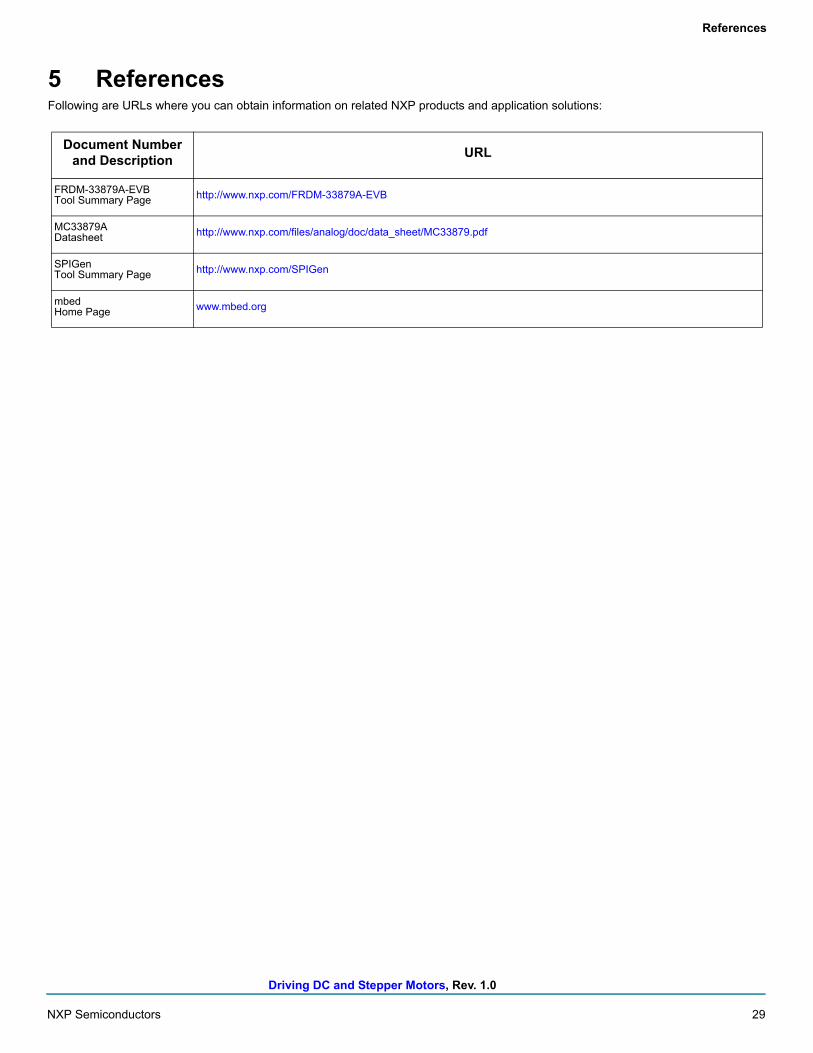
5 ReferencesFollowing are URLs where you can obtain information on related NXP products and application solutions:
Document Number and Description
URL
FRDM-33879A-EVBTool Summary Page http://www.nxp.com/FRDM-33879A-EVB
MC33879ADatasheet http://www.nxp.com/files/analog/doc/data_sheet/MC33879.pdf
SPIGenTool Summary Page http://www.nxp.com/SPIGen
mbedHome Page www.mbed.org
Driving DC and Stepper Motors, Rev. 1.0
30 NXP Semiconductors
Revision History
6 Revision History
Revision Date Description
1.0 1/2016 • Initial release
Information in this document is provided solely to enable system and software implementers to use Freescale
products. There are no express or implied copyright licenses granted hereunder to design or fabricate any integrated
circuits based on the information in this document.
Freescale reserves the right to make changes without further notice to any products herein. Freescale makes no
warranty, representation, or guarantee regarding the suitability of its products for any particular purpose, nor does
Freescale assume any liability arising out of the application or use of any product or circuit, and specifically disclaims
any and all liability, including without limitation consequential or incidental damages. “Typical” parameters that may be
provided in Freescale data sheets and/or specifications can and do vary in different applications, and actual
performance may vary over time. All operating parameters, including “typicals,” must be validated for each customer
application by customer’s technical experts. Freescale does not convey any license under its patent rights nor the
rights of others. Freescale sells products pursuant to standard terms and conditions of sale, which can be found at the
following address:
http://www.nxp.com/terms-of-use.html.
How to Reach Us:
Home Page: NXP.com
Web Support: http://www.nxp.com/support
Freescale and the Freescale logo are trademarks of Freescale Semiconductor, Inc., Reg. U.S. Pat. & Tm. Off.
SMARTMOS is a trademark of Freescale Semiconductor, Inc. All other product or service names are the property of
their respective owners.
© NXP Semiconductors N.V. 2016. All rights reserved.
Document Number: AN5221Rev. 1.0
1/2016