Embed Size (px)
Citation preview
Better surface finish
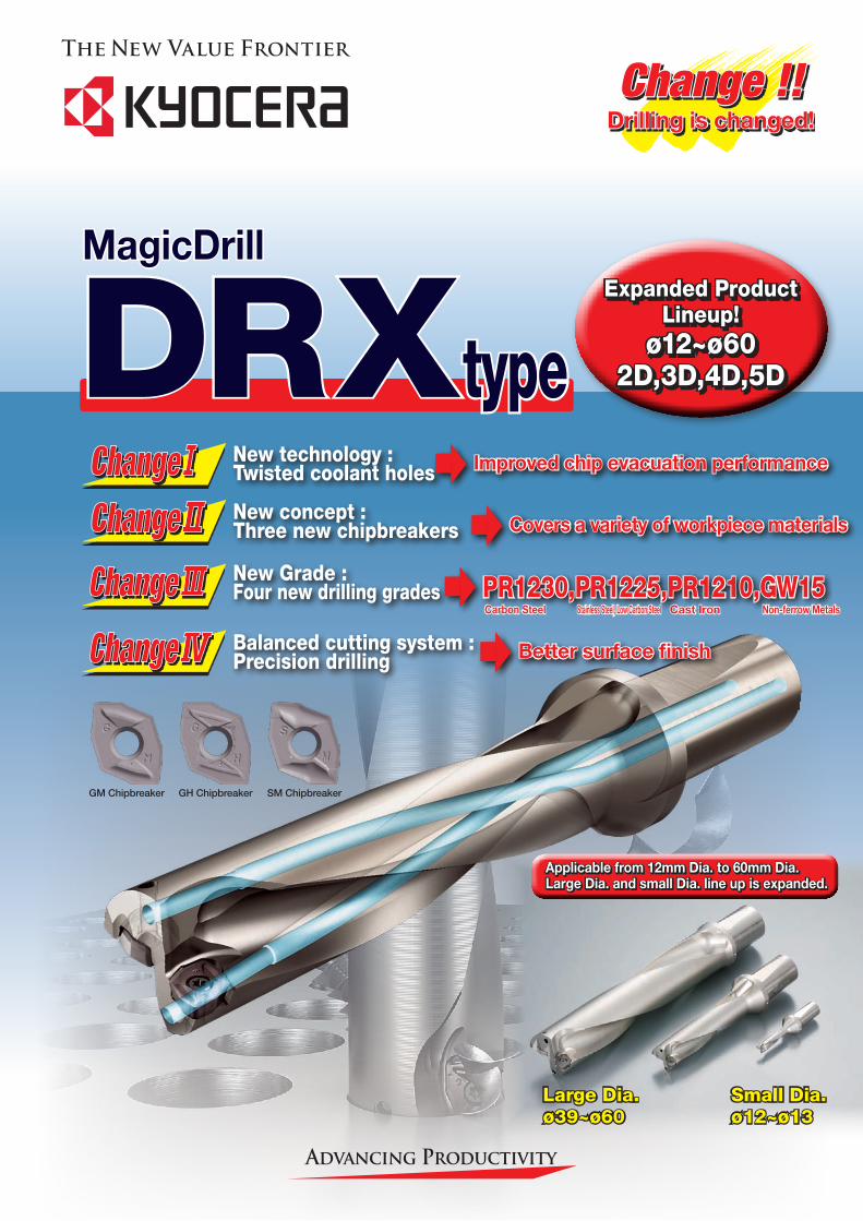
Expanded Product Lineup!
ø12~ø602D,3D,4D,5D
Applicable from 12mm Dia. to 60mm Dia.Large Dia. and small Dia. line up is expanded.
Change !!Drilling is changed!
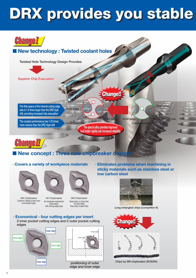
New technology : Twisted coolant holes
Balanced cutting system : Precision drilling
New Grade : Four new drilling grades
New concept : Three new chipbreakers
Large Dia.ø39~ø60
Small Dia.ø12~ø13
Improved chip evacuation performance
Covers a variety of workpiece materials
PR1230,PR1225,PR1210,GW15 Carbon Steel Stainless Steel, Low Carbon Steel Cast Iron Non-ferrow Metals
GM Chipbreaker GH Chipbreaker SM Chipbreaker
MagicDrill
DRXtype
DRX provides you stable and efficient drilling
■ New concept : Three new chipbreaker designs · Covers a variety of workpiece materials
Inner edge
Inner edge
Outer edge
Outer edge Chips by SM chipbreaker (SUS304)
Long entangled chips (competitor A)
· Economical - four cutting edges per insert2 inner pocket cutting edges and 2 outer pocket cutting edges
· Eliminates problems when machining in sticky materials such as stainless steel or low carbon steel
GM ChipbreakerCarbon Steel,Cast Iron
universal type
GH Chipbreakerfor hardened material,for
interruptionwith strong edge type
SM ChipbreakerStainless Steel, Low Carbon Steel,
Non-ferrous MetalsSharp cutting, for deeper drilling
Change!!
Inner edge
Outer edge
positioning of outer edge and inner edge
Twisted Hole Technology Design Provides
■ New technology : Twisted coolant holes
Change!!
Conventional tools
Inner edge
Inner edgeOuter edge
Outer edge
Superior Chip Evacuation
Single coolant hole
Double coolant hole
The special alloy provides improvedtool holder rigidity and increased reliability
The flute space of the internal cutting edge side is 1.6 times larger than the DRZ style drill, providing increased chip evacuation
The coolant performance has 1.25 times more volume than the DRZ style drill
1
DRX provides you stable and efficient drilling
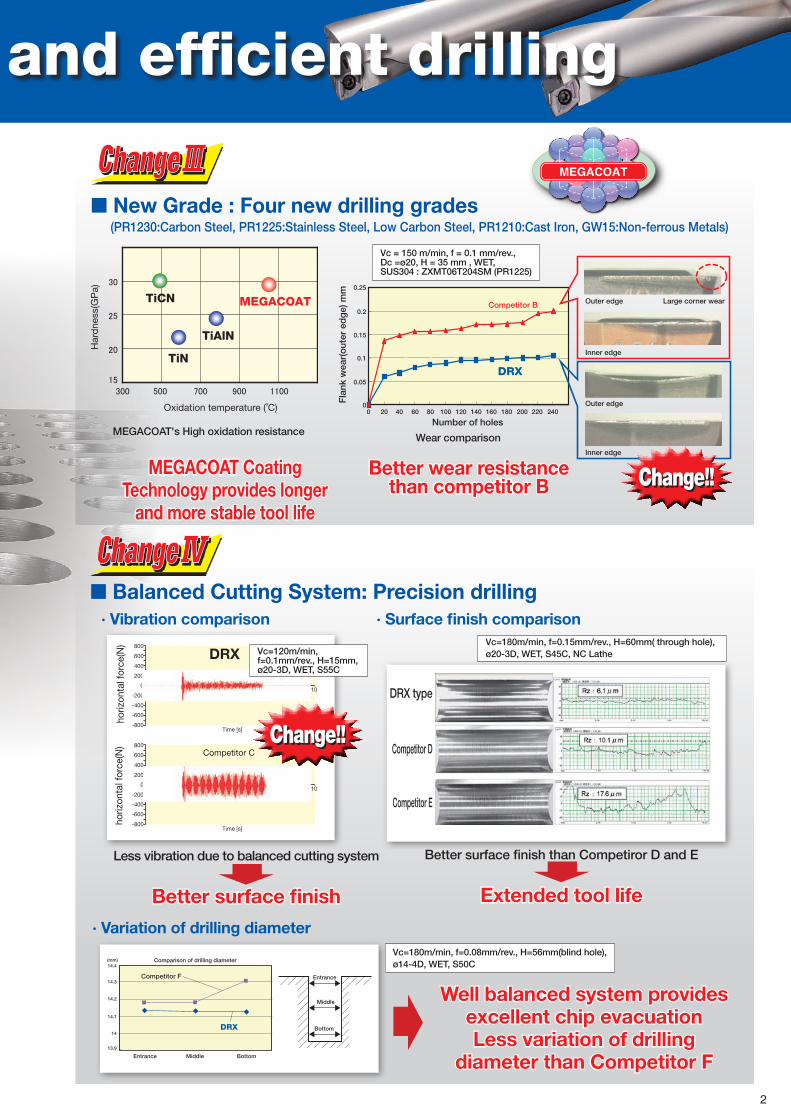
■ New Grade : Four new drilling grades (PR1230:Carbon Steel, PR1225:Stainless Steel, Low Carbon Steel, PR1210:Cast Iron, GW15:Non-ferrous Metals)
MEGACOAT's High oxidation resistance
MEGACOAT Coating Technology provides longer
and more stable tool life
Better wear resistance than competitor B
TiCN
TiAlN
TiN
MEGACOAT
Har
dne
ss(G
Pa)
Oxidation temperature (˚C)
Number of holes
Competitor B Outer edge Large corner wear
Inner edge
Outer edge
Inner edge
Fla
nk w
ear(
out
er e
dg
e) m
m
0 20 40 60 80 100 120 140 160 180 200 220 2400
0.05
0.1
0.15
0.2
0.25
DRX
Change!!
Wear comparison
Vc = 150 m/min, f = 0.1 mm/rev., Dc =ø20, H = 35 mm , WET, SUS304 : ZXMT06T204SM (PR1225)
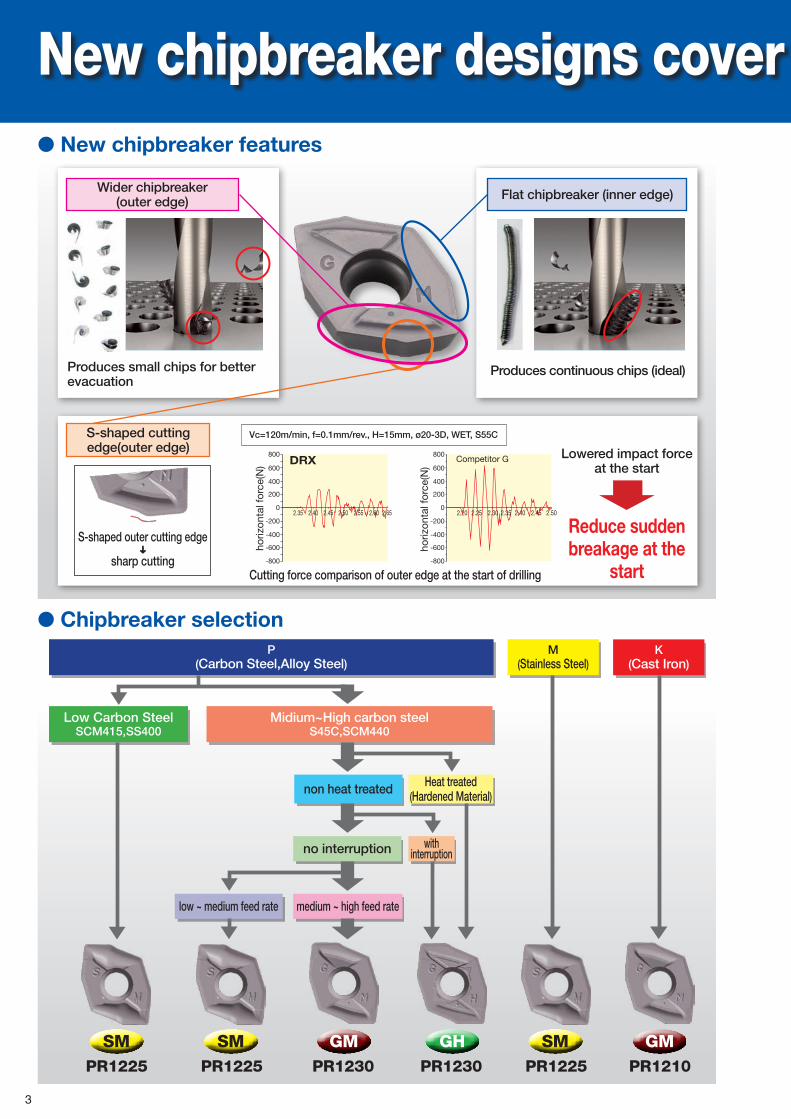
■ Balanced Cutting System: Precision drilling· Vibration comparison
· Variation of drilling diameter
· Surface finish comparisonVc=180m/min, f=0.15mm/rev., H=60mm( through hole), ø20-3D, WET, S45C, NC Lathe
Vc=180m/min, f=0.08mm/rev., H=56mm(blind hole),ø14-4D, WET, S50C
DRX type
Competitor D
Competitor E
Better surface finish than Competiror D and E
Extended tool life
Less vibration due to balanced cutting system
Better surface finish
1
800
600
400
200
-200
-400
-600
-800
02 3 4
Time [s]
5 6 7 8 9 10
1
800
600
400
200
-200
-400
-600
-800
02 3 4
Time [s]
5 6 7 8 9 10
Competitor C
DRX
horiz
onta
l for
ce(N
)ho
rizon
tal f
orce
(N)
Entrance
Entrance
Middle
Competitor F
Middle
Bottom
Bottom
Comparison of drilling diameter14.4(mm)
14.3
14.2
14.1
14
13.9
DRX
Well balanced system provides excellent chip evacuation Less variation of drilling
diameter than Competitor F
Change!!
Vc=120m/min, f=0.1mm/rev., H=15mm, ø20-3D, WET, S55C
2
MEGACOATMEGACOAT Hard
SMPR1225
GHPR1230
GMPR1230
New chipbreaker designs cover a variety of workplace materials
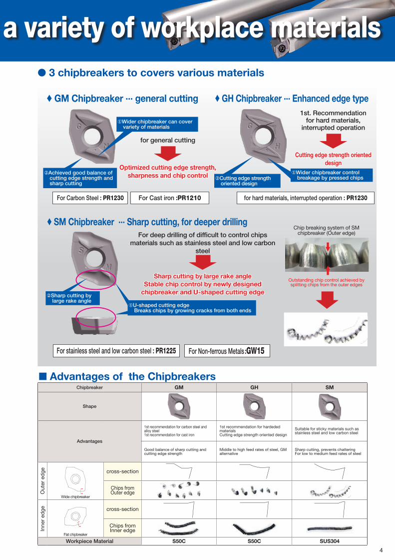
Produces small chips for better evacuation
Produces continuous chips (ideal)
S-shaped outer cutting edge➜
sharp cutting
Vc=120m/min, f=0.1mm/rev., H=15mm, ø20-3D, WET, S55C
DRX
horiz
onta
l for
ce(N
)
horiz
onta
l for
ce(N
)
Competitor G800
600
400
200
2.40 2.452.35 2.50 2.55 2.60 2.650
-200
-400
-600
-800
800
600
400
200
2.20 2.25 2.30 2.35 2.40 2.45 2.500
-200
-400
-600
-800
Lowered impact force at the start
Reduce sudden breakage at the
startCutting force comparison of outer edge at the start of drilling
● Chipbreaker selectionP
(Carbon Steel,Alloy Steel)
Low Carbon SteelSCM415,SS400
Midium~High carbon steelS45C,SCM440
Heat treated(Hardened Material)non heat treated
low ~ medium feed rate
no interruption
medium ~ high feed rate
M(Stainless Steel)
K(Cast Iron)
SM SM GMPR1225 PR1225 PR1210
● New chipbreaker features
S-shaped cutting edge(outer edge)
Flat chipbreaker (inner edge)Wider chipbreaker (outer edge)
with interruption
3
for general cutting
Optimized cutting edge strength, sharpness and chip control
1st. Recommendation for hard materials,
interrupted operation
Cutting edge strength oriented design
● 3 chipbreakers to covers various materials
♦ GM Chipbreaker ··· general cutting ♦ GH Chipbreaker ··· Enhanced edge type
①Wider chipbreaker can cover variety of materials
①Wider chipbreaker control breakage by pressed chips②Cutting edge strength
oriented design
②Achieved good balance of cutting edge strength and sharp cutting
For Carbon Steel : PR1230 for hard materials, interrupted operation : PR1230For Cast iron :PR1210
②Sharp cutting by large rake angle
①U-shaped cutting edgeBreaks chips by growing cracks from both ends
Chip breaking system of SM chipbreaker (Outer edge)
Outstanding chip control achieved by splitting chips from the outer edges
For deep drilling of difficult to control chips materials such as stainless steel and low carbon
steel
Sharp cutting by large rake angleStable chip control by newly designed
chipbreaker and U-shaped cutting edge
New chipbreaker designs cover a variety of workplace materials
♦ SM Chipbreaker ··· Sharp cutting, for deeper drilling
For stainless steel and low carbon steel : PR1225 For Non-ferrous Metals :GW15
■ Advantages of the ChipbreakersChipbreaker GM GH SM
Shape
Advantages
1st recommendation for carbon steel and alloy steel1st recommendation for cast iron
1st recommendation for hardeded materialsCutting edge strength oriented design
Suitable for sticky materials such as stainless steel and low carbon steel
Good balance of sharp cutting and cutting edge strength
Middle to high feed rates of steel, GM alternative
Sharp cutting, prevents chatteringFor low to medium feed rates of steel
Out
er e
dge
Wide chipbreaker
cross-section
Chips from Outer edge
Inne
r ed
ge
Flat chipbreaker
cross-section
Chips from Inner edge
Workpiece Material S50C S50C SUS304
4
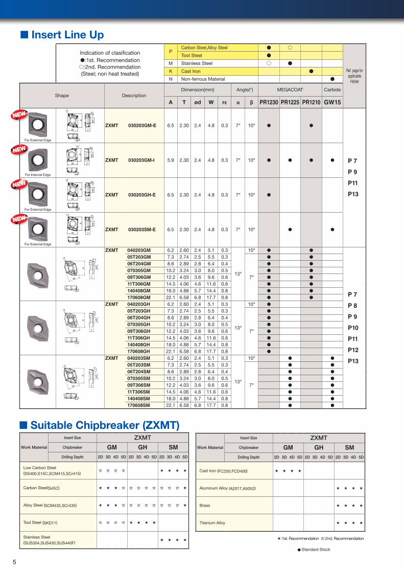
■ Insert Line Up
Indication of clasification●:1st. Recommendation
:2nd. Recommendation (Steel; non heat treated)
PCarbon Steel,Alloy Steel ●
Ref. page for applicable
Holder
Tool Steel ●
M Stainless Steel ●
K Cast Iron ●
N Non-ferrous Material ●
Shape DescriptionDimension(mm) Angle(°) MEGACOAT Carbide
A T ød W rε α β PR1230 PR1225 PR1210 GW15
For External Edge
A
W T
rε
α
β
ød
ZXMT 030203GM-E 6.5 2.30 2.4 4.8 0.3 7° 10° ● ●
P 7
P 9
P11
P13
For Internal Edge
A
W
β
rε
T
ødα
ZXMT 030203GM-I 5.9 2.30 2.4 4.8 0.3 7° 10° ● ● ● ●
For External Edge
A
W T
rε
α
β
ød
ZXMT 030203GH-E 6.5 2.30 2.4 4.8 0.3 7° 10° ●
For External Edge
W
A
rε α
T
ød
β
ZXMT 030203SM-E 6.5 2.30 2.4 4.8 0.3 7° 10° ● ●
A ød
W
rε
T
β
α
ZXMT 040203GM 6.2 2.60 2.4 5.1 0.3
13°
10° ● ●
P 7
P 8
P 9
P10
P11
P12
P13
05T203GM 7.3 2.74 2.5 5.5 0.3
7°
● ●
06T204GM 8.6 2.89 2.8 6.4 0.4 ● ●
070305GM 10.2 3.24 3.0 8.0 0.5 ● ●
09T306GM 12.2 4.03 3.6 9.6 0.6 ● ●
11T306GM 14.5 4.06 4.6 11.6 0.6 ● ●
140408GM 18.0 4.88 5.7 14.4 0.8 ● ●
170608GM 22.1 6.58 6.8 17.7 0.8 ● ●
T
A
W
rε
α
β
ød
ZXMT 040203GH 6.2 2.60 2.4 5.1 0.3
13°
10° ●
05T203GH 7.3 2.74 2.5 5.5 0.3
7°
●
06T204GH 8.6 2.89 2.8 6.4 0.4 ●
070305GH 10.2 3.24 3.0 8.0 0.5 ●
09T306GH 12.2 4.03 3.6 9.6 0.6 ●
11T306GH 14.5 4.06 4.6 11.6 0.6 ●
140408GH 18.0 4.88 5.7 14.4 0.8 ●
170608GH 22.1 6.58 6.8 17.7 0.8 ●
A
W T
rε
α
β
ød
ZXMT 040203SM 6.2 2.60 2.4 5.1 0.3
13°
10° ● ●
05T203SM 7.3 2.74 2.5 5.5 0.3
7°
● ●
06T204SM 8.6 2.89 2.8 6.4 0.4 ● ●
070305SM 10.2 3.24 3.0 8.0 0.5 ● ●
09T306SM 12.2 4.03 3.6 9.6 0.6 ● ●
11T306SM 14.5 4.06 4.6 11.6 0.6 ● ●
140408SM 18.0 4.88 5.7 14.4 0.8 ● ●
170608SM 22.1 6.58 6.8 17.7 0.8 ● ●
■ Suitable Chipbreaker (ZXMT)
Work Material
Insert Size ZXMTChipbreaker GM GH SM
Drilling Depth 2D 3D 4D 5D 2D 3D 4D 5D 2D 3D 4D 5D
Low Carbon Steel(SS400,S15C,SCM415,SCr415)
★ ★ ★ ★
Carbon Steel(S45C) ★ ★ ★ ★
Alloy Steel (SCM435,SCr435) ★ ★ ★ ★
Tool Steel (SKD11) ★ ★ ★ ★
Stainless Steel(SUS304,SUS430,SUS440F)
★ ★ ★ ★
Work Material
Insert Size ZXMTChipbreaker GM GH SM
Drilling Depth 2D 3D 4D 5D 2D 3D 4D 5D 2D 3D 4D 5D
Cast Iron (FC250,FCD400) ★ ★ ★ ★
Aluminum Alloy (A2017,A5052) ★ ★ ★ ★
Brass ★ ★ ★ ★
Titanium Alloy ★ ★ ★ ★
●:Standard Stock
NEW
NEW
NEW
NEW
★:1st. Recommendation :2nd. Recommendation
5
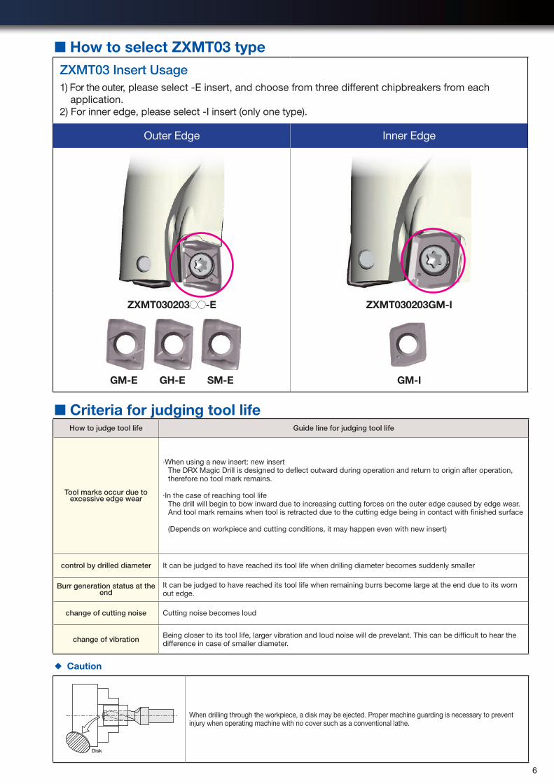
■ How to select ZXMT03 typeZXMT03 Insert Usage1) For the outer, please select -E insert, and choose from three different chipbreakers from each
application.2) For inner edge, please select -I insert (only one type).
Outer Edge Inner Edge
ZXMT030203 -E
GM-E GH-E SM-E
ZXMT030203GM-I
GM-I
■ Criteria for judging tool lifeHow to judge tool life Guide line for judging tool life
Tool marks occur due to excessive edge wear
·When using a new insert: new insertThe DRX Magic Drill is designed to deflect outward during operation and return to origin after operation, therefore no tool mark remains.
·In the case of reaching tool lifeThe drill will begin to bow inward due to increasing cutting forces on the outer edge caused by edge wear. And tool mark remains when tool is retracted due to the cutting edge being in contact with finished surface
(Depends on workpiece and cutting conditions, it may happen even with new insert)
control by drilled diameter It can be judged to have reached its tool life when drilling diameter becomes suddenly smaller
Burr generation status at the end
It can be judged to have reached its tool life when remaining burrs become large at the end due to its worn out edge.
change of cutting noise Cutting noise becomes loud
change of vibration Being closer to its tool life, larger vibration and loud noise will de prevelant. This can be difficult to hear the difference in case of smaller diameter.
◆ Caution
Disk
When drilling through the workpiece, a disk may be ejected. Proper machine guarding is necessary to prevent injury when operating machine with no cover such as a conventional lathe.
●:Standard Stock
6
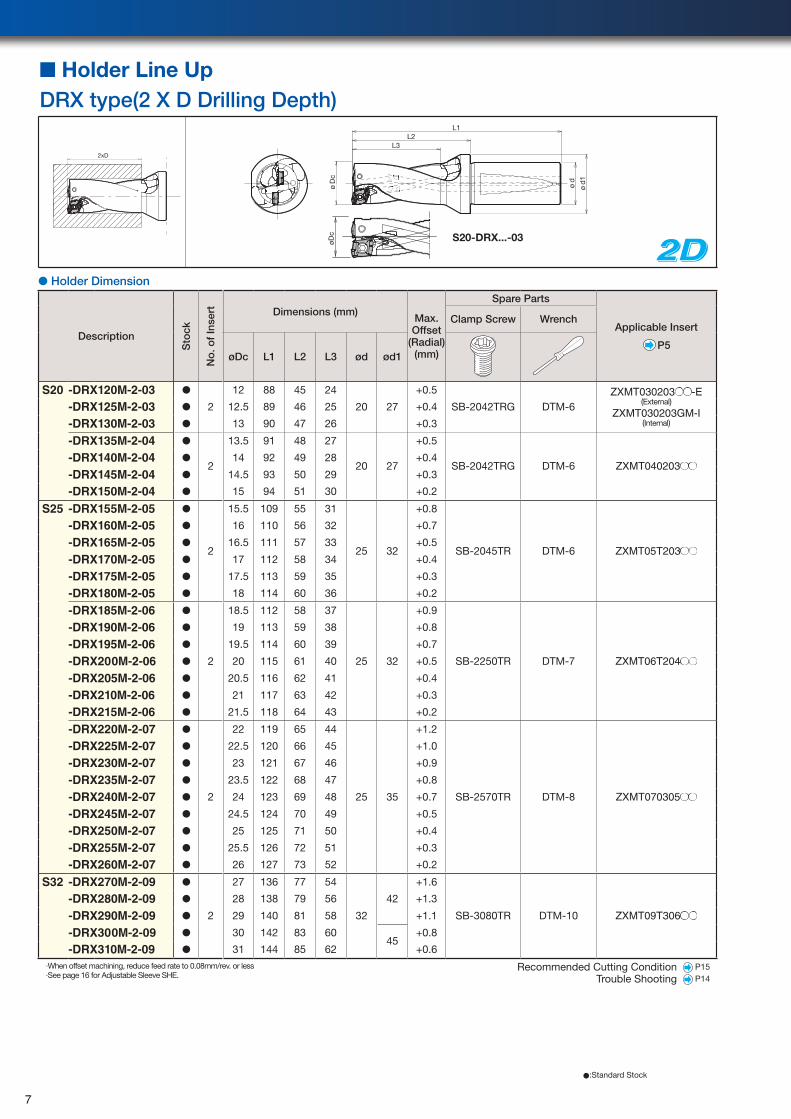
●:Standard Stock
2D2D2D● Holder Dimension
Description
Sto
ck
No
. of
Inse
rt Dimensions (mm)Max. Offset
(Radial)(mm)
Spare Parts
Applicable Insert
P5
Clamp Screw Wrench
øDc L1 L2 L3 ød ød1
S20 -DRX120M-2-03 ●
2
12 88 45 24
20 27
+0.5
SB-2042TRG DTM-6ZXMT030203●●-E
(External)ZXMT030203GM-I
(Internal)
-DRX125M-2-03 ● 12.5 89 46 25 +0.4
-DRX130M-2-03 ● 13 90 47 26 +0.3
-DRX135M-2-04 ●
2
13.5 91 48 27
20 27
+0.5
SB-2042TRG DTM-6 ZXMT040203●●-DRX140M-2-04 ● 14 92 49 28 +0.4
-DRX145M-2-04 ● 14.5 93 50 29 +0.3
-DRX150M-2-04 ● 15 94 51 30 +0.2
S25 -DRX155M-2-05 ●
2
15.5 109 55 31
25 32
+0.8
SB-2045TR DTM-6 ZXMT05T203●●
-DRX160M-2-05 ● 16 110 56 32 +0.7
-DRX165M-2-05 ● 16.5 111 57 33 +0.5
-DRX170M-2-05 ● 17 112 58 34 +0.4
-DRX175M-2-05 ● 17.5 113 59 35 +0.3
-DRX180M-2-05 ● 18 114 60 36 +0.2
-DRX185M-2-06 ●
2
18.5 112 58 37 +0.9
-DRX190M-2-06 ● 19 113 59 38 +0.8
-DRX195M-2-06 ● 19.5 114 60 39 +0.7
-DRX200M-2-06 ● 20 115 61 40 25 32 +0.5 SB-2250TR DTM-7 ZXMT06T204●●
-DRX205M-2-06 ● 20.5 116 62 41 +0.4
-DRX210M-2-06 ● 21 117 63 42 +0.3
-DRX215M-2-06 ● 21.5 118 64 43 +0.2
-DRX220M-2-07 ●
2
22 119 65 44 +1.2
-DRX225M-2-07 ● 22.5 120 66 45 +1.0
-DRX230M-2-07 ● 23 121 67 46 +0.9
-DRX235M-2-07 ● 23.5 122 68 47 +0.8
-DRX240M-2-07 ● 24 123 69 48 25 35 +0.7 SB-2570TR DTM-8 ZXMT070305●●
-DRX245M-2-07 ● 24.5 124 70 49 +0.5
-DRX250M-2-07 ● 25 125 71 50 +0.4
-DRX255M-2-07 ● 25.5 126 72 51 +0.3
-DRX260M-2-07 ● 26 127 73 52 +0.2
S32 -DRX270M-2-09 ●
2
27 136 77 54 +1.6
-DRX280M-2-09 ● 28 138 79 56 42 +1.3
-DRX290M-2-09 ● 29 140 81 58 32 +1.1 SB-3080TR DTM-10 ZXMT09T306●●
-DRX300M-2-09 ● 30 142 83 6045
+0.8
-DRX310M-2-09 ● 31 144 85 62 +0.6
·When offset machining, reduce feed rate to 0.08mm/rev. or less·See page 16 for Adjustable Sleeve SHE.
2xD
ød
1
ød
øD
c
L3L2
L1
øDc
2xD
ød
1
ød
øD
c
L3L2
L1
øDc
■ Holder Line UpDRX type(2 X D Drilling Depth)
Recommended Cutting Condition P15
Trouble Shooting P14
S20-DRX...-03
7
Recommended Cutting Condition P15
Trouble Shooting P14
Description
Sto
ck
No
. of
Inse
rt Dimensions (mm)Max. Offset
(Radial)(mm)
Spare Parts
Applicable Insert
P5
Clamp Screw Wrench
øDc L1 L2 L3 ød ød1
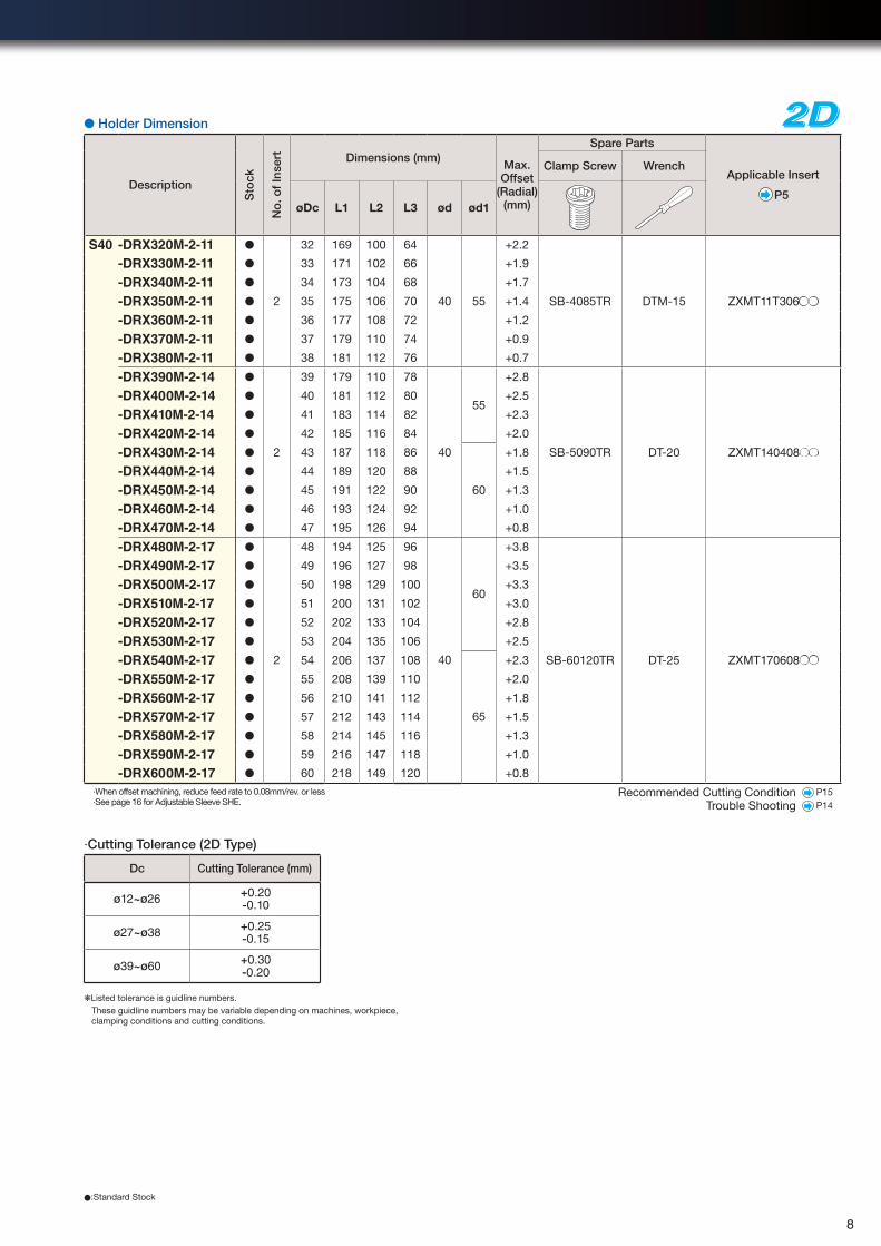
S40 -DRX320M-2-11 ● 32 169 100 64 +2.2
SB-4085TR DTM-15 ZXMT11T306●●
-DRX330M-2-11 ● 33 171 102 66 +1.9
-DRX340M-2-11 ● 34 173 104 68 +1.7
-DRX350M-2-11 ● 2 35 175 106 70 40 55 +1.4
-DRX360M-2-11 ● 36 177 108 72 +1.2
-DRX370M-2-11 ● 37 179 110 74 +0.9
-DRX380M-2-11 ● 38 181 112 76 +0.7
-DRX390M-2-14 ●
2
39 179 110 78
40
55
+2.8
SB-5090TR DT-20 ZXMT140408●●
-DRX400M-2-14 ● 40 181 112 80 +2.5
-DRX410M-2-14 ● 41 183 114 82 +2.3
-DRX420M-2-14 ● 42 185 116 84 +2.0
-DRX430M-2-14 ● 43 187 118 86
60
+1.8
-DRX440M-2-14 ● 44 189 120 88 +1.5
-DRX450M-2-14 ● 45 191 122 90 +1.3
-DRX460M-2-14 ● 46 193 124 92 +1.0
-DRX470M-2-14 ● 47 195 126 94 +0.8
-DRX480M-2-17 ●
2
48 194 125 96
40
60
+3.8
SB-60120TR DT-25 ZXMT170608●●
-DRX490M-2-17 ● 49 196 127 98 +3.5
-DRX500M-2-17 ● 50 198 129 100 +3.3
-DRX510M-2-17 ● 51 200 131 102 +3.0
-DRX520M-2-17 ● 52 202 133 104 +2.8
-DRX530M-2-17 ● 53 204 135 106 +2.5
-DRX540M-2-17 ● 54 206 137 108
65
+2.3
-DRX550M-2-17 ● 55 208 139 110 +2.0
-DRX560M-2-17 ● 56 210 141 112 +1.8
-DRX570M-2-17 ● 57 212 143 114 +1.5
-DRX580M-2-17 ● 58 214 145 116 +1.3
-DRX590M-2-17 ● 59 216 147 118 +1.0
-DRX600M-2-17 ● 60 218 149 120 +0.8
·When offset machining, reduce feed rate to 0.08mm/rev. or less·See page 16 for Adjustable Sleeve SHE.
2D2D2D
●:Standard Stock
● Holder Dimension
·Cutting Tolerance (2D Type)
❋Listed tolerance is guidline numbers.These guidline numbers may be variable depending on machines, workpiece, clamping conditions and cutting conditions.
Dc Cutting Tolerance (mm)
ø12~ø26 +0.20-0.10
ø27~ø38 +0.25-0.15
ø39~ø60 +0.30-0.20
8
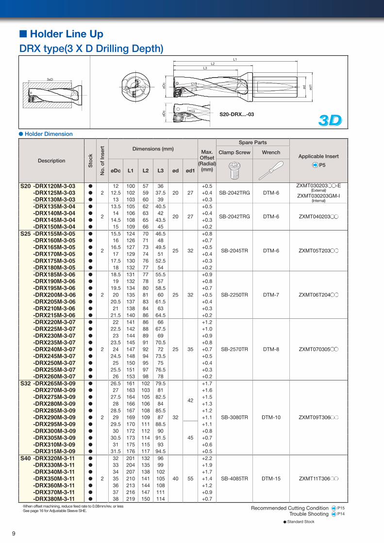
● Holder Dimension
Description
Sto
ck
No
. of
Inse
rt Dimensions (mm)Max. Offset
(Radial)(mm)
Spare Parts
Applicable Insert
P5
Clamp Screw Wrench
øDc L1 L2 L3 ød ød1
S20 -DRX120M-3-03 ●
212 100 57 36
20 27+0.5
SB-2042TRG DTM-6ZXMT030203●●-E
(External)ZXMT030203GM-I
(Internal)
-DRX125M-3-03 ● 12.5 102 59 37.5 +0.4-DRX130M-3-03 ● 13 103 60 39 +0.3-DRX135M-3-04 ●
2
13.5 105 62 40.5
20 27
+0.5
SB-2042TRG DTM-6 ZXMT040203●●-DRX140M-3-04 ● 14 106 63 42 +0.4-DRX145M-3-04 ● 14.5 108 65 43.5 +0.3-DRX150M-3-04 ● 15 109 66 45 +0.2
S25 -DRX155M-3-05 ●
2
15.5 124 70 46.5
25 32
+0.8
SB-2045TR DTM-6 ZXMT05T203●●
-DRX160M-3-05 ● 16 126 71 48 +0.7-DRX165M-3-05 ● 16.5 127 73 49.5 +0.5-DRX170M-3-05 ● 17 129 74 51 +0.4-DRX175M-3-05 ● 17.5 130 76 52.5 +0.3-DRX180M-3-05 ● 18 132 77 54 +0.2-DRX185M-3-06 ●
2
18.5 131 77 55.5
25 32
+0.9
SB-2250TR DTM-7 ZXMT06T204●●
-DRX190M-3-06 ● 19 132 78 57 +0.8-DRX195M-3-06 ● 19.5 134 80 58.5 +0.7-DRX200M-3-06 ● 20 135 81 60 +0.5-DRX205M-3-06 ● 20.5 137 83 61.5 +0.4-DRX210M-3-06 ● 21 138 84 63 +0.3-DRX215M-3-06 ● 21.5 140 86 64.5 +0.2-DRX220M-3-07 ●
2
22 141 86 66
25 35
+1.2
SB-2570TR DTM-8 ZXMT070305●●
-DRX225M-3-07 ● 22.5 142 88 67.5 +1.0-DRX230M-3-07 ● 23 144 89 69 +0.9-DRX235M-3-07 ● 23.5 145 91 70.5 +0.8-DRX240M-3-07 ● 24 147 92 72 +0.7-DRX245M-3-07 ● 24.5 148 94 73.5 +0.5-DRX250M-3-07 ● 25 150 95 75 +0.4-DRX255M-3-07 ● 25.5 151 97 76.5 +0.3-DRX260M-3-07 ● 26 153 98 78 +0.2
S32 -DRX265M-3-09 ●
2
26.5 161 102 79.5
32
42
+1.7
SB-3080TR DTM-10 ZXMT09T306●●
-DRX270M-3-09 ● 27 163 103 81 +1.6-DRX275M-3-09 ● 27.5 164 105 82.5 +1.5-DRX280M-3-09 ● 28 166 106 84 +1.3-DRX285M-3-09 ● 28.5 167 108 85.5 +1.2-DRX290M-3-09 ● 29 169 109 87 +1.1-DRX295M-3-09 ● 29.5 170 111 88.5
45
+1.1-DRX300M-3-09 ● 30 172 112 90 +0.8-DRX305M-3-09 ● 30.5 173 114 91.5 +0.7-DRX310M-3-09 ● 31 175 115 93 +0.6-DRX315M-3-09 ● 31.5 176 117 94.5 +0.5
S40 -DRX320M-3-11 ●
2
32 201 132 96
40 55
+2.2
SB-4085TR DTM-15 ZXMT11T306●●
-DRX330M-3-11 ● 33 204 135 99 +1.9-DRX340M-3-11 ● 34 207 138 102 +1.7-DRX350M-3-11 ● 35 210 141 105 +1.4-DRX360M-3-11 ● 36 213 144 108 +1.2-DRX370M-3-11 ● 37 216 147 111 +0.9-DRX380M-3-11 ● 38 219 150 114 +0.7
·When offset machining, reduce feed rate to 0.08mm/rev. or less·See page 16 for Adjustable Sleeve SHE.
3D3D3D
3xD
øDc
L3L2
L1
ød ød1
øDc
■ Holder Line UpDRX type(3 X D Drilling Depth)
●:Standard Stock
Recommended Cutting Condition P15
Trouble Shooting P14
S20-DRX...-03
9
●:Standard Stock
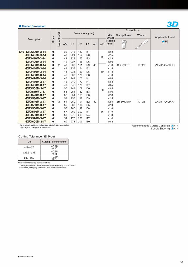
● Holder Dimension
Description
Sto
ck
No
. of
Inse
rt Dimensions (mm)Max. Offset
(Radial)(mm)
Spare Parts
Applicable Insert
P5
Clamp Screw Wrench
øDc L1 L2 L3 ød ød1
S40 -DRX390M-3-14 ●
2
39 218 149 117
40
55
+2.8
SB-5090TR DT-20 ZXMT140408●●
-DRX400M-3-14 ● 40 221 152 120 +2.5-DRX410M-3-14 ● 41 224 155 123 +2.3-DRX420M-3-14 ● 42 227 158 126 +2.0-DRX430M-3-14 ● 43 230 161 129
60
+1.8-DRX440M-3-14 ● 44 233 164 132 +1.5-DRX450M-3-14 ● 45 236 167 135 +1.3-DRX460M-3-14 ● 46 239 170 138 +1.0-DRX470M-3-14 ● 47 242 173 141 +0.8-DRX480M-3-17 ●
2
48 242 173 144
40
60
+3.8
SB-60120TR DT-25 ZXMT170608●●
-DRX490M-3-17 ● 49 245 176 147 +3.5-DRX500M-3-17 ● 50 248 179 150 +3.3-DRX510M-3-17 ● 51 251 182 153 +3.0-DRX520M-3-17 ● 52 254 185 156 +2.8-DRX530M-3-17 ● 53 257 188 159 +2.5-DRX540M-3-17 ● 54 260 191 162
65
+2.3-DRX550M-3-17 ● 55 263 194 165 +2.0-DRX560M-3-17 ● 56 266 197 168 +1.8-DRX570M-3-17 ● 57 269 200 171 +1.5-DRX580M-3-17 ● 58 272 203 174 +1.3-DRX590M-3-17 ● 59 275 206 177 +1.0-DRX600M-3-17 ● 60 278 209 180 +0.8
·When offset machining, reduce feed rate to 0.08mm/rev. or less·See page 16 for Adjustable Sleeve SHE.
3D3D3D
Recommended Cutting Condition P15
Trouble Shooting P14
·Cutting Tolerance (3D Type)
❋Listed tolerance is guidline numbers.These guidline numbers may be variable depending on machines, workpiece, clamping conditions and cutting conditions.
Dc Cutting Tolerance (mm)
ø12~ø26 +0.20-0.10
ø26.5~ø38 +0.25-0.15
ø39~ø60 +0.30-0.20
10
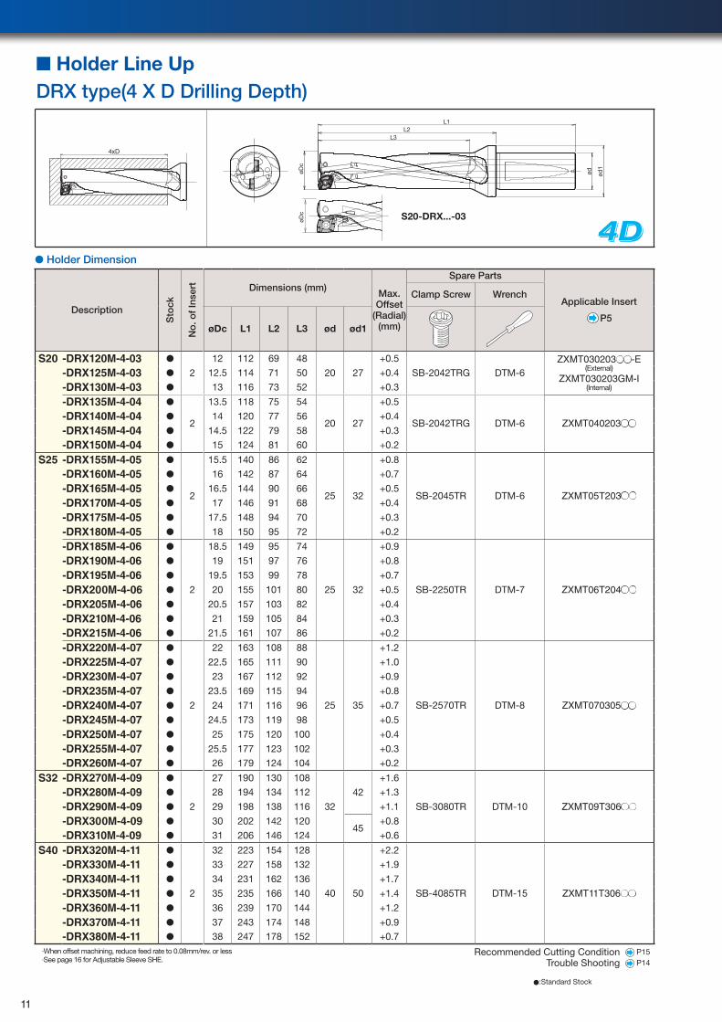
4D4D4D● Holder Dimension
Description
Sto
ck
No
. of
Inse
rt Dimensions (mm)Max. Offset
(Radial)(mm)
Spare Parts
Applicable Insert
P5
Clamp Screw Wrench
øDc L1 L2 L3 ød ød1
S20 -DRX120M-4-03 ●
2
12 112 69 48
20 27
+0.5
SB-2042TRG DTM-6ZXMT030203●●-E
(External)ZXMT030203GM-I
(Internal)
-DRX125M-4-03 ● 12.5 114 71 50 +0.4
-DRX130M-4-03 ● 13 116 73 52 +0.3
-DRX135M-4-04 ●
2
13.5 118 75 54
20 27
+0.5
SB-2042TRG DTM-6 ZXMT040203●●-DRX140M-4-04 ● 14 120 77 56 +0.4
-DRX145M-4-04 ● 14.5 122 79 58 +0.3
-DRX150M-4-04 ● 15 124 81 60 +0.2
S25 -DRX155M-4-05 ●
2
15.5 140 86 62
25 32
+0.8
SB-2045TR DTM-6 ZXMT05T203●●
-DRX160M-4-05 ● 16 142 87 64 +0.7
-DRX165M-4-05 ● 16.5 144 90 66 +0.5
-DRX170M-4-05 ● 17 146 91 68 +0.4
-DRX175M-4-05 ● 17.5 148 94 70 +0.3
-DRX180M-4-05 ● 18 150 95 72 +0.2
-DRX185M-4-06 ●
2
18.5 149 95 74
25 32
+0.9
SB-2250TR DTM-7 ZXMT06T204●●
-DRX190M-4-06 ● 19 151 97 76 +0.8
-DRX195M-4-06 ● 19.5 153 99 78 +0.7
-DRX200M-4-06 ● 20 155 101 80 +0.5
-DRX205M-4-06 ● 20.5 157 103 82 +0.4
-DRX210M-4-06 ● 21 159 105 84 +0.3
-DRX215M-4-06 ● 21.5 161 107 86 +0.2
-DRX220M-4-07 ●
2
22 163 108 88
25 35
+1.2
SB-2570TR DTM-8 ZXMT070305●●
-DRX225M-4-07 ● 22.5 165 111 90 +1.0
-DRX230M-4-07 ● 23 167 112 92 +0.9
-DRX235M-4-07 ● 23.5 169 115 94 +0.8
-DRX240M-4-07 ● 24 171 116 96 +0.7
-DRX245M-4-07 ● 24.5 173 119 98 +0.5
-DRX250M-4-07 ● 25 175 120 100 +0.4
-DRX255M-4-07 ● 25.5 177 123 102 +0.3
-DRX260M-4-07 ● 26 179 124 104 +0.2
S32 -DRX270M-4-09 ●
2
27 190 130 108
32
42
+1.6
SB-3080TR DTM-10 ZXMT09T306●●
-DRX280M-4-09 ● 28 194 134 112 +1.3
-DRX290M-4-09 ● 29 198 138 116 +1.1
-DRX300M-4-09 ● 30 202 142 12045
+0.8
-DRX310M-4-09 ● 31 206 146 124 +0.6
S40 -DRX320M-4-11 ●
2
32 223 154 128
40 50
+2.2
SB-4085TR DTM-15 ZXMT11T306●●
-DRX330M-4-11 ● 33 227 158 132 +1.9
-DRX340M-4-11 ● 34 231 162 136 +1.7
-DRX350M-4-11 ● 35 235 166 140 +1.4
-DRX360M-4-11 ● 36 239 170 144 +1.2
-DRX370M-4-11 ● 37 243 174 148 +0.9
-DRX380M-4-11 ● 38 247 178 152 +0.7·When offset machining, reduce feed rate to 0.08mm/rev. or less·See page 16 for Adjustable Sleeve SHE.
Recommended Cutting Condition P15
Trouble Shooting P14
øDc
L3L2
L1
ød ød1
øDc
4xD
■ Holder Line UpDRX type(4 X D Drilling Depth)
●:Standard Stock
S20-DRX...-03
11
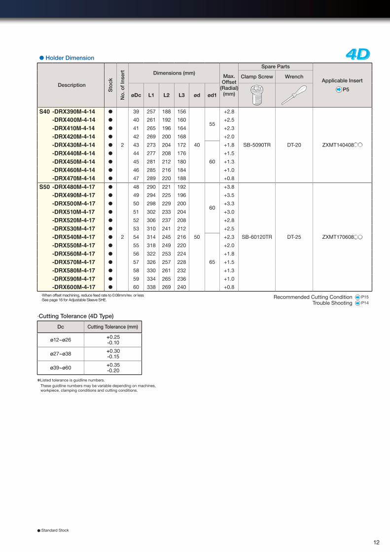
4D4D4D● Holder Dimension
Description
Sto
ck
No
. of
Inse
rt Dimensions (mm)Max. Offset
(Radial)(mm)
Spare Parts
Applicable Insert
P5
Clamp Screw Wrench
øDc L1 L2 L3 ød ød1
S40 -DRX390M-4-14 ●
2
39 257 188 156
40
55
+2.8
SB-5090TR DT-20 ZXMT140408●●
-DRX400M-4-14 ● 40 261 192 160 +2.5
-DRX410M-4-14 ● 41 265 196 164 +2.3
-DRX420M-4-14 ● 42 269 200 168 +2.0
-DRX430M-4-14 ● 43 273 204 172
60
+1.8
-DRX440M-4-14 ● 44 277 208 176 +1.5
-DRX450M-4-14 ● 45 281 212 180 +1.3
-DRX460M-4-14 ● 46 285 216 184 +1.0
-DRX470M-4-14 ● 47 289 220 188 +0.8
S50 -DRX480M-4-17 ●
2
48 290 221 192
50
60
+3.8
SB-60120TR DT-25 ZXMT170608●●
-DRX490M-4-17 ● 49 294 225 196 +3.5
-DRX500M-4-17 ● 50 298 229 200 +3.3
-DRX510M-4-17 ● 51 302 233 204 +3.0
-DRX520M-4-17 ● 52 306 237 208 +2.8
-DRX530M-4-17 ● 53 310 241 212 +2.5
-DRX540M-4-17 ● 54 314 245 216
65
+2.3
-DRX550M-4-17 ● 55 318 249 220 +2.0
-DRX560M-4-17 ● 56 322 253 224 +1.8
-DRX570M-4-17 ● 57 326 257 228 +1.5
-DRX580M-4-17 ● 58 330 261 232 +1.3
-DRX590M-4-17 ● 59 334 265 236 +1.0
-DRX600M-4-17 ● 60 338 269 240 +0.8
·When offset machining, reduce feed rate to 0.08mm/rev. or less·See page 16 for Adjustable Sleeve SHE.
Recommended Cutting Condition P15
Trouble Shooting P14
·Cutting Tolerance (4D Type)
❋Listed tolerance is guidline numbers.These guidline numbers may be variable depending on machines, workpiece, clamping conditions and cutting conditions.
Dc Cutting Tolerance (mm)
ø12~ø26 +0.25-0.10
ø27~ø38 +0.30-0.15
ø39~ø60 +0.35-0.20
●:Standard Stock
●:Standard Stock
12
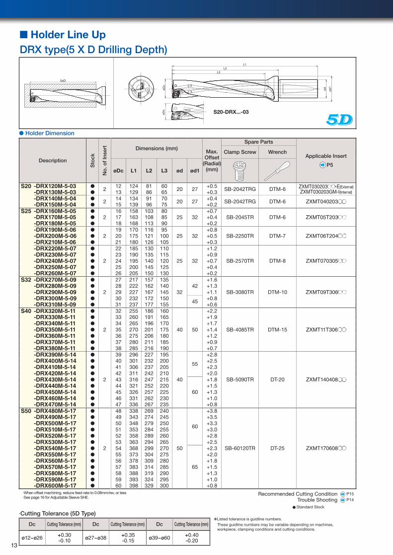
■ Holder Line UpDRX type(5 X D Drilling Depth)
● Holder Dimension
Description
Sto
ck
No
. of
Inse
rt Dimensions (mm)Max. Offset
(Radial)(mm)
Spare Parts
Applicable Insert
P5
Clamp Screw Wrench
øDc L1 L2 L3 ød ød1
S20 -DRX120M-5-03 ● 2 12 124 81 60 20 27 +0.5 SB-2042TRG DTM-6 ZXMT030203●●-E(External)ZXMT030203GM-I(Internal)-DRX130M-5-03 ● 13 129 86 65 +0.3
-DRX140M-5-04 ● 2 14 134 91 70 20 27 +0.4 SB-2042TRG DTM-6 ZXMT040203●●-DRX150M-5-04 ● 15 139 96 75 +0.2S25 -DRX160M-5-05 ●
216 158 103 80
25 32+0.7
SB-2045TR DTM-6 ZXMT05T203●●-DRX170M-5-05 ● 17 163 108 85 +0.4-DRX180M-5-05 ● 18 168 113 90 +0.2-DRX190M-5-06 ●
219 170 116 95
25 32+0.8
SB-2250TR DTM-7 ZXMT06T204●●-DRX200M-5-06 ● 20 175 121 100 +0.5-DRX210M-5-06 ● 21 180 126 105 +0.3-DRX220M-5-07 ●
2
22 185 130 110
25 32
+1.2
SB-2570TR DTM-8 ZXMT070305●●-DRX230M-5-07 ● 23 190 135 115 +0.9-DRX240M-5-07 ● 24 195 140 120 +0.7-DRX250M-5-07 ● 25 200 145 125 +0.4-DRX260M-5-07 ● 26 205 150 130 +0.2
S32 -DRX270M-5-09 ●
2
27 217 157 135 +1.6
SB-3080TR DTM-10 ZXMT09T306●●-DRX280M-5-09 ● 28 222 162 140 42 +1.3-DRX290M-5-09 ● 29 227 167 145 32 +1.1-DRX300M-5-09 ● 30 232 172 150 45 +0.8-DRX310M-5-09 ● 31 237 177 155 +0.6
S40 -DRX320M-5-11 ●
2
32 255 186 160
40 50
+2.2
SB-4085TR DTM-15 ZXMT11T306●●
-DRX330M-5-11 ● 33 260 191 165 +1.9-DRX340M-5-11 ● 34 265 196 170 +1.7-DRX350M-5-11 ● 35 270 201 175 +1.4-DRX360M-5-11 ● 36 275 206 180 +1.2-DRX370M-5-11 ● 37 280 211 185 +0.9-DRX380M-5-11 ● 38 285 216 190 +0.7-DRX390M-5-14 ●
2
39 296 227 195
40
55
+2.8
SB-5090TR DT-20 ZXMT140408●●
-DRX400M-5-14 ● 40 301 232 200 +2.5-DRX410M-5-14 ● 41 306 237 205 +2.3-DRX420M-5-14 ● 42 311 242 210 +2.0-DRX430M-5-14 ● 43 316 247 215
60
+1.8-DRX440M-5-14 ● 44 321 252 220 +1.5-DRX450M-5-14 ● 45 326 257 225 +1.3-DRX460M-5-14 ● 46 331 262 230 +1.0-DRX470M-5-14 ● 47 336 267 235 +0.8
S50 -DRX480M-5-17 ●
2
48 338 269 240
50
60
+3.8
SB-60120TR DT-25 ZXMT170608●●
-DRX490M-5-17 ● 49 343 274 245 +3.5-DRX500M-5-17 ● 50 348 279 250 +3.3-DRX510M-5-17 ● 51 353 284 255 +3.0-DRX520M-5-17 ● 52 358 289 260 +2.8-DRX530M-5-17 ● 53 363 294 265 +2.5-DRX540M-5-17 ● 54 368 299 270
65
+2.3-DRX550M-5-17 ● 55 373 304 275 +2.0-DRX560M-5-17 ● 56 378 309 280 +1.8-DRX570M-5-17 ● 57 383 314 285 +1.5-DRX580M-5-17 ● 58 388 319 290 +1.3-DRX590M-5-17 ● 59 393 324 295 +1.0-DRX600M-5-17 ● 60 398 329 300 +0.8
·When offset machining, reduce feed rate to 0.08mm/rev. or less·See page 16 for Adjustable Sleeve SHE.
Recommended Cutting Condition P15
Trouble Shooting P14
5xD
øDc
L3L2
L1
ød ød1
øDc
·Cutting Tolerance (5D Type)
Dc Cutting Tolerance (mm) Dc Cutting Tolerance (mm) Dc Cutting Tolerance (mm)
ø12~ø26 +0.30-0.10 ø27~ø38 +0.35
-0.15 ø39~ø60 +0.40-0.20
❋Listed tolerance is guidline numbers.These guidline numbers may be variable depending on machines, workpiece, clamping conditions and cutting conditions.
●:Standard Stock
S20-DRX...-03
13
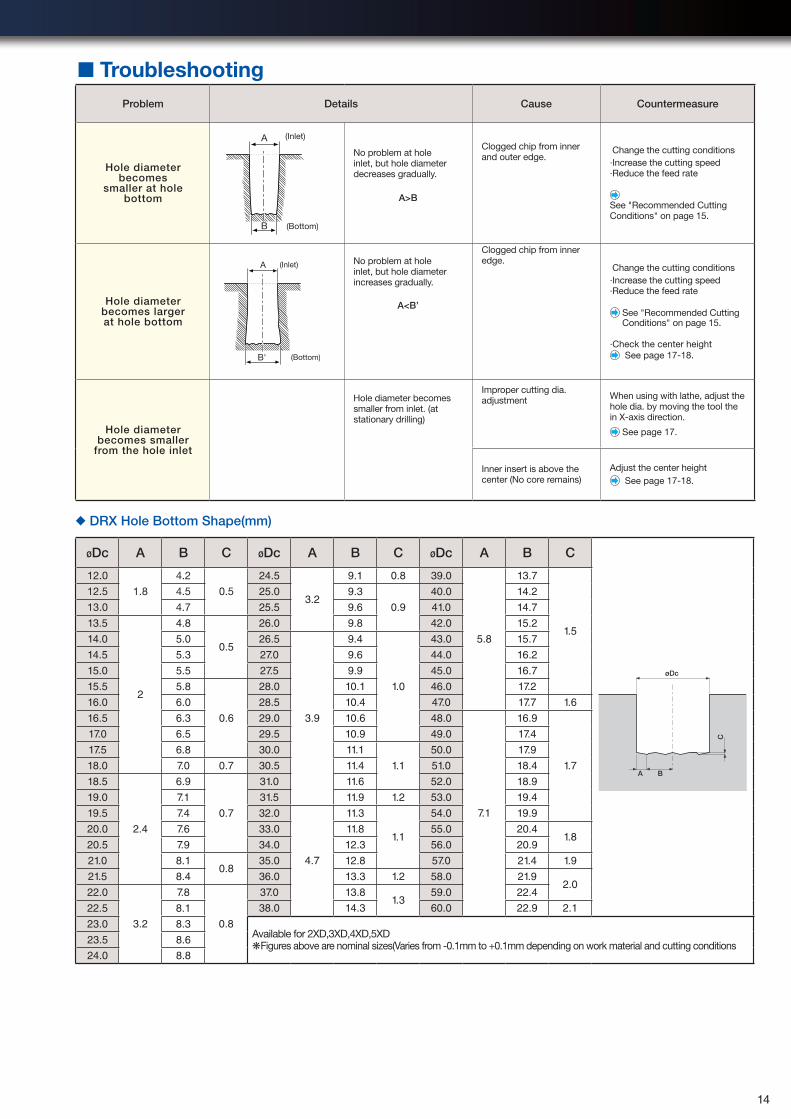
◆ DRX Hole Bottom Shape(mm)
øDc A B C øDc A B C øDc A B C
øDc
A B
C
12.0
1.8
4.2
0.5
24.5
3.2
9.1 0.8 39.0
5.8
13.7
1.5
12.5 4.5 25.0 9.3
0.9
40.0 14.2
13.0 4.7 25.5 9.6 41.0 14.7
13.5
2
4.8
0.5
26.0 9.8 42.0 15.2
14.0 5.0 26.5
3.9
9.4
1.0
43.0 15.7
14.5 5.3 27.0 9.6 44.0 16.2
15.0 5.5 27.5 9.9 45.0 16.7
15.5 5.8
0.6
28.0 10.1 46.0 17.2
16.0 6.0 28.5 10.4 47.0 17.7 1.6
16.5 6.3 29.0 10.6 48.0
7.1
16.9
1.7
17.0 6.5 29.5 10.9 49.0 17.4
17.5 6.8 30.0 11.1
1.1
50.0 17.9
18.0 7.0 0.7 30.5 11.4 51.0 18.4
18.5
2.4
6.9
0.7
31.0 11.6 52.0 18.9
19.0 7.1 31.5 11.9 1.2 53.0 19.4
19.5 7.4 32.0
4.7
11.3
1.1
54.0 19.9
20.0 7.6 33.0 11.8 55.0 20.41.8
20.5 7.9 34.0 12.3 56.0 20.9
21.0 8.10.8
35.0 12.8 57.0 21.4 1.9
21.5 8.4 36.0 13.3 1.2 58.0 21.92.0
22.0
3.2
7.8
0.8
37.0 13.81.3
59.0 22.4
22.5 8.1 38.0 14.3 60.0 22.9 2.1
23.0 8.3Available for 2XD,3XD,4XD,5XD❋Figures above are nominal sizes(Varies from -0.1mm to +0.1mm depending on work material and cutting conditions23.5 8.6
24.0 8.8
●:Standard Stock
■ TroubleshootingProblem Details Cause Countermeasure
Hole diameter becomes
smaller at hole bottom
A
B (Bottom)
(Inlet)
No problem at hole inlet, but hole diameter decreases gradually.
A>B
Clogged chip from inner and outer edge.
Change the cutting conditions·Increase the cutting speed·Reduce the feed rate
See "Recommended Cutting Conditions" on page 15.
Hole diameter becomes larger at hole bottom
B' (Bottom)
(Inlet)A No problem at hole inlet, but hole diameter increases gradually.
A<B’
Clogged chip from inner edge.
Change the cutting conditions·Increase the cutting speed·Reduce the feed rate
See "Recommended Cutting Conditions" on page 15.
·Check the center height See page 17-18.
Hole diameter becomes smaller
from the hole inlet
Hole diameter becomes smaller from inlet. (at stationary drilling)
Improper cutting dia. adjustment When using with lathe, adjust the
hole dia. by moving the tool the in X-axis direction.
See page 17.
Inner insert is above the center (No core remains)
Adjust the center height See page 17-18.
14
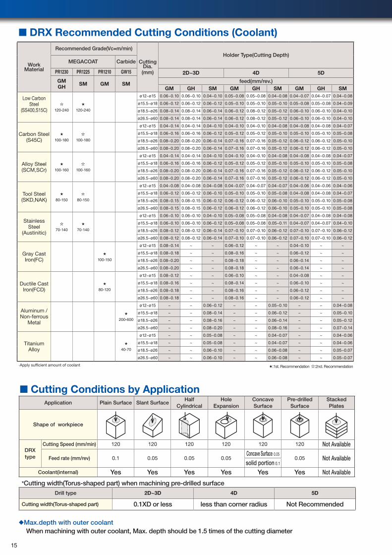
Work Material
Recommended Grade(Vc=m/min)
Cutting Dia. (mm)
Holder Type(Cutting Depth)MEGACOAT Carbide
PR1230 PR1225 PR1210 GW15 2D~3D 4D 5D
GMGH SM GM SM feed(mm/rev.)
GM GH SM GM GH SM GM GH SM
Low Carbon Steel
(SS400,S15C) 120-240
★
120-240
ø12~ø15 0.06~0.10 0.06~0.10 0.04~0.10 0.05~0.08 0.05~0.08 0.04~0.08 0.04~0.07 0.04~0.07 0.04~0.08
ø15.5~ø18 0.06~0.12 0.06~0.12 0.06~0.12 0.05~0.10 0.05~0.10 0.05~0.10 0.05~0.08 0.05~0.08 0.04~0.09
ø18.5~ø26 0.08~0.14 0.08~0.14 0.06~0.14 0.06~0.12 0.08~0.12 0.05~0.12 0.06~0.10 0.06~0.10 0.04~0.10
ø26.5~ø60 0.08~0.14 0.08~0.14 0.06~0.14 0.06~0.12 0.08~0.12 0.05~0.12 0.06~0.10 0.06~0.10 0.04~0.10
Carbon Steel(S45C)
★
100-180 100-180
ø12~ø15 0.04~0.14 0.04~0.14 0.04~0.10 0.04~0.10 0.04~0.10 0.04~0.08 0.04~0.08 0.04~0.08 0.04~0.07
ø15.5~ø18 0.06~0.16 0.06~0.16 0.06~0.12 0.05~0.12 0.05~0.12 0.05~0.10 0.05~0.10 0.05~0.10 0.05~0.08
ø18.5~ø26 0.08~0.20 0.08~0.20 0.06~0.14 0.07~0.16 0.07~0.16 0.05~0.12 0.06~0.12 0.06~0.12 0.05~0.10
ø26.5~ø60 0.08~0.20 0.08~0.20 0.06~0.14 0.07~0.16 0.07~0.16 0.05~0.12 0.06~0.12 0.06~0.12 0.05~0.10
Alloy Steel(SCM,SCr)
★
100-160 100-160
ø12~ø15 0.04~0.14 0.04~0.14 0.04~0.10 0.04~0.10 0.04~0.10 0.04~0.08 0.04~0.08 0.04~0.08 0.04~0.07
ø15.5~ø18 0.06~0.16 0.06~0.16 0.06~0.12 0.05~0.12 0.05~0.12 0.05~0.10 0.05~0.10 0.05~0.10 0.05~0.08
ø18.5~ø26 0.08~0.20 0.08~0.20 0.06~0.14 0.07~0.16 0.07~0.16 0.05~0.12 0.06~0.12 0.06~0.12 0.05~0.10
ø26.5~ø60 0.08~0.20 0.08~0.20 0.06~0.14 0.07~0.16 0.07~0.16 0.05~0.12 0.06~0.12 0.06~0.12 0.05~0.10
Tool Steel(SKD,NAK)
★
80-150 80-150
ø12~ø15 0.04~0.08 0.04~0.08 0.04~0.08 0.04~0.07 0.04~0.07 0.04~0.07 0.04~0.06 0.04~0.06 0.04~0.06
ø15.5~ø18 0.06~0.12 0.06~0.12 0.06~0.10 0.05~0.10 0.05~0.10 0.05~0.08 0.04~0.08 0.04~0.08 0.04~0.07
ø18.5~ø26 0.08~0.15 0.08~0.15 0.06~0.12 0.06~0.12 0.06~0.12 0.06~0.10 0.05~0.10 0.05~0.10 0.05~0.08
ø26.5~ø60 0.08~0.15 0.08~0.15 0.06~0.12 0.06~0.12 0.06~0.12 0.06~0.10 0.05~0.10 0.05~0.10 0.05~0.08
Stainless Steel
(Austinitic)70-140
★
70-140
ø12~ø15 0.06~0.10 0.06~0.10 0.04~0.10 0.05~0.08 0.05~0.08 0.04~0.08 0.04~0.07 0.04~0.08 0.04~0.08
ø15.5~ø18 0.06~0.10 0.06~0.10 0.06~0.12 0.05~0.08 0.05~0.08 0.05~0.11 0.04~0.07 0.04~0.07 0.04~0.10
ø18.5~ø26 0.08~0.12 0.08~0.12 0.06~0.14 0.07~0.10 0.07~0.10 0.06~0.12 0.07~0.10 0.07~0.10 0.06~0.12
ø26.5~ø60 0.08~0.12 0.08~0.12 0.06~0.14 0.07~0.10 0.07~0.10 0.06~0.12 0.07~0.10 0.07~0.10 0.06~0.12
Gray Cast Iron(FC)
★
100-150
ø12~ø15 0.08~0.14 ~ ~ 0.06~0.12 ~ ~ 0.04~0.10 ~ ~
ø15.5~ø18 0.08~0.18 ~ ~ 0.08~0.16 ~ ~ 0.06~0.12 ~ ~
ø18.5~ø26 0.08~0.20 ~ ~ 0.08~0.18 ~ ~ 0.06~0.14 ~ ~
ø26.5~ø60 0.08~0.20 ~ ~ 0.08~0.18 ~ ~ 0.06~0.14 ~ ~
Ductile Cast Iron(FCD)
★
80-120
ø12~ø15 0.08~0.12 ~ ~ 0.06~0.10 ~ ~ 0.04~0.08 ~ ~
ø15.5~ø18 0.08~0.16 ~ ~ 0.08~0.14 ~ ~ 0.06~0.10 ~ ~
ø18.5~ø26 0.08~0.18 ~ ~ 0.08~0.16 ~ ~ 0.06~0.12 ~ ~
ø26.5~ø60 0.08~0.18 ~ ~ 0.08~0.16 ~ ~ 0.06~0.12 ~ ~
Aluminum / Non-ferrous
Metal
★
200-600
ø12~ø15 ~ ~ 0.06~0.12 ~ ~ 0.05~0.10 ~ ~ 0.04~0.08
ø15.5~ø18 ~ ~ 0.08~0.14 ~ ~ 0.06~0.12 ~ ~ 0.05~0.10
ø18.5~ø26 ~ ~ 0.08~0.16 ~ ~ 0.06~0.14 ~ ~ 0.05~0.12
ø26.5~ø60 ~ ~ 0.08~0.20 ~ ~ 0.08~0.16 ~ ~ 0.07~0.14
Titanium Alloy
★
40-70
ø12~ø15 ~ ~ 0.05~0.08 ~ ~ 0.04~0.07 ~ ~ 0.04~0.06
ø15.5~ø18 ~ ~ 0.05~0.08 ~ ~ 0.04~0.07 ~ ~ 0.04~0.06
ø18.5~ø26 ~ ~ 0.06~0.10 ~ ~ 0.06~0.08 ~ ~ 0.05~0.07
ø26.5~ø60 ~ ~ 0.06~0.10 ~ ~ 0.06~0.08 ~ ~ 0.05~0.07
·Apply sufficient amount of coolant ★:1st. Recommendation :2nd. Recommendation
■ DRX Recommended Cutting Conditions (Coolant)
■ Cutting Conditions by ApplicationApplication Plain Surface Slant Surface
Half Cylindrical
Hole Expansion
Concave Surface
Pre-drilled Surface
Stacked Plates
Shape of workpiece
DRX type
Cutting Speed (mm/min) 120 120 120 120 120 120 Not Available
Feed rate (mm/rev) 0.1 0.05 0.05 0.05Concave Surface 0.05
0.05 Not Availablesolid portion 0.1
Coolant(internal) Yes Yes Yes Yes Yes Yes Not Available
*Cutting width(Torus-shaped part) when machining pre-drilled surfaceDrill type 2D~3D 4D 5D
Cutting width(Torus-shaped part) 0.1XD or less less than corner radius Not Recommended
◆Max.depth with outer coolantWhen machining with outer coolant, Max. depth should be 1.5 times of the cutting diameter
15
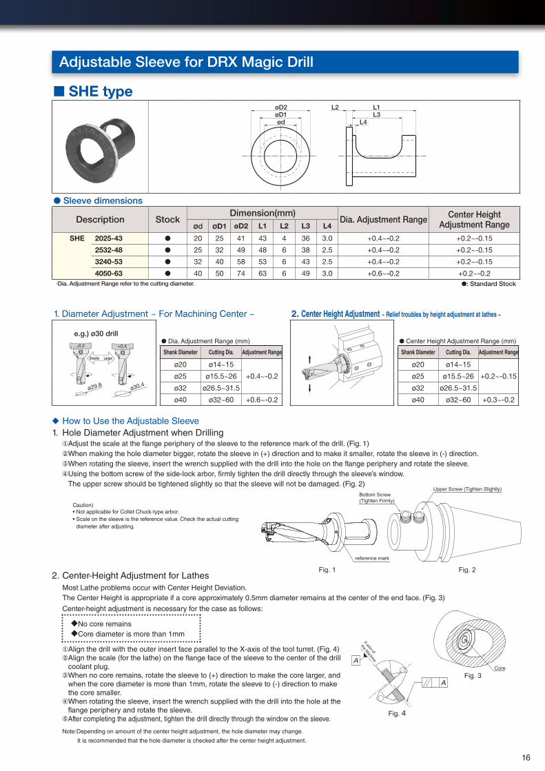
Adjustable Sleeve for DRX Magic Drill
reference mark
Fig. 2Fig. 1
Bottom Screw (Tighten Firmly)
Upper Screw (Tighten Slightly)
CoreFig. 3
Fig. 4
X-axis of
the Machine
A
A
■ SHE type
ød L4L3øD1
øD2 L1L2
● Sleeve dimensions
Description StockDimension(mm)
Dia. Adjustment Range Center Height Adjustment Rangeød øD1 øD2 L1 L2 L3 L4
SHE 2025-43 ● 20 25 41 43 4 36 3.0 +0.4~-0.2 +0.2~-0.15
2532-48 ● 25 32 49 48 6 38 2.5 +0.4~-0.2 +0.2~-0.15
3240-53 ● 32 40 58 53 6 43 2.5 +0.4~-0.2 +0.2~-0.15
4050-63 ● 40 50 74 63 6 49 3.0 +0.6~-0.2 +0.2~-0.2·Dia. Adjustment Range refer to the cutting diameter. ●: Standard Stock
1. Diameter Adjustment ~ For Machining Center ~ 2. Center Height Adjustment ~ Relief troubles by height adjustment at lathes ~
ø29.8
-0.2 +0.4
ø30.4
e.g.) ø30 drill
Smaller Larger
● Dia. Adjustment Range (mm) ● Center Height Adjustment Range (mm)
Shank Diameter Cutting Dia. Adjustment Range Shank Diameter Cutting Dia. Adjustment Range
ø20 ø14~15
+0.4~-0.2
ø20 ø14~15
+0.2~-0.15ø25 ø15.5~26 ø25 ø15.5~26
ø32 ø26.5~31.5 ø32 ø26.5~31.5
ø40 ø32~60 +0.6~-0.2 ø40 ø32~60 +0.3~-0.2
◆ How to Use the Adjustable Sleeve1. Hole Diameter Adjustment when Drilling
①Adjust the scale at the flange periphery of the sleeve to the reference mark of the drill. (Fig. 1)②When making the hole diameter bigger, rotate the sleeve in (+) direction and to make it smaller, rotate the sleeve in (-) direction.③When rotating the sleeve, insert the wrench supplied with the drill into the hole on the flange periphery and rotate the sleeve.④ Using the bottom screw of the side-lock arbor, firmly tighten the drill directly through the sleeve’s window.
The upper screw should be tightened slightly so that the sleeve will not be damaged. (Fig. 2)
Caution) • Not applicable for Collet Chuck-type arbor.• Scale on the sleeve is the reference value. Check the actual cutting
diameter after adjusting.
2. Center-Height Adjustment for LathesMost Lathe problems occur with Center Height Deviation.The Center Height is appropriate if a core approximately 0.5mm diameter remains at the center of the end face. (Fig. 3)
Center-height adjustment is necessary for the case as follows:
◆No core remains◆Core diameter is more than 1mm
①Align the drill with the outer insert face parallel to the X-axis of the tool turret. (Fig. 4)② Align the scale (for the lathe) on the flange face of the sleeve to the center of the drill
coolant plug.③ When no core remains, rotate the sleeve to (+) direction to make the core larger, and
when the core diameter is more than 1mm, rotate the sleeve to (-) direction to make the core smaller.
④ When rotating the sleeve, insert the wrench supplied with the drill into the hole at the flange periphery and rotate the sleeve.
⑤ After completing the adjustment, tighten the drill directly through the window on the sleeve.
Note:Depending on amount of the center height adjustment, the hole diameter may change.
It is recommended that the hole diameter is checked after the center height adjustment.
16
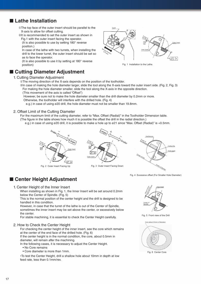
■ Lathe Installation① The top face of the outer insert should be parallel to the
X-axis to allow for offset cutting.② It is recommended to set the outer insert as shown in
Fig.1 with the outer insert facing the operator.(It is also possible to use by setting 180° reverse position.)In case of the lathe with two turrets, when installing the drill to the lower turret, the outer insert should be set so as to face the operator.(It is also possible to use it by setting at 180° reverse position)
Turret
X-axis of the Machine
Inner Insert
Outer Insert
Fig. 1 Installation to the Lathe.
A
A
Moving Directionof X-axis
■ Cutting Diameter Adjustment1. Cutting Diameter Adjustment
①The moving direction of the X-axis depends on the position of the toolholder.② In case of making the hole diameter larger, slide the tool along the X-axis toward the outer insert side. (Fig. 2, Fig. 3)
For making the hole diameter smaller, slide the tool along the X-axis in the opposite direction. (This movement of the axis is called “Offset”)
However, be sure not to make the hole diameter smaller than the drill diameter by 0.2mm or more. Otherwise, the toolholder will interfere with the drilled hole. (Fig. 4)
e.g.) in case of using ø20 drill, the hole diameter must not be smaller than 19.8mm.
2. Offset Limit of the Cutting DiameterFor the maximum limit of the cutting diameter, refer to “Max. Offset (Radial)” in the Toolholder Dimension table.(The figure in the table shows how much it is possible the offset the drill in the radial direction.)
e.g.) in case of using ø20 drill, it is possible to make a hole up to ø21 since “Max. Offset (Radial)” is +0.5mm.
Outer Insert
X-axis ofthe Machine
Smaller
Larger
Fig. 2 Outer Insert Facing Up
X-axis of the Machine
Outer Insert
Larger
Smaller
Fig. 3 Outer Insert Facing Down
Fig. 4 Excessive offset (For Smaller Hole Diameter)
X-axis of the Machine
Outer Insert
Cutting Dia.
Center of Drill
Interference
Center of Spindle
Fig. 5 Front view of the Drill
Inner Insert
Center of Spindle
Abou
t 0.2
mm
be
low
the
Cent
er
Fig. 6 Center Core
Core (about 0.5mm in Diameter)
■ Center Height Adjustment1. Center Height of the Inner Insert
When installing as shown in Fig. 1, the Inner Insert will be set around 0.2mm below the Center of Spindle. (Fig. 5) This is the normal position of the center height and the drill is designed to be handled in this condition.However, in case that the turret of the lathe is out of the Center of Spindle, sometimes the inner insert may be set above the center, or excessively below the center.For stable machining, it is essential to check the Center Height carefully.
2. How to Check the Center HeightFor checking the center height of the inner insert, see the core which remains at the center of the end face of the drilled hole. (Fig. 6)If the center height is in the normal condition, the core, about 0.5mm in diameter, will remain after the machining.In the following cases, it is necessary to adjust the Center Height. • No Core remains • Core diameter is more than 1mm.
*To test the Center Height, drill a shallow hole about 10mm in depth at low feed rate, less than 0.1mm/rev.
17
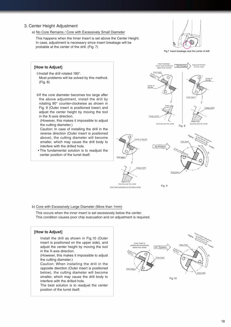
Fig.7 Insert breakage near the center of drill
3. Center Height Adjustmenta) No Core Remains / Core with Excessively Small Diameter
This happens when the Inner Insert is set above the Center Height. In case, adjustment is necessary since insert breakage will be probable at the center of the drill. (Fig. 7)
[How to Adjust]
① Install the drill rotated 180°. Most problems will be solved by this method. (Fig. 8)
② If the core diameter becomes too large after the above adjustment, install the drill by rotating 90° counter-clockwise as shown in Fig. 9 (Outer insert is positioned lower) and adjust the center height by moving the tool in the X-axis direction.
(However, this makes it impossible to adjust the cutting diameter.)
Caution: In case of installing the drill in the reverse direction (Outer insert is positioned above), the cutting diameter will become smaller, which may cause the drill body to interfere with the drilled hole.
• The fundamental solution is to readjust the center position of the turret itself.
Initial Installation (Inner insert positioned
higher than normal)
Improved Positionof Inner Insert180°Rotation
Inner Insert
Inner Insert
Center of Spindle
X-axis of theMachine
Center of Spindle
Zooming near the center Zooming near the center
Center of Drill
Center of Drill
InnerInsert
InnerInsert
Fig. 8
90°Rotation
Inner Insert
Inner Insert
Outer Insert
Center of Spindle
X-axis of the Machine
Center Height Adjustment
by Moving the Tool
Higher
Lower
90°
Center of Drill
InnerInsert
Fig. 9Zooming near the center
Inner Insert positioned too far below center
b) Core with Excessively Large Diameter (More than 1mm)
This occurs when the inner insert is set excessively below the center.This condition causes poor chip evacuation and on adjustment is required.
[How to Adjust]
Install the drill as shown in Fig.10 (Outer insert is positioned on the upper side), and adjust the center height by moving the tool in the X-axis direction.(However, this makes it impossible to adjust the cutting diameter.) Caution: When installing the drill in the opposite dierction (Outer insert is positioned below), the cutting diameter will become smaller, which may cause the drill body to interfere with the drilled hole.The best solution is to readjust the center position of the turret itself.
Center Height Adjustment
by Moving the Tool
Higher
Lower
Inner Insert
Inner Insert
Outer Insert
Outer Insert
X-axis of the Machine
X-axis of the Machine
90° Rotation
Fig.10
Inner insert is positioned excessively
below the center.
90°
18
6pcs/edge
Less material welding, continue to use even after 400 holes
1300pcs/edge
Cycle time : 28minutes/pc
Breakage after 4 holes
Large material welding (after 400 holes)
500pcs/edge
Cycle time : 58minutes/pc
50% reduction
Cutting edge of DRX (after 400 holes)
Cutting edge of competitors (after 400 holes)
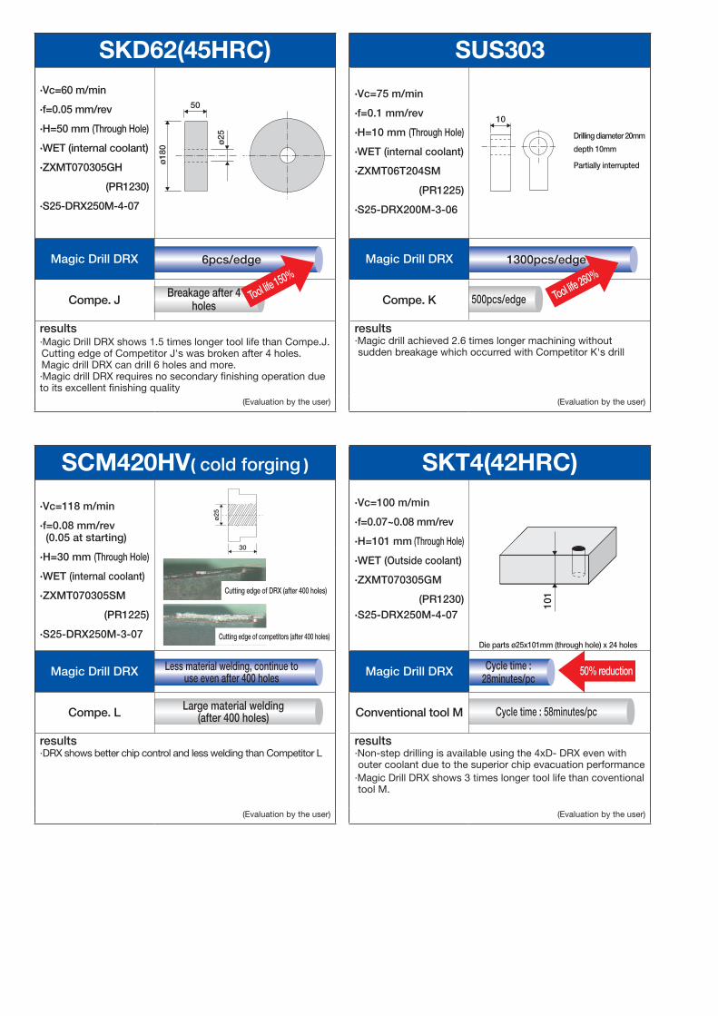
SUS303
·Vc=75 m/min
·f=0.1 mm/rev
·H=10 mm (Through Hole)
·WET (internal coolant)
·ZXMT06T204SM
(PR1225)
·S25-DRX200M-3-06
10
Drilling diameter 20mm
depth 10mm
Partially interrupted
Magic Drill DRX
Compe. K
results ·Magic drill achieved 2.6 times longer machining without sudden breakage which occurred with Competitor K's drill
(Evaluation by the user)
SKD62(45HRC)·Vc=60 m/min
·f=0.05 mm/rev
·H=50 mm (Through Hole)
·WET (internal coolant)
·ZXMT070305GH
(PR1230)
·S25-DRX250M-4-07ø
25
ø18
0
50
Magic Drill DRX
Compe. J
results·Magic Drill DRX shows 1.5 times longer tool life than Compe.J.Cutting edge of Competitor J's was broken after 4 holes.Magic drill DRX can drill 6 holes and more.·Magic drill DRX requires no secondary finishing operation due to its excellent finishing quality
(Evaluation by the user)
SCM420HV( cold forging )
·Vc=118 m/min
·f=0.08 mm/rev (0.05 at starting)
·H=30 mm (Through Hole)
·WET (internal coolant)
·ZXMT070305SM
(PR1225)
·S25-DRX250M-3-07
ø25
30
Magic Drill DRX
Compe. L
results·DRX shows better chip control and less welding than Competitor L
(Evaluation by the user)
Tool life 150%
Tool life 260%
SKT4(42HRC)·Vc=100 m/min
·f=0.07~0.08 mm/rev
·H=101 mm (Through Hole)
·WET (Outside coolant)
·ZXMT070305GM
(PR1230)·S25-DRX250M-4-07
101
Die parts ø25x101mm (through hole) x 24 holes
Magic Drill DRX
Conventional tool M
results·Non-step drilling is available using the 4xD- DRX even with outer coolant due to the superior chip evacuation performance
·Magic Drill DRX shows 3 times longer tool life than coventional tool M.
(Evaluation by the user)