Embed Size (px)
Citation preview

Geosci. Instrum. Method. Data Syst., 2, 329–337, 2013www.geosci-instrum-method-data-syst.net/2/329/2013/doi:10.5194/gi-2-329-2013© Author(s) 2013. CC Attribution 3.0 License.
GeoscientificInstrumentation
Methods andData Systems
Open A
ccess
Drilling cores on the sea floor with the remote-controlled sea floordrilling rig MeBo
T. Freudenthal and G. Wefer
MARUM Center for Marine Environmental Sciences, University of Bremen, Bremen, Germany
Correspondence to:T. Freudenthal ([email protected])
Received: 11 June 2013 – Published in Geosci. Instrum. Method. Data Syst. Discuss.: 1 July 2013Revised: 9 December 2013 – Accepted: 9 December 2013 – Published: 20 December 2013
Abstract. The sea floor drill rig MeBo (acronym forMeeresboden-Bohrgerät, German for sea floor drill rig) is arobotic drill rig that is deployed on the sea floor and oper-ated remotely from the research vessel to drill up to 80 minto the sea floor. It was developed at the MARUM Re-search Center for Marine Environmental Sciences at BremenUniversity. The complete system – comprising the drill rig,winch, control station, and the launch and recovery system –is transported in six containers and can be deployed world-wide from German and international research ships. It wasthe first remote-controlled deep sea drill rig to use a wirelinecoring technique. Compared to drilling vessels this technol-ogy has the advantage of operating from a stable platform atthe sea bed, which allows for optimal control over the drillingprocess. Especially for shallow drillings in the range of tensto hundreds of metres, sea bed drill rigs are time-efficientsince no drill string has to be assembled from the ship to thesea floor before the first core can be taken. The MeBo hasbeen successfully operated, retrieving high-quality cores atthe sea bed for a variety of research fields, including slopestability studies and palaeoclimate reconstructions. Based onexperience with the MeBo, a rig is now being built that willbe able to drill to a depth of 200 m.
1 Introduction
Conventional methods of sampling the sea floor from re-search ships include the use of vibracores, gravity coresand piston cores. With these robust and reliable instruments,cores with lengths of 5–15 m (up to 50 m in rare cases) canbe retrieved in areas of unconsolidated sediments on the sea
floor (Hebbeln, 2003). Dredging is used to collect blocks ofhard rock lying on the sea floor.
Drilling ships are usually employed when longer sedimentcores are necessary or if cores from hard-rock provinces aretargeted (Hebbeln, 2003). These ships can drill cores downto several hundred metres, or even kilometres deep. How-ever, the use of drilling ships is expensive and not efficientfor shallow drilling needs (McGinnis, 2009). Before the ac-tual drilling process can begin, a drill string has to be assem-bled that extends from the ship to the sea floor. Vibrationsin the drill string and movements of the ship prevent opti-mal control of the drill-head pressure, which considerablycompromises the core quality, especially in the upper tens ofmetres.
There are increasing needs both in research and indus-try for shallow drilling (Sager et al., 2003; Yetginer andTjelta, 2011). The construction of foundations and anchorsfor offshore installations is very dependent on the geotechni-cal properties of the sea floor. Exploration for mineral de-posits such as sulfide mineralization around hydrothermalsystems or investigations of methane hydrate deposits alsorequire the drilling of numerous shallow holes (Ishibashi etal., 2007; Spencer et al., 2011). Palaeoclimate studies are en-hanced by the ability to obtain cores that are longer thanthose from conventional methods because the marine sedi-ments are an archive for the reconstruction of past environ-mental conditions. Studies of three-dimensional structures onthe sea floor, such as mud volcanoes and slope slumps, re-quire a large number of shallow holes that cannot be effec-tively cored either by the conventional methods on currentmulti-purpose research vessels or by drill ships.
Published by Copernicus Publications on behalf of the European Geosciences Union.

330 T. Freudenthal and G. Wefer: Drilling cores on the sea floor
Fig. 1. Typical operational setup for a remote-controlled drill rigthat is lowered to the sea floor. As an example, the sea floor drill rigMeBo and the research vesselMaria S. Merianis shown.
2 Examples and advantages of robotic drilling systems
Robotic drilling rigs that are lowered onto the sea floor frommulti-purpose research vessels and that retrieve cores fromthe sub-bottom by remote control from the ship (Fig. 1) canhelp to fill the gap between relatively inexpensive conven-tional methods – like vibracoring, gravity coring or pistoncoring – and the use of drill ships. For deployment on the seafloor, several drill rigs have been developed that use a singlecore barrel and can drill to a depth of up to 5 m, as well asother rigs that have a drill-pipe magazine (multi-barrel). Forthe latter, extension pipes can be attached to the drill stringand thus significantly greater coring depths can be achieved.
To our knowledge, the first example of a remotely oper-ated sea floor drill rig was the MARICOR, developed in 1973by Atlas Copco. This rig was configured for deployment oncontinental shelves down to 200 m water depth and a drillingdepth of 60 m using a diamond rotary drilling method.
The British Geological Survey (BGS) operates two single-barrel drill rigs (Wilson, 2006). The 5 m rock drill (RD1)was developed in 1982. A smaller 1 m drill can retrieve anoriented core for palaeomagnetic studies (MacLeod et al.,2002). In 2006 the BGS developed a multi-barrel rig thatcould drill to a depth of 15 m (Wilson, 2006) and has nowbeen upgraded for a drilling depth of 50 m.
In 1989/1990 the American company Williamson and As-sociates built a 3 m drill rig (Johnson, 1991), and in 1996,2005 and 2008 they produced the Benthic Multicoring Sys-tems BMS-1, BMS-2 and BMS 3, respectively. The BMSdrills are operated on the research shipHakurei No. 2bythe Metal Mining Agency of Japan and can drill to a depthof 20 m (Ishibashi et al., 2007) in unconsolidated sedimentsor in hard rocks. In 2008 Williamson and Associates devel-oped a sea bed drill rig called an Autonomous Coring System
(ACS) for the National Institute of Ocean Technology in In-dia designed for recovering up to 100 m-long cores at 3000 mwater depth.
The Australian company Benthic Geotech Pty Ltd hasbeen operating the Portable Remotely Operated Drill(PROD) since 1997, a multi-barrel drill rig that can retrievecores up to 100 m long in unconsolidated sediments or hardrocks (Stuart, 2004; Pallanich, 2010).
In 2011 the Californian company Gregg Drilling togetherwith several companies, including Marl Technologies andSchilling Robotics, developed the Gregg sea floor drill forup to 150 m deep drilling for geotechnical purposes.
All of the described drill rigs are controlled and suppliedwith energy from the ship through a special steel-armouredcable. These drilling tools present new possibilities for sam-pling from conventional research ships. The multi-barrel rigsare especially well suited for filling the growing need by bothmarine research and offshore industry for cores of 30–100 mlength on the continental shelf areas as well as in the deepsea. These remote-controlled drills have significant advan-tages over drill ships.
– Ship and drill-string motion due to wind, currents andwaves do not affect the quality of the drilling processbecause the work is done from a stable platform on thesea floor.
– Robotic drill rigs can be launched from various avail-able multi-purpose research ships. This can reduce themobilization costs for worldwide deployment.
– As a rule, drilling ships are expensive and heavilybooked. By avoiding the time-consuming assembly ofa drill string from the drilling ship to the sea floor, theuse of drill rigs placed on the sea floor can be substan-tially more time- and cost-effective.
A similar concept to the remote-controlled drilling on the seafloor is implemented by drills mounted on submarine robots(remotely operated vehicle, ROV). The ROV is connected tothe vessel by an umbilical and is used for navigation, datatransfer, and supply of hydraulic energy for the drill rig. TheMBARI ROV-mounted rig can drill horizontal cores with amaximum length of 1 m (Stakes et al., 1997). The Rovdrill®,which was developed by Perry Slingsby, drills vertically andcan attain depths of up to 20 m. The third generation of thisdevelopment, called Rovdrill 3, is designed for a maximumcoring depth of more than 80 m (Spencer et al., 2011).
3 The sea floor drill rig MeBo
From 2004 to 2005, the sea floor drill rig MeBo (Fig. 2;Table 1) was developed at the MARUM Center for MarineEnvironmental Sciences at Bremen University with fundingfrom the Federal Government of Germany (Education andResearch) and the State of Bremen (Freudenthal and Wefer,
Geosci. Instrum. Method. Data Syst., 2, 329–337, 2013 www.geosci-instrum-method-data-syst.net/2/329/2013/
T. Freudenthal and G. Wefer: Drilling cores on the sea floor 331
Fig. 2.The sea floor drill rig MeBo during the deployment start fromthe research vessel RVPourquoi Pas?in November 2011 (photo: T.Klein, Marum).
2007). MeBo is the acronym forMeeresboden-Bohrgerät,German for sea floor drill rig. This is the first drill rig de-veloped and operated by a scientific institute that can drillcores up to 80 m deep in unconsolidated sediments and inhard rocks. It is the first robotic deep sea drilling rig in theworld that can drill cores using both conventional and theadvanced wireline methods.
As far as is possible, the MeBo uses proven technologythat has been time-tested in onshore drilling systems or oncommercial ROVs. Special requirements for its constructionincluded the following:
– convenience of transportation on land and sea,
– 10 t maximum weight,
– drilling capability in both unconsolidated sedimentsand hard rocks,
– drilling depth of at least 50 m,
– core diameter of 50–80 mm,
– deployment depth up to 2000 m (with the option to4000 m)
It was developed in close cooperation with the companiesPrakla Bohrtechnik GmbH and Schilling Robotics. The Ger-man company Prakla Bohrtechnik GmbH in Peine was pri-marily responsible for the mechanical and hydraulic devel-opment. The California-based company Schilling Roboticsdeveloped the core-barrel magazine with the loading armand also provided the telemetry system for data transfer andoperating energy. MARUM was responsible for the systemdesign, energy supply and deployment concept and also de-veloped the control system (hardware and software) for theMeBo. 20
1
2
Figure 3. View toward the stern on the working deck of the research vessel Meteor during 3
deployment of the MeBo. In front are the workshop and control containers, behind them the 4
drill pipe storage and winch, and behind those the launch and recovery system for the MeBo 5
(Photo: V. Diekamp, Marum). 6
7
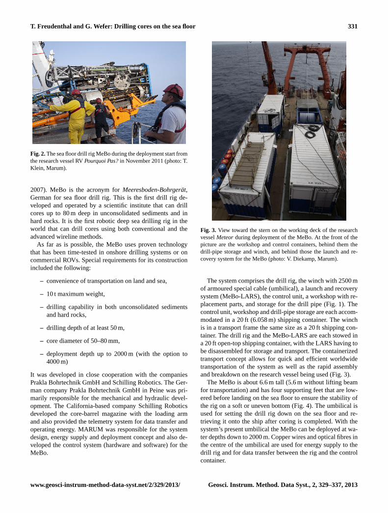
Fig. 3. View toward the stern on the working deck of the researchvesselMeteorduring deployment of the MeBo. At the front of thepicture are the workshop and control containers, behind them thedrill-pipe storage and winch, and behind those the launch and re-covery system for the MeBo (photo: V. Diekamp, Marum).
The system comprises the drill rig, the winch with 2500 mof armoured special cable (umbilical), a launch and recoverysystem (MeBo-LARS), the control unit, a workshop with re-placement parts, and storage for the drill pipe (Fig. 1). Thecontrol unit, workshop and drill-pipe storage are each accom-modated in a 20 ft (6.058 m) shipping container. The winchis in a transport frame the same size as a 20 ft shipping con-tainer. The drill rig and the MeBo-LARS are each stowed ina 20 ft open-top shipping container, with the LARS having tobe disassembled for storage and transport. The containerizedtransport concept allows for quick and efficient worldwidetransportation of the system as well as the rapid assemblyand breakdown on the research vessel being used (Fig. 3).
The MeBo is about 6.6 m tall (5.6 m without lifting beamfor transportation) and has four supporting feet that are low-ered before landing on the sea floor to ensure the stability ofthe rig on a soft or uneven bottom (Fig. 4). The umbilical isused for setting the drill rig down on the sea floor and re-trieving it onto the ship after coring is completed. With thesystem’s present umbilical the MeBo can be deployed at wa-ter depths down to 2000 m. Copper wires and optical fibres inthe centre of the umbilical are used for energy supply to thedrill rig and for data transfer between the rig and the controlcontainer.
www.geosci-instrum-method-data-syst.net/2/329/2013/ Geosci. Instrum. Method. Data Syst., 2, 329–337, 2013
332 T. Freudenthal and G. Wefer: Drilling cores on the sea floor
21
1
2
Figure 4. Schematic overview of the major components of the MeBo. 3
4
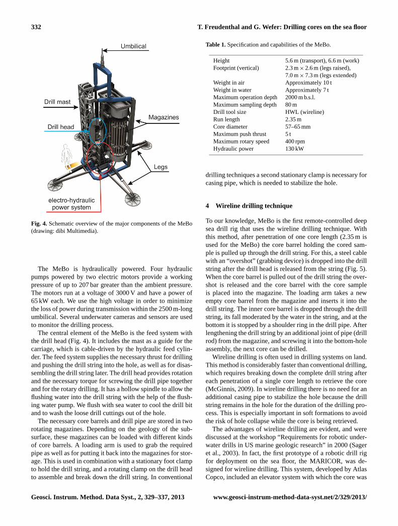
Fig. 4. Schematic overview of the major components of the MeBo(drawing: dibi Multimedia).
The MeBo is hydraulically powered. Four hydraulicpumps powered by two electric motors provide a workingpressure of up to 207 bar greater than the ambient pressure.The motors run at a voltage of 3000 V and have a power of65 kW each. We use the high voltage in order to minimizethe loss of power during transmission within the 2500 m-longumbilical. Several underwater cameras and sensors are usedto monitor the drilling process.
The central element of the MeBo is the feed system withthe drill head (Fig. 4). It includes the mast as a guide for thecarriage, which is cable-driven by the hydraulic feed cylin-der. The feed system supplies the necessary thrust for drillingand pushing the drill string into the hole, as well as for disas-sembling the drill string later. The drill head provides rotationand the necessary torque for screwing the drill pipe togetherand for the rotary drilling. It has a hollow spindle to allow theflushing water into the drill string with the help of the flush-ing water pump. We flush with sea water to cool the drill bitand to wash the loose drill cuttings out of the hole.
The necessary core barrels and drill pipe are stored in tworotating magazines. Depending on the geology of the sub-surface, these magazines can be loaded with different kindsof core barrels. A loading arm is used to grab the requiredpipe as well as for putting it back into the magazines for stor-age. This is used in combination with a stationary foot clampto hold the drill string, and a rotating clamp on the drill headto assemble and break down the drill string. In conventional
Table 1.Specification and capabilities of the MeBo.
Height 5.6 m (transport), 6.6 m (work)Footprint (vertical) 2.3 m× 2.6 m (legs raised),
7.0 m× 7.3 m (legs extended)Weight in air Approximately 10 tWeight in water Approximately 7 tMaximum operation depth 2000 m b.s.l.Maximum sampling depth 80 mDrill tool size HWL (wireline)Run length 2.35 mCore diameter 57–65 mmMaximum push thrust 5 tMaximum rotary speed 400 rpmHydraulic power 130 kW
drilling techniques a second stationary clamp is necessary forcasing pipe, which is needed to stabilize the hole.
4 Wireline drilling technique
To our knowledge, MeBo is the first remote-controlled deepsea drill rig that uses the wireline drilling technique. Withthis method, after penetration of one core length (2.35 m isused for the MeBo) the core barrel holding the cored sam-ple is pulled up through the drill string. For this, a steel cablewith an “overshot” (grabbing device) is dropped into the drillstring after the drill head is released from the string (Fig. 5).When the core barrel is pulled out of the drill string the over-shot is released and the core barrel with the core sampleis placed into the magazine. The loading arm takes a newempty core barrel from the magazine and inserts it into thedrill string. The inner core barrel is dropped through the drillstring, its fall moderated by the water in the string, and at thebottom it is stopped by a shoulder ring in the drill pipe. Afterlengthening the drill string by an additional joint of pipe (drillrod) from the magazine, and screwing it into the bottom-holeassembly, the next core can be drilled.
Wireline drilling is often used in drilling systems on land.This method is considerably faster than conventional drilling,which requires breaking down the complete drill string aftereach penetration of a single core length to retrieve the core(McGinnis, 2009). In wireline drilling there is no need for anadditional casing pipe to stabilize the hole because the drillstring remains in the hole for the duration of the drilling pro-cess. This is especially important in soft formations to avoidthe risk of hole collapse while the core is being retrieved.
The advantages of wireline drilling are evident, and werediscussed at the workshop “Requirements for robotic under-water drills in US marine geologic research” in 2000 (Sageret al., 2003). In fact, the first prototype of a robotic drill rigfor deployment on the sea floor, the MARICOR, was de-signed for wireline drilling. This system, developed by AtlasCopco, included an elevator system with which the core was
Geosci. Instrum. Method. Data Syst., 2, 329–337, 2013 www.geosci-instrum-method-data-syst.net/2/329/2013/

T. Freudenthal and G. Wefer: Drilling cores on the sea floor 333
22
1
2
Figure 5. View of the lower fixed foot clamp of the MeBo. The “overshot” is lowered into the 3
drill string on a steel cable (Photo: Marum). 4
5
Fig. 5.View of the lower fixed foot clamp of the MeBo. The “over-shot” is lowered into the drill string on a steel cable (photo: Marum).
pulled up to the deck of the research vessel immediately af-ter it was drilled. The MARICOR project, however, was can-celled after its first trials (A. Oden, personal communication,2003). All subsequent remote-controlled drill rigs that weredeveloped up to 2007 for use on the sea floor (BMS, PROD,Rovdrill) use the conventional drilling procedure. Becausewireline drilling involves a much higher complexity of oper-ational steps, we at MARUM also initially decided to config-ure the MeBo for conventional coring. After four successfulresearch expeditions with the MeBo through 2007 (Freuden-thal and Wefer, 2007), we undertook the further developmen-tal decision to upgrade the MeBo for use with the wirelinetechnique.
In contrast to land-based drilling systems, remote-controlled operation of wireline drilling cannot be manuallysupported. During the upgrade of the MeBo for use withwireline drilling, special attention was therefore given to theprocesses that are normally supported by the drill foremanon the rig. These include guiding the overshot into the drillstring with an additional manipulator, checking the landingof the inner core barrel on the shoulder ring, secure wind-ing of the winch for the cable, releasing the overshot fromthe core barrel after retrieval from the drill string (Freuden-thal et al., 2012) and preparation of the overshot for the nextapplication.
Due to the space saved in magazine storage for the addi-tional pipe needed for conventional drilling, the maximumdrilling depth is increased from 50 m to over 80 m with thewireline method (Table 2). The advantages of the wirelinemethod have been demonstrated on 10 expeditions with theMeBo since 2008. Average core recovery rates were close to80 % in different types of geologies including hemipelagicmuds, gas-hydrate-bearing sediments, sands, glacial till andcarbonate rock. Since wireline coring tools were initially de-veloped for hard rock drilling, we developed special adap-
Table 2.Comparison of drill-pipe sizes used by the MeBo for con-ventional and wireline drilling.
Conventional Wireline
Pipe size T2-101 HWLDrilling diameter 103 mm 103 mmCore diameterHard rock 84 mm 65 mmSediment 80 mm 57 mmCore length 3000 mm 2350 mmMaximum drilling depth ∼ 50 m ∼ 80 m
tions for improving the core recovery for soft sediments. Ex-amples of cores collected in different types of sediments areshown in Fig. 6.
5 Auxiliary equipment
An autonomous probe for obtaining bore-hole measurementshas also been developed for use with the MeBo. In a proce-dure called logging while tripping, the probe, equipped withits own energy source and data storage, is lowered into thedrill string after the last core barrel has been retrieved. Afterthe probe has landed on the shoulder ring at the bottom ofthe hole, the drill string is pulled out and disassembled. Theprobe, while being raised with the drill string, continuouslymeasures the geophysical properties of the borehole and thein situ sediments and rocks. Major advantages of the logging-while-tripping method are a minimum time requirement forthe borehole logging since the drill string has to be trippedout anyway as well as the capability of logging unstable for-mations since the drill string stabilizes the drilled hole duringthe logging.
Figure 7 shows the results of core drilling and boreholelogging at station GeoB 16602 drilled during the RVSonneexpedition SO221 in May 2012 in the South China Sea. Onegravity core and three MeBo deployments were conductedwithin about 100 m distance at the continental slope of theSouth China Sea in 950 m water depth. A drilling depth ofmore than 80 m was reached by flushing through the upper10 m (reach of the gravity corer) and by core-drilling below.The parallel holes were drilled in order to get more samplematerial and close gaps in the drilling profile. By splicingthe records a continuous profile is obtained for palaeocli-mate reconstructions in this area sensitive to changes in theSouth East Asian monsoon system. During two of the MeBodeployments, bore-hole measurements were conducted witha spectrum gamma ray probe in the logging-while-trippingmode. This probe measures the natural gamma ray signaland analyses the spectrum with respect to the concentrationsof the three natural gamma-ray-emitting elements potas-sium, uranium and thorium. The total gamma ray counts arecalibrated by an artificial radioactive formation. Formation
www.geosci-instrum-method-data-syst.net/2/329/2013/ Geosci. Instrum. Method. Data Syst., 2, 329–337, 2013

334 T. Freudenthal and G. Wefer: Drilling cores on the sea floor
23
1
2
Figure 6. High quality cores were drilled with MeBo from massive gas hydrate layers (a), and 3
hemipelagic muds containing authigenic carbonate precipitates (b) and ash layers (c). Arrows 4
point to sharp contact at the base of the ash layer and bioturbation structures at the top which 5
are indicators of minimum disturbance of the sediments during drilling. (Photos: Marum). 6
7
Fig. 6. High-quality cores drilled with the MeBo from massive gashydrate layers(a), and hemipelagic muds containing authigenic car-bonate precipitates(b) and ash layers(c). Arrows point to sharpcontact at the base of the ash layer and bioturbation structures at thetop, which are indicators of minimum disturbance of the sedimentsduring drilling. (photos: Marum).
gamma ray signal is expressed in the internationally acceptedgAPI unit (Ellis and Singer, 2007). A close correlation of thelogging profiles is observed between the independently ac-quired profiles at this site. Natural gamma ray signal (NGR)ranges from 44 to 90 gAPI. The variations in NGR are mainlyattributed to changes in concentrations of potassium (0.5–1.6 %) and thorium (4.1–13.0 ppm), whereas uranium con-centrations are fairly low (1.2–3.1 ppm).
Clays are the main host minerals for thorium and potas-sium in marine sediments. The variability in NGR can there-fore be interpreted as an indicator of changes in terrestrialsediment input into the South China Sea at the two sites.Since the monsoon system is a key factor controlling weath-ering and terrigenous material transport by rivers, the bore-hole logging results will help in reconstructing past climatechanges in that area.
24
1
2
Figure 7. Core recovery with a gravity core (GeoB16602-4) and three separate MeBo 3
deployments (GeoB16602-5, GeoB16602-7, GeoB16602-8) and bore hole logging results of 4
MeBo deployments GeoB16602-5 and GeoB16602-7 at the continental slope of the South 5
China Sea in 950 m water depth. 6
7
Fig. 7. Core recovery with a gravity core (GeoB16602-4) andthree separate MeBo deployments (GeoB16602-5, GeoB16602-7,GeoB16602-8) and borehole logging results of MeBo deploymentsGeoB16602-5 and GeoB16602-7 at the continental slope of theSouth China Sea at 950 m water depth.
Borehole instrumentation and the hydraulic sealing of theborehole against the overlying ocean body with a CORK(circulation obviation retrofit kit) is required for long-termmonitoring of borehole pressure changes related, for ex-ample, to earthquakes and fluid migration within the sedi-ments (Becker and Davies, 2005; Kopf et al., 2011). An au-tonomous MeBo-CORK instrument was developed that canbe deployed with the MeBo after core drilling is completed(Kopf et al., 2013). It was installed in a custom-built MeBodrill string termination and deployed for the first time inJune 2012 during an expedition of the research vesselSonne(Fig. 8). It contained pressure and temperature transducers inthe borehole as well as outside the borehole for sea floor ref-erence. This instrument also includes a data logger, a batteryunit and an acoustic modem for data transfer. Unlike otherCORK systems the MeBo approach does not require instal-lation assistance by ROVs (Becker and Davies, 2005) and istherefore versatile to install.
6 MeBo operations
Since its development in 2004/2005 the MeBo was deployedduring 14 expeditions on 5 different multi-purpose researchvessels. These vessels include the 65.5 m-long Irish vesselRV Celtic Explorer, the 94.8 to 97.6 m-long German researchvessels RVMaria S. Merian, RV Meteor and RV Sonne,and the 107.6 m-long French vessel RVPourquoi Pas?(Ta-ble 3). A research vessel suitable for the deployment of theMeBo needs an A-frame strong enough for lifting the drillrig (weight in water is 7 t plus 1–2 t magazine loading plus 3 tper kilometre of umbilical weight) at dynamic conditions. Acareful catenary management in order to prevent twisting ofthe umbilical depends on good navigation capabilities of theresearch vessel, preferably using dynamic positioning (DP).
Geosci. Instrum. Method. Data Syst., 2, 329–337, 2013 www.geosci-instrum-method-data-syst.net/2/329/2013/

T. Freudenthal and G. Wefer: Drilling cores on the sea floor 335
Table 3.Vessels used so far for the operation of the MeBo.
Research Length Gross A-Frame SWL ExpeditionsVessel [m] tonnage [kN] [Name (year), chief scientist, area]
Celtic Explorer 65.5 2425 250 CE0511 (2005), Freudenthal, Baltic SeaCE0619 (2006), Murray, off IrelandCE0810 (2008), Wheeler, off Ireland
Maria S. Merian 94.8 5573 200 MSM04/4 (2007), Freudenthal, off MoroccoMSM15/3 (2010), Huhn, off SicilyMSM30 (2013), Hanebuth, W. Barents Sea
Meteor 97.5 4280 200 M65/3 (2005), Wefer, off MoroccoM76/1 (2008), Zabel, off NamibiaM78/3 (2009), Wefer, off ArgentineM84/2 (2011), Bohrmann, Black Sea
Sonne 97.6 3557 100 SO211 (2010), Hebbeln, off ChileSO221 (2012), Mohtadi, South China SeaSO222 (2012), Kopf, off Japan
Pourquoi Pas? 107.6 7854 220 GUINECOMeBo (2011), Sultan, off Nigeria
25
1
2
Figure 8. Picture of a MeBo-CORK installed in June 2012 with MeBo. The picture was taken 3
a few days after installation with a towed camera sled, the Ocean Floor Observation System 4
(OFOS) of the research vessel SONNE. Note the imprint of the base frame and of the legs of 5
the MeBo on the sea floor. The distance weight on a 2 m rope at the lower right of the picture 6
belongs to the camera sled and assists the winch driver in assessing distance to sea floor 7
(Photo: Marum). 8
Fig. 8. Picture of a MeBo-CORK installed in June 2012 with theMeBo. The picture was taken a few days after installation with atowed camera sled, the Ocean Floor Observation System (OFOS)of the research vesselSonne. Note the imprint of the base frame andof the legs of the MeBo on the sea floor. The distance weight ona 2 m rope in the lower right of the picture belongs to the camerasled and assists the winch driver in assessing distance to sea floor(photo: Marum).
A length of free deck space of approximately 16–20 m isrequired in front of the A-frame for installation of the launchand recovery system of the MeBo and the 30 t lift umbilicalwinch. Additional deck space is needed for storing the work-shop container, the drill tool container and the control con-tainer. The workshop container hosts spare parts and toolsfor maintenance and repair of the system. Core barrels androds, as well as drill bits and core catchers, for different typesof geology are stored in the drill tool container. The opera-tor console includes a video wall for displaying the images
of eight sub-sea cameras mounted on the drill rig as wellas three deck cameras and belongs to the fixed installationswithin the control container. Together with the launch and re-covery system, the winch, the drill rig and the containers, thepayload of the MeBo system sums up to approximately 90 t.
The MeBo is operated by a total of ten technicians. Threeshifts of two operators each alternate in running the drill rig24 h per day. Four technicians assist the launch and recov-ery, prepare the drill tools, change the loading of the mag-azines and conduct the maintenance and repair (if required)when the MeBo is on deck. The turnover time between twodeployments typically takes 12 h, while a drilling operationdown to 80 m below sea floor in soft sediments requires 30to 36 h operation time.
Approximately 2000 m of drilling has been done so farduring 101 deployments (conventional and wireline drilling)at water depths between 10 and 2050 m. The average corerecovery was 73 % in different types of geologies includ-ing sedimentary and crystalline rocks, glacial tills, sands andhemiplegic muds. Recovery rates of more than 90 % wereachieved especially in hard rock formations and cohesivesediments, while sands and gravels are difficult to samplewith the wireline rotary drilling method.
Especially when shallow drillings of less than 100 m be-low sea floor are required, the MeBo provides a cost- andtime-effective alternative to the use of drilling vessels. Evenin difficult geologies like fractured rock or alternating lay-ers of indurated and unconsolidated sediments, the MeBoshowed good drilling results since drilling from a stable plat-form on the sea bed provides optimal control over the drillingparameters, especially over weight on the bit. High-qualitycores drilled with the MeBo provided ground truth for the in-terpretation of seismic profiles (Krastel et al., 2011). MeBocores drilled off Sicily were used for geotechnical testing ofsediments for slope stability research (Ai et al., 2013). Long,
www.geosci-instrum-method-data-syst.net/2/329/2013/ Geosci. Instrum. Method. Data Syst., 2, 329–337, 2013

336 T. Freudenthal and G. Wefer: Drilling cores on the sea floor
continuous records for palaeoceanographic research can beacquired by double-hole drilling with MeBo and subsequentsplicing of the records. Using this method a 970 000 yr recordof past changes in intermediate water mass characteristics inthe SE Pacific was analysed based on cores drilled with theMeBo off Chile (Martínez-Méndez et al., 2013).
So far the MeBo has been operated in the Atlantic andPacific Ocean in low and high latitudes as well as in the BlackSea, Mediterranean Sea and Baltic Sea. The MeBo system isoperated worldwide with reasonable logistical effort since itis operated on vessels of opportunity.
7 MeBo200
Based on the experience of the successful MeBo develop-ment and deployments, we are presently developing, withfunding from the Federal Government of Germany (Min-istery of Education and Research, BMBF), the second-generation MeBo: MeBo200. This drill rig will be able toconduct core drilling down to 200 m below sea floor. Its de-velopment is within a cooperation of the company BAUERMaschinen GmbH – responsible for the drill mechanics andhydraulics – and MARUM. By optimizing the interplay be-tween loading arm, chucks and the feeding system, we wereable to increase the stroke length from 2.35 to 3.5 m. TheMeBo200 is mounted in a 20 ft transport frame, allowing forstandard container shipping. As a result of this it was pos-sible also to increase the loading capacity of the magazines,which together with the increased stroke length results in asubstantial increase of the drilling depth capabilities.
8 Summary and conclusions
The sea floor drill rig MeBo is a robotic drill rig that is de-ployed on the sea bed and remotely controlled from the re-search vessel. H-size drill tools for wireline core drilling arestored in two magazines on the drill rig and allow for drillingdown to 80 m below sea floor for coring soft sediments aswell as hard rocks. A 2500 m-long umbilical is used for lift-ing the 10 t device as well as for energy supply and datatransfer. The MeBo system comprises the drill rig, the liftumbilical winch, the control station and the launch and re-covery system, and is transported in six containers. It is de-ployed worldwide from German and international researchships and proved its capability during 14 scientific expedi-tions between 2005 and 2012. Average core recovery ratesof 73 % were achieved in different types of geologies in-cluding hemipelagic muds, gas-hydrate-bearing sediments,sands, glacial till and carbonate rock. Besides core drilling,the MeBo is used for borehole logging in the logging-while-tripping mode as well as for the instrumentation of bore-holes for long-term monitoring of pressure and temperaturechanges within the sediments. Experience with the MeBo isnow being used for developing a second-generation drill rig
called MeBo200, which is capable of drilling down to a depthof 200 m below sea floor.
Acknowledgements.The authors thank the MARUM personnelfor their valuable contributions to the development and operationof the MeBo. Development of the MeBo was supported by theBundesministerium für Bildung und Forschung (Federal Min-istry of Education and Research) and by the State of Bremen.Operational support was provided by funding from the DFG(DFG-Forschungszentrum/Excellenzcluster “The Ocean in theEarth System”), by the Senatskommission für Ozeanographie(Senate Commission for Oceanography) and by the coordinationheadquarters for theMeteor/Merian. We also thank the captainsand crews of the research shipsMeteor, Maria S. Merian, Sonne,Pourquoi Pas?and Celtic Explorer for their support during theresearch expeditions with the MeBo.
Edited by: A.-M. Harri
References
Ai, F., Kuhlmann, J., Huhn, K., Strasser, M., and Kopf, A.: Subma-rine slope stability assessment of the central Mediterranean con-tinental margin: the Gela Basin, in: Submarine Mass Movementsand Their Consequences, edited by: Krastel, S., Behrmann, J.-H.,Völker, D., Stipp, M., Berndt, C., Urgeles, R., Chaytor, J., Huhn,K., Strasser, M., and Harbitz, C. B., Springer, 225–238, 2013.
Becker, K. and Davis, E. E.: A review of CORK designs and op-erations during the Ocean Drilling Program, Proc. IODP, 301,doi:10.2204/iodp.proc.301.104.2005, 2005.
Ellis, D. V. and Singer, J. M.: Well logging for earth scientists, 2ndEdn., Springer, Dordrecht, 692 pp., 2007.
Freudenthal, T. and Wefer, G.: Scientific drilling with the sea floordrill rig MeBo, Ocean Drilling, 5, 63–66, 2007.
Freudenthal, T., Mühlenbrock, S., and Cwiekala, T.: Hakenfänger,Patent No. DE102008002835 B4 2012.09.06, 2012.
Hebbeln, D.: State of the art and future prospects of scientific cor-ing and drilling of marine sediments, in: Ocean Margin systems,edited by: Wefer, G., Billet, D., Hebbeln, D., Jørgensen, B. B.,and van Weering, T. C. E., Springer, 57–66, 2003.
Ishibashi, J.-I., Marumo, K., Maruyama, A., and Urabe, T: Directaccess to the sub-vent biosphere by shallow drilling, Oceanogra-phy, 20, 24–25, 2007.
Johnson, H. P.: Next generation of sea floor samplers, EOS, 82, 65–66, 1991.
Kopf, A., Hammerschmidt, S., Saffer, D. M., Lauer, R., Davis, E.E., LaBonte, A., Meldrum, R., Heesemann, M., Macdonald, R.,Toczko, S., Wheat, C. G., Jannasch, H., Edwards, K., Haddad, A.,Orcutt, B., Villinger, H., Araki, E., Kitada, K., Kimura, T., andKido, Y.: The SmartPlug and GeniusPlug: Simple retrievable ob-servatory systems for NanTroSEIZE borehole monitoring, Proc.IODP, 332, doi:10.2204/iodp.proc.332.105.2011, 2011
Kopf, A., Asshoff, K., Belke-Brea, M., Bergenthal, M., Bohrmann,G., Bräunig, A., Düssmann, R., Feseker, T., Fleischmann, T.,Franke, P. D., Geprägs, P., Hammerschmidt, S., Heesemann, B.,Herschelmann, O., Hüpers, A., Ikari, M. J., Kaszemaik, K. M.,Kaul, N., Kimura, T., Kitada, K., Klar, S., Lange, M., Madi-son, M., Mai, A. H., Noorlander, C., Pape, T., Rehage, R.,
Geosci. Instrum. Method. Data Syst., 2, 329–337, 2013 www.geosci-instrum-method-data-syst.net/2/329/2013/
T. Freudenthal and G. Wefer: Drilling cores on the sea floor 337
Reuter, C., Reuter, M., Rosiak, U. D., Schmidt, W., Seiter, C.,Spiesecke, U., Stachowski, A., Steiner, A., Takanori, O., Tryon,M., Vahlenkamp, M., Wei, J., Wintersteller, P., and Zarrouk, M.K.: Report and preliminary results of RV Sonne CRUISE SO222:MEMO – MeBo drilling and in situ Long-term Monitoring in theNankai Trough accretionary complex, Japan, Berichte aus demFachbereich Geowissenschaften der Univ. Bremen, 297, 121 pp.,2013.
Krastel, S., Wefer, G., Hanebuth, T. J. J., Antobreh, A. A., Freuden-thal, T., Preu, B., Schwenk, T., Strasser, M., Violante, R., Winkel-mann, D., and M78/3 Shipboard Scientific Party: Sediment Dy-namics and Geohazards off Uruguay and the de la Plata Riverregion (Northern-Argentina, Uruguay), Geo-Mar. Lett., 31, 271–283, 2011.
MacLeod, C. J., Escartín, J., Banerji, D., Banks, G. J., Gleeson, M.,Irving, D. H. B., Lilly, R. M., McCaig, A. M., Niu, Y., Allerton,S., and Smith, D. K.: Direct geological evidence for oceanic de-tachment faulting: The Mid-Atlantic Ridge, 15◦45′ N, Geology,30, 879–882, 2002.
Martínez-Méndez, G., Hebbeln, D., Mohtadi, M., Lamy, F., De Pol-Holz, R., Reyes-Macaya, D., and Freudenthal, T.: Changes inthe advection of Antarctic Intermediate Water to the northernChilean coast during the last 970 kyr, Paleoceanography, 28, 1–12, doi:10.1002/palo.20047, 2013.
McGinnis, T.: Seafloor Drilling, in: Drilling in extreme environ-ments, edited by: Bar-Cohen, Y. and Zacny, K., Wiley, 309–345,2009.
Pallanich, J.: Prod probes Statoil’s seabed soils, Offsh. Engin.,February 2010, 42–44, 2010.
Sager, W., Dick, H., Fryer, P., and Johnson, H. P.: Requirementsfor robotic underwater drills in U.S. marine geological research.Report from a workshop, 3–4 November 2000,http://usssp-iodp.org/workshop/robotic-underwater-drills/(last access: 19 Decem-ber 2013), 2003.
Spencer, A., Remmes, B., and Rowson, I.: A fully integrated solu-tion for the geotechnical drilling and sampling of seafloor mas-sive sulfide deposits, Proceedings Offshore Technology Confer-ence OTC 21439, 2011.
Stakes, D. S., Holloway, G. L., Tucker, P., Dawe, T. C., Burton, R.,McFarlane, J. A. R., and Etchemendy, S.: Diamond rotary coringfrom an ROV or submersible for hardrock sample recovery andinstrument deployment: The MBARI multiple-barrel rock coringsystem, Mar. Technol. Soc. J., 31, 11–20, 1997.
Stuart, S.: The remote robot alternative, International Ocean Sys-tems , 8, 23–25, 2004.
Wilson, M.: Drilling at sea, Earthwise, 23, 32–33, 2006.Yetginer, A. G. and Tjelta, T. I.: Seabed drilling vs surface drilling
– a comparison, in: Frontiers in Geotechnics II, edited by: Gour-venc, S. and White, D., Taylor & Francis Group, 327–331, 2011.
www.geosci-instrum-method-data-syst.net/2/329/2013/ Geosci. Instrum. Method. Data Syst., 2, 329–337, 2013