Embed Size (px)
Citation preview
U s e r M a n u a l
s e r v i c e @ d r e s s l e r . c o m
CESAR™ GeneratorModel 136

User Manual
CESAR™ GeneratorModel 136
CESAR 136 (E)
Dressler® HF-Technik GmbH
COPYRIGHTThis manual and the information contained herein is the proprietary property of Dressler® HF-Technik GmbH.
No part of this manual may be reproduced or copied without the express written permission of Dressler® HF-Technik GmbH. Any unauthorized use of this manual or its contents is strictly prohibited. Copyright © 2003 Dressler® HF-Technik GmbH. All Rights Reserved.
DISCLAIMER AND LIMITATION OF LIABILITYThe information contained in this manual is subject to change by Dressler® HF-Technik GmbH without prior notice. Dressler® HF-Technik GmbH makes no warranty of any kind whatsoever, either expressed or implied, with respect to the information contained herein. Dressler® HF-Technik GmbH shall not be liable in damages, of whatever kind, as a result of the reliance on or use of the information contained herein.
PRODUCT USAGE STATEMENT
Read this entire manual and all other publications pertaining to the work to be performed before you install, operate, or maintain this equipment. Practice all plant and product safety instructions and precautions. Failure to follow instructions can cause personal injury and/or property damage. If the equipment is used in a manner not specified by the manufacturer, the protection provided by the equipment may be impaired. All personnel who work with or who are exposed to this equipment must take precautions to protect themselves against serious or possibly fatal bodily injury.
Dressler® HF-Technik GmbH provides information on its products and associated hazards, but it assumes no responsibility for the after-sale operation of the equipment or the safety practices of the owner or user. This equipment produces or uses potentially lethal high-voltage, high-current, radio frequency (RF) energy. NEVER DEFEAT INTERLOCKS OR GROUNDS.
ii CESAR 136 (E)

CESAR™ 136 Generator
TRADEMARKS
CUSTOMER FEEDBACKDressler® HF-Technik GmbH’s technical writing staff has carefully developed this manual using research-based document design principles. However, improvement is ongoing, and the writing staff welcomes and appreciates customer feedback. Please send any comments on the content, organization, or format of this user manual to:
To order a manual, please contact the Dressler Customer Service Department:
® is a registered trademark of Dressler® HF-Technik GmbH.
CESAR™ is a trademark of Dressler® HF-Technik GmbH.Internet Explorer® is a registered trademark of the Microsoft
Corporation.Microsoft® is a registered trademark of the Microsoft Corporation.Modbus® is a registered trademark of Gould, Inc.Smith ® The Smith® chart shown is produced under a copyright
license from Analog Instruments Company, New Providence, New Jersey 07974.
Windows NT® is a registered trademark of the Microsoft Corporation.Windows® is a registered trademark of the Microsoft Corporation.
CESAR 136 (E) iii
Dressler® HF-Technik GmbH
iv CESAR 136 (E)
CESAR™ 136 Generator
Table of Contents
Chapter 1. Safety and Product Compliance GuidelinesImportant Safety Information . . . . . . . . . . . . . . . . . . . . . . . . . . . . . . . . . . . . . . . . . 1-1Interpreting the Manual . . . . . . . . . . . . . . . . . . . . . . . . . . . . . . . . . . . . . . . . . . . . . 1-1
This Revision of the Manual . . . . . . . . . . . . . . . . . . . . . . . . . . . . . . . . . . . . . . 1-1Understanding Model 136 Options . . . . . . . . . . . . . . . . . . . . . . . . . . . . . . . . . 1-2Type Conventions . . . . . . . . . . . . . . . . . . . . . . . . . . . . . . . . . . . . . . . . . . . . . . 1-2Danger, Warning, and Caution Boxes . . . . . . . . . . . . . . . . . . . . . . . . . . . . . . 1-3
Safety Guidelines . . . . . . . . . . . . . . . . . . . . . . . . . . . . . . . . . . . . . . . . . . . . . . . . . . 1-3Rules for Safe Installation and Operation . . . . . . . . . . . . . . . . . . . . . . . . . . . . 1-3Interpreting Product Labels . . . . . . . . . . . . . . . . . . . . . . . . . . . . . . . . . . . . . . . 1-4
Product Compliance . . . . . . . . . . . . . . . . . . . . . . . . . . . . . . . . . . . . . . . . . . . . . . . . 1-5Product Certification . . . . . . . . . . . . . . . . . . . . . . . . . . . . . . . . . . . . . . . . . . . . 1-5Safety and Compliance Directives and Standards . . . . . . . . . . . . . . . . . . . . . 1-5
Electromagnetic Compatibility (EMC) Directives and Standards . . . . . . . 1-5Safety Directives and Standards . . . . . . . . . . . . . . . . . . . . . . . . . . . . . . . 1-6
Conditions of Use . . . . . . . . . . . . . . . . . . . . . . . . . . . . . . . . . . . . . . . . . . . . . . 1-6Interlocks and Limits . . . . . . . . . . . . . . . . . . . . . . . . . . . . . . . . . . . . . . . . . . . . . . . 1-7
Chapter 2. Product Overview and TheoryDescription . . . . . . . . . . . . . . . . . . . . . . . . . . . . . . . . . . . . . . . . . . . . . . . . . . . . . . . 2-1Theory of Operation . . . . . . . . . . . . . . . . . . . . . . . . . . . . . . . . . . . . . . . . . . . . . . . . 2-2
Chapter 3. SpecificationsPhysical Specifications . . . . . . . . . . . . . . . . . . . . . . . . . . . . . . . . . . . . . . . . . . . . . 3-1
Unit Dimensions . . . . . . . . . . . . . . . . . . . . . . . . . . . . . . . . . . . . . . . . . . . . . . . 3-2Physical Specifications Table . . . . . . . . . . . . . . . . . . . . . . . . . . . . . . . . . . . . . 3-3
Electrical Specifications . . . . . . . . . . . . . . . . . . . . . . . . . . . . . . . . . . . . . . . . . . . . . 3-4Cooling Specifications . . . . . . . . . . . . . . . . . . . . . . . . . . . . . . . . . . . . . . . . . . . . . . 3-6Environmental Specifications . . . . . . . . . . . . . . . . . . . . . . . . . . . . . . . . . . . . . . . . . 3-6
Chapter 4. Communication InterfacesRear View Drawings . . . . . . . . . . . . . . . . . . . . . . . . . . . . . . . . . . . . . . . . . . . . . . . 4-2Diagnostic Interface . . . . . . . . . . . . . . . . . . . . . . . . . . . . . . . . . . . . . . . . . . . . . . . . 4-9Matching Interface . . . . . . . . . . . . . . . . . . . . . . . . . . . . . . . . . . . . . . . . . . . . . . . . . 4-9CESAR Generator User Port Options . . . . . . . . . . . . . . . . . . . . . . . . . . . . . . . . . 4-11
User Port—25-Pin User Port . . . . . . . . . . . . . . . . . . . . . . . . . . . . . . . . . . . . . 4-11
CESAR 136 (E) Table of Contents v
Dressler® HF-Technik GmbH
User Port Connector . . . . . . . . . . . . . . . . . . . . . . . . . . . . . . . . . . . . . . . 4-12Satisfying Minimal 25-Pin User Port Requirements . . . . . . . . . . . . . . . . 4-1225-Pin User Port Cabling Requirements . . . . . . . . . . . . . . . . . . . . . . . . 4-12Activating the 25-pin User Port . . . . . . . . . . . . . . . . . . . . . . . . . . . . . . . 4-1325-Pin User Port Pin Descriptions . . . . . . . . . . . . . . . . . . . . . . . . . . . . . 4-1425-Pin User Port Electrical Characteristics . . . . . . . . . . . . . . . . . . . . . . 4-2125-Pin User Port Wiring Diagrams . . . . . . . . . . . . . . . . . . . . . . . . . . . . . 4-23
User Port—15-Pin User Port . . . . . . . . . . . . . . . . . . . . . . . . . . . . . . . . . . . . 4-29Satisfying the Interlock . . . . . . . . . . . . . . . . . . . . . . . . . . . . . . . . . . . . . . 4-3015-Pin User Port Cabling Requirements . . . . . . . . . . . . . . . . . . . . . . . . 4-3215-Pin User Port Pin Descriptions . . . . . . . . . . . . . . . . . . . . . . . . . . . . . 4-3215-Pin User Port Wiring Diagrams . . . . . . . . . . . . . . . . . . . . . . . . . . . . . 4-37
CESAR Generator Host Port Options . . . . . . . . . . . . . . . . . . . . . . . . . . . . . . . . . 4-43Host Port—RS-232 With AE Bus . . . . . . . . . . . . . . . . . . . . . . . . . . . . . . . . . 4-44
RS-232 Connector and Pin Descriptions . . . . . . . . . . . . . . . . . . . . . . . . 4-45RS-232 Transmission Parameters . . . . . . . . . . . . . . . . . . . . . . . . . . . . . 4-45AE Bus Protocol . . . . . . . . . . . . . . . . . . . . . . . . . . . . . . . . . . . . . . . . . . . 4-46Creating an Ideal Communications Transaction . . . . . . . . . . . . . . . . . . 4-49
Host Port—PROFIBUS . . . . . . . . . . . . . . . . . . . . . . . . . . . . . . . . . . . . . . . . . 4-51PROFIBUS Connector and Pin Descriptions . . . . . . . . . . . . . . . . . . . . . 4-52PROFIBUS Protocol . . . . . . . . . . . . . . . . . . . . . . . . . . . . . . . . . . . . . . . 4-52
Host Port—Ethernet (Modbus/TCP) . . . . . . . . . . . . . . . . . . . . . . . . . . . . . . . 4-57Understanding Modbus/TCP Commands and Register Types . . . . . . . 4-58
Host Port Commands . . . . . . . . . . . . . . . . . . . . . . . . . . . . . . . . . . . . . . . . . . 4-62Activating Host Port Control . . . . . . . . . . . . . . . . . . . . . . . . . . . . . . . . . . 4-63Host Port Command Status Response (CSR) Codes . . . . . . . . . . . . . . 4-63Host Port Command Set . . . . . . . . . . . . . . . . . . . . . . . . . . . . . . . . . . . . 4-63
Chapter 5. Installation, Setup, and OperationPreparing to Install the CESAR Generator . . . . . . . . . . . . . . . . . . . . . . . . . . . . . . 5-1
Spacing Requirements . . . . . . . . . . . . . . . . . . . . . . . . . . . . . . . . . . . . . . . . . . 5-1Installation Requirements . . . . . . . . . . . . . . . . . . . . . . . . . . . . . . . . . . . . . . . . 5-2Tools Required for Installation . . . . . . . . . . . . . . . . . . . . . . . . . . . . . . . . . . . . 5-2Unpacking . . . . . . . . . . . . . . . . . . . . . . . . . . . . . . . . . . . . . . . . . . . . . . . . . . . . 5-3
Installing the CESAR Generator . . . . . . . . . . . . . . . . . . . . . . . . . . . . . . . . . . . . . . 5-3Mounting the CESAR Generator . . . . . . . . . . . . . . . . . . . . . . . . . . . . . . . . . . 5-3Grounding . . . . . . . . . . . . . . . . . . . . . . . . . . . . . . . . . . . . . . . . . . . . . . . . . . . . 5-4Connecting RF Output Power . . . . . . . . . . . . . . . . . . . . . . . . . . . . . . . . . . . . . 5-4Connecting Communication Interfaces . . . . . . . . . . . . . . . . . . . . . . . . . . . . . . 5-5Connecting the CESAR Generator to a System Interlock Loop . . . . . . . . . . . 5-5
Satisfying the Interlock with a 25-pin User Port . . . . . . . . . . . . . . . . . . . . 5-5Satisfying the Interlock with a 15-pin User Port . . . . . . . . . . . . . . . . . . . . 5-6
Connecting a Matchbox (Optional) . . . . . . . . . . . . . . . . . . . . . . . . . . . . . . . . . 5-6Connecting Common Exciter (CEX) Circuitry (Optional) . . . . . . . . . . . . . . . . 5-7Connecting AC Input (Mains) Power . . . . . . . . . . . . . . . . . . . . . . . . . . . . . . . 5-8Connecting and Setting Ethernet (Modbus/TCP) Communication . . . . . . . . . 5-9
vi Table of Contents CESAR 136 (E)
CESAR™ 136 Generator
Connecting for Ethernet Communication . . . . . . . . . . . . . . . . . . . . . . . . . 5-9Setting the IP Configuration for Ethernet Communication . . . . . . . . . . . . 5-9
First-Time Operation . . . . . . . . . . . . . . . . . . . . . . . . . . . . . . . . . . . . . . . . . . . . . . 5-10Operating the CESAR Generator for the First Time With the User Port . . . . 5-11Operating the CESAR Generator for the First Time With Host Port . . . . . . . 5-13Operating the CESAR Generator for the First Time Using the Front Panel . 5-14
Normal Operation . . . . . . . . . . . . . . . . . . . . . . . . . . . . . . . . . . . . . . . . . . . . . . . . . 5-15Setting Regulation Mode . . . . . . . . . . . . . . . . . . . . . . . . . . . . . . . . . . . . . . . . 5-15
Determining the Regulation Mode Setting . . . . . . . . . . . . . . . . . . . . . . . 5-15Setting Forward Power Regulation Mode (PForward) . . . . . . . . . . . . . . . 5-16Setting Load Power Regulation Mode (Preal) . . . . . . . . . . . . . . . . . . . . . 5-17Setting External Power Regulation Mode (DC Bias) . . . . . . . . . . . . . . . 5-18
Controlling the Matchbox . . . . . . . . . . . . . . . . . . . . . . . . . . . . . . . . . . . . . . . 5-20Determining the Current matchbox Tune Setting . . . . . . . . . . . . . . . . . . 5-20Setting Manual Tune Control . . . . . . . . . . . . . . . . . . . . . . . . . . . . . . . . . 5-21Setting Automatic Tune Control . . . . . . . . . . . . . . . . . . . . . . . . . . . . . . . 5-22
Operating the CESAR Generator Using the Front Panel . . . . . . . . . . . . . . . . . . . 5-24Understanding Basic Front Panel Control Elements . . . . . . . . . . . . . . . . . . . 5-25Using the Front Panel Program Menu . . . . . . . . . . . . . . . . . . . . . . . . . . . . . 5-26
Accessing the Program Menu . . . . . . . . . . . . . . . . . . . . . . . . . . . . . . . . 5-27Entering Values in the Program Menu . . . . . . . . . . . . . . . . . . . . . . . . . . 5-28Front Panel Program Menu Tree . . . . . . . . . . . . . . . . . . . . . . . . . . . . . . 5-29Regulation Mode Settings . . . . . . . . . . . . . . . . . . . . . . . . . . . . . . . . . . . 5-30Match Settings . . . . . . . . . . . . . . . . . . . . . . . . . . . . . . . . . . . . . . . . . . . . 5-31Setting the Pulse Function . . . . . . . . . . . . . . . . . . . . . . . . . . . . . . . . . . . 5-33Recipe Settings . . . . . . . . . . . . . . . . . . . . . . . . . . . . . . . . . . . . . . . . . . . 5-34Setting Remote Control Override . . . . . . . . . . . . . . . . . . . . . . . . . . . . . . 5-37Setting Target Lifetime PARAMETERS . . . . . . . . . . . . . . . . . . . . . . . . . 5-38Reflected Power Settings . . . . . . . . . . . . . . . . . . . . . . . . . . . . . . . . . . . . 5-39Changing the Pulse Input Configuration Settings . . . . . . . . . . . . . . . . . 5-39Changing the Device Configuration Settings . . . . . . . . . . . . . . . . . . . . . 5-40
Setting and Using Preset Generator Settings for Different Applications . . . . 5-42Controlling a Variomatch Unit Attached to the Generator . . . . . . . . . . . . . . . 5-43
Understanding Additional Operating Functions . . . . . . . . . . . . . . . . . . . . . . . . . . 5-44Using the Pulsing Function . . . . . . . . . . . . . . . . . . . . . . . . . . . . . . . . . . . . . . 5-44Creating Recipes . . . . . . . . . . . . . . . . . . . . . . . . . . . . . . . . . . . . . . . . . . . . . 5-45Using the Remote Control Override . . . . . . . . . . . . . . . . . . . . . . . . . . . . . . . 5-47Setting a Target Lifetime . . . . . . . . . . . . . . . . . . . . . . . . . . . . . . . . . . . . . . . . 5-47Changing Reflected Power Settings . . . . . . . . . . . . . . . . . . . . . . . . . . . . . . . 5-48
Connecting to an Ethernet-Enabled Unit With a Web Browser . . . . . . . . . . . . . . 5-49
Chapter 6. Troubleshooting and Customer SupportBefore Contacting Customer Support . . . . . . . . . . . . . . . . . . . . . . . . . . . . . . . . . . 6-1
Checks With the Power Off . . . . . . . . . . . . . . . . . . . . . . . . . . . . . . . . . . . . . . . 6-1Checks With the Power On . . . . . . . . . . . . . . . . . . . . . . . . . . . . . . . . . . . . . . . 6-1Troubleshooting Guide . . . . . . . . . . . . . . . . . . . . . . . . . . . . . . . . . . . . . . . . . . 6-2
CESAR 136 (E) Table of Contents vii
Dressler® HF-Technik GmbH
General Troubleshooting . . . . . . . . . . . . . . . . . . . . . . . . . . . . . . . . . . . . . 6-2Matching Network Troubleshooting . . . . . . . . . . . . . . . . . . . . . . . . . . . . . 6-2
Interlock Not Satisfied . . . . . . . . . . . . . . . . . . . . . . . . . . . . . . . . . . . . . . . . . . . 6-3Front Panel Display (LCD) Not Lit . . . . . . . . . . . . . . . . . . . . . . . . . . . . . . . . . 6-4Communication Problems . . . . . . . . . . . . . . . . . . . . . . . . . . . . . . . . . . . . . . . . 6-4Capacitor Failure . . . . . . . . . . . . . . . . . . . . . . . . . . . . . . . . . . . . . . . . . . . . . . 6-4Incorrect Input Voltage . . . . . . . . . . . . . . . . . . . . . . . . . . . . . . . . . . . . . . . . . . 6-5Improper Impedance Range . . . . . . . . . . . . . . . . . . . . . . . . . . . . . . . . . . . . . . 6-5Improper RF Connection or Cabling . . . . . . . . . . . . . . . . . . . . . . . . . . . . . . . . 6-5Improper Grounding . . . . . . . . . . . . . . . . . . . . . . . . . . . . . . . . . . . . . . . . . . . . 6-6Improper Interface Connection . . . . . . . . . . . . . . . . . . . . . . . . . . . . . . . . . . . . 6-6Improper Tuning Adjustment . . . . . . . . . . . . . . . . . . . . . . . . . . . . . . . . . . . . . 6-7Checking for and Resolving Errors and Warnings . . . . . . . . . . . . . . . . . . . . . 6-7
World Wide Web Site . . . . . . . . . . . . . . . . . . . . . . . . . . . . . . . . . . . . . . . . . . . . . . 6-12Customer Support . . . . . . . . . . . . . . . . . . . . . . . . . . . . . . . . . . . . . . . . . . . . . . . . 6-14Returning Units for Repair . . . . . . . . . . . . . . . . . . . . . . . . . . . . . . . . . . . . . . . . . . 6-16Warranty . . . . . . . . . . . . . . . . . . . . . . . . . . . . . . . . . . . . . . . . . . . . . . . . . . . . . . . 6-16
Authorized Returns . . . . . . . . . . . . . . . . . . . . . . . . . . . . . . . . . . . . . . . . . . . . 6-17Warranty Statement . . . . . . . . . . . . . . . . . . . . . . . . . . . . . . . . . . . . . . . . . . . 6-17
viii Table of Contents CESAR 136 (E)
CESAR™ 136 Generator
List of Figures
Fig 2-1 CESAR generator block diagram . . . . . . . . . . . . . . . . . . . . . . . . . . . . . . . . . . . 2-2Fig 3-1 CESAR Generator unit dimensions . . . . . . . . . . . . . . . . . . . . . . . . . . . . . . . . . 3-2Fig 4-1 Rear view with 15-pin User port and RS-232 port (pn 61300044) . . . . . . . . . . 4-2Fig 4-2 Rear view with 15-pin User port and Ethernet port (pn 61300045) . . . . . . . . . . 4-3Fig 4-3 Rear view with 15-pin User port and PROFIBUS port (pn 61300046) . . . . . . . 4-4Fig 4-4 Rear view with 25-pin User port and RS-232 port (pn 61300047) . . . . . . . . . . 4-5Fig 4-5 Rear view with 25-pin User port and Ethernet port (pn 61300048) . . . . . . . . . . 4-6Fig 4-6 Rear view with 25-pin User port and PROFIBUS port (pn 61300049) . . . . . . . 4-7Fig 4-7 Rear view with 15-pin User Port and PROFIBUS port (pn 61300110) . . . . . . . 4-8Fig 4-8 Matching Interface connector . . . . . . . . . . . . . . . . . . . . . . . . . . . . . . . . . . . . . . 4-9Fig 4-9 25-pin User Port connector . . . . . . . . . . . . . . . . . . . . . . . . . . . . . . . . . . . . . . . 4-12Fig 4-10 REFLECTED POWER MONITOR signal wiring (pins 2 and 15) . . . . . . . . . 4-23Fig 4-11 RF FORWARD/LOAD POWER MONITOR signal wiring (pins 3 and 16) . . 4-23Fig 4-12 RF POWER ON signal wiring (pins 4 and 17) . . . . . . . . . . . . . . . . . . . . . . . 4-24Fig 4-13 SET POINT signal wiring (pins 5 and 18) . . . . . . . . . . . . . . . . . . . . . . . . . . . 4-24Fig 4-14 RF FORWARD POWER/DC BIAS REGULATION wiring (pins 6 and 19) . . 4-25Fig 4-15 DC BIAS MONITOR signal wiring (pins 7 and 20) . . . . . . . . . . . . . . . . . . . . 4-25Fig 4-16 RF FORWARD/LOAD REGULATION signal wiring (pins 8 and 21) . . . . . . . 4-26Fig 4-17 INTERLOCK LOOP signal wiring (pins 10 and 23) . . . . . . . . . . . . . . . . . . . . 4-26Fig 4-18 +15 VOLT DC signal wiring (pins 13 and 21) . . . . . . . . . . . . . . . . . . . . . . . . 4-27Fig 4-19 SET POINT STATUS signal wiring (pins 14 and 1) . . . . . . . . . . . . . . . . . . . 4-27Fig 4-20 OVERTEMPERATURE signal wiring (pins 22 and 9) . . . . . . . . . . . . . . . . . . 4-28Fig 4-21 INTERLOCK SATISFIED signal wiring (pins 24 and 11) . . . . . . . . . . . . . . . 4-28Fig 4-22 BLANKING/PULSING signal wiring (pins 25 and 19) . . . . . . . . . . . . . . . . . . 4-29Fig 4-23 15-pin User Port connector . . . . . . . . . . . . . . . . . . . . . . . . . . . . . . . . . . . . . . 4-29Fig 4-24 Interlock interface connector . . . . . . . . . . . . . . . . . . . . . . . . . . . . . . . . . . . . . 4-31Fig 4-25 OPERATING MODE A wiring diagram (pins 1 and 8) . . . . . . . . . . . . . . . . . 4-37Fig 4-26 OPEATING MODE B wiring diagram (pins 2 and 8) . . . . . . . . . . . . . . . . . . . 4-37Fig 4-27 READY STATUS wiring diagram (pins 3 and 8) . . . . . . . . . . . . . . . . . . . . . . 4-38Fig 4-28 ERROR wiring diagram (pins 4 and 8) . . . . . . . . . . . . . . . . . . . . . . . . . . . . . 4-38Fig 4-29 MAXIMUM POWER LEVEL REACHED wiring diagram (pins 5 and 8) . . . . 4-39Fig 4-30 RF ON wiring diagram (pins 6 and 8) . . . . . . . . . . . . . . . . . . . . . . . . . . . . . . 4-39Fig 4-31 INTERFACE VOLTAGE wiring diagram (pins 7 and 8) . . . . . . . . . . . . . . . . 4-40Fig 4-32 BLANKING/PULSING MODE wiring diagram (pins 9 and 8) . . . . . . . . . . . . 4-40Fig 4-33 RF POWER ON wiring diagram (pins 10 and 8) . . . . . . . . . . . . . . . . . . . . . . 4-41Fig 4-34 DC BIAS SET POINT wiring diagram (pins 11 and 8) . . . . . . . . . . . . . . . . . 4-41Fig 4-35 RF POWER SET POINT wiring diagram (pins 12 and 8) . . . . . . . . . . . . . . . 4-42Fig 4-36 TEST VOLTAGE FOWARD POWER wiring diagram (pins 13 and 8) . . . . . 4-42Fig 4-37 TEST VOLTAGE REFLECTED POWER wiring diagram (pins 14 and 8) . . 4-43Fig 4-38 TEST VOLTAGE FOR DC BIAS wiring diagram (pins 15 and 8) . . . . . . . . . 4-43Fig 4-39 RS-232 host connector . . . . . . . . . . . . . . . . . . . . . . . . . . . . . . . . . . . . . . . . . 4-45Fig 4-40 Graphic representation of a message packet . . . . . . . . . . . . . . . . . . . . . . . . 4-47
CESAR 136 (E) List of Figures ix
Dressler® HF-Technik GmbH
Fig 4-41 AE Bus communications transaction . . . . . . . . . . . . . . . . . . . . . . . . . . . . . . 4-49Fig 4-42 Communications transaction example . . . . . . . . . . . . . . . . . . . . . . . . . . . . . 4-51Fig 4-43 PROFIBUS port connector . . . . . . . . . . . . . . . . . . . . . . . . . . . . . . . . . . . . . . 4-51Fig 4-44 Ethernet connector . . . . . . . . . . . . . . . . . . . . . . . . . . . . . . . . . . . . . . . . . . . . 4-58Fig 5-1 Output (RF Out) connector . . . . . . . . . . . . . . . . . . . . . . . . . . . . . . . . . . . . . . . . 5-4Fig 5-2 CEX/Interconnect . . . . . . . . . . . . . . . . . . . . . . . . . . . . . . . . . . . . . . . . . . . . . . . 5-7Fig 5-3 Input (Mains) connector . . . . . . . . . . . . . . . . . . . . . . . . . . . . . . . . . . . . . . . . . . 5-8Fig 5-4 Front panel . . . . . . . . . . . . . . . . . . . . . . . . . . . . . . . . . . . . . . . . . . . . . . . . . . . 5-24Fig 5-5 Front panel program menu tree . . . . . . . . . . . . . . . . . . . . . . . . . . . . . . . . . . . 5-29Fig 5-6 Front panel program menu tree (continued) . . . . . . . . . . . . . . . . . . . . . . . . . . 5-30
x List of Figures CESAR 136 (E)
CESAR™ 136 Generator
List of Tables
Table 1-1 CESAR 136 (E) options . . . . . . . . . . . . . . . . . . . . . . . . . . . . . . . . . . . . . . . . 1-2Table 1-2 Electromagnetic compatibility (EMC) directives and standards . . . . . . . . . . 1-5Table 1-3 Safety directives and standards . . . . . . . . . . . . . . . . . . . . . . . . . . . . . . . . . . 1-6Table 1-4 CESAR generator limits . . . . . . . . . . . . . . . . . . . . . . . . . . . . . . . . . . . . . . . . 1-8Table 2-1 CESAR generator theory of operation . . . . . . . . . . . . . . . . . . . . . . . . . . . . . 2-2Table 3-1 Physical specifications . . . . . . . . . . . . . . . . . . . . . . . . . . . . . . . . . . . . . . . . . 3-3Table 3-2 Electrical specifications . . . . . . . . . . . . . . . . . . . . . . . . . . . . . . . . . . . . . . . . . 3-4Table 3-3 Cooling specifications . . . . . . . . . . . . . . . . . . . . . . . . . . . . . . . . . . . . . . . . . . 3-6Table 3-4 Climatic specifications . . . . . . . . . . . . . . . . . . . . . . . . . . . . . . . . . . . . . . . . . . 3-6Table 3-5 Environmental specifications . . . . . . . . . . . . . . . . . . . . . . . . . . . . . . . . . . . . 3-7Table 4-1 Matching Interface pin descriptions . . . . . . . . . . . . . . . . . . . . . . . . . . . . . . . 4-9Table 4-2 25-pin User Port pin descriptions . . . . . . . . . . . . . . . . . . . . . . . . . . . . . . . . 4-14Table 4-3 Interlock interface pin descriptions . . . . . . . . . . . . . . . . . . . . . . . . . . . . . . . 4-31Table 4-4 15-pin User Port pin descriptions . . . . . . . . . . . . . . . . . . . . . . . . . . . . . . . . 4-32Table 4-5 Setting regulation mode with 15-pin User Port pins 1 and 2 . . . . . . . . . . . . 4-36Table 4-6 RS-232 host pin descriptions . . . . . . . . . . . . . . . . . . . . . . . . . . . . . . . . . . . 4-45Table 4-7 PROFIBUS Host port pins . . . . . . . . . . . . . . . . . . . . . . . . . . . . . . . . . . . . . 4-52Table 4-8 PROFIBUS status LEDs . . . . . . . . . . . . . . . . . . . . . . . . . . . . . . . . . . . . . . . 4-53Table 4-9 Configuration of download bytes (outbytes) . . . . . . . . . . . . . . . . . . . . . . . . 4-55Table 4-10 Configuration of upload packet (inbytes) . . . . . . . . . . . . . . . . . . . . . . . . . 4-56Table 4-11 Upload status bytes . . . . . . . . . . . . . . . . . . . . . . . . . . . . . . . . . . . . . . . . . 4-57Table 4-12 Packet format for FC23 send . . . . . . . . . . . . . . . . . . . . . . . . . . . . . . . . . . 4-59Table 4-13 Packet format for FC23 response . . . . . . . . . . . . . . . . . . . . . . . . . . . . . . . 4-61Table 4-14 Packet format for FC23 exception error . . . . . . . . . . . . . . . . . . . . . . . . . . 4-62Table 4-15 Host port CSR codes . . . . . . . . . . . . . . . . . . . . . . . . . . . . . . . . . . . . . . . . 4-63Table 4-16 Host port commands . . . . . . . . . . . . . . . . . . . . . . . . . . . . . . . . . . . . . . . . . 4-64Table 5-1 Output connector pin descriptions . . . . . . . . . . . . . . . . . . . . . . . . . . . . . . . . 5-4Table 5-2 Input connector pin description . . . . . . . . . . . . . . . . . . . . . . . . . . . . . . . . . . . 5-8Table 5-3 Overview of CESAR front panel control elements . . . . . . . . . . . . . . . . . . . 5-25Table 5-4 Adjusting Variomatch capacitors . . . . . . . . . . . . . . . . . . . . . . . . . . . . . . . . . 5-44Table 6-1 Error description and resolution . . . . . . . . . . . . . . . . . . . . . . . . . . . . . . . . . . 6-8Table 6-2 Warning description and resolution . . . . . . . . . . . . . . . . . . . . . . . . . . . . . . . 6-11Table 6-3 Customer Service contact information . . . . . . . . . . . . . . . . . . . . . . . . . . . . 6-14
CESAR 136 (E) List of Tables xi
Dressler® HF-Technik GmbH
xii List of Tables CESAR 136 (E)
ChapterCESAR™ 136 Generator
Chapter
1
Safety and Product Compliance GuidelinesIMPORTANT SAFETY INFORMATIONTo ensure safe installation and operation of the Dressler® HF-Technik GmbH CESAR generator, read and understand this manual before attempting to install and operate this unit. At a minimum, read and follow the safety instructions and practices documented under “Safety Guidelines” on page 1-3.
INTERPRETING THE MANUALThe following sections provide information to help you interpret this user manual.
This Revision of the ManualThis revision of the manual provides information associated with software release 1.16. This version of the software included changes to the error and warning messages. Please use an appropriate revision of this manual for earlier versions of the software. If you do not have the appropriate manual, contact Customer Support (see “Customer Support” on page 6-14).
Note: The unit reports the software revision level with host port command 198 (see Table 4-16 on page 4-64).
CESAR 136 (E) Safety and Product Compliance Guidelines 1-1
Dressler® HF-Technik GmbH
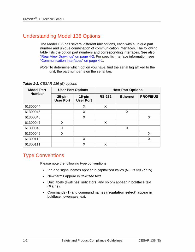
Understanding Model 136 OptionsThe Model 136 has several different unit options, each with a unique part number and unique combination of communication interfaces. The following table lists the option part numbers and corresponding interfaces. See also “Rear View Drawings” on page 4-2. For specific interface information, see “Communication Interfaces” on page 4-1.
Note: To determine which option you have, find the serial tag affixed to the unit; the part number is on the serial tag.
Type ConventionsPlease note the following type conventions:
• Pin and signal names appear in capitalized italics (RF POWER ON).
• New terms appear in italicized text.
• Unit labels (switches, indicators, and so on) appear in boldface text (Mains).
• Commands (1) and command names (regulation select) appear in boldface, lowercase text.
Table 1-1. CESAR 136 (E) options
Model Part Number
User Port Options Host Port Options
25-pin User Port
15-pin User Port
RS-232 Ethernet PROFIBUS
61300044 X X61300045 X X61300046 X X61300047 X X61300048 X X61300049 X X61300110 X X61300111 X X
1-2 Safety and Product Compliance Guidelines CESAR 136 (E)
CESAR™ 136 Generator
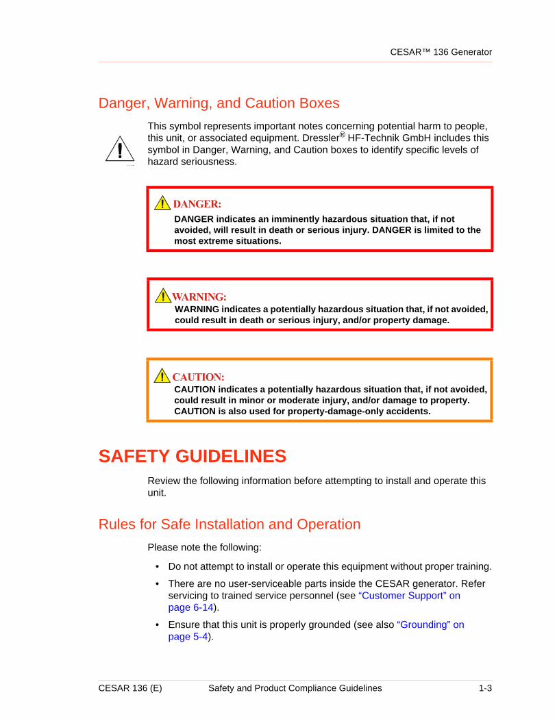
Danger, Warning, and Caution BoxesThis symbol represents important notes concerning potential harm to people, this unit, or associated equipment. Dressler® HF-Technik GmbH includes this symbol in Danger, Warning, and Caution boxes to identify specific levels of hazard seriousness.
SAFETY GUIDELINESReview the following information before attempting to install and operate this unit.
Rules for Safe Installation and OperationPlease note the following:
• Do not attempt to install or operate this equipment without proper training.
• There are no user-serviceable parts inside the CESAR generator. Refer servicing to trained service personnel (see “Customer Support” on page 6-14).
• Ensure that this unit is properly grounded (see also “Grounding” on page 5-4).
DANGER indicates an imminently hazardous situation that, if not avoided, will result in death or serious injury. DANGER is limited to the most extreme situations.
WARNING indicates a potentially hazardous situation that, if not avoided, could result in death or serious injury, and/or property damage.
CAUTION indicates a potentially hazardous situation that, if not avoided, could result in minor or moderate injury, and/or damage to property. CAUTION is also used for property-damage-only accidents.
CESAR 136 (E) Safety and Product Compliance Guidelines 1-3
Dressler® HF-Technik GmbH
• Ensure that all cables are properly connected (see also “CESAR Generator User Port Options” on page 4-11 and “CESAR Generator Host Port Options” on page 4-43).
• Verify that input line voltage and current capacity are within specifications before turning on the power supplies (see “Electrical Specifications” on page 3-4).
• Use proper electrostatic discharge (ESD) precautions.
• Always be careful around this equipment.
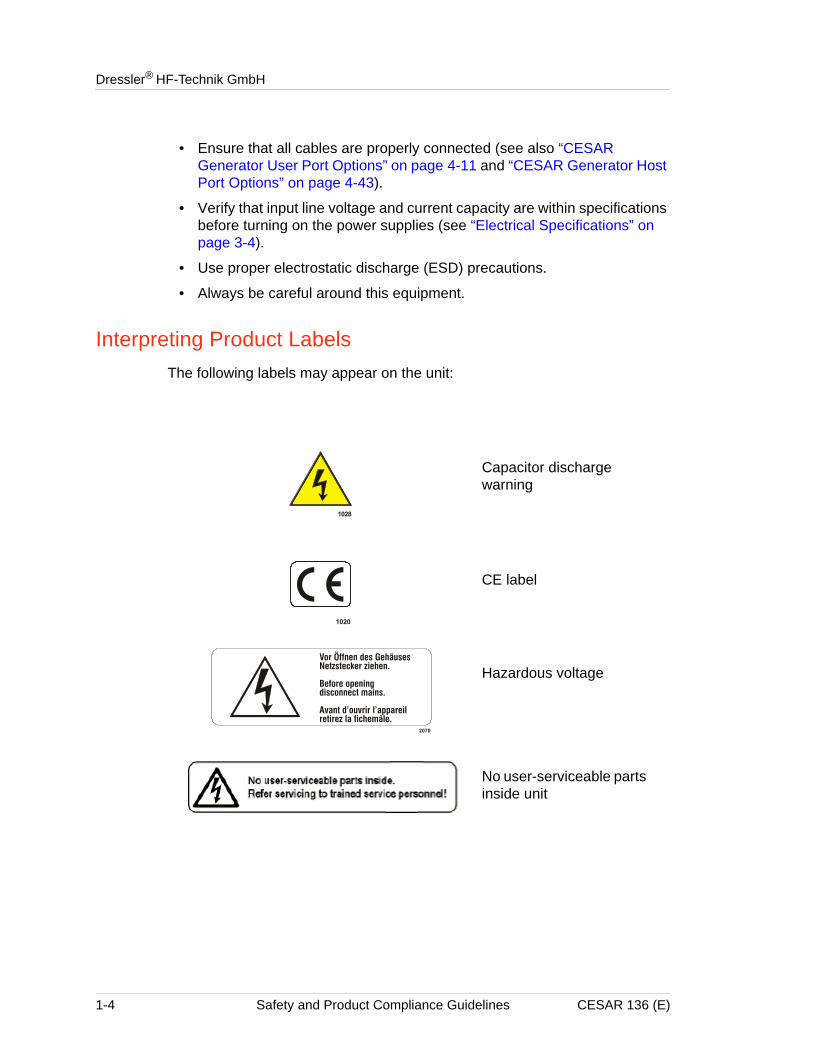
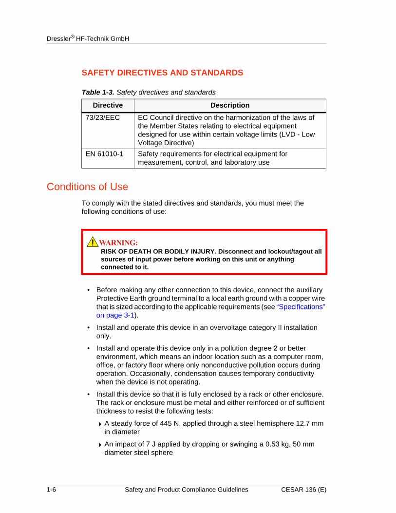
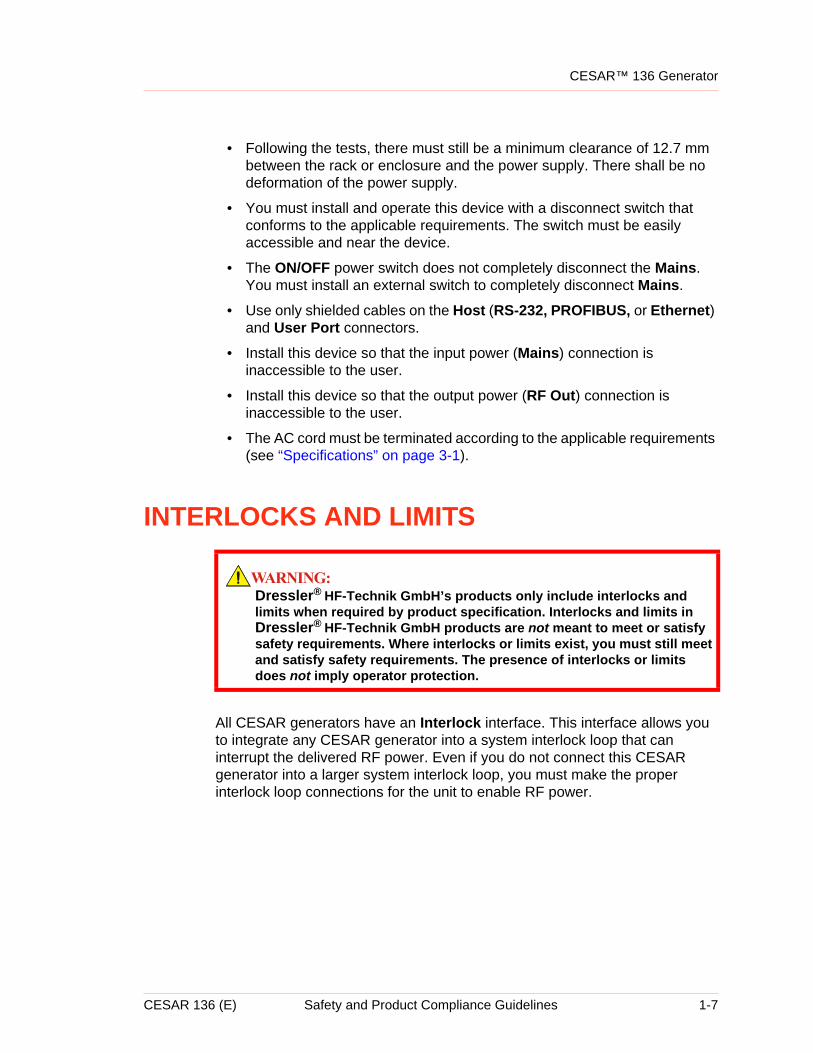
Interpreting Product LabelsThe following labels may appear on the unit:
Capacitor discharge warning
CE label
Hazardous voltage
No user-serviceable parts inside unit
1-4 Safety and Product Compliance Guidelines CESAR 136 (E)
CESAR™ 136 Generator
PRODUCT COMPLIANCEThe following sections include information about unit compliance and certification, including the conditions of use required to be in compliance with the standards and directives.
Product CertificationCertain options of this product are certified by:
• CE marking, self addressed by Dressler Compliance Engineering
• EMC measurements, verified by Competent Body Product Services
For more information, refer to the letter of conformance (US) or declaration of conformity (EU) accompanying the product.
Safety and Compliance Directives and StandardsCertain options of this unit have been tested for and comply with the following electromagnetic compatibility (EMC) and safety directives and standards.
Note: This device must be installed and used only in compliance with the directives and standards listed in addition to VDE 0113, EN 60204 (IEC 60204), and applicable requirements.
ELECTROMAGNETIC COMPATIBILITY (EMC) DIRECTIVES AND STANDARDS
Table 1-2. Electromagnetic compatibility (EMC) directives and standards
Directive Description89/336/EEC EC Council directive on the approximation of the laws of
the Member States relating to electromagnetic compatibility (EMC Directive)
47 CFRPart 18
Code of Federal Regulations—Limits and methods of measurement of radio interference characteristics of industrial, scientific, and medical equipment
EN 55011 Limits and methods of measurement of radio disturbance characteristics of industrial, scientific, medical (ISM) radio frequency equipment (Class A, Group 2) (CISPR 11)
EN 61000-6-2 Electromagnetic Compatibility (generic immunity standard— industrial)
CESAR 136 (E) Safety and Product Compliance Guidelines 1-5
Dressler® HF-Technik GmbH
SAFETY DIRECTIVES AND STANDARDS
Conditions of UseTo comply with the stated directives and standards, you must meet the following conditions of use:
• Before making any other connection to this device, connect the auxiliary Protective Earth ground terminal to a local earth ground with a copper wire that is sized according to the applicable requirements (see “Specifications” on page 3-1).
• Install and operate this device in an overvoltage category II installation only.
• Install and operate this device only in a pollution degree 2 or better environment, which means an indoor location such as a computer room, office, or factory floor where only nonconductive pollution occurs during operation. Occasionally, condensation causes temporary conductivity when the device is not operating.
• Install this device so that it is fully enclosed by a rack or other enclosure. The rack or enclosure must be metal and either reinforced or of sufficient thickness to resist the following tests:
4A steady force of 445 N, applied through a steel hemisphere 12.7 mm in diameter
4An impact of 7 J applied by dropping or swinging a 0.53 kg, 50 mm diameter steel sphere
Table 1-3. Safety directives and standards
Directive Description73/23/EEC EC Council directive on the harmonization of the laws of
the Member States relating to electrical equipment designed for use within certain voltage limits (LVD - Low Voltage Directive)
EN 61010-1 Safety requirements for electrical equipment for measurement, control, and laboratory use
RISK OF DEATH OR BODILY INJURY. Disconnect and lockout/tagout all sources of input power before working on this unit or anything connected to it.
1-6 Safety and Product Compliance Guidelines CESAR 136 (E)
CESAR™ 136 Generator
• Following the tests, there must still be a minimum clearance of 12.7 mm between the rack or enclosure and the power supply. There shall be no deformation of the power supply.
• You must install and operate this device with a disconnect switch that conforms to the applicable requirements. The switch must be easily accessible and near the device.
• The ON/OFF power switch does not completely disconnect the Mains. You must install an external switch to completely disconnect Mains.
• Use only shielded cables on the Host (RS-232, PROFIBUS, or Ethernet) and User Port connectors.
• Install this device so that the input power (Mains) connection is inaccessible to the user.
• Install this device so that the output power (RF Out) connection is inaccessible to the user.
• The AC cord must be terminated according to the applicable requirements (see “Specifications” on page 3-1).
INTERLOCKS AND LIMITS
All CESAR generators have an Interlock interface. This interface allows you to integrate any CESAR generator into a system interlock loop that can interrupt the delivered RF power. Even if you do not connect this CESAR generator into a larger system interlock loop, you must make the proper interlock loop connections for the unit to enable RF power.
Dressler® HF-Technik GmbH’s products only include interlocks and limits when required by product specification. Interlocks and limits in Dressler® HF-Technik GmbH products are not meant to meet or satisfy safety requirements. Where interlocks or limits exist, you must still meet and satisfy safety requirements. The presence of interlocks or limits does not imply operator protection.
CESAR 136 (E) Safety and Product Compliance Guidelines 1-7
Dressler® HF-Technik GmbH
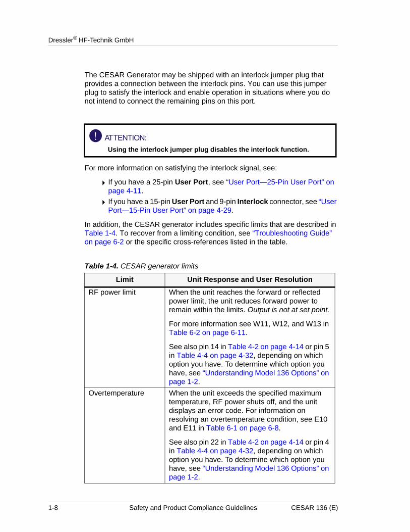
The CESAR Generator may be shipped with an interlock jumper plug that provides a connection between the interlock pins. You can use this jumper plug to satisfy the interlock and enable operation in situations where you do not intend to connect the remaining pins on this port.
For more information on satisfying the interlock signal, see:
4 If you have a 25-pin User Port, see “User Port—25-Pin User Port” on page 4-11.
4 If you have a 15-pin User Port and 9-pin Interlock connector, see “User Port—15-Pin User Port” on page 4-29.
In addition, the CESAR generator includes specific limits that are described in Table 1-4. To recover from a limiting condition, see “Troubleshooting Guide” on page 6-2 or the specific cross-references listed in the table.
Using the interlock jumper plug disables the interlock function.
Table 1-4. CESAR generator limits
Limit Unit Response and User ResolutionRF power limit When the unit reaches the forward or reflected
power limit, the unit reduces forward power to remain within the limits. Output is not at set point.
For more information see W11, W12, and W13 in Table 6-2 on page 6-11.
See also pin 14 in Table 4-2 on page 4-14 or pin 5 in Table 4-4 on page 4-32, depending on which option you have. To determine which option you have, see “Understanding Model 136 Options” on page 1-2.
Overtemperature When the unit exceeds the specified maximum temperature, RF power shuts off, and the unit displays an error code. For information on resolving an overtemperature condition, see E10 and E11 in Table 6-1 on page 6-8.
See also pin 22 in Table 4-2 on page 4-14 or pin 4 in Table 4-4 on page 4-32, depending on which option you have. To determine which option you have, see “Understanding Model 136 Options” on page 1-2.
1-8 Safety and Product Compliance Guidelines CESAR 136 (E)
CESAR™ 136 Generator
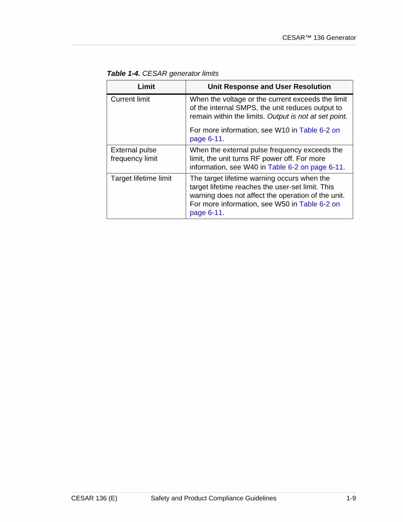
Current limit When the voltage or the current exceeds the limit of the internal SMPS, the unit reduces output to remain within the limits. Output is not at set point.
For more information, see W10 in Table 6-2 on page 6-11.
External pulse frequency limit
When the external pulse frequency exceeds the limit, the unit turns RF power off. For more information, see W40 in Table 6-2 on page 6-11.
Target lifetime limit The target lifetime warning occurs when the target lifetime reaches the user-set limit. This warning does not affect the operation of the unit. For more information, see W50 in Table 6-2 on page 6-11.
Table 1-4. CESAR generator limits
Limit Unit Response and User Resolution
CESAR 136 (E) Safety and Product Compliance Guidelines 1-9
Dressler® HF-Technik GmbH
1-10 Safety and Product Compliance Guidelines CESAR 136 (E)
ChapterCESAR™ 136 Generator
Chapter
2
Product Overview and TheoryDESCRIPTIONCESAR™ 136 Generators are Class E Switched Mode Amplifiers for Radio Frequency (CESAR), a new generation of versatile RF power supplies for semiconductor production, and general plasma processing. This 13.56 MHz generator employs parallel excited circuitry in a compact, 19" rack-mountable designs. Typical applications include sputtering, reactive ion etching, RF bias, plasma polymerization, plasma surface treatment, and CO2 laser systems.
The CESAR generator incorporates advanced switch mode technology. This highly efficient, resonant switching concept results in reduced energy costs, reduced downtimes, and a longer lifetime for the unit.
Designed to regulate power into a broad range of output impedances, the CESAR generator can operate in forward, load, or external power regulation mode (see “Setting Regulation Mode” on page 5-15).
Both manual and automatic tuning control support operation into a fixed impedance matching network, which simplifies system complexity, increases reliability, and improves process-to-process repeatability (see “Controlling the Matchbox” on page 5-20).
You can control the CESAR generator remotely through an analog User Port (see “CESAR Generator User Port Options” on page 4-11) or a serial Host port (see “CESAR Generator Host Port Options” on page 4-43). The front panel features a liquid crystal display (LCD) with an easy-to-use menu that includes widely programmable pulse functions, a target lifetime counter, and submenus to customize your own recipes, reflected power settings, and Variomatch settings (when the generator is connected to a Variomatch unit). In addition, you may control RF power and match settings using the front panel controls. For operation instructions, see “First-Time Operation” on page 5-10 and “Normal Operation” on page 5-15.
The CESAR generator operates from a 230 VAC, 50/60 Hz power source. The CESAR generator is air-cooled and has all power and interface-port connections at the rear of the generator (see “Rear View Drawings” on page 4-2).
CESAR 136 (E) Product Overview and Theory 2-1
Dressler® HF-Technik GmbH
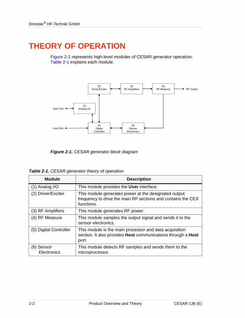
THEORY OF OPERATIONFigure 2-1 represents high-level modules of CESAR generator operation; Table 2-1 explains each module.
Figure 2-1. CESAR generator block diagram
(2)Driver/Exciter
(1)Analog I/O
(5)Digital
Controller
(3)RF Amplifiers
(4)RF Measure
(6)Sensor
Electronics
User Port
Host Port
RF Output
Table 2-1. CESAR generator theory of operation
Module Description(1) Analog I/O This module provides the User interface.(2) Driver/Exciter This module generates power at the designated output
frequency to drive the main RF sections and contains the CEX functions.
(3) RF Amplifiers This module generates RF power.(4) RF Measure This module samples the output signal and sends it to the
sensor electronics.(5) Digital Controller This module is the main processor and data acquisition
section. It also provides Host communications through a Host port.
(6) Sensor Electronics
This module detects RF samples and sends them to the microprocessor.
2-2 Product Overview and Theory CESAR 136 (E)
ChapterCESAR™ 136 Generator
Chapter
3
SpecificationsPHYSICAL SPECIFICATIONSThe following sections describe the dimensions and physical specifications of the CESAR generator. All generator specifications are also available online; please visit http://www.dressler.com/products/generators.
• “Unit Dimensions” on page 3-2
• “Physical Specifications Table” on page 3-3
CESAR 136 (E) Specifications 3-1
Dressler® HF-Technik GmbH
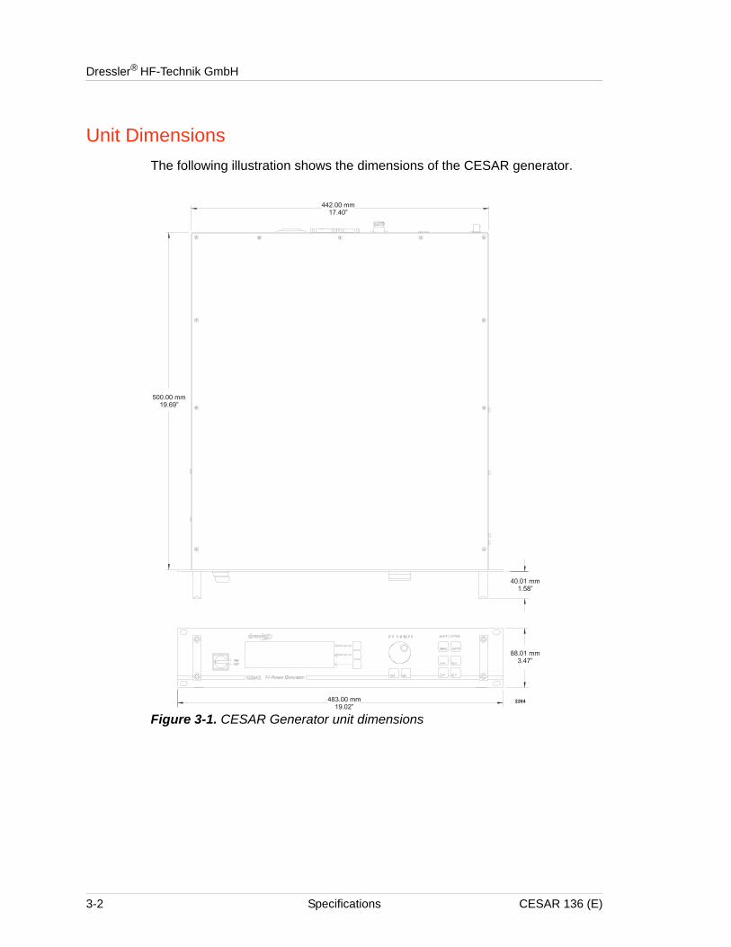
Unit DimensionsThe following illustration shows the dimensions of the CESAR generator.
Figure 3-1. CESAR Generator unit dimensions
3-2 Specifications CESAR 136 (E)
CESAR™ 136 Generator
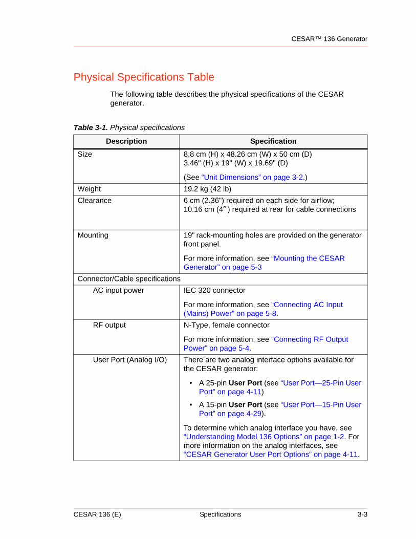
Physical Specifications TableThe following table describes the physical specifications of the CESAR generator.
Table 3-1. Physical specifications
Description SpecificationSize 8.8 cm (H) x 48.26 cm (W) x 50 cm (D)
3.46" (H) x 19" (W) x 19.69" (D)
(See “Unit Dimensions” on page 3-2.)Weight 19.2 kg (42 lb)Clearance 6 cm (2.36") required on each side for airflow;
10.16 cm (4″ ) required at rear for cable connections
Mounting 19" rack-mounting holes are provided on the generator front panel.
For more information, see “Mounting the CESAR Generator” on page 5-3
Connector/Cable specificationsAC input power IEC 320 connector
For more information, see “Connecting AC Input (Mains) Power” on page 5-8.
RF output N-Type, female connector
For more information, see “Connecting RF Output Power” on page 5-4.
User Port (Analog I/O) There are two analog interface options available for the CESAR generator:
• A 25-pin User Port (see “User Port—25-Pin User Port” on page 4-11)
• A 15-pin User Port (see “User Port—15-Pin User Port” on page 4-29).
To determine which analog interface you have, see “Understanding Model 136 Options” on page 1-2. For more information on the analog interfaces, see “CESAR Generator User Port Options” on page 4-11.
CESAR 136 (E) Specifications 3-3
Dressler® HF-Technik GmbH
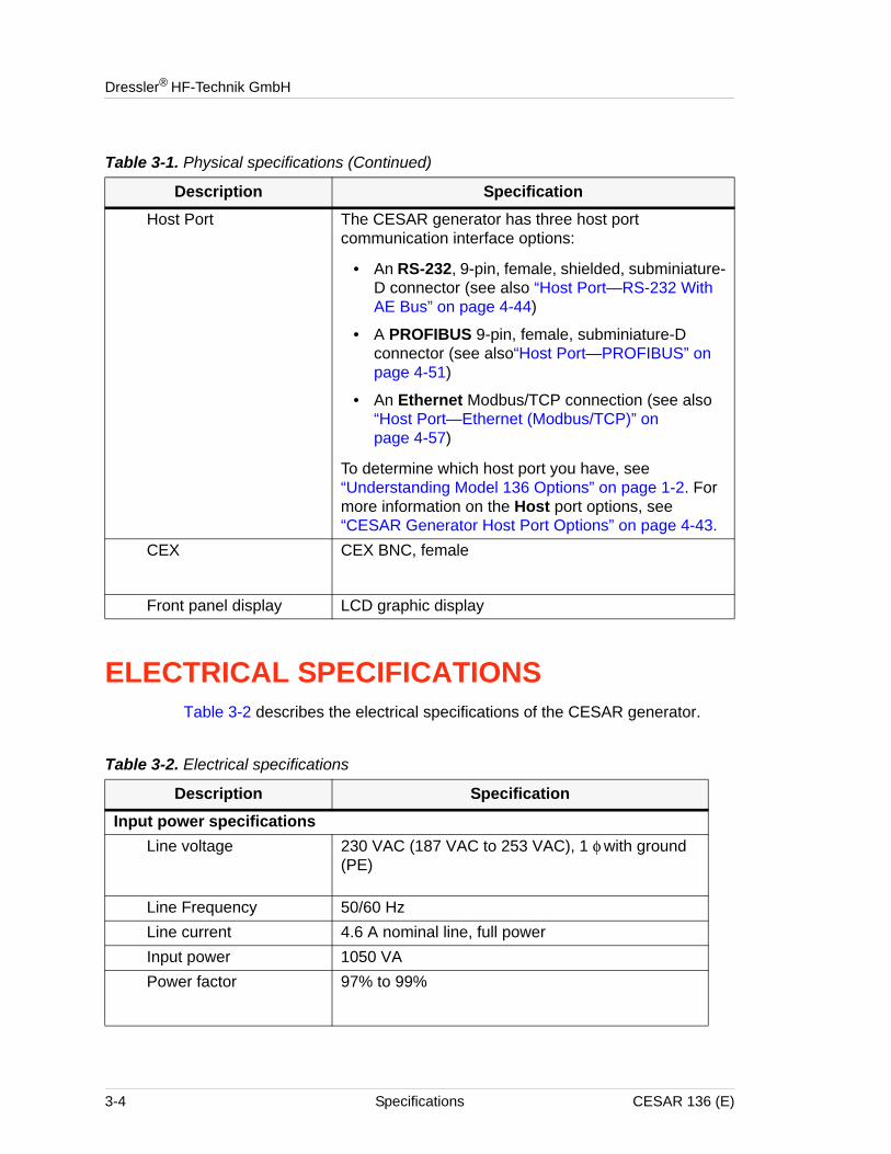
ELECTRICAL SPECIFICATIONSTable 3-2 describes the electrical specifications of the CESAR generator.
Host Port The CESAR generator has three host port communication interface options:
• An RS-232, 9-pin, female, shielded, subminiature-D connector (see also “Host Port—RS-232 With AE Bus” on page 4-44)
• A PROFIBUS 9-pin, female, subminiature-D connector (see also“Host Port—PROFIBUS” on page 4-51)
• An Ethernet Modbus/TCP connection (see also “Host Port—Ethernet (Modbus/TCP)” on page 4-57)
To determine which host port you have, see “Understanding Model 136 Options” on page 1-2. For more information on the Host port options, see “CESAR Generator Host Port Options” on page 4-43.
CEX CEX BNC, female
Front panel display LCD graphic display
Table 3-1. Physical specifications (Continued)
Description Specification
Table 3-2. Electrical specifications
Description SpecificationInput power specifications
Line voltage 230 VAC (187 VAC to 253 VAC), 1 φ with ground (PE)
Line Frequency 50/60 HzLine current 4.6 A nominal line, full powerInput power 1050 VAPower factor 97% to 99%
3-4 Specifications CESAR 136 (E)
CESAR™ 136 Generator
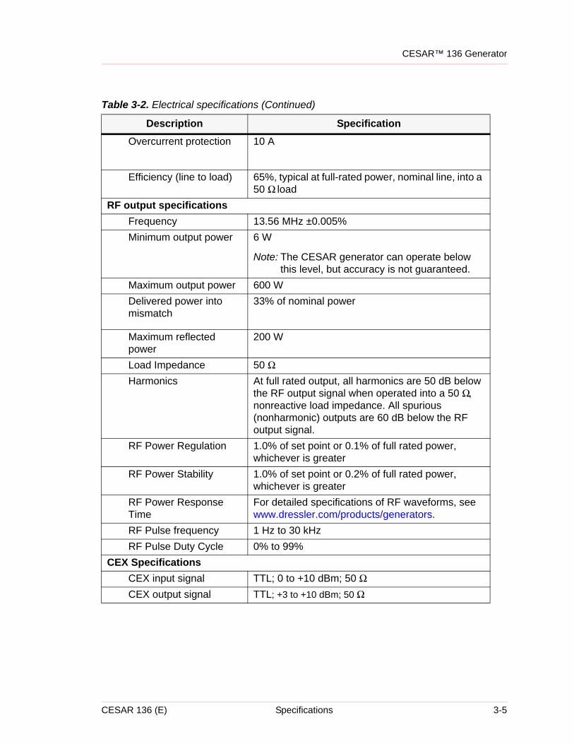
Overcurrent protection 10 A
Efficiency (line to load) 65%, typical at full-rated power, nominal line, into a 50 Ω load
RF output specificationsFrequency 13.56 MHz ±0.005%Minimum output power 6 W
Note: The CESAR generator can operate below this level, but accuracy is not guaranteed.
Maximum output power 600 WDelivered power into mismatch
33% of nominal power
Maximum reflected power
200 W
Load Impedance 50 ΩHarmonics At full rated output, all harmonics are 50 dB below
the RF output signal when operated into a 50 Ω, nonreactive load impedance. All spurious (nonharmonic) outputs are 60 dB below the RF output signal.
RF Power Regulation 1.0% of set point or 0.1% of full rated power, whichever is greater
RF Power Stability 1.0% of set point or 0.2% of full rated power, whichever is greater
RF Power Response Time
For detailed specifications of RF waveforms, see www.dressler.com/products/generators.
RF Pulse frequency 1 Hz to 30 kHzRF Pulse Duty Cycle 0% to 99%
CEX SpecificationsCEX input signal TTL; 0 to +10 dBm; 50 ΩCEX output signal TTL; +3 to +10 dBm; 50 Ω
Table 3-2. Electrical specifications (Continued)
Description Specification
CESAR 136 (E) Specifications 3-5
Dressler® HF-Technik GmbH
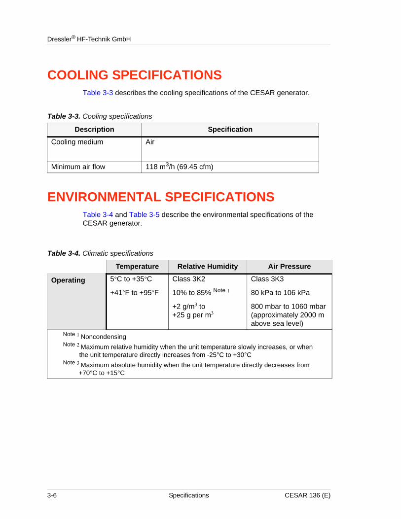
COOLING SPECIFICATIONSTable 3-3 describes the cooling specifications of the CESAR generator.
ENVIRONMENTAL SPECIFICATIONSTable 3-4 and Table 3-5 describe the environmental specifications of the CESAR generator.
Table 3-3. Cooling specifications
Description SpecificationCooling medium Air
Minimum air flow 118 m3/h (69.45 cfm)
Table 3-4. Climatic specifications
Temperature Relative Humidity Air Pressure
Operating 5°C to +35°C
+41°F to +95°F
Class 3K2
10% to 85% Note 1
+2 g/m3 to +25 g per m3
Class 3K3
80 kPa to 106 kPa
800 mbar to 1060 mbar(approximately 2000 m above sea level)
Note 1 NoncondensingNote 2 Maximum relative humidity when the unit temperature slowly increases, or when
the unit temperature directly increases from -25°C to +30°CNote 3 Maximum absolute humidity when the unit temperature directly decreases from
+70°C to +15°C
3-6 Specifications CESAR 136 (E)
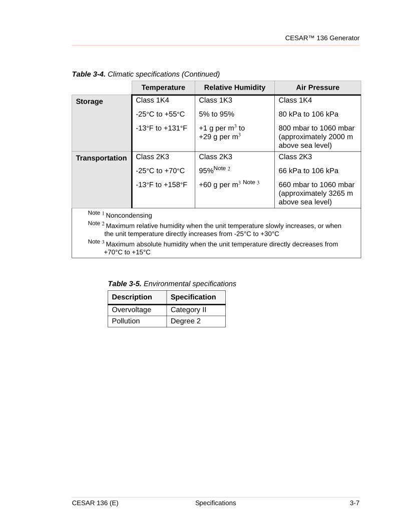
CESAR™ 136 Generator
Storage Class 1K4
-25°C to +55°C
-13°F to +131°F
Class 1K3
5% to 95%
+1 g per m3 to +29 g per m3
Class 1K4
80 kPa to 106 kPa
800 mbar to 1060 mbar(approximately 2000 m above sea level)
Transportation Class 2K3
-25°C to +70°C
-13°F to +158°F
Class 2K3
95%Note 2
+60 g per m3 Note 3
Class 2K3
66 kPa to 106 kPa
660 mbar to 1060 mbar(approximately 3265 m above sea level)
Table 3-4. Climatic specifications (Continued)
Temperature Relative Humidity Air Pressure
Note 1 NoncondensingNote 2 Maximum relative humidity when the unit temperature slowly increases, or when
the unit temperature directly increases from -25°C to +30°CNote 3 Maximum absolute humidity when the unit temperature directly decreases from
+70°C to +15°C
Table 3-5. Environmental specifications
Description SpecificationOvervoltage Category IIPollution Degree 2
CESAR 136 (E) Specifications 3-7
Dressler® HF-Technik GmbH
3-8 Specifications CESAR 136 (E)
ChapterCESAR™ 136 Generator
Chapter
4
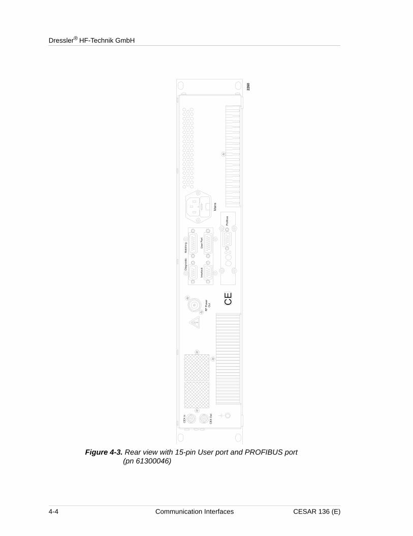
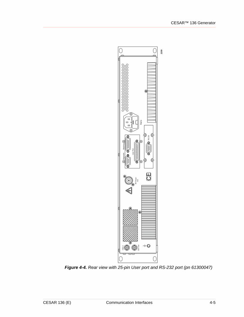
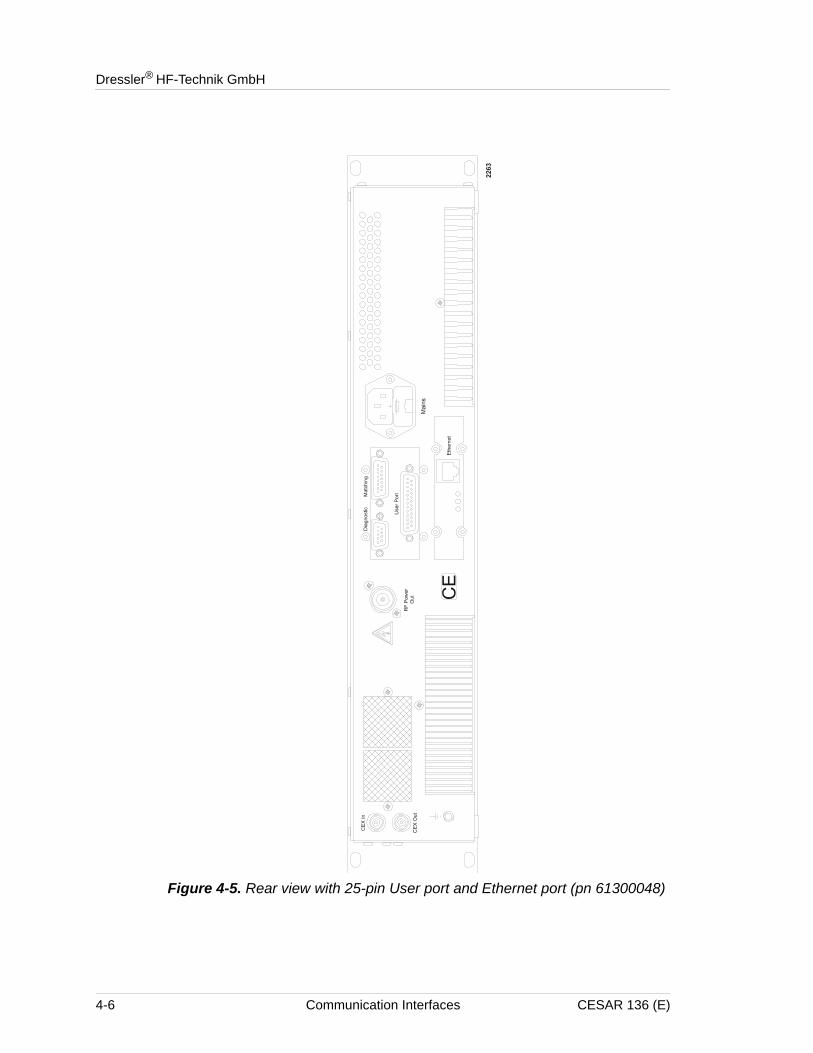
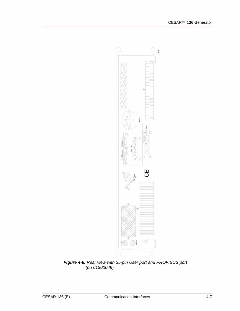
Communication InterfacesThe CESAR generator has several possible interface options. The following figures illustrate the available interface combinations for the Model 136 CESAR generator. The sections that follow describe each interface.
Note: To determine which interface options you have, see “Understanding Model 136 Options” on page 1-2.
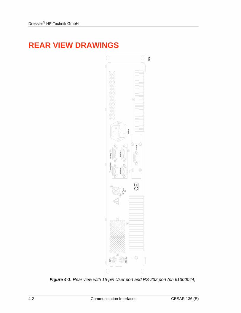
• For an illustration of the “Rear view with 15-pin User port and RS-232 port (pn 61300044)”, see Figure 4-1 on page 4-2.
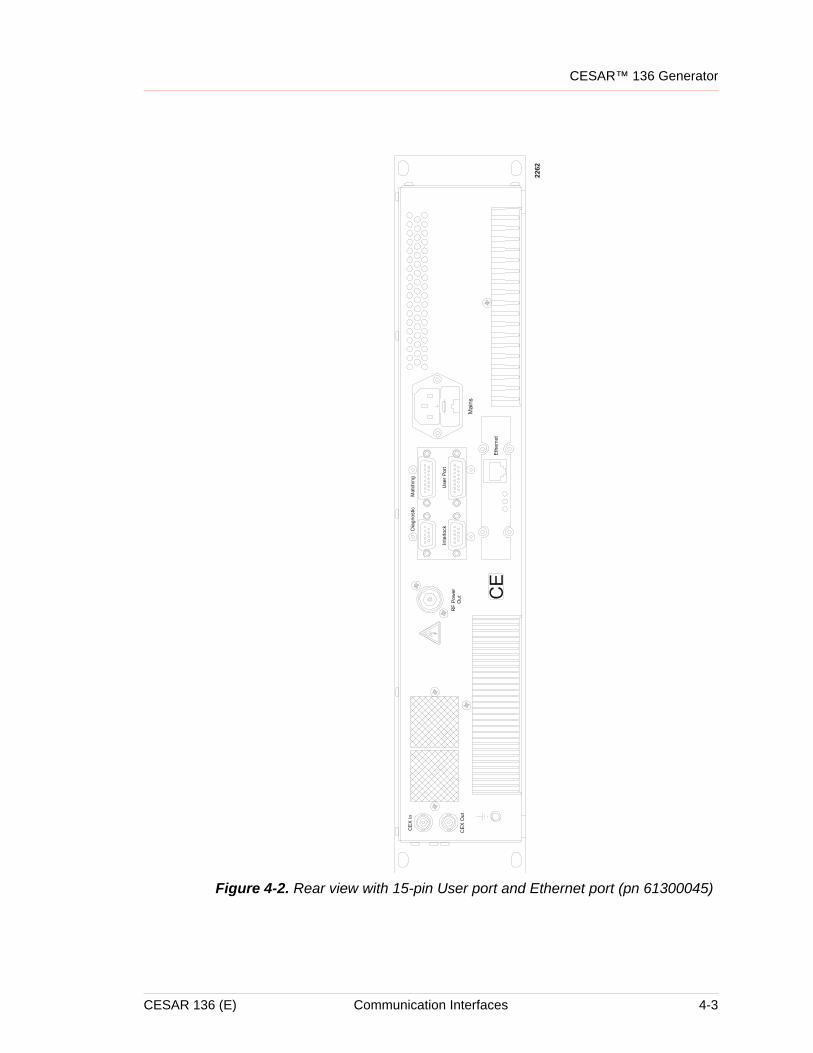
• For an illustration of the “Rear view with 15-pin User port and Ethernet port (pn 61300045)”, see Figure 4-2 on page 4-3.
• For an illustration of the “Rear view with 15-pin User port and PROFIBUS port (pn 61300046)”, see Figure 4-3 on page 4-4.
• For an illustration of the “Rear view with 25-pin User port and RS-232 port (pn 61300047)”, see Figure 4-4 on page 4-5.
• For an illustration of the “Rear view with 25-pin User port and Ethernet port (pn 61300048)”, see Figure 4-5 on page 4-6.
• For an illustration of the “Rear view with 25-pin User port and PROFIBUS port (pn 61300049)”, see Figure 4-6 on page 4-7.
• For an illustration of the “Rear view with 15-pin User Port and PROFIBUS port (pn 61300110)”, see
CESAR 136 (E) Communication Interfaces 4-1
Dressler® HF-Technik GmbH
REAR VIEW DRAWINGS
Figure 4-1. Rear view with 15-pin User port and RS-232 port (pn 61300044)
4-2 Communication Interfaces CESAR 136 (E)
CESAR™ 136 Generator
Figure 4-2. Rear view with 15-pin User port and Ethernet port (pn 61300045)
CESAR 136 (E) Communication Interfaces 4-3
Dressler® HF-Technik GmbH
Figure 4-3. Rear view with 15-pin User port and PROFIBUS port (pn 61300046)
4-4 Communication Interfaces CESAR 136 (E)
CESAR™ 136 Generator
Figure 4-4. Rear view with 25-pin User port and RS-232 port (pn 61300047)
CESAR 136 (E) Communication Interfaces 4-5
Dressler® HF-Technik GmbH
Figure 4-5. Rear view with 25-pin User port and Ethernet port (pn 61300048)
4-6 Communication Interfaces CESAR 136 (E)
CESAR™ 136 Generator
Figure 4-6. Rear view with 25-pin User port and PROFIBUS port (pn 61300049)
CESAR 136 (E) Communication Interfaces 4-7
Dressler® HF-Technik GmbH
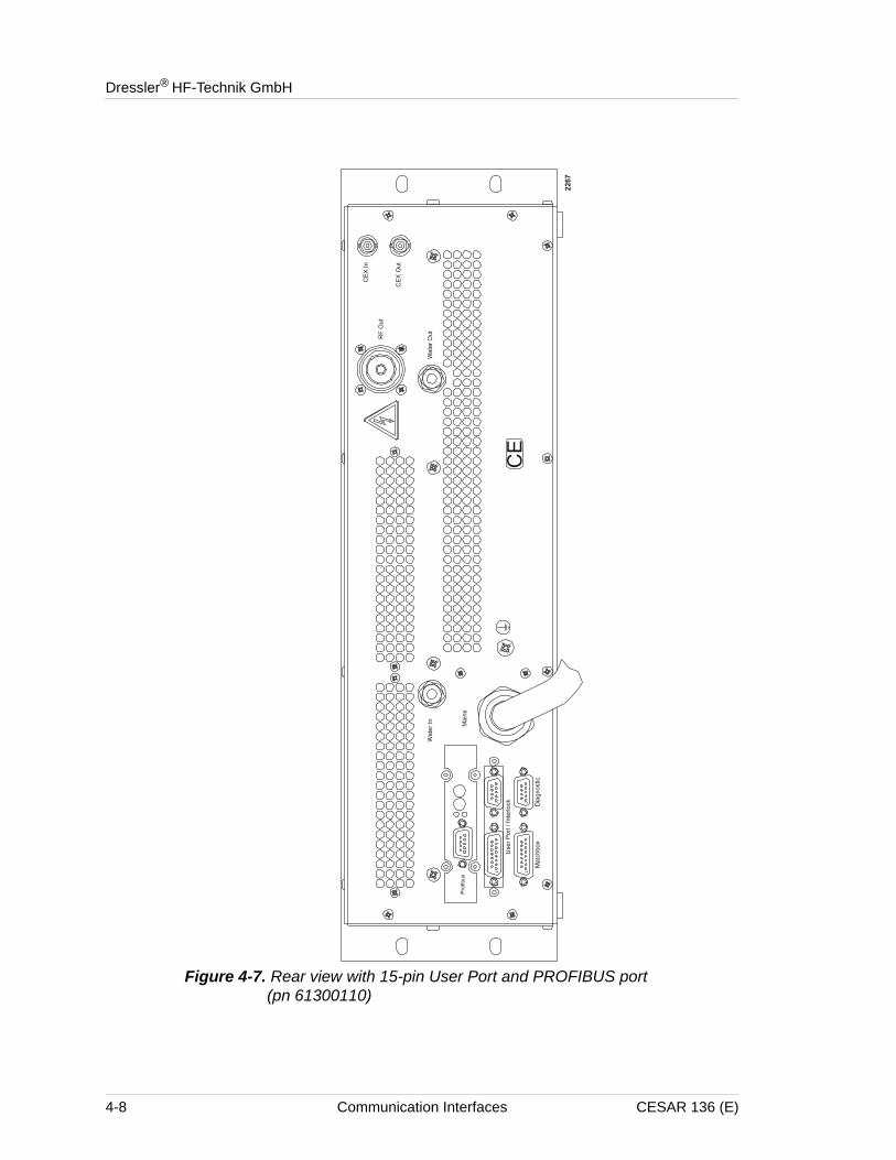
Figure 4-7. Rear view with 15-pin User Port and PROFIBUS port (pn 61300110)
4-8 Communication Interfaces CESAR 136 (E)
CESAR™ 136 Generator
DIAGNOSTIC INTERFACEEach CESAR generator has a Diagnostic interface for use only at authorized Dressler Service Centers. Technicians can check internal commands, calibrate the unit, or flash software using this interface.
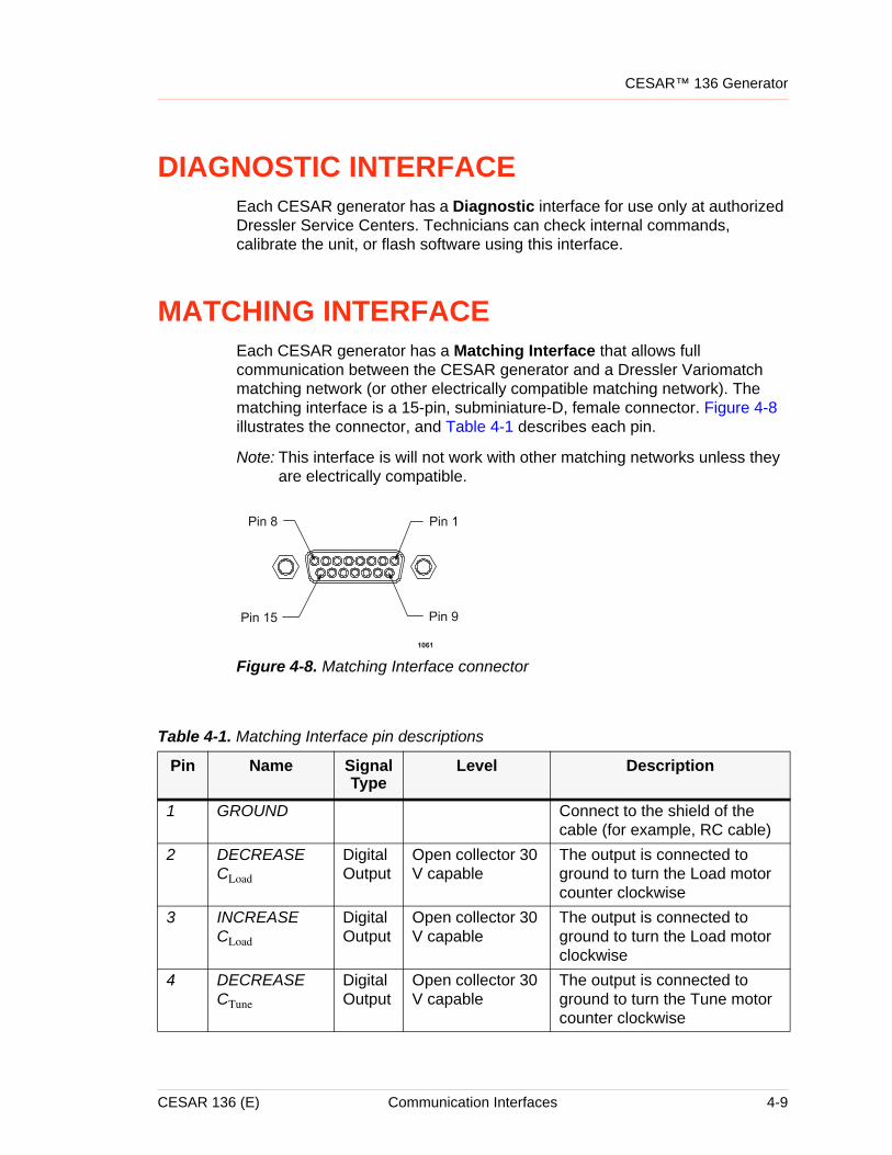
MATCHING INTERFACEEach CESAR generator has a Matching Interface that allows full communication between the CESAR generator and a Dressler Variomatch matching network (or other electrically compatible matching network). The matching interface is a 15-pin, subminiature-D, female connector. Figure 4-8 illustrates the connector, and Table 4-1 describes each pin.
Note: This interface is will not work with other matching networks unless they are electrically compatible.
Figure 4-8. Matching Interface connector
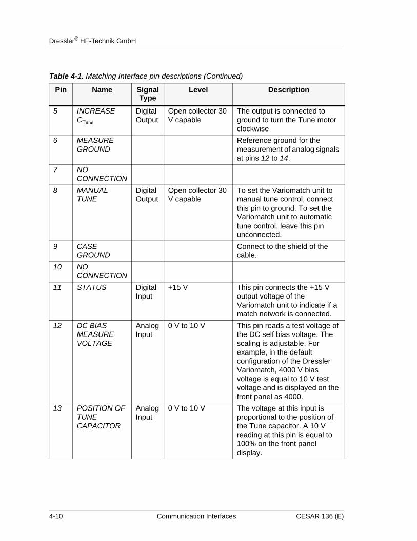
Table 4-1. Matching Interface pin descriptions
Pin Name Signal Type
Level Description
1 GROUND Connect to the shield of the cable (for example, RC cable)
2 DECREASE CLoad
Digital Output
Open collector 30 V capable
The output is connected to ground to turn the Load motor counter clockwise
3 INCREASE CLoad
Digital Output
Open collector 30 V capable
The output is connected to ground to turn the Load motor clockwise
4 DECREASE CTune
Digital Output
Open collector 30 V capable
The output is connected to ground to turn the Tune motor counter clockwise
CESAR 136 (E) Communication Interfaces 4-9
Dressler® HF-Technik GmbH
5 INCREASE CTune
Digital Output
Open collector 30 V capable
The output is connected to ground to turn the Tune motor clockwise
6 MEASURE GROUND
Reference ground for the measurement of analog signals at pins 12 to 14.
7 NO CONNECTION
8 MANUAL TUNE
Digital Output
Open collector 30 V capable
To set the Variomatch unit to manual tune control, connect this pin to ground. To set the Variomatch unit to automatic tune control, leave this pin unconnected.
9 CASE GROUND
Connect to the shield of the cable.
10 NO CONNECTION
11 STATUS Digital Input
+15 V This pin connects the +15 V output voltage of the Variomatch unit to indicate if a match network is connected.
12 DC BIAS MEASURE VOLTAGE
Analog Input
0 V to 10 V This pin reads a test voltage of the DC self bias voltage. The scaling is adjustable. For example, in the default configuration of the Dressler Variomatch, 4000 V bias voltage is equal to 10 V test voltage and is displayed on the front panel as 4000.
13 POSITION OF TUNE CAPACITOR
Analog Input
0 V to 10 V The voltage at this input is proportional to the position of the Tune capacitor. A 10 V reading at this pin is equal to 100% on the front panel display.
Table 4-1. Matching Interface pin descriptions (Continued)
Pin Name Signal Type
Level Description
4-10 Communication Interfaces CESAR 136 (E)
CESAR™ 136 Generator
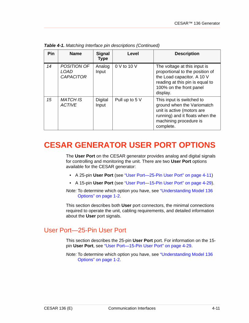
CESAR GENERATOR USER PORT OPTIONSThe User Port on the CESAR generator provides analog and digital signals for controlling and monitoring the unit. There are two User Port options available for the CESAR generator:
• A 25-pin User Port (see “User Port—25-Pin User Port” on page 4-11)
• A 15-pin User Port (see “User Port—15-Pin User Port” on page 4-29).
Note: To determine which option you have, see “Understanding Model 136 Options” on page 1-2.
This section describes both User port connectors, the minimal connections required to operate the unit, cabling requirements, and detailed information about the User port signals.
User Port—25-Pin User PortThis section describes the 25-pin User Port port. For information on the 15-pin User Port, see “User Port—15-Pin User Port” on page 4-29.
Note: To determine which option you have, see “Understanding Model 136 Options” on page 1-2.
14 POSITION OF LOAD CAPACITOR
Analog Input
0 V to 10 V The voltage at this input is proportional to the position of the Load capacitor. A 10 V reading at this pin is equal to 100% on the front panel display.
15 MATCH IS ACTIVE
Digital Input
Pull up to 5 V This input is switched to ground when the Variomatch unit is active (motors are running) and it floats when the machining procedure is complete.
Table 4-1. Matching Interface pin descriptions (Continued)
Pin Name Signal Type
Level Description
CESAR 136 (E) Communication Interfaces 4-11
Dressler® HF-Technik GmbH
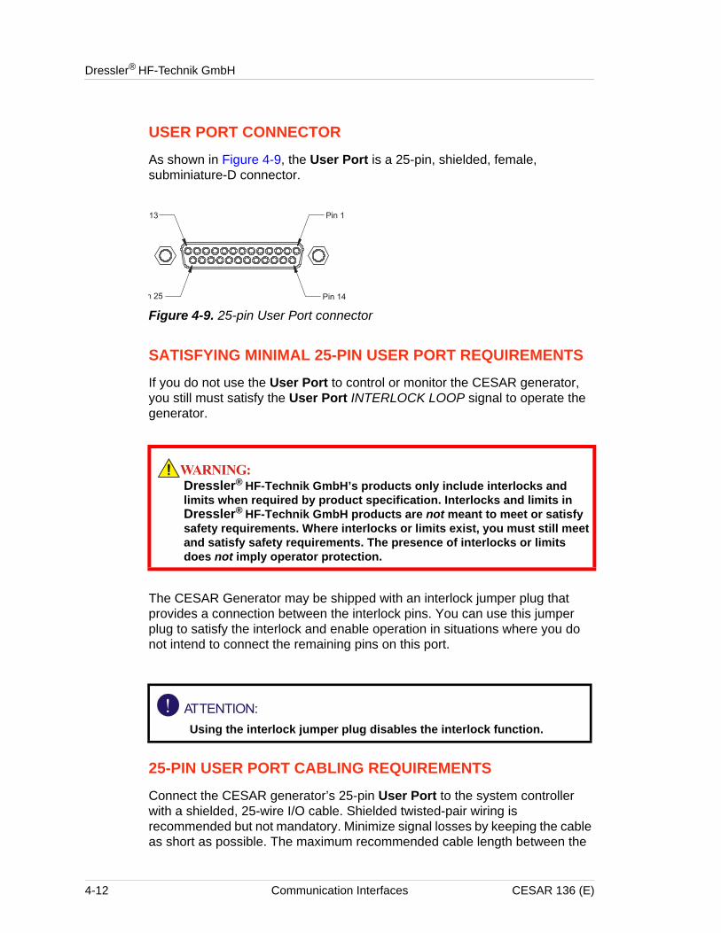
USER PORT CONNECTOR
As shown in Figure 4-9, the User Port is a 25-pin, shielded, female, subminiature-D connector.
Figure 4-9. 25-pin User Port connector
SATISFYING MINIMAL 25-PIN USER PORT REQUIREMENTS
If you do not use the User Port to control or monitor the CESAR generator, you still must satisfy the User Port INTERLOCK LOOP signal to operate the generator.
The CESAR Generator may be shipped with an interlock jumper plug that provides a connection between the interlock pins. You can use this jumper plug to satisfy the interlock and enable operation in situations where you do not intend to connect the remaining pins on this port.
25-PIN USER PORT CABLING REQUIREMENTS
Connect the CESAR generator’s 25-pin User Port to the system controller with a shielded, 25-wire I/O cable. Shielded twisted-pair wiring is recommended but not mandatory. Minimize signal losses by keeping the cable as short as possible. The maximum recommended cable length between the
Dressler® HF-Technik GmbH’s products only include interlocks and limits when required by product specification. Interlocks and limits in Dressler® HF-Technik GmbH products are not meant to meet or satisfy safety requirements. Where interlocks or limits exist, you must still meet and satisfy safety requirements. The presence of interlocks or limits does not imply operator protection.
Using the interlock jumper plug disables the interlock function.
4-12 Communication Interfaces CESAR 136 (E)
CESAR™ 136 Generator
CESAR generator and the controller is 10 meters (33 feet). Minimize interference from adjacent electrical equipment by terminating the EMI shield in the cable to the metal shells of the cable’s connectors. Additionally, you must tie the chassis of the CESAR generator to a local earth ground through an adequately sized copper grounding strap.
Note: Grounding the User Port at the CESAR generator reduces noise interference. To avoid ground loop problems, you should typically ground only one end of the User Port cable.
ACTIVATING THE 25-PIN USER PORT
To activate the 25-pin User Port control
1. Press the Program soft key.
2. Press Next until you see Device Configuration on the display.
3. Press Change.
4. Press OK until you see Control by on the right-hand side of the screen.
5. Press User Port.6. Press Execute.
CESAR 136 (E) Communication Interfaces 4-13
Dressler® HF-Technik GmbH
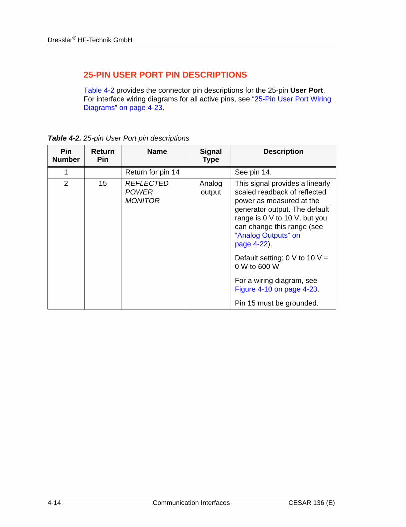
25-PIN USER PORT PIN DESCRIPTIONS
Table 4-2 provides the connector pin descriptions for the 25-pin User Port. For interface wiring diagrams for all active pins, see “25-Pin User Port Wiring Diagrams” on page 4-23.
Table 4-2. 25-pin User Port pin descriptions
Pin Number
Return Pin
Name Signal Type
Description
1 Return for pin 14 See pin 14.2 15 REFLECTED
POWER MONITOR
Analog output
This signal provides a linearly scaled readback of reflected power as measured at the generator output. The default range is 0 V to 10 V, but you can change this range (see “Analog Outputs” on page 4-22).
Default setting: 0 V to 10 V = 0 W to 600 W
For a wiring diagram, see Figure 4-10 on page 4-23.
Pin 15 must be grounded.
4-14 Communication Interfaces CESAR 136 (E)
CESAR™ 136 Generator
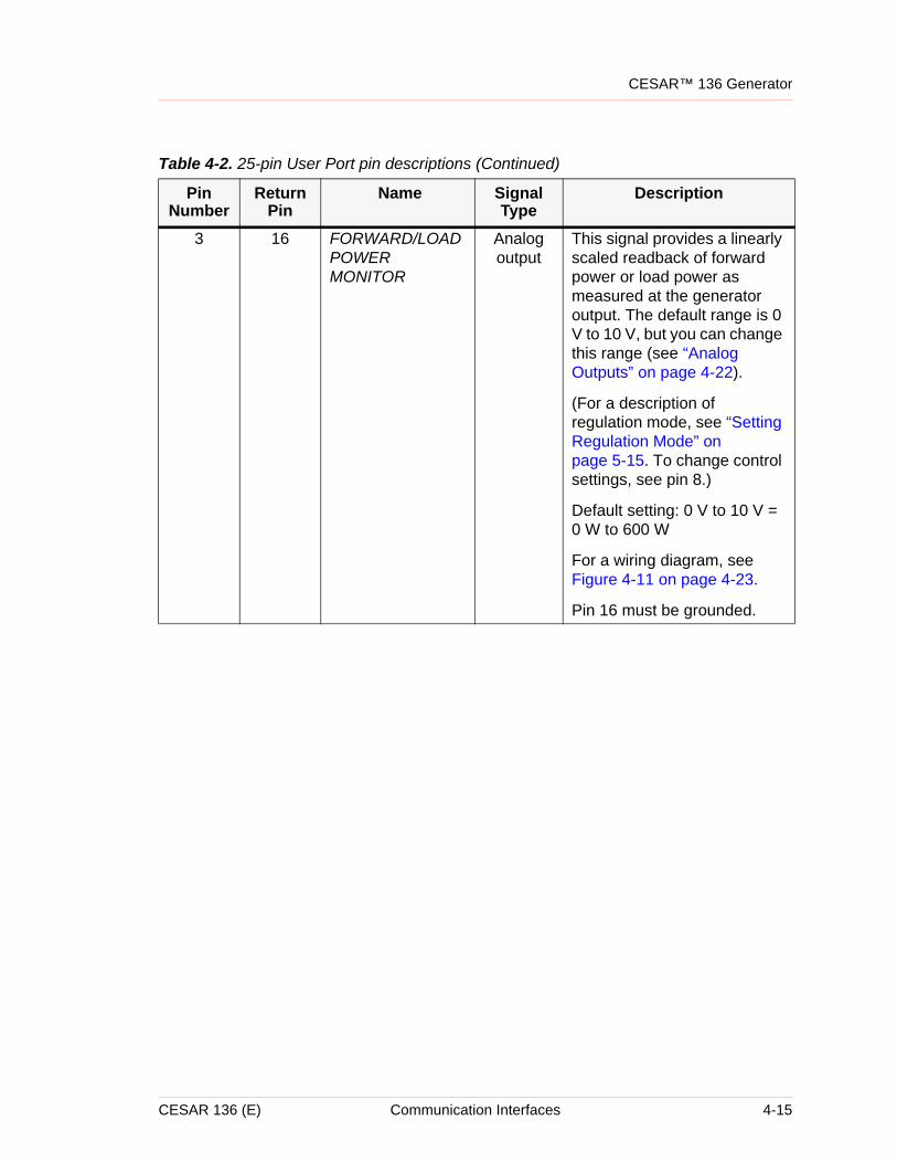
3 16 FORWARD/LOAD POWER MONITOR
Analog output
This signal provides a linearly scaled readback of forward power or load power as measured at the generator output. The default range is 0 V to 10 V, but you can change this range (see “Analog Outputs” on page 4-22).
(For a description of regulation mode, see “Setting Regulation Mode” on page 5-15. To change control settings, see pin 8.)
Default setting: 0 V to 10 V = 0 W to 600 W
For a wiring diagram, see Figure 4-11 on page 4-23.
Pin 16 must be grounded.
Table 4-2. 25-pin User Port pin descriptions (Continued)
Pin Number
Return Pin
Name Signal Type
Description
CESAR 136 (E) Communication Interfaces 4-15
Dressler® HF-Technik GmbH
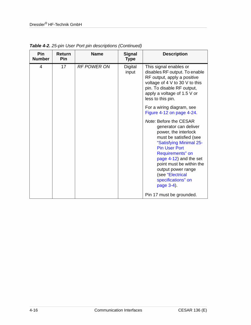
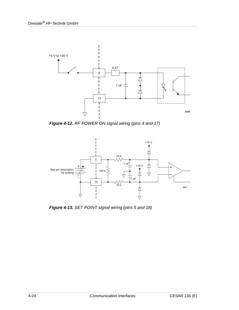
4 17 RF POWER ON Digital input
This signal enables or disables RF output. To enable RF output, apply a positive voltage of 4 V to 30 V to this pin. To disable RF output, apply a voltage of 1.5 V or less to this pin.
For a wiring diagram, see Figure 4-12 on page 4-24.
Note: Before the CESAR generator can deliver power, the interlock must be satisfied (see “Satisfying Minimal 25-Pin User Port Requirements” on page 4-12) and the set point must be within the output power range (see “Electrical specifications” on page 3-4).
Pin 17 must be grounded.
Table 4-2. 25-pin User Port pin descriptions (Continued)
Pin Number
Return Pin
Name Signal Type
Description
4-16 Communication Interfaces CESAR 136 (E)
CESAR™ 136 Generator
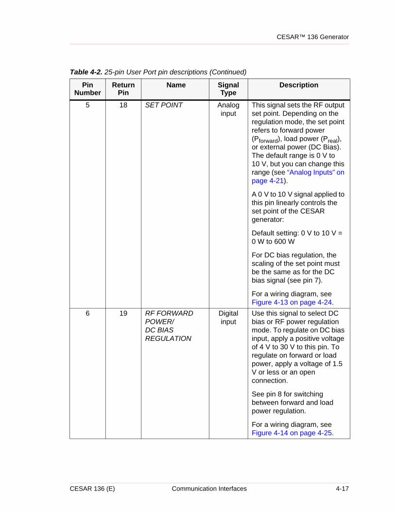
5 18 SET POINT Analog input
This signal sets the RF output set point. Depending on the regulation mode, the set point refers to forward power (Pforward), load power (Preal), or external power (DC Bias). The default range is 0 V to 10 V, but you can change this range (see “Analog Inputs” on page 4-21).
A 0 V to 10 V signal applied to this pin linearly controls the set point of the CESAR generator:
Default setting: 0 V to 10 V = 0 W to 600 W
For DC bias regulation, the scaling of the set point must be the same as for the DC bias signal (see pin 7).
For a wiring diagram, see Figure 4-13 on page 4-24.
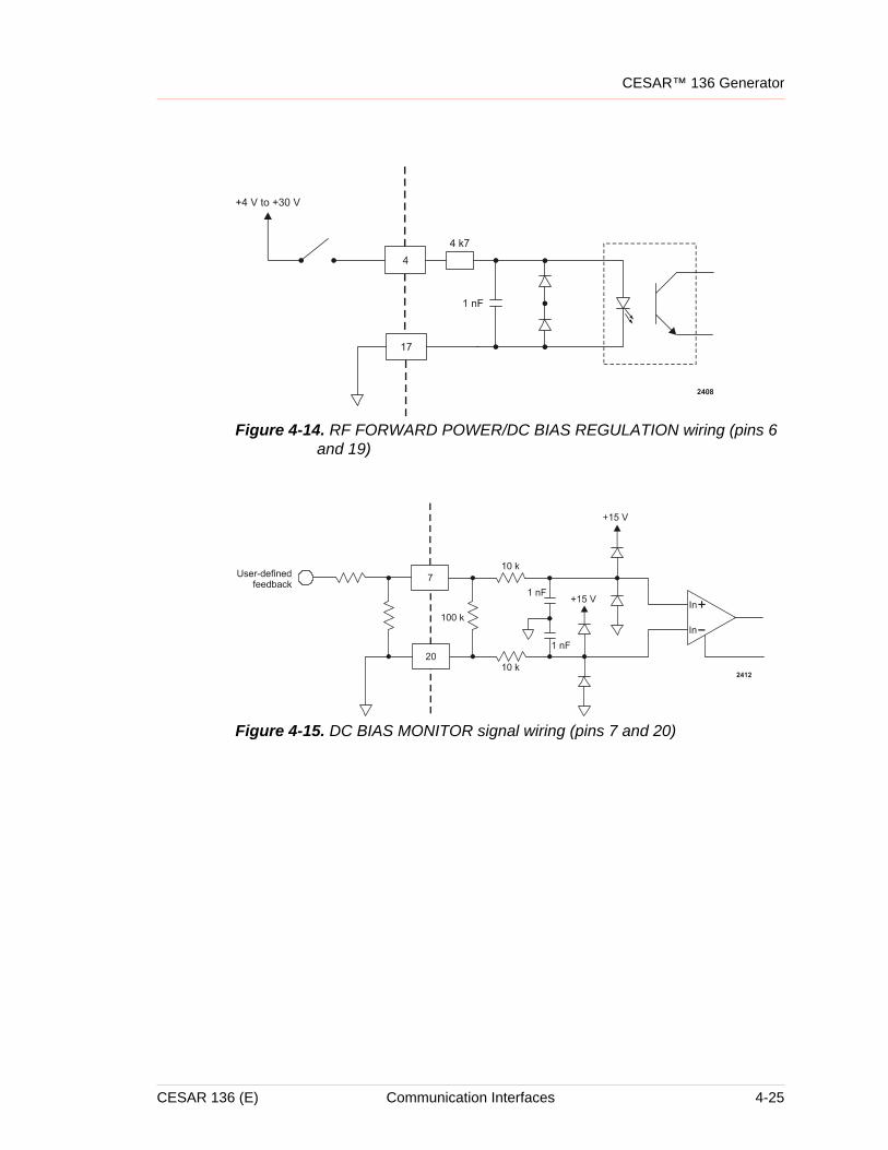
6 19 RF FORWARD POWER/DC BIAS REGULATION
Digital input
Use this signal to select DC bias or RF power regulation mode. To regulate on DC bias input, apply a positive voltage of 4 V to 30 V to this pin. To regulate on forward or load power, apply a voltage of 1.5 V or less or an open connection.
See pin 8 for switching between forward and load power regulation.
For a wiring diagram, see Figure 4-14 on page 4-25.
Table 4-2. 25-pin User Port pin descriptions (Continued)
Pin Number
Return Pin
Name Signal Type
Description
CESAR 136 (E) Communication Interfaces 4-17
Dressler® HF-Technik GmbH
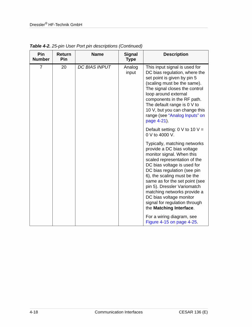
7 20 DC BIAS INPUT Analog input
This input signal is used for DC bias regulation, where the set point is given by pin 5 (scaling must be the same). The signal closes the control loop around external components in the RF path. The default range is 0 V to 10 V, but you can change this range (see “Analog Inputs” on page 4-21).
Default setting: 0 V to 10 V = 0 V to 4000 V.
Typically, matching networks provide a DC bias voltage monitor signal. When this scaled representation of the DC bias voltage is used for DC bias regulation (see pin 6), the scaling must be the same as for the set point (see pin 5). Dressler Variomatch matching networks provide a DC bias voltage monitor signal for regulation through the Matching Interface.
For a wiring diagram, see Figure 4-15 on page 4-25.
Table 4-2. 25-pin User Port pin descriptions (Continued)
Pin Number
Return Pin
Name Signal Type
Description
4-18 Communication Interfaces CESAR 136 (E)
CESAR™ 136 Generator
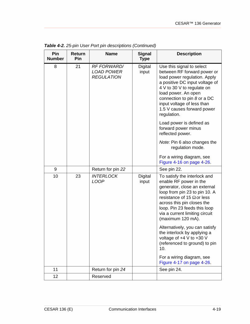
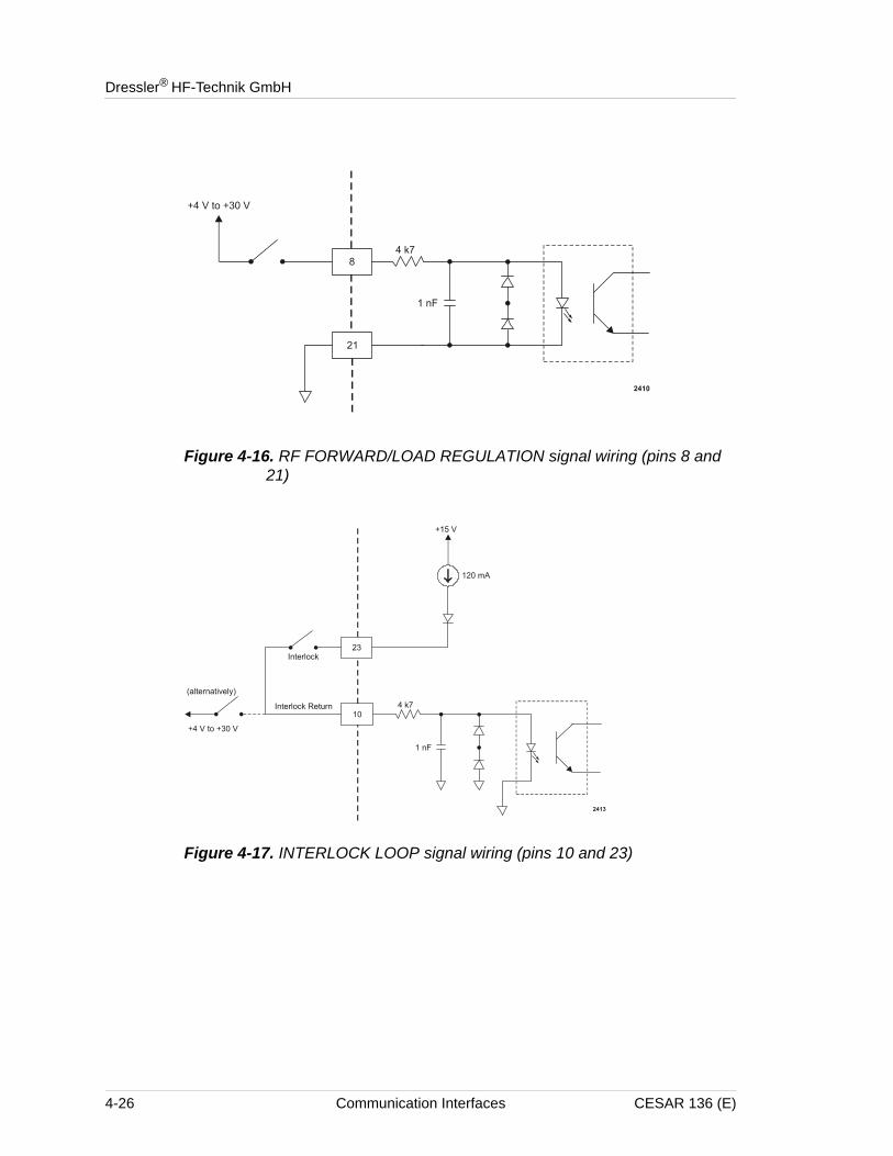
8 21 RF FORWARD/LOAD POWER REGULATION
Digital input
Use this signal to select between RF forward power or load power regulation. Apply a positive DC input voltage of 4 V to 30 V to regulate on load power. An open connection to pin 8 or a DC input voltage of less than 1.5 V causes forward power regulation.
Load power is defined as forward power minus reflected power.
Note: Pin 6 also changes the regulation mode.
For a wiring diagram, see Figure 4-16 on page 4-26.
9 Return for pin 22 See pin 22.10 23 INTERLOCK
LOOPDigital input
To satisfy the interlock and enable RF power in the generator, close an external loop from pin 23 to pin 10. A resistance of 15 Ω or less across this pin closes the loop. Pin 23 feeds this loop via a current limiting circuit (maximum 120 mA).
Alternatively, you can satisfy the interlock by applying a voltage of +4 V to +30 V (referenced to ground) to pin 10.
For a wiring diagram, see Figure 4-17 on page 4-26.
11 Return for pin 24 See pin 24.12 Reserved
Table 4-2. 25-pin User Port pin descriptions (Continued)
Pin Number
Return Pin
Name Signal Type
Description
CESAR 136 (E) Communication Interfaces 4-19
Dressler® HF-Technik GmbH
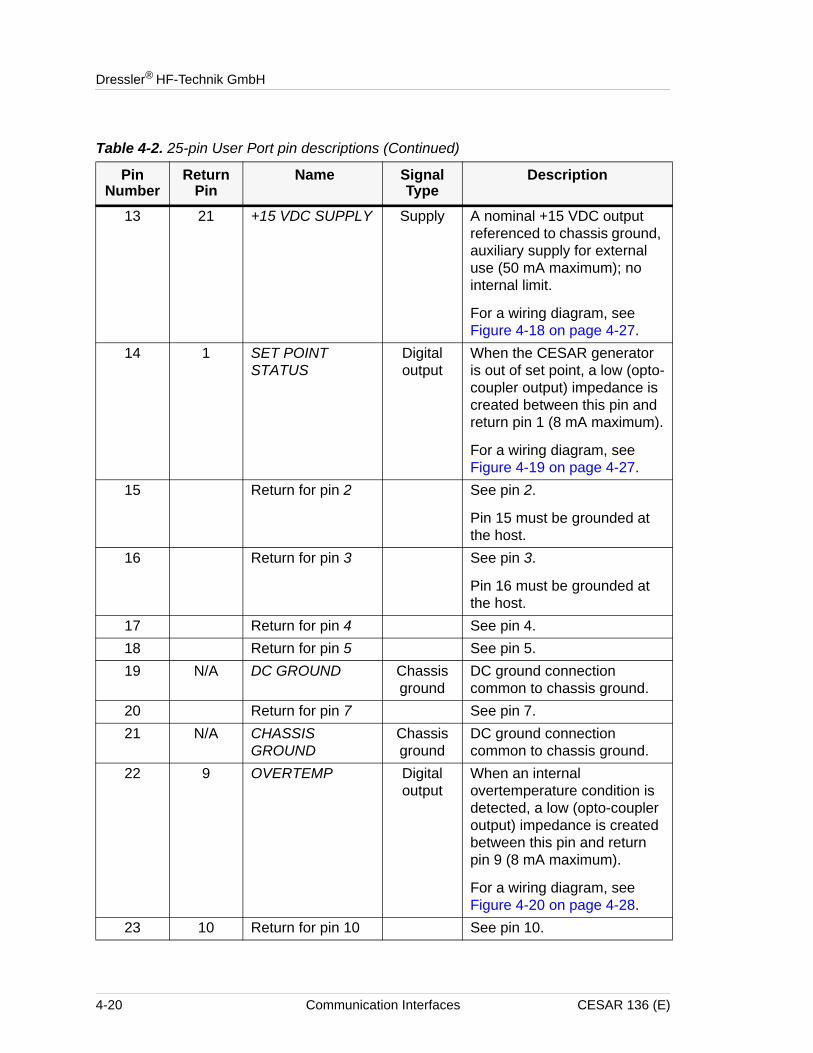
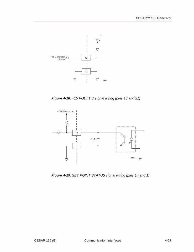
13 21 +15 VDC SUPPLY Supply A nominal +15 VDC output referenced to chassis ground, auxiliary supply for external use (50 mA maximum); no internal limit.
For a wiring diagram, see Figure 4-18 on page 4-27.
14 1 SET POINT STATUS
Digital output
When the CESAR generator is out of set point, a low (opto-coupler output) impedance is created between this pin and return pin 1 (8 mA maximum).
For a wiring diagram, see Figure 4-19 on page 4-27.
15 Return for pin 2 See pin 2.
Pin 15 must be grounded at the host.
16 Return for pin 3 See pin 3.
Pin 16 must be grounded at the host.
17 Return for pin 4 See pin 4.18 Return for pin 5 See pin 5.19 N/A DC GROUND Chassis
groundDC ground connection common to chassis ground.
20 Return for pin 7 See pin 7.21 N/A CHASSIS
GROUNDChassis ground
DC ground connection common to chassis ground.
22 9 OVERTEMP Digital output
When an internal overtemperature condition is detected, a low (opto-coupler output) impedance is created between this pin and return pin 9 (8 mA maximum).
For a wiring diagram, see Figure 4-20 on page 4-28.
23 10 Return for pin 10 See pin 10.
Table 4-2. 25-pin User Port pin descriptions (Continued)
Pin Number
Return Pin
Name Signal Type
Description
4-20 Communication Interfaces CESAR 136 (E)
CESAR™ 136 Generator
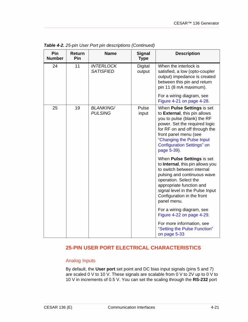
25-PIN USER PORT ELECTRICAL CHARACTERISTICS
Analog Inputs
By default, the User port set point and DC bias input signals (pins 5 and 7) are scaled 0 V to 10 V. These signals are scalable from 0 V to 2V up to 0 V to 10 V in increments of 0.5 V. You can set the scaling through the RS-232 port
24 11 INTERLOCK SATISFIED
Digital output
When the interlock is satisfied, a low (opto-coupler output) impedance is created between this pin and return pin 11 (8 mA maximum).
For a wiring diagram, see Figure 4-21 on page 4-28.
25 19 BLANKING/PULSING
Pulse input
When Pulse Settings is set to External, this pin allows you to pulse (blank) the RF power. Set the required logic for RF on and off through the front panel menu (see “Changing the Pulse Input Configuration Settings” on page 5-39).
When Pulse Settings is set to Internal, this pin allows you to switch between internal pulsing and continuous wave operation. Select the appropriate function and signal level in the Pulse Input Configuration in the front panel menu.
For a wiring diagram, see Figure 4-22 on page 4-29.
For more information, see “Setting the Pulse Function” on page 5-33
Table 4-2. 25-pin User Port pin descriptions (Continued)
Pin Number
Return Pin
Name Signal Type
Description
CESAR 136 (E) Communication Interfaces 4-21
Dressler® HF-Technik GmbH
or the PROFIBUS port (see command 30 in Table 4-16 on page 4-64) or through the front panel menu commands (see “Changing the Device Configuration Settings” on page 5-40).
Note: Using lower input voltages decreases resolution.
Analog Outputs
By default, the User port analog output signals (pins 2 and 3) are scaled 0 V to 10 V. These signals are scalable from 0 V to 2V up to 0 V to 10 V in increments of 0.5 V. You can set the scaling through the RS-232 port or the PROFIBUS port (see command 30 in Table 4-16 on page 4-64) or through the front panel menu commands (see “Changing the Device Configuration Settings” on page 5-40).
Note: Using lower output voltages decreases resolution.
These signals are driven by operational amplifiers capable of driving high-capacitance loads such as those expected in shielded interface applications. The user’s receiver must present a 10 kΩ (or higher) impedance to these signals. The readback signals represent the forward and reflected power as measured at the output of the CESAR generator.
Digital Inputs
Pins 4, 6, 8, and 10 are opto-coupled. The user’s signal drives the LED in the opto-coupler through a 4.7 kΩ resistor. A signal level of 4 V to 30 V applied to the input pin activates the signal.
Digital Outputs
The status signals provided by the generator (pins 14, 22, and 24) are opto-coupled with NPN transistor outputs. The collector and emitter of each transistor are provided to the User interface. Each transistor can provide a maximum of 8 mA of collector current and may be operated with a collector-to-emitter voltage of up to 30 V.
Pulse Input
The pulse input (pin 25) is a high-speed opto-coupled input. The user’s signal drives the LED in the opto-coupler through a 1.2 kΩ resistor. A signal level of 3 V to 12 V applied to the input pin activates the signal.
Interlock
The interlock signal (pins 10 and 23) enables the RF power generation. Pin 10 is tied to the generator’s +15 V supply. Connecting pin 10 to pin 23 closes the loop, enabling RF power.
4-22 Communication Interfaces CESAR 136 (E)
CESAR™ 136 Generator
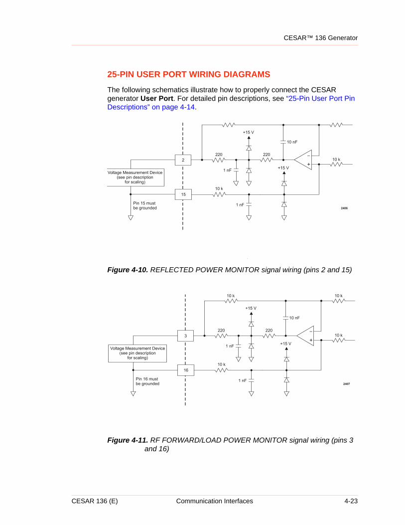
25-PIN USER PORT WIRING DIAGRAMS
The following schematics illustrate how to properly connect the CESAR generator User Port. For detailed pin descriptions, see “25-Pin User Port Pin Descriptions” on page 4-14.
Figure 4-10. REFLECTED POWER MONITOR signal wiring (pins 2 and 15)
Figure 4-11. RF FORWARD/LOAD POWER MONITOR signal wiring (pins 3 and 16)
CESAR 136 (E) Communication Interfaces 4-23
Dressler® HF-Technik GmbH
Figure 4-12. RF POWER ON signal wiring (pins 4 and 17)
Figure 4-13. SET POINT signal wiring (pins 5 and 18)
4-24 Communication Interfaces CESAR 136 (E)
CESAR™ 136 Generator
Figure 4-14. RF FORWARD POWER/DC BIAS REGULATION wiring (pins 6 and 19)
Figure 4-15. DC BIAS MONITOR signal wiring (pins 7 and 20)
CESAR 136 (E) Communication Interfaces 4-25
Dressler® HF-Technik GmbH
Figure 4-16. RF FORWARD/LOAD REGULATION signal wiring (pins 8 and 21)
Figure 4-17. INTERLOCK LOOP signal wiring (pins 10 and 23)
4-26 Communication Interfaces CESAR 136 (E)
CESAR™ 136 Generator
Figure 4-18. +15 VOLT DC signal wiring (pins 13 and 21)
Figure 4-19. SET POINT STATUS signal wiring (pins 14 and 1)
CESAR 136 (E) Communication Interfaces 4-27
Dressler® HF-Technik GmbH
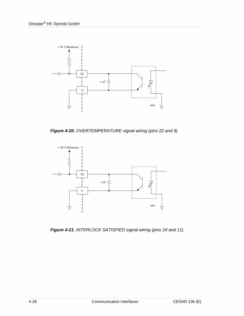
Figure 4-20. OVERTEMPERATURE signal wiring (pins 22 and 9)
Figure 4-21. INTERLOCK SATISFIED signal wiring (pins 24 and 11)
4-28 Communication Interfaces CESAR 136 (E)
CESAR™ 136 Generator
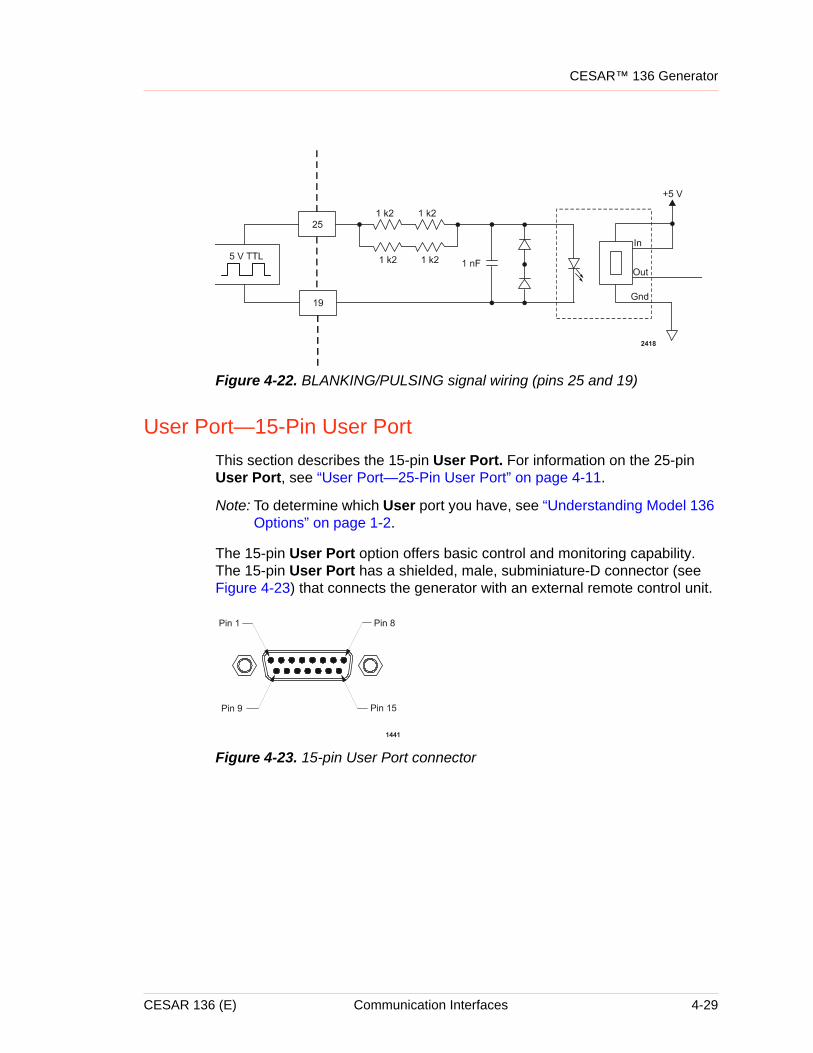
Figure 4-22. BLANKING/PULSING signal wiring (pins 25 and 19)
User Port—15-Pin User PortThis section describes the 15-pin User Port. For information on the 25-pin User Port, see “User Port—25-Pin User Port” on page 4-11.
Note: To determine which User port you have, see “Understanding Model 136 Options” on page 1-2.
The 15-pin User Port option offers basic control and monitoring capability. The 15-pin User Port has a shielded, male, subminiature-D connector (see Figure 4-23) that connects the generator with an external remote control unit.
Figure 4-23. 15-pin User Port connector
CESAR 136 (E) Communication Interfaces 4-29
Dressler® HF-Technik GmbH
SATISFYING THE INTERLOCK
Each CESAR generator with a 15-pin User Port also has an Interlock interface that allows you to integrate any CESAR generator into a system interlock loop that interrupts delivered RF power.
Even if you do not connect the CESAR generator into a larger system interlock loop, you must make the proper connections for the unit to enable RF power.
The CESAR Generator may be shipped with an interlock jumper plug that provides a connection between the interlock pins. You can use this jumper plug to satisfy the interlock and enable operation in situations where you do not intend to connect the remaining pins on this port.
Dressler® HF-Technik GmbH’s products only include interlocks and limits when required by product specification. Interlocks and limits in Dressler® HF-Technik GmbH products are not meant to meet or satisfy safety requirements. Where interlocks or limits exist, you must still meet and satisfy safety requirements. The presence of interlocks or limits does not imply operator protection.
Using the interlock jumper plug disables the interlock function.
4-30 Communication Interfaces CESAR 136 (E)
CESAR™ 136 Generator
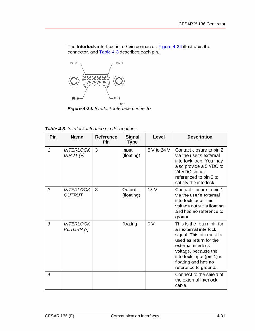
The Interlock interface is a 9-pin connector. Figure 4-24 illustrates the connector, and Table 4-3 describes each pin.
Figure 4-24. Interlock interface connector
Table 4-3. Interlock interface pin descriptions
Pin Name Reference Pin
Signal Type
Level Description
1 INTERLOCK INPUT (+)
3 Input (floating)
5 V to 24 V Contact closure to pin 2 via the user’s external interlock loop. You may also provide a 5 VDC to 24 VDC signal referenced to pin 3 to satisfy the interlock
2 INTERLOCK OUTPUT
3 Output (floating)
15 V Contact closure to pin 1 via the user’s external interlock loop. This voltage output is floating and has no reference to ground.
3 INTERLOCK RETURN (-)
floating 0 V This is the return pin for an external interlock signal. This pin must be used as return for the external interlock voltage, because the interlock input (pin 1) is floating and has no reference to ground.
4 Connect to the shield of the external interlock cable.
CESAR 136 (E) Communication Interfaces 4-31
Dressler® HF-Technik GmbH
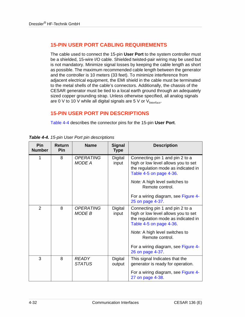
15-PIN USER PORT CABLING REQUIREMENTS
The cable used to connect the 15-pin User Port to the system controller must be a shielded, 15-wire I/O cable. Shielded twisted-pair wiring may be used but is not mandatory. Minimize signal losses by keeping the cable length as short as possible. The maximum recommended cable length between the generator and the controller is 10 meters (33 feet). To minimize interference from adjacent electrical equipment, the EMI shield in the cable must be terminated to the metal shells of the cable’s connectors. Additionally, the chassis of the CESAR generator must be tied to a local earth ground through an adequately sized copper grounding strap. Unless otherwise specified, all analog signals are 0 V to 10 V while all digital signals are 5 V or VInterface.
15-PIN USER PORT PIN DESCRIPTIONS
Table 4-4 describes the connector pins for the 15-pin User Port.
Table 4-4. 15-pin User Port pin descriptions
Pin Number
Return Pin
Name Signal Type
Description
1 8 OPERATING MODE A
Digital input
Connecting pin 1 and pin 2 to a high or low level allows you to set the regulation mode as indicated in Table 4-5 on page 4-36.
Note: A high level switches to Remote control.
For a wiring diagram, see Figure 4-25 on page 4-37.
2 8 OPERATING MODE B
Digital input
Connecting pin 1 and pin 2 to a high or low level allows you to set the regulation mode as indicated in Table 4-5 on page 4-36.
Note: A high level switches to Remote control.
For a wiring diagram, see Figure 4-26 on page 4-37.
3 8 READY STATUS
Digital output
This signal Indicates that the generator is ready for operation.
For a wiring diagram, see Figure 4-27 on page 4-38.
4-32 Communication Interfaces CESAR 136 (E)
CESAR™ 136 Generator
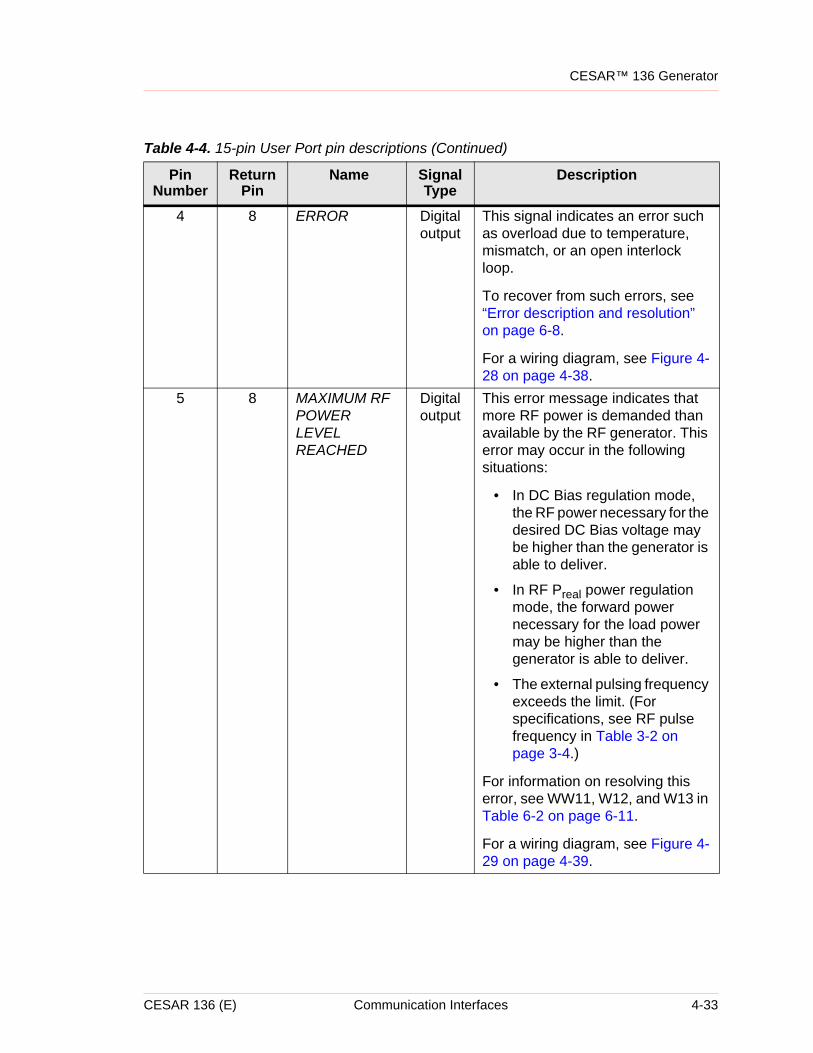
4 8 ERROR Digital output
This signal indicates an error such as overload due to temperature, mismatch, or an open interlock loop.
To recover from such errors, see “Error description and resolution” on page 6-8.
For a wiring diagram, see Figure 4-28 on page 4-38.
5 8 MAXIMUM RF POWER LEVEL REACHED
Digital output
This error message indicates that more RF power is demanded than available by the RF generator. This error may occur in the following situations:
• In DC Bias regulation mode, the RF power necessary for the desired DC Bias voltage may be higher than the generator is able to deliver.
• In RF Preal power regulation mode, the forward power necessary for the load power may be higher than the generator is able to deliver.
• The external pulsing frequency exceeds the limit. (For specifications, see RF pulse frequency in Table 3-2 on page 3-4.)
For information on resolving this error, see WW11, W12, and W13 in Table 6-2 on page 6-11.
For a wiring diagram, see Figure 4-29 on page 4-39.
Table 4-4. 15-pin User Port pin descriptions (Continued)
Pin Number
Return Pin
Name Signal Type
Description
CESAR 136 (E) Communication Interfaces 4-33
Dressler® HF-Technik GmbH
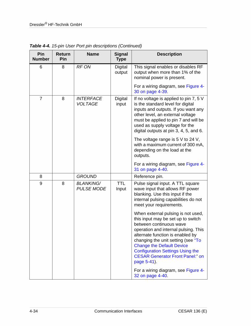
6 8 RF ON Digital output
This signal enables or disables RF output when more than 1% of the nominal power is present.
For a wiring diagram, see Figure 4-30 on page 4-39.
7 8 INTERFACE VOLTAGE
Digital input
If no voltage is applied to pin 7, 5 V is the standard level for digital inputs and outputs. If you want any other level, an external voltage must be applied to pin 7 and will be used as supply voltage for the digital outputs at pin 3, 4, 5, and 6.
The voltage range is 5 V to 24 V, with a maximum current of 300 mA, depending on the load at the outputs.
For a wiring diagram, see Figure 4-31 on page 4-40.
8 GROUND Reference pin. 9 8 BLANKING/
PULSE MODETTL Input
Pulse signal input. A TTL square wave input that allows RF power blanking. Use this input if the internal pulsing capabilities do not meet your requirements.
When external pulsing is not used, this input may be set up to switch between continuous wave operation and internal pulsing. This alternate function is enabled by changing the unit setting (see “To Change the Default Device Configuration Settings Using the CESAR Generator Front Panel:” on page 5-41).
For a wiring diagram, see Figure 4-32 on page 4-40.
Table 4-4. 15-pin User Port pin descriptions (Continued)
Pin Number
Return Pin
Name Signal Type
Description
4-34 Communication Interfaces CESAR 136 (E)
CESAR™ 136 Generator
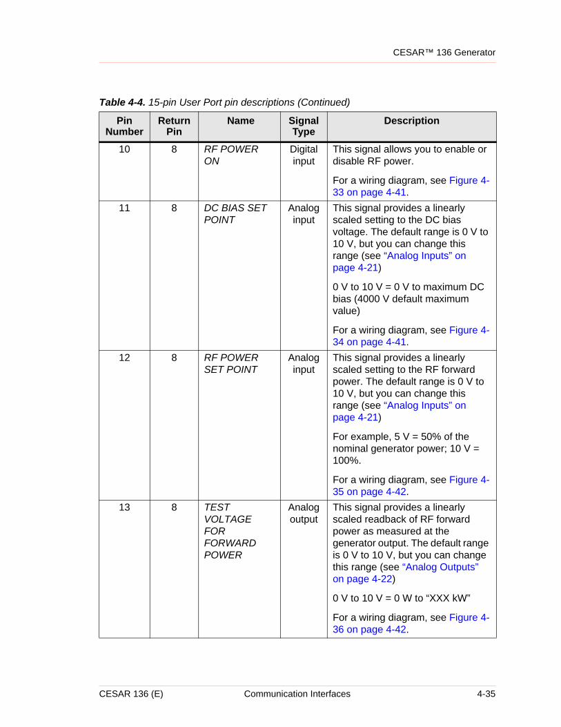
10 8 RF POWER ON
Digital input
This signal allows you to enable or disable RF power.
For a wiring diagram, see Figure 4-33 on page 4-41.
11 8 DC BIAS SET POINT
Analog input
This signal provides a linearly scaled setting to the DC bias voltage. The default range is 0 V to 10 V, but you can change this range (see “Analog Inputs” on page 4-21)
0 V to 10 V = 0 V to maximum DC bias (4000 V default maximum value)
For a wiring diagram, see Figure 4-34 on page 4-41.
12 8 RF POWER SET POINT
Analog input
This signal provides a linearly scaled setting to the RF forward power. The default range is 0 V to 10 V, but you can change this range (see “Analog Inputs” on page 4-21)
For example, 5 V = 50% of the nominal generator power; 10 V = 100%.
For a wiring diagram, see Figure 4-35 on page 4-42.
13 8 TEST VOLTAGE FOR FORWARD POWER
Analog output
This signal provides a linearly scaled readback of RF forward power as measured at the generator output. The default range is 0 V to 10 V, but you can change this range (see “Analog Outputs” on page 4-22)
0 V to 10 V = 0 W to “XXX kW”
For a wiring diagram, see Figure 4-36 on page 4-42.
Table 4-4. 15-pin User Port pin descriptions (Continued)
Pin Number
Return Pin
Name Signal Type
Description
CESAR 136 (E) Communication Interfaces 4-35
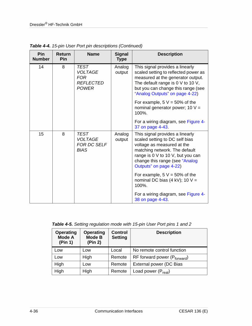
Dressler® HF-Technik GmbH
14 8 TEST VOLTAGE FOR REFLECTED POWER
Analog output
This signal provides a linearly scaled setting to reflected power as measured at the generator output. The default range is 0 V to 10 V, but you can change this range (see “Analog Outputs” on page 4-22)
For example, 5 V = 50% of the nominal generator power; 10 V = 100%.
For a wiring diagram, see Figure 4-37 on page 4-43.
15 8 TEST VOLTAGE FOR DC SELF BIAS
Analog output
This signal provides a linearly scaled setting to DC self bias voltage as measured at the matching network. The default range is 0 V to 10 V, but you can change this range (see “Analog Outputs” on page 4-22)
For example, 5 V = 50% of the nominal DC bias (4 kV); 10 V = 100%.
For a wiring diagram, see Figure 4-38 on page 4-43.
Table 4-4. 15-pin User Port pin descriptions (Continued)
Pin Number
Return Pin
Name Signal Type
Description
Table 4-5. Setting regulation mode with 15-pin User Port pins 1 and 2
Operating Mode A (Pin 1)
Operating Mode B (Pin 2)
Control Setting
Description
Low Low Local No remote control functionLow High Remote RF forward power (Pforward)High Low Remote External power (DC BiasHigh High Remote Load power (Preal)
4-36 Communication Interfaces CESAR 136 (E)
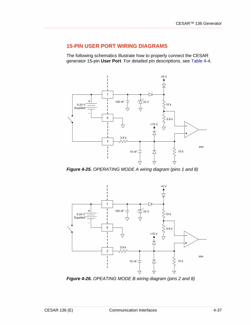
CESAR™ 136 Generator
15-PIN USER PORT WIRING DIAGRAMS
The following schematics illustrate how to properly connect the CESAR generator 15-pin User Port. For detailed pin descriptions, see Table 4-4.
Figure 4-25. OPERATING MODE A wiring diagram (pins 1 and 8)
Figure 4-26. OPEATING MODE B wiring diagram (pins 2 and 8)
CESAR 136 (E) Communication Interfaces 4-37
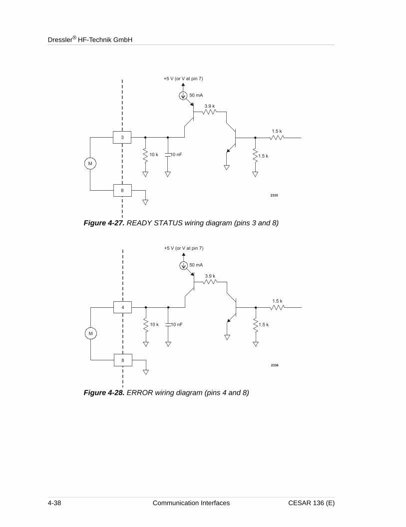
Dressler® HF-Technik GmbH
Figure 4-27. READY STATUS wiring diagram (pins 3 and 8)
Figure 4-28. ERROR wiring diagram (pins 4 and 8)
4-38 Communication Interfaces CESAR 136 (E)
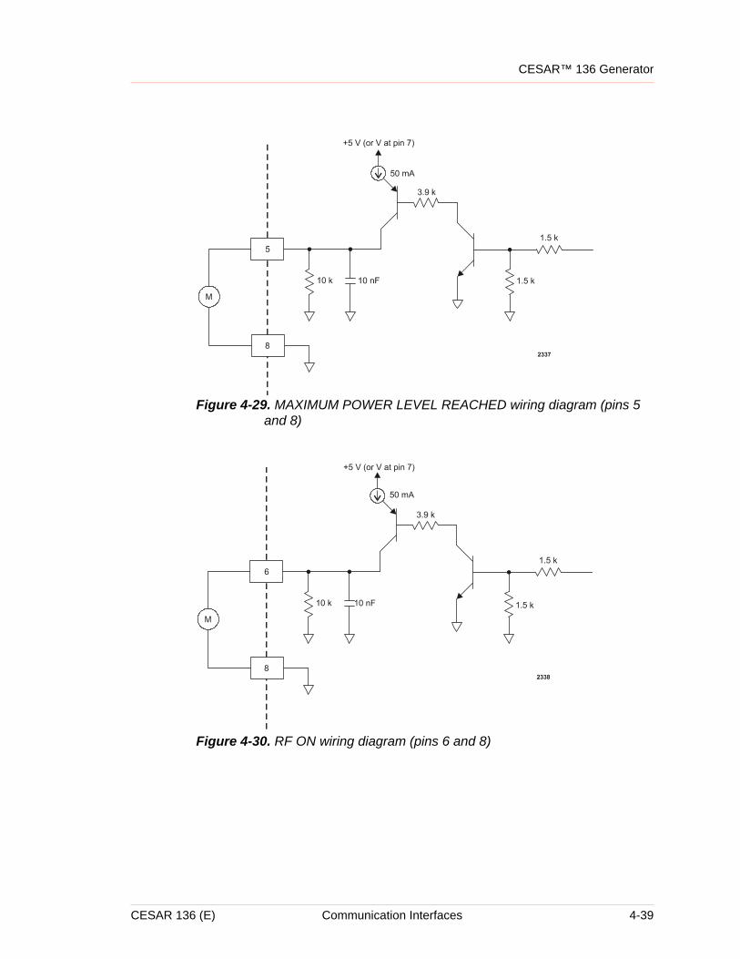
CESAR™ 136 Generator
Figure 4-29. MAXIMUM POWER LEVEL REACHED wiring diagram (pins 5 and 8)
Figure 4-30. RF ON wiring diagram (pins 6 and 8)
CESAR 136 (E) Communication Interfaces 4-39
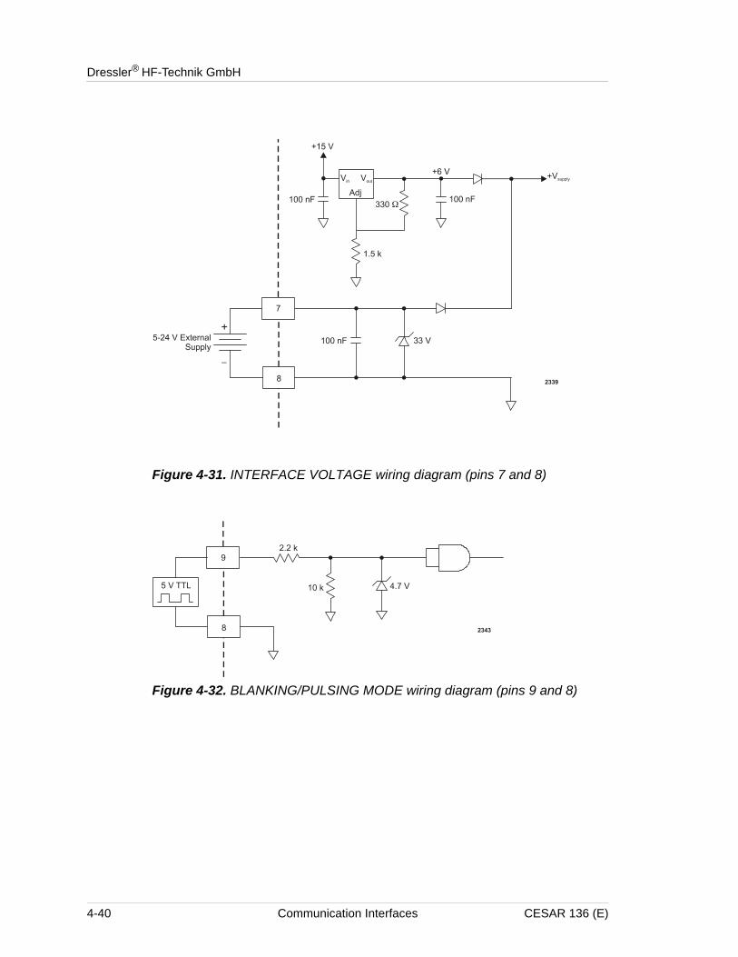
Dressler® HF-Technik GmbH
Figure 4-31. INTERFACE VOLTAGE wiring diagram (pins 7 and 8)
Figure 4-32. BLANKING/PULSING MODE wiring diagram (pins 9 and 8)
4-40 Communication Interfaces CESAR 136 (E)
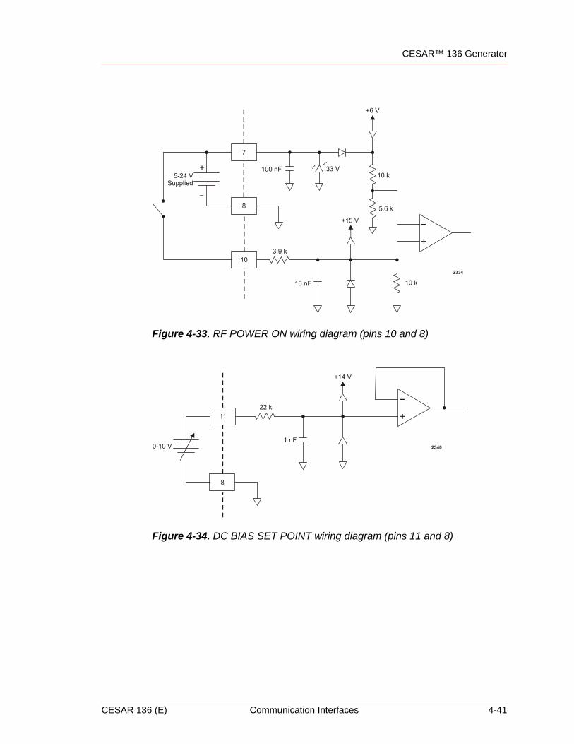
CESAR™ 136 Generator
Figure 4-33. RF POWER ON wiring diagram (pins 10 and 8)
Figure 4-34. DC BIAS SET POINT wiring diagram (pins 11 and 8)
CESAR 136 (E) Communication Interfaces 4-41
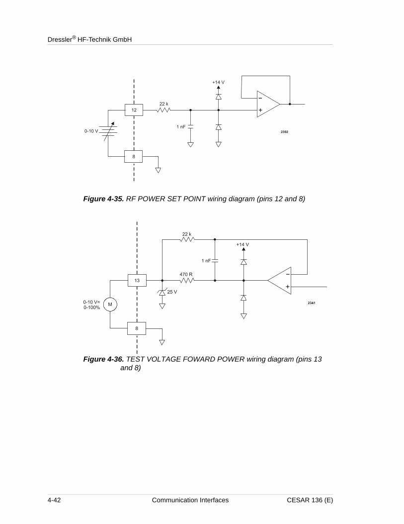
Dressler® HF-Technik GmbH
Figure 4-35. RF POWER SET POINT wiring diagram (pins 12 and 8)
Figure 4-36. TEST VOLTAGE FOWARD POWER wiring diagram (pins 13 and 8)
4-42 Communication Interfaces CESAR 136 (E)
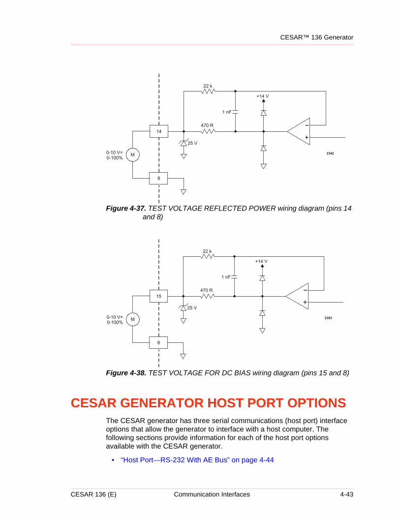
CESAR™ 136 Generator
Figure 4-37. TEST VOLTAGE REFLECTED POWER wiring diagram (pins 14 and 8)
Figure 4-38. TEST VOLTAGE FOR DC BIAS wiring diagram (pins 15 and 8)
CESAR GENERATOR HOST PORT OPTIONSThe CESAR generator has three serial communications (host port) interface options that allow the generator to interface with a host computer. The following sections provide information for each of the host port options available with the CESAR generator.
• “Host Port—RS-232 With AE Bus” on page 4-44
CESAR 136 (E) Communication Interfaces 4-43
Dressler® HF-Technik GmbH
• “Host Port—PROFIBUS” on page 4-51
• “Host Port—Ethernet (Modbus/TCP)” on page 4-57
Note: To determine which host port option you have, see “Understanding Model 136 Options” on page 1-2.
The host port commands are very similar for all interfaces. All host port commands are listed and described in “Host Port Commands” on page 4-62.
Host Port—RS-232 With AE BusThis section describes the RS-232 host port. For information on the PROFIBUS host port, see “Host Port—PROFIBUS” on page 4-51. For information on the Ethernet host port, see “Host Port—Ethernet (Modbus/TCP)” on page 4-57.
Note: To determine which option you have, see “Understanding Model 136 Options” on page 1-2.
The RS-232 AE Bus host port interface uses an RS-232 signal format and AE Bus communication protocol. Refer to “AE Bus Protocol” for details on the communications protocol.
For a complete list of available functions, see “Host Port Commands” on page 4-62.
4-44 Communication Interfaces CESAR 136 (E)
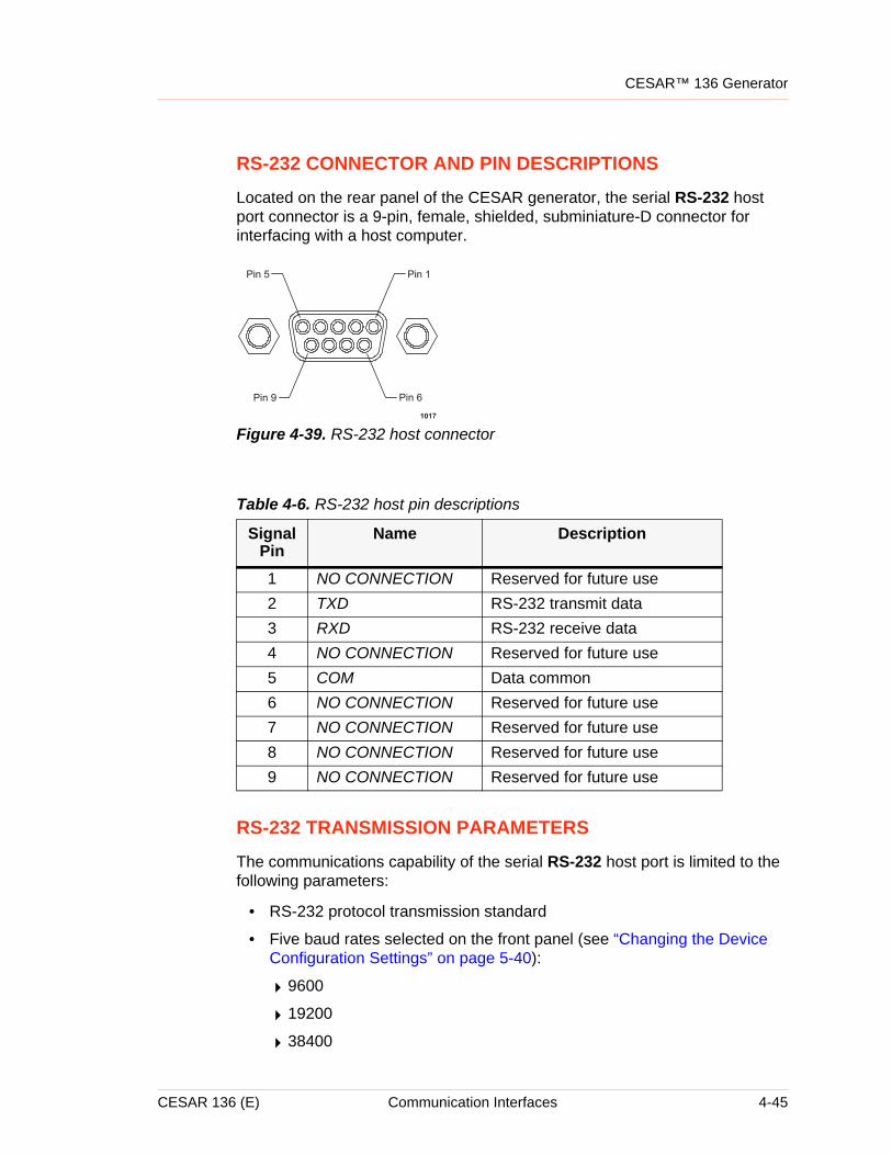
CESAR™ 136 Generator
RS-232 CONNECTOR AND PIN DESCRIPTIONS
Located on the rear panel of the CESAR generator, the serial RS-232 host port connector is a 9-pin, female, shielded, subminiature-D connector for interfacing with a host computer.
Figure 4-39. RS-232 host connector
RS-232 TRANSMISSION PARAMETERS
The communications capability of the serial RS-232 host port is limited to the following parameters:
• RS-232 protocol transmission standard
• Five baud rates selected on the front panel (see “Changing the Device Configuration Settings” on page 5-40):
49600
419200
438400
Table 4-6. RS-232 host pin descriptions
Signal Pin
Name Description
1 NO CONNECTION Reserved for future use2 TXD RS-232 transmit data3 RXD RS-232 receive data4 NO CONNECTION Reserved for future use5 COM Data common6 NO CONNECTION Reserved for future use7 NO CONNECTION Reserved for future use8 NO CONNECTION Reserved for future use9 NO CONNECTION Reserved for future use
CESAR 136 (E) Communication Interfaces 4-45
Dressler® HF-Technik GmbH
457600
4115200
• Odd parity
• One start bit, eight data bits, one stop bit
• Low-order bytes are transmitted before high-order bytes.
The host computer must finish one transaction with the CESAR generator before it initiates another one, either with the same unit or any other unit.
Note: The CESAR generator sends data through pin 2 (TXD.D). This pin must be connected to the receive pin (RXD.D) on the host computer’s serial connector. The receive pin is normally pin 2 for a standard, 9-pin serial port and normally pin 3 for a standard, 25-pin serial port.
AE BUS PROTOCOL
The AE Bus protocol uses pure binary data (nothing is coded in ASCII) and is designed to facilitate direct communications between a host computer and the CESAR generator.
The AE Bus message packet combines a set quantity of bits and bytes in such a way that groups of information can be sent over communications lines at one time. Five types of information (fields) make up communications message packets (see Figure 4-40):
• Header (address and the length of Data field)
• Command Number (commands are listed in Table 4-16 on page 4-64)
• Optional Length byte
• Data
• Checksum
4-46 Communication Interfaces CESAR 136 (E)
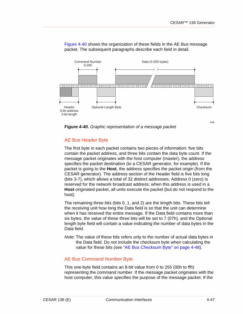
CESAR™ 136 Generator
Figure 4-40 shows the organization of these fields in the AE Bus message packet. The subsequent paragraphs describe each field in detail.
Figure 4-40. Graphic representation of a message packet
AE Bus Header Byte
The first byte in each packet contains two pieces of information: five bits contain the packet address, and three bits contain the data byte count. If the message packet originates with the host computer (master), the address specifies the packet destination (to a CESAR generator, for example). If the packet is going to the Host, the address specifies the packet origin (from the CESAR generator). The address section of the Header field is five bits long (bits 3-7), which allows a total of 32 distinct addresses. Address 0 (zero) is reserved for the network broadcast address; when this address is used in a Host-originated packet, all units execute the packet (but do not respond to the host).
The remaining three bits (bits 0, 1, and 2) are the length bits. These bits tell the receiving unit how long the Data field is so that the unit can determine when it has received the entire message. If the Data field contains more than six bytes, the value of these three bits will be set to 7 (07h), and the Optional length byte field will contain a value indicating the number of data bytes in the Data field.
Note: The value of these bits refers only to the number of actual data bytes in the Data field. Do not include the checksum byte when calculating the value for these bits (see “AE Bus Checksum Byte” on page 4-48).
AE Bus Command Number Byte
This one-byte field contains an 8-bit value from 0 to 255 (00h to ffh) representing the command number. If the message packet originates with the host computer, this value specifies the purpose of the message packet. If the
CESAR 136 (E) Communication Interfaces 4-47
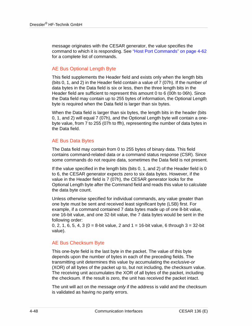
Dressler® HF-Technik GmbH
message originates with the CESAR generator, the value specifies the command to which it is responding. See “Host Port Commands” on page 4-62 for a complete list of commands.
AE Bus Optional Length Byte
This field supplements the Header field and exists only when the length bits (bits 0, 1, and 2) in the Header field contain a value of 7 (07h). If the number of data bytes in the Data field is six or less, then the three length bits in the Header field are sufficient to represent this amount 0 to 6 (00h to 06h). Since the Data field may contain up to 255 bytes of information, the Optional Length byte is required when the Data field is larger than six bytes.
When the Data field is larger than six bytes, the length bits in the header (bits 0, 1, and 2) will equal 7 (07h), and the Optional Length byte will contain a one-byte value, from 7 to 255 (07h to ffh), representing the number of data bytes in the Data field.
AE Bus Data Bytes
The Data field may contain from 0 to 255 bytes of binary data. This field contains command-related data or a command status response (CSR). Since some commands do not require data, sometimes the Data field is not present.
If the value specified in the length bits (bits 0, 1, and 2) of the Header field is 0 to 6, the CESAR generator expects zero to six data bytes. However, if the value in the Header field is 7 (07h), the CESAR generator looks for the Optional Length byte after the Command field and reads this value to calculate the data byte count.
Unless otherwise specified for individual commands, any value greater than one byte must be sent and received least significant byte (LSB) first. For example, if a command contained 7 data bytes made up of one 8-bit value, one 16-bit value, and one 32-bit value, the 7 data bytes would be sent in the following order:0, 2, 1, 6, 5, 4, 3 (0 = 8-bit value, 2 and 1 = 16-bit value, 6 through 3 = 32-bit value).
AE Bus Checksum Byte
This one-byte field is the last byte in the packet. The value of this byte depends upon the number of bytes in each of the preceding fields. The transmitting unit determines this value by accumulating the exclusive-or (XOR) of all bytes of the packet up to, but not including, the checksum value. The receiving unit accumulates the XOR of all bytes of the packet, including the checksum. If the result is zero, the unit has received the packet intact.
The unit will act on the message only if the address is valid and the checksum is validated as having no parity errors.
4-48 Communication Interfaces CESAR 136 (E)
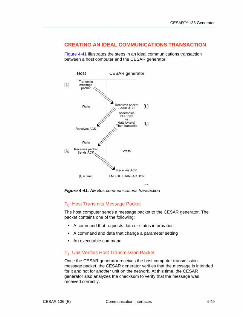
CESAR™ 136 Generator
CREATING AN IDEAL COMMUNICATIONS TRANSACTION
Figure 4-41 illustrates the steps in an ideal communications transaction between a host computer and the CESAR generator.
Figure 4-41. AE Bus communications transaction
T0: Host Transmits Message Packet
The host computer sends a message packet to the CESAR generator. The packet contains one of the following:
• A command that requests data or status information
• A command and data that change a parameter setting
• An executable command
T1: Unit Verifies Host Transmission Packet
Once the CESAR generator receives the host computer transmission message packet, the CESAR generator verifies that the message is intended for it and not for another unit on the network. At this time, the CESAR generator also analyzes the checksum to verify that the message was received correctly.
Host CESAR generator
CESAR 136 (E) Communication Interfaces 4-49
Dressler® HF-Technik GmbH
• If the address does not match, the CESAR generator does not respond to the host computer; the CESAR generator resets and resumes waiting for a message addressed to it. If the address matches but the exclusive-or (XOR) sum of the bytes in the packet (including the checksum) is not zero, the CESAR generator sends a negative acknowledgment (NAK), hexadecimal 15h, to the host computer.
• If the address matches and the message is intact, the CESAR generator sends an acknowledgment (ACK), hexadecimal 06h, to the host computer.
If the CESAR generator receives a request for data or status information, it gathers and sends the requested information. Otherwise, it evaluates the incoming command and sends a message packet that contains a one-byte data value (CSR code) to the Host (see “Host Port Command Status Response (CSR) Codes” on page 4-63). CSR code 0 is sent when the command has been accepted.
If the Host receives a NAK (15h) from the CESAR generator, the Host either retransmits the packet or does whatever else it has been programmed to do in this situation. If the Host receives an ACK (06h), it waits for the requested data or status information, or it waits for the CSR code telling it whether or not the new parameter was accepted. If the Host receives no response within a reasonable period, it takes whatever action it has been programmed to take.
T2: Unit Transmits Response to Host
The CESAR generator prepares a response packet with the requested information or appropriate CSR code, which it then transmits to the host computer. The host computer then determines, by means of the checksum, if the response packet is complete. If the host computer detects an error in the transmission (the checksum is not validated), it can request the packet be sent again by transmitting a NAK (15h).
T3: Host Acknowledges Unit Response
If the CESAR generator receives an ACK (15h) from the host computer, it returns to the normal waiting state. If the CESAR generator receives a NAK (06h) from the host computer, the CESAR generator retransmits the response packet. The CESAR generator continues to retransmit in response to NAK transmissions until the host computer stops the cycle. If the CESAR generator receives no response, it assumes an ACK and returns to the waiting state.
4-50 Communication Interfaces CESAR 136 (E)
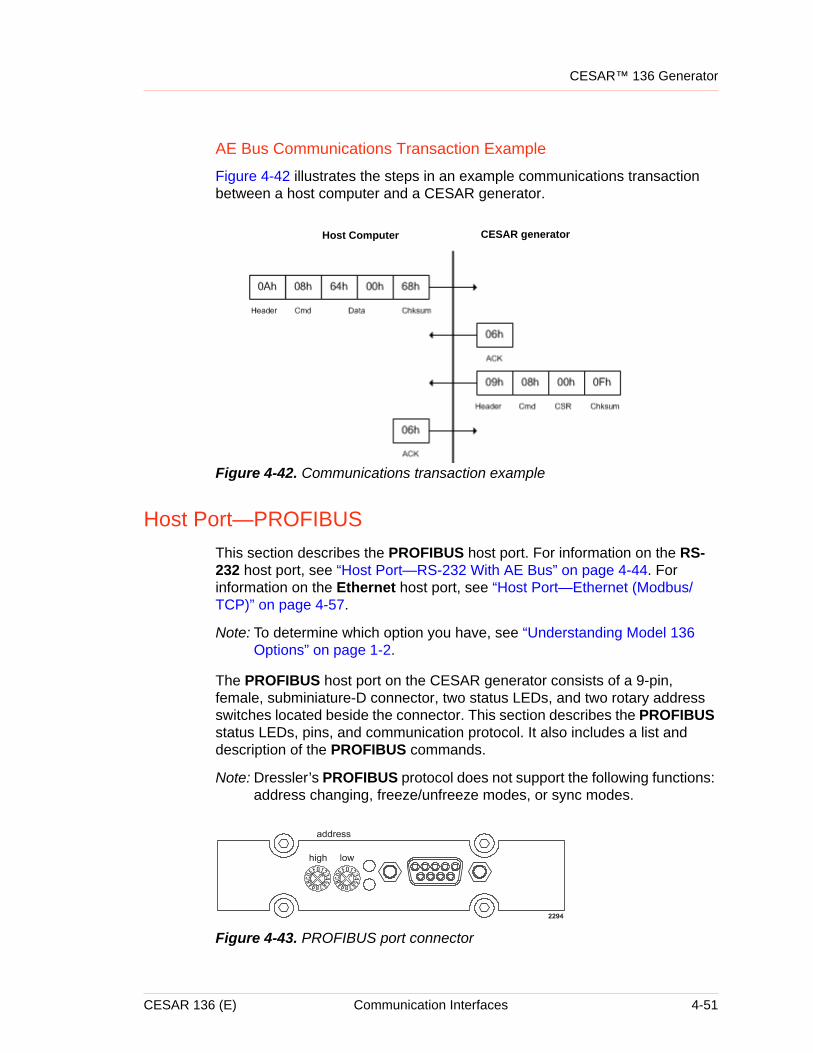
CESAR™ 136 Generator
AE Bus Communications Transaction Example
Figure 4-42 illustrates the steps in an example communications transaction between a host computer and a CESAR generator.
Figure 4-42. Communications transaction example
Host Port—PROFIBUSThis section describes the PROFIBUS host port. For information on the RS-232 host port, see “Host Port—RS-232 With AE Bus” on page 4-44. For information on the Ethernet host port, see “Host Port—Ethernet (Modbus/TCP)” on page 4-57.
Note: To determine which option you have, see “Understanding Model 136 Options” on page 1-2.
The PROFIBUS host port on the CESAR generator consists of a 9-pin, female, subminiature-D connector, two status LEDs, and two rotary address switches located beside the connector. This section describes the PROFIBUS status LEDs, pins, and communication protocol. It also includes a list and description of the PROFIBUS commands.
Note: Dressler’s PROFIBUS protocol does not support the following functions: address changing, freeze/unfreeze modes, or sync modes.
Figure 4-43. PROFIBUS port connector
Host Computer CESAR generator
CESAR 136 (E) Communication Interfaces 4-51
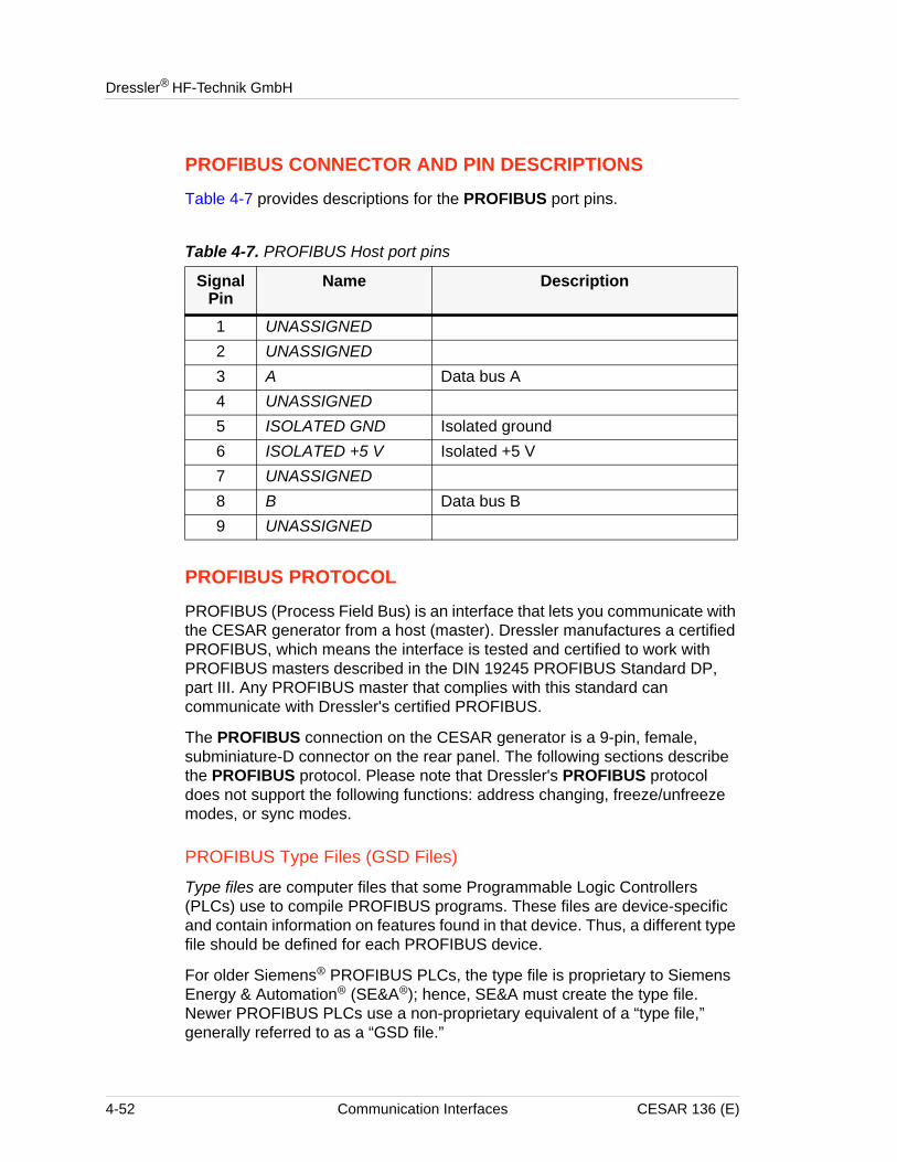
Dressler® HF-Technik GmbH
PROFIBUS CONNECTOR AND PIN DESCRIPTIONS
Table 4-7 provides descriptions for the PROFIBUS port pins.
PROFIBUS PROTOCOL
PROFIBUS (Process Field Bus) is an interface that lets you communicate with the CESAR generator from a host (master). Dressler manufactures a certified PROFIBUS, which means the interface is tested and certified to work with PROFIBUS masters described in the DIN 19245 PROFIBUS Standard DP, part III. Any PROFIBUS master that complies with this standard can communicate with Dressler's certified PROFIBUS.
The PROFIBUS connection on the CESAR generator is a 9-pin, female, subminiature-D connector on the rear panel. The following sections describe the PROFIBUS protocol. Please note that Dressler's PROFIBUS protocol does not support the following functions: address changing, freeze/unfreeze modes, or sync modes.
PROFIBUS Type Files (GSD Files)
Type files are computer files that some Programmable Logic Controllers (PLCs) use to compile PROFIBUS programs. These files are device-specific and contain information on features found in that device. Thus, a different type file should be defined for each PROFIBUS device.
For older Siemens® PROFIBUS PLCs, the type file is proprietary to Siemens Energy & Automation® (SE&A®); hence, SE&A must create the type file. Newer PROFIBUS PLCs use a non-proprietary equivalent of a “type file,” generally referred to as a “GSD file.”
Table 4-7. PROFIBUS Host port pins
Signal Pin
Name Description
1 UNASSIGNED2 UNASSIGNED3 A Data bus A4 UNASSIGNED5 ISOLATED GND Isolated ground6 ISOLATED +5 V Isolated +5 V7 UNASSIGNED8 B Data bus B9 UNASSIGNED
4-52 Communication Interfaces CESAR 136 (E)
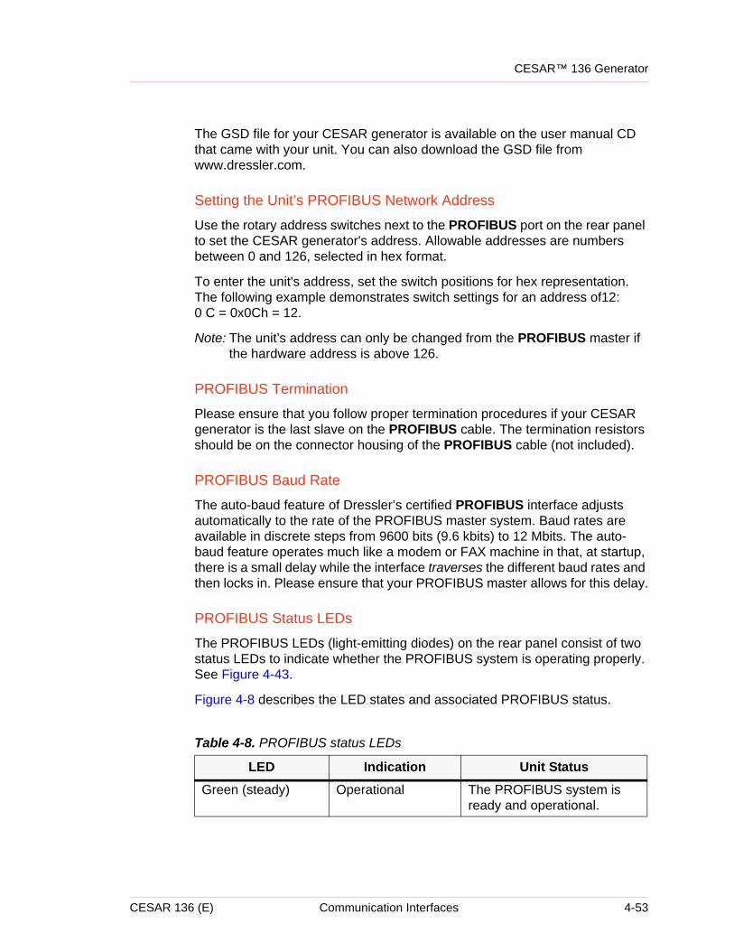
CESAR™ 136 Generator
The GSD file for your CESAR generator is available on the user manual CD that came with your unit. You can also download the GSD file from www.dressler.com.
Setting the Unit’s PROFIBUS Network Address
Use the rotary address switches next to the PROFIBUS port on the rear panel to set the CESAR generator's address. Allowable addresses are numbers between 0 and 126, selected in hex format.
To enter the unit's address, set the switch positions for hex representation. The following example demonstrates switch settings for an address of12: 0 C = 0x0Ch = 12.
Note: The unit’s address can only be changed from the PROFIBUS master if the hardware address is above 126.
PROFIBUS Termination
Please ensure that you follow proper termination procedures if your CESAR generator is the last slave on the PROFIBUS cable. The termination resistors should be on the connector housing of the PROFIBUS cable (not included).
PROFIBUS Baud Rate
The auto-baud feature of Dressler’s certified PROFIBUS interface adjusts automatically to the rate of the PROFIBUS master system. Baud rates are available in discrete steps from 9600 bits (9.6 kbits) to 12 Mbits. The auto-baud feature operates much like a modem or FAX machine in that, at startup, there is a small delay while the interface traverses the different baud rates and then locks in. Please ensure that your PROFIBUS master allows for this delay.
PROFIBUS Status LEDs
The PROFIBUS LEDs (light-emitting diodes) on the rear panel consist of two status LEDs to indicate whether the PROFIBUS system is operating properly. See Figure 4-43.
Figure 4-8 describes the LED states and associated PROFIBUS status.
Table 4-8. PROFIBUS status LEDs
LED Indication Unit StatusGreen (steady) Operational The PROFIBUS system is
ready and operational.
CESAR 136 (E) Communication Interfaces 4-53
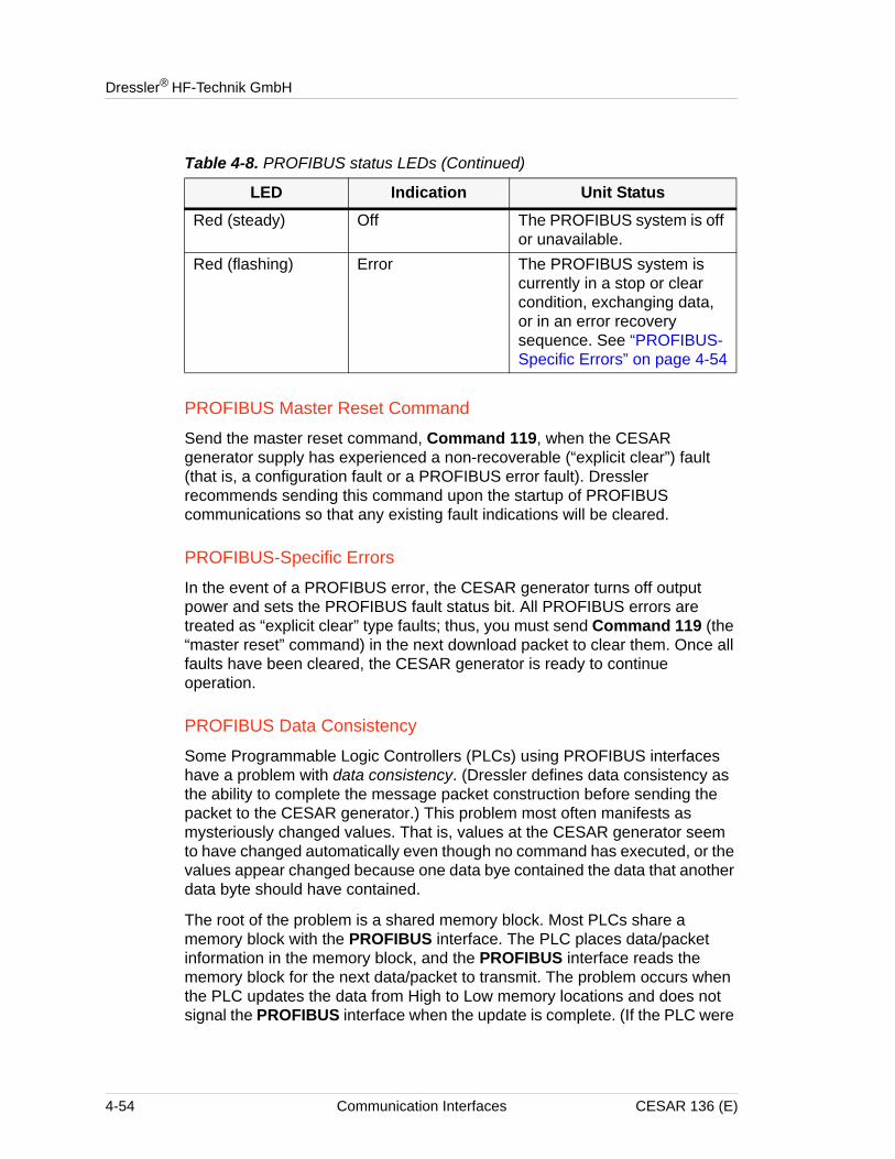
Dressler® HF-Technik GmbH
PROFIBUS Master Reset Command
Send the master reset command, Command 119, when the CESAR generator supply has experienced a non-recoverable (“explicit clear”) fault (that is, a configuration fault or a PROFIBUS error fault). Dressler recommends sending this command upon the startup of PROFIBUS communications so that any existing fault indications will be cleared.
PROFIBUS-Specific Errors
In the event of a PROFIBUS error, the CESAR generator turns off output power and sets the PROFIBUS fault status bit. All PROFIBUS errors are treated as “explicit clear” type faults; thus, you must send Command 119 (the “master reset” command) in the next download packet to clear them. Once all faults have been cleared, the CESAR generator is ready to continue operation.
PROFIBUS Data Consistency
Some Programmable Logic Controllers (PLCs) using PROFIBUS interfaces have a problem with data consistency. (Dressler defines data consistency as the ability to complete the message packet construction before sending the packet to the CESAR generator.) This problem most often manifests as mysteriously changed values. That is, values at the CESAR generator seem to have changed automatically even though no command has executed, or the values appear changed because one data bye contained the data that another data byte should have contained.
The root of the problem is a shared memory block. Most PLCs share a memory block with the PROFIBUS interface. The PLC places data/packet information in the memory block, and the PROFIBUS interface reads the memory block for the next data/packet to transmit. The problem occurs when the PLC updates the data from High to Low memory locations and does not signal the PROFIBUS interface when the update is complete. (If the PLC were
Red (steady) Off The PROFIBUS system is off or unavailable.
Red (flashing) Error The PROFIBUS system is currently in a stop or clear condition, exchanging data, or in an error recovery sequence. See “PROFIBUS-Specific Errors” on page 4-54
Table 4-8. PROFIBUS status LEDs (Continued)
LED Indication Unit Status
4-54 Communication Interfaces CESAR 136 (E)
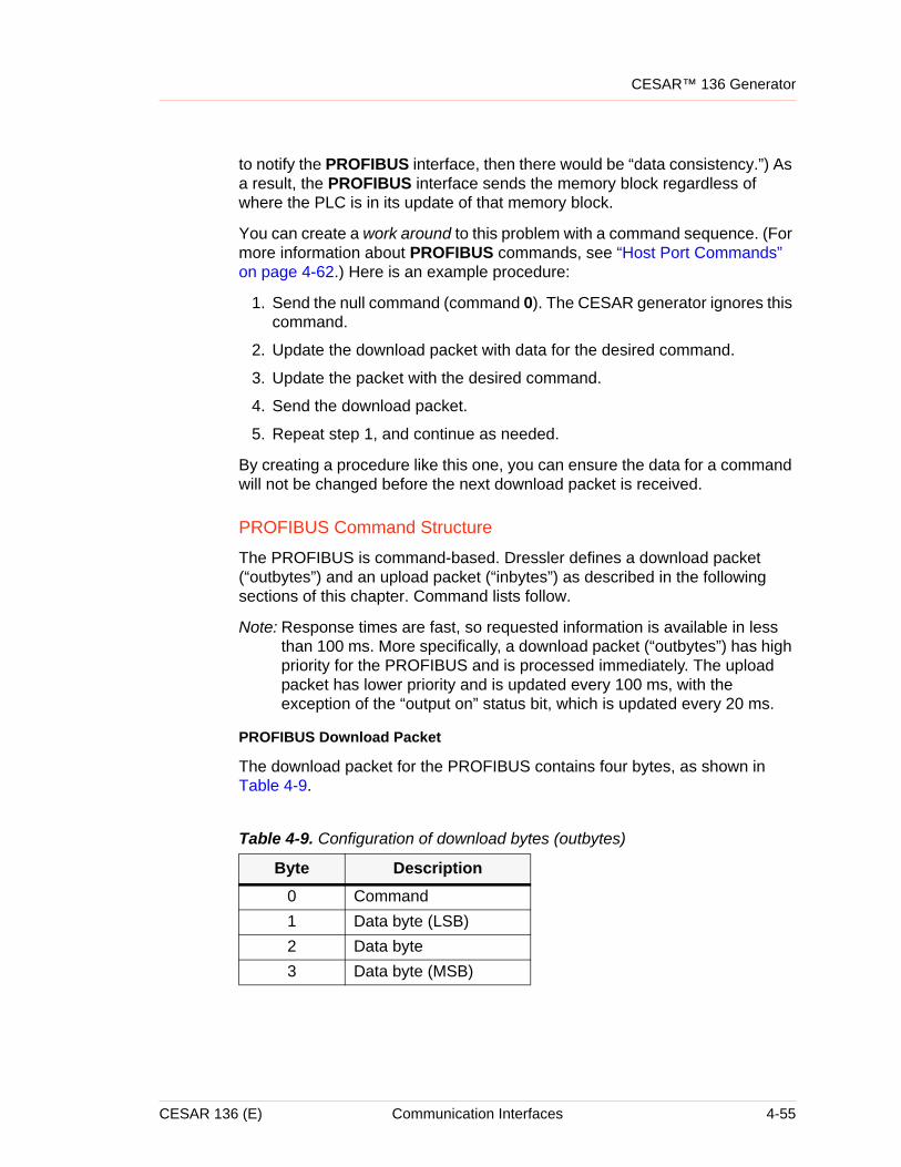
CESAR™ 136 Generator
to notify the PROFIBUS interface, then there would be “data consistency.”) As a result, the PROFIBUS interface sends the memory block regardless of where the PLC is in its update of that memory block.
You can create a work around to this problem with a command sequence. (For more information about PROFIBUS commands, see “Host Port Commands” on page 4-62.) Here is an example procedure:
1. Send the null command (command 0). The CESAR generator ignores this command.
2. Update the download packet with data for the desired command.
3. Update the packet with the desired command.
4. Send the download packet.
5. Repeat step 1, and continue as needed.
By creating a procedure like this one, you can ensure the data for a command will not be changed before the next download packet is received.
PROFIBUS Command Structure
The PROFIBUS is command-based. Dressler defines a download packet (“outbytes”) and an upload packet (“inbytes”) as described in the following sections of this chapter. Command lists follow.
Note: Response times are fast, so requested information is available in less than 100 ms. More specifically, a download packet (“outbytes”) has high priority for the PROFIBUS and is processed immediately. The upload packet has lower priority and is updated every 100 ms, with the exception of the “output on” status bit, which is updated every 20 ms.
PROFIBUS Download Packet
The download packet for the PROFIBUS contains four bytes, as shown in Table 4-9.
Table 4-9. Configuration of download bytes (outbytes)
Byte Description0 Command1 Data byte (LSB)2 Data byte3 Data byte (MSB)
CESAR 136 (E) Communication Interfaces 4-55
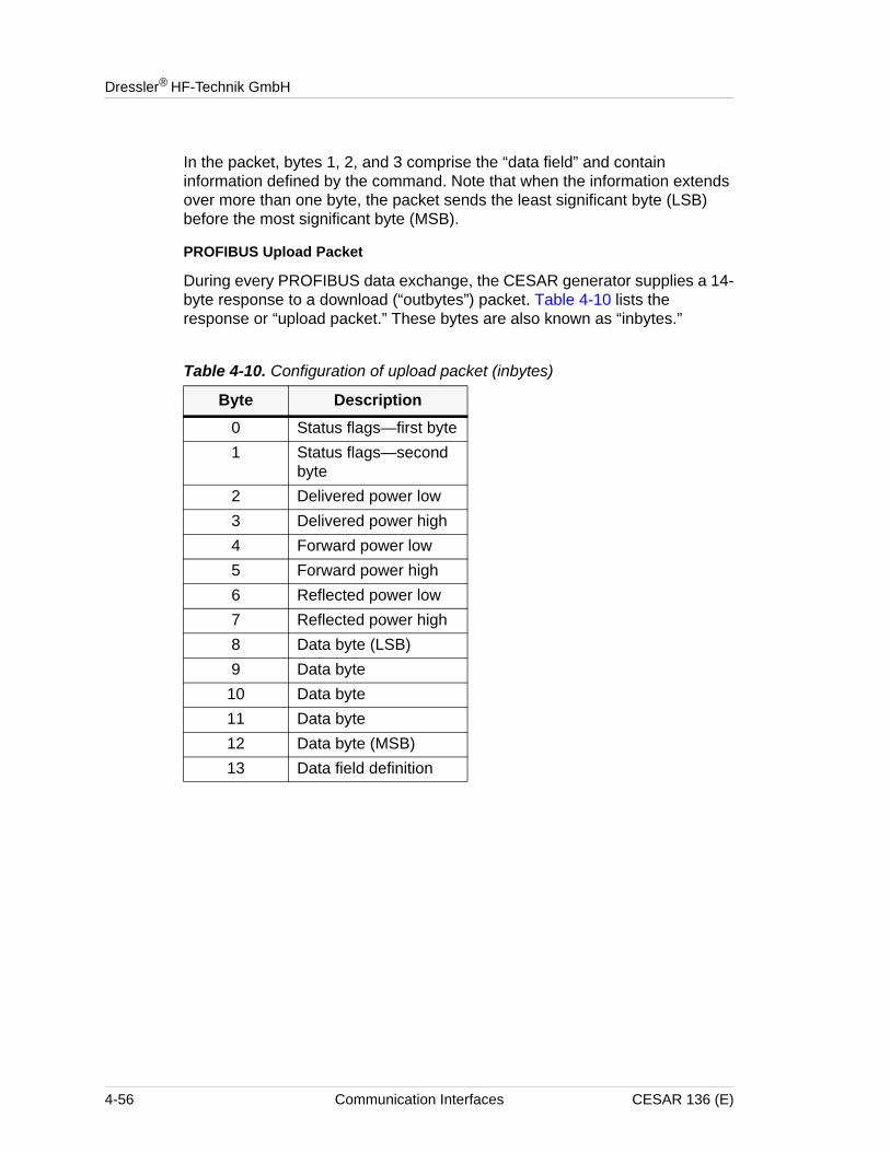
Dressler® HF-Technik GmbH
In the packet, bytes 1, 2, and 3 comprise the “data field” and contain information defined by the command. Note that when the information extends over more than one byte, the packet sends the least significant byte (LSB) before the most significant byte (MSB).
PROFIBUS Upload Packet
During every PROFIBUS data exchange, the CESAR generator supplies a 14-byte response to a download (“outbytes”) packet. Table 4-10 lists the response or “upload packet.” These bytes are also known as “inbytes.”
Table 4-10. Configuration of upload packet (inbytes)
Byte Description0 Status flags—first byte1 Status flags—second
byte2 Delivered power low3 Delivered power high4 Forward power low5 Forward power high6 Reflected power low7 Reflected power high8 Data byte (LSB)9 Data byte
10 Data byte11 Data byte12 Data byte (MSB)13 Data field definition
4-56 Communication Interfaces CESAR 136 (E)
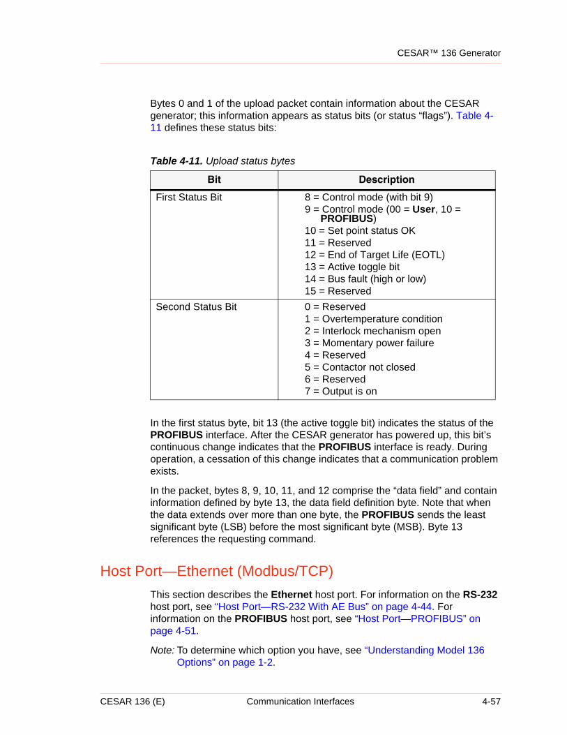
CESAR™ 136 Generator
Bytes 0 and 1 of the upload packet contain information about the CESAR generator; this information appears as status bits (or status “flags”). Table 4-11 defines these status bits:
In the first status byte, bit 13 (the active toggle bit) indicates the status of the PROFIBUS interface. After the CESAR generator has powered up, this bit’s continuous change indicates that the PROFIBUS interface is ready. During operation, a cessation of this change indicates that a communication problem exists.
In the packet, bytes 8, 9, 10, 11, and 12 comprise the “data field” and contain information defined by byte 13, the data field definition byte. Note that when the data extends over more than one byte, the PROFIBUS sends the least significant byte (LSB) before the most significant byte (MSB). Byte 13 references the requesting command.
Host Port—Ethernet (Modbus/TCP)This section describes the Ethernet host port. For information on the RS-232 host port, see “Host Port—RS-232 With AE Bus” on page 4-44. For information on the PROFIBUS host port, see “Host Port—PROFIBUS” on page 4-51.
Note: To determine which option you have, see “Understanding Model 136 Options” on page 1-2.
Table 4-11. Upload status bytes
Bit Description
First Status Bit 8 = Control mode (with bit 9)9 = Control mode (00 = User, 10 =
PROFIBUS)10 = Set point status OK11 = Reserved12 = End of Target Life (EOTL)13 = Active toggle bit14 = Bus fault (high or low)15 = Reserved
Second Status Bit 0 = Reserved1 = Overtemperature condition2 = Interlock mechanism open3 = Momentary power failure4 = Reserved5 = Contactor not closed6 = Reserved7 = Output is on
CESAR 136 (E) Communication Interfaces 4-57
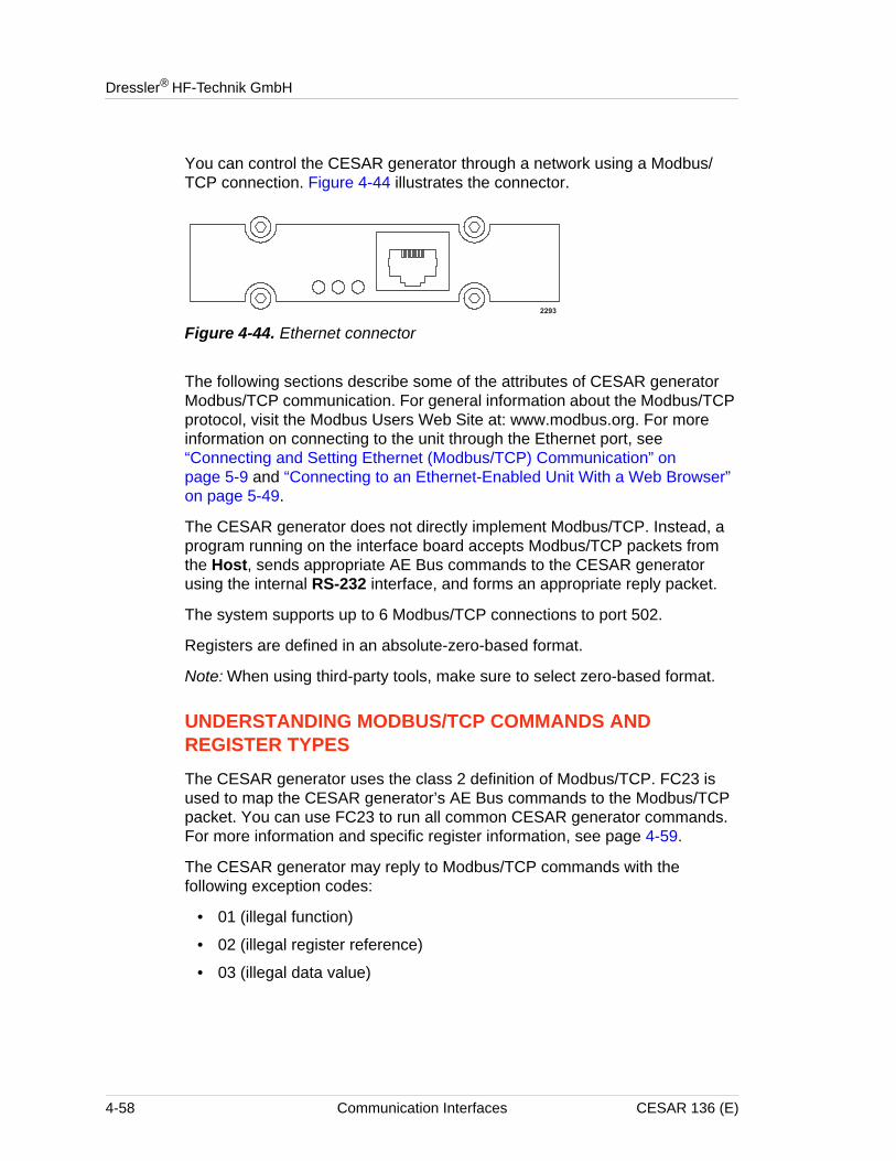
Dressler® HF-Technik GmbH
You can control the CESAR generator through a network using a Modbus/TCP connection. Figure 4-44 illustrates the connector.
Figure 4-44. Ethernet connector
The following sections describe some of the attributes of CESAR generator Modbus/TCP communication. For general information about the Modbus/TCP protocol, visit the Modbus Users Web Site at: www.modbus.org. For more information on connecting to the unit through the Ethernet port, see “Connecting and Setting Ethernet (Modbus/TCP) Communication” on page 5-9 and “Connecting to an Ethernet-Enabled Unit With a Web Browser” on page 5-49.
The CESAR generator does not directly implement Modbus/TCP. Instead, a program running on the interface board accepts Modbus/TCP packets from the Host, sends appropriate AE Bus commands to the CESAR generator using the internal RS-232 interface, and forms an appropriate reply packet.
The system supports up to 6 Modbus/TCP connections to port 502.
Registers are defined in an absolute-zero-based format.
Note: When using third-party tools, make sure to select zero-based format.
UNDERSTANDING MODBUS/TCP COMMANDS AND REGISTER TYPES
The CESAR generator uses the class 2 definition of Modbus/TCP. FC23 is used to map the CESAR generator’s AE Bus commands to the Modbus/TCP packet. You can use FC23 to run all common CESAR generator commands. For more information and specific register information, see page 4-59.
The CESAR generator may reply to Modbus/TCP commands with the following exception codes:
• 01 (illegal function)
• 02 (illegal register reference)
• 03 (illegal data value)
4-58 Communication Interfaces CESAR 136 (E)
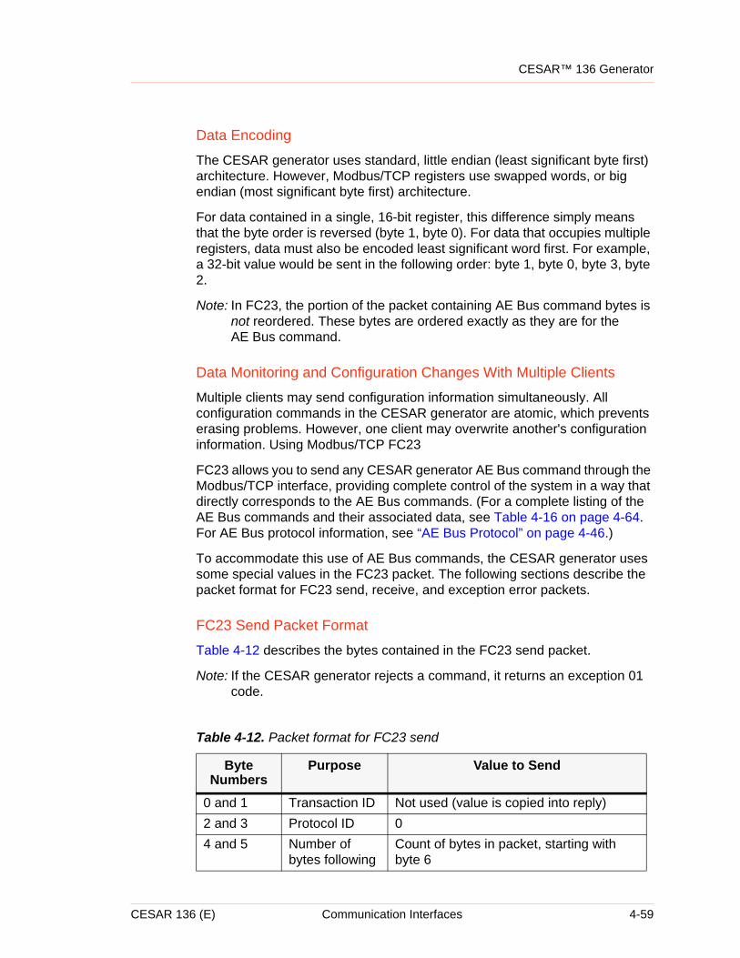
CESAR™ 136 Generator
Data Encoding
The CESAR generator uses standard, little endian (least significant byte first) architecture. However, Modbus/TCP registers use swapped words, or big endian (most significant byte first) architecture.
For data contained in a single, 16-bit register, this difference simply means that the byte order is reversed (byte 1, byte 0). For data that occupies multiple registers, data must also be encoded least significant word first. For example, a 32-bit value would be sent in the following order: byte 1, byte 0, byte 3, byte 2.
Note: In FC23, the portion of the packet containing AE Bus command bytes is not reordered. These bytes are ordered exactly as they are for the AE Bus command.
Data Monitoring and Configuration Changes With Multiple Clients
Multiple clients may send configuration information simultaneously. All configuration commands in the CESAR generator are atomic, which prevents erasing problems. However, one client may overwrite another's configuration information. Using Modbus/TCP FC23
FC23 allows you to send any CESAR generator AE Bus command through the Modbus/TCP interface, providing complete control of the system in a way that directly corresponds to the AE Bus commands. (For a complete listing of the AE Bus commands and their associated data, see Table 4-16 on page 4-64. For AE Bus protocol information, see “AE Bus Protocol” on page 4-46.)
To accommodate this use of AE Bus commands, the CESAR generator uses some special values in the FC23 packet. The following sections describe the packet format for FC23 send, receive, and exception error packets.
FC23 Send Packet Format
Table 4-12 describes the bytes contained in the FC23 send packet.
Note: If the CESAR generator rejects a command, it returns an exception 01 code.
Table 4-12. Packet format for FC23 send
Byte Numbers
Purpose Value to Send
0 and 1 Transaction ID Not used (value is copied into reply)2 and 3 Protocol ID 04 and 5 Number of
bytes followingCount of bytes in packet, starting with byte 6
CESAR 136 (E) Communication Interfaces 4-59
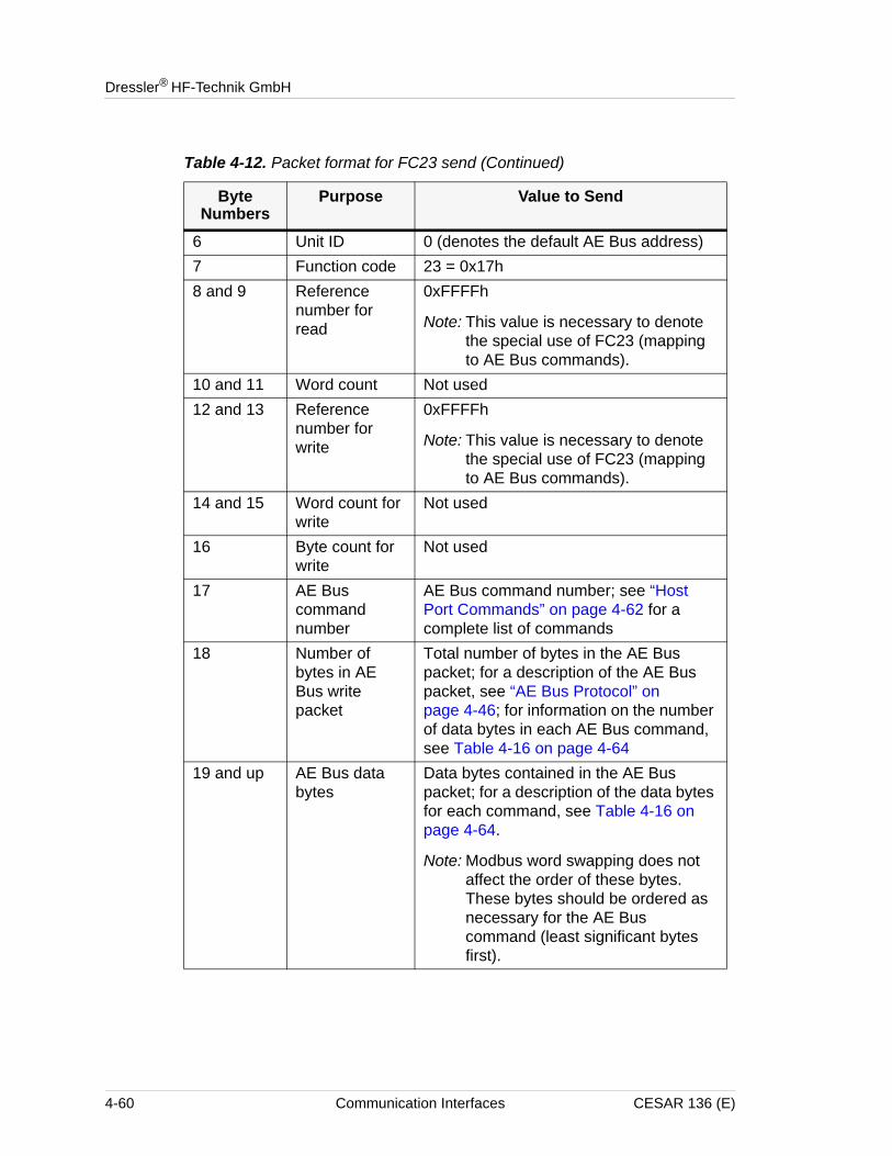
Dressler® HF-Technik GmbH
6 Unit ID 0 (denotes the default AE Bus address)7 Function code 23 = 0x17h8 and 9 Reference
number for read
0xFFFFh
Note: This value is necessary to denote the special use of FC23 (mapping to AE Bus commands).
10 and 11 Word count Not used12 and 13 Reference
number for write
0xFFFFh
Note: This value is necessary to denote the special use of FC23 (mapping to AE Bus commands).
14 and 15 Word count for write
Not used
16 Byte count for write
Not used
17 AE Bus command number
AE Bus command number; see “Host Port Commands” on page 4-62 for a complete list of commands
18 Number of bytes in AE Bus write packet
Total number of bytes in the AE Bus packet; for a description of the AE Bus packet, see “AE Bus Protocol” on page 4-46; for information on the number of data bytes in each AE Bus command, see Table 4-16 on page 4-64
19 and up AE Bus data bytes
Data bytes contained in the AE Bus packet; for a description of the data bytes for each command, see Table 4-16 on page 4-64.
Note: Modbus word swapping does not affect the order of these bytes. These bytes should be ordered as necessary for the AE Bus command (least significant bytes first).
Table 4-12. Packet format for FC23 send (Continued)
Byte Numbers
Purpose Value to Send
4-60 Communication Interfaces CESAR 136 (E)
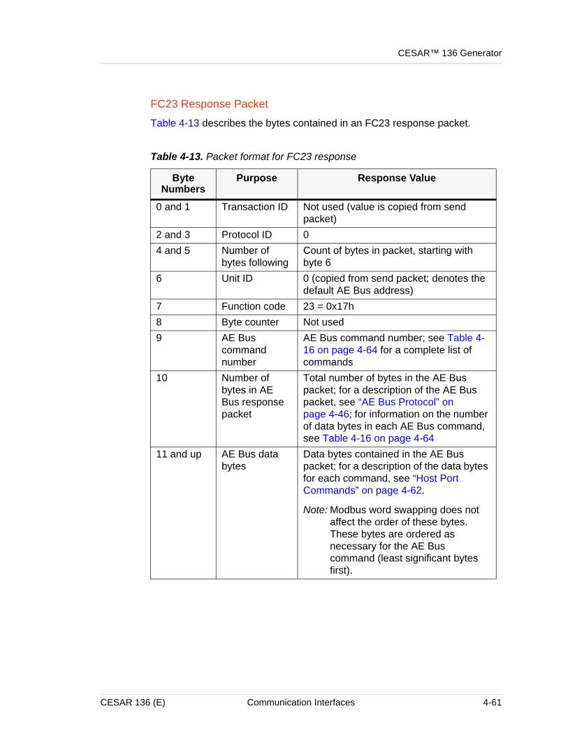
CESAR™ 136 Generator
FC23 Response Packet
Table 4-13 describes the bytes contained in an FC23 response packet.
Table 4-13. Packet format for FC23 response
Byte Numbers
Purpose Response Value
0 and 1 Transaction ID Not used (value is copied from send packet)
2 and 3 Protocol ID 04 and 5 Number of
bytes followingCount of bytes in packet, starting with byte 6
6 Unit ID 0 (copied from send packet; denotes the default AE Bus address)
7 Function code 23 = 0x17h8 Byte counter Not used9 AE Bus
command number
AE Bus command number; see Table 4-16 on page 4-64 for a complete list of commands
10 Number of bytes in AE Bus response packet
Total number of bytes in the AE Bus packet; for a description of the AE Bus packet, see “AE Bus Protocol” on page 4-46; for information on the number of data bytes in each AE Bus command, see Table 4-16 on page 4-64
11 and up AE Bus data bytes
Data bytes contained in the AE Bus packet; for a description of the data bytes for each command, see “Host Port Commands” on page 4-62.
Note: Modbus word swapping does not affect the order of these bytes. These bytes are ordered as necessary for the AE Bus command (least significant bytes first).
CESAR 136 (E) Communication Interfaces 4-61
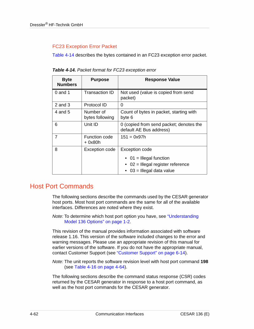
Dressler® HF-Technik GmbH
FC23 Exception Error Packet
Table 4-14 describes the bytes contained in an FC23 exception error packet.
Host Port CommandsThe following sections describe the commands used by the CESAR generator host ports. Most host port commands are the same for all of the available interfaces. Differences are noted where they exist.
Note: To determine which host port option you have, see “Understanding Model 136 Options” on page 1-2.
This revision of the manual provides information associated with software release 1.16. This version of the software included changes to the error and warning messages. Please use an appropriate revision of this manual for earlier versions of the software. If you do not have the appropriate manual, contact Customer Support (see “Customer Support” on page 6-14).
Note: The unit reports the software revision level with host port command 198 (see Table 4-16 on page 4-64).
The following sections describe the command status response (CSR) codes returned by the CESAR generator in response to a host port command, as well as the host port commands for the CESAR generator.
Table 4-14. Packet format for FC23 exception error
Byte Numbers
Purpose Response Value
0 and 1 Transaction ID Not used (value is copied from send packet)
2 and 3 Protocol ID 04 and 5 Number of
bytes followingCount of bytes in packet, starting with byte 6
6 Unit ID 0 (copied from send packet; denotes the default AE Bus address)
7 Function code + 0x80h
151 = 0x97h
8 Exception code Exception code
• 01 = Illegal function• 02 = Illegal register reference• 03 = Illegal data value
4-62 Communication Interfaces CESAR 136 (E)
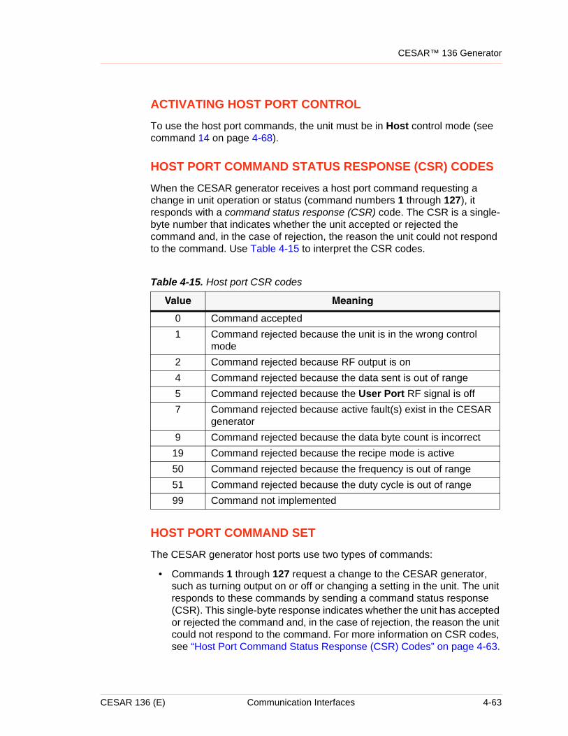
CESAR™ 136 Generator
ACTIVATING HOST PORT CONTROL
To use the host port commands, the unit must be in Host control mode (see command 14 on page 4-68).
HOST PORT COMMAND STATUS RESPONSE (CSR) CODES
When the CESAR generator receives a host port command requesting a change in unit operation or status (command numbers 1 through 127), it responds with a command status response (CSR) code. The CSR is a single-byte number that indicates whether the unit accepted or rejected the command and, in the case of rejection, the reason the unit could not respond to the command. Use Table 4-15 to interpret the CSR codes.
HOST PORT COMMAND SET
The CESAR generator host ports use two types of commands:
• Commands 1 through 127 request a change to the CESAR generator, such as turning output on or off or changing a setting in the unit. The unit responds to these commands by sending a command status response (CSR). This single-byte response indicates whether the unit has accepted or rejected the command and, in the case of rejection, the reason the unit could not respond to the command. For more information on CSR codes, see “Host Port Command Status Response (CSR) Codes” on page 4-63.
Table 4-15. Host port CSR codes
Value Meaning
0 Command accepted1 Command rejected because the unit is in the wrong control
mode2 Command rejected because RF output is on4 Command rejected because the data sent is out of range5 Command rejected because the User Port RF signal is off7 Command rejected because active fault(s) exist in the CESAR
generator9 Command rejected because the data byte count is incorrect
19 Command rejected because the recipe mode is active50 Command rejected because the frequency is out of range51 Command rejected because the duty cycle is out of range99 Command not implemented
CESAR 136 (E) Communication Interfaces 4-63
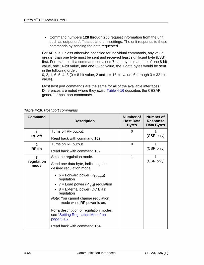
Dressler® HF-Technik GmbH
• Command numbers 128 through 255 request information from the unit, such as output on/off status and unit settings. The unit responds to these commands by sending the data requested.
For AE bus, unless otherwise specified for individual commands, any value greater than one byte must be sent and received least significant byte (LSB) first. For example, if a command contained 7 data bytes made up of one 8-bit value, one 16-bit value, and one 32-bit value, the 7 data bytes would be sent in the following order:0, 2, 1, 6, 5, 4, 3 (0 = 8-bit value, 2 and 1 = 16-bit value, 6 through 3 = 32-bit value).
Most host port commands are the same for all of the available interfaces. Differences are noted where they exist. Table 4-16 describes the CESAR generator host port commands.
Table 4-16. Host port commands
CommandDescription
Number of Host Data
Bytes
Number of Response Data Bytes
1RF off
Turns off RF output.
Read back with command 162.
0 1(CSR only)
2RF on
Turns on RF output
Read back with command 162.
0 1(CSR only)
3 regulation
mode
Sets the regulation mode.
Send one data byte, indicating the desired regulation mode:
• 6 = Forward power (Pforward) regulation
• 7 = Load power (Preal) regulation • 8 = External power (DC Bias)
regulationNote: You cannot change regulation
mode while RF power is on.
For a description of regulation modes, see “Setting Regulation Mode” on page 5-15.
Read back with command 154.
1 1(CSR only)
4-64 Communication Interfaces CESAR 136 (E)
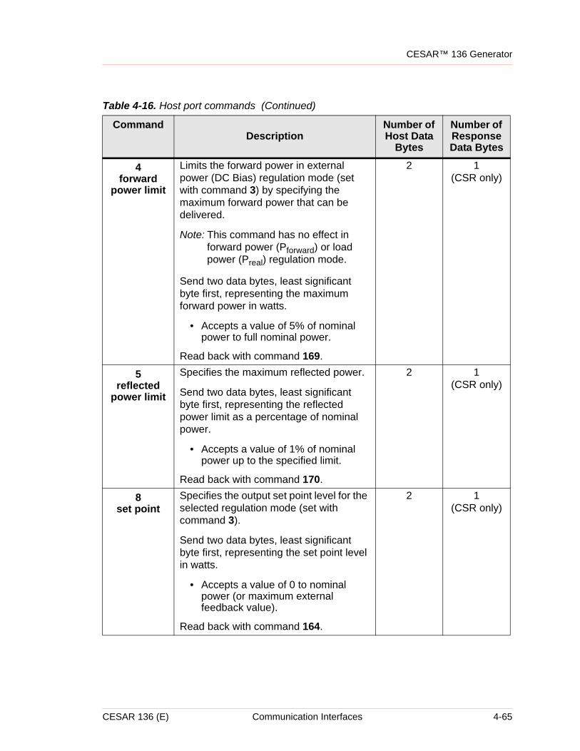
CESAR™ 136 Generator
4forward
power limit
Limits the forward power in external power (DC Bias) regulation mode (set with command 3) by specifying the maximum forward power that can be delivered.
Note: This command has no effect in forward power (Pforward) or load power (Preal) regulation mode.
Send two data bytes, least significant byte first, representing the maximum forward power in watts.
• Accepts a value of 5% of nominal power to full nominal power.
Read back with command 169.
2 1(CSR only)
5reflected
power limit
Specifies the maximum reflected power.
Send two data bytes, least significant byte first, representing the reflected power limit as a percentage of nominal power.
• Accepts a value of 1% of nominal power up to the specified limit.
Read back with command 170.
2 1(CSR only)
8set point
Specifies the output set point level for the selected regulation mode (set with command 3).
Send two data bytes, least significant byte first, representing the set point level in watts.
• Accepts a value of 0 to nominal power (or maximum external feedback value).
Read back with command 164.
2 1(CSR only)
Table 4-16. Host port commands (Continued)
CommandDescription
Number of Host Data
Bytes
Number of Response Data Bytes
CESAR 136 (E) Communication Interfaces 4-65
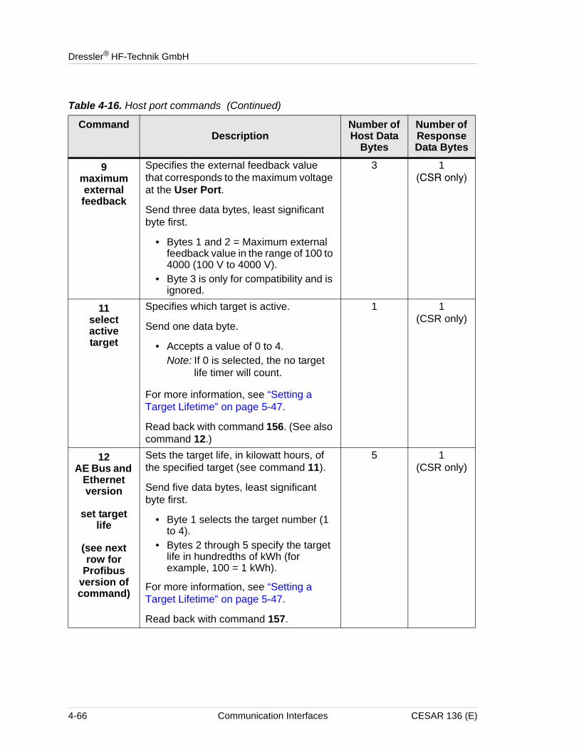
Dressler® HF-Technik GmbH
9maximum external feedback
Specifies the external feedback value that corresponds to the maximum voltage at the User Port.
Send three data bytes, least significant byte first.
• Bytes 1 and 2 = Maximum external feedback value in the range of 100 to 4000 (100 V to 4000 V).
• Byte 3 is only for compatibility and is ignored.
3 1(CSR only)
11select active target
Specifies which target is active.
Send one data byte.
• Accepts a value of 0 to 4.Note: If 0 is selected, the no target
life timer will count.
For more information, see “Setting a Target Lifetime” on page 5-47.
Read back with command 156. (See also command 12.)
1 1(CSR only)
12AE Bus and
Ethernet version
set target life
(see next row for
Profibus version of command)
Sets the target life, in kilowatt hours, of the specified target (see command 11).
Send five data bytes, least significant byte first.
• Byte 1 selects the target number (1 to 4).
• Bytes 2 through 5 specify the target life in hundredths of kWh (for example, 100 = 1 kWh).
For more information, see “Setting a Target Lifetime” on page 5-47.
Read back with command 157.
5 1(CSR only)
Table 4-16. Host port commands (Continued)
CommandDescription
Number of Host Data
Bytes
Number of Response Data Bytes
4-66 Communication Interfaces CESAR 136 (E)
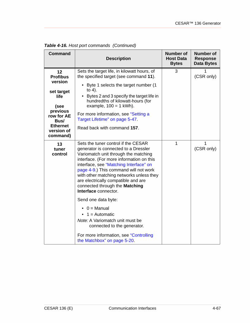
CESAR™ 136 Generator
12Profibus version
set target life
(see previous
row for AE Bus/
Ethernet version of command)
Sets the target life, in kilowatt hours, of the specified target (see command 11).
• Byte 1 selects the target number (1 to 4).
• Bytes 2 and 3 specify the target life in hundredths of kilowatt-hours (for example, 100 = 1 kWh).
For more information, see “Setting a Target Lifetime” on page 5-47.
Read back with command 157.
3 1(CSR only)
13tuner
control
Sets the tuner control if the CESAR generator is connected to a Dressler Variomatch unit through the matching interface. (For more information on this interface, see “Matching Interface” on page 4-9.) This command will not work with other matching networks unless they are electrically compatible and are connected through the Matching Interface connector.
Send one data byte:
• 0 = Manual• 1 = Automatic
Note: A Variomatch unit must be connected to the generator.
For more information, see “Controlling the Matchbox” on page 5-20.
1 1(CSR only)
Table 4-16. Host port commands (Continued)
CommandDescription
Number of Host Data
Bytes
Number of Response Data Bytes
CESAR 136 (E) Communication Interfaces 4-67
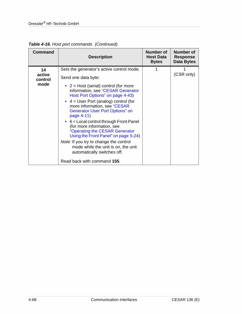
Dressler® HF-Technik GmbH
14active
control mode
Sets the generator’s active control mode.
Send one data byte:
• 2 = Host (serial) control (for more information, see “CESAR Generator Host Port Options” on page 4-43)
• 4 = User Port (analog) control (for more information, see “CESAR Generator User Port Options” on page 4-11)
• 6 = Local control through Front Panel (for more information, see “Operating the CESAR Generator Using the Front Panel” on page 5-24)
Note: If you try to change the control mode while the unit is on, the unit automatically switches off.
Read back with command 155.
1 1(CSR only)
Table 4-16. Host port commands (Continued)
CommandDescription
Number of Host Data
Bytes
Number of Response Data Bytes
4-68 Communication Interfaces CESAR 136 (E)
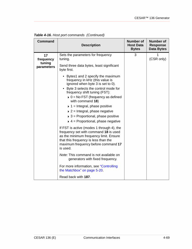
CESAR™ 136 Generator
17frequency
tuning parameters
Sets the parameters for frequency tuning.
Send three data bytes, least significant byte first.
• Bytes1 and 2 specify the maximum frequency in kHz (this value is ignored when byte 3 is set to 0).
• Byte 3 selects the control mode for frequency shift tuning (FST):
40 = No FST (frequency as defined with command 18)
41 = Integral, phase positive
42 = Integral, phase negative
43 = Proportional, phase positive
44 = Proportional, phase negative
If FST is active (modes 1 through 4), the frequency set with command 18 is used as the minimum frequency limit. Ensure that this frequency is less than the maximum frequency before command 17 is used.
Note: This command is not available on generators with fixed frequency.
For more information, see “Controlling the Matchbox” on page 5-20.
Read back with 187.
3 1(CSR only)
Table 4-16. Host port commands (Continued)
CommandDescription
Number of Host Data
Bytes
Number of Response Data Bytes
CESAR 136 (E) Communication Interfaces 4-69
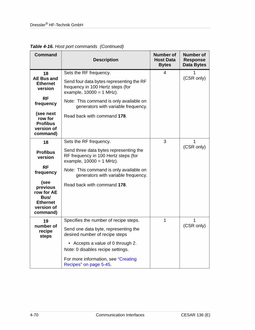
Dressler® HF-Technik GmbH
18AE Bus and
Ethernet version
RF frequency
(see next row for
Profibus version of command)
Sets the RF frequency.
Send four data bytes representing the RF frequency in 100 Hertz steps (for example, 10000 = 1 MHz).
Note: This command is only available on generators with variable frequency.
Read back with command 178.
4 1(CSR only)
18
Profibus version
RF frequency
(see previous
row for AE Bus/
Ethernet version of command)
Sets the RF frequency.
Send three data bytes representing the RF frequency in 100 Hertz steps (for example, 10000 = 1 MHz).
Note: This command is only available on generators with variable frequency.
Read back with command 178.
3 1(CSR only)
19number of
recipe steps
Specifies the number of recipe steps.
Send one data byte, representing the desired number of recipe steps
• Accepts a value of 0 through 2.Note: 0 disables recipe settings.
For more information, see “Creating Recipes” on page 5-45.
1 1(CSR only)
Table 4-16. Host port commands (Continued)
CommandDescription
Number of Host Data
Bytes
Number of Response Data Bytes
4-70 Communication Interfaces CESAR 136 (E)
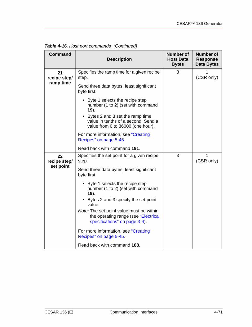
CESAR™ 136 Generator
21recipe step/ramp time
Specifies the ramp time for a given recipe step.
Send three data bytes, least significant byte first:
• Byte 1 selects the recipe step number (1 to 2) (set with command 19).
• Bytes 2 and 3 set the ramp time value in tenths of a second. Send a value from 0 to 36000 (one hour).
For more information, see “Creating Recipes” on page 5-45.
Read back with command 191.
3 1(CSR only)
22recipe step/
set point
Specifies the set point for a given recipe step.
Send three data bytes, least significant byte first.
• Byte 1 selects the recipe step number (1 to 2) (set with command 19).
• Bytes 2 and 3 specify the set point value.
Note: The set point value must be within the operating range (see “Electrical specifications” on page 3-4).
For more information, see “Creating Recipes” on page 5-45.
Read back with command 188.
3 1(CSR only)
Table 4-16. Host port commands (Continued)
CommandDescription
Number of Host Data
Bytes
Number of Response Data Bytes
CESAR 136 (E) Communication Interfaces 4-71
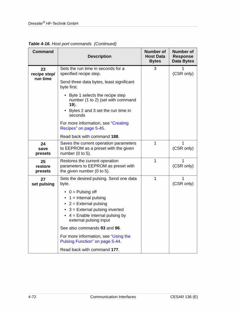
Dressler® HF-Technik GmbH
23recipe step/
run time
Sets the run time in seconds for a specified recipe step.
Send three data bytes, least significant byte first.
• Byte 1 selects the recipe step number (1 to 2) (set with command 19).
• Bytes 2 and 3 set the run time in seconds
For more information, see “Creating Recipes” on page 5-45.
Read back with command 188.
3 1(CSR only)
24save
presets
Saves the current operation parameters to EEPROM as a preset with the given number (0 to 5).
1 1(CSR only)
25restore presets
Restores the current operation parameters to EEPROM as preset with the given number (0 to 5).
1 1(CSR only)
27set pulsing
Sets the desired pulsing. Send one data byte.
• 0 = Pulsing off• 1 = Internal pulsing• 2 = External pulsing• 3 = External pulsing inverted• 4 = Enable internal pulsing by
external pulsing input
See also commands 93 and 96.
For more information, see “Using the Pulsing Function” on page 5-44.
Read back with command 177.
1 1(CSR only)
Table 4-16. Host port commands (Continued)
CommandDescription
Number of Host Data
Bytes
Number of Response Data Bytes
4-72 Communication Interfaces CESAR 136 (E)
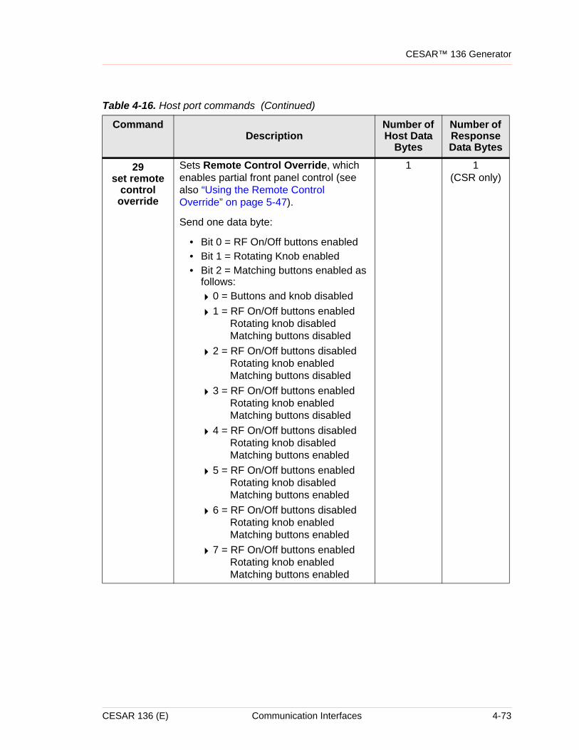
CESAR™ 136 Generator
29set remote
control override
Sets Remote Control Override, which enables partial front panel control (see also “Using the Remote Control Override” on page 5-47).
Send one data byte:
• Bit 0 = RF On/Off buttons enabled• Bit 1 = Rotating Knob enabled• Bit 2 = Matching buttons enabled as
follows:
40 = Buttons and knob disabled
41 = RF On/Off buttons enabledRotating knob disabledMatching buttons disabled
42 = RF On/Off buttons disabledRotating knob enabledMatching buttons disabled
43 = RF On/Off buttons enabledRotating knob enabledMatching buttons disabled
44 = RF On/Off buttons disabledRotating knob disabledMatching buttons enabled
45 = RF On/Off buttons enabledRotating knob disabledMatching buttons enabled
46 = RF On/Off buttons disabledRotating knob enabledMatching buttons enabled
47 = RF On/Off buttons enabledRotating knob enabledMatching buttons enabled
1 1(CSR only)
Table 4-16. Host port commands (Continued)
CommandDescription
Number of Host Data
Bytes
Number of Response Data Bytes
CESAR 136 (E) Communication Interfaces 4-73
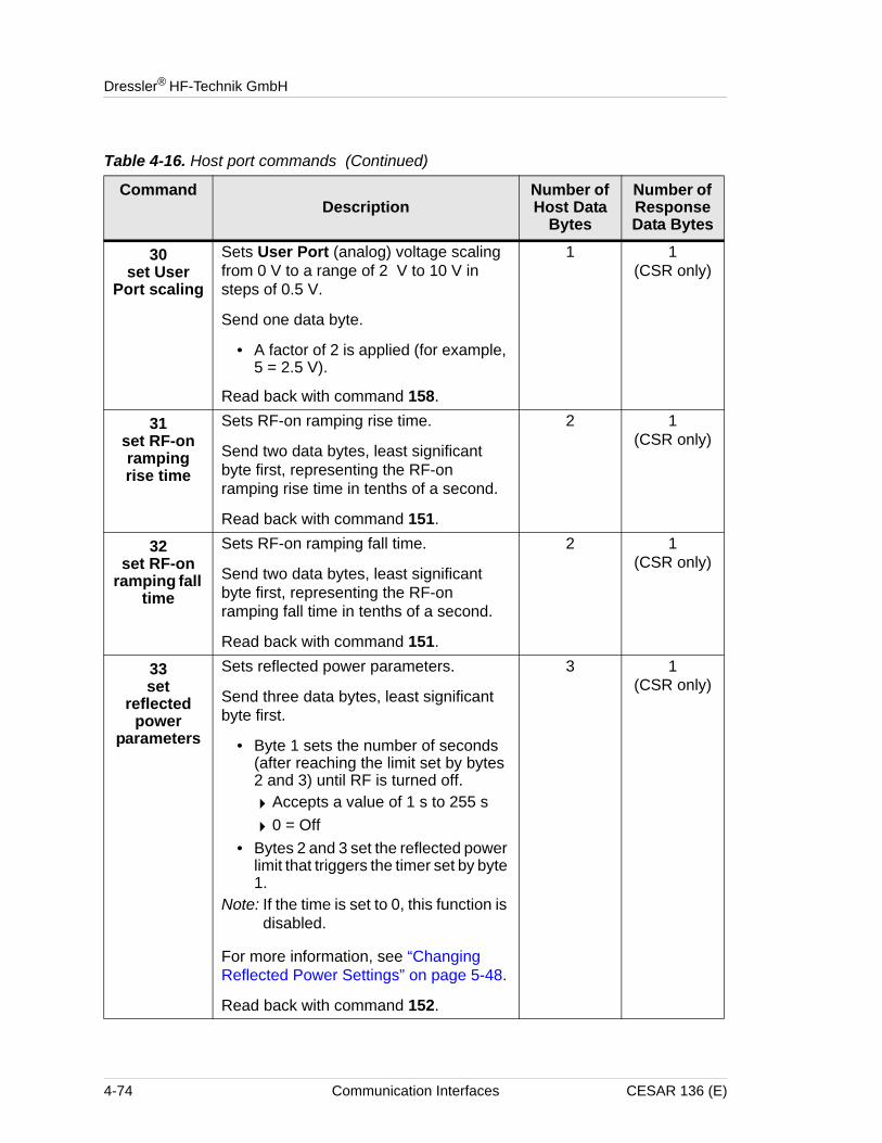
Dressler® HF-Technik GmbH
30set User
Port scaling
Sets User Port (analog) voltage scaling from 0 V to a range of 2 V to 10 V in steps of 0.5 V.
Send one data byte.
• A factor of 2 is applied (for example, 5 = 2.5 V).
Read back with command 158.
1 1(CSR only)
31set RF-on ramping rise time
Sets RF-on ramping rise time.
Send two data bytes, least significant byte first, representing the RF-on ramping rise time in tenths of a second.
Read back with command 151.
2 1(CSR only)
32set RF-on
ramping fall time
Sets RF-on ramping fall time.
Send two data bytes, least significant byte first, representing the RF-on ramping fall time in tenths of a second.
Read back with command 151.
2 1(CSR only)
33set
reflected power
parameters
Sets reflected power parameters.
Send three data bytes, least significant byte first.
• Byte 1 sets the number of seconds (after reaching the limit set by bytes 2 and 3) until RF is turned off.
4Accepts a value of 1 s to 255 s
40 = Off• Bytes 2 and 3 set the reflected power
limit that triggers the timer set by byte 1.
Note: If the time is set to 0, this function is disabled.
For more information, see “Changing Reflected Power Settings” on page 5-48.
Read back with command 152.
3 1(CSR only)
Table 4-16. Host port commands (Continued)
CommandDescription
Number of Host Data
Bytes
Number of Response Data Bytes
4-74 Communication Interfaces CESAR 136 (E)
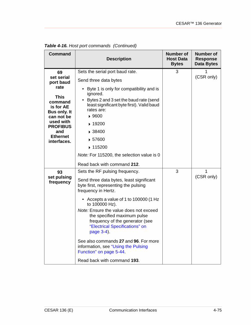
CESAR™ 136 Generator
69set serial port baud
rate
This command is for AE
Bus only. It can not be used with PROFIBUS
and Ethernet
interfaces.
Sets the serial port baud rate.
Send three data bytes
• Byte 1 is only for compatibility and is ignored.
• Bytes 2 and 3 set the baud rate (send least significant byte first). Valid baud rates are:
49600
419200
438400
457600
4115200
Note: For 115200, the selection value is 0
Read back with command 212.
3 1(CSR only)
93set pulsing frequency
Sets the RF pulsing frequency.
Send three data bytes, least significant byte first, representing the pulsing frequency in Hertz.
• Accepts a value of 1 to 100000 (1 Hz to 100000 Hz).
Note: Ensure the value does not exceed the specified maximum pulse frequency of the generator (see “Electrical Specifications” on page 3-4).
See also commands 27 and 96. For more information, see “Using the Pulsing Function” on page 5-44.
Read back with command 193.
3 1(CSR only)
Table 4-16. Host port commands (Continued)
CommandDescription
Number of Host Data
Bytes
Number of Response Data Bytes
CESAR 136 (E) Communication Interfaces 4-75
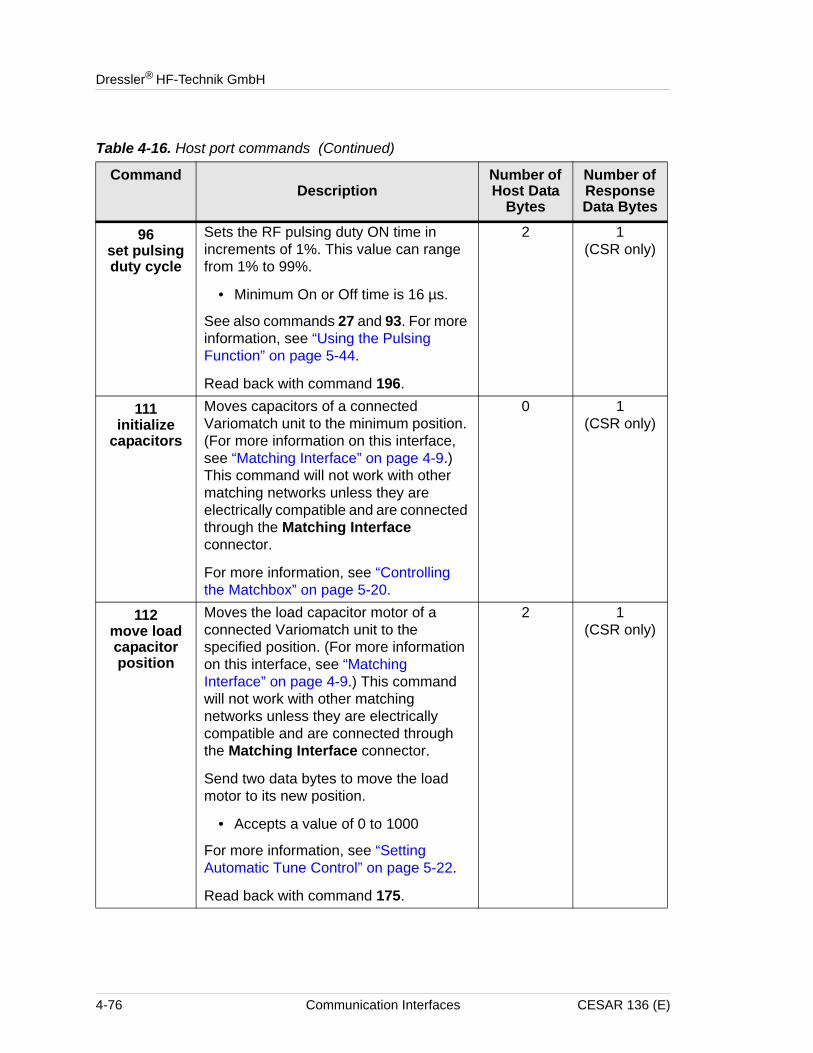
Dressler® HF-Technik GmbH
96set pulsing duty cycle
Sets the RF pulsing duty ON time in increments of 1%. This value can range from 1% to 99%.
• Minimum On or Off time is 16 µs.
See also commands 27 and 93. For more information, see “Using the Pulsing Function” on page 5-44.
Read back with command 196.
2 1(CSR only)
111initialize
capacitors
Moves capacitors of a connected Variomatch unit to the minimum position. (For more information on this interface, see “Matching Interface” on page 4-9.) This command will not work with other matching networks unless they are electrically compatible and are connected through the Matching Interface connector.
For more information, see “Controlling the Matchbox” on page 5-20.
0 1(CSR only)
112move load capacitor position
Moves the load capacitor motor of a connected Variomatch unit to the specified position. (For more information on this interface, see “Matching Interface” on page 4-9.) This command will not work with other matching networks unless they are electrically compatible and are connected through the Matching Interface connector.
Send two data bytes to move the load motor to its new position.
• Accepts a value of 0 to 1000
For more information, see “Setting Automatic Tune Control” on page 5-22.
Read back with command 175.
2 1(CSR only)
Table 4-16. Host port commands (Continued)
CommandDescription
Number of Host Data
Bytes
Number of Response Data Bytes
4-76 Communication Interfaces CESAR 136 (E)
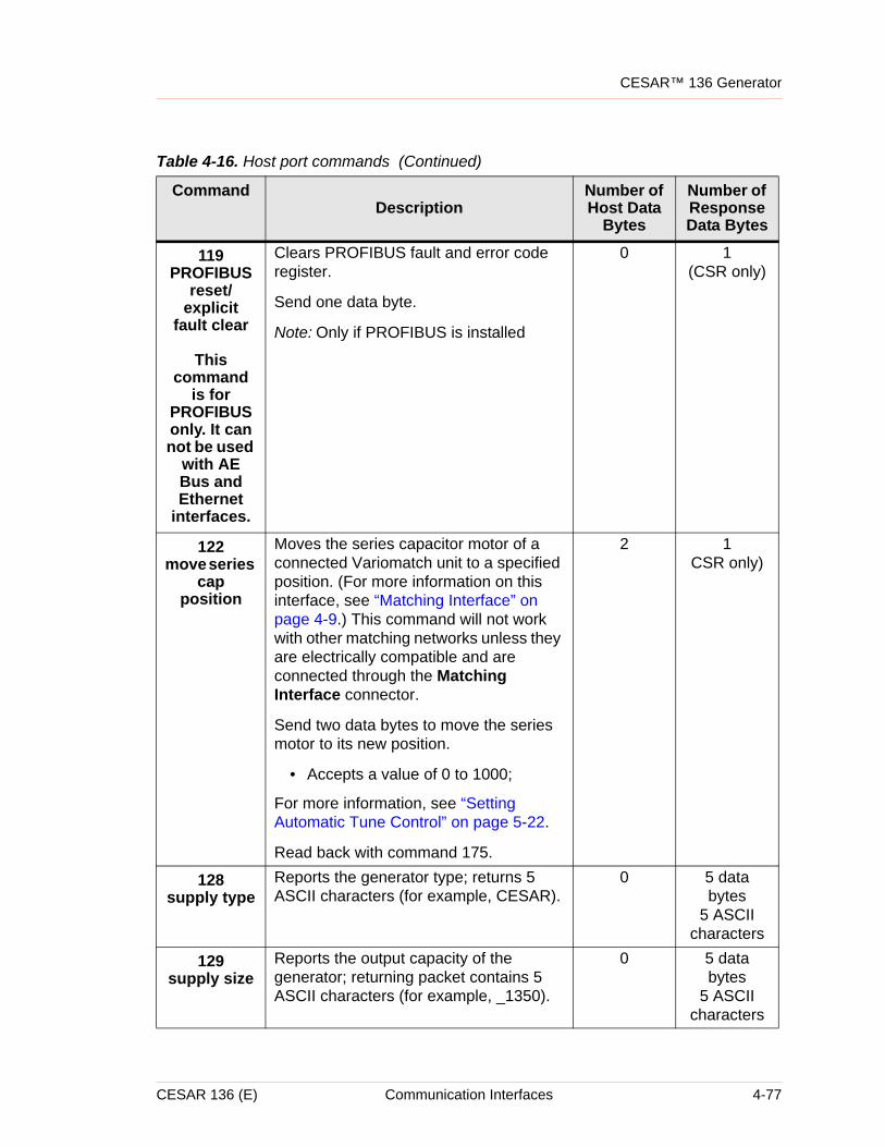
CESAR™ 136 Generator
119PROFIBUS
reset/explicit
fault clear
This command
is for PROFIBUS only. It can not be used
with AE Bus and Ethernet
interfaces.
Clears PROFIBUS fault and error code register.
Send one data byte.
Note: Only if PROFIBUS is installed
0 1(CSR only)
122move series
cap position
Moves the series capacitor motor of a connected Variomatch unit to a specified position. (For more information on this interface, see “Matching Interface” on page 4-9.) This command will not work with other matching networks unless they are electrically compatible and are connected through the Matching Interface connector.
Send two data bytes to move the series motor to its new position.
• Accepts a value of 0 to 1000;
For more information, see “Setting Automatic Tune Control” on page 5-22.
Read back with command 175.
2 1CSR only)
128supply type
Reports the generator type; returns 5 ASCII characters (for example, CESAR).
0 5 data bytes
5 ASCII characters
129supply size
Reports the output capacity of the generator; returning packet contains 5 ASCII characters (for example, _1350).
0 5 data bytes
5 ASCII characters
Table 4-16. Host port commands (Continued)
CommandDescription
Number of Host Data
Bytes
Number of Response Data Bytes
CESAR 136 (E) Communication Interfaces 4-77
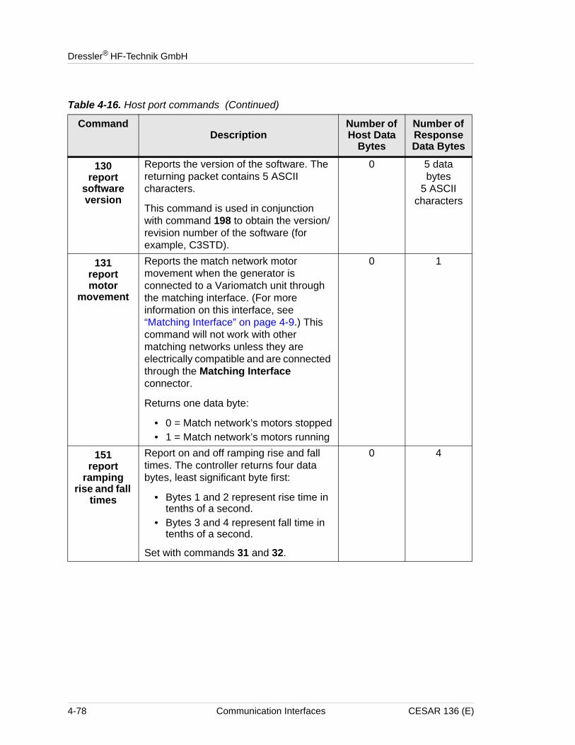
Dressler® HF-Technik GmbH
130report
software version
Reports the version of the software. The returning packet contains 5 ASCII characters.
This command is used in conjunction with command 198 to obtain the version/revision number of the software (for example, C3STD).
0 5 data bytes
5 ASCII characters
131report motor
movement
Reports the match network motor movement when the generator is connected to a Variomatch unit through the matching interface. (For more information on this interface, see “Matching Interface” on page 4-9.) This command will not work with other matching networks unless they are electrically compatible and are connected through the Matching Interface connector.
Returns one data byte:
• 0 = Match network’s motors stopped• 1 = Match network’s motors running
0 1
151report
ramping rise and fall
times
Report on and off ramping rise and fall times. The controller returns four data bytes, least significant byte first:
• Bytes 1 and 2 represent rise time in tenths of a second.
• Bytes 3 and 4 represent fall time in tenths of a second.
Set with commands 31 and 32.
0 4
Table 4-16. Host port commands (Continued)
CommandDescription
Number of Host Data
Bytes
Number of Response Data Bytes
4-78 Communication Interfaces CESAR 136 (E)
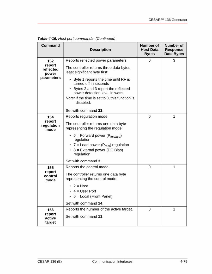
CESAR™ 136 Generator
152report
reflected power
parameters
Reports reflected power parameters.
The controller returns three data bytes, least significant byte first:
• Byte 1 reports the time until RF is turned off in seconds
• Bytes 2 and 3 report the reflected power detection level in watts.
Note: If the time is set to 0, this function is disabled.
Set with command 33.
0 3
154report
regulation mode
Reports regulation mode.
The controller returns one data byte representing the regulation mode:
• 6 = Forward power (Pforward) regulation
• 7 = Load power (Preal) regulation• 8 = External power (DC Bias)
regulation
Set with command 3.
0 1
155report control mode
Reports the control mode.
The controller returns one data byte representing the control mode:
• 2 = Host• 4 = User Port• 6 = Local (Front Panel)
Set with command 14.
0 1
156report active target
Reports the number of the active target.
Set with command 11.
0 1
Table 4-16. Host port commands (Continued)
CommandDescription
Number of Host Data
Bytes
Number of Response Data Bytes
CESAR 136 (E) Communication Interfaces 4-79
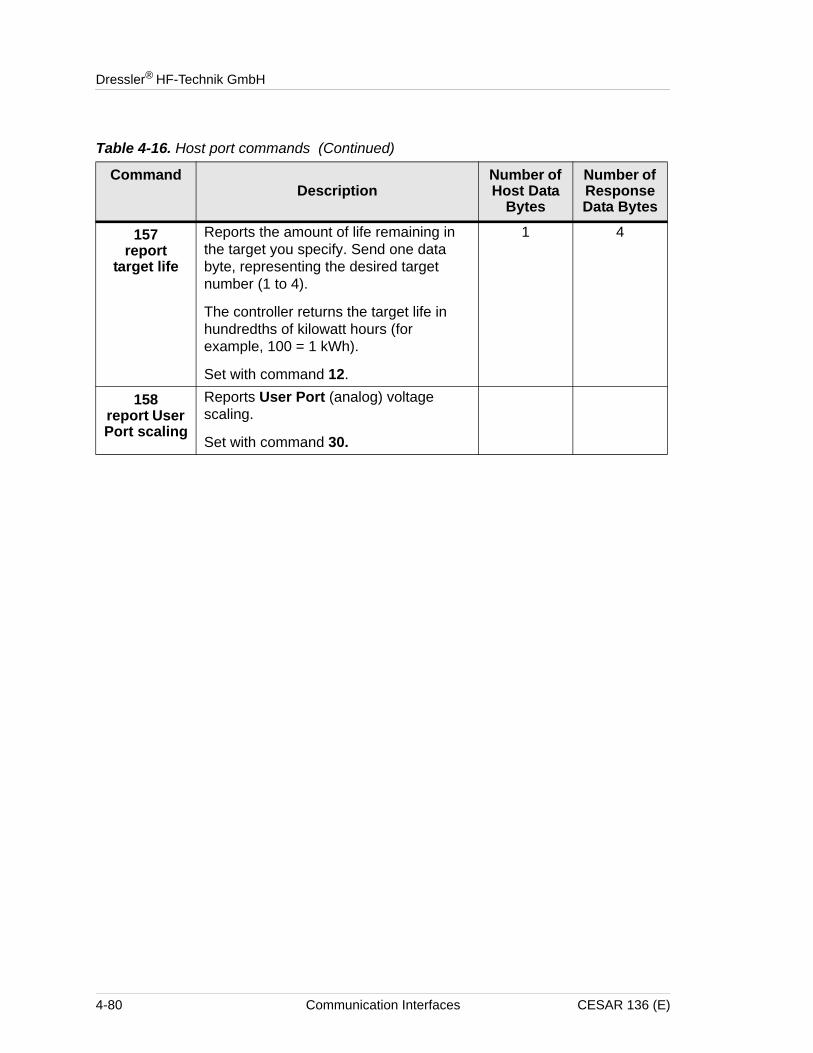
Dressler® HF-Technik GmbH
157report
target life
Reports the amount of life remaining in the target you specify. Send one data byte, representing the desired target number (1 to 4).
The controller returns the target life in hundredths of kilowatt hours (for example, 100 = 1 kWh).
Set with command 12.
1 4
158report User Port scaling
Reports User Port (analog) voltage scaling.
Set with command 30.
Table 4-16. Host port commands (Continued)
CommandDescription
Number of Host Data
Bytes
Number of Response Data Bytes
4-80 Communication Interfaces CESAR 136 (E)
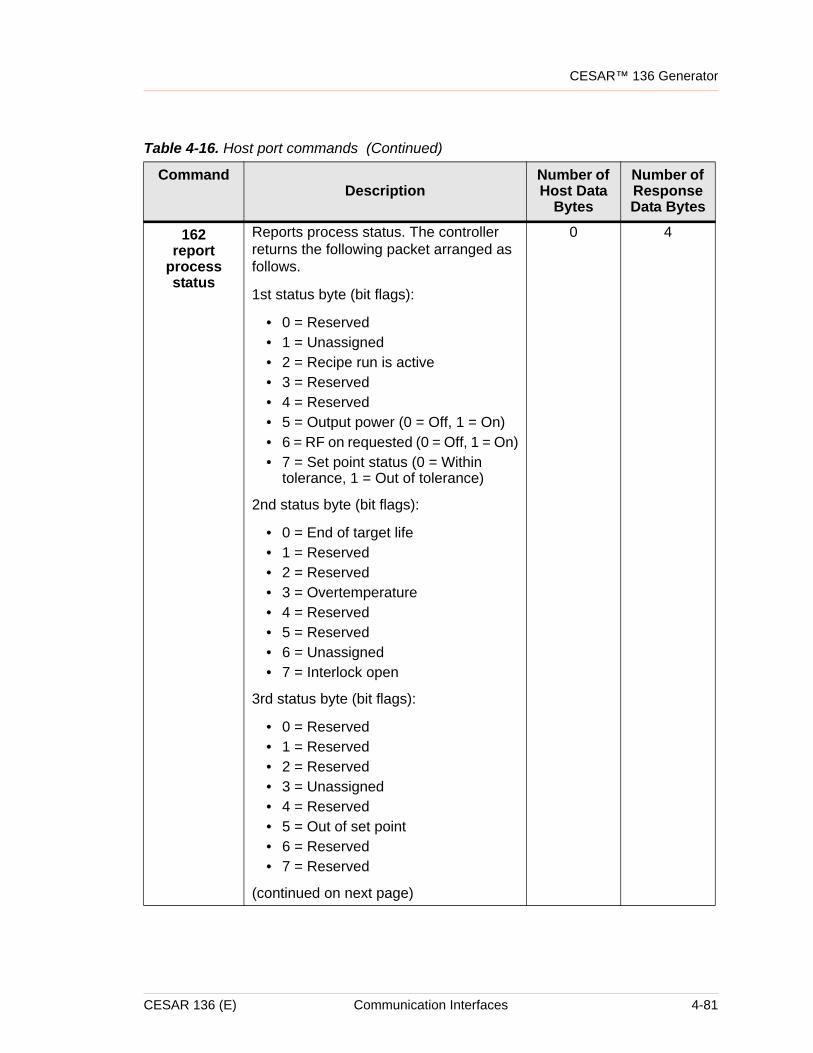
CESAR™ 136 Generator
162report
process status
Reports process status. The controller returns the following packet arranged as follows.
1st status byte (bit flags):
• 0 = Reserved• 1 = Unassigned• 2 = Recipe run is active• 3 = Reserved• 4 = Reserved• 5 = Output power (0 = Off, 1 = On)• 6 = RF on requested (0 = Off, 1 = On)• 7 = Set point status (0 = Within
tolerance, 1 = Out of tolerance)
2nd status byte (bit flags):
• 0 = End of target life• 1 = Reserved• 2 = Reserved• 3 = Overtemperature• 4 = Reserved• 5 = Reserved• 6 = Unassigned• 7 = Interlock open
3rd status byte (bit flags):
• 0 = Reserved• 1 = Reserved• 2 = Reserved• 3 = Unassigned• 4 = Reserved• 5 = Out of set point• 6 = Reserved• 7 = Reserved
(continued on next page)
0 4
Table 4-16. Host port commands (Continued)
CommandDescription
Number of Host Data
Bytes
Number of Response Data Bytes
CESAR 136 (E) Communication Interfaces 4-81
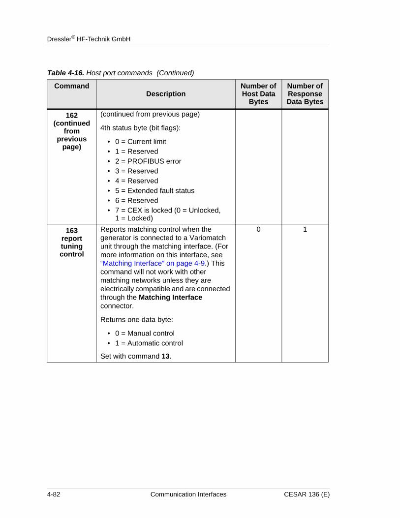
Dressler® HF-Technik GmbH
162(continued
from previous
page)
(continued from previous page)
4th status byte (bit flags):
• 0 = Current limit• 1 = Reserved• 2 = PROFIBUS error• 3 = Reserved• 4 = Reserved• 5 = Extended fault status• 6 = Reserved• 7 = CEX is locked (0 = Unlocked,
1 = Locked)
163report tuning control
Reports matching control when the generator is connected to a Variomatch unit through the matching interface. (For more information on this interface, see “Matching Interface” on page 4-9.) This command will not work with other matching networks unless they are electrically compatible and are connected through the Matching Interface connector.
Returns one data byte:
• 0 = Manual control• 1 = Automatic control
Set with command 13.
0 1
Table 4-16. Host port commands (Continued)
CommandDescription
Number of Host Data
Bytes
Number of Response Data Bytes
4-82 Communication Interfaces CESAR 136 (E)
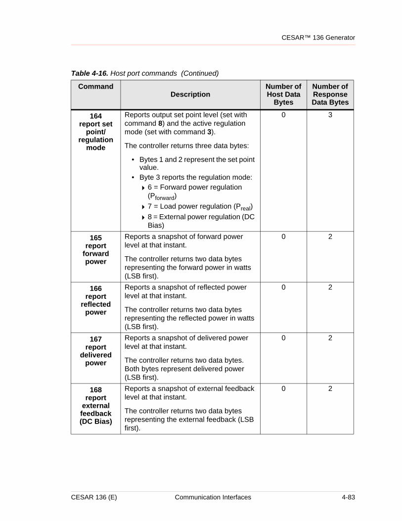
CESAR™ 136 Generator
164report set
point/regulation
mode
Reports output set point level (set with command 8) and the active regulation mode (set with command 3).
The controller returns three data bytes:
• Bytes 1 and 2 represent the set point value.
• Byte 3 reports the regulation mode:
46 = Forward power regulation (Pforward)
47 = Load power regulation (Preal)
48 = External power regulation (DC Bias)
0 3
165report
forward power
Reports a snapshot of forward power level at that instant.
The controller returns two data bytes representing the forward power in watts (LSB first).
0 2
166report
reflected power
Reports a snapshot of reflected power level at that instant.
The controller returns two data bytes representing the reflected power in watts (LSB first).
0 2
167report
delivered power
Reports a snapshot of delivered power level at that instant.
The controller returns two data bytes. Both bytes represent delivered power (LSB first).
0 2
168report
external feedback (DC Bias)
Reports a snapshot of external feedback level at that instant.
The controller returns two data bytes representing the external feedback (LSB first).
0 2
Table 4-16. Host port commands (Continued)
CommandDescription
Number of Host Data
Bytes
Number of Response Data Bytes
CESAR 136 (E) Communication Interfaces 4-83
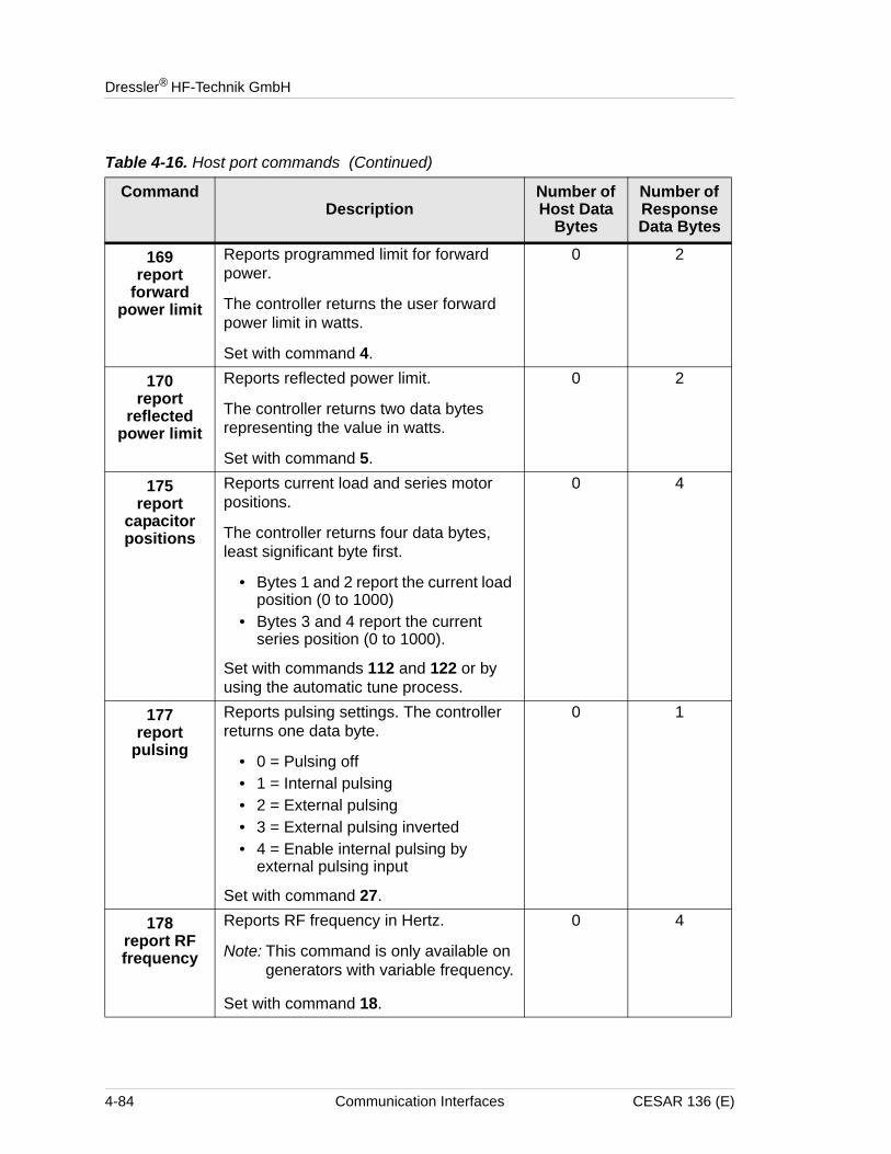
Dressler® HF-Technik GmbH
169report
forward power limit
Reports programmed limit for forward power.
The controller returns the user forward power limit in watts.
Set with command 4.
0 2
170report
reflected power limit
Reports reflected power limit.
The controller returns two data bytes representing the value in watts.
Set with command 5.
0 2
175report
capacitor positions
Reports current load and series motor positions.
The controller returns four data bytes, least significant byte first.
• Bytes 1 and 2 report the current load position (0 to 1000)
• Bytes 3 and 4 report the current series position (0 to 1000).
Set with commands 112 and 122 or by using the automatic tune process.
0 4
177report
pulsing
Reports pulsing settings. The controller returns one data byte.
• 0 = Pulsing off• 1 = Internal pulsing• 2 = External pulsing• 3 = External pulsing inverted• 4 = Enable internal pulsing by
external pulsing input
Set with command 27.
0 1
178report RF frequency
Reports RF frequency in Hertz.
Note: This command is only available on generators with variable frequency.
Set with command 18.
0 4
Table 4-16. Host port commands (Continued)
CommandDescription
Number of Host Data
Bytes
Number of Response Data Bytes
4-84 Communication Interfaces CESAR 136 (E)
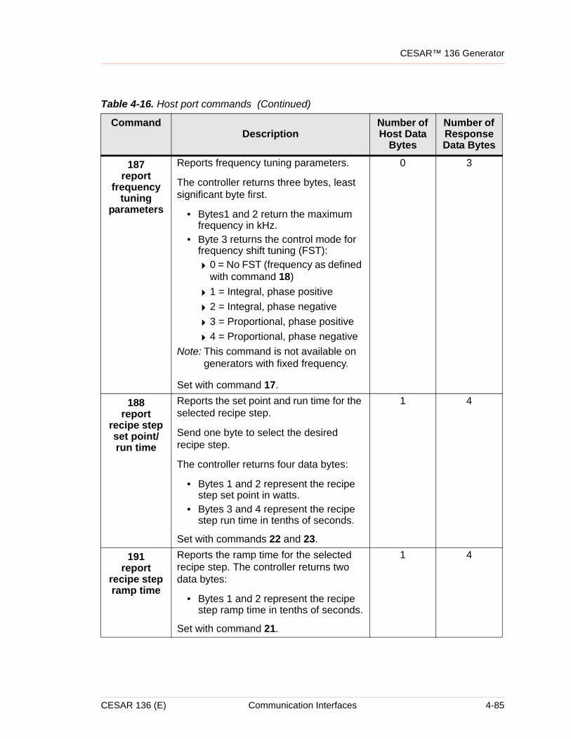
CESAR™ 136 Generator
187report
frequency tuning
parameters
Reports frequency tuning parameters.
The controller returns three bytes, least significant byte first.
• Bytes1 and 2 return the maximum frequency in kHz.
• Byte 3 returns the control mode for frequency shift tuning (FST):
40 = No FST (frequency as defined with command 18)
41 = Integral, phase positive
42 = Integral, phase negative
43 = Proportional, phase positive
44 = Proportional, phase negativeNote: This command is not available on
generators with fixed frequency.
Set with command 17.
0 3
188report
recipe step set point/run time
Reports the set point and run time for the selected recipe step.
Send one byte to select the desired recipe step.
The controller returns four data bytes:
• Bytes 1 and 2 represent the recipe step set point in watts.
• Bytes 3 and 4 represent the recipe step run time in tenths of seconds.
Set with commands 22 and 23.
1 4
191report
recipe step ramp time
Reports the ramp time for the selected recipe step. The controller returns two data bytes:
• Bytes 1 and 2 represent the recipe step ramp time in tenths of seconds.
Set with command 21.
1 4
Table 4-16. Host port commands (Continued)
CommandDescription
Number of Host Data
Bytes
Number of Response Data Bytes
CESAR 136 (E) Communication Interfaces 4-85
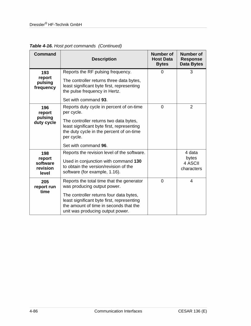
Dressler® HF-Technik GmbH
193report
pulsing frequency
Reports the RF pulsing frequency.
The controller returns three data bytes, least significant byte first, representing the pulse frequency in Hertz.
Set with command 93.
0 3
196report
pulsing duty cycle
Reports duty cycle in percent of on-time per cycle.
The controller returns two data bytes, least significant byte first, representing the duty cycle in the percent of on-time per cycle.
Set with command 96.
0 2
198report
software revision
level
Reports the revision level of the software.
Used in conjunction with command 130 to obtain the version/revision of the software (for example, 1.16).
4 data bytes
4 ASCII characters
205report run
time
Reports the total time that the generator was producing output power.
The controller returns four data bytes, least significant byte first, representing the amount of time in seconds that the unit was producing output power.
0 4
Table 4-16. Host port commands (Continued)
CommandDescription
Number of Host Data
Bytes
Number of Response Data Bytes
4-86 Communication Interfaces CESAR 136 (E)
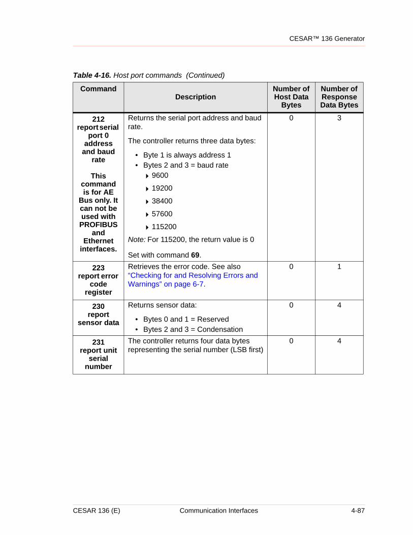
CESAR™ 136 Generator
212report serial
port 0 address
and baud rate
This command is for AE
Bus only. It can not be used with PROFIBUS
and Ethernet
interfaces.
Returns the serial port address and baud rate.
The controller returns three data bytes:
• Byte 1 is always address 1• Bytes 2 and 3 = baud rate
49600
419200
438400
457600
4115200
Note: For 115200, the return value is 0
Set with command 69.
0 3
223report error
code register
Retrieves the error code. See also “Checking for and Resolving Errors and Warnings” on page 6-7.
0 1
230report
sensor data
Returns sensor data:
• Bytes 0 and 1 = Reserved• Bytes 2 and 3 = Condensation
0 4
231report unit
serial number
The controller returns four data bytes representing the serial number (LSB first)
0 4
Table 4-16. Host port commands (Continued)
CommandDescription
Number of Host Data
Bytes
Number of Response Data Bytes
CESAR 136 (E) Communication Interfaces 4-87
Dressler® HF-Technik GmbH
4-88 Communication Interfaces CESAR 136 (E)
ChapterCESAR™ 136 Generator
Chapter
5
Installation, Setup, and OperationPREPARING TO INSTALL THE CESAR GENERATOR
The following sections provide information that you need to understand before installing the CESAR generator.
Spacing RequirementsThe CESAR generator is designed for 19" racks but may be used alternatively as a desktop model. Regardless, you must ensure proper air flow (see “Cooling Specifications” on page 3-6):
• 6 cm (2.4") required on the left and right sides for airflow• 10.16 cm (4″ ) required at rear for cable connections
Additional space for connectors and cabling can be necessary. Also, allow adequate space for anyone who may need to access the front and rear panels. For a dimensional drawing, see “Unit Dimensions” on page 3-2.
CESAR 136 (E) Installation, Setup, and Operation 5-1
Dressler® HF-Technik GmbH
Installation RequirementsInstall this unit according to the following requirements.
Tools Required for InstallationDressler supplies the following equipment:
• The CESAR™ 136 Generator
• An AC Mains cable
For successful installation, you will need to supply the following additional equipment:
• 19” rack or stable mounting surface
• 4 mounting screws (if you are rack-mounting the unit) and an appropriate screwdriver
• A matching network (if you are using the generator with a matching network). The CESAR generator is compatible with a Dressler Variomatch or a matching network with the same control functions and electronic topology.
• Cables (see also “Connector/Cable specifications” on page 3-3):
4Grounding cable
4Shielded coaxial cable for RF output
Operating and maintenance personnel must receive proper training before installing, troubleshooting, or maintaining high-energy electrical equipment. Potentially lethal voltages could cause death, serious personal injury, or damage to the equipment. Ensure that all appropriate safety precautions are taken.
RISK OF DEATH OR BODILY INJURY. Disconnect and lockout/tagout all sources of input power before working on this unit or anything connected to it.
5-2 Installation, Setup, and Operation CESAR 136 (E)
CESAR™ 136 Generator
4All communication interface cables for the interfaces available on the unit (see Chapter 1, “Understanding Model 136 Options”)
4 Interlock interface cable
4CEX In and Out cables (if you are using CEX circuitry)
4RC control cable (if you are connecting a matching network)
UnpackingUnpack and inspect the unit carefully, looking for obvious physical damage. If no damage is apparent, proceed with the installation. If you do see signs of shipping damage, contact Dressler® HF-Technik GmbH and the carrier immediately (see “Customer Support” on page 6-14). Save the shipping container for submitting necessary claims to the carrier.
INSTALLING THE CESAR GENERATORThe following sections explain how to install the unit.
Mounting the CESAR GeneratorThe CESAR generator is designed to be built into 19" racks. However, the unit’s compact outline dimensions also allow you to use the CESAR generator as a single desktop model.
To Mount the CESAR Generator:
1. Select a position that ensures proper and unlimited airflow from both sides of the CESAR generator to the rear panel:
46 cm (2.4") required on the left and right sides for airflow
410.16 cm (4″ ) required at rear for cable connections
2. Secure the unit in place using the four front-panel mounting holes and four screws.
Never integrate the CESAR generator into a 19" rack or any other outer cabinet in a way that may either reduce or interrupt a proper airstream.
CESAR 136 (E) Installation, Setup, and Operation 5-3
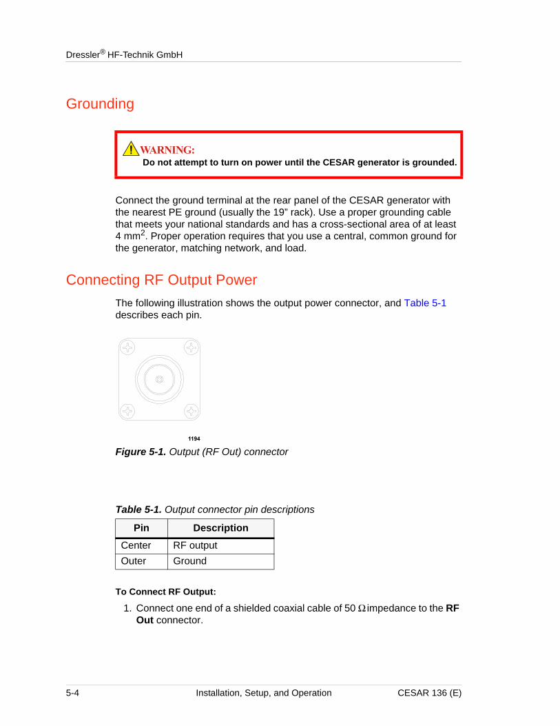
Dressler® HF-Technik GmbH
Grounding
Connect the ground terminal at the rear panel of the CESAR generator with the nearest PE ground (usually the 19” rack). Use a proper grounding cable that meets your national standards and has a cross-sectional area of at least 4 mm2. Proper operation requires that you use a central, common ground for the generator, matching network, and load.
Connecting RF Output PowerThe following illustration shows the output power connector, and Table 5-1 describes each pin.
Figure 5-1. Output (RF Out) connector
To Connect RF Output:
1. Connect one end of a shielded coaxial cable of 50 Ω impedance to the RF Out connector.
Do not attempt to turn on power until the CESAR generator is grounded.
Table 5-1. Output connector pin descriptions
Pin DescriptionCenter RF outputOuter Ground
5-4 Installation, Setup, and Operation CESAR 136 (E)
CESAR™ 136 Generator
2. Connect the other end of the cable to the input of the load or matching network (labeled RF Generator on the Variomatch).
Note: For information on optimum cable length, contact customer service (for contact information, see “Customer Support” on page 6-14).
Connecting Communication InterfacesThe communication interfaces that you use will depend on how you want to communicate with the CESAR generator and which interface options you have. The unit provides several communication interface options that allow you to control the unit remotely: a 25-pin User Port or a 15-pin User Port and an RS-232 Host port, a PROFIBUS Host port, or an Ethernet Host port.
To determine which communication interfaces your unit has, see “Understanding Model 136 Options” on page 1-2.
Note: Even if you are not using the User Port port for communication, some User Port circuits must be satisfied to operate the CESAR generator. For more information, see “CESAR Generator User Port Options” on page 4-11.
To Connect the Communication Interfaces:
Make each interface connection. For specific information on the interface connections, including pin descriptions and communication protocols, see Chapter 4, “Communication Interfaces.”
Connecting the CESAR Generator to a System Interlock Loop
In order for the CESAR generator to operate, you must satisfy the interlock requirements. How to satisfy the interlock depends on the type of User Port you have.
Note: To determine which communication interfaces you have, see “Understanding Model 136 Options” on page 1-2.
SATISFYING THE INTERLOCK WITH A 25-PIN USER PORT
If you have a 25-pin User Port, see the instructions for “Satisfying Minimal 25-Pin User Port Requirements” on page 4-12.
CESAR 136 (E) Installation, Setup, and Operation 5-5
Dressler® HF-Technik GmbH
SATISFYING THE INTERLOCK WITH A 15-PIN USER PORT
Units with a 15-pin User Port also have an Interlock interface that allows you to connect the CESAR generator into a larger system interlock loop. For specific information on the Interlock interface, including pin descriptions, see “Satisfying the Interlock” on page 4-30.
To Connect the System Interlock:
Connect the 9-pin Interlock connector to the associated socket at the rear panel.
Connecting a Matchbox (Optional)If you want the CESAR generator to control a matching network and/or to read the DC self-bias voltage, you must connect a matching unit. The CESAR generator is compatible with a Dressler Variomatch or a matching network with the same control functions and electronic topology. For specific information on the Matching interface, including pin descriptions, see “Matching Interface” on page 4-9.
To Connect a Matchbox:
1. Connect one end of an “RC” control cable to the CESAR generator’s Matching interface.
2. Connect the other end of the cable to the matching network’s interface (labeled Interface on the Variomatch).
Improper connection to any existing external matching units to the CESAR RF unit could result in product or property damage.
5-6 Installation, Setup, and Operation CESAR 136 (E)
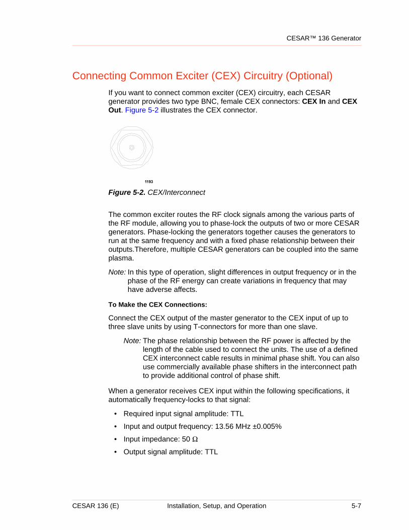
CESAR™ 136 Generator
Connecting Common Exciter (CEX) Circuitry (Optional)If you want to connect common exciter (CEX) circuitry, each CESAR generator provides two type BNC, female CEX connectors: CEX In and CEX Out. Figure 5-2 illustrates the CEX connector.
Figure 5-2. CEX/Interconnect
The common exciter routes the RF clock signals among the various parts of the RF module, allowing you to phase-lock the outputs of two or more CESAR generators. Phase-locking the generators together causes the generators to run at the same frequency and with a fixed phase relationship between their outputs.Therefore, multiple CESAR generators can be coupled into the same plasma.
Note: In this type of operation, slight differences in output frequency or in the phase of the RF energy can create variations in frequency that may have adverse affects.
To Make the CEX Connections:
Connect the CEX output of the master generator to the CEX input of up to three slave units by using T-connectors for more than one slave.
Note: The phase relationship between the RF power is affected by the length of the cable used to connect the units. The use of a defined CEX interconnect cable results in minimal phase shift. You can also use commercially available phase shifters in the interconnect path to provide additional control of phase shift.
When a generator receives CEX input within the following specifications, it automatically frequency-locks to that signal:
• Required input signal amplitude: TTL
• Input and output frequency: 13.56 MHz ±0.005%
• Input impedance: 50 Ω
• Output signal amplitude: TTL
CESAR 136 (E) Installation, Setup, and Operation 5-7
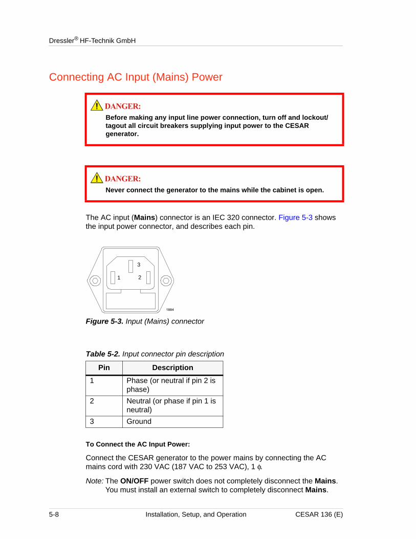
Dressler® HF-Technik GmbH
Connecting AC Input (Mains) Power
The AC input (Mains) connector is an IEC 320 connector. Figure 5-3 shows the input power connector, and describes each pin.
Figure 5-3. Input (Mains) connector
To Connect the AC Input Power:
Connect the CESAR generator to the power mains by connecting the AC mains cord with 230 VAC (187 VAC to 253 VAC), 1 φ.
Note: The ON/OFF power switch does not completely disconnect the Mains. You must install an external switch to completely disconnect Mains.
Before making any input line power connection, turn off and lockout/tagout all circuit breakers supplying input power to the CESAR generator.
Never connect the generator to the mains while the cabinet is open.
Table 5-2. Input connector pin description
Pin Description1 Phase (or neutral if pin 2 is
phase)2 Neutral (or phase if pin 1 is
neutral)3 Ground
1 2
3
5-8 Installation, Setup, and Operation CESAR 136 (E)
CESAR™ 136 Generator
Connecting and Setting Ethernet (Modbus/TCP) Communication
Your CESAR Generator may include an Ethernet port, which allows you to create a Modbus/TCP network connection to the unit.
Note: To determine which product option you have, see “Understanding Model 136 Options” on page 1-2.
This section provides information on connecting for Ethernet communication and setting the IP configuration for your unit, which will allow you to connect to the unit through your network. For more information, see also “Host Port—Ethernet (Modbus/TCP)” on page 4-57 and “Connecting to an Ethernet-Enabled Unit With a Web Browser” on page 5-49.
CONNECTING FOR ETHERNET COMMUNICATION
To connect for Ethernet communication, connect the CESAR generator Ethernet port to a network connection using a standard, straight-through network cable. The CESAR generator does not include this cable.
SETTING THE IP CONFIGURATION FOR ETHERNET COMMUNICATION
The CESAR generator is shipped with the following default IP configuration:
• IP address: 192.168.111.111
• Netmask address: 255.255.255.0
• Gateway address: not set
Before using the system, you must reset the IP configuration to settings appropriate for your network.
Selecting an Appropriate IP Configuration
Selecting an appropriate IP configuration for your network can be difficult. Setting an address that already exists may cause serious network problems. Consult your network administrator for appropriate IP configuration settings.
Once you have identified an appropriate IP address, you can use the ping command in the Windows® Command Prompt to make sure that the network address is not currently in use. If the address is free at the moment you send the ping command, the result will be “Request timed out.” For more information on using the ping command and the Command Prompt, see the Windows Help (available under the Windows Start button).
CESAR 136 (E) Installation, Setup, and Operation 5-9
Dressler® HF-Technik GmbH
Changing the IP Configuration
The CESAR generator is designed for use in a BootP environment (that is, a BootP server is running on the LAN), which will automatically set the unit IP configuration. However, you can also reset the IP configuration settings in a non-BootP environment. The following procedures provide instructions for both situations.
To Change the IP Configuration With BootP:
1. Configure your BootP server to recognize the CESAR generator MAC address (located on a sticker on the back of the unit, close to the Ethernet connector).
2. In the BootP server configuration, set an IP address for the CESAR generator that is appropriate for your network, and assign the MAC address of the CESAR generator to this IP address. (Consult your network administrator to identify appropriate IP address settings.)
3. Connect the CESAR generator to the network (this network should be routed to the BootP server) using a standard, straight-through network cable.
4. Power the CESAR generator on. In approximately 30 seconds, the CESAR generator will be visible to the BootP server and consequently your network (at the address specified in step 2).
To Change the IP Configuration Without BootP:
If you are using the Modbus CESAR generator in a non-BootP environment, you need to change the IP configuration through the BootP server utility that was included (on a CD-ROM) with the unit. For more information on using this software, see the Online Help system available when you launch the software.
FIRST-TIME OPERATIONBefore proceeding with first-time operation, be sure you have satisfied the installation requirements and completed the installation procedures described in “Installation Requirements” on page 5-2 and “Installing the CESAR Generator” on page 5-3.
There are several ways in which you can operate CESAR generator. Refer to the section that describes how you intend to operate the generator:
• “Operating the CESAR Generator for the First Time With the User Port” on page 5-11
• “Operating the CESAR Generator for the First Time With Host Port” on page 5-13
5-10 Installation, Setup, and Operation CESAR 136 (E)
CESAR™ 136 Generator
• “Operating the CESAR Generator for the First Time Using the Front Panel” on page 5-14
Operating the CESAR Generator for the First Time With the User Port
There are two User Port options (for specific User Port information, see “CESAR Generator User Port Options” on page 4-11). This section describes operating procedures for both User Port options. If you have a 25-pin User Port, proceed to the next section; if you have a 15-pin User Port, see “To Operate the CESAR Generator for the First Time Using the 15-pin User Port:” on page 5-12.
Note: To determine which User Port option you have, see “CESAR 136 (E) options” on page 1-2.
To Operate the CESAR Generator for the First Time Using the 25-pin User Port:
1. If the generator is not connected to a system interlock loop, verify that there is external contact closure between pins 10 and 23 (INTERLOCK LOOP). See Table 4-2 on page 4-14 for more information.
2. Power on the system by turning the front panel ON/OFF switch clockwise to a vertical position.
The initial front panel screen will display the CESAR generator model name, the operating frequency, the maximum RF power, and the software version. After five seconds, the display will change to a standard operation screen.
3. Listen to ensure the fans are rotating.
4. On the front panel, set the Control by setting to User Port (see “Changing the Device Configuration Settings” on page 5-40.
5. Verify that you have selected the desired power regulation:
4See pin 6 for “RF Forward power/ DC Bias regulation” on page 4-17.
4See pin 8 for “RF forward/load power regulation” on page 4-19.
For a description of regulation settings, see “Setting Regulation Mode” on page 5-15.
6. Apply the appropriate voltage to pin 5 (SET POINT). See Table 4-2 on page 4-14 for more information.
7. Apply the appropriate voltage to pin 4 (RF PWR ON). See Table 4-2 on page 4-14 for more information.
8. Check the load. If your load is a plasma:
a. Is the plasma lit? If not, you may have a faulty connector or too little input power (see “Troubleshooting Guide” on page 6-2).
CESAR 136 (E) Installation, Setup, and Operation 5-11
Dressler® HF-Technik GmbH
b. Is the plasma stable (that is, is the plasma producing a constant glow)? If not, see “Troubleshooting Guide” on page 6-2.
9. If you have a matching network connected, did the capacitors begin to move? If not, see “Matching Network Troubleshooting” on page 6-2.
10. Vary the chamber conditions according to your process requirements, and verify that the CESAR generator can cover the required load impedance range.
Congratulations, you have successfully installed and operated the CESAR generator.
To Operate the CESAR Generator for the First Time Using the 15-pin User Port:
1. If the generator is not connected to a system interlock loop, verify that there is external contact closure between Interlock pins 1 and 2 (see Table 4-3 on page 4-31).
2. Power on the system by turning the front panel ON/OFF switch clockwise to a vertical position.
The initial front panel screen will display the CESAR generator model name, the operating frequency, the maximum RF power, and the software version. After five seconds, the display will change to a standard operation screen.
3. Listen to ensure the fans are rotating.
4. On the front panel, set the Control by setting to User Port (see “Changing the Device Configuration Settings” on page 5-40.
5. Verify that you have selected the desired power regulation mode:
4See User Port pins 1 and 2 in Table 4-4 on page 4-32 and Table 4-5 on page 4-36.
6. Apply the appropriate voltage to User Port pin 12 (RF POWER SET POINT). See Table 4-4 on page 4-32 for more information.
7. Apply the appropriate voltage to User Port pin 10 (RF PWR ON). See Table 4-4 on page 4-32 for more information.
8. Check the load. If your load is a plasma:
a. Is the plasma lit? If not, you may have a faulty connector or too little input power (see “Troubleshooting Guide” on page 6-2).
b. Is the plasma stable (that is, is the plasma producing a constant glow)? If not, see “Troubleshooting Guide” on page 6-2.
9. If you have a matching network connected, did the capacitors begin to move? If not, see “Matching Network Troubleshooting” on page 6-2.
10. Vary the chamber conditions according to your process requirements, and verify that the CESAR generator can cover the required load impedance range.
5-12 Installation, Setup, and Operation CESAR 136 (E)
CESAR™ 136 Generator
Congratulations, you have successfully installed and operated the CESAR generator.
Operating the CESAR Generator for the First Time With Host Port
There are three Host port options (for specific Host port information, see “CESAR Generator Host Port Options” on page 4-43). This section describes operating procedures for all Host port options.
Note: To determine which option you have, see “CESAR 136 (E) options” on page 1-2
To Operate the CESAR Generator for the First Time Using the Host Port:
1. If the generator is not connected to a system interlock loop, verify that the User Port interlock signal is satisfied.
4 If you have a 25-pin User Port, verify that there is external contact closure between pins 10 and 23 (INTERLOCK LOOP). See Table 4-2 on page 4-14 for more information.
4 If you have a 15-pin User Port, verify that there is external contact closure between Interlock pins 1 and 2 (see Table 4-3 on page 4-31).
2. Power on the system by turning the front panel ON/OFF switch clockwise to a vertical position. The initial front panel screen will display the CESAR generator model name, the operating frequency, the maximum RF power, and the software version. After five seconds, the display will change to a standard operation screen.
3. Listen to ensure the fans are rotating.
4. Set the Host control mode by sending active control mode command 14
42 = Host (serial) control
5. Select the desired regulation mode by sending regulation mode command 3 (for a description of regulation mode settings, see “Setting Regulation Mode” on page 5-15).
46 = Forward power (Pforward) regulation
47 = Load power (Preal) regulation
48 = External power (DC Bias) regulation
Note: You cannot change power regulation mode while RF power is on.
6. Send set point command 8 to set the set point.
7. Send RF on command 2 to turn on RF power.
8. Check the load. If your load is a plasma:
a. Is the plasma lit? If not, you may have a faulty connector or too little
CESAR 136 (E) Installation, Setup, and Operation 5-13
Dressler® HF-Technik GmbH
input power (see “Troubleshooting Guide” on page 6-2).
b. Is the plasma stable (that is, is the plasma producing a constant glow)? If not, see “Troubleshooting Guide” on page 6-2.
9. If you have a matching network connected, did the capacitors begin to move? If not, see “Matching Network Troubleshooting” on page 6-2.
10. Vary the chamber conditions according to your process requirements, and verify that the CESAR generator can cover the required load impedance range.
Congratulations, you have successfully installed and operated the CESAR generator.
Operating the CESAR Generator for the First Time Using the Front Panel
You can operate the CESAR generator using full front panel control or remote control with partial front panel control. This section describes full front panel control operation. For partial control (Remote Control Override), see “Setting Remote Control Override” on page 5-37.
To Operate the CESAR Generator for the First Time Using the Front Panel:
1. Ensure that the User Port interlock signal is satisfied.
4 If you have a 25-pin User Port, verify that there is external contact closure between pins 10 and 23 (INTERLOCK LOOP). See Table 4-2 on page 4-14 for more information.
4 If you have a 15-pin User Port, verify that there is external contact closure between Interlock pins 1 and 2 (see Table 4-3 on page 4-31).
2. Power on the system by turning the front panel ON/OFF switch clockwise to a vertical position. The initial front panel screen will display the CESAR generator model name, the operating frequency, the maximum RF power, and the software version. After five seconds, the display will change to a standard operation screen.
3. Listen to ensure the fans are rotating.
4. Press the RF POWER ON key on the front panel.
5. Use the RF POWER rotary dial knob to increase the RF power to a desired level.
6. Check the load. If the load is a plasma:
a. Is the plasma lit? If not, you may have a faulty connector or too little input power (see “Troubleshooting Guide” on page 6-2).
b. Is the plasma stable (that is, is the plasma producing a constant glow)? If not, see “Troubleshooting Guide” on page 6-2.
5-14 Installation, Setup, and Operation CESAR 136 (E)
CESAR™ 136 Generator
7. If you have a matching network connected and you are using automatic tune control (see “Setting Automatic Tune Control” on page 5-22 for more information).
4Did the capacitors begin to move? If not, see “Matching Network Troubleshooting” on page 6-2.
8. Vary the chamber conditions according to your process requirements, and verify that the CESAR generator can cover the required load impedance range.
Congratulations, you have successfully installed and operated the CESAR generator.
NORMAL OPERATIONThe following sections provide information on basic operating procedures and settings for normal operation. For information on more specialized operation settings and procedures, see “Understanding Additional Operating Functions” on page 5-44.
Setting Regulation ModeThe CESAR generator is designed to regulate power into a broad range of output impedances. The unit can operate in the following:
• Forward power regulation (Pforward)
In forward power regulation mode, the CESAR Generator regulates RF power with constant forward power.
• Load power regulation, or delivered power regulation (Preal)
In load power regulation mode, the CESAR Generator regulates RF power with constant load (real) power.
• External power regulation (DC Bias)
In external power regulation mode, the CESAR Generator regulates RF power at a constant DC self bias voltage in the chamber. The RF output power can be limited to protect your plasma chamber against high RF power. This limitation is useful if there is no self bias voltage in the beginning of the process.
The regulation mode setting is retained in nonvolatile memory.
DETERMINING THE REGULATION MODE SETTING
The following procedures explain how to determine the regulation mode using either the Host port or the front panel.
CESAR 136 (E) Installation, Setup, and Operation 5-15
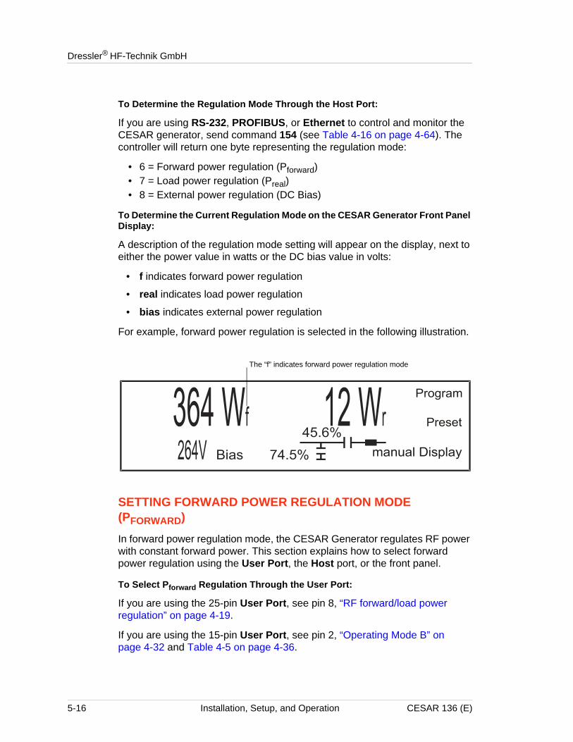
Dressler® HF-Technik GmbH
To Determine the Regulation Mode Through the Host Port:
If you are using RS-232, PROFIBUS, or Ethernet to control and monitor the CESAR generator, send command 154 (see Table 4-16 on page 4-64). The controller will return one byte representing the regulation mode:
• 6 = Forward power regulation (Pforward)• 7 = Load power regulation (Preal)• 8 = External power regulation (DC Bias)
To Determine the Current Regulation Mode on the CESAR Generator Front Panel Display:
A description of the regulation mode setting will appear on the display, next to either the power value in watts or the DC bias value in volts:
• f indicates forward power regulation
• real indicates load power regulation
• bias indicates external power regulation
For example, forward power regulation is selected in the following illustration.
SETTING FORWARD POWER REGULATION MODE (PFORWARD)
In forward power regulation mode, the CESAR Generator regulates RF power with constant forward power. This section explains how to select forward power regulation using the User Port, the Host port, or the front panel.
To Select Pforward Regulation Through the User Port:
If you are using the 25-pin User Port, see pin 8, “RF forward/load power regulation” on page 4-19.
If you are using the 15-pin User Port, see pin 2, “Operating Mode B” on page 4-32 and Table 4-5 on page 4-36.
The “f” indicates forward power regulation mode
5-16 Installation, Setup, and Operation CESAR 136 (E)
CESAR™ 136 Generator
To Select Forward Power Regulation Through the Host Port:
If you are using RS-232, PROFIBUS, or Ethernet to control and monitor the CESAR generator:
1. Select forward power regulation mode:Send one data byte for command 3 (see Table 4-16 on page 4-64).
46 = Forward power regulation2. Specify the output set point level for the regulation mode:
Send two data bytes, least significant byte first, for command 8 representing the set point level in watts (see Table 4-16 on page 4-64).
To Select Forward Power Regulation Using the CESAR Generator Front Panel:
Complete the following steps to select Pforward regulation using the front panel:
1. Press the Program soft key. Control Settings appears on the display.
2. Press Change.
3. Press Control Pforward.
4. Select the desired power set point between 0 W and 600 W using the RF POWER dial knob. Press the Increm Auto soft key to toggle between dynamic increments (Auto) and several fixed increments.
5. Press Ok to confirm.
6. Press Exit.7. Press Execute.
The operating screen will then display the forward power in watts, the reflected power in watts, and the Program and Display soft keys.
SETTING LOAD POWER REGULATION MODE (PREAL)
In load power regulation mode, the CESAR Generator regulates RF power with constant load (real) power. This section explains how to select load power regulation using the User Port, the Host port, or the front panel.
To Select Load Power Regulation Through the User Port:
If you are using the 25-pin User Port, see pin 8, “RF forward/load power regulation” on page 4-19.
If you are using the 15-pin User Port, see pin 2, “Operating Mode B” on page 4-32 and Table 4-5 on page 4-36.
To Select Load Power Regulation through the Host Port:
If you are using RS-232, PROFIBUS, or Ethernet to control and monitor the CESAR generator:
CESAR 136 (E) Installation, Setup, and Operation 5-17
Dressler® HF-Technik GmbH
1. Select load power regulation mode:Send one data byte for command 3 (see Table 4-16 on page 4-64).
47 = Load power regulation2. Specify the output set point level for the regulation mode:
Send two data bytes, least significant byte first, for command 8 representing the set point level in watts (see Table 4-16 on page 4-64).
To Select Load Power Regulation Using the CESAR Generator Front Panel:
Complete the following steps to select Preal regulation mode using the front panel:
1. Press the Program soft key. Control Settings appears on the display.
2. Press Change.
3. Press Control Preal.
4. Select the desired power set point between 0 W and 600 W using the RF POWER rotary dial knob. Press the Increm Auto soft key to toggle between dynamic increments (Auto) and several fixed increments.
5. Press Ok to confirm.
6. Press Exit.7. Press Execute.
The operating screen will then display the load power in watts, the reflected power in watts, and the Program and Display soft keys.
SETTING EXTERNAL POWER REGULATION MODE (DC BIAS)
In external power regulation mode, the CESAR Generator regulates RF power at a constant DC self bias voltage in the plasma chamber. The RF output power can be limited to protect your plasma chamber against high RF power. This limitation is useful if there is no self bias voltage in the beginning of the process.
This section explains how to select external power regulation using the User Port, the Host port, or the front panel.
To Select External Power Regulation Through the User Port:
If you are using the 25-pin User Port, see pin 8, “RF forward/load power regulation” on page 4-19.
If you are using the 15-pin User Port, see pin 2, “Operating Mode B” on page 4-32 and Table 4-5 on page 4-36.
5-18 Installation, Setup, and Operation CESAR 136 (E)
CESAR™ 136 Generator
To Select External Power Regulation Through the Host Port:
If you are using RS-232, PROFIBUS, or Ethernet to control and monitor the CESAR generator:
1. Select external power regulation:Send one data byte for command 3 (see Table 4-16 on page 4-64).
48 = External power regulation (DC Bias)2. Specify the maximum forward power that can be delivered:
Send two data bytes, least significant byte first, for command 4 representing the maximum forward power in watts (see Table 4-16 on page 4-64).
3. Specify the output set point level for the regulation mode:Send two data bytes, least significant byte first, for command 8 representing the set point level in watts (see Table 4-16 on page 4-64).
Selecting DC Bias Regulation Using the CESAR Generator Front Panel:
Complete the following steps to select DC Bias regulation mode using the front panel:
1. Press the Program soft key. Control Settings appears on the display.
2. Press Change.
3. Press Control DC Bias.
4. Set a DC Bias value using the RF POWER dial knob. Press the Increm Auto soft key to toggle between dynamic increments (Auto) and several fixed increments.
4The value can be between 0 V and 4000 V
Note: 4000 V is the default value. To change the default settings, see “To Change the Default Device Configuration Settings Using the CESAR Generator Front Panel:” on page 5-41
5. Press Ok to confirm.
6. Set a Pforward maximum value between 5% of nominal power and 600 W using a combination of the Increm Auto and the RF POWER dial knob.
7. Press Ok to confirm.
8. Press Exit.9. Press Execute.
The operating screen will then display DC Bias in volts, the maximum forward power in watts, and the Program and Display soft keys.
CESAR 136 (E) Installation, Setup, and Operation 5-19
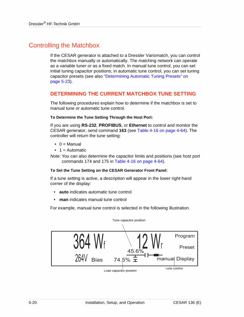
Dressler® HF-Technik GmbH
Controlling the MatchboxIf the CESAR generator is attached to a Dressler Variomatch, you can control the matchbox manually or automatically. The matching network can operate as a variable tuner or as a fixed match. In manual tune control, you can set initial tuning capacitor positions; in automatic tune control, you can set tuning capacitor presets (see also “Determining Automatic Tuning Presets” on page 5-23).
DETERMINING THE CURRENT MATCHBOX TUNE SETTING
The following procedures explain how to determine if the matchbox is set to manual tune or automatic tune control.
To Determine the Tune Setting Through the Host Port:
If you are using RS-232, PROFIBUS, or Ethernet to control and monitor the CESAR generator, send command 163 (see Table 4-16 on page 4-64). The controller will return the tune setting:
• 0 = Manual• 1 = Automatic
Note: You can also determine the capacitor limits and positions (see host port commands 174 and 175 in Table 4-16 on page 4-64).
To Set the Tune Setting on the CESAR Generator Front Panel:
If a tune setting is active, a description will appear in the lower right-hand corner of the display:
• auto indicates automatic tune control
• man indicates manual tune control
For example, manual tune control is selected in the following illustration.
Tune capacitor position
Load capacitor positionTune control
5-20 Installation, Setup, and Operation CESAR 136 (E)
CESAR™ 136 Generator
SETTING MANUAL TUNE CONTROL
In manual tune control, the automatic tuning feature is disabled, and capacitor position is controlled only through the generator front panel.
This section explains how to select manual tune control using the Host port or front panel.
To Select Manual Tune Through the Host Port:
If you are using RS-232, PROFIBUS, or Ethernet to control the matchbox manually:
1. Send one data byte for command 13 (see Table 4-16 on page 4-64):
40 = Manual2. To manually change the tune positions, see “To Adjust the Tune and Load
Capacitors Using the CESAR Generator Front Panel:” on page 5-44.
To Set the Initial C Tune and C Load Positions in Manual Mode With the CESAR Generator Front Panel:
Complete the following steps to set initial C Tune and C Load positions in Manual mode using the CESAR generator front panel:
1. Press the Program soft key.
2. Press Next until you see Match Settings on the display.
3. Press Change.
4. Press manual.5. Select the initial C Tune position using the RF POWER rotary dial knob.
4You may select values between 4% and 96%.
6. Press Ok to confirm.
7. Select the initial C Load position using the RF POWER rotary dial knob.
4You may select values between 4% and 96%.
8. Press Ok to confirm.
9. Press the Exit soft key.
10. Press the Execute soft key.
The tune and load capacitors will move to the initial tune positions, and the associated position values will begin to flash on the display, indicating that the capacitors are moving.
To manually change the tune positions from these initial positions, see “To Adjust the Tune and Load Capacitors Using the CESAR Generator Front Panel:” on page 5-44.
CESAR 136 (E) Installation, Setup, and Operation 5-21
Dressler® HF-Technik GmbH
SETTING AUTOMATIC TUNE CONTROL
Dressler recommends automatic tune control for standard matchbox operation. In automatic tune control, the matchbox automatically adjusts the capacitor positions to minimize reflected power. When a matchbox is attached and automatic tuning is set, the matchbox automatically adjusts the capacitor positions to minimize reflected power. The CESAR generator can set the matchbox to preset positions to find the optimum capacitor positions and ensure the shortest possible plasma ignition time. You can program the preset positions using either the front panel display or commands from the Host port.
Selecting Automatic Tune Through the Host Port:
If you are using RS-232, PROFIBUS, or Ethernet to control the matchbox automatically:
4Select the tune control setting:Send one data byte for command 13 (see Table 4-16 on page 4-64):
41 = Automatic1. Set the load capacitor position:
Send two data bytes for command 112 (see Table 4-16 on page 4-64).
2. Set the tune capacitor position:Send two data bytes for command 122 (see Table 4-16 on page 4-64).
3. To manually change the tune positions from these initial positions, see “To Adjust the Tune and Load Capacitors Using the CESAR Generator Front Panel:” on page 5-44.
See also “Determining Automatic Tuning Presets” on page 5-23 and “Controlling a Variomatch Unit Attached to the Generator” on page 5-43.
To Set the Initial C Tune and C Load Positions in Automatic Mode With the CESAR Generator Front Panel:
Complete the following steps to set the initial capacitor positions in automatic tune mode using the CESAR generator front panel:
1. Press the Program soft key.
2. Press Next until you see Match Settings on the display.
3. Press Change.
4. Press auto.
5. Select the desired C Tune position using the RF POWER rotary dial knob.
4You may select values between 40 and 960.
6. Press Ok to confirm.
7. Select the desired C Load position using the RF POWER rotary dial knob.
4You may select values between 40 and 960.
5-22 Installation, Setup, and Operation CESAR 136 (E)
CESAR™ 136 Generator
8. Press Ok to confirm.
9. Press the Exit soft key.
10. Press the Execute soft key.
The capacitors will move to the programmed positions, and the associated position values will begin to flash on the display, indicating that the capacitors are moving.
See also “Determining Automatic Tuning Presets” on page 5-23 and “Controlling a Variomatch Unit Attached to the Generator” on page 5-43.
Determining Automatic Tuning Presets
The automatic tuning preset values establish the initial positions for both the tune (C Tune) and load (C Load) capacitors before RF power turns on. This feature is useful for different process recipes. You can change the preset values to meet your specific process needs. Appropriate preset values vary widely from application to application, depending on operating variables such as the type of application gas, the amount of pressure in the chamber, and the configuration of the chamber.
To Determine Appropriate Preset Positions:
1. In an experimental chamber, turn on RF power at the expected power level.
2. Allow the CESAR generator to tune in manual tune control.
4 If the plasma ignites, use the Matching controls on the front panel to adjust the tuning parameters only slightly and find the optimum positions.
4 If the plasma fails to ignite, experiment to find a position where the plasma will ignite; then make small adjustments from that point to find the optimum positions.
CESAR 136 (E) Installation, Setup, and Operation 5-23
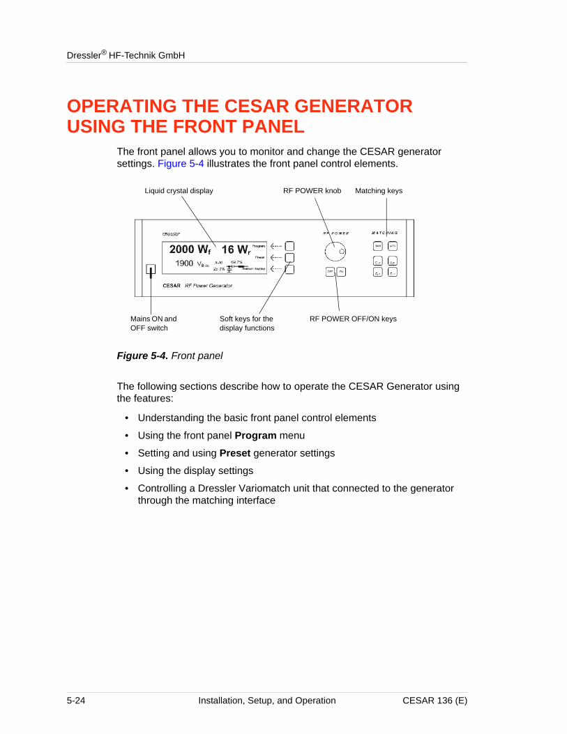
Dressler® HF-Technik GmbH
OPERATING THE CESAR GENERATOR USING THE FRONT PANEL
The front panel allows you to monitor and change the CESAR generator settings. Figure 5-4 illustrates the front panel control elements.
Figure 5-4. Front panel
The following sections describe how to operate the CESAR Generator using the features:
• Understanding the basic front panel control elements
• Using the front panel Program menu
• Setting and using Preset generator settings
• Using the display settings
• Controlling a Dressler Variomatch unit that connected to the generator through the matching interface
Liquid crystal display
Mains ON and OFF switch
RF POWER knob Matching keys
Soft keys for the display functions
RF POWER OFF/ON keys
5-24 Installation, Setup, and Operation CESAR 136 (E)
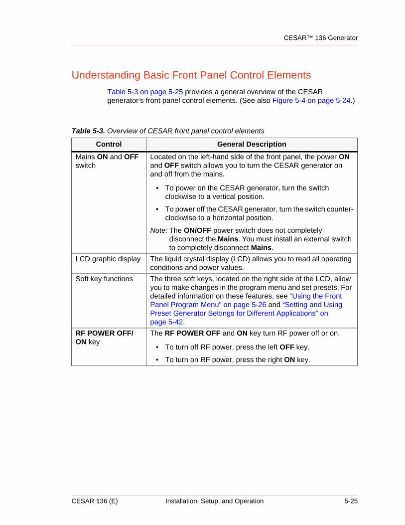
CESAR™ 136 Generator
Understanding Basic Front Panel Control ElementsTable 5-3 on page 5-25 provides a general overview of the CESAR generator’s front panel control elements. (See also Figure 5-4 on page 5-24.)
Table 5-3. Overview of CESAR front panel control elements
Control General DescriptionMains ON and OFF switch
Located on the left-hand side of the front panel, the power ON and OFF switch allows you to turn the CESAR generator on and off from the mains.
• To power on the CESAR generator, turn the switch clockwise to a vertical position.
• To power off the CESAR generator, turn the switch counter-clockwise to a horizontal position.
Note: The ON/OFF power switch does not completely disconnect the Mains. You must install an external switch to completely disconnect Mains.
LCD graphic display The liquid crystal display (LCD) allows you to read all operating conditions and power values.
Soft key functions The three soft keys, located on the right side of the LCD, allow you to make changes in the program menu and set presets. For detailed information on these features, see “Using the Front Panel Program Menu” on page 5-26 and “Setting and Using Preset Generator Settings for Different Applications” on page 5-42.
RF POWER OFF/ON key
The RF POWER OFF and ON key turn RF power off or on.
• To turn off RF power, press the left OFF key.
• To turn on RF power, press the right ON key.
CESAR 136 (E) Installation, Setup, and Operation 5-25
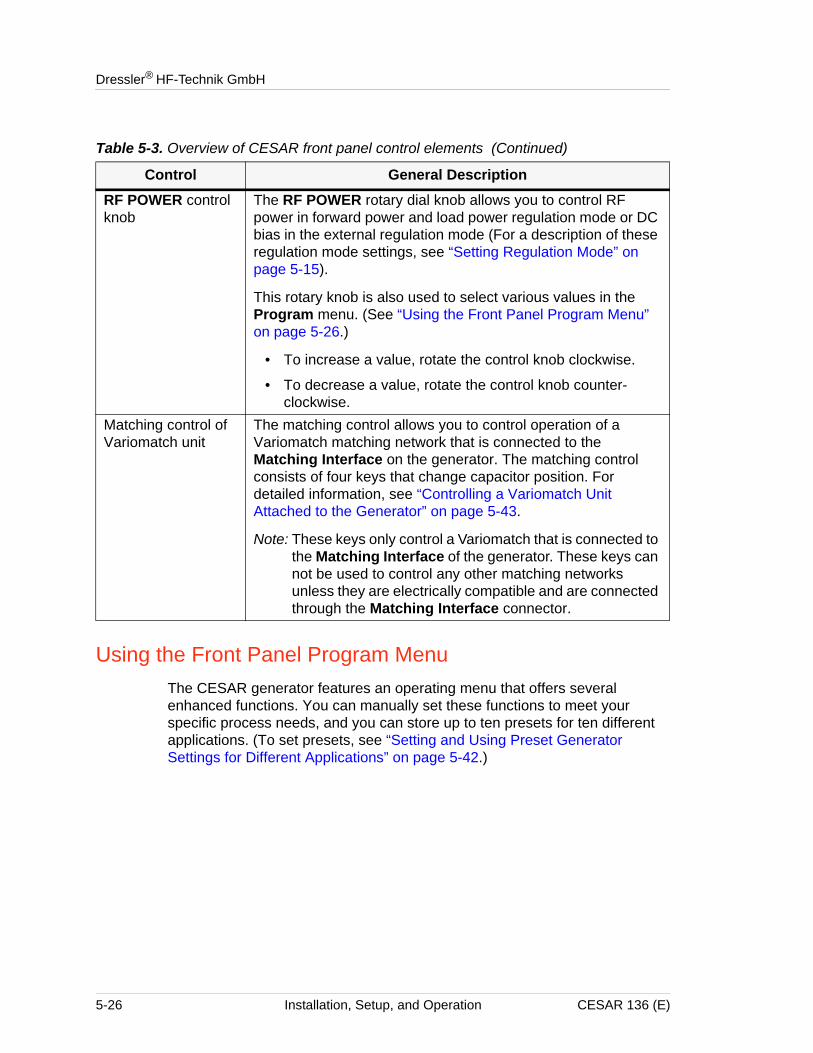
Dressler® HF-Technik GmbH
Using the Front Panel Program MenuThe CESAR generator features an operating menu that offers several enhanced functions. You can manually set these functions to meet your specific process needs, and you can store up to ten presets for ten different applications. (To set presets, see “Setting and Using Preset Generator Settings for Different Applications” on page 5-42.)
RF POWER control knob
The RF POWER rotary dial knob allows you to control RF power in forward power and load power regulation mode or DC bias in the external regulation mode (For a description of these regulation mode settings, see “Setting Regulation Mode” on page 5-15).
This rotary knob is also used to select various values in the Program menu. (See “Using the Front Panel Program Menu” on page 5-26.)
• To increase a value, rotate the control knob clockwise.
• To decrease a value, rotate the control knob counter-clockwise.
Matching control of Variomatch unit
The matching control allows you to control operation of a Variomatch matching network that is connected to the Matching Interface on the generator. The matching control consists of four keys that change capacitor position. For detailed information, see “Controlling a Variomatch Unit Attached to the Generator” on page 5-43.
Note: These keys only control a Variomatch that is connected to the Matching Interface of the generator. These keys can not be used to control any other matching networks unless they are electrically compatible and are connected through the Matching Interface connector.
Table 5-3. Overview of CESAR front panel control elements (Continued)
Control General Description
5-26 Installation, Setup, and Operation CESAR 136 (E)
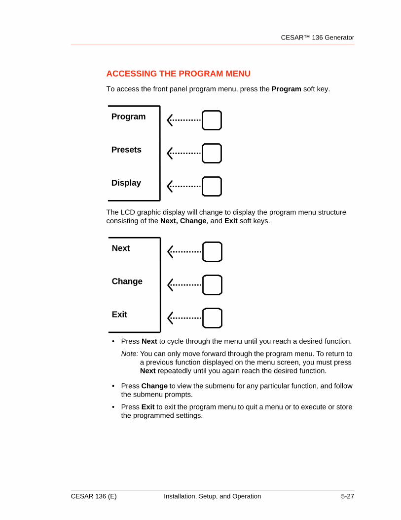
CESAR™ 136 Generator
ACCESSING THE PROGRAM MENU
To access the front panel program menu, press the Program soft key.
The LCD graphic display will change to display the program menu structure consisting of the Next, Change, and Exit soft keys.
• Press Next to cycle through the menu until you reach a desired function.
Note: You can only move forward through the program menu. To return to a previous function displayed on the menu screen, you must press Next repeatedly until you again reach the desired function.
• Press Change to view the submenu for any particular function, and follow the submenu prompts.
• Press Exit to exit the program menu to quit a menu or to execute or store the programmed settings.
Display
Presets
Program
Exit
Change
Next
CESAR 136 (E) Installation, Setup, and Operation 5-27
Dressler® HF-Technik GmbH
ENTERING VALUES IN THE PROGRAM MENU
You may change a variety of parameters in the program menu by using a combination of the soft keys and the RF POWER rotary knob. Use the soft keys to make menu selections, and use the RF POWER rotary knob to set specific values. Then press the appropriate soft key to save that value.
Note: You can only move forward through the program menu. To return to a previous function displayed on the menu screen, you must press Next repeatedly until you again reach the desired function.
For more specific menu information, see “Front Panel Program Menu Tree” on page 5-29
5-28 Installation, Setup, and Operation CESAR 136 (E)
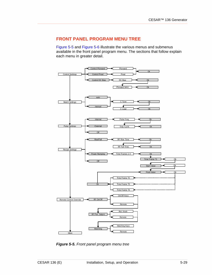
CESAR™ 136 Generator
FRONT PANEL PROGRAM MENU TREE
Figure 5-5 and Figure 5-6 illustrate the various menus and submenus available in the front panel program menu. The sections that follow explain each menu in greater detail.
Figure 5-5. Front panel program menu tree
Control Settings
Match Settings
Pulse Settings
Recipe Settings
Control Pforward
Control Preal
auto
manual
C Tune
C Load
Internal
External
Pulse Freq.
Duty Cycle
Rise/Fall RF Rise Time
RF Fall Time
Time Frames 1-4 Ok
Time Frame T2
Time Frame T3
Time Frame T4
Start Value
Final Value
Time Frame T1
Pforward
Off
More
Control DC Bias DC Bias
Preal
Power Ramping
Off
Remote Control Override RF On/Off
RF Pwr. Setpnt
Matching
On/Off Keys
Remote
Ok
Pforward MAX
Ok
Ok
Ok
Ok
Ok
Ok
Ok
Ok
Rot. Knob
Remote
Matching Keys
Remote
Ok
Ok
Ok
Ok
CESAR 136 (E) Installation, Setup, and Operation 5-29
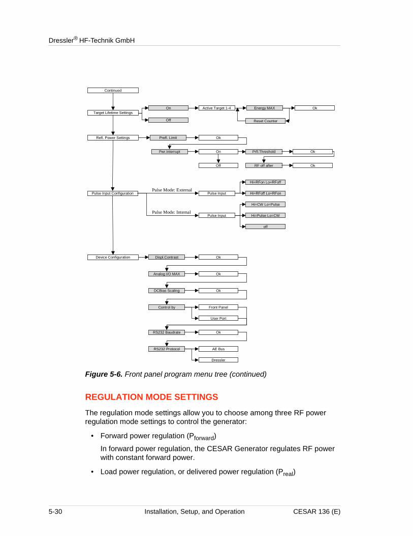
Dressler® HF-Technik GmbH
Figure 5-6. Front panel program menu tree (continued)
REGULATION MODE SETTINGS
The regulation mode settings allow you to choose among three RF power regulation mode settings to control the generator:
• Forward power regulation (Pforward)
In forward power regulation, the CESAR Generator regulates RF power with constant forward power.
• Load power regulation, or delivered power regulation (Preal)
Pulse Input
Hi=RFon Lo=RFoff
Hi=RFoff Lo=RFon
Refl. Power Settings
Pulse Input Configuration
Prfl.Threshold
RF off after Ok
On
Off
Pwr.Interrupt
Device Configuration Displ.Contrast Ok
Analog I/O MAX
DCBias Scaling
Ok
Active Target 1-4 Energy MAX OkOn
Off Reset Counter
Prefl. Limit Ok
Ok
Pulse Input
Hi=CW Lo=Pulse
Hi=Pulse Lo=CW
off
Pulse Mode: External
Pulse Mode: Internal
Ok
RS232 Baudrate Ok
RS232 Protocol AE Bus
Dressler
Control by Front Panel
User Port
Continued
Target Lifetime Settings
5-30 Installation, Setup, and Operation CESAR 136 (E)
CESAR™ 136 Generator
In load power regulation, the CESAR Generator regulates RF power with constant load (real) power.
• External power regulation (DC Bias)
In external power regulation, the CESAR Generator regulates RF power at a constant DC self bias voltage in the chamber. The RF output power can be limited to protect your plasma chamber against high RF power. This limitation is useful if there is no self bias voltage in the beginning of the process.
To Select a Regulation Mode Using the CESAR Generator Front Panel:
1. Press the Program soft key.
2. Press Next until you see Control Settings on the display.
3. Press Change.
4. Press the soft key for the desired regulation mode: Control Pforward, Control Preal, or Control DC Bias.
5. For Pforward or Preal regulation mode, set the desired power set point between 0 W and 600 W using a combination of the Increm Auto key and the RF POWER dial knob.
6. For DC Bias control, set a DC Bias value using a combination of the Increm Auto key and the RF POWER dial knob.
4The value can be between 0 V and 4000 V
Note: 4000 V is the default value. To change the default settings, see “To Change the Default Device Configuration Settings Using the CESAR Generator Front Panel:” on page 5-41
7. Press Ok to confirm.
8. For DC Bias control, set a Pforward maximum value between 60 W and 600 W using a combination of the Increm Auto and the RF POWER dial knob.
9. Press Ok to confirm.
10. Press Exit.11. Press Execute.
The operating screen will change to display the new control settings and values.
MATCH SETTINGS
If your RF power delivery system includes a Dressler Variomatch connected to the matching interface of the CESAR generator, you can use this function to control the matching network. This function enables you to set initial tuning
CESAR 136 (E) Installation, Setup, and Operation 5-31
Dressler® HF-Technik GmbH
capacitor positions (in manual tune control) or to set tuning capacitor presets (in automatic tune control). For information on the matching interface, see “Matching Interface” on page 4-9.
Note: These controls only work with a Variomatch that is connected to the matching interface of the generator. This function can not be used to control any other matching networks unless they are electrically compatible and are connected through the Matching Interface connector.
You may choose between:
• Manual tune
In manual tune control, the automatic tuning feature is disabled, and you can manually set the tune and load capacitor positions of the Variomatch unit.
• Automatic tune
In automatic tune control, the Variomatch unit sets presets to automatically adjust the capacitor positions and minimize reflected power. See “Setting Automatic Tune Control” on page 5-22 for additional information.
To Select Tuning Control Using the CESAR Generator Front Panel:
1. Press the Program soft key.
2. Press Next until you see Match Settings on the display.
3. Press Change.
4. Press auto for automatic tune control; press man for manual tune control.
5. Select the desired C Tune position using the RF POWER rotary dial knob.
4You may select values between 40 and 960.
6. Select Ok to confirm.
7. Select the desired C Load position using the RF POWER rotary dial knob.
4You may select values between 40 and 960.
8. Press Ok to confirm.
9. Press the Exit soft key.
10. Press the Execute soft key.
The capacitors will move to the tune positions, and the associated position values will begin to flash on the display. To manually change the capacitor positions from these initial positions, see “To Adjust the Tune and Load Capacitors Using the CESAR Generator Front Panel:” on page 5-44.
5-32 Installation, Setup, and Operation CESAR 136 (E)
CESAR™ 136 Generator
SETTING THE PULSE FUNCTION
The CESAR generator’s pulse function allows you to switch on the RF power (at a given set point) and switch it off with the pulse frequency. You may to select between:
• Internal pulsing
Internal pulsing modifies the pulse repetition frequency (PRF). The waveform is always a rectangle; the power is given by the set point.
• External pulsing
The pulsing of the Cesar generator will work according to the pulse input configuration settings. See “Changing the Pulse Input Configuration Settings” on page 5-39.
To Select Internal or External Pulsing Using the CESAR Generator Front Panel:
1. Press the Program soft key.
2. Press Next until you see Pulse Settings on the display.
3. Press Change.
4. Press Internal for internal pulsing; press External for external pulsing.
5. For internal pulsing:
a. Select the desired Pulse Freq. value between 1 Hz and 30 kHz or less (depending on the factory setting for pulsing) using a combination of the Increm Auto button and the RF POWER rotary dial knob.
b. Press Ok to confirm.
c. Select a duty cycle value between 1% to 99% using the RF POWER rotary dial knob.
Note: The duty cycle is a function of the pulse repetition frequency (PRF), and the wide range of 1% to 99% only exists at low pulse frequencies. The higher the PRF, the lower the possible duty cycle range. For example, at 30 kHz PRF, the duty cycle is limited to 40% to 60%.
6. Press Ok to confirm.
7. Press the Exit soft key.
8. Press the Execute soft key.
The operating screen will change to display the pulsing status.
To Turn Off Pulsing Using the CESAR Generator Front Panel:
1. Press the Program soft key.
2. Press Next until you see Pulse Settings on the display.
CESAR 136 (E) Installation, Setup, and Operation 5-33
Dressler® HF-Technik GmbH
3. Press Change.
4. Press Off to turn off the pulsing feature.
5. Press the Exit soft key.
6. Press the Execute soft key.
RECIPE SETTINGS
This feature enables you to create a power profile that may consist of up to four time frames. You can choose to program one of the two recipe settings using the CESAR Generator front panel:
1. Rise/fall time
This feature allows gradual, well-controlled development of the rising and falling edge of the RF power envelope, which differs significantly from common RF power functionality with its fast and uncontrolled rise time. You can program your “critical plasma system” to strike smoothly with a well-controlled rising edge of the RF power.
2. Power ramping
Power ramping allows you to determine the shape of a power ramp within a specified time frame. There are four programmable time frames.
To Create the Rise/fall Recipe Using the CESAR Generator Front Panel:
1. Press the Program soft key.
2. Press Next until you see Recipe Settings on the display.
3. Press Change.
4. Press Rise/Fall.5. Set the RF rise time between 0.1 s and 60 s using a combination of the
Increm Auto key and the RF POWER rotary knob.
6. Press Ok to confirm.
7. Set the RF Fall time between 0.1 s and 60 s using a combination of the Increm Auto key and the RF POWER rotary knob.
8. Press Ok to confirm.
To Create the Power Ramping Recipe Using CESAR Generator Front Panel:
1. Press the Program soft key.
2. Press Next until you see Recipe Settings on the display.
3. Press Change.
4. Press Power Ramping.
a. Select the number of time frames (1 to 4) you want to use in your recipe
5-34 Installation, Setup, and Operation CESAR 136 (E)
CESAR™ 136 Generator
using the RF POWER rotary knob.
b. Press Ok to confirm.
c. Set a time for T1 (the recipe’s first power ramp) between 0.1 s and 60 minutes using a combination of the Increm Auto key and the RF POWER rotary knob.
d. Press Ok to confirm.
e. Set a Start Power value for T1 between 0 W and 600 W using a combination of the Increm Auto key and the RF POWER rotary knob.
f. Set a Final Power value for T1 between 0 W and 600 W using a combination of the Increm Auto key and the RF POWER rotary knob.
g. Press Ok to confirm.
h. Set a time for T2 (the recipe’s second power ramp) between 0.1 and 60 minutes using a combination of the Increm Auto key and the RF POWER rotary knob.
i. Press Ok to confirm.
j. The Start Power value will display as the final value of T1; set a Final Value for T2 between 0 W and 600 W using a combination of the Increm Auto key and the RF POWER rotary knob.
k. Repeat the last three steps to set time frames for T3 and T4 (the recipe’s third and fourth power ramps).
5. Press Ok to confirm.
6. Press the Exit soft key.
7. Press the Execute soft key.
The operating screen will change to display the current recipe status. See the following illustration for an example.
CESAR 136 (E) Installation, Setup, and Operation 5-35
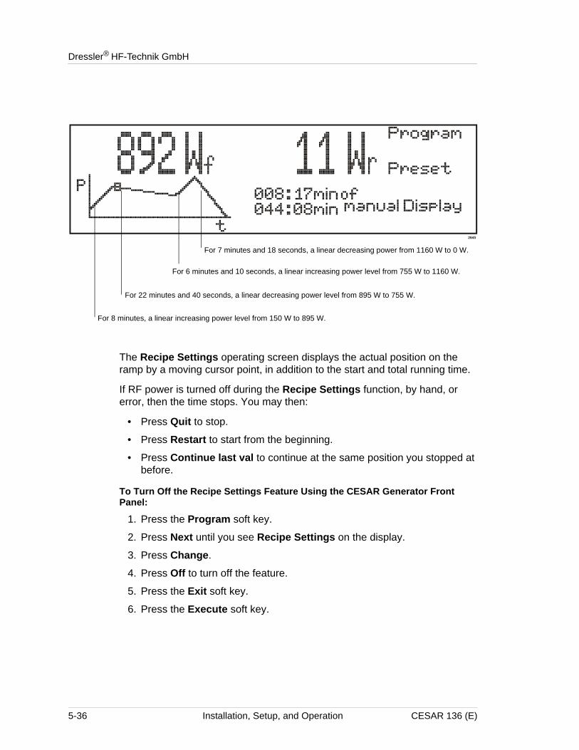
Dressler® HF-Technik GmbH
The Recipe Settings operating screen displays the actual position on the ramp by a moving cursor point, in addition to the start and total running time.
If RF power is turned off during the Recipe Settings function, by hand, or error, then the time stops. You may then:
• Press Quit to stop.
• Press Restart to start from the beginning.
• Press Continue last val to continue at the same position you stopped at before.
To Turn Off the Recipe Settings Feature Using the CESAR Generator Front Panel:
1. Press the Program soft key.
2. Press Next until you see Recipe Settings on the display.
3. Press Change.
4. Press Off to turn off the feature.
5. Press the Exit soft key.
6. Press the Execute soft key.
For 8 minutes, a linear increasing power level from 150 W to 895 W.
For 6 minutes and 10 seconds, a linear increasing power level from 755 W to 1160 W.
For 7 minutes and 18 seconds, a linear decreasing power from 1160 W to 0 W.
For 22 minutes and 40 seconds, a linear decreasing power level from 895 W to 755 W.
5-36 Installation, Setup, and Operation CESAR 136 (E)
CESAR™ 136 Generator
SETTING REMOTE CONTROL OVERRIDE
Remote Control Override allows you operate the CESAR generator using a combination of front panel control (local) and analog or digital (remote) control. You may control the generator remotely yet retain the following front panel (local) functions:
• Rotary dial knob controlSee “RF POWER control knob” on page 5-26 for detailed information on this front panel control.
• RF POWER Off/On keysSee “RF POWER OFF/ON key” on page 5-25 for detailed information on these front panel control keys.
• Matching controlsSee “Matching control of Variomatch unit” on page 5-26 and “Controlling a Variomatch Unit Attached to the Generator” on page 5-43 for detailed information on these front panel control keys and how to use them.
Note: Normally, when using remote control, all front panel controls are disabled.
To Select Remote Control Override Using the CESAR Generator Front Panel:
1. Press the Program soft key.
2. Press Next until you see Remote Control Override on the display.
3. Press Change.
4. To use the RF ON/OFF front panel controls, press On/Off Keys; to leave these controls as remote functions only, press Remote.
5. To use the Rot. Knob front panel control, press Rot.Knob; to leave this control as a remote function, press Remote.
6. To use the Matching front panel controls, press Matching Keys; to leave these controls as remote functions only, press Remote.
7. Press the Exit soft key.
8. Press the Execute soft key.
To Disable Remote Control Override Using the CESAR Generator Front Panel:
When you disable Remote Control Override control, the generator will default to remote control if it is connected to an analog User Port; otherwise, if there is no analog User Port present, it will default to front panel (local) control.
1. Press the Program soft key.
2. Press Next until you see Remote Control Override on the display.
3. Press Change.
CESAR 136 (E) Installation, Setup, and Operation 5-37
Dressler® HF-Technik GmbH
4. Select Remote for each of the options.
5. Press the Exit soft key.
6. Press the Execute soft key.
SETTING TARGET LIFETIME PARAMETERS
In the Target Lifetime menu, you may program up to four target lifetime settings to integrate power and time. The CESAR generator will display a warning when the meter reading reaches the value of Energy Max.
To Set a Target Lifetime Using the CESAR Generator Front Panel:
1. Press the Program soft key.
2. Press Next until you see Target Lifetime Settings on the display.
3. Press Change.
4. Press On to activate the lifetime counter.
5. Select an Active Target (1 to 4) using the RF POWER rotary knob.
6. Select the Energy MAX (between 0.01 kWh and 21600 kWh) using a combination of the Auto Increm. button and the RF POWER rotary knob.
7. Press Ok to confirm.
8. Press the Exit soft key.
9. Press the Execute soft key.
To Turn Off the Target Lifetime Feature Using the CESAR Generator Front Panel:
1. Press the Program soft key.
2. Press Next until you see Target Lifetime Settings on the display.
3. Press Change.
4. Press Off.5. Press the Exit soft key.
6. Press the Execute soft key.
To Reset a Target Lifetime Using the CESAR Generator Front Panel:
Note: Reset starts the counter to zero.
1. Press the Program soft key.
2. Press Next until you see Target Lifetime Settings on the display.
3. Press Change.
4. When Active Target appears, press On.
5. When Energy MAX appears, press Ok.
5-38 Installation, Setup, and Operation CESAR 136 (E)
CESAR™ 136 Generator
6. Press Reset to reset the lifetime counter.
7. Press Ok when the reset message appears.
8. Press Ok.
9. Press the Exit soft key.
10. Press the Execute soft key.
REFLECTED POWER SETTINGS
The CESAR generator can tolerate continuous reflected power; however, it allows you to set a value at which the forward power will fold back when the reflected power reaches a certain limit for a specified period of time. The Reflected Power Settings menu allows you to create a reaction profile to shut off RF power when the reflected power reaches this limit.
To Set a Reflected Power Reaction Profile Using the CESAR Generator Front Panel:
1. Press the Program soft key.
2. Press Next until you see Reflected Power Settings on the display.
3. Press Change.
4. Set a Prefl. Threshold between 20 W and 200 W using the RF POWER rotary knob.
5. Press Ok.
6. If you want the generator to shut off when it reaches this limit for a specified period of time, press On. Otherwise, press Off.a. If you select On:
4 Set the desired max refl. value (between 12 W and 180 W) using the RF POWER rotary dial knob.
4Set the desired RF Off After value (between 1 µs and 3 m 20 s) using the RF POWER rotary dial knob.
4Press Ok to confirm.
7. Press the Exit soft key.
8. Press the Execute soft key.
CHANGING THE PULSE INPUT CONFIGURATION SETTINGS
Before changing the pulse input configuration settings, you must first turn on the pulsing function. For more information, see “To Select Internal or External Pulsing Using the CESAR Generator Front Panel:” on page 5-33.
The configuration settings allow you to program the “polarity” of the CESAR generator's pulse input function.
CESAR 136 (E) Installation, Setup, and Operation 5-39
Dressler® HF-Technik GmbH
To Set the Pulsing Input Parameters Using the CESAR Generator Front Panel:
1. Press the Program soft key.
2. Press Next until you see Pulse Input Configuration on the display.
3. Press Change.
4. Select the desired “polarity” of the pulse input:
a. If the pulse function is set to external pulsing, choose either:
4Hi=RFonLow=RFoff
This setting enables standard external pulsing.
4Hi=RFoffLow=RF on
This setting enables inverse external pulsing.
b. If the pulse function is set to internal pulsing, choose from:
4Hi=CWLow=Pulse
This setting switches between internal pulsing and continuous power with the pulse input at a high state.
4Hi=PulseLow=CW
This setting switches between internal pulsing and continuous power with the pulse input at a low state.
4OffThis setting disables the pulse input. Normal internal pulsing is used.
5. Press the Exit soft key.
6. Press the Execute soft key.
CHANGING THE DEVICE CONFIGURATION SETTINGS
The Device Configuration feature allows you to change the factory default settings and customize the CESAR generator to meet your specific needs. You can change the following parameters:
• Display contrast
Display contrast allows you to adjust the contrast (brightness) of the LCD graphic display.
• Analog I/O range
5-40 Installation, Setup, and Operation CESAR 136 (E)
CESAR™ 136 Generator
The analog interface level is factory set to the most common level range of 0 V to 10 V. However, you may reprogram this value by changing the maximum voltage of possible analog interface levels from 2 V to 10 V. These levels apply to all analog inputs and outputs on the user port.
• DC Bias Scaling
You may set the maximum DC bias in volts from 0 V to 4000 V (in increments of 1, 10, 100, 10000, and Auto). 4000 V is the default value.
• Control by
This feature lets you choose between Front Panel control and User Port control in which the generator will try to detect the User Port.
• RS232 baud rate
If your CESAR generator has an RS-232 port, this function allows you to select the desired baud rate: 9600, 19200, 38400, 56000, or 115200.
Note: To determine if you have an RS-232 port, see “Understanding Model 136 Options” on page 1-2.
• RS232 protocol
If your CESAR generator has an RS232 port, the RS-232 protocol is factory-set to AE Bus, and most CESAR generators will use the default AE Bus protocol (see “AE Bus Protocol” on page 4-46). However, a previous protocol (Dressler) is available for compatibility.
Note: To determine if you have an RS-232 port, see “Understanding Model 136 Options” on page 1-2.
To Change the Default Device Configuration Settings Using the CESAR Generator Front Panel:
1. Press the Program soft key.
2. Press Next until you see Device Configuration on the display.
3. Press Change.
4. Select the desired Displ. Contrast value using the RF POWER rotary dial knob.
5. Press Ok to confirm.
6. Press the desired Analog I/O Max level using the RF POWER rotary dial knob.
4You may select values between 2 V and 10 V.
7. Press Ok to confirm.
8. Select the desired DC Bias Scaling using the RF POWER rotary dial knob.
CESAR 136 (E) Installation, Setup, and Operation 5-41
Dressler® HF-Technik GmbH
4You may select values between 0 V and 4000 V using a combination of the Increm Auto key and the RF POWER rotary dial.
9. Press Ok to confirm.
10. Press the desired Control by setting:
4Front Panel defaults to front panel control.
4User Port defaults to User Port control.
11. If your CESAR generator has an RS-232 port, select the desired RS232 Baud Rate value using the RF POWER rotary dial knob.
12. Press Ok to confirm.
13. If your CESAR generator has an RS-232 port, select the desired RS232 Protocol.
4AE BUS is the standard protocol for CESAR generators.
4Dressler is available for compatibility only.14. Press Ok to confirm.
15. Press the Exit soft key.
16. Press the Execute soft key.
Setting and Using Preset Generator Settings for Different Applications
You can set the various front panel functions to meet your specific process needs, and you can store up to five presets (1 through 5) for five different applications. The presets store all settings in the program menu except pulse input configuration and device configuration. Preset 0 is reserved for factory settings and can be accessed read-only.
To Store a Preset Using the CESAR Generator Front Panel:
1. Set all of the desired parameters using the front panel program menu (see “Using the Front Panel Program Menu” on page 5-26).
2. After you have made the appropriate program menu selections, you will have the option to Execute, Store Preset, or Quit.
3. Press Store Preset. The settings for this particular preset will flash on the front panel.
To Erase a Preset Using the CESAR Generator Front Panel:
1. Go to the preset number you wish to erase. (When you select a number, the settings for each particular preset will flash on the front panel).
2. Press Quit.
5-42 Installation, Setup, and Operation CESAR 136 (E)
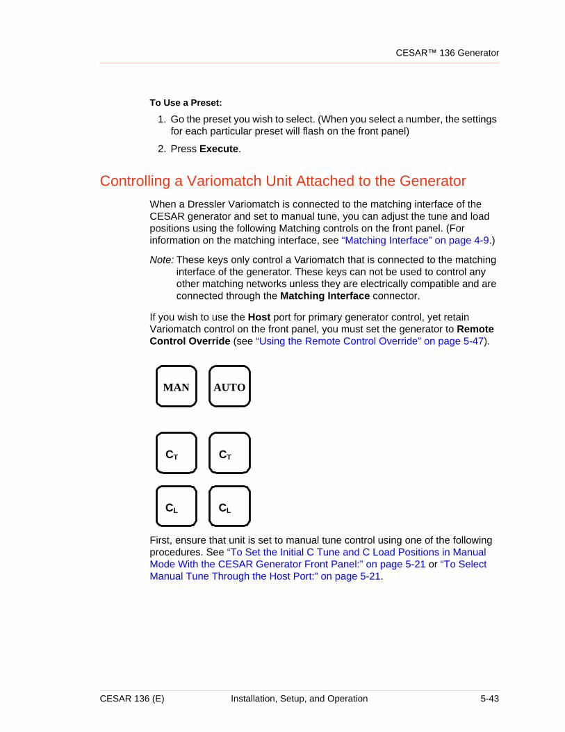
CESAR™ 136 Generator
To Use a Preset:
1. Go the preset you wish to select. (When you select a number, the settings for each particular preset will flash on the front panel)
2. Press Execute.
Controlling a Variomatch Unit Attached to the GeneratorWhen a Dressler Variomatch is connected to the matching interface of the CESAR generator and set to manual tune, you can adjust the tune and load positions using the following Matching controls on the front panel. (For information on the matching interface, see “Matching Interface” on page 4-9.)
Note: These keys only control a Variomatch that is connected to the matching interface of the generator. These keys can not be used to control any other matching networks unless they are electrically compatible and are connected through the Matching Interface connector.
If you wish to use the Host port for primary generator control, yet retain Variomatch control on the front panel, you must set the generator to Remote Control Override (see “Using the Remote Control Override” on page 5-47).
First, ensure that unit is set to manual tune control using one of the following procedures. See “To Set the Initial C Tune and C Load Positions in Manual Mode With the CESAR Generator Front Panel:” on page 5-21 or “To Select Manual Tune Through the Host Port:” on page 5-21.
AUTOMAN
CT CT
CL CL
CESAR 136 (E) Installation, Setup, and Operation 5-43
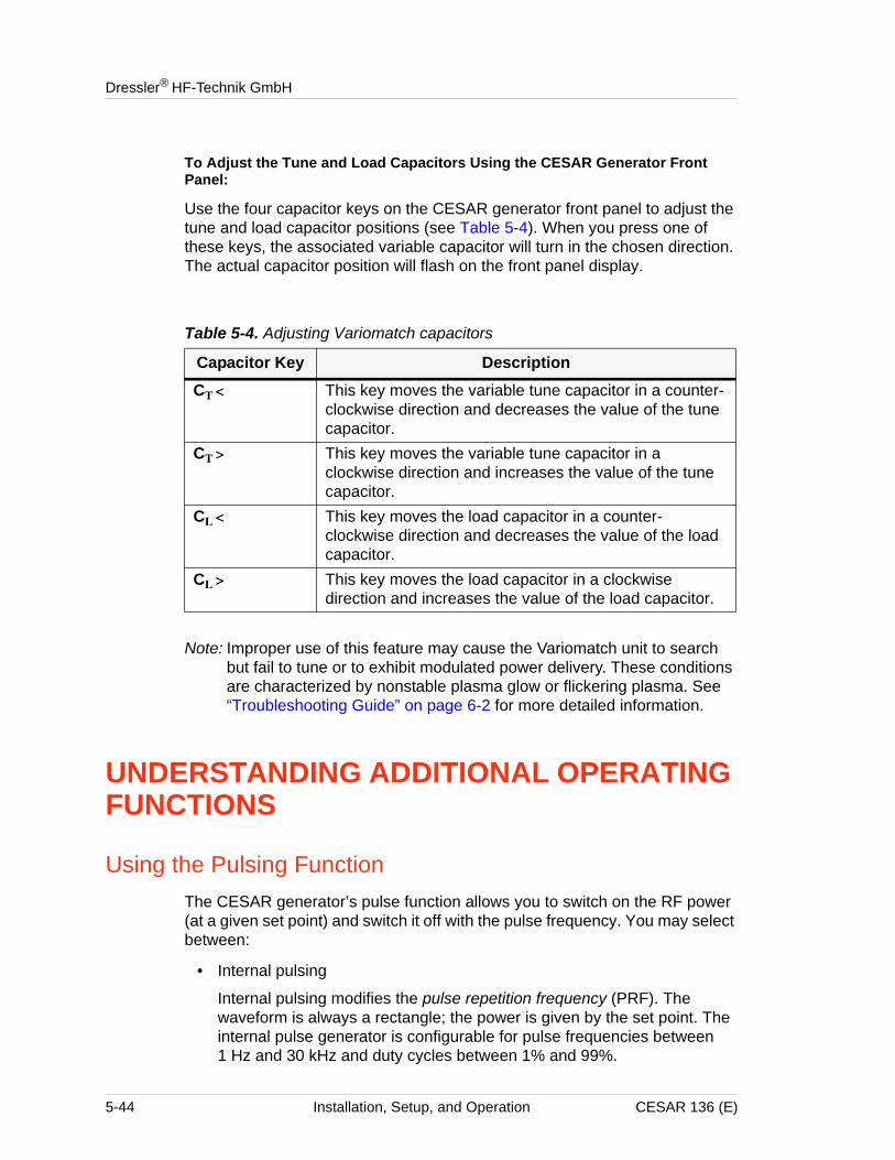
Dressler® HF-Technik GmbH
To Adjust the Tune and Load Capacitors Using the CESAR Generator Front Panel:
Use the four capacitor keys on the CESAR generator front panel to adjust the tune and load capacitor positions (see Table 5-4). When you press one of these keys, the associated variable capacitor will turn in the chosen direction. The actual capacitor position will flash on the front panel display.
Note: Improper use of this feature may cause the Variomatch unit to search but fail to tune or to exhibit modulated power delivery. These conditions are characterized by nonstable plasma glow or flickering plasma. See “Troubleshooting Guide” on page 6-2 for more detailed information.
UNDERSTANDING ADDITIONAL OPERATING FUNCTIONS
Using the Pulsing FunctionThe CESAR generator’s pulse function allows you to switch on the RF power (at a given set point) and switch it off with the pulse frequency. You may select between:
• Internal pulsing
Internal pulsing modifies the pulse repetition frequency (PRF). The waveform is always a rectangle; the power is given by the set point. The internal pulse generator is configurable for pulse frequencies between 1 Hz and 30 kHz and duty cycles between 1% and 99%.
Table 5-4. Adjusting Variomatch capacitors
Capacitor Key DescriptionCT < This key moves the variable tune capacitor in a counter-
clockwise direction and decreases the value of the tune capacitor.
CT > This key moves the variable tune capacitor in a clockwise direction and increases the value of the tune capacitor.
CL < This key moves the load capacitor in a counter-clockwise direction and decreases the value of the load capacitor.
CL > This key moves the load capacitor in a clockwise direction and increases the value of the load capacitor.
5-44 Installation, Setup, and Operation CESAR 136 (E)
CESAR™ 136 Generator
• External pulsing
The pulsing of the Cesar generator will work according to the gating pulse signal applied to the analog User Port. The pulse-gating signal must be of a 5 V TTL/CMOS level.
To Select Internal or External Pulsing Through the Host Port:
If you are using RS-232, PROFIBUS, or Ethernet to control and monitor the CESAR generator:
1. Set the desired pulse setting: Send one data byte for command 27 (see Table 4-16 on page 4-64):
40 = Pulsing off
41 = Internal pulsing
42 = External pulsing
43 = External pulsing inverted
44 = Enable internal pulsing by external pulsing input2. Set the desired pulse frequency value:
Send three data bytes, least significant byte first, for command 93 representing the pulsing frequency in Hertz (see Table 4-16 on page 4-64).
3. Select a duty cycle value:Send two data bytes, least significant byte first, for command 96 representing the duty cycle as a percentage (seeTable 4-16 on page 4-64).
To Select Internal or External Pulsing Using the CESAR Generator Front Panel, see instructions on page 5-33.
Creating RecipesThis feature enables you to create a power profile that may provide up to four time frames. You can choose to program one of the two recipe settings using the CESAR generator front panel:
1. Rise/fall time recipe
This feature allows gradual, well-controlled development of the rising and falling edge of the RF power envelope, which differs significantly from common RF power functionality which has a fast and uncontrolled rise time. You can program your “critical plasma system” to strike smoothly with a well-controlled rising edge of the RF power.
4The rising edge of the RF envelope can be set to have a linear rise time of 0.1 seconds to 60 seconds. The time increment is 0.1 seconds.
4The falling edge of the RF envelope can be set to have a linear fall time of 0.1 seconds to 60 seconds. The time increment is 0.1 seconds.
CESAR 136 (E) Installation, Setup, and Operation 5-45
Dressler® HF-Technik GmbH
2. Power ramping recipe
The function mode allows you to determine the shape of a power ramp within a certain time frame. There are four programmable time frames. For each time frame, you may control the following parameters:
• Set the time duration of the presence of RF power from 0.1 second to 1440 minutes
• Set the start value of the RF power in watts• Set the end value of the RF power in watts
Creating Recipes Through the Host Port:
If you are using RS-232, PROFIBUS, or Ethernet to control and monitor the CESAR generator:
Note: For host port commands, see Table 4-16 on page 4-64.
1. Set the number of recipes:Send one data byte for command 19, representing the desired number of recipe steps.
2. Specify the ramp time for each given recipe using command 21:
a. Send one byte to select the step number 1 to 2
b. Send two bytes to set the ramp time value.
3. Specify the set point for each given recipe step using command 22:
a. Send one byte to select the recipe step number 1 to 2
b. Send two bytes to specify the set point value.
4. Set the run time for each given recipe using command 23:
a. Send one byte to select the recipe step number 1 to 2.
b. Send two bytes to set the run time in seconds.
5. Set the ramping rise time:Send two bytes, least significant byte first, for command 31, representing the ramping rise time in tenths of a second.
6. Set the ramping fall time:
a. Send two bytes, least significant byte first, for command 32, representing the ramping fall time in tenths of a second.
5-46 Installation, Setup, and Operation CESAR 136 (E)
CESAR™ 136 Generator
To Create Recipes Using the CESAR Generator Front Panel, see instructions on page 5-47.
Using the Remote Control OverrideRemote Control Override allows you operate a CESAR generator using a combination of front panel control (local) and analog or digital (remote) control. If the generator is connected to an analog User Port, you may control the generator remotely yet retain the following front panel (local) functions:
• Rotary dial knob controlSee “RF POWER control knob” on page 5-26 for detailed information on this front panel control.
• RF POWER Off/On keysSee “RF POWER OFF/ON key” on page 5-25 for detailed information on these front panel control keys.
• Matching controlsSee “Matching control of Variomatch unit” on page 5-26 and “Controlling a Variomatch Unit Attached to the Generator” on page 5-43 for detailed information on these front panel control keys and how to use them.
Note: Normally, when using remote control, all front panel controls are disabled.
To Select Remote Control Override Through the Host Port:
If you are using RS-232, PROFIBUS, or Ethernet to control and monitor the CESAR generator:
1. Send command 29 (see Table 4-16 on page 4-64).
To Select Remote Control Override Using the CESAR Generator Front Panel, see instructions on page 5-37.
Setting a Target LifetimeIn the Target Lifetime menu, you may program up to four target lifetime settings to integrate the product of power and time. The CESAR generator will display a warning when it reaches a specified target lifetime value in kilowatt-hours.
The lifetime of a target depends primarily on the energy dissipated by this target. Thus, the target lifetime counter is an energy meter that monitors time and the output power. For working with different targets you can set up and choose among four target lifetime counters. Only one may be active at a time.
CESAR 136 (E) Installation, Setup, and Operation 5-47
Dressler® HF-Technik GmbH
To Set a Target Lifetime Through the Host Port:
If you are using RS-232, PROFIBUS, or Ethernet to control and monitor the CESAR generator:
1. Specify the number of targets:Send one byte for command 11 (see Table 4-16 on page 4-64).
2. Set the target life with command 12 (see Table 4-16 on page 4-64).
a. Send one byte to select the target number (1 to 4).
b. Send the remaining bytes 2 through 5 to specify the target life in kilowatt hours.
Note: A decimal is implied (for example, 100 = 1 kWh).
To Set a Target Lifetime Using the CESAR Generator Front Panel, see instructions on page 5-38.
Changing Reflected Power SettingsNormally, a generator delivers continuous reflected power; however, the CESAR generator allows you to set a value at which the forward power will fold back when the reflected power reaches a certain limit for a specified period of time. The Reflected Power Settings menu allows you to create a “reaction profile” to shut off RF power when the reflected power reaches this limit.
To Set a Reflected Power Reaction Profile Through the Host Port:
If you are using RS-232, PROFIBUS, or Ethernet to control and monitor the CESAR generator, set the reflected power parameter using command 33 (see Table 4-16 on page 4-64).
1. Send one byte to set the time until RF is turned off in seconds.
2. Send the remaining bytes 2 and 3 to set the reflected power detection level in watts.
To Set a Reflected Power Reaction Profile Using the CESAR Generator Front Panel, see instructions on page 5-39.
5-48 Installation, Setup, and Operation CESAR 136 (E)
CESAR™ 136 Generator
CONNECTING TO AN ETHERNET-ENABLED UNIT WITH A WEB BROWSER
Your CESAR Generator may include an Ethernet port, which allows you to create a Modbus/TCP network connection between the unit and your local area network (LAN). This section provides information on connecting to an Ethernet-enabled unit with a web browser.
For more information on the Ethernet connection, see also “Host Port—Ethernet (Modbus/TCP)” on page 4-57 and “Connecting and Setting Ethernet (Modbus/TCP) Communication” on page 5-9.
To Connect to an Ethernet-enabled CESAR Generator With a Web Browser:
1. Open a standard Web browser program.
2. Type the CESAR generator’s IP address into the Web browser Address field.
If you have trouble connecting, ensure that:
• The CESAR generator is connected to the network through the Ethernet port. (see “Connecting and Setting Ethernet (Modbus/TCP) Communication” on page 5-9 for more information).
• The CESAR generator is receiving proper input power (for specifications, see Chapter 3, “Electrical Specifications”).
• You are typing in the correct IP address (see “Setting the IP Configuration for Ethernet Communication” on page 5-9 for information on the default IP address and on resetting the IP address).
• The BootP server found the CESAR generator’s MAC address (if you are using a BootP server to change the IP address).
If you continue to have trouble, refer to the troubleshooting section of the Online Help for the BootP utility software that came with the unit (on a CD-ROM) or contact Customer Support.
CESAR 136 (E) Installation, Setup, and Operation 5-49

Dressler® HF-Technik GmbH
5-50 Installation, Setup, and Operation CESAR 136 (E)
ChapterCESAR™ 136 Generator
Chapter
6
Troubleshooting and Customer SupportThis chapter contains basic troubleshooting information, as well as procedures for returning a unit for repair.
BEFORE CONTACTING CUSTOMER SUPPORT
Before contacting Customer Support, perform the following steps or procedures.
Checks With the Power Off1. Ensure that the power to the unit is off.
2. Check for visible damage to the unit, cables, and connectors.
3. Ensure that all unit connectors are installed correctly and fastened tightly.
4. Check to determine whether any system-related circuit breakers have been tripped.
5. Verify that the input power to the unit meets specifications.
6. Ensure ground connections are adequate and secure.
Checks With the Power On1. Check the unit’s input and remote power connections to ensure the proper
power is being supplied to the unit.
RISK OF DEATH OR BODILY INJURY. Disconnect and lockout/tagout all sources of input power before working on this unit or anything connected to it.
CESAR 136 (E) Troubleshooting and Customer Support 6-1
Dressler® HF-Technik GmbH
Troubleshooting GuideThe following questions may help solve troubleshooting problems.
GENERAL TROUBLESHOOTING
Use the following procedure to troubleshoot general problems.
1. Did you install the CESAR generator according to the installation instructions in this manual?
4 If yes, go to the next step.
4 If no, reinstall the CESAR generator as described in “Installing the CESAR Generator” on page 5-3.
2. Is the mains voltage within specifications?
4 If yes, go to the next step.
4 If unsure or no, see “Incorrect Input Voltage” on page 6-5.
3. Is the interlock satisfied?
4 If yes, go to the next step.
4 If unsure or no, see “Interlock Not Satisfied” on page 6-3.
4. Is the front panel display (LCD) lit?
4 If yes, go to the next step.
4 If no, see “Front Panel Display (LCD) Not Lit” on page 6-4.
5. Check the front panel display for any fault (EXX) or warning (WXX) messages.
4 If there is no warning or error message on the display, go to the next step.
4 If there is an error or warning message on the display, see “Checking for and Resolving Errors and Warnings” on page 6-7.
6. Does the CESAR generator communicate with the host computer?
4 If yes, go to the next step.
4 If no, see “Communication Problems” on page 6-4.
7. For any other general problems, contact Customer Support (see “Customer Support” on page 6-14).
MATCHING NETWORK TROUBLESHOOTING
Use the following procedure to troubleshoot potential problems with the matching network.
6-2 Troubleshooting and Customer Support CESAR 136 (E)
CESAR™ 136 Generator
1. Did you install the matching network according to the instructions in the manual?
4 If yes, go to the next step.
4 If unsure or no, check installation or reinstall according to the manual that came with the matching network.
2. Did you verify that the impedance range of the matching network is appropriate to the load?
4 If yes, go to the next step.
4 If unsure or no, see “Improper Impedance Range” on page 6-5.
3. Did you properly establish the RF connections between the generator and the matching network as well as between the matching network and the load?
4 If yes, go to the next step.
4 If unsure or no, see “Improper RF Connection or Cabling” on page 6-5.
4. Did you establish proper common grounding for the generator, matching network, and load?
4 If yes, go to the next step.
4 If unsure or no, see “Improper Grounding” on page 6-6.
5. Did you establish the correct interface connection for remote control of the matching network?
4 If yes, but you are still having trouble, refer to the troubleshooting section of the matching network manual.
4 If unsure or no, see “Improper Interface Connection” on page 6-6.
6. If these steps have not resolved the problem, contact Customer Support (see “Customer Support” on page 6-14).
Interlock Not SatisfiedYou must satisfy the interlock connection, even if you do not connect the CESAR generator into a larger system interlock loop.
• To create hardware interlocks using the 25-pin User Port, see pins 10 and 23 in Table 4-2 on page 4-14.
• If you have a 15-pin User Port, ensure external contact closure between the Interlock pins 1 and 2 (see Table 4-3 on page 4-31).
Note: To determine which option you have see “Understanding Model 136 Options” on page 1-2.
CESAR 136 (E) Troubleshooting and Customer Support 6-3
Dressler® HF-Technik GmbH
Front Panel Display (LCD) Not LitThe front panel display should operate as soon as the front panel ON/OFF switch is turned on. Verify that the:
1. Front panel ON/OFF switch is in the ON position.
2. Input line voltage is 230 VAC (187 VAC to 253 VAC), 1 φ.
Communication ProblemsSeveral factors can cause communication problems:
• Poor grounding
Ensure that the communication cable shield is properly grounded. Ensure that the generator and the matching network are properly grounded according to the instructions in “Grounding” on page 5-4 and the installation section of the matching network manual.
• Improper cabling
Ensure that each of the communication cables matches the specifications listed in the associated sections of Chapter 4, “Communication Interfaces.”
• Incorrect baud rate (RS-232 Host port only)—
Ensure that the baud rate used by the host computer and the baud rate set in the CESAR generator are the same (see “RS-232 Transmission Parameters” on page 4-45).
• Incorrect or corrupt data packet
Verify that the data packet has been set up correctly (see “AE Bus Protocol” on page 4-46).
• Commands transferring too fast
Ensure the commands are sent to the CESAR generator at a rate less than 1 command every 50 milliseconds (20 commands per second) if you are not using the recommended handshaking protocol described in “Creating an Ideal Communications Transaction” on page 4-49.
Capacitor FailureThe CESAR generator is compatible with a Dressler Variomatch or a matching network with the same control functions and electronic topology. Several factors could cause the Variomatch capacitors to fail:
6-4 Troubleshooting and Customer Support CESAR 136 (E)
CESAR™ 136 Generator
• No or incorrect power or input voltage
• The unit set for incorrect tuning control
• Incorrect parameters set for the unit
Incorrect Input VoltageEnsure that the input voltage to the unit is within specifications (see “Electrical Specifications” on page 3-4).
Ensure that the input connector is connected to the correct pins, see “Installing the CESAR Generator” on page 5-3).
Once you have verified that you have the correct input voltage and connection, disconnect the input voltage and reconnect it. The capacitors should initialize, creating a high frequency for approximately 5 seconds and then stop.
Improper Impedance RangeA variety of problems can occur if the specifications of the connected matching network do not correspond to basic application parameters such as impedance, current, voltage, phase angle, forward power, and reflected power. These problems can include:’
• Difficulty igniting plasma
• Difficulty achieving expected minimum reflected power with manual or automatic tuning by the matching network
• Arcing inside the matching network
You can change the impedance range of the Variomatch by changing the Variomatch tap settings. For information on checking the Variomatch impedance range and changing the tap settings, see the Variomatch manual. Impedance plots for Variomatch tap settings are available through the Dressler website:
http://www.dressler.com.
For any additional information or questions, contact Customer Support.
Improper RF Connection or CablingProper operation requires low impedance RF connections between the generator, match network, and load. In most situations, coaxial cable of an appropriate diameter is sufficient for the RF connections. Additionally, make the following checks:
CESAR 136 (E) Troubleshooting and Customer Support 6-5
Dressler® HF-Technik GmbH
• Verify that there contacts are not loose or corroded.
• If you are working with an installations that requires low impedances and higher currents, try metal strap or stripline connections.
• Consider the surface area and surface structure of conducting elements (cables, vacuum feedthroughs, and electrodes) to ensure that all elements are appropriate for the low penetration depth of RF currents.
• Minimize the cable length between the match and load to minimize power losses. With some applications, you may also need to optimize the cable length between the generator and the match to achieve a stable plasma that doesn’t flicker or flash. For more information on optimizing cable length, see the matching network manual.
For questions about proper cable selection, contact Customer Support for the Dressler cable selection guide.
Improper GroundingProper operation requires that you use a central, common ground for the generator, matching network, and load. Ensure that you have appropriate grounding for all elements of the system. For more information, see “Grounding” on page 5-4 and the installation section of the matching network manual.
Improper Interface ConnectionDressler CESAR generators and Variomatch matching networks are equipped with compatible Matching Network connectors. You can use this connection to control the Variomatch unit through the CESAR generator front panel. To troubleshoot this connection:
• Verify that you are using the correct cable (see “Matching Interface” on page 4-9 for connector pin descriptions or contact Customer Support).
• Check whether you can send basic commands to the Variomatch unit from the CESAR unit (see “Controlling the Matchbox” on page 5-20) such as switching between automatic and manual tuning modes or moving the capacitors in manual mode.
• Refer to the Variomatch manual for additional troubleshooting suggestions.
If none of these procedures resolves the problem, contact Customer Support.
6-6 Troubleshooting and Customer Support CESAR 136 (E)
CESAR™ 136 Generator
Improper Tuning AdjustmentDressler ships Variomatch units with standard tuning settings, which are appropriate for most applications. In rare cases, the tuning parameters may need to be adjusted for special applications. For information on adjusting these tuning parameters, contact Customer Support.
Checking for and Resolving Errors and WarningsThe CESAR generator responds to many error and warning conditions. Errors and warnings display on the front panel (errors appear in EXX form and warnings in WXX form, followed by the message text). Errors are also reported through command 223 on the Host port. (See Table 4-16 on page 4-64.)
Note: This revision of the manual provides information associated with software release 1.16. This version of the software included changes to the error and warning messages. Please use an appropriate revision of this manual for earlier versions of the software. If you do not have the appropriate manual, contact Customer Support (see “Customer Support” on page 6-14). The unit reports the software revision level with host port command 198 (see Table 4-16 on page 4-64).
Error conditions always turn output off. If multiple error conditions exist, the unit displays all errors. When operating in front panel control mode, you need to reset the unit after the condition that caused the error has been resolved. Once the condition is resolved, the front panel displays a Quit soft key, which you press to reset the unit. The Quit soft key will not display until the error condition is resolved. (In remote control mode, the unit automatically resets after the condition that caused the error is resolved.)
Warning conditions do not shut output power off, and the warning message is cleared when the condition that caused the warning condition is gone. The front panel only displays one warning message at a time. Overload warnings indicate that an operating limit has been exceeded, and the unit has reduced output power to remain within the allowable range. When an overload warning is active, the unit is not meeting set point. On the front panel, overload messages end with an exclamation point.
The following sections describe error and warning messages, describe their causes, and explain how to resolve them.
CESAR 136 (E) Troubleshooting and Customer Support 6-7
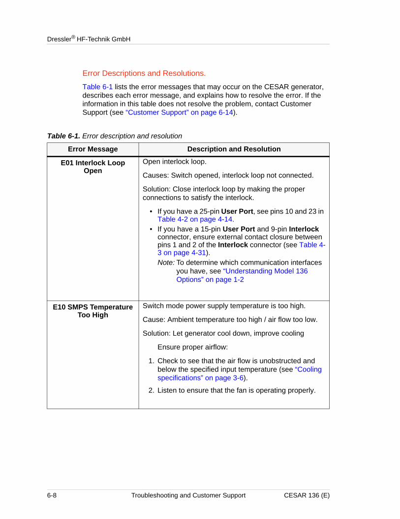
Dressler® HF-Technik GmbH
Error Descriptions and Resolutions.
Table 6-1 lists the error messages that may occur on the CESAR generator, describes each error message, and explains how to resolve the error. If the information in this table does not resolve the problem, contact Customer Support (see “Customer Support” on page 6-14).
Table 6-1. Error description and resolution
Error Message Description and Resolution
E01 Interlock Loop Open
Open interlock loop.
Causes: Switch opened, interlock loop not connected.
Solution: Close interlock loop by making the proper connections to satisfy the interlock.
• If you have a 25-pin User Port, see pins 10 and 23 in Table 4-2 on page 4-14.
• If you have a 15-pin User Port and 9-pin Interlock connector, ensure external contact closure between pins 1 and 2 of the Interlock connector (see Table 4-3 on page 4-31).Note: To determine which communication interfaces
you have, see “Understanding Model 136 Options” on page 1-2
E10 SMPS Temperature Too High
Switch mode power supply temperature is too high.
Cause: Ambient temperature too high / air flow too low.
Solution: Let generator cool down, improve cooling
Ensure proper airflow:
1. Check to see that the air flow is unobstructed and below the specified input temperature (see “Cooling specifications” on page 3-6).
2. Listen to ensure that the fan is operating properly.
6-8 Troubleshooting and Customer Support CESAR 136 (E)
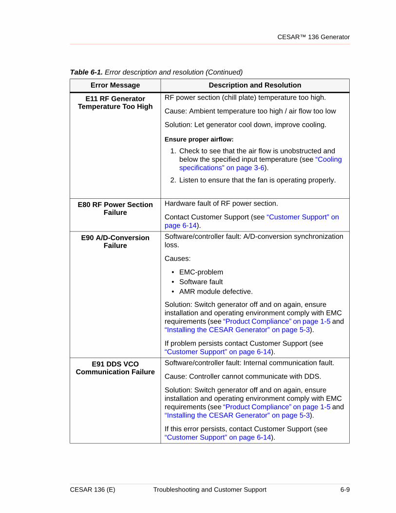
CESAR™ 136 Generator
E11 RF Generator Temperature Too High
RF power section (chill plate) temperature too high.
Cause: Ambient temperature too high / air flow too low
Solution: Let generator cool down, improve cooling.
Ensure proper airflow:
1. Check to see that the air flow is unobstructed and below the specified input temperature (see “Cooling specifications” on page 3-6).
2. Listen to ensure that the fan is operating properly.
E80 RF Power Section Failure
Hardware fault of RF power section.
Contact Customer Support (see “Customer Support” on page 6-14).
E90 A/D-Conversion Failure
Software/controller fault: A/D-conversion synchronization loss.
Causes:
• EMC-problem• Software fault• AMR module defective.
Solution: Switch generator off and on again, ensure installation and operating environment comply with EMC requirements (see “Product Compliance” on page 1-5 and “Installing the CESAR Generator” on page 5-3).
If problem persists contact Customer Support (see “Customer Support” on page 6-14).
E91 DDS VCO Communication Failure
Software/controller fault: Internal communication fault.
Cause: Controller cannot communicate with DDS.
Solution: Switch generator off and on again, ensure installation and operating environment comply with EMC requirements (see “Product Compliance” on page 1-5 and “Installing the CESAR Generator” on page 5-3).
If this error persists, contact Customer Support (see “Customer Support” on page 6-14).
Table 6-1. Error description and resolution (Continued)
Error Message Description and Resolution
CESAR 136 (E) Troubleshooting and Customer Support 6-9
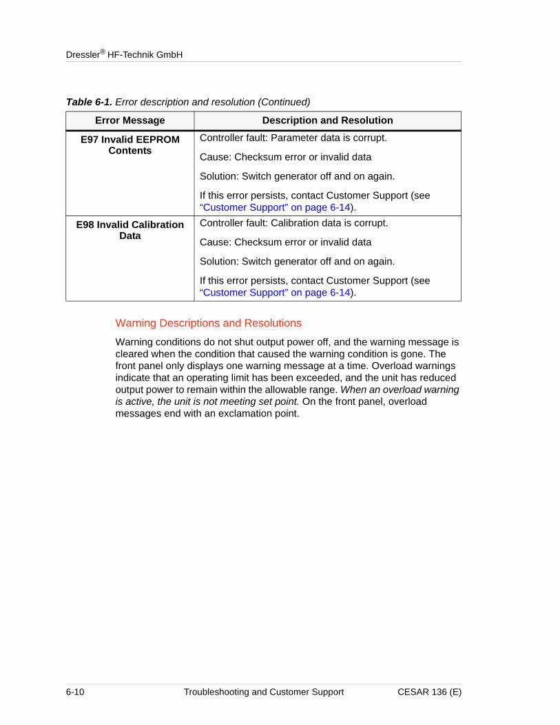
Dressler® HF-Technik GmbH
Warning Descriptions and Resolutions
Warning conditions do not shut output power off, and the warning message is cleared when the condition that caused the warning condition is gone. The front panel only displays one warning message at a time. Overload warnings indicate that an operating limit has been exceeded, and the unit has reduced output power to remain within the allowable range. When an overload warning is active, the unit is not meeting set point. On the front panel, overload messages end with an exclamation point.
E97 Invalid EEPROM Contents
Controller fault: Parameter data is corrupt.
Cause: Checksum error or invalid data
Solution: Switch generator off and on again.
If this error persists, contact Customer Support (see “Customer Support” on page 6-14).
E98 Invalid Calibration Data
Controller fault: Calibration data is corrupt.
Cause: Checksum error or invalid data
Solution: Switch generator off and on again.
If this error persists, contact Customer Support (see “Customer Support” on page 6-14).
Table 6-1. Error description and resolution (Continued)
Error Message Description and Resolution
6-10 Troubleshooting and Customer Support CESAR 136 (E)
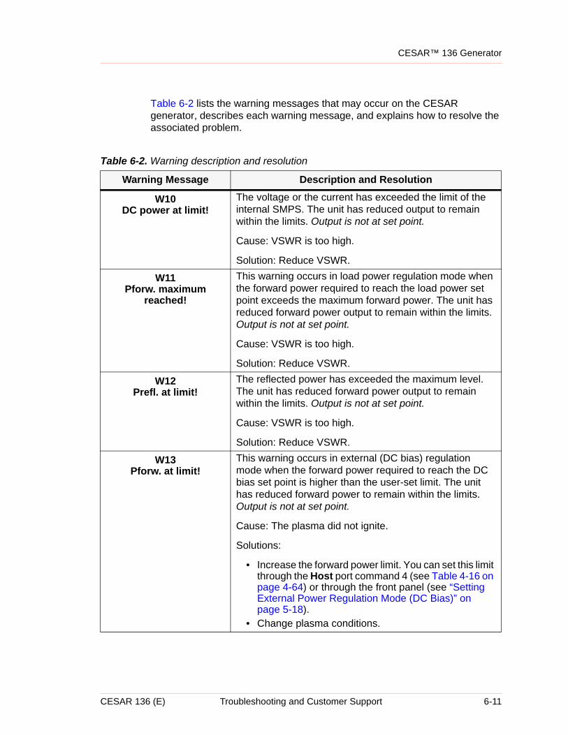
CESAR™ 136 Generator
Table 6-2 lists the warning messages that may occur on the CESAR generator, describes each warning message, and explains how to resolve the associated problem.
Table 6-2. Warning description and resolution
Warning Message Description and Resolution
W10DC power at limit!
The voltage or the current has exceeded the limit of the internal SMPS. The unit has reduced output to remain within the limits. Output is not at set point.
Cause: VSWR is too high.
Solution: Reduce VSWR.
W11Pforw. maximum
reached!
This warning occurs in load power regulation mode when the forward power required to reach the load power set point exceeds the maximum forward power. The unit has reduced forward power output to remain within the limits. Output is not at set point.
Cause: VSWR is too high.
Solution: Reduce VSWR.
W12Prefl. at limit!
The reflected power has exceeded the maximum level. The unit has reduced forward power output to remain within the limits. Output is not at set point.
Cause: VSWR is too high.
Solution: Reduce VSWR.
W13Pforw. at limit!
This warning occurs in external (DC bias) regulation mode when the forward power required to reach the DC bias set point is higher than the user-set limit. The unit has reduced forward power to remain within the limits. Output is not at set point.
Cause: The plasma did not ignite.
Solutions:
• Increase the forward power limit. You can set this limit through the Host port command 4 (see Table 4-16 on page 4-64) or through the front panel (see “Setting External Power Regulation Mode (DC Bias)” on page 5-18).
• Change plasma conditions.
CESAR 136 (E) Troubleshooting and Customer Support 6-11
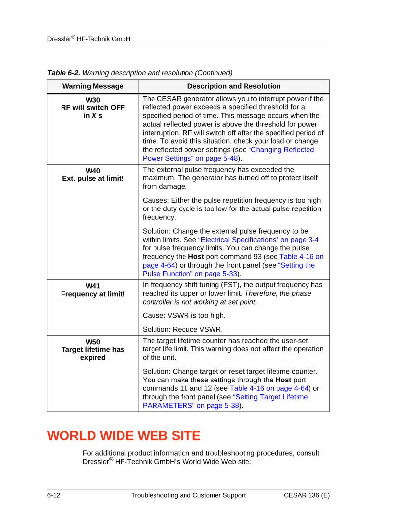
Dressler® HF-Technik GmbH
WORLD WIDE WEB SITEFor additional product information and troubleshooting procedures, consult Dressler® HF-Technik GmbH’s World Wide Web site:
W30RF will switch OFF
in X s
The CESAR generator allows you to interrupt power if the reflected power exceeds a specified threshold for a specified period of time. This message occurs when the actual reflected power is above the threshold for power interruption. RF will switch off after the specified period of time. To avoid this situation, check your load or change the reflected power settings (see “Changing Reflected Power Settings” on page 5-48).
W40Ext. pulse at limit!
The external pulse frequency has exceeded the maximum. The generator has turned off to protect itself from damage.
Causes: Either the pulse repetition frequency is too high or the duty cycle is too low for the actual pulse repetition frequency.
Solution: Change the external pulse frequency to be within limits. See “Electrical Specifications” on page 3-4 for pulse frequency limits. You can change the pulse frequency the Host port command 93 (see Table 4-16 on page 4-64) or through the front panel (see “Setting the Pulse Function” on page 5-33).
W41Frequency at limit!
In frequency shift tuning (FST), the output frequency has reached its upper or lower limit. Therefore, the phase controller is not working at set point.
Cause: VSWR is too high.
Solution: Reduce VSWR.
W50Target lifetime has
expired
The target lifetime counter has reached the user-set target life limit. This warning does not affect the operation of the unit.
Solution: Change target or reset target lifetime counter. You can make these settings through the Host port commands 11 and 12 (see Table 4-16 on page 4-64) or through the front panel (see “Setting Target Lifetime PARAMETERS” on page 5-38).
Table 6-2. Warning description and resolution (Continued)
Warning Message Description and Resolution
6-12 Troubleshooting and Customer Support CESAR 136 (E)
CESAR™ 136 Generator
• http://www.dressler.com
You may also visit our parent company’s World Wide Web site:
• http://www.advanced-energy.com
CESAR 136 (E) Troubleshooting and Customer Support 6-13
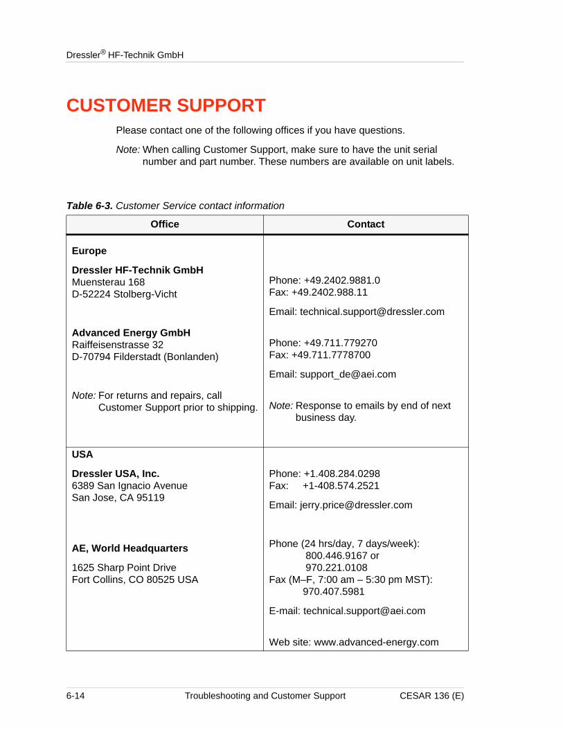
Dressler® HF-Technik GmbH
CUSTOMER SUPPORTPlease contact one of the following offices if you have questions.
Note: When calling Customer Support, make sure to have the unit serial number and part number. These numbers are available on unit labels.
Table 6-3. Customer Service contact information
Office Contact
Europe
Dressler HF-Technik GmbHMuensterau 168 D-52224 Stolberg-Vicht
Advanced Energy GmbHRaiffeisenstrasse 32D-70794 Filderstadt (Bonlanden)
Note: For returns and repairs, call Customer Support prior to shipping.
Phone: +49.2402.9881.0Fax: +49.2402.988.11
Email: [email protected]
Phone: +49.711.779270Fax: +49.711.7778700
Email: [email protected]
Note: Response to emails by end of next business day.
USA
Dressler USA, Inc.6389 San Ignacio AvenueSan Jose, CA 95119
AE, World Headquarters
1625 Sharp Point DriveFort Collins, CO 80525 USA
Phone: +1.408.284.0298Fax: +1-408.574.2521
Email: [email protected]
Phone (24 hrs/day, 7 days/week): 800.446.9167 or 970.221.0108Fax (M–F, 7:00 am – 5:30 pm MST): 970.407.5981
E-mail: [email protected]
Web site: www.advanced-energy.com
6-14 Troubleshooting and Customer Support CESAR 136 (E)
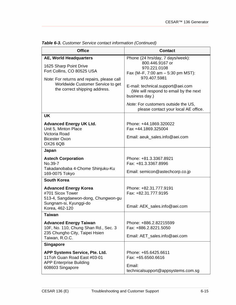
CESAR™ 136 Generator
AE, World Headquarters
1625 Sharp Point DriveFort Collins, CO 80525 USA
Note: For returns and repairs, please call Worldwide Customer Service to get the correct shipping address.
Phone (24 hrs/day, 7 days/week): 800.446.9167 or 970.221.0108Fax (M–F, 7:00 am – 5:30 pm MST): 970.407.5981
E-mail: [email protected] (We will respond to email by the next business day.)
Note: For customers outside the US, please contact your local AE office.
UK
Advanced Energy UK Ltd.Unit 5, Minton PlaceVictoria RoadBicester Oxon OX26 6QB
Phone: +44.1869.320022 Fax +44.1869.325004
Email: [email protected]
Japan
Astech Corporation No.39-7Takadanobaba 4-Chome Shinjuku-Ku 169-0075 Tokyo
Phone: +81.3.3367.8921Fax: +81.3.3367.8996
Email: [email protected]
South Korea
Advanced Energy Korea#701 Sicox Tower513-4, Sangdaewon-dong, Chungwon-guSungnam-si, Kyunggi-doKorea, 462-120
Phone: +82.31.777.9191Fax: +82.31.777.9195
Email: [email protected]
Taiwan
Advanced Energy Taiwan10F, No. 110, Chung Shan Rd., Sec. 3235 Chungho City, Taipei HsienTaiwan, R.O.C.
Phone: +886.2.82215599Fax: +886.2.8221.5050
Email: [email protected]
Singapore
APP Systems Service, Pte. Ltd.11Toh Guan Road East #03-01APP Enterprise Building 608603 Singapore
Phone: +65.6425.6611Fax: +65.6560.6616
Email: [email protected]
Table 6-3. Customer Service contact information (Continued)
Office Contact
CESAR 136 (E) Troubleshooting and Customer Support 6-15
Dressler® HF-Technik GmbH
RETURNING UNITS FOR REPAIRBefore returning any product for repair and/or adjustment, first follow all troubleshooting procedures. If the error or problem persists after following these procedures, please call your Customer Support office. Be prepared to give the model number and serial number of the unit, as well as the reason for the proposed return. This consultation call allows Customer Support to determine whether the problem can be corrected in the field or if the unit needs to be returned. Such technical consultation is always free of charge.
If you return a unit without first getting authorization from Customer Support and that unit is found to be functional, you will be charged a re-test and calibration fee plus shipping charges.
To ensure years of dependable service, Dressler® HF-Technik GmbH products are thoroughly tested and designed to be among the most reliable and highest quality systems available worldwide.
WARRANTYDressler® HF-Technik GmbH products are warranted to be free from failures due to defects in material and workmanship for 12 months (24 months in Europe) after they are shipped from the factory (please see warranty statement below, for details).
In order to claim shipping or handling damage, you must inspect the delivered goods and report such damage to Dressler® HF-Technik GmbH within 30 days of your receipt of the goods. Please note that failing to report any damage within this period is the same as acknowledging that the goods were received undamaged.
For a warranty claim to be valid, it must:
• Be made within the applicable warranty period
• Include the product serial number and a full description of the circumstances giving rise to the claim
• Have been assigned a return material authorization number (see below) by Customer Support
All warranty work will be performed at an authorized service center (see list of contacts at the beginning of this chapter). You are responsible for obtaining authorization (see details below) to return any defective units, prepaying the freight costs, and ensuring that the units are returned to an authorized service center. Dressler® HF-Technik GmbH will return the repaired unit (freight prepaid) to you by second-day air shipment (or ground carrier for local
6-16 Troubleshooting and Customer Support CESAR 136 (E)
CESAR™ 136 Generator
returns); repair parts and labor will be provided free of charge. Whoever ships the unit (either you or Dressler® HF-Technik GmbH) is responsible for properly packaging and adequately insuring the unit.
Authorized ReturnsBefore returning any product for repair and/or adjustment, call Customer Support and discuss the problem with them. Be prepared to give them the model number and serial number of the unit as well as the reason for the proposed return. This consultation call will allow Customer Support to determine if the unit must actually be returned for the problem to be corrected. Such technical consultation is always available at no charge.
Units that are returned without authorization from Customer Support and that are found to be functional will not be covered under the warranty (see warranty statement, below). That is, you will have to pay a retest and calibration fee, and all shipping charges.
Warranty StatementThe seller makes no express or implied warranty that the goods are merchantable or fit for any particular purpose except as specifically stated in printed specifications. The sole responsibility of the Seller shall be that it will manufacture the goods in accordance with its published specifications and that the goods will be free from defects in material and workmanship. The seller's liability for breach of an expressed warranty shall exist only if the goods are installed, started in operation, and tested in conformity with the seller's published instructions. The seller expressly excludes any warranty whatsoever concerning goods that have been subject to misuse, negligence, or accident, or that have been altered or repaired by anyone other than the seller or the seller's duly authorized agent. This warranty is expressly made in lieu of any and all other warranties, express or implied, unless otherwise agreed to in writing. The warranty period is 12 months (24 months in Europe) after the date the goods are shipped from Dressler® HF-Technik GmbH. In all cases, the seller has sole responsibility for determining the cause and nature of the failure, and the seller's determination with regard thereto shall be final. The Warranty Statement may be superseded by a service agreement entered into between Dressler® HF-Technik GmbH and the buyer.
CESAR 136 (E) Troubleshooting and Customer Support 6-17

Dressler® HF-Technik GmbH
6-18 Troubleshooting and Customer Support CESAR 136 (E)
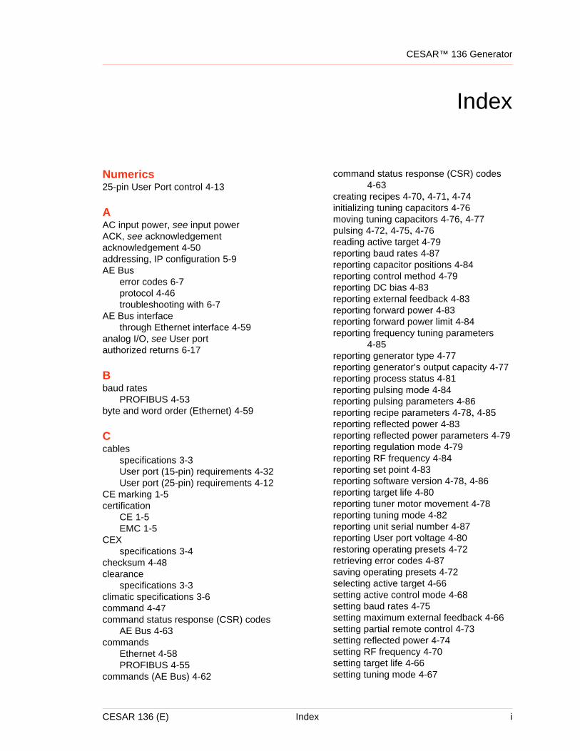
CESAR™ 136 Generator
Index
Numerics25-pin User Port control 4-13
AAC input power, see input powerACK, see acknowledgementacknowledgement 4-50addressing, IP configuration 5-9AE Bus
error codes 6-7protocol 4-46troubleshooting with 6-7
AE Bus interfacethrough Ethernet interface 4-59
analog I/O, see User portauthorized returns 6-17
Bbaud rates
PROFIBUS 4-53byte and word order (Ethernet) 4-59
Ccables
specifications 3-3User port (15-pin) requirements 4-32User port (25-pin) requirements 4-12
CE marking 1-5certification
CE 1-5EMC 1-5
CEXspecifications 3-4
checksum 4-48clearance
specifications 3-3climatic specifications 3-6command 4-47command status response (CSR) codes
AE Bus 4-63commands
Ethernet 4-58PROFIBUS 4-55
commands (AE Bus) 4-62
command status response (CSR) codes 4-63
creating recipes 4-70, 4-71, 4-74initializing tuning capacitors 4-76moving tuning capacitors 4-76, 4-77pulsing 4-72, 4-75, 4-76reading active target 4-79reporting baud rates 4-87reporting capacitor positions 4-84reporting control method 4-79reporting DC bias 4-83reporting external feedback 4-83reporting forward power 4-83reporting forward power limit 4-84reporting frequency tuning parameters
4-85reporting generator type 4-77reporting generator’s output capacity 4-77reporting process status 4-81reporting pulsing mode 4-84reporting pulsing parameters 4-86reporting recipe parameters 4-78, 4-85reporting reflected power 4-83reporting reflected power parameters 4-79reporting regulation mode 4-79reporting RF frequency 4-84reporting set point 4-83reporting software version 4-78, 4-86reporting target life 4-80reporting tuner motor movement 4-78reporting tuning mode 4-82reporting unit serial number 4-87reporting User port voltage 4-80restoring operating presets 4-72retrieving error codes 4-87saving operating presets 4-72selecting active target 4-66setting active control mode 4-68setting baud rates 4-75setting maximum external feedback 4-66setting partial remote control 4-73setting reflected power 4-74setting RF frequency 4-70setting target life 4-66setting tuning mode 4-67
CESAR 136 (E) Index i
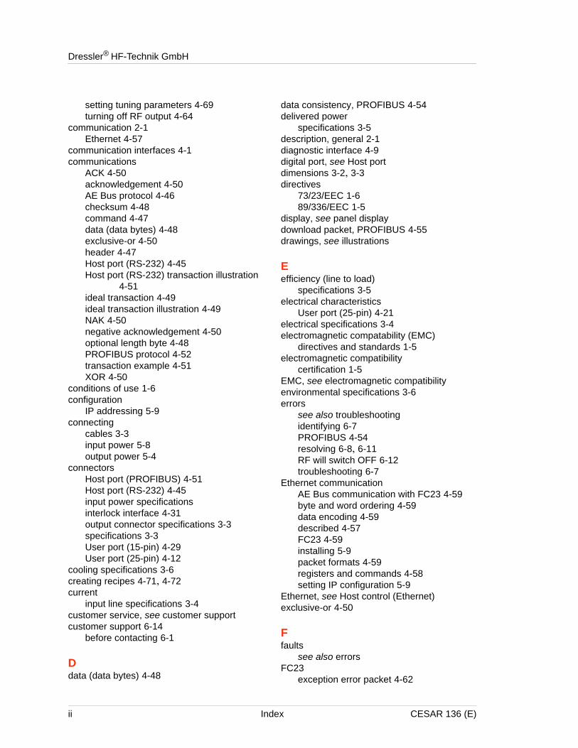
Dressler® HF-Technik GmbH
setting tuning parameters 4-69turning off RF output 4-64
communication 2-1Ethernet 4-57
communication interfaces 4-1communications
ACK 4-50acknowledgement 4-50AE Bus protocol 4-46checksum 4-48command 4-47data (data bytes) 4-48exclusive-or 4-50header 4-47Host port (RS-232) 4-45Host port (RS-232) transaction illustration
4-51ideal transaction 4-49ideal transaction illustration 4-49NAK 4-50negative acknowledgement 4-50optional length byte 4-48PROFIBUS protocol 4-52transaction example 4-51XOR 4-50
conditions of use 1-6configuration
IP addressing 5-9connecting
cables 3-3input power 5-8output power 5-4
connectorsHost port (PROFIBUS) 4-51Host port (RS-232) 4-45input power specificationsinterlock interface 4-31output connector specifications 3-3specifications 3-3User port (15-pin) 4-29User port (25-pin) 4-12
cooling specifications 3-6creating recipes 4-71, 4-72current
input line specifications 3-4customer service, see customer supportcustomer support 6-14
before contacting 6-1
Ddata (data bytes) 4-48
data consistency, PROFIBUS 4-54delivered power
specifications 3-5description, general 2-1diagnostic interface 4-9digital port, see Host portdimensions 3-2, 3-3directives
73/23/EEC 1-689/336/EEC 1-5
display, see panel displaydownload packet, PROFIBUS 4-55drawings, see illustrations
Eefficiency (line to load)
specifications 3-5electrical characteristics
User port (25-pin) 4-21electrical specifications 3-4electromagnetic compatability (EMC)
directives and standards 1-5electromagnetic compatibility
certification 1-5EMC, see electromagnetic compatibilityenvironmental specifications 3-6errors
see also troubleshootingidentifying 6-7PROFIBUS 4-54resolving 6-8, 6-11RF will switch OFF 6-12troubleshooting 6-7
Ethernet communicationAE Bus communication with FC23 4-59byte and word ordering 4-59data encoding 4-59described 4-57FC23 4-59installing 5-9packet formats 4-59registers and commands 4-58setting IP configuration 5-9
Ethernet, see Host control (Ethernet)exclusive-or 4-50
Ffaults
see also errorsFC23
exception error packet 4-62
ii Index CESAR 136 (E)
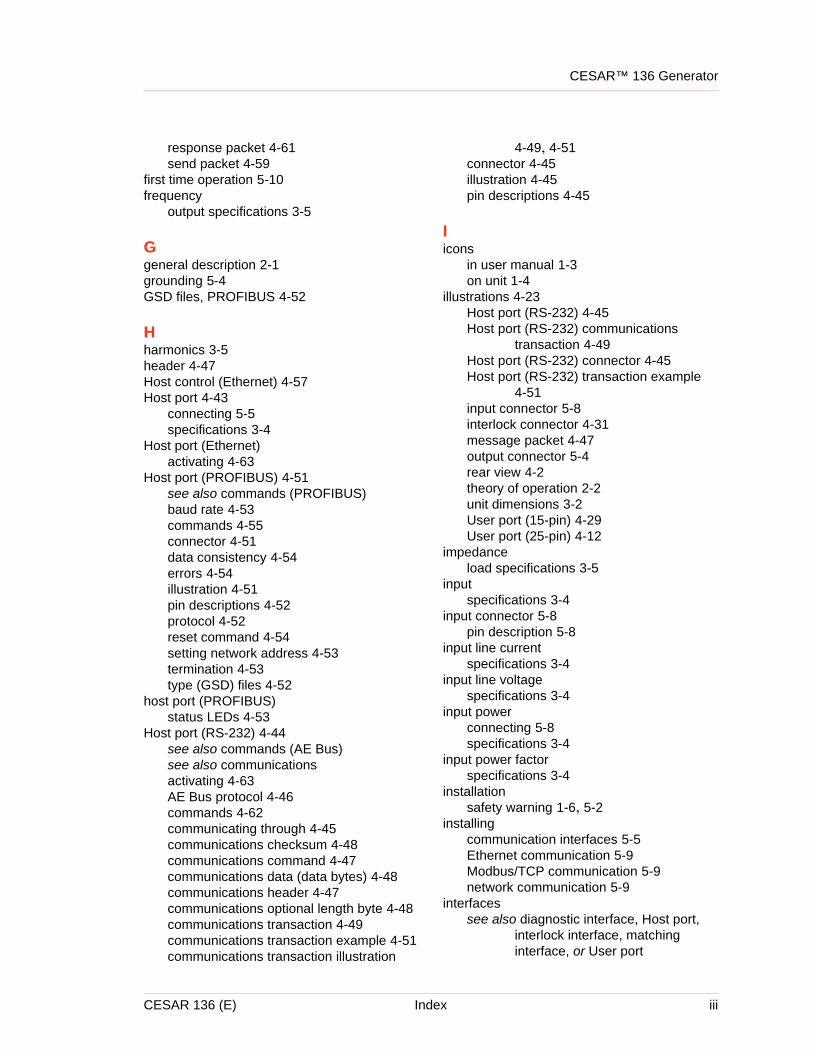
CESAR™ 136 Generator
response packet 4-61send packet 4-59
first time operation 5-10frequency
output specifications 3-5
Ggeneral description 2-1grounding 5-4GSD files, PROFIBUS 4-52
Hharmonics 3-5header 4-47Host control (Ethernet) 4-57Host port 4-43
connecting 5-5specifications 3-4
Host port (Ethernet)activating 4-63
Host port (PROFIBUS) 4-51see also commands (PROFIBUS)baud rate 4-53commands 4-55connector 4-51data consistency 4-54errors 4-54illustration 4-51pin descriptions 4-52protocol 4-52reset command 4-54setting network address 4-53termination 4-53type (GSD) files 4-52
host port (PROFIBUS)status LEDs 4-53
Host port (RS-232) 4-44see also commands (AE Bus)see also communicationsactivating 4-63AE Bus protocol 4-46commands 4-62communicating through 4-45communications checksum 4-48communications command 4-47communications data (data bytes) 4-48communications header 4-47communications optional length byte 4-48communications transaction 4-49communications transaction example 4-51communications transaction illustration
4-49, 4-51connector 4-45illustration 4-45pin descriptions 4-45
Iicons
in user manual 1-3on unit 1-4
illustrations 4-23Host port (RS-232) 4-45Host port (RS-232) communications
transaction 4-49Host port (RS-232) connector 4-45Host port (RS-232) transaction example
4-51input connector 5-8interlock connector 4-31message packet 4-47output connector 5-4rear view 4-2theory of operation 2-2unit dimensions 3-2User port (15-pin) 4-29User port (25-pin) 4-12
impedanceload specifications 3-5
inputspecifications 3-4
input connector 5-8pin description 5-8
input line currentspecifications 3-4
input line voltagespecifications 3-4
input powerconnecting 5-8specifications 3-4
input power factorspecifications 3-4
installationsafety warning 1-6, 5-2
installingcommunication interfaces 5-5Ethernet communication 5-9Modbus/TCP communication 5-9network communication 5-9
interfacessee also diagnostic interface, Host port,
interlock interface, matching interface, or User port
CESAR 136 (E) Index iii
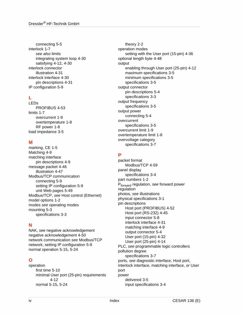
Dressler® HF-Technik GmbH
connecting 5-5interlock 1-7
see also limitsintegrating system loop 4-30satisfying 4-12, 4-30
interlock connectorillustration 4-31
interlock interface 4-30pin descriptions 4-31
IP configuration 5-9
LLEDs
PROFIBUS 4-53limits 1-7
overcurrent 1-9overtemperature 1-8RF power 1-8
load impedance 3-5
Mmarking, CE 1-5Matching 4-9matching interface
pin descriptions 4-9message packet 4-46
illustration 4-47Modbus/TCP communication
connecting 5-9setting IP configuration 5-9unit Web pages 5-49
Modbus/TCP, see Host control (Ethernet)model options 1-2modes see operating modesmounting 5-3
specifications 3-3
NNAK, see negative acknowledgementnegative acknowledgement 4-50network communication see Modbus/TCPnetwork, setting IP configuration 5-9normal operation 5-15, 5-24
Ooperation
first time 5-10minimal User port (25-pin) requirements
4-12normal 5-15, 5-24
theory 2-2operation modes
setting with the User port (15-pin) 4-36optional length byte 4-48output
enabling through User port (25-pin) 4-12maximum specifications 3-5minimum specifications 3-5specifications 3-5
output connectorpin descriptions 5-4specifications 3-3
output frequencyspecifications 3-5
output powerconnecting 5-4
overcurrentspecifications 3-5
overcurrent limit 1-9overtemperature limit 1-8overvoltage category
specifications 3-7
Ppacket format
Modbus/TCP 4-59panel display
specifications 3-4part numbers 1-2Pforward regulation, see forward power regulationphotos, see illustrationsphysical specifications 3-1pin descriptions
Host port (PROFIBUS) 4-52Host port (RS-232) 4-45input connector 5-8interlock interface 4-31matching interface 4-9output connector 5-4User port (15-pin) 4-32User port (25-pin) 4-14
PLC, see programmable logic controllerspollution degree
specifications 3-7ports, see diagnostic interface, Host port, interlock interface, matching interface, or User portpower
delivered 3-5input specifications 3-4
iv Index CESAR 136 (E)
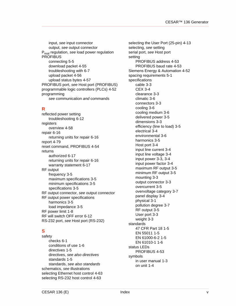
CESAR™ 136 Generator
input, see input connectoroutput, see output connector
Preal regulation, see load power regulationPROFIBUS
connecting 5-5download packet 4-55troubleshooting with 6-7upload packet 4-56upload status bytes 4-57
PROFIBUS port, see Host port (PROFIBUS)programmable logic controllers (PLCs) 4-52programming
see communication and commands
Rreflected power setting
troubleshooting 6-12registers
overview 4-58repair 6-16
returning units for repair 6-16report 4-79reset command, PROFIBUS 4-54returns
authorized 6-17returning units for repair 6-16warranty statement 6-17
RF outputfrequency 3-5maximum specifications 3-5minimum specifications 3-5specifications 3-5
RF output connector, see output connectorRF output power specifications
harmonics 3-5load impedance 3-5
RF power limit 1-8RF will switch OFF error 6-12RS-232 port, see Host port (RS-232)
Ssafety
checks 6-1conditions of use 1-6directives 1-5directives, see also directivesstandards 1-5standards, see also standards
schematics, see illustrationsselecting Ethernet host control 4-63selecting RS-232 host control 4-63
selecting the User Port (25-pin) 4-13selecting, see settingserial port, see Host portsetting
PROFIBUS address 4-53PROFIBUS baud rate 4-53
Siemens Energy & Automation 4-52spacing requirements 5-1specifications
cable 3-3CEX 3-4clearance 3-3climatic 3-6connectors 3-3cooling 3-6cooling medium 3-6delivered power 3-5dimensions 3-3efficiency (line to load) 3-5electrical 3-4environmental 3-6harmonics 3-5Host port 3-4input line current 3-4input line voltage 3-4input power 3-3, 3-4input power factor 3-4maximum RF output 3-5minimum RF output 3-5mounting 3-3output connector 3-3overcurrent 3-5overvoltage category 3-7panel display 3-4physical 3-1pollution degree 3-7RF output 3-5User port 3-3weight 3-3
standards47 CFR Part 18 1-5EN 55011 1-5EN 61000-6-2 1-5EN 61010-1 1-6
status LEDsPROFIBUS 4-53
symbolsin user manual 1-3on unit 1-4
CESAR 136 (E) Index v
Dressler® HF-Technik GmbH
TTCP, see Host control (Ethernet)termination procedure, PROFIBUS 4-53theory of operation 2-2troubleshooting
see also errorscapacitor failure 6-4communication problems 6-4error conditions 6-7incorrect input voltage 6-5
troubleshooting information 6-2tuning
modes 2-1type files, PROFIBUS 4-52
Uunit
setting IP configuration 5-9unit options 1-2unit Web pages 5-49unpacking 5-3upload packet, PROFIBUS 4-56upload status bytes, PROFIBUS 4-57user manual
symbols used 1-4User port
connecting 5-5specifications 3-3
User port (15-pin) 4-29assessing maximum power 4-33cable requirements 4-32enabling RF power 4-35illustration 4-29monitoring errors 4-33pin descriptions 4-32pulsing 4-34selecting forward power 4-35setting a set point 4-35setting operation modes 4-36setting the operating mode 4-32wiring diagrams 4-37
User Port (25-pin)activating 4-13
User port (25-pin) 4-11analog inputs 4-21analog outputs 4-22cable requirements 4-12connector 4-12digital inputs 4-22digital outputs 4-22electrical characteristics 4-21
enabling RF power 4-16monitoring forward power 4-15monitoring load power 4-15monitoring overtemperature 4-20monitoring reflected power 4-14monitoring set point status 4-20pin descriptions 4-14satisfying circuits for operation 4-12setting a set point 4-17wiring diagrams 4-23
User port (25-pin) wiring diagrams 4-23
Vviews, see illustrationsVirtual Front Panel
troubleshooting with 6-7voltage
input line specifications 3-4
Wwarranty
authorized returns 6-17filing a claim 6-16returning units 6-17statement 6-17
Web pages, for unit 5-49weight 3-3wiring diagrams, User port (15-pin) 4-37World Wide Web sites 6-12
XXOR, see exclusive-or
vi Index CESAR 136 (E)