Embed Size (px)
Citation preview
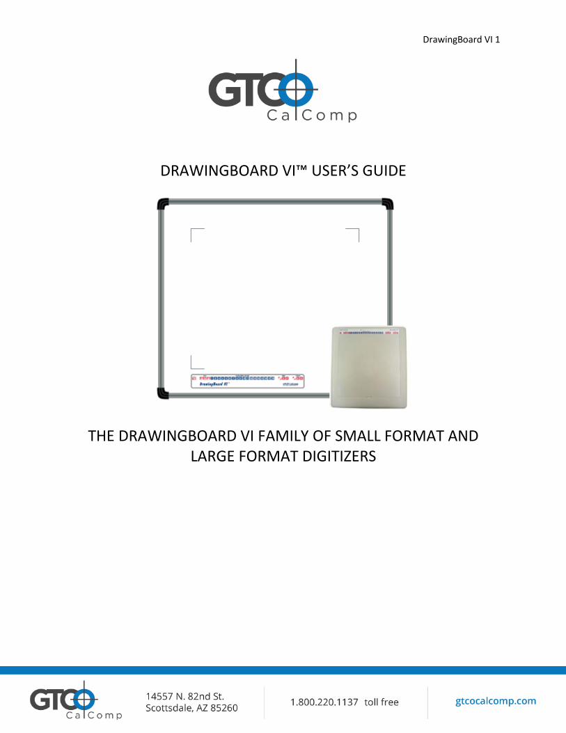
DrawingBoard VI 1
DRAWINGBOARD VI™ USER’S GUIDE
THE DRAWINGBOARD VI FAMILY OF SMALL FORMAT AND LARGE FORMAT DIGITIZERS
DrawingBoard VI 2
Table of Contents
Introduction Parts Checklist What You Will Need to Use DrawingBoard VI PC Requirements For a USB Installation For an Optional Serial Installation DrawingBoard VI Overview Active Area Menu Strip Indicator Light Transducers Preparing the Large Format DrawingBoard VI Mounting on a Stand Attaching the Accessory Tray or Plan Holder Software Configuration Configuring Non-Wintab Applications Installing the TabletWorks Driver Hardware Configuration USB Connection Optional RS-232 Serial Connection Tablet Power-On Customizing the Tablet Overview of the Menu Strip Selecting a Pre-Programmed Setup Selecting a Custom Setup Tablet Options Recommended Setups for Common PC Software Applications Restoring a Pre-Programmed Setup Learning the Basics Using the Transducer Using the Cursor Using the Pen Learning Basic Movements Clicking and Double-Clicking Dragging Caring for the Tablet and Transducer Cleaning the Tablet Cleaning the Cursor Replacing the Pen Tip Replacing the Cordless Pen Batteries Replacing the Cordless Cursor Batteries
3 4 5 5 5 5 6 6 6 6 7 7 7 7 8 8 8 9 9 10 11 11 11 12 13 14 20 24 25 25 25 25 26 26 26 27 27 27 28 28 28
DrawingBoard VI 3
Troubleshooting Tablet Checklist Computer Checklist Software Checklist Troubleshooting Chart Returning your Tablet for Repair Repacking for Shipment Parts and Accessories Glossary Regulatory Statements and Warranty Radio and Television Interference Canada European Union Emission Directive European Union WEEE Directive Japan Bescheinigung des Herstellers/Importeurs Limited Warranty for the DrawingBoard VI
30 31 31 32 33 34 34 34 35 38 38 39 39 39 40 40 41
Introduction
DrawingBoard VI belongs to a class of computer input devices called graphics tablets, or digitizers. A digitizer is an electronic tablet work surface. The position of a transducer, a handheld cursor or stylus pen, on the work surface of the DrawingBoard VI is converted – digitized – into data for computer processing. Data output from the DrawingBoard VI digitizer is in the form of an X/Y coordinate pair that pinpoints the precise location of the transducer on the tablet surface. By placing a drawing or sketch on the tablet’s surface and tracing over it, graphical information can be easily converted into accurate digital information for entry into the computer. DrawingBoard VI digitizers utilize the same Advanced Function Technology that has set the world standard for performance since 1975. These high performance tools are Engineered with a state-of-the-art positioning grid to ensure reliability, performance and quality. Multiple accuracy versions are available to meet specific system requirements.
The DrawingBoard VI family of small and large format digitizers boasts the highest resolution, 12,700 lines per inch, on the market today, unparalleled accuracy and a wide range of sizes, providing the perfect solution when the work demands precision data input, particularly over a large surface area. CAD, GIS, engineering, textile and apparel designers appreciate the variety of cordless and corded cursors and stylus pens available to use with DrawingBoard VI. An integrated mounting channel on the large format frame allows components, such as an accessory tray, to be quickly and easily mounted. The Tabletworks Driver offers programmable
DrawingBoard VI 4
function keys to round out the picture of a powerful, versatile tool that can be configured to meet the needs of any application environment from drawing, animation, presentation graphics and desktop publishing to drafting and mapping. The high-productivity DrawingBoard VI can be used as both a digitizer and a mouse, eliminating the need for multiple devices at your computer.
In order to send data to a digitizing application, DrawingBoard VI must be physically connected to a computer and should be able to transmit data in such a way that the digitizing application recognizes and understands it. Before setting up DrawingBoard VI, you should determine:
Requirements of the digitizing software application being used Whether the digitizing application requires software drivers to communicate with
DrawingBoard VI Hardware communications connection (USB or serial) being used between DrawingBoard
VI and the computer
Parts Checklist
DrawingBoard VI digitizer/tablet Transducer (corded or cordless pen,
4-button or 16-button cursor) USB cable
Universal mounting brackets Accessory Tray Warranty Sheet
Optional Equipment
RS-232 serial kit (power supply and cable)
Clear overlay*
Versa Table*
*For Large Format Digitizer Only
DrawingBoard VI 5
What You Will Need to Use DrawingBoard VI
PC Requirements
DrawingBoard VI is equipped with both a USB and RS-232 serial interface, which requires an optional RS-232 cable and power supply. It is compatible with a majority of industry-standard PCs. TabletWorks Driver is provided by GTCO CalComp and is the only software described in this manual. TabletWorks supports Wintab and TabCon-compatible applications. If you are not sure if Tabletworks is required, please consult with your application vendor.
A USB connection requires the use of a TabletWorks driver, while a serial connection requires the use of a TabletWorks driver and/or a custom application program. After installing the TabletWorks software, DrawingBoard VI will work with all Windows-based applications specifically designed for use with digitizers.
For a USB Installation
Microsoft Windows 7, 8 or 10 One available USB port 10 MB of free disk space Application software that accepts digitizer input via the Wintab API or TabCon API
For an Optional Serial Installation
Microsoft Windows 7, 8 or 10 One available RS-232C serial communication port (Serial signal levels must conform to
EIA RS-232C specifications) 10 MB of free disk space Application software that directly accepts digitizer input via the computer’s RS-232C
serial port, or via the Wintab API or TabCon API
DrawingBoard VI 6
DrawingBoard VI Overview
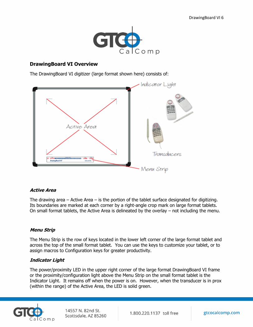
The DrawingBoard VI digitizer (large format shown here) consists of:
Active Area
The drawing area – Active Area – is the portion of the tablet surface designated for digitizing. Its boundaries are marked at each corner by a right-angle crop mark on large format tablets. On small format tablets, the Active Area is delineated by the overlay – not including the menu.
Menu Strip
The Menu Strip is the row of keys located in the lower left corner of the large format tablet and across the top of the small format tablet. You can use the keys to customize your tablet, or to assign macros to Configuration keys for greater productivity.
Indicator Light
The power/proximity LED in the upper right corner of the large format DrawingBoard VI frame or the proximity/configuration light above the Menu Strip on the small format tablet is the Indicator Light. It remains off when the power is on. However, when the transducer is in prox (within the range) of the Active Area, the LED is solid green.
DrawingBoard VI 7
Transducer
Two types of transducers can be used with DrawingBoard VI: pens and cursors. Both are available in corded and cordless versions. The corded transducers receive power from the digitizer. Cordless transducers are powered by batteries. They will go into a battery-saving Sleep Mode when no button has been pressed for one to five minutes, depending on the type of transducer being used. To reactivate a sleeping transducer, press one of its buttons.
Cursors
The cursor is similar in appearance to a mouse, except that it has an attached lens with crosshairs for highly accurate detail work. Cursors are available in 4 or 16 button models.
Pens
Each pen corded and cordless are similar in appearance to a ballpoint pen. The pen transducer has three buttons, two on the side of the barrel and one in the pen tip.
Preparing the Large Format DrawingBoard VI
Mounting on a Stand
Visit our Website www.gtcocalcomp.com to see our Recommended Tilt Stand
(Versa Table)
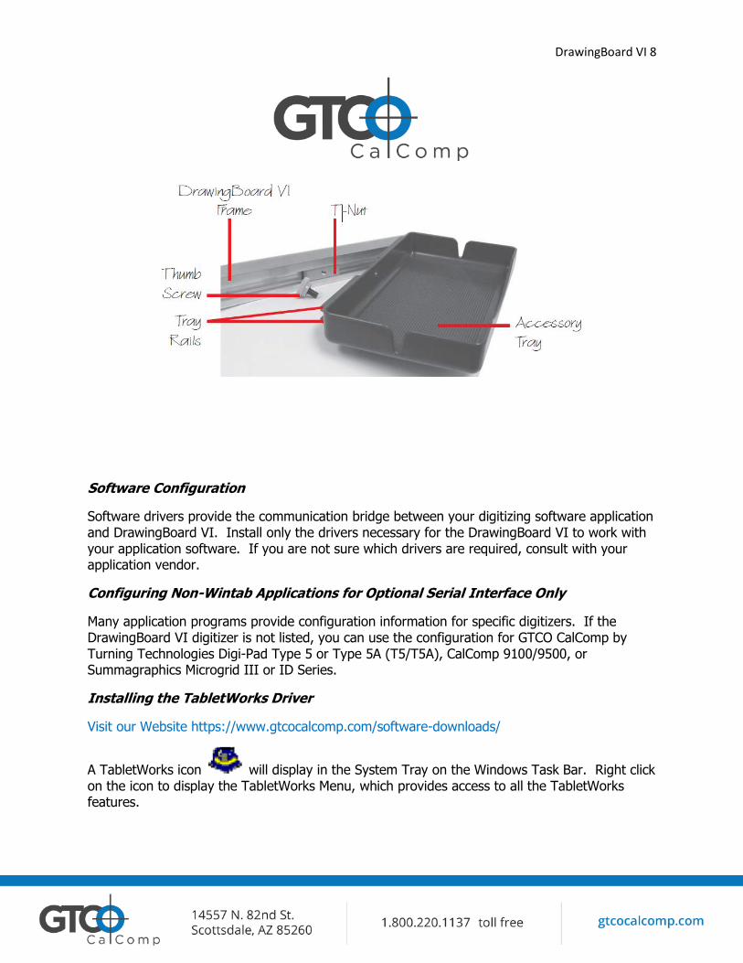
Attaching the Accessory Tray or the Optional Plan Holder
Additional T-Nuts have been included in the perimeter mounting channels on the DrawingBoard VI frame. You can position the Plan Holder or Accessory Tray where it is most convenient for you by attaching it to any one of the available T-Nuts. The following instructions and the graphic below detail the installation of the Accessory Tray.
Simply slide the Tray Rails into the channel and line up the hole in the tray with the hole in the T-Nut. Tighten the Thumb Screw to secure the Accessory Tray.
DrawingBoard VI 8
Software Configuration
Software drivers provide the communication bridge between your digitizing software application and DrawingBoard VI. Install only the drivers necessary for the DrawingBoard VI to work with your application software. If you are not sure which drivers are required, consult with your application vendor.
Configuring Non-Wintab Applications for Optional Serial Interface Only
Many application programs provide configuration information for specific digitizers. If the DrawingBoard VI digitizer is not listed, you can use the configuration for GTCO CalComp by Turning Technologies Digi-Pad Type 5 or Type 5A (T5/T5A), CalComp 9100/9500, or Summagraphics Microgrid III or ID Series.
Installing the TabletWorks Driver
Visit our Website https://www.gtcocalcomp.com/software-downloads/
A TabletWorks icon will display in the System Tray on the Windows Task Bar. Right click on the icon to display the TabletWorks Menu, which provides access to all the TabletWorks features.
DrawingBoard VI 9
Hardware Configuration
When you use the USB interface, no data output configuration is required. When you use the optional serial interface, DrawingBoard VI must be configured to send data in a format that is compatible with the application software. Different applications have different requirements when interacting with a digitizer. Determine if you have not already, which communication connection you will be using – USB or serial.
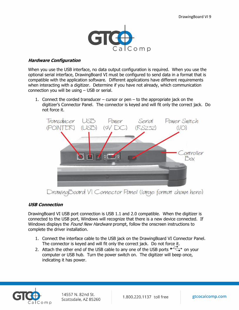
1. Connect the corded transducer – cursor or pen – to the appropriate jack on the digitizer’s Connector Panel. The connector is keyed and will fit only the correct jack. Do not force it.
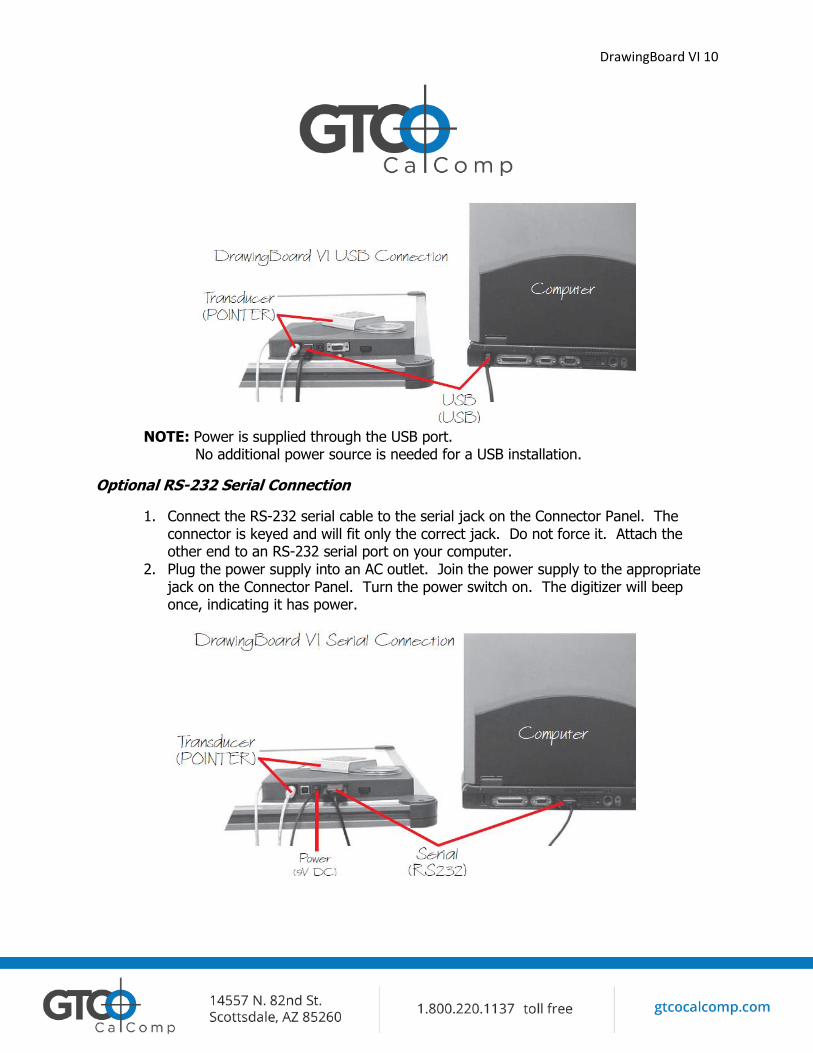
USB Connection
DrawingBoard VI USB port connection is USB 1.1 and 2.0 compatible. When the digitizer is connected to the USB port, Windows will recognize that there is a new device connected. If Windows displays the Found New Hardware prompt, follow the onscreen instructions to complete the driver installation.
1. Connect the interface cable to the USB jack on the DrawingBoard VI Connector Panel. The connector is keyed and will fit only the correct jack. Do not force it.
2. Attach the other end of the USB cable to any one of the USB ports on your computer or USB hub. Turn the power switch on. The digitizer will beep once, indicating it has power.
DrawingBoard VI 10
NOTE: Power is supplied through the USB port. No additional power source is needed for a USB installation.
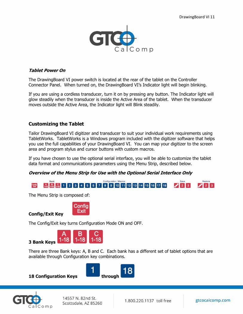
Optional RS-232 Serial Connection
1. Connect the RS-232 serial cable to the serial jack on the Connector Panel. The connector is keyed and will fit only the correct jack. Do not force it. Attach the other end to an RS-232 serial port on your computer.
2. Plug the power supply into an AC outlet. Join the power supply to the appropriate jack on the Connector Panel. Turn the power switch on. The digitizer will beep once, indicating it has power.
DrawingBoard VI 11
Tablet Power On
The DrawingBoard VI power switch is located at the rear of the tablet on the Controller Connector Panel. When turned on, the DrawingBoard VI’s Indicator light will begin blinking.
If you are using a cordless transducer, turn it on by pressing any button. The Indicator light will glow steadily when the transducer is inside the Active Area of the tablet. When the transducer moves outside the Active Area, the Indicator light will Blink steadily.
Customizing the Tablet
Tailor DrawingBoard VI digitizer and transducer to suit your individual work requirements using TabletWorks. TabletWorks is a Windows program included with the digitizer software that helps you use the full capabilities of your DrawingBoard VI. You can map your digitizer to the screen area and program stylus and cursor buttons with custom macros.
If you have chosen to use the optional serial interface, you will be able to customize the tablet data format and communications parameters using the Menu Strip, described below.
Overview of the Menu Strip for Use with the Optional Serial Interface Only
The Menu Strip is composed of:
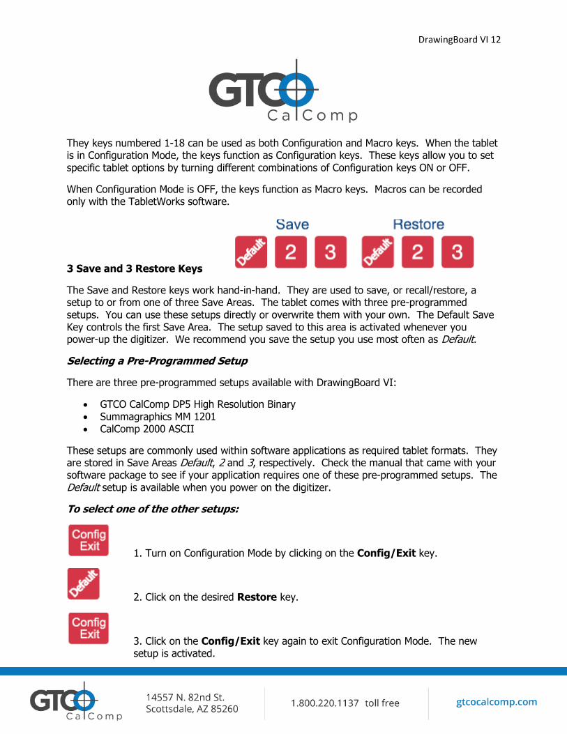
Config/Exit Key
The Config/Exit key turns Configuration Mode ON and OFF.
3 Bank Keys
There are three Bank keys: A, B and C. Each bank has a different set of tablet options that are available through Configuration key combinations.
18 Configuration Keys through
DrawingBoard VI 12
They keys numbered 1-18 can be used as both Configuration and Macro keys. When the tablet is in Configuration Mode, the keys function as Configuration keys. These keys allow you to set specific tablet options by turning different combinations of Configuration keys ON or OFF.
When Configuration Mode is OFF, the keys function as Macro keys. Macros can be recorded only with the TabletWorks software.
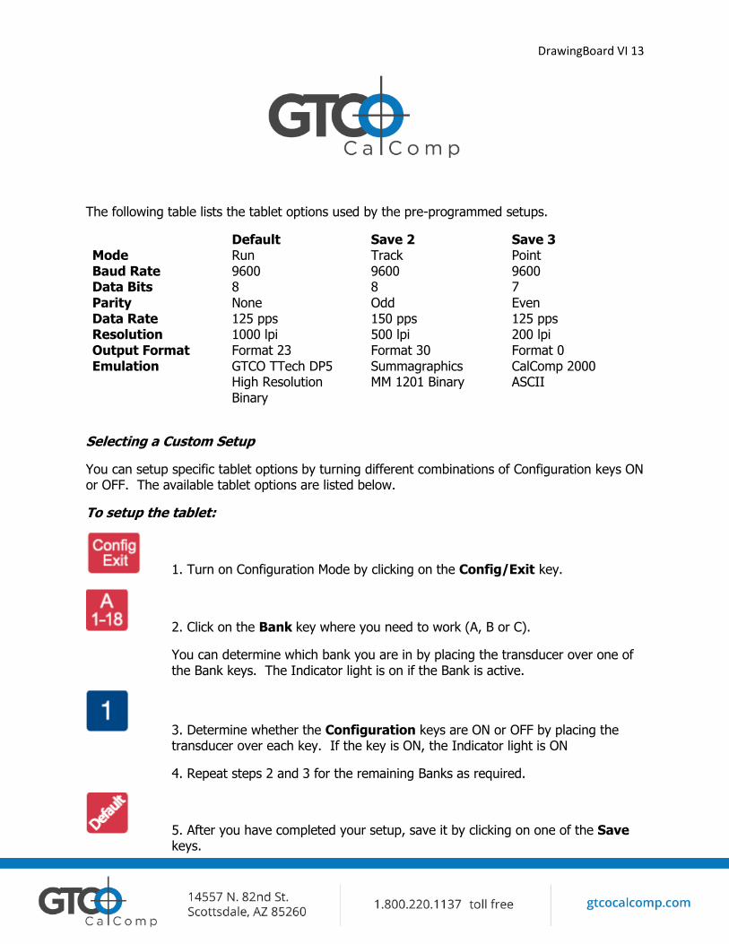
3 Save and 3 Restore Keys
The Save and Restore keys work hand-in-hand. They are used to save, or recall/restore, a setup to or from one of three Save Areas. The tablet comes with three pre-programmed setups. You can use these setups directly or overwrite them with your own. The Default Save Key controls the first Save Area. The setup saved to this area is activated whenever you power-up the digitizer. We recommend you save the setup you use most often as Default.
Selecting a Pre-Programmed Setup
There are three pre-programmed setups available with DrawingBoard VI:
GTCO CalComp DP5 High Resolution Binary Summagraphics MM 1201 CalComp 2000 ASCII
These setups are commonly used within software applications as required tablet formats. They are stored in Save Areas Default, 2 and 3, respectively. Check the manual that came with your software package to see if your application requires one of these pre-programmed setups. The Default setup is available when you power on the digitizer.
To select one of the other setups:
1. Turn on Configuration Mode by clicking on the Config/Exit key.
2. Click on the desired Restore key.
3. Click on the Config/Exit key again to exit Configuration Mode. The new setup is activated.
DrawingBoard VI 13
The following table lists the tablet options used by the pre-programmed setups.
Default Save 2 Save 3 Mode Run Track Point Baud Rate 9600 9600 9600 Data Bits 8 8 7 Parity None Odd Even Data Rate 125 pps 150 pps 125 pps Resolution 1000 lpi 500 lpi 200 lpi Output Format Format 23 Format 30 Format 0 Emulation GTCO TTech DP5
High Resolution Binary
Summagraphics MM 1201 Binary
CalComp 2000 ASCII
Selecting a Custom Setup
You can setup specific tablet options by turning different combinations of Configuration keys ON or OFF. The available tablet options are listed below.
To setup the tablet:
1. Turn on Configuration Mode by clicking on the Config/Exit key.
2. Click on the Bank key where you need to work (A, B or C).
You can determine which bank you are in by placing the transducer over one of the Bank keys. The Indicator light is on if the Bank is active.
3. Determine whether the Configuration keys are ON or OFF by placing the transducer over each key. If the key is ON, the Indicator light is ON
4. Repeat steps 2 and 3 for the remaining Banks as required.
5. After you have completed your setup, save it by clicking on one of the Save keys.
DrawingBoard VI 14
6. Exit Configuration Mode by clicking on the Config/Exit key.
Tablet Options
The following sections show the various tablet options available through Configuration keys on the Menu Strip. Follow the procedure described on the previous page, using the keys shown for the option. The circles represent the Indicator light on the tablet:
Defining operating mode
DrawingBoard VI 15
Setting up increment mode
Turning on prompt mode
Setting up data rate for CalComp 2000 format
Setting up data rate for Summagraphics MM ASCII format
DrawingBoard VI 16
Setting up data rate for Summagraphics MM binary format
Setting up resolution Resolutions up to 10,000 lpi are available on the large format tablets for applications that support it.
DrawingBoard VI 17
Setting up format
DrawingBoard VI 18
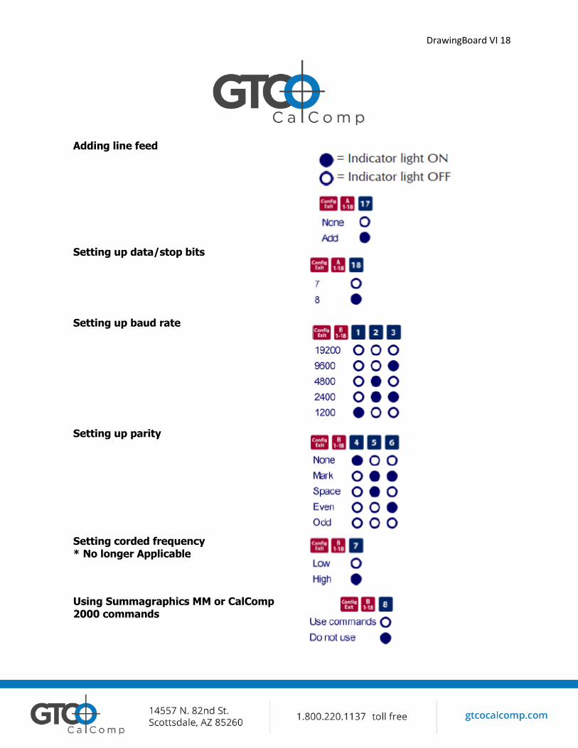
Adding line feed
Setting up data/stop bits
Setting up baud rate
Setting up parity
Setting corded frequency * No longer Applicable
Using Summagraphics MM or CalComp 2000 commands
DrawingBoard VI 19
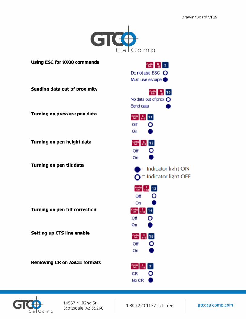
Using ESC for 9X00 commands
Sending data out of proximity
Turning on pressure pen data
Turning on pen height data
Turning on pen tilt data
Turning on pen tilt correction
Setting up CTS line enable
Removing CR on ASCII formats
DrawingBoard VI 20
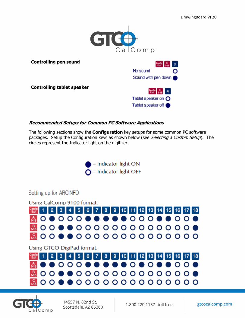
Controlling pen sound
Controlling tablet speaker
Recommended Setups for Common PC Software Applications
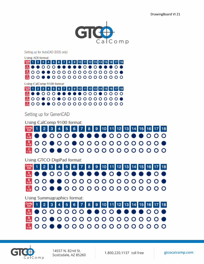
The following sections show the Configuration key setups for some common PC software packages. Setup the Configuration keys as shown below (see Selecting a Custom Setup). The circles represent the Indicator light on the digitizer.
DrawingBoard VI 21
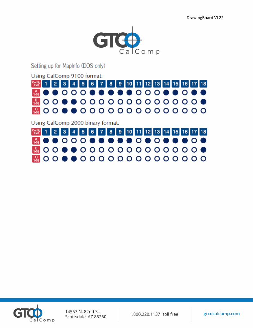
DrawingBoard VI 22
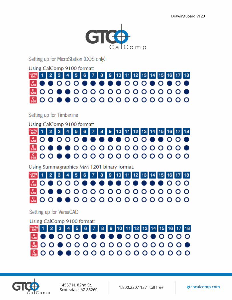
DrawingBoard VI 23
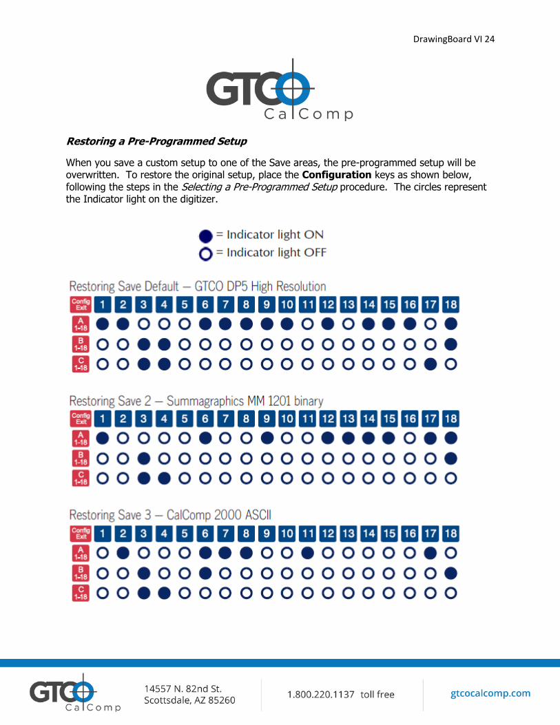
DrawingBoard VI 24
Restoring a Pre-Programmed Setup
When you save a custom setup to one of the Save areas, the pre-programmed setup will be overwritten. To restore the original setup, place the Configuration keys as shown below, following the steps in the Selecting a Pre-Programmed Setup procedure. The circles represent the Indicator light on the digitizer.
DrawingBoard VI 25
Learning the Basics
You will find that using your DrawingBoard VI tablet is as easy or easier, than using a mouse. The DrawingBoard VI transducers are more accurate than a mouse, giving you greater control over your movements.
Using the Transducer
The transducer does not need to be in contact with the tablet surface in order for the tablet to sense its presence. It can be detected up to ½” above the Active Area. When the transducer is in the zone above the surface of the digitizer, it is referred to as being in prox. The Indicator light will go from a blinking green light to a solid green light when the transducer is in prox of, or touching, the tablet’s surface. The in prox zone allows you to trace through materials placed on the digitizer’s surface, such as drawing or a book. Before using the transducer, be sure that Sleep Mode is turned off by pressing a button, or in the case of the pen, touching the tip of the tablet’s surface.
Using the Cursor
When you use the cursor, the intersection point of the crosshairs on the lens identifies the point you are selecting. The crosshairs are etched on the bottom of the lens to increase accuracy. For maximum precision, look through the lens from a position directly over it.
Button 0, is used as the pick, or left mouse, button. All other buttons are defined by the TabletWorks software, or through your own software application.
Using the Pen
The pen tip is Button 0 and is used as the pick, or left mouse, button. The lower button is Button 1 and the upper is Button 2.
The functions these buttons provide are defined through the TabletWorks software, or through your own software application.
Click Tip Pen
The click tip pen is available in both corded and cordless versions. It is primarily used for tracing and menu picking. To use the click pen, press down until you feel the tip click.
DrawingBoard VI 26
Learning Basic Movements
The DrawingBoard VI transducers provide all the basic movements of a mouse, including clicking, double-clicking and dragging.
Clicking and Double-Clicking
Clicking is the action of making a selection. You may be selecting a key on the digitizer surface, or making a selection from your computer monitor screen. To click, place the transducer, or move the screen pointer using the transducer, to the item to be selected. Tap the pen or press Button 0 on the cursor. A double-click requires you to quickly tap the pen or press the button two times, while the tool remains in the same place. You can also double-click by pressing the pen or cursor button that has been defined as a double-click button.
Dragging
Dragging is the action of moving the transducer during a selection. To drag, click on an object, but instead of lifting the pen tip or releasing the cursor button, hold it down while moving the transducer, or corresponding object on the screen, to the desired new location.
DrawingBoard VI 27
Caring for the Tablet and Transducer
Follow these precautions at all times to avoid damaging your DrawingBoard VI:
Avoid discharging static electricity to the tablet. Do not place heavy objects on the tablet surface. Do not use sharp objects, such as compasses or knives, on the tablet surface. Do not use the tablet surface for any purpose other than drawing, tracing or digitizing. Do not drill any holes on the digitizer or controller.
Cleaning the Tablet
To clean the tablet’s surface, use a soft, non-abrasive cloth. Hardened dirt may be removed with a slightly dampened cloth. Do not clean pencil lines with a soft cleanser or pencil eraser. This may create an undesirable shiny spot on the tablet’s surface that cannot be removed.
Cleaning the Cursor
To clean the cursor body, use a mild cleanser. Do not spray the cleanser directly on the cursor – instead, dampen a soft cloth with a mixture of water and the cleanser. Clean the cursor reticles with alcohol.
DrawingBoard VI 28
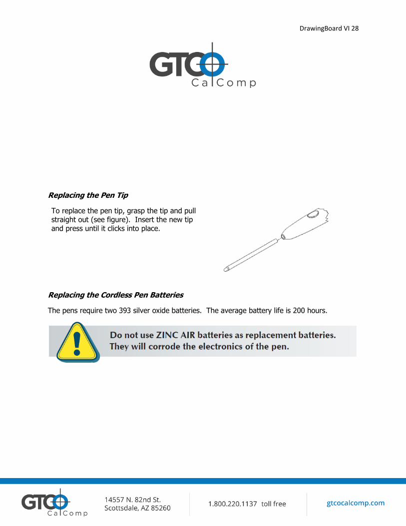
Replacing the Pen Tip
To replace the pen tip, grasp the tip and pull straight out (see figure). Insert the new tip and press until it clicks into place.
Replacing the Cordless Pen Batteries
The pens require two 393 silver oxide batteries. The average battery life is 200 hours.
DrawingBoard VI 29
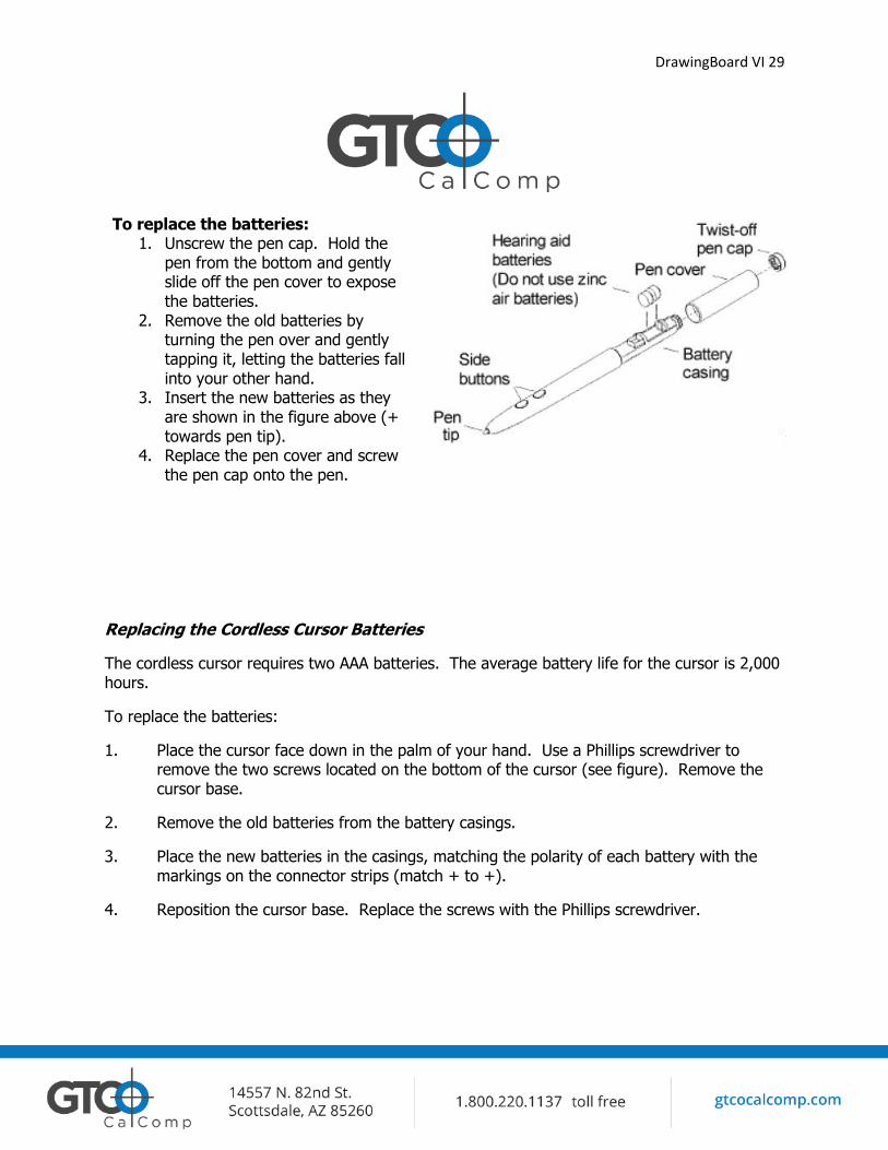
To replace the batteries: 1. Unscrew the pen cap. Hold the
pen from the bottom and gently slide off the pen cover to expose the batteries.
2. Remove the old batteries by turning the pen over and gently tapping it, letting the batteries fall into your other hand.
3. Insert the new batteries as they are shown in the figure above (+ towards pen tip).
4. Replace the pen cover and screw the pen cap onto the pen.
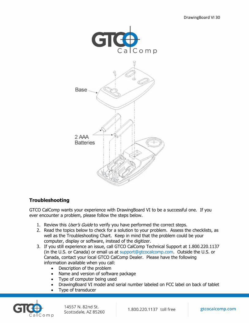
Replacing the Cordless Cursor Batteries
The cordless cursor requires two AAA batteries. The average battery life for the cursor is 2,000 hours.
To replace the batteries:
1. Place the cursor face down in the palm of your hand. Use a Phillips screwdriver to remove the two screws located on the bottom of the cursor (see figure). Remove the cursor base.
2. Remove the old batteries from the battery casings.
3. Place the new batteries in the casings, matching the polarity of each battery with the markings on the connector strips (match + to +).
4. Reposition the cursor base. Replace the screws with the Phillips screwdriver.
DrawingBoard VI 30
Troubleshooting
GTCO CalComp wants your experience with DrawingBoard VI to be a successful one. If you ever encounter a problem, please follow the steps below.
1. Review this User’s Guide to verify you have performed the correct steps. 2. Read the topics below to check for a solution to your problem. Assess the checklists, as
well as the Troubleshooting Chart. Keep in mind that the problem could be your computer, display or software, instead of the digitizer.
3. If you still experience an issue, call GTCO CalComp Technical Support at 1.800.220.1137 (in the U.S. or Canada) or email us at [email protected]. Outside the U.S. or Canada, contact your local GTCO CalComp Dealer. Please have the following information available when you call:
Description of the problem Name and version of software package Type of computer being used DrawingBoard VI model and serial number labeled on FCC label on back of tablet Type of transducer
DrawingBoard VI 31
Tablet Checklist
Is the tablet power supply plugged into the digitizer and into a live outlet? Is the tablet power switch on? Does the Indicator light glow steadily when the transducer is in prox inside the Active
Area? Does the Indicator LED Blink when the transducer is outside the Active Area? The Indicator light will be off if the transducer has gone into Sleep Mode. Press any
button on the transducer to activate it. If the transducer is in the Active Area and the Indicator light remains off, change the transducer’s battery.
Are all cable connections seated properly? Is the communications cable (either USB or serial) connected to both the digitizer and
the computer? Check that the cable is connected to the serial port specified in your software package.
Is the transducer cable connected to the digitizer? Is the tablet setup according to the software recommendations? Are any of the connector cables or receptacles damaged? Check for bent pins, cut
insulation and loose wires.
Computer Checklist
Is the computer plugged into a live outlet? Did you turn on the computer? Does the computer work with any of your software? Try one of your other programs. Is your software package installed correctly? If your communications connection is USB, does the USB port work? If serial, does the
serial port work? The only way to test the port without special equipment is to reinstall something that has worked in the past and see if it still works.
Have there been any recent electrical storms in your area that may have damaged your equipment?
DrawingBoard VI 32
Software Checklist
Does the tablet work with some software?
If your tablet currently works with some software packages, you know that the tablet, USB or serial port and computer work.
Even if the software package you are trying to install and the software that is working both support the same tablets, it does not always mean that you can use the same tablet settings. The output format may be the same, but the communications protocol, resolution, operating mode and data rate may be different. Check your software’s requirements.
Call the software manufacturer. Perhaps the software package has a problem with another component of your system.
Did the software work in the past?
If the software package worked with the tablet in the past, then the problem lies with the new setup.
Check all the connectors. Is the tablet still plugged into the same port? If yes, reset the tablet by unplugging and re-plugging the USB connector, or, if you are using serial, unplug and re-plug the power supply. Restart the software.
Did you reset or power down the computer? If you are using a serial connection, during reset and power-on, the computer can send
meaningless characters out the serial port and this can disable the tablet. Reset the tablet again.
Have you installed any new software or hardware? Remove it from your system and see if the problem goes away.
Did you move any cables? Have you updated the software or its drivers? Are you loading another mouse driver, or do you have multiple mouse drivers? Did you reinstall the software, perhaps after a problem with your hard drive? Double
check your installation procedure and the driver you selected.
Reinstall the software from its master. The program files may have been corrupted.
DrawingBoard VI 33
Troubleshooting Chart
The following tablet lists common DrawingBoard VI problems, their causes and their solutions.
Problem Cause Solution *Frozen screen pointer * * * * * Screen pointer appears to shake or jitter
Transducer is in Sleep Mode. Menu Strip is in Configuration Mode. Tablet plugged into the wrong serial port on the computer. Tablet not powered correctly. Batteries low in transducer. Software application setup incorrectly. Another device is connected to a COM port that shares the same IRQ as the tablet COM port (i.e., your tablet is connected to COM1 IRQ4 and your modem is connected to COM3 IRQ4). Tablet is set too close to the screen monitor.
Press any button on the transducer. If the configuration light is on, click on the Config/Exit key on the Menu Strip. Is the serial port being used correctly identified in your software application? Check that the power cable is installed correctly. Replace the batteries in the transducer. Check that the tablet is identified in your software application. Move one of the devices to another COM port. Contact your system manufacturer for assistance in relocating the device. Move the tablet farther away from the screen.
DrawingBoard VI 34
Intermittent issue using Cordless pointer Unable to use the entire tablet surface
Lines jump, can’t pic area On tablet Incorrect format selected. Software application setup incorrectly.
Check lighting/bad Ballast. Turn off lights. Try digitizing Again. Check your selections in the Menu Strip. Check that the tablet is identified in your software application.
Returning your Tablet for Repair
If you believe you have a defective tablet contact Technical Support at 1.800.220.1137 or email us at [email protected].
Technical Support will assist you in determining if your tablet is defective and will help you obtain a Return Merchandise Authorization (RMA) number. Important: Please do not return your product without first discussing the issue with, and receiving an RMA from GTCO CalComp Technical Support.
Repackaging for Shipment
Whenever you ship electronic equipment, try to ship it in its original packing materials. Place a copy of the RMA in with your Item(s) you are returning and write the RMA number on the package.
Parts and Accessories
Please contact GTCO CalComp at 1.800.220.1137 or email [email protected]
DrawingBoard VI 35
Glossary
Accuracy The similarity of a distance measured by the tablet with the actual distance. When we specify that the accuracy of a tablet is ± .010 inches, we mean that every point in the Active Area is within .010 inches of where it should be. ASCII Abbreviation for American Standard Code for Information Interchange. Baud Rate Rate of speed that data flows between a host computer and the digitizer. It is the number of bits transmitted per second. The lower the baud rate, the slower the speed. Bit Basic unit of information in the binary system – either 0 or 1. Button Switch on the cursor or pen used to input data. Byte Group of eight bits that acts as a single unit of information. Coordinate Pair Pair of numbers representing a unique point on the digitizer surface, usually the distance across and up from the tablet origin. CR The ASCII Carriage Return character usually added to the end of the X,Y coordinate pairs sent by the tablet (ASCII formats). Cursor
1.) Transducer used to select specific points on the tablet surface. 2.) Symbol displayed on the screen marking where the next action will take effect, or
where the next character typed from the keyboard will appear. Data Bits Each transmission contains 7 or 8 data bits. Data Rate Number of coordinate pairs (X,Y) the tablet sends to the computer per second.
DrawingBoard VI 36
Default A value, action or setting that a computer system assumes, unless the user gives an explicit instruction to the contrary. Drawing Area Area on the tablet surface intended for digitizing. Referred to as the Active Area. Format The form in which data is sent from the tablet. DrawingBoard VI tablet can output 32 different formats. Frequency Number of waves that pass a fixed point in one second. Height See Proximity. Increment Modes This mode is used with other operating modes. Data points are sent only if the transducer has moved the required increment distance in either the X or Y direction and has satisfied the requirements of the operating mode. These increment distances are set separately for each axis. Jitter Repeatability error of short duration caused by electrical noise. Key Portion of the tablet surface available to the user for tablet setup. Line Feed Optional character added to the end of an output format that causes the printer to move to the next line, or causes a line to be added on the display screen. Line Mode The tablet sends coordinate data points continuously, while the pen tip or a cursor button is depressed, and one additional point when the pen tip or cursor button is released. LPI Abbreviation for lines per inch. English unit of measurement for resolution measuring the number of separate, distinguishable locations that may be found within the distance of one inch.
DrawingBoard VI 37
LPmm Abbreviation for lines per millimeter. Metric unit of measurement for resolution measuring the number of separate, distinguishable locations that may be found within the distance of one millimeter. Mouse Mode Operating mode that emulates Microsoft and Mouse Systems mouse drivers. Data constantly transmits when the cursor or pen is on the drawing area of the tablet. Operating Mode The conditions that must be met before the tablet sends information to the computer. Output Format System of characters used by the DrawingBoard VI tablet for outputting data. Parity Type of error detection where a bit is inserted into every character the digitizer transmits. The status of the parity bit confirms that the data was not altered during transmission. Point Mode The digitizer transmits one coordinate data point when a cursor button or the pen tip is depressed. Prompt Mode The digitizer transmits one coordinate pair each time the computer sends a prompt character to the unit. Prompting can operate with any mode except Mouse mode. Proximity Greatest distance above the Active Area that the transducer can be raised and still be sensed by the tablet. RAM Abbreviation for Random Access Memory, a specific type of memory used by the computer. Resolution Distance increment that the tablet outputs in lines/inch or lines/mm. ROM Abbreviation for Read Only Memory, a specific type of memory used by the computer. Run Mode The digitizer transmits coordinate data points continuously, regardless of the status of the cursor buttons or the pen tip. This mode is also called Stream by some manufacturers.
DrawingBoard VI 38
Serial Transmission Data transmission protocol where each bit of the data character is sent one at a time over a single circuit. This system saves on transmission circuitry, but is usually slower than parallel transmission. Stop Bits One or two stop bits are transmitted with each data byte. They mark a completed transmission. Track Mode The digitizer transmits coordinate data points continuously, but only while the cursor button or pen tip is depressed. This mode is also called Switch Stream by some manufacturers. Transducer Tool used to digitize; it may be either a cursor or pen. X Direction Horizontal direction across the face of the tablet. Y Direction Vertical distance up and down the face of the tablet.
Regulatory Statements and Warranty
Radio and Television Interference
The user is cautioned that any changes or modifications not expressly approved by the party responsible for compliance could void the user’s authority to operate the equipment.
This equipment has been tested and found to comply with the limits of a Class B digital device, pursuant to Part 15 of the FCC rules. These limits are designed to provide reasonable protection against harmful interference in a residential installation. This equipment generates, uses and can radiate radio frequency energy and, if not installed and used in accordance with the instructions, may cause harmful interference to radio communications. However, there is no guarantee the interference will not occur in a particular installation. If this equipment does cause harmful interference to radio or television reception, which can be determined by turning the equipment off and on, the user is encouraged to try to correct the interference by one or more of the following measures:
Reorient or relocate the receiving antenna. Increase the separation between the equipment and the receiver.
DrawingBoard VI 39
Connect the equipment into an outlet on a circuit different from that to which the receiver is connected.
Reorient or coil cables. Consult the dealer or an experienced Radio/TV technician for help.
NOTE: Any cables the user adds to the device must be shielded to be in compliance with the FCC standards. Any unauthorized modification to this device could result in the revocation of the end user’s authority to operate this device.
Canada
This digital apparatus does not exceed the Class B limits for radio noise emissions from digital apparatus as set out in the radio interference regulations of the Canadian Department of Communications.
Le present appareil numérique n’emet pas bruits radioelectriques depassant les limites applicables aux appareils numériques de Classe B prescrites dans le réglement sur le brouillage radioelectrique edicte par le Ministere des Communications du Canada.
European Union Emission Directive
This product is in conformity with the protection requirements of EU Council Directive 89/366/ECC on the approximation of the laws of the Member States relating to electromagnetic compatibility.
This product has been tested and found to comply with the limits for Class B Information Technology Equipment according to CISPR 22/European Standard EN55022. The limits for Class B equipment were derived for typical industrial environments to provide reasonable protection against interference with licensed communication devices.
European Union WEEE Directive
The manufacture of this equipment required the extraction and use of natural resources. It may contain hazardous substances that could impact health and the environment.
In order to avoid the dissemination of the hazardous substances into the environment and to diminish the pressure on our natural resources, GTCO CalComp encourages you to return this product to the appropriate take-back system facility. These facilities reuse or recycle most of the materials in this equipment in a responsible way.
The crossed-out wheeled bin symbol below invites you to use these take-back systems. If you need more information about the collection, reuse and recycling systems in your
area, please contact your local or regional waste authority.
Further information about the responsible end-of-life management of this and other GTCO CalComp products is available on our website at www.gtcocalcomp.com.
DrawingBoard VI 40
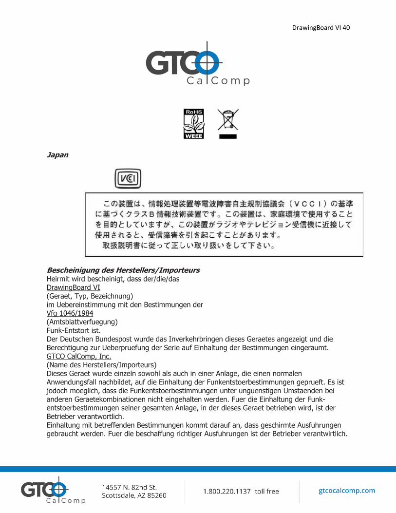
Japan
Bescheinigung des Herstellers/Importeurs Heirmit wird bescheinigt, dass der/die/das DrawingBoard VI (Geraet, Typ, Bezeichnung) im Uebereinstimmung mit den Bestimmungen der Vfg 1046/1984 (Amtsblattverfuegung) Funk-Entstort ist. Der Deutschen Bundespost wurde das Inverkehrbringen dieses Geraetes angezeigt und die Berechtigung zur Ueberpruefung der Serie auf Einhaltung der Bestimmungen eingeraumt. GTCO CalComp, Inc. (Name des Herstellers/Importeurs) Dieses Geraet wurde einzeln sowohl als auch in einer Anlage, die einen normalen Anwendungsfall nachbildet, auf die Einhaltung der Funkentstoerbestimmungen geprueft. Es ist jodoch moeglich, dass die Funkentstoerbestimmungen unter unguenstigen Umstaenden bei anderen Geraetekombinationen nicht eingehalten werden. Fuer die Einhaltung der Funk-entstoerbestimmungen seiner gesamten Anlage, in der dieses Geraet betrieben wird, ist der Betrieber verantwortlich. Einhaltung mit betreffenden Bestimmungen kommt darauf an, dass geschirmte Ausfuhrungen gebraucht werden. Fuer die beschaffung richtiger Ausfuhrungen ist der Betrieber verantwirtlich.
DrawingBoard VI 41
Limited Warranty for DrawingBoard VI GTCO CalComp warrants these products to be free from defects in material and workmanship under the
following terms.
Coverage
Parts and labor are warranted for one (1) year from the date of the first consumer purchase for the digitizer tablet, controller, transducers and tablet accessories. Power supply and cables are also
warranted for one (1) year. This warranty applies to the original consumer purchaser only.
Within the European Union, the warranty period is two (2) years, as mandated by the EU. Contact your
local dealer or distributor for additional warranty information.
Warranty information will be captured by the system serial number and confirmed by the reseller’s
purchase order.
A nominal Diagnostic Fee will be charged after 1 year of use and calculated from the date of original consumer purchase.
Conditions
Except as specified below, this warranty covers all defects in material or workmanship in the products.
The following are not covered by the warranty: 1. Any product on which the serial number has been defaced, modified or removed (if applicable).
2. Damage, deterioration or malfunction resulting from: a. Accident, misuse, abuse, neglect, fire, water, lightning or other acts of nature,
unauthorized modification for any purpose, unauthorized product modification, or failure
to follow instructions supplied with the product. b. Repair or attempted repair by anyone not authorized by GTCO CalComp.
c. Any damage in shipment of the product (claims must be presented to the carrier). d. Any other cause which does not relate to a manufacturing defect.
GTCO CalComp will pay all labor and material expenses for covered items, but will not pay for the
following:
1. Removal or installation charges. 2. Costs for initial technical adjustments (setup), including adjustment of user controls.
3. Certain shipping charges. (Payment of shipping charges is discussed in the next section of this warranty.)
4. Packaging costs. (Customers should keep their boxes.)
Warranty Service Procedures
DrawingBoard VI 42
1. To obtain service on your GTCO CalComp product, contact the Technical Support Department to receive a Return Material Authorization Number (RMA#) and shipping instructions by calling:
1.800.220.1137 2. Ship the product to GTCO CalComp with the RMA# marked clearly on the outside of the box.
Without a clearly marked RMA# on the shipping box, GTCO CalComp reserves the right to refuse the shipment.
3. Although you must pay any shipping charges to ship the product to GTCO CalComp for warranty
service, GTCO CalComp will pay the return shipping charges for ground shipment. Other shipping options are available at an additional fee.
4. If GTCO CalComp determines that the unit is not defective within the terms of the warranty, the consumer shall pay the cost of all freight charges, as well as any repair charges.
Technical Support Web-based Technical Support is available free of charge at: www.gtcocalcomp.com
Telephone Technical Support is available free of charge to the original consumer. Please contact our
Technical Support Department at: 1.800.220.1137
Disclaimer of Unstated Warranties
The warranty printed above is the only warranty applicable to this purchase. ALL OTHER WARRANTIES, EXPRESS OR IMPLIED, INCLUDING, BUT NOT LIMITED TO, THE IMPLIED WARRANTIES OF
MERCHANTABILITY AND FITNESS FOR A PARTICULAR PURPOSE ARE DISCLAIMED. Assuming the
warranty above stated is otherwise applicable, it is expressly understood and agreed that GTCO CalComp sole liability whether in contract, tort, under any warranty, in negligence or other shall be for the repair
or replacement of the defective parts and under no circumstances shall GTCO CalComp be liable for special, indirect or consequential damages. The price stated and paid for the equipment is a
consideration in limiting GTCO CalComp liability.
Notice
Some states and provinces do not allow the exclusion or limitation of incidental or consequential damages, so the above exclusion may not apply to you. This warranty gives you specific legal rights, and
you may have other rights, which vary from state to state, or province to province.

DrawingBoard VI 43
Corporate Headquarters 14557 N. 82nd Street
Scottsdale, Arizona 85260 Sales and Support:
1.800.220.1137
DRAWINGBOARD VI™
Copyright© 2014 GTCO CalComp by Turning Technologies, Inc. DrawingBoard VI is a trademark of GTCO CalComp by Turning Technologies, Inc.
All other products and company names are the trademarks or registered trademarks of their respective owners.
The information contained in this document is subject to change without notice. GTCO CalComp by Turning
Technologies assumes no responsibility for technical, or editorial errors, or omissions that may appear in this document, or for the use of this material. Nor does GTCO CalComp by Turning Technologies make any
commitment to update the information contained in this document. This document contains proprietary information which is protected by copyright. All rights reserved. No part of this document can be photocopied or
reproduced in any form without the prior, written consent of GTCO CalComp by Turning Technologies, Inc.
36-01239/37-01099-01 Rev. D